Embed Size (px)
Citation preview

Guard I/O DeviceNet Safety ModulesCatalog Numbers 1732DS-IB8, 1732DS-IB8XOBV4, 1791DS-IB12, 1791DS-IB8XOB8, 1791DS-IB4XOW4, 1791DS-IB8XOBV4, 1791DS-IB16
User Manual

Important User Information Solid state equipment has operational characteristics differing from those of electromechanical equipment. Safety Guidelines for the Application, Installation and Maintenance of Solid State Controls (publication SGI-1.1 available from your local Rockwell Automation sales office or online at http://literature.rockwellautomation.com) describes some important differences between solid state equipment and hard-wired electromechanical devices. Because of this difference, and also because of the wide variety of uses for solid state equipment, all persons responsible for applying this equipment must satisfy themselves that each intended application of this equipment is acceptable.
In no event will Rockwell Automation, Inc. be responsible or liable for indirect or consequential damages resulting from the use or application of this equipment.
The examples and diagrams in this manual are included solely for illustrative purposes. Because of the many variables and requirements associated with any particular installation, Rockwell Automation, Inc. cannot assume responsibility or liability for actual use based on the examples and diagrams.
No patent liability is assumed by Rockwell Automation, Inc. with respect to use of information, circuits, equipment, or software described in this manual.
Reproduction of the contents of this manual, in whole or in part, without written permission of Rockwell Automation, Inc., is prohibited.
Throughout this manual, when necessary, we use notes to make you aware of safety considerations.
Allen-Bradley, ArmorBlock, CompactBlock, CompactBlock Guard I/O, GuardLogix, GuardPLC, Logix 5000, Rockwell Automation, RSLogix 5000, RSLogix Guard Plus!, RSNetWorx, SmartGuard, and TechConnect are trademarks of Rockwell Automation, Inc. Trademarks not belonging to Rockwell Automation are property of their respective companies.
WARNINGIdentifies information about practices or circumstances that can cause an explosion in a hazardous environment, which may lead to personal injury or death, property damage, or economic loss.
IMPORTANT Identifies information that is critical for successful application and understanding of the product.
ATTENTION Identifies information about practices or circumstances that can lead to personal injury or death, property damage, or economic loss. Attentions help you identify a hazard, avoid a hazard, and recognize the consequence
SHOCK HAZARD Labels may be on or inside the equipment, for example, a drive or motor, to alert people that dangerous voltage may be present.
BURN HAZARD Labels may be on or inside the equipment, for example, a drive or motor, to alert people that surfaces may be at dangerous temperatures.

Summary of Changes
This publication contains new and revised information not in the last release.
Revised Information See the table for a summary of the major revisions to this manual.
New Information See the table for a summary of the major additions to this manual.
Change Bars Change bars (as shown with this paragraph) show the areas in this manual that are different from previous editions and indicate the addition of new or revised information.
For Revised See
Definition for electronic data sheet Page 6
Attention statement Page 8
Vertical mount graphic Page 37
RSLogix 5000 software usage instructions Chapter 4
PFH and PFD values Page 113
For New See
1791DS-IB16 figure Page 18
RSNetworx for DeviceNet software usage instructions Chapter 5
1791DS-IB16 PFH and PFD values Page 114
1791DS-IB16 configuration data Appendix D
SmartGuard 600 code example Appendix F
3 Publication 1791DS-UM001E-EN-P - January 2007

4 Summary of Changes
Notes:
Publication 1791DS-UM001E-EN-P - January 2007
Table of Contents
Preface What This Preface Contains . . . . . . . . . . . . . . . . . . . . . . . . . . 5Who Should Use This Manual . . . . . . . . . . . . . . . . . . . . . . . . 5Common Techniques Used in This Manual. . . . . . . . . . . . . . . 5Additional Resources. . . . . . . . . . . . . . . . . . . . . . . . . . . . . . . 5How To Use This Manual . . . . . . . . . . . . . . . . . . . . . . . . . . . 6About the Specifications and Dimensions in This Manual . . . . 6Terminology . . . . . . . . . . . . . . . . . . . . . . . . . . . . . . . . . . . . . 6
Chapter 1About the Modules What This Chapter Contains . . . . . . . . . . . . . . . . . . . . . . . . . 7
Before You Begin . . . . . . . . . . . . . . . . . . . . . . . . . . . . . . . . . 7Understand Suitability for Use . . . . . . . . . . . . . . . . . . . . . . . . 8Follow Precautions for Use . . . . . . . . . . . . . . . . . . . . . . . . . . 8Follow Precautions for Mounting, Wiring, and Cleaning. . . . 11I/O Module Overview . . . . . . . . . . . . . . . . . . . . . . . . . . . . . 12About Catalog Numbers . . . . . . . . . . . . . . . . . . . . . . . . . . . 13About CIP Safety in DeviceNet Safety Architectures . . . . . . . 14Identify Major Parts of the Modules . . . . . . . . . . . . . . . . . . . 15
Chapter 2Understand the Operation of Safety Functions
What This Chapter Contains . . . . . . . . . . . . . . . . . . . . . . . . 19Safety I/O Modules . . . . . . . . . . . . . . . . . . . . . . . . . . . . . . . 19Safety Inputs. . . . . . . . . . . . . . . . . . . . . . . . . . . . . . . . . . . . 20Safety Outputs . . . . . . . . . . . . . . . . . . . . . . . . . . . . . . . . . . 27I/O Status Data . . . . . . . . . . . . . . . . . . . . . . . . . . . . . . . . . . 29Controlling Devices. . . . . . . . . . . . . . . . . . . . . . . . . . . . . . . 30Safety Precautions . . . . . . . . . . . . . . . . . . . . . . . . . . . . . . . . 31Legislation and Standards . . . . . . . . . . . . . . . . . . . . . . . . . . 31EC Directives . . . . . . . . . . . . . . . . . . . . . . . . . . . . . . . . . . . 33
Chapter 3Install and Connect Your Modules What This Chapter Contains . . . . . . . . . . . . . . . . . . . . . . . . 35
Install the Module . . . . . . . . . . . . . . . . . . . . . . . . . . . . . . . . 36Connect I/O Power and I/O Cables . . . . . . . . . . . . . . . . . . . 37Connect Communication Connectors . . . . . . . . . . . . . . . . . . 39Set the Node Address . . . . . . . . . . . . . . . . . . . . . . . . . . . . . 40Configure the Module . . . . . . . . . . . . . . . . . . . . . . . . . . . . . 40
1 Publication 1791DS-UM001E-EN-P - January 2007
2 Table of Contents
Chapter 4Configure Modules in RSLogix 5000 Software
What This Chapter Contains . . . . . . . . . . . . . . . . . . . . . . . . 41Use the Help Button . . . . . . . . . . . . . . . . . . . . . . . . . . . . . . 41Add Safety Modules to the I/O Configuration Tree . . . . . . . . 41Use the Module Properties and General Dialogs. . . . . . . . . . 44Work with the Safety Dialog . . . . . . . . . . . . . . . . . . . . . . . . 51Work with the Input Configuration Dialog . . . . . . . . . . . . . . 54Work with Test Output Configuration Dialog . . . . . . . . . . . . 57Work with the Output Configuration Dialog. . . . . . . . . . . . . 58Save Module Configuration . . . . . . . . . . . . . . . . . . . . . . . . . 60Status Data Supported by Each Module . . . . . . . . . . . . . . . . 60
Chapter 5Configure Modules in RSNetWorx Software
What This Chapter Contains . . . . . . . . . . . . . . . . . . . . . . . . 61Configure a SmartGuard Controller . . . . . . . . . . . . . . . . . . . 61
Chapter 6Wiring Examples What This Chapter Contains . . . . . . . . . . . . . . . . . . . . . . . . 85
Examples of Wiring . . . . . . . . . . . . . . . . . . . . . . . . . . . . . . 87
Chapter 7Interpret the LED Indicators What This Chapter Contains . . . . . . . . . . . . . . . . . . . . . . . . 97
1791DS-IB12, 1791DS-IB8XOB8, 1791DS-IB4XOW4 Module LED Indicators . . . . . . . . . . . . . . . . . . . . . . . . . . . . . . . . . . . . . . 971791DS-IB8XOBV4, 1791DS-IB16, 1732DS-IB8XOBV4, 1732DS-IB8 Module LED Indicators . . . . . . . . . . . . . . . . . . 100
Chapter 8Maintain Your Modules What This Chapter Contains . . . . . . . . . . . . . . . . . . . . . . . 103
Troubleshoot . . . . . . . . . . . . . . . . . . . . . . . . . . . . . . . . . . 103Maintenance . . . . . . . . . . . . . . . . . . . . . . . . . . . . . . . . . . . 106
Appendix ADeviceNet Explicit Messages What This Appendix Contains . . . . . . . . . . . . . . . . . . . . . . 109
Basic Format of Explicit Messages . . . . . . . . . . . . . . . . . . . 109Explicit Messages . . . . . . . . . . . . . . . . . . . . . . . . . . . . . . . 111
Appendix BProbability of Failure on Demand (PFD), Probability of Failure per Hour (PFH), and Mean Time Between (MTBF) Data
What This Appendix Contains . . . . . . . . . . . . . . . . . . . . . . 113Calculated Values . . . . . . . . . . . . . . . . . . . . . . . . . . . . . . . 113
Publication 1791DS-UM001E-EN-P - January 2007
Table of Contents 3
Appendix CList of Functions What This Appendix Contains . . . . . . . . . . . . . . . . . . . . . . 115
List of Functions . . . . . . . . . . . . . . . . . . . . . . . . . . . . . . . . 115
Appendix DConfiguration Reference Information
What This Appendix Contains . . . . . . . . . . . . . . . . . . . . . . 119Understand Parameter Groups . . . . . . . . . . . . . . . . . . . . . . 119Allocate Remote I/O . . . . . . . . . . . . . . . . . . . . . . . . . . . . . 121I/O Data Supported by Each Module . . . . . . . . . . . . . . . . . 123I/O Assembly and Reference Data . . . . . . . . . . . . . . . . . . . 131
Appendix EGet Point Status from Safety I/O Modules by Using Explicit Messaging
What This Appendix Contains . . . . . . . . . . . . . . . . . . . . . . 141Work with 1791DS-IB8XOB8 Modules . . . . . . . . . . . . . . . . 141Work with 1791DS-IB4XOW4 Modules . . . . . . . . . . . . . . . 145Work with 1791DS-IB12 Modules. . . . . . . . . . . . . . . . . . . . 148
Appendix FCreate SmartGuard 600 Code: An Example
What This Appendix Contains . . . . . . . . . . . . . . . . . . . . . . 151Putting the SmartGuard 600 into Run Mode . . . . . . . . . . . . 175
Appendix GSpecifications Guard I/O DeviceNet Safety Module 1791DS-IB8XOBV4. . . 177
Guard I/O DeviceNet Safety Module 1791DS-IB12, 1791DS-IB8XOB8, 1791DS-IB4XOW4. . . . . . . . . . . . . . . . . 181
Index
Publication 1791DS-UM001E-EN-P - January 2007
4 Table of Contents
Notes
Publication 1791DS-UM001E-EN-P - January 2007
Preface
What This Preface Contains This preface describes how to use this manual.
Who Should Use This Manual
This manual is intended for users of ArmorBlock Guard I/O and CompactBlock Guard I/O DeviceNet safety I/O modules.
Common Techniques Used in This Manual
The following conventions are used throughout this manual.
Numbered lists provide sequential steps.
Bulleted lists provide information, not procedural steps.
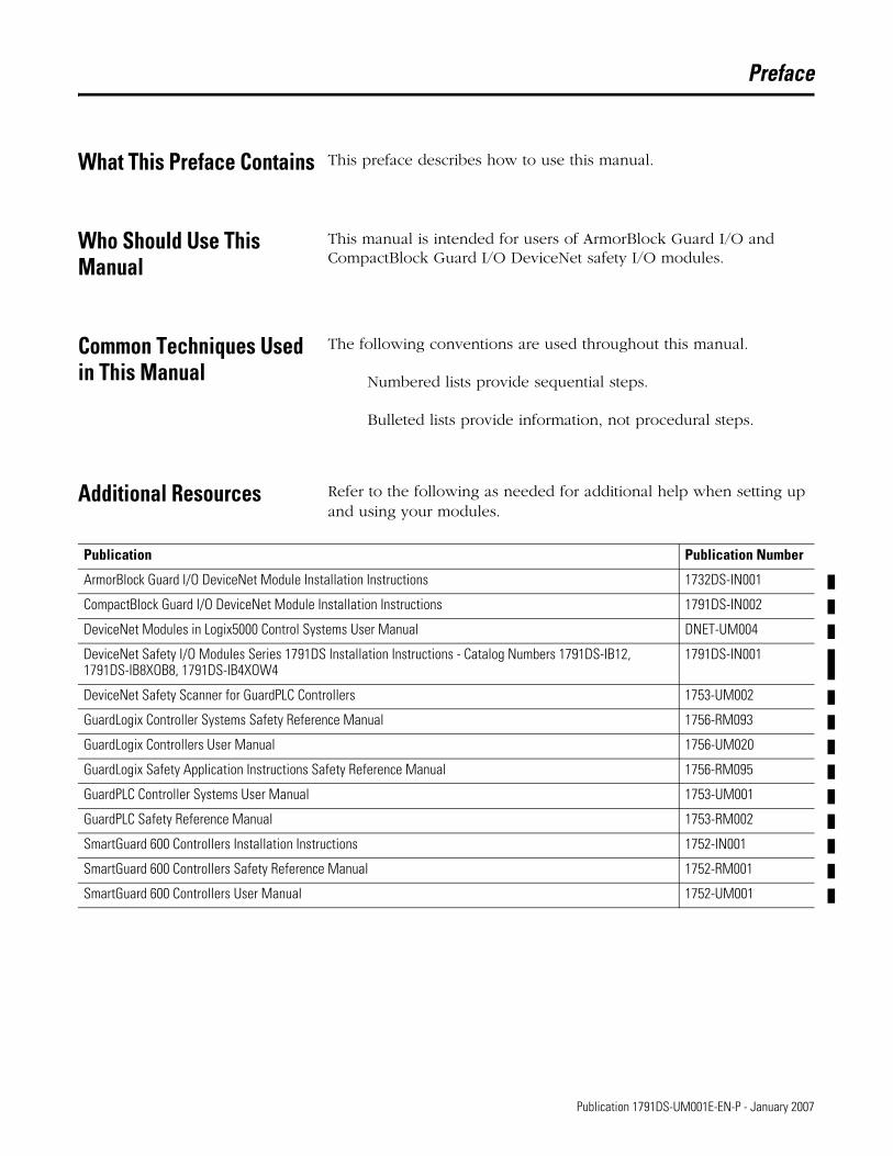
Additional Resources Refer to the following as needed for additional help when setting up and using your modules.
Publication Publication Number
ArmorBlock Guard I/O DeviceNet Module Installation Instructions 1732DS-IN001
CompactBlock Guard I/O DeviceNet Module Installation Instructions 1791DS-IN002
DeviceNet Modules in Logix5000 Control Systems User Manual DNET-UM004
DeviceNet Safety I/O Modules Series 1791DS Installation Instructions - Catalog Numbers 1791DS-IB12, 1791DS-IB8XOB8, 1791DS-IB4XOW4
1791DS-IN001
DeviceNet Safety Scanner for GuardPLC Controllers 1753-UM002
GuardLogix Controller Systems Safety Reference Manual 1756-RM093
GuardLogix Controllers User Manual 1756-UM020
GuardLogix Safety Application Instructions Safety Reference Manual 1756-RM095
GuardPLC Controller Systems User Manual 1753-UM001
GuardPLC Safety Reference Manual 1753-RM002
SmartGuard 600 Controllers Installation Instructions 1752-IN001
SmartGuard 600 Controllers Safety Reference Manual 1752-RM001
SmartGuard 600 Controllers User Manual 1752-UM001
5 Publication 1791DS-UM001E-EN-P - January 2007
6 Preface
How To Use This Manual Read and understand this manual before using the described products. Consult your Rockwell Automation representative if you have any questions or comments. This manual describes how to use modules.
About the Specifications and Dimensions in This Manual
Product specifications and accessories can change at any time based on improvements and other reasons. Consult with your Rockwell Automation representative to confirm actual specifications of purchased product. Dimensions and weights are nominal and are not for use for manufacturing purposes, even when tolerances are shown.
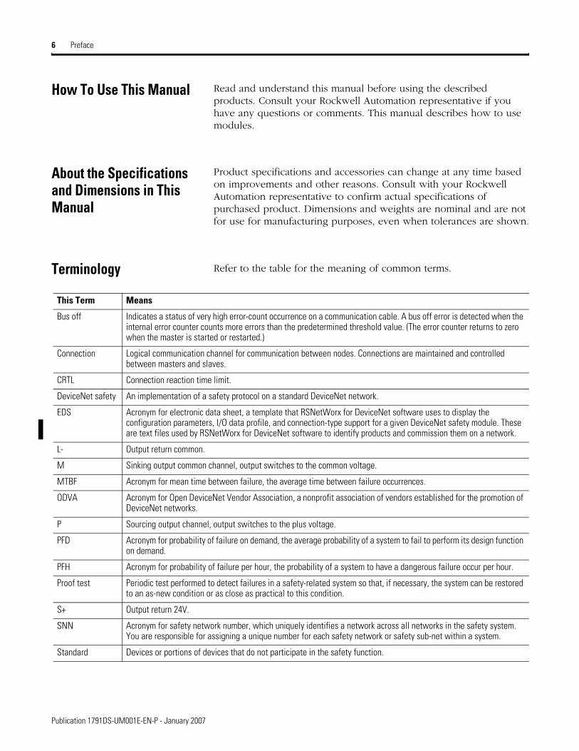
Terminology Refer to the table for the meaning of common terms.
This Term Means
Bus off Indicates a status of very high error-count occurrence on a communication cable. A bus off error is detected when the internal error counter counts more errors than the predetermined threshold value. (The error counter returns to zero when the master is started or restarted.)
Connection Logical communication channel for communication between nodes. Connections are maintained and controlled between masters and slaves.
CRTL Connection reaction time limit.
DeviceNet safety An implementation of a safety protocol on a standard DeviceNet network.
EDS Acronym for electronic data sheet, a template that RSNetWorx for DeviceNet software uses to display the configuration parameters, I/O data profile, and connection-type support for a given DeviceNet safety module. These are text files used by RSNetWorx for DeviceNet software to identify products and commission them on a network.
L- Output return common.
M Sinking output common channel, output switches to the common voltage.
MTBF Acronym for mean time between failure, the average time between failure occurrences.
ODVA Acronym for Open DeviceNet Vendor Association, a nonprofit association of vendors established for the promotion of DeviceNet networks.
P Sourcing output channel, output switches to the plus voltage.
PFD Acronym for probability of failure on demand, the average probability of a system to fail to perform its design function on demand.
PFH Acronym for probability of failure per hour, the probability of a system to have a dangerous failure occur per hour.
Proof test Periodic test performed to detect failures in a safety-related system so that, if necessary, the system can be restored to an as-new condition or as close as practical to this condition.
S+ Output return 24V.
SNN Acronym for safety network number, which uniquely identifies a network across all networks in the safety system. You are responsible for assigning a unique number for each safety network or safety sub-net within a system.
Standard Devices or portions of devices that do not participate in the safety function.
Publication 1791DS-UM001E-EN-P - January 2007
Chapter 1
About the Modules
What This Chapter Contains This chapter includes important overview information and precautions for use of the safety I/O modules that implement the DeviceNet safety protocol. Also included is an overview on how these I/O modules are used within a safety system.
Before You Begin Always observe the following when using a module, noting that in this manual we use safety administrator to mean a person qualified, authorized, and responsible to secure safety in the design, installation, operation, maintenance, and disposal of the machine.
Make sure that a safety administrator who thoroughly understands the machine to be installed handles the module.
Thoroughly read and understand this manual before installing and operating the module.
Keep this manual in a safe place where the operator can refer to it when necessary.
Use the module properly according to the installation environment, performance, and functions of the machine.
Verify that a safety administrator conducts a risk assessment on the machine and determines module suitability before installation.
Verify that the external power supply that provides power to the I/O modules is safety extra-low voltage (SELV) rated.
Verify that the DeviceNet block safety I/O firmware version is correct prior to commissioning the safety system, noting that firmware information related to safety controllers is available at http://www.rockwellautomation.com/products/certification/ safety/index.html.
7 Publication 1791DS-UM001E-EN-P - January 2007

8 About the Modules
Understand Suitability for Use
Rockwell Automation is not responsible for conformity with any standards, codes, or regulations that apply to the combination of the products in your application or use of the product.
Take all necessary steps to determine the suitability of the product for the systems, machine, and equipment with which it is used.
Know and observe all prohibitions of use applicable to this product.
Never use the products for an application involving serious risk to life or property without making sure that the system as a whole was designed to address the risks and that the Rockwell Automation product is properly rated and installed for the intended use within the overall equipment or system.
Follow Precautions for Use
ATTENTION Safety state of the module and its data is defined as the off state.
Use the module in applications where the safety status for the module is off (0).
Serious injury may occur due to breakdown of safety outputs. Do not connect loads beyond the rated value to the safety outputs.
Serious injury may occur due to loss of required safety functions. Wire the module properly so that supply voltages or voltages for loads do not touch the safety outputs accidentally or inadvertently.
ATTENTION Use dc supply satisfying the following requirements to prevent electric shock:
A dc power supply with double or reinforced insulation, for example, according to IED/EN 60950 or EN 50178 or a transformer according to IEC/EN 61558
A dc supply satisfies requirement for class 2 circuits or limited voltage/current circuit stated in UL 508
Publication 1791DS-UM001E-EN-P - January 2007

About the Modules 9
ATTENTION Follow these precautions for safe use.
Wire conductors correctly and verify operation of the module before commissioning systems in which the module is incorporated. Incorrect wiring may lead to loss of safety function.
Do not apply dc voltages exceeding the rated voltages to the module.
Apply properly specified voltages to the module inputs. Applying inappropriate voltages causes the module to fail to perform its specified function, which leads to loss of safety functions or damage to the module.
Never use test outputs as safety outputs in any way. Test outputs are not safety outputs.
Note that after installation of the module, qualified personnel must confirm the installation and conduct trial operation and maintenance.
Note that a safety administrator familiar with the machine in which the module is to be installed must conduct and verify the installation.
Do not disassemble, repair, or modify the module. This may result in loss of safety functions.
Use only appropriate components or devices complying with relevant safety standards corresponding to the required safety category and safety integrity level.
Conformity to requirements of the safety category and safety integrity level must be determined for the entire system.
We recommend you consult a certification body regarding assessment of conformity to the required safety integrity level.
Note that you must confirm compliance with the applicable standards for the entire system.
Disconnect the module from the power supply before wiring. Devices connected to the module may operate unexpectedly if wiring is performed while power is supplied.
Publication 1791DS-UM001E-EN-P - January 2007

10 About the Modules
For 1791DS-IB4XOW4 modules, follow these instructions on isolating transformer use. Refer to the isolating transformer figure.
Use an isolating transformer to isolate between over-voltage category III and II, such as TR1, to conform to IEC 60742.
Be sure the insulation between first input and secondary output satisfies at least basic insulation of over-voltage category III.
Be sure one side of a secondary output of the isolating transformer is grounded to prevent electric shock to personnel due to a short to ground or short to the frame of the isolating transformer.
Insert fuses, in case of a short to the frame, to protect the isolating transformer and prevent electric shock to personnel, per transformer specifications, at points such as F1, F2, and F3.
Use of Isolating Transformer
1791DS-IB4XOW4
44151
L1 L2 L3
400V ac/ 230V ac
MA
MB
Load
III Over-voltage Category II
F1 F3
F2
TR1
F4 F5
MA MB
F1…F8 - FusesMA, MB - Electromagnetic SwitchesTR1 - Insulated Transformer
F6 F7 F8
Publication 1791DS-UM001E-EN-P - January 2007

About the Modules 11
Follow Precautions for Mounting, Wiring, and Cleaning
Observe these precautions to prevent operation failure, malfunctions, or undesirable effects on product performance.
When mounting modules, observe these precautions.
Use DIN rail that is 35 mm (1.38 in.) wide to mount the module into the control panel.
Mount modules to DIN rail so that the module does not fall off the DIN rail, for example, due to vibration.
Leave at least 50 mm (1.96 in.) above and below the module to allow adequate ventilation and room for wiring for 1791DS-IB8, 1791DS-IB8XOB8, and 1791DS-IB4XOW4 modules.
Leave at least 5 mm (0.6 in.) above and below the module to allow adequate ventilation and room for wiring for 1732DS-IB8, 1732DS-IB8XOBV4, and 1791DS-IB8XOBV4 modules.
When wiring modules, follow these instructions.
Do not place communication lines and I/O lines in the same wiring duct or track as high voltage lines.
Wire correctly after confirming the signal names of all terminals.
Do not remove the shield from a module before wiring, but always remove the shield after completing wiring to be sure of proper heat dispersion for 1791DS-IB8, 1791DS-IB8XOB8, and 1791DS-IB4XOW4 modules.
Use insulated post terminals (DIN 46228-4 standard) for stranded wires before connecting the wires.
Tighten screws on communication and I/O connectors securely using a tightening torque of 0.25…0.3 Nm (2.16…2.59 lb-in).
When cleaning modules, do not use the following.
Thinner
Benzene
Acetone
Publication 1791DS-UM001E-EN-P - January 2007

12 About the Modules
I/O Module Overview The Guard I/O modules implement the CIP-safety protocol extensions over DeviceNet networks and provide various features for a safety system.
Use the modules to construct a safety-control network system that meets the requirements for Safety Integrity Level 3 (SIL 3) as defined in IEC 61508, Functional Safety of Electrical, Electronic, and Programmable Electronic Safety-related Systems, and the requirements for Safety Category 4 of the EN 954-1 standard.
Remote I/O communication for safety I/O data are performed through safety connections supporting CIP safety over a DeviceNet network, and data processing is performed in the safety controller.
The status and fault diagnostics of safety I/O modules is monitored by a safety PLC through a safety connection using a new or existing DeviceNet network.
Here is a list of features common to all Guard I/O modules.
CIP-safety protocol conformance
Safety inputs
– Contact output devices, such as emergency stop push buttons, gate switches, and safety light curtains, can be connected.
– Dual-channel mode evaluates consistency between two input signals (channels), which allows use of the module for Safety Category 4.
– The time of a logical discrepancy between two channels can be monitored using a discrepancy time setting.
– An external wiring short-circuit check is possible by turning on an input. The module must be wired in combination with test outputs when this function is used.
– Independently adjustable on and off delay is available per channel.
Test outputs
– Separate test outputs are provided.
– Broken wires detection is supplied on muting outputs.
– Power (24V) can be supplied to devices, such as safety sensors.
– Test outputs can be set as standard outputs for use as monitor outputs.
– All Guard I/O modules have numerous test outputs, of which some can be used for control and monitoring of a muting lamp.
Publication 1791DS-UM001E-EN-P - January 2007
About the Modules 13
Safety outputs
– Solid state outputs - Dual-channel mode evaluates consistency between two output signals (channels), which allows use of the module for Safety Category 4.
– Relay Outputs - Dual-channel mode evaluates consistency between two output signals (channels), which allows use of the module for Safety Category 4. - Up to 2 A is provided per output point. - Safety relays can be replaced.
I/O status data - In addition to I/O data, the module includes status data to check I/O circuits.
Security - The configuration information of the module can be protected by a password.
Removable I/O connectors - I/O connectors support mechanical keying.
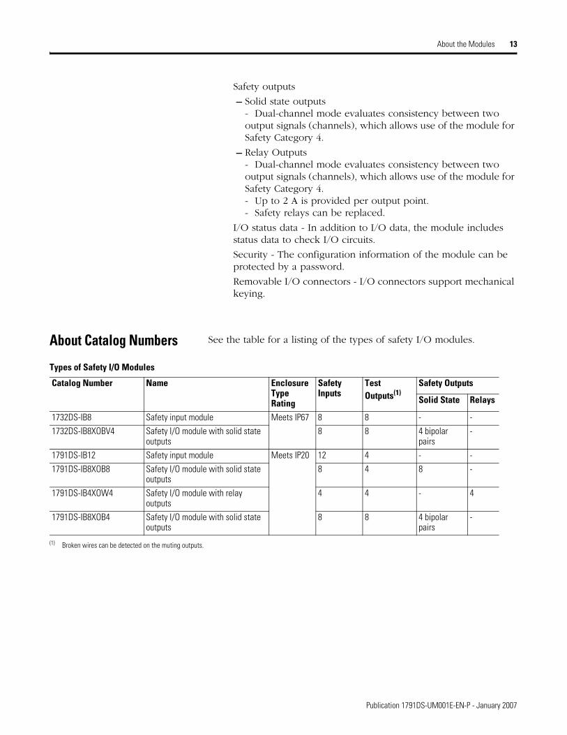
About Catalog Numbers See the table for a listing of the types of safety I/O modules.
Types of Safety I/O Modules
Catalog Number Name Enclosure Type Rating
Safety Inputs
Test Outputs(1)
Safety Outputs
Solid State Relays
1732DS-IB8 Safety input module Meets IP67 8 8 - -1732DS-IB8XOBV4 Safety I/O module with solid state
outputs8 8 4 bipolar
pairs-
1791DS-IB12 Safety input module Meets IP20 12 4 - -1791DS-IB8XOB8 Safety I/O module with solid state
outputs8 4 8 -
1791DS-IB4XOW4 Safety I/O module with relay outputs
4 4 - 4
1791DS-IB8XOB4 Safety I/O module with solid state outputs
8 8 4 bipolarpairs
-
(1) Broken wires can be detected on the muting outputs.
Publication 1791DS-UM001E-EN-P - January 2007
14 About the Modules
About CIP Safety in DeviceNet Safety Architectures
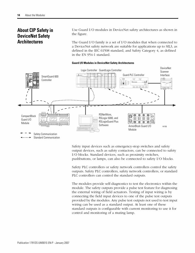
Use Guard I/O modules in DeviceNet safety architectures as shown in the figure.
The Guard I/O family is a set of I/O modules that when connected to a DeviceNet safety network are suitable for applications up to SIL3, as defined in the IEC 61508 standard, and Safety Category 4, as defined in the EN 954-1 standard.
Guard I/O Modules in DeviceNet Safety Architectures
Safety input devices such as emergency-stop switches and safety output devices, such as safety contactors, can be connected to safety I/O blocks. Standard devices, such as proximity switches, pushbuttons, or lamps, can also be connected to safety I/O blocks.
Safety PLC controllers or safety network controllers control the safety outputs. Safety PLC controllers, safety network controllers, or standard PLC controllers can control the standard outputs.
The modules provide self-diagnostics to test the electronics within the module. The safety outputs provide a pulse test feature for diagnosing the external wiring of field actuators. Testing of input wiring is by connecting the field input devices to one of the pulse test outputs provided by the modules. Any pulse test outputs not used to test input wiring can be used as a standard output. At least one of these standard outputs is configurable with current monitoring to use it for control and monitoring of a muting lamp.
44196
Logix Controller GuardLogix Controller
Guard PLC Controller
ArmorBlock Guard I/O Module
CompactBlockGuard I/O Module
RSNetWorx, RSLogix 5000, and RSLogixGuard Plus Software
SmartGuard 600Controller
Safety CommunicationStandard Communication
DeviceNet Scanner Interface
Publication 1791DS-UM001E-EN-P - January 2007

About the Modules 15
The modules also allow configuration of input points as dual inputs, and configuration of output points as dual outputs. The module performs internal diagnostics on I/O channels configured to operate in Dual mode.
Any discrepancy results in a safety state and status generated for the master. Configuration of DeviceNet Guard I/O modules is via software using either the network configuration tool, RSNetWorx for DeviceNet Safety software, or the PLC programming tool, RSLogix 5000 software.
Identify Major Parts of the Modules
See the figures that show major parts of the modules.
1791DS-IB4XOW4 Module Identification
1791DS-IB8XOB8 Module Identification
Node Address Switches LED Indicators Safety Relay
I/O Connections 44195
CommunicationConnector
1791DS-IB8XOB8
MS NS LO CK IN
PWROUTPWR0 1 2 3 4 5 6 70 1 2 3 4 5 6 7
CompactBlock
8 Inputs - 8 Outputs 24VDC
Node Address Switches LED Indicators
Communication Connector
I/O Connectors44091
Publication 1791DS-UM001E-EN-P - January 2007

16 About the Modules
1791DS-IB12 Module Identification
1791DS-IB8XOBV4 Module Identification
MS NS LO CK IN
PWR 0 1 2 3 4 5 6 78 9 10 11
CompactBlock
12 Inputs 24VDC1791DS-IB12
Node Address Switches LED Indicators
Communication Connector
I/O Connectors44091
NODEADR
8 2
46
08 2
46
0
X1X10
Node Address Switches
LED Indicators
I/O Connectors (input)44224
Communication Connector
LED IndicatorsPower Connector I/O Connectors (output)
Publication 1791DS-UM001E-EN-P - January 2007

About the Modules 17
1732DS-IB8 Module Identification
1732DS-IB8XOBV4 Module Identification
44123
Communication Connector
Node Address Switches
I/O PowerInputs
LED Indicators FE
Communication Connector
Node Address SwitchesOutputs
InputsI/O Power
44122
LED Indicators FE
Publication 1791DS-UM001E-EN-P - January 2007

18 About the Modules
1791DS-IB16 Module Identification
NC NC
NODEADR
8 2
46
08 2
46
0
X1X10
FE I8 I9 T8 T9 I10 I11 T10 T11M
1791DS- IB16
16 INPUTS 24 Vdc
FE I0 I1 T0 T1 I2 I3 T2 T3M I4 I5 T4 T5 I6 I7 T6 T7M
I12 I13 T12 T13 I14 I15 T 14 T15M
Node Address Switches
LED Indicators
I/O Connectors (input)44118
Communication Connector
LED IndicatorsPower Connector I/O Connectors (input)
Publication 1791DS-UM001E-EN-P - January 2007

Chapter 2
Understand the Operation of Safety Functions
What This Chapter Contains Read this chapter for information related to the safety functions of the modules. Also included is a brief overview on international standards and directives that you should be familiar with.
Safety I/O Modules The following status is treated as the safety state by the safety I/O modules.
Safety outputs: off
Safety input data to network:off
Safety Status
The module is designed for use in applications where the safety state is when the outputs turn off.
Self-diagnostic Functions
Self-diagnostics are performed when the power is turned on and periodically during operation. If an error occurs, it is treated as a fatal error, the red module status (MS) indicator lights, and the safety outputs and output data to the network turn off.
Output Off Input
Inputs to Network OffDeviceNet Network
Safety Status
44076
19 Publication 1791DS-UM001E-EN-P - January 2007

20 Understand the Operation of Safety Functions
Configuration Lock
After configuration data has been downloaded and verified, the configuration data within the module can be protected either by using RSNetWorx for DeviceNet or RSLogix 5000 software.
If the data is protected, the lock indicator on the front panel lights in solid yellow. If the data is not protected, the lock indicator on the front panel flashes in yellow.
Safety Inputs Read this section for information about safety inputs.
Test Pulse from Test Output
A test output is used in combination with a safety input. Specify the corresponding-test output terminal to use as the test source.
Publication 1791DS-UM001E-EN-P - January 2007
Understand the Operation of Safety Functions 21
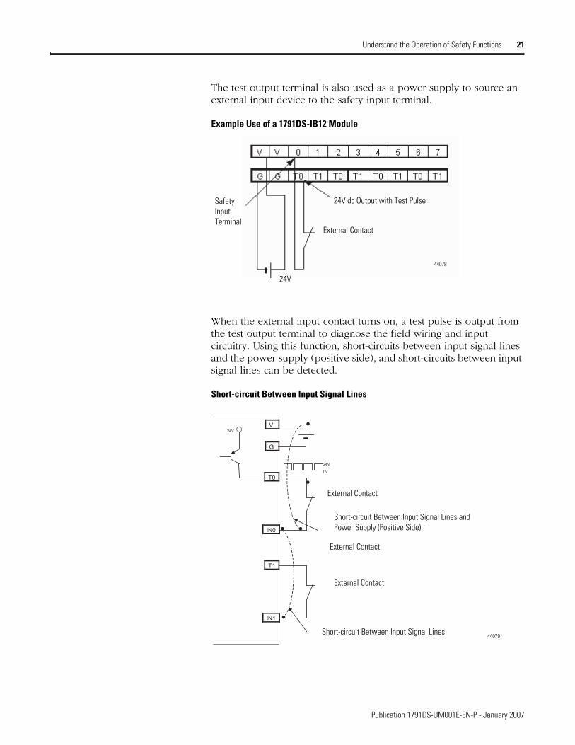
The test output terminal is also used as a power supply to source an external input device to the safety input terminal.
Example Use of a 1791DS-IB12 Module
When the external input contact turns on, a test pulse is output from the test output terminal to diagnose the field wiring and input circuitry. Using this function, short-circuits between input signal lines and the power supply (positive side), and short-circuits between input signal lines can be detected.
Short-circuit Between Input Signal Lines
24V dc Output with Test Pulse
External Contact
Safety Input Terminal
24V
44078
T0
IN0
�
24V
0V
24V
T1
IN1
V
G
�
�
� �
�
External Contact
Short-circuit Between Input Signal Lines and Power Supply (Positive Side)
External Contact
External Contact
Short-circuit Between Input Signal Lines44079
Publication 1791DS-UM001E-EN-P - January 2007

22 Understand the Operation of Safety Functions
If an error is detected, safety input data and safety input status turn off.
Normal Operation and Fault Detection
24V
0V
ON
OFF
ON
OFF
ON
OFF
ON
OFF
24V
0V
ON
OFF
ON
OFF
ON
OFF
ON
OFF
Normal Operation
Exte rnal Device
Input Terminal 0
Safety Input 0
Fault Detection
Safety InputStatus 0
Remote I/OData
TO
External Device
Input Terminal 0
Safety Input 0
Safety InputStatus 0
Remote I/OData
TO
FaultDetected
Publication 1791DS-UM001E-EN-P - January 2007

Understand the Operation of Safety Functions 23
Set Dual-channel Mode and Discrepancy Time
The consistency between signals on two channels can be evaluated. Either equivalent or complementary can be selected. This function monitors the time during which there is a discrepancy in the logic between the two channels set as dual channels.
If the length of the discrepancy exceeds the set discrepancy time (0…65,530 ms in increments of 10 ms), the safety input data and the individual-safety input status turns off for both inputs.
The following table shows the relation between terminal input status and remote I/O data.
IMPORTANT The dual-channel function is used with two consecutive inputs that start from even input numbers such as inputs 0 and 1, inputs 2 and 3, and inputs 4 and 5.
Terminal Input Status and Remote I/O Data
Dual-channel Mode Input Terminal Remote I/O Data Meaning of Data and StatusIN0 IN1 Safety Input 0 Safety Input 1 Status of
Safety Input 0Status of Safety Input 1
Dual-channels, Equivalent
OFF OFF OFF OFF ON ON OFF, normal (OK)OFF ON OFF OFF OFF OFF OFF, faultON OFF OFF OFF OFF OFF OFF, faultON ON ON ON ON ON ON, normal (OK)
Dual-channels, Complementary
OFF OFF OFF ON OFF OFF OFF, faultOFF ON OFF ON ON ON OFF, normal (OK)ON OFF ON OFF ON ON ON, normal (OK)ON ON OFF ON OFF OFF OFF, fault
Publication 1791DS-UM001E-EN-P - January 2007
24 Understand the Operation of Safety Functions
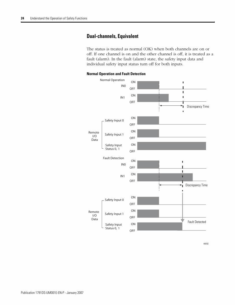
Dual-channels, Equivalent
The status is treated as normal (OK) when both channels are on or off. If one channel is on and the other channel is off, it is treated as a fault (alarm). In the fault (alarm) state, the safety input data and individual safety input status turn off for both inputs.
Normal Operation and Fault Detection
ON
OFF
ON
OFF
ON
OFF
ON
OFF
ON
OFF
ON
OFF
ON
OFF
Normal Operation
IN1
Safety Input 1
Safety Input 0
Fault Detection
Safety InputStatus 0, 1
Remote I/O
Data
IN0
IN1
IN0
ON
OFF
ON
OFF
ON
OFF
Safety Input 1
Safety Input 0
Safety InputStatus 0, 1
Remote I/O
Data
44092
Discrepancy Time
Discrepancy Time
Fault Detected
Publication 1791DS-UM001E-EN-P - January 2007

Understand the Operation of Safety Functions 25
Dual-channels, Complementary
The status is treated as normal (OK) when one channel is on and the other channel is off. When both channels are on or both channels are off, it is treated as a fault (alarm). In the fault (alarm) state, safety input 0 is off and safety input 1 is off, and the safety input status turns off for both inputs.
Normal Operation and Fault Detection
ON
OFF
ON
OFF
ON
OFF
ON
OFF
ON
OFF
ON
OFF
ON
OFF
Normal Operation
IN1
Safety Input 1
Safety Input 0
Fault Detection
Safety InputStatus 0, 1
Remote I/O
Data
IN0
IN1
IN0
ON
OFF
ON
OFF
ON
OFF
Safety Input 1
Safety Input 0
Safety InputStatus 0, 1
Remote I/O
Data
Time
44093
Fault Detected
Discrepancy Time
Discrepancy Time
Publication 1791DS-UM001E-EN-P - January 2007
26 Understand the Operation of Safety Functions
Fault Recovery
If an error is detected, the safety input data remains in the off state. The procedure for activating the safety input data again is as follows.
1. Remove the cause of the error.
2. Turn off the safety input.
The safety input status turns on after the input-error latch time has elapsed. The I/O indicator (red) turns off. The input data can now be controlled.
Input Delays
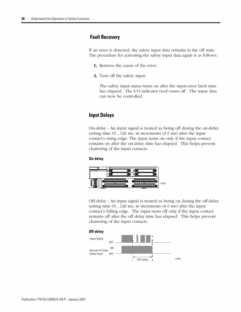
On-delay - An input signal is treated as being off during the on-delay setting time (0…126 ms, in increments of 6 ms) after the input contact’s rising edge. The input turns on only if the input contact remains on after the on-delay time has elapsed. This helps prevent chattering of the input contacts.
On-delay
Off-delay - An input signal is treated as being on during the off-delay setting time (0…126 ms, in increments of 6 ms) after the input contact’s falling edge. The input turns off only if the input contact remains off after the off delay time has elapsed. This helps prevent chattering of the input contacts.
Off-delay
44094
OFF
ON
OFFSafety Input
Input Signal
OFF-delay
Remote I/O Data
44095
Publication 1791DS-UM001E-EN-P - January 2007

Understand the Operation of Safety Functions 27
Safety Outputs Read this section for information about safety outputs.
Safety Output with Test Pulse
When the output is on, the test pulse is turned off in a cycle for a period of time as shown in the the table and figure.
Using this function, short-circuits between output signal lines and the power supply (positive side) and short-circuits between output signal lines can be detected. If an error is detected, the safety output data and individual-safety output status turns off.
Test Pulse in a Cycle
Pulse Width and Period for X and Y
Attribute 1791DS-IB8XOB8 1791DS-IB8XOBV4, 1732DS-IB8XOBV4
Pulse width, X 700 us 500 us
Pulse period,Y 648 ms 600 ms
IMPORTANT To prevent the test pulse from causing the connected device to malfunction, pay careful attention to the input response time of the device.
44096XY
OUT ON
OFF
Publication 1791DS-UM001E-EN-P - January 2007
28 Understand the Operation of Safety Functions
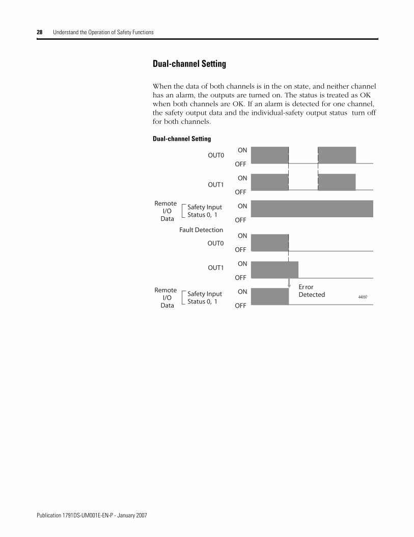
Dual-channel Setting
When the data of both channels is in the on state, and neither channel has an alarm, the outputs are turned on. The status is treated as OK when both channels are OK. If an alarm is detected for one channel, the safety output data and the individual-safety output status turn off for both channels.
Dual-channel Setting
ON
OFF
ON
OFF
ON
OFF
OUT1
OUT0
Fault Detection
Safety InputStatus 0, 1
Remote I/O
Data
OUT1
OUT0
Safety InputStatus 0, 1
Remote I/O
Data
ON
OFF
ON
OFF
ON
OFF
Er rorDetected 44097
Publication 1791DS-UM001E-EN-P - January 2007
Understand the Operation of Safety Functions 29
Fault Recovery
If a fault is detected, the safety output remains in the off state. The procedure for activating the safety output data again is as follows.
1. Remove the cause of the error.
2. Turn off the safety output or outputs.
The safety output status turns on when the output-error latch time has elapsed. The I/O indicator (red) turns off. The output data can now be controlled.
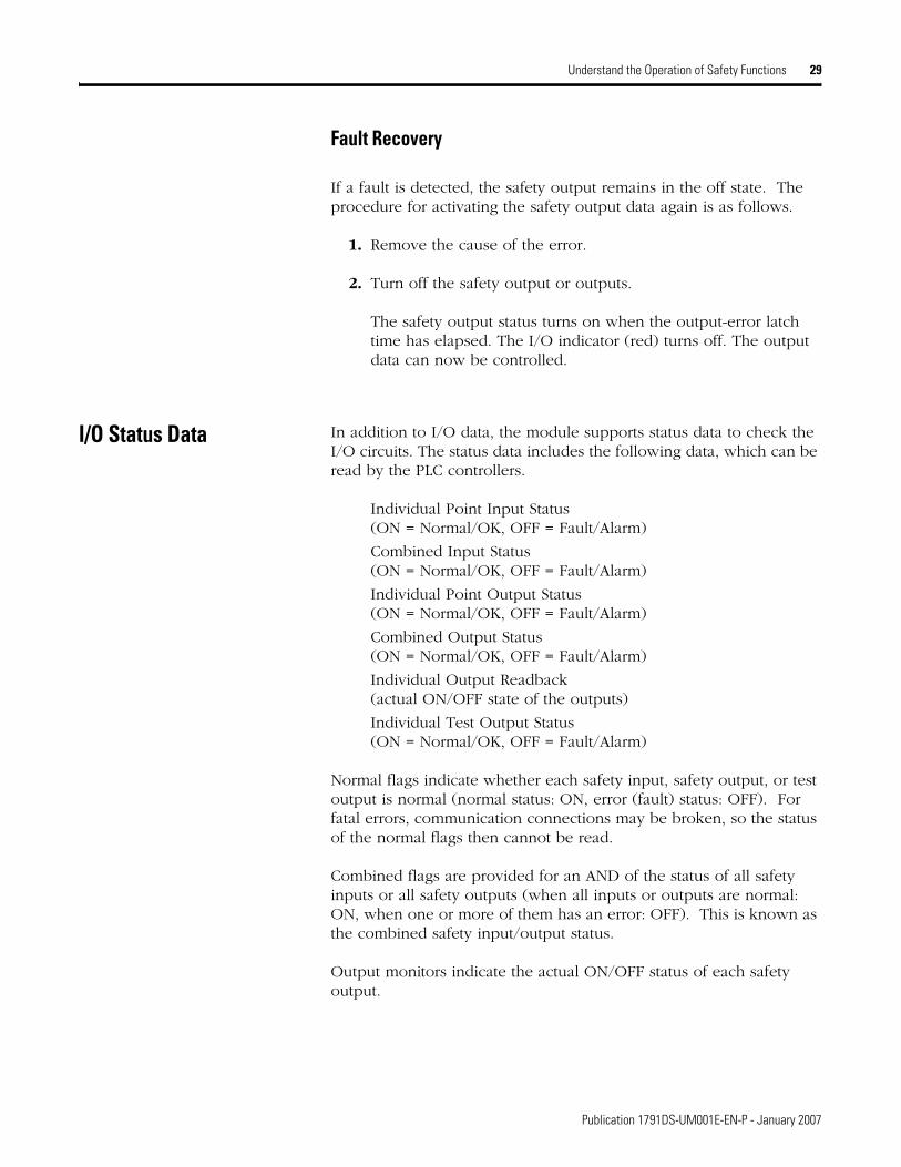
I/O Status Data In addition to I/O data, the module supports status data to check the I/O circuits. The status data includes the following data, which can be read by the PLC controllers.
Individual Point Input Status (ON = Normal/OK, OFF = Fault/Alarm)
Combined Input Status (ON = Normal/OK, OFF = Fault/Alarm)
Individual Point Output Status (ON = Normal/OK, OFF = Fault/Alarm)
Combined Output Status (ON = Normal/OK, OFF = Fault/Alarm)
Individual Output Readback (actual ON/OFF state of the outputs)
Individual Test Output Status (ON = Normal/OK, OFF = Fault/Alarm)
Normal flags indicate whether each safety input, safety output, or test output is normal (normal status: ON, error (fault) status: OFF). For fatal errors, communication connections may be broken, so the status of the normal flags then cannot be read.
Combined flags are provided for an AND of the status of all safety inputs or all safety outputs (when all inputs or outputs are normal: ON, when one or more of them has an error: OFF). This is known as the combined safety input/output status.
Output monitors indicate the actual ON/OFF status of each safety output.
Publication 1791DS-UM001E-EN-P - January 2007

30 Understand the Operation of Safety Functions
Controlling Devices See the table for sample requirements for controlling devices.
ATTENTION Use appropriate devices as indicated in the Controlling Devices - Sample Requirements table. Serious injury may occur due to loss of safety functions.
Controlling Devices - Sample Requirements
Device Requirement Allen-Bradley Bulletin Safety ComponentsEmergency stop switches
Use approved devices with direct opening mechanisms complying with IEC/EN 60947-5-1.
Bulletin 800F, 800T
Door interlocking switches,limit switches
Use approved devices with direct opening mechanisms complying with IEC/EN 60947-5-1 and capable of switching microloads of 24V dc 3 mA.
Bulletin 440K, 440G, 440H for interlock switchBulletin 440P, 802T for limit switch
Safety sensors Use approved devices complying with the relevant product standards, regulations, and rules in the country where used.
Any Guardmaster product
Relays with forcibly- guided contacts,contactors
Use approved devices with forcibly-guided contacts complying with EN 50205. For feedback purposes, use devices with contacts capable of switching micro loads of 24V dc 3 mA.
Bulletin 700S, 100S
Other devices Evaluate whether devices used are appropriate to satisfy the requirements of safety category levels.
-
Publication 1791DS-UM001E-EN-P - January 2007
Understand the Operation of Safety Functions 31
Safety Precautions
Legislation and Standards Read this section to familiarize yourself with related legislation and standards information. Relevant international standards include the following:
IEC 61508 (SIL 1-3)
IEC 61131-2
IEC 60204-1
IEC 61000-6-2
IEC 61000-6-4
The modules received the following certification from ODVA, when product is marked.
DeviceNet Conformance Test
DeviceNet Safety Conformance Test
ATTENTION As serious injury may occur due to loss of required safety function, follow these safety precautions.
Do not use test outputs of the modules as safety outputs.
Do not use DeviceNet standard I/O data or explicit message data as safety data.
Do not use LED indicators on the safety I/O modules for safety operations.
Do not connect loads beyond the rated value to the safety outputs.
Wire the safety I/O modules properly so that 24V dc line does not touch the safety outputs accidentally or unintentionally.
Ground the 0V line of the power supply for external output devices so that the devices do not turn on when the safety output line is grounded.
Clear previous configuration data before connecting devices to the network.
Set suitable node addresses before connecting devices to the network.
Perform user testing and confirm that all of the device configuration data and operation is correct before starting system operation.
When replacing a device, configure the replacement device suitably and confirm that it operates correctly.
When installing or replacing modules, clear any previous configuration before connecting input or output power to the device.
Publication 1791DS-UM001E-EN-P - January 2007

32 Understand the Operation of Safety Functions
Europe
In Europe, Guard I/O modules are subject to the European Union (EU) Machinery Directive Annex IV, B, Safety Components, items 1 and 2. The type approval of TUV-Rheinland addresses compliance to applicable requirements of the following directives and standards:
EU legislation
Machinery Directive 98/37/EC
Low-voltage Directive 73/23/EEC
EMC Directive 89/336/EEC
European standards
EN 61508 (SIL1-3)
EN 954-1 (Category 4, 3, 2, 1, B)
EN 61131-2
EN 418
EN 60204-1
IEC 61000-6-2
IEC 61000-6-4
North America
In North America, the TUV-Rheinland type approval includes Guard I/O compliance to the relevant standards and related information including the following:
U.S. standards - ANSI RIA15.06, ANSI B11.19, NFPA 79
The modules are UL-certified functionally safe and carry the NRGF label, when product is marked.
The modules received UL Listing to standards of U.S. and Canada including the following, when product is marked:
UL 508, UL 1604, CSA 22.1 No.14, CSA 22.2 No. 213 (for 1791DS-IB12, 1791DS-IB8XOB8, 1791DS-IB8XOBV4, 1732-IB8XOBV4, 1732-IB modules)
UL 508, CSA 22.1 No. 14 (for 1791DS-IB4XOW4 modules)
Publication 1791DS-UM001E-EN-P - January 2007

Understand the Operation of Safety Functions 33
Japan
In Japan, type test requirements are provided in Article 44 of the Industrial Safety and Health Law. These requirements apply to complete systems and cannot be applied to a module by itself. Accordingly, to use the module in Japan as a safety device for press machine or shearing tool pursuant to Article 42 of the above-mentioned law, it is necessary to apply for testing of the entire system.
EC Directives DeviceNet products conform to the EMC Directive and Low-voltage Directive.
EMC Directive
Rockwell Automation devices that comply with EC directives also conform to the related EMC standards so that they can more easily be built into other devices or the overall machine. The actual products have been checked for conformity to EMC standards. Whether they conform to the standards in the system used by the customer, however, must be confirmed by the customer.
EMC-related performance of Rockwell Automation devices that comply with EC directives vary depending on the configuration, wiring, and other conditions of the equipment or control panel in which the Rockwell Automation devices are installed. The customer must, therefore, perform the final check to confirm that devices and the overall machine conform to EMC standards.
Compliance with EC Directives
DeviceNet products that comply with EC directives must be installed as follows.
All Type IP20 DeviceNet units must be installed within control panels.
Use reinforced insulation or double insulation for the dc power supplies used for the communication power supply, internal- circuit power supply, and the I/O power supplies.
Publication 1791DS-UM001E-EN-P - January 2007

34 Understand the Operation of Safety Functions
DeviceNet products that comply with EC directives also conform to the Common Emission Standard (EN 50081-2). Radiated emission characteristics (10-m regulations) may vary depending on the configuration of the control panel used, other devices connected to the control panel, wiring, and other conditions. You must confirm that the overall machine or equipment complies with EC directives.
DeviceNet products that comply with EC directives must have configurations with less than 30 m (98.43 ft) of I/O wiring and less than 10 m (32.81 ft) of power supply wiring, which applies to the 1791DS-IB12, 1791DS-IB8XOB8, and 1791DS-IB4XOW4 modules.
The following examples show how to reduce noise.
Reduce electrical noise from the communication cable by installing a ferrite core on the communication cable within 10 cm (3.93 in.) of the DeviceNet master unit.
Ferrite Core (Data Line Filter) LF130B (manufactured by Easy Magnet Co.)
Ferrite Core
Wire the control panel with cables that are as short as possible and ground to 100 or less.
Keep DeviceNet communication cables as short as possible and ground to 100 or less.
Impedance Specifications
Impedance Value25 MHz 100 MHz156 250
31522-M
13(0.51)
29(1.14)
30(1.18)
33(1.30)
mm(in.)
Publication 1791DS-UM001E-EN-P - January 2007

Chapter 3
Install and Connect Your Modules
What This Chapter Contains This chapter explains these general procedures for module use:
Install the module in the control panel.
Wire I/O power and cables.
Connect communication connectors.
Set the node address.
Configure the system, making settings for the module.
The communication baud rate of the entire network is determined by the communication baud rate of the master unit. The communication baud rate does not need to be set for each module.
ATTENTION Test Output points configured as Pulse Test or Power Supply become active whenever you apply network power and input power to the module. These configured functions are independent of the I/O connections to the module.
You can configure Test Outputs as Standard when they are used as standard outputs. You can connect Actuators to Test Output points that are expecting a Standard configuration.
If a module with Test Outputs configured as Pulse Test or Power Supply is incorrectly installed in an application where actuators are connected to these Test Output points, the actuators will be activated when network power and input power are applied.
To prevent this possibility, use the following procedures:
When installing a module, be sure that the module is correctly configured for the application or in the out-of-box condition before applying input power.When replacing a module, be sure that the module is correctly configured for the application or in the out-of-box condition before applying input power.Reset modules to their out-of-box condition when removing them from an application.Be sure that all modules in replacement stock are in their out-of-box condition.
35 Publication 1791DS-UM001E-EN-P - January 2007
36 Install and Connect Your Modules
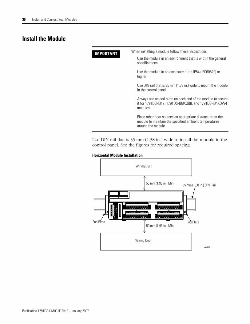
Install the Module
Use DIN rail that is 35 mm (1.38 in.) wide to install the module in the control panel. See the figures for required spacing.
Horizontal Module Installation
IMPORTANT When installing a module follow these instructions.
Use the module in an environment that is within the general specifications.
Use the module in an enclosure rated IP54 (IEC60529) or higher.
Use DIN rail that is 35 mm (1.38 in.) wide to mount the module in the control panel.
Always use an end plate on each end of the module to secure it for 1791DS-IB12, 1791DS-IB8XOB8, and 1791DS-IB4XOW4 modules.
Place other heat sources an appropriate distance from the module to maintain the specified ambient temperatures around the module.
44088
Wiring Duct
Wiring Duct
End Plate End Plate
50 mm (1.96 in.) Min
50 mm (1.96 in.) Min
35 mm (1.38 in.) DIN Rail
Publication 1791DS-UM001E-EN-P - January 2007
Install and Connect Your Modules 37
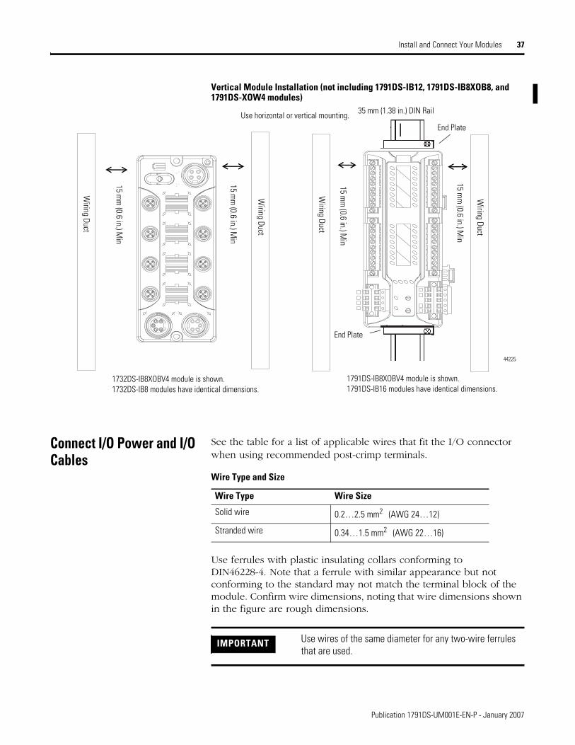
Vertical Module Installation (not including 1791DS-IB12, 1791DS-IB8XOB8, and 1791DS-XOW4 modules)
Connect I/O Power and I/O Cables
See the table for a list of applicable wires that fit the I/O connector when using recommended post-crimp terminals.
Use ferrules with plastic insulating collars conforming to DIN46228-4. Note that a ferrule with similar appearance but not conforming to the standard may not match the terminal block of the module. Confirm wire dimensions, noting that wire dimensions shown in the figure are rough dimensions.
Wiring Duct
Wiring Duct
Wiring Duct
15 mm
(0.6 in.) Min
15 mm
(0.6 in.) Min
15 mm
(0.6 in.) Min
35 mm (1.38 in.) DIN Rail Use horizontal or vertical mounting.
44225
Wiring Duct
15 mm
(0.6 in.) Min
1791DS-IB8XOBV4 module is shown. 1791DS-IB16 modules have identical dimensions.
1732DS-IB8XOBV4 module is shown. 1732DS-IB8 modules have identical dimensions.
End Plate
End Plate
Wire Type and Size
Wire Type Wire Size
Solid wire 0.2…2.5 mm2 (AWG 24…12)
Stranded wire 0.34…1.5 mm2 (AWG 22…16)
IMPORTANT Use wires of the same diameter for any two-wire ferrules that are used.
Publication 1791DS-UM001E-EN-P - January 2007

38 Install and Connect Your Modules
Ferrule for One Wire and Two Wires
Reference Specifications (Product Specifications of Phoenix Contact)
Ferrule Model
Wire Dimensions Ferrule SpecificationsCross-
sectional Area of
Conductor (mm2)
AWG
Removed Length of Insulation mm (in.)
Entire Length L1 mm (in.)
Length of Metal Part
L2mm (in.)
Inner Diameter of Conductor
D1 mm (in.)
Inner Diameter of Insulation Cover D2 mm (in.)
Dimensions
For O
ne W
ire AI 0.34-8TQ 0.34 22 10 (0.39) 12.5 (0.49) 8 (0.31) 0.8 (0.03) 2.0 (0.08)
See figure for one wire.
AI 0.5-8WH 0.5 20 10 (0.39) 14 (0.55) 8 (0.31) 1.1 (0.04) 2.5 (0.09)AI 0.75-8GY 0.75 18 10 (0.39) 14 (0.55) 8 (0.31) 1.3 (0.05) 2.8 (0.11)AI 1.0-8RD 1.0 18 10 (0.39) 14 (0.55) 8 (0.31) 1.5 (0.06) 3.0 (0.12)AI 1.5-8BK 1.5 16 10 (0.39) 14 (0.55) 8 (0.31) 1.8 (0.07) 3.4 (0.13)
For T
wo
Wire
s
AI-TWIN 2 x 0.5-8WH 2 x 0.5 - 10 (0.39) 15 (0.59) 8 (0.31) 1.5 (0.06)
2.5/4.7
See figure for two wires.
(0.09/0.18)AI-TWIN 2 x 0.75-8GY
2 x 0.75 - 10 (0.39) 15 (0.59) 8 (0.31) 1.8 (0.07)2.8/5.0
(0.11/0.19)AI-TWIN 2 x 1-8RD
2 x 1 - 10 (0.39) 15 (0.59) 8 (0.31) 2.05 (0.080)3.4/5.4
(0.13/0.21)
44089
Insulating Collar Insulating Collar
For One Wire For Two Wires
Publication 1791DS-UM001E-EN-P - January 2007

Install and Connect Your Modules 39
Use a Phoenix Contact crimping tool (model CRIMPFOX UD6) for the ferrules.
Connect Communication Connectors
Colored stickers on the communication connector match the colors of the wires to be inserted. Check that the colors of the wires and stickers match when wiring the connectors. The colors are as follows.
The internal power for the module is supplied from the communication power supply (V+, V-).
IMPORTANT When crimping connection cables, follow these instructions.
Use ferrules when wiring cables.
Note that I/O connectors are detachable.
Tighten the screws on the I/O connector to 0.25…0.3 Nm (2.16…2.59 lb-in).
Since the I/O connector has a structure that helps prevent incorrect wiring, make connections at the specified locations corresponding to the terminal numbers.
Do not remove the shield from the module before wiring.
Always remove the shield after completing wiring to be sure of proper heat dispersion.
Colors and Signals
Color Signal
Red Power cable positive side (V+)
White High side of communication data (CAN_H)
- Shield
Blue Low side of communication data (CAN_L)
Black Power cable negative side (V-)
IMPORTANT When connecting a communication connector with the module, tighten the screws on the communication connector to 0.25…0.3 Nm (2.16…2.59 lb-in).
Publication 1791DS-UM001E-EN-P - January 2007
Pu
40 Install and Connect Your Modules
blication 1791DS-UM001E-EN-P - January 2007
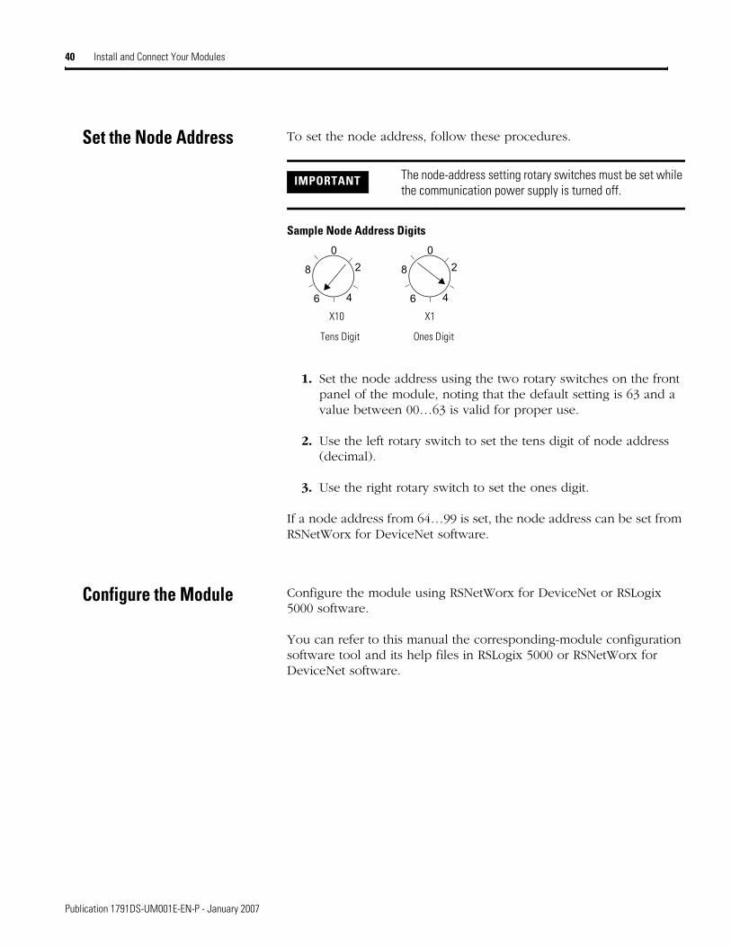
Set the Node Address To set the node address, follow these procedures.
Sample Node Address Digits
1. Set the node address using the two rotary switches on the front panel of the module, noting that the default setting is 63 and a value between 00…63 is valid for proper use.
2. Use the left rotary switch to set the tens digit of node address (decimal).
3. Use the right rotary switch to set the ones digit.
If a node address from 64…99 is set, the node address can be set from RSNetWorx for DeviceNet software.
Configure the Module Configure the module using RSNetWorx for DeviceNet or RSLogix 5000 software.
You can refer to this manual the corresponding-module configuration software tool and its help files in RSLogix 5000 or RSNetWorx for DeviceNet software.
IMPORTANT The node-address setting rotary switches must be set while the communication power supply is turned off.
Tens Digit Ones Digit
||
||
|
2
46
8
0 ||
||
|
2
46
8
0
X1X10

Chapter 4
Configure Modules in RSLogix 5000 Software
What This Chapter Contains This chapter provides information about how to configure your modules in RSLogix 5000 software.
Use the Help Button At the bottom of a dialog, click Help for information about how to complete entries on the dialog. At the bottom of a warning dialog, click Help to get information about that specific error.
Add Safety Modules to the I/O Configuration Tree
To add a safety module to the I/O configuration tree, follow this procedure.
1. From the I/O Configuration tree, right-click the 1756-DNB module, as shown in the figure, and select New Module.
From the I/O Configuration tree, right-click the 1756-DNB module and select New Module.
41 Publication 1791DS-UM001D-EN-P - January 2007

42 Configure Modules in RSLogix 5000 Software
You see the Select Module dialog with a list that includes Safety.
2. From the Select Module dialog, click the + next to Safety to see a list of safety modules.
From the Select Module dialog, click + next to Safety to see a list of modules.
A list of safety modules appears here.
Click Find if desired.
Publication 1791DS-UM001D-EN-P - January 2007
Configure Modules in RSLogix 5000 Software 43
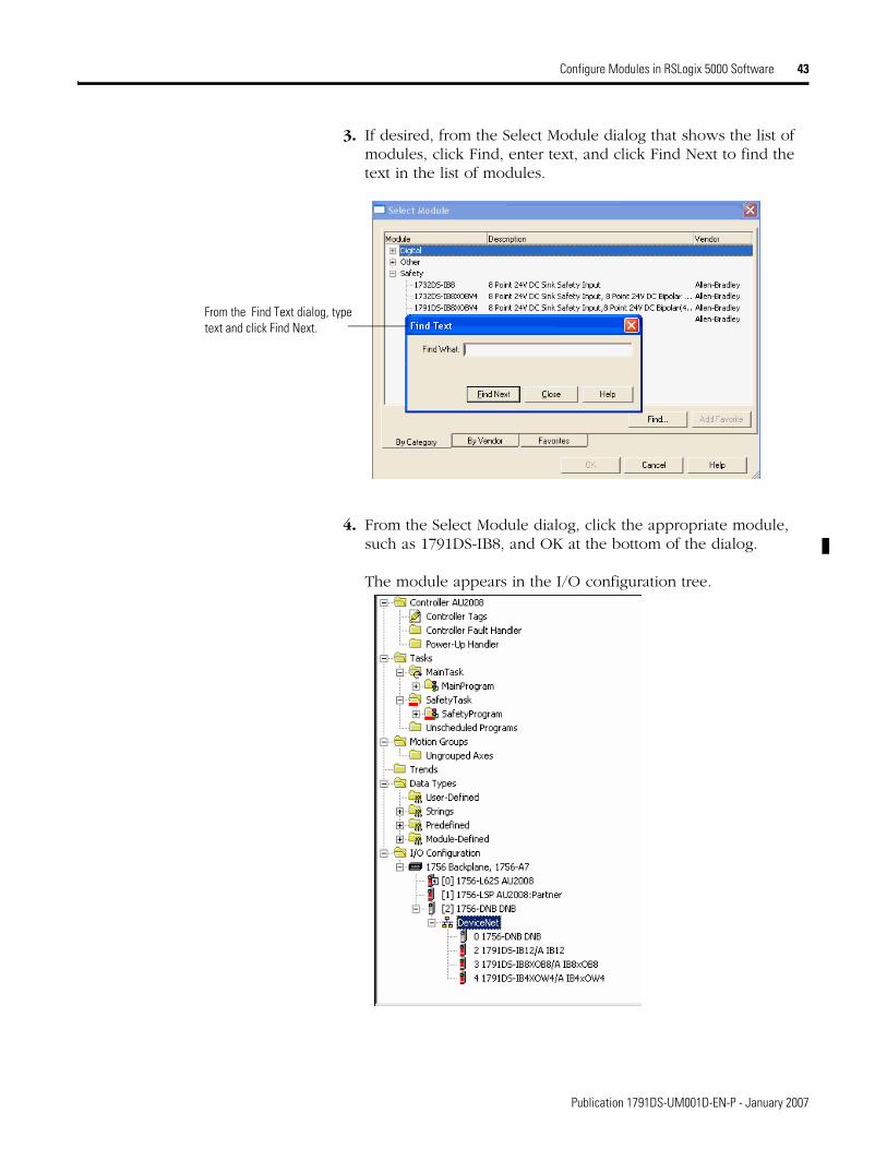
3. If desired, from the Select Module dialog that shows the list of modules, click Find, enter text, and click Find Next to find the text in the list of modules.
4. From the Select Module dialog, click the appropriate module, such as 1791DS-IB8, and OK at the bottom of the dialog.
The module appears in the I/O configuration tree.
From the Find Text dialog, type text and click Find Next.
Publication 1791DS-UM001D-EN-P - January 2007
44 Configure Modules in RSLogix 5000 Software
Use the Module Properties and General Dialogs
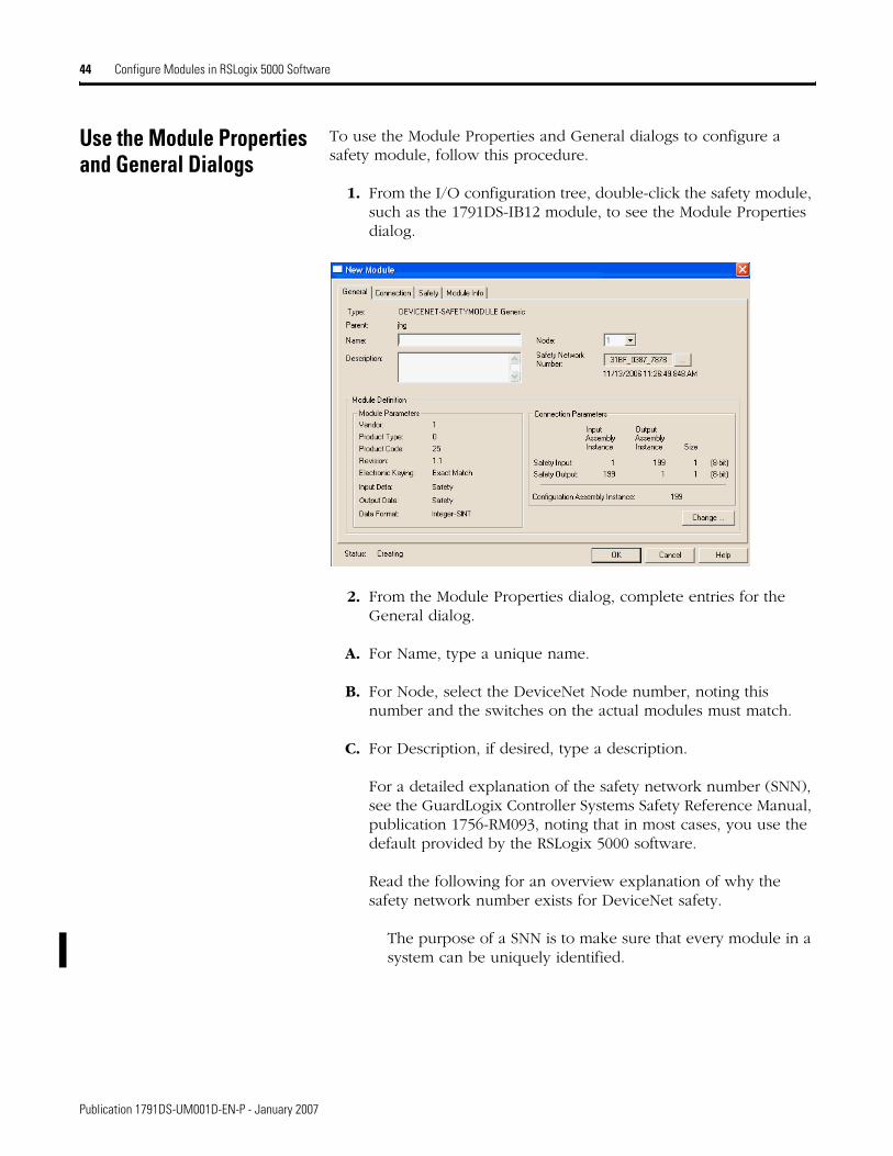
To use the Module Properties and General dialogs to configure a safety module, follow this procedure.
1. From the I/O configuration tree, double-click the safety module, such as the 1791DS-IB12 module, to see the Module Properties dialog.
2. From the Module Properties dialog, complete entries for the General dialog.
A. For Name, type a unique name.
B. For Node, select the DeviceNet Node number, noting this number and the switches on the actual modules must match.
C. For Description, if desired, type a description.
For a detailed explanation of the safety network number (SNN), see the GuardLogix Controller Systems Safety Reference Manual, publication 1756-RM093, noting that in most cases, you use the default provided by the RSLogix 5000 software.
Read the following for an overview explanation of why the safety network number exists for DeviceNet safety.
The purpose of a SNN is to make sure that every module in a system can be uniquely identified.
Publication 1791DS-UM001D-EN-P - January 2007
Configure Modules in RSLogix 5000 Software 45
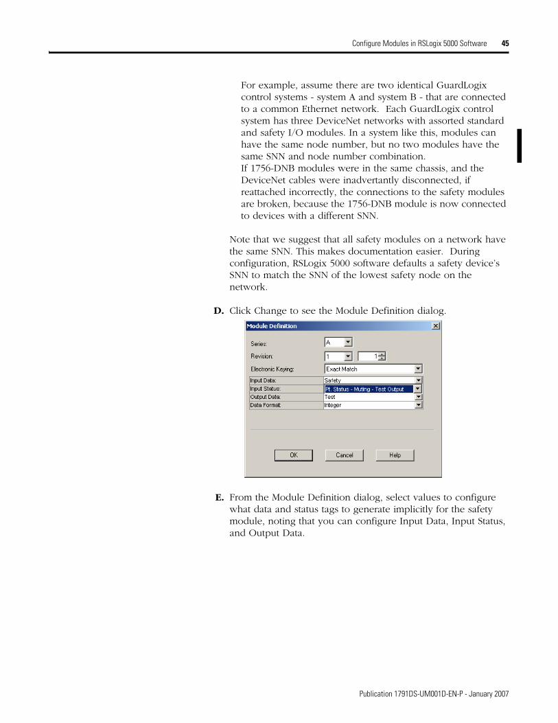
For example, assume there are two identical GuardLogix control systems - system A and system B - that are connected to a common Ethernet network. Each GuardLogix control system has three DeviceNet networks with assorted standard and safety I/O modules. In a system like this, modules can have the same node number, but no two modules have the same SNN and node number combination.If 1756-DNB modules were in the same chassis, and the DeviceNet cables were inadvertantly disconnected, if reattached incorrectly, the connections to the safety modules are broken, because the 1756-DNB module is now connected to devices with a different SNN.
Note that we suggest that all safety modules on a network have the same SNN. This makes documentation easier. During configuration, RSLogix 5000 software defaults a safety device’s SNN to match the SNN of the lowest safety node on the network.
D. Click Change to see the Module Definition dialog.
E. From the Module Definition dialog, select values to configure what data and status tags to generate implicitly for the safety module, noting that you can configure Input Data, Input Status, and Output Data.
Publication 1791DS-UM001D-EN-P - January 2007

46 Configure Modules in RSLogix 5000 Software
Input Data Options
Choose from these options:
Safety - Selecting Safety creates these tags for the target module:
– RunMode: Module mode
– ConnectionFaulted: Communications status
– Safety Data: Safety inputs from module
Safety-Readback - This selection is not available for input-only safety modules. Selecting Safety-Readback creates both safety and readback tags, with readback indicating the presence of 24V on the output terminal.
Small Safety - This selection is for 12-point safety input modules that use 8 or fewer safety inputs. The selection reduces the amount of data the 12-point module sends to the controller to improve network performance. Safety data and point status tags are created. Point status is diagnostic status for each of the 8 input points.
Publication 1791DS-UM001D-EN-P - January 2007
Configure Modules in RSLogix 5000 Software 47
Input Status Options
Choose from these options:
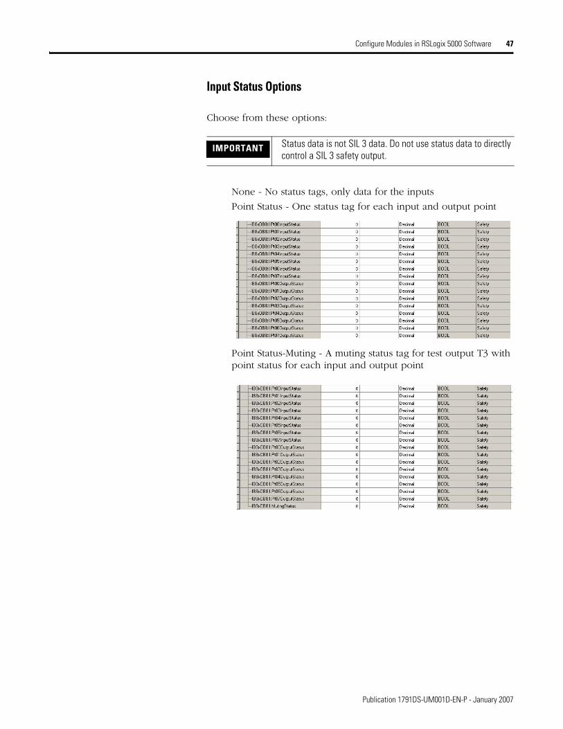
None - No status tags, only data for the inputs
Point Status - One status tag for each input and output point
Point Status-Muting - A muting status tag for test output T3 with point status for each input and output point
IMPORTANT Status data is not SIL 3 data. Do not use status data to directly control a SIL 3 safety output.
Publication 1791DS-UM001D-EN-P - January 2007

48 Configure Modules in RSLogix 5000 Software
Combined Status-Muting
– A single BOOL tag represents an AND of the status bits for all the input points. For example, if any input channel has a
fault, this bit goes LO.(1)
– A single BOOL tag represents an AND of the status bits for all
the output points.(1)
– A muting status tag for test output T3.
Point Status-Muting-Test Output
– Status tags for each of the input and output points.
– Muting status tag for test output T3.
– Status tags for each of the test outputs.
(1) When using combined status, use explicit messaging to read individual point status for diagnostic purposes.
Publication 1791DS-UM001D-EN-P - January 2007
Configure Modules in RSLogix 5000 Software 49
Output Data Options
Choose from these options.
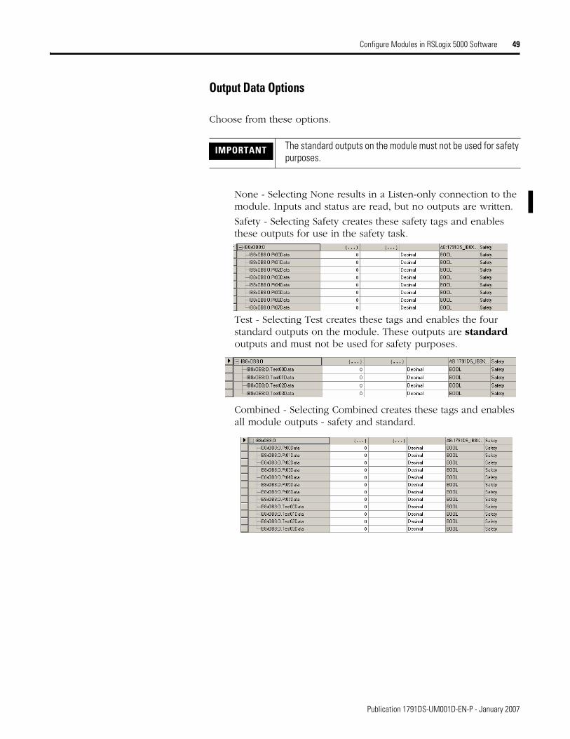
None - Selecting None results in a Listen-only connection to the module. Inputs and status are read, but no outputs are written.
Safety - Selecting Safety creates these safety tags and enables these outputs for use in the safety task.
Test - Selecting Test creates these tags and enables the four standard outputs on the module. These outputs are standard outputs and must not be used for safety purposes.
Combined - Selecting Combined creates these tags and enables all module outputs - safety and standard.
IMPORTANT The standard outputs on the module must not be used for safety purposes.
Publication 1791DS-UM001D-EN-P - January 2007

50 Configure Modules in RSLogix 5000 Software
Values and States of Tags
This table shows the values and states of the tags.
Safety denotes information the controller can use in safety-related functions. Standard denotes additional information that must not be relied on for safety functions.
Data DescriptionInput data Safety Input Data
SAFETYIndicates the ON/OFF status of each input terminal.
ON: 1 OFF: 0Combined Safety Input StatusSAFETY
An AND of the status of all input terminals.
All terminals are normal: 1
An error was detected in one or more input terminals: 0Individual Safety Input StatusSAFETY
Indicates the status of each input terminal.
Normal (OK): 1 Fault (Alarm): 0Combined Safety Output StatusSAFETY
An AND of the status of all safety output terminals.
All terminals are normal: 1
An error has been detected in one or more output terminals: 0Individual Safety Output StatusSAFETY
Indicates the status of each safety output terminal.
Normal (OK): 1 Fault (Alarm): 0Muting Lamp StatusSAFETY
Indicates the status when terminal T3 is configured as the muting lamp output.
Normal (OK)l: 1 Fault (Alarm): 0Output Readback STANDARD
Monitors the presence of 24V on the output terminal. Readback is ON (1) if 24V is on output terminal.
ON: 1 OFF: 0Individual Test Output StatusSTANDARD
Indicates the status of each of the test output terminals.
Normal (OK): 1 Fault (Alarm): 0
Output data Safety Output DataSAFETY
Controls the safety output.
ON: 1 OFF: 0Standard Output DataSTANDARD
Controls the test output when Test Output mode is set to a standard output.
ON: 1 OFF: 0
IMPORTANT Note that all status (diagnostic) data is considered to be standard data and must not directly control a SIL 3 safety output. There are settings where standard data is part of a safety tag. This is done to make communication more efficient and to reduce controller overhead.
Publication 1791DS-UM001D-EN-P - January 2007
Configure Modules in RSLogix 5000 Software 51
Work with the Safety Dialog
Read this for information about how to complete entries when you click Safety at the top of the Module Properties dialog.
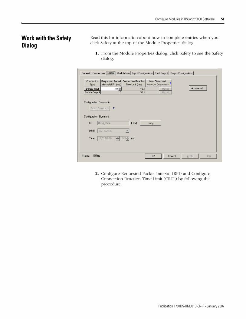
1. From the Module Properties dialog, click Safety to see the Safety dialog.
2. Configure Requested Packet Interval (RPI) and Configure Connection Reaction Time Limit (CRTL) by following this procedure.
Publication 1791DS-UM001D-EN-P - January 2007

52 Configure Modules in RSLogix 5000 Software
A. From the Safety dialog, click Advanced to see the Advanced Connection Reaction Time Limit Configuration dialog.
Make sure that input modules are set to match the need. The smallest input RPI allowed is 6 ms. Selecting small RPI's consumes network bandwidth and may cause nuisance trips because other devices can't get access to the network.
As an example, a safety input module with only ESTOP switches connected to it generally may work well with settings of 50…100 ms. An input module with a light curtain guarding a hazard may need the fastest response that is possible.
Selecting appropriate RPI's will result in a system with maximum (best) performance.
IMPORTANT You should always analyze each safety channel to determine what is appropriate. These examples are simply to convey concepts and should not be used as any kind of official recommendation.
We recommend that you keep the Timeout Multiplier and Network Delay Multiplier at their default values of 2 and 200.
See GuardLogix Controllers User Manual, publication number 1756-UM020, for more information about the CRTL.
Publication 1791DS-UM001D-EN-P - January 2007
Configure Modules in RSLogix 5000 Software 53
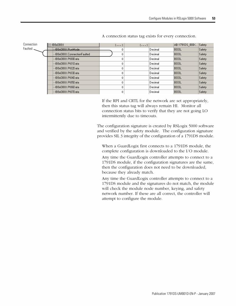
A connection status tag exists for every connection.
If the RPI and CRTL for the network are set appropriately, then this status tag will always remain HI. Monitor all connection status bits to verify that they are not going LO intermittently due to timeouts.
The configuration signature is created by RSLogix 5000 software and verified by the safety module. The configuration signature provides SIL 3 integrity of the configuration of a 1791DS module.
When a GuardLogix first connects to a 1791DS module, the complete configuration is downloaded to the I/O module.
Any time the GuardLogix controller attempts to connect to a 1791DS module, if the configuration signatures are the same, then the configuration does not need to be downloaded, because they already match.
Any time the GuardLogix controller attempts to connect to a 1791DS module and the signatures do not match, the module will check the module node number, keying, and safety network number. If these are all correct, the controller will attempt to configure the module.
Connection Faulted
Publication 1791DS-UM001D-EN-P - January 2007

54 Configure Modules in RSLogix 5000 Software
Work with the Input Configuration Dialog
See the table that shows typical safety input parameters, referring to Chapter 2 for related information.
Typical Safety Input Parameters
Parameter Name(1) Value Description
x Input Delay Time Off -> On
0…126 ms (in increments of 6 ms)
Filter time is for OFF to ON transition. Input must be high after input delay has elapsed before it is set logic 1.
x Input Delay TimeOn -> Off
0…126 ms (in increments of 6 ms)
Filter time is ON to OFF transition. Input must be low after input delay has elapsed before it is set logic 0.
x Input Point Mode Not Used The input is disabled. It remains logic 0 if 24V is applied to the input terminal. Safety Test Pulse Pulse testing is performed on this input circuit. A test source on the 1791DS
module must be used as the 24V source for this circuit. The test source is configured using the test source pulldown. The pulse test will detect shorts to 24V and channel-to-channel shorts to other inputs.
Safety A safety input is connected but there is no requirement for the 1791DS module to perform a pulse test on this circuit. An example is a safety device that performs its own pulse tests on the input wires, such as a light curtain.
Standard A standard device, such as a reset switch, is connected.x Safety Input Test Source None If pulse testing is being performed on an input point, then the test source that
is sourcing the 24V for the input circuit must be selected.
If the incorrect test source is entered, the result is pulse test failures on that input circuit.
Test Output 0Test Output 1Test Output 2Test Output 3
Test Output 4…7(2)
x Input Point Operation Type Single Channel Inputs are treated as single channel.Dual-channel Equivalent Inputs are treated as a dual-channel pair. The channels must match (be
equal) within the discrepancy time or a fault is generated. Dual-channel Complementary
Inputs are treated as a dual-channel pair. The channels must disagree (be opposite) within the discrepancy time or a fault is generated.
x Safety Input Error Latch Time
0…65,530 ms (in increments of 10 ms)
Default is 1000 ms. The purpose for latching input errors is to make sure that intermittent faults that may only exist for a few milliseconds are latched long enough to be read by the controller. The amount of time to latch the errors is based on the RPI, the safety task watchdog, and other application-specific variables.
(1) Parameters directly related to safety are marked with an X in the left column.
(2) There are eight test outputs on 1791DS-IB8XOBV4 modules.
Publication 1791DS-UM001D-EN-P - January 2007

Configure Modules in RSLogix 5000 Software 55
Follow this procedure to complete entries from the Input Configuration Dialog that you see when, from the top of the Module Properties dialog, you click Input Configuration.
1. For Point Operation, for Type, select one of these and a value for Discrepancy Time if set to Equivalent or Complementary:
Single Inputs are treated as single channels. Note that in many cases, dual-channel safety inputs are configured as two individual single channels. This does not affect pulse testing because it is handled on an individual channel basis.
Equivalent(1) Inputs are treated as a dual-channel pair. The channels must match within the discrepancy time or an error is generated.
Complementary(1)
Inputs are treated as a dual-channel pair. They must be in opposite states within the discrepancy time or an error is generated.
(1) Be aware that configuring discrepancy time on safety I/O modules masks input inconsistent faults from the safety controller.
Publication 1791DS-UM001D-EN-P - January 2007

56 Configure Modules in RSLogix 5000 Software
2. For Point Mode, select one of these for each point, referring to the Safety Input Parameters table for additional information:
Not Used - Safety input channel is disabled
Safety Pulse Test - Safety input is configured for pulse test operation
Safety - Safety input is used with a safety field device
Standard - Safety input has a standard field device wired to it
3. Complete entries, noting the following:
For each safety input on the module, you can define if the input will be pulse tested. If the inputs will be pulse tested, select which test source to use. Test sources, such as 0…3, correlate to the standard outputs, such as 0…3, on the module. Test sources, such as 0…7, correlate to standard outputs, such as 0…7, on 1791DS-IB8XOBV4 modules.
Off -> On and On -> Off delay times can be configured per channel with each channel specifically tuned to match the characteristics of the field device for maximum performance.
Input Error Latch Time is the time the module holds an error to make sure the controller can detect it. This provides you more reliable diagnostics and enhances the chances that a nuisance error is detected.
4. Click OK at the bottom of the dialog or a tab at the top of the dialog.
Publication 1791DS-UM001D-EN-P - January 2007
Configure Modules in RSLogix 5000 Software 57
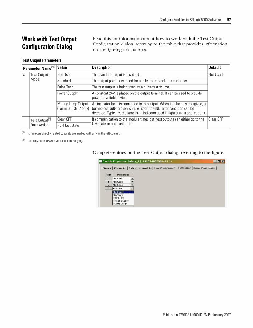
Work with Test Output Configuration Dialog
Read this for information about how to work with the Test Output Configuration dialog, referring to the table that provides information on configuring test outputs.
Complete entries on the Test Output dialog, referring to the figure.
Test Output Parameters
Parameter Name(1) Value Description Default
x Test Output Mode
Not Used The standard output is disabled. Not UsedStandard The output point is enabled for use by the GuardLogix controller.Pulse Test The test output is being used as a pulse test source.Power Supply A constant 24V is placed on the output terminal. It can be used to provide
power to a field device.Muting Lamp Output (Terminal T3/T7 only)
An indicator lamp is connected to the output. When this lamp is energized, a burned-out bulb, broken wire, or short to GND error condition can be detected. Typically, the lamp is an indicator used in light curtain applications.
Test Output(2) Fault Action
Clear OFF If communication to the module times out, test outputs can either go to the OFF state or hold last state.
Clear OFFHold last state
(1) Parameters directly related to safety are marked with an X in the left column.
(2) Can only be read/write via explicit messaging.
Publication 1791DS-UM001D-EN-P - January 2007

58 Configure Modules in RSLogix 5000 Software
Work with the Output Configuration Dialog
Read this for a procedure on how to configure safety outputs by using the information in the table and completing the entries referring to the figure.
Safety Output Parameters
Parameter Name(1)
Value Description Default
x Point Operation Type
Single The output is treated as a single channel. Dual-channelDual The 1791DS module treats the outputs as a pair. It always sets them HI to LO as a
matched pair. Safety logic must set both of these outputs ON or OFF at the same time or the module will declare a channel fault.
x Point Mode Not Used The output is disabled. Not UsedSafety The output point is enabled, and it does not perform a pulse test on the output.Safety Pulse Test The output point is enabled and performs a pulse test on the output.
When the output is energized, the output pulses LO briefly. The pulse test detects if 24V remains on the output terminal during this LO pulse due to a short to 24V or if the output is shorted to another output terminal.
x Output Error Latch Time
0…65,530 ms (in increments of 10 ms)
The purpose for latching output errors is to make sure that intermittent faults that may only exist for a few milliseconds are latched long enough to be read by the controller. The amount of time to latch the errors will be based on the RPI, the safety task watchdog, and other application-specific variables.
1000 ms
(1) Parameters directly related to safety are marked with an X in the left column.
Publication 1791DS-UM001D-EN-P - January 2007
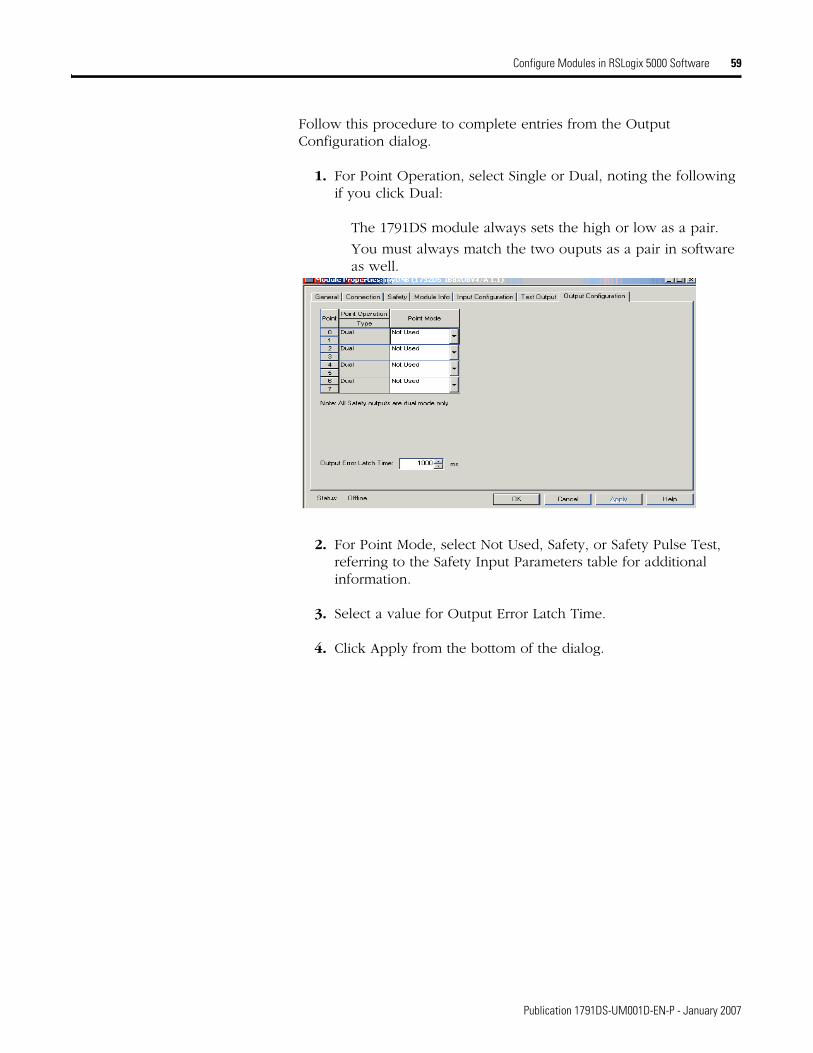
Configure Modules in RSLogix 5000 Software 59
Follow this procedure to complete entries from the Output Configuration dialog.
1. For Point Operation, select Single or Dual, noting the following if you click Dual:
The 1791DS module always sets the high or low as a pair.
You must always match the two ouputs as a pair in software as well.
2. For Point Mode, select Not Used, Safety, or Safety Pulse Test, referring to the Safety Input Parameters table for additional information.
3. Select a value for Output Error Latch Time.
4. Click Apply from the bottom of the dialog.
Publication 1791DS-UM001D-EN-P - January 2007
60 Configure Modules in RSLogix 5000 Software
Save Module Configuration We recommend that after a module is configured you save your work.
After downloading the program, if the MS and NS LED indicators on the 1791DS module are not both solid green, this may be due to loss of ownership. The ownership is based on the following:
1791DS DeviceNet node number
1791DS safety network number
GuardLogix slot number
GuardLogix safety network number
If any of these change, the connection between the GuardLogix module and the 1791DS module is lost, and the yellow yield in the RSLogix 5000 tree appears. Reset ownership to reestablish the connection using this procedure.
1. From within RSLogix 5000 software, open the safety I/O module properties.
2. Click the Safety tab.
3. From the dialog, click Reset ownership.
Status Data Supported by Each Module
See Appendix D, Configuration Reference Information, for the tables that show the I/O data supported by each module. Refer to I/O Assembly Data for data arrangements.
For I/O data, safety connections for up to four items, including one output, can be allocated for the master unit, and standard connections for up to two items can be allocated for the master unit (scanner).
Publication 1791DS-UM001D-EN-P - January 2007

Chapter 5
Configure Modules in RSNetWorx for DeviceNet Software
What This Chapter Contains This chapter provides information about how to configure Guard I/O modules by using RSNetWorx for DeviceNet software and a SmartGuard controller. Refer to the corresponding software help files for network-configurator operating procedures.
This chapter covers how to configure a SmartGuard controller and Guard I/O module by using Universal Serial Bus (USB) connectivity. For related information, see the appendix that contains sample SmartGuard application code.
Configure a SmartGuard Controller
Use this procedure to configure a SmartGuard controller and Guard I/O module by using Universal Serial Bus (USB) connectivity.
1. Be sure you have these required items:
RSNetWorx for DeviceNet software, version 8.0 or later
RSLinx software, version 2.51 or later
SmartGuard USB driver
Personal computer with Microsoft Windows 2000, Microsoft Windows 2000 Terminal Server, or Microsoft Windows XP
2. Load the SmartGuard USB driver onto your computer, noting the folder location, as you need to browse to it later.
61 Publication 1791DS-UM001E-EN-P - January 2007
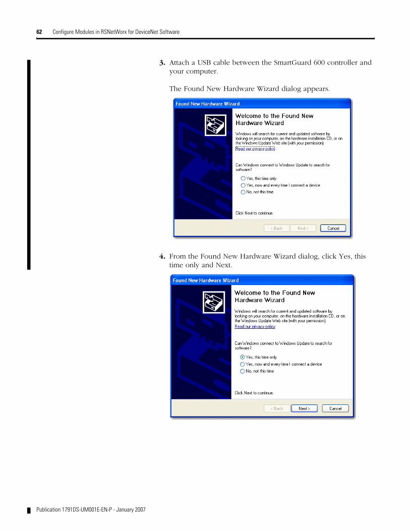
62 Configure Modules in RSNetWorx for DeviceNet Software
3. Attach a USB cable between the SmartGuard 600 controller and your computer.
The Found New Hardware Wizard dialog appears.
4. From the Found New Hardware Wizard dialog, click Yes, this time only and Next.
Publication 1791DS-UM001E-EN-P - January 2007

Configure Modules in RSNetWorx for DeviceNet Software 63
5. From the Found New Hardware Wizard dialog that appears, click Install from a list or specific location (Advanced) and Next.
6. From the Found New Hardware Wizard dialog that appears, click Browse.
Publication 1791DS-UM001E-EN-P - January 2007
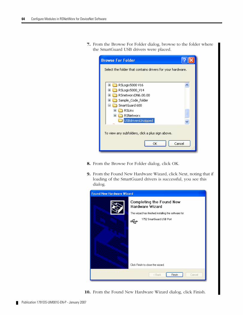
64 Configure Modules in RSNetWorx for DeviceNet Software
Publication 1791DS-UM001E-EN-P - January 2007
7. From the Browse For Folder dialog, browse to the folder where the SmartGuard USB drivers were placed.
8. From the Browse For Folder dialog, click OK.
9. From the Found New Hardware Wizard, click Next, noting that if loading of the SmartGuard drivers is successful, you see this dialog.
10. From the Found New Hardware Wizard dialog, click Finish.
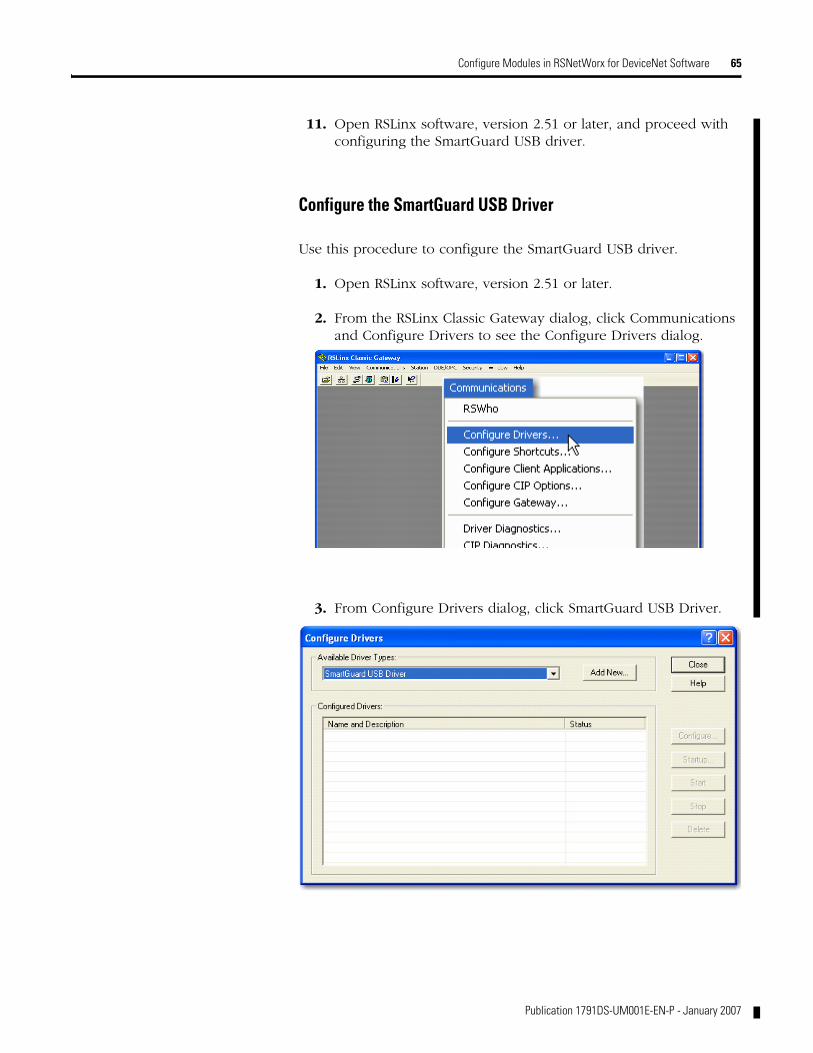
Configure Modules in RSNetWorx for DeviceNet Software 65
11. Open RSLinx software, version 2.51 or later, and proceed with configuring the SmartGuard USB driver.
Configure the SmartGuard USB Driver
Use this procedure to configure the SmartGuard USB driver.
1. Open RSLinx software, version 2.51 or later.
2. From the RSLinx Classic Gateway dialog, click Communications and Configure Drivers to see the Configure Drivers dialog.
3. From Configure Drivers dialog, click SmartGuard USB Driver.
Publication 1791DS-UM001E-EN-P - January 2007
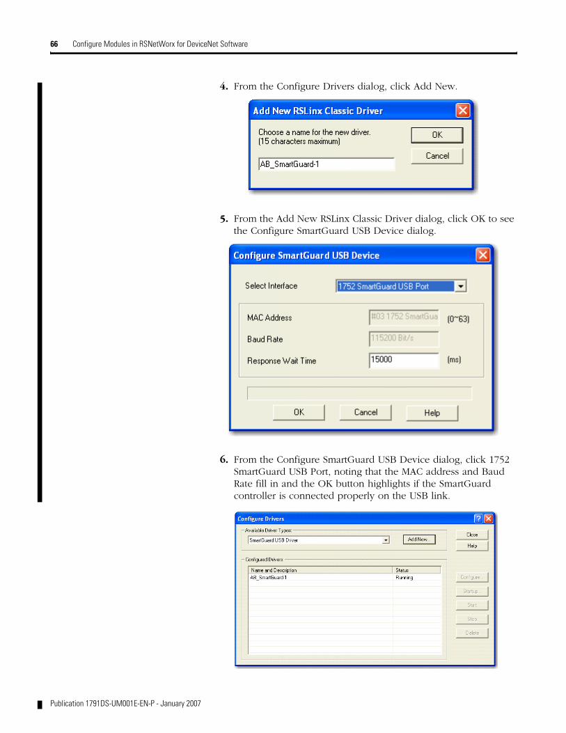
66 Configure Modules in RSNetWorx for DeviceNet Software
4. From the Configure Drivers dialog, click Add New.
5. From the Add New RSLinx Classic Driver dialog, click OK to see the Configure SmartGuard USB Device dialog.
6. From the Configure SmartGuard USB Device dialog, click 1752 SmartGuard USB Port, noting that the MAC address and Baud Rate fill in and the OK button highlights if the SmartGuard controller is connected properly on the USB link.
Publication 1791DS-UM001E-EN-P - January 2007

Configure Modules in RSNetWorx for DeviceNet Software 67
7. From the Configure SmartGuard USB Device dialog, click OK to see the Configure Drivers dialog, noting that the SmartGuard driver should be running.
8. From the Configure Drivers dialog, click close.
9. Follow the procedure for working with RSNetworx for DeviceNet software.
Work with RSNetworx for DeviceNet Software
Use this procedure to work with RSNetworx for DeviceNet software.
1. Before you begin to design a project with RSNetworx for DeviceNet software, follow these procedures.
a. Load the proper electronic data sheet (EDS) files using the EDS Hardware Installation Tool. For all products, as needed, for your project, if using the following for the first time, find the EDS files at http://www.rockwellautomation.com/:
1791DS Guard I/O modules
1732DS Guard I/O modules
1752 SmartGuard controller
b. From RSLinx software, open RSWho and select the SmartGuard driver, noting that it browses the DeviceNet network connected to the SmartGuard.
Publication 1791DS-UM001E-EN-P - January 2007

68 Configure Modules in RSNetWorx for DeviceNet Software
In this case, we have a single 1791DS safety I/O module connected to the SmartGuard.
Note that images of the 1791DS module and SmartGuard (1752) controller show up when you previously load the proper EDS files using the EDS Hardware Installation Tool.
Note that if RSLinx software sees the nodes on the DeviceNet network, RSNetworx sees the nodes.
Publication 1791DS-UM001E-EN-P - January 2007

Configure Modules in RSNetWorx for DeviceNet Software 69
2. Open RSNetworx for DeviceNet software, create a new project, and click the Online icon to see the Browse for network dialog.
3. From the Browse for network dialog, click the SmartGuard driver and OK.
4. In RSNetworx for DeviceNet software, if you have created a new project, this RSNetWorx for DeviceNet dialog appears.
Publication 1791DS-UM001E-EN-P - January 2007
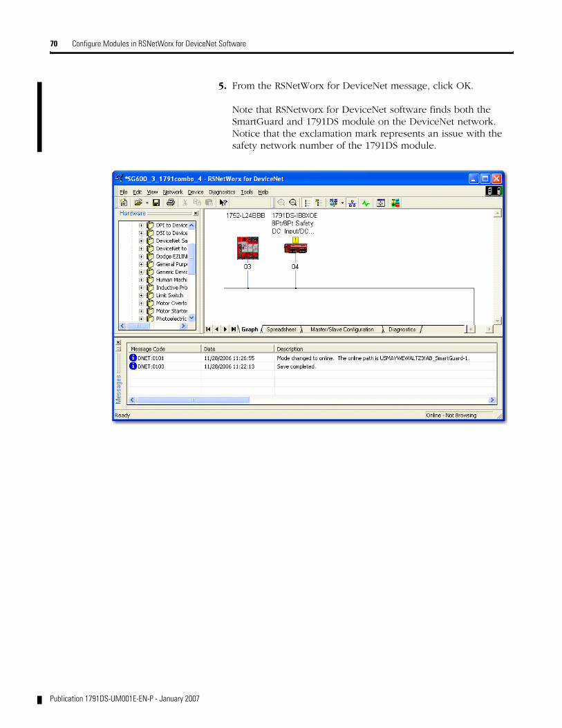
70 Configure Modules in RSNetWorx for DeviceNet Software
5. From the RSNetWorx for DeviceNet message, click OK.
Note that RSNetworx for DeviceNet software finds both the SmartGuard and 1791DS module on the DeviceNet network. Notice that the exclamation mark represents an issue with the safety network number of the 1791DS module.
Publication 1791DS-UM001E-EN-P - January 2007
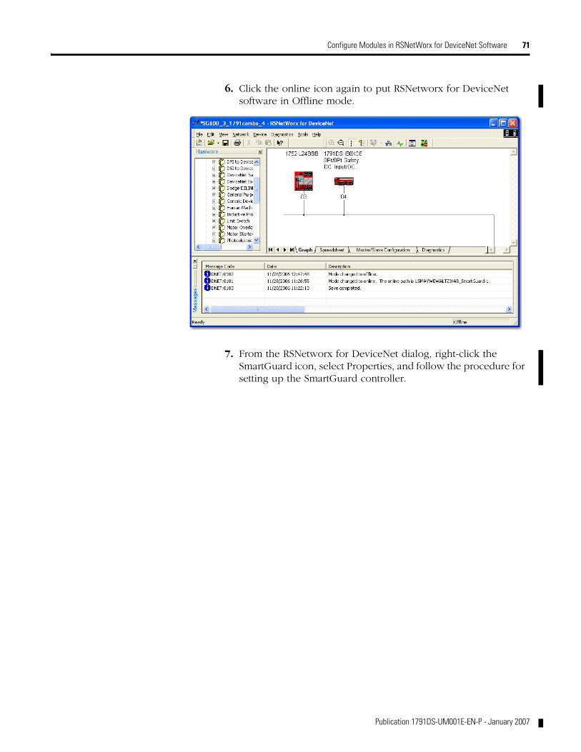
Configure Modules in RSNetWorx for DeviceNet Software 71
6. Click the online icon again to put RSNetworx for DeviceNet software in Offline mode.
7. From the RSNetworx for DeviceNet dialog, right-click the SmartGuard icon, select Properties, and follow the procedure for setting up the SmartGuard controller.
Publication 1791DS-UM001E-EN-P - January 2007
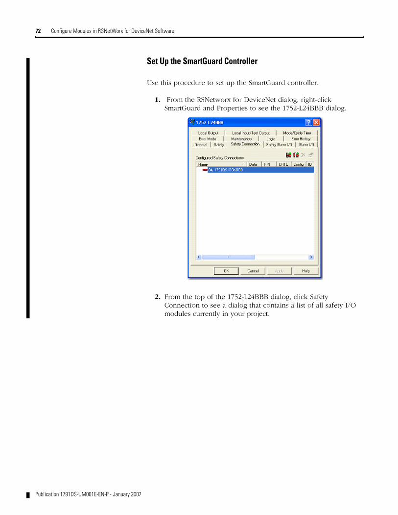
72 Configure Modules in RSNetWorx for DeviceNet Software
Set Up the SmartGuard Controller
Use this procedure to set up the SmartGuard controller.
1. From the RSNetworx for DeviceNet dialog, right-click SmartGuard and Properties to see the 1752-L24BBB dialog.
2. From the top of the 1752-L24BBB dialog, click Safety Connection to see a dialog that contains a list of all safety I/O modules currently in your project.
Publication 1791DS-UM001E-EN-P - January 2007
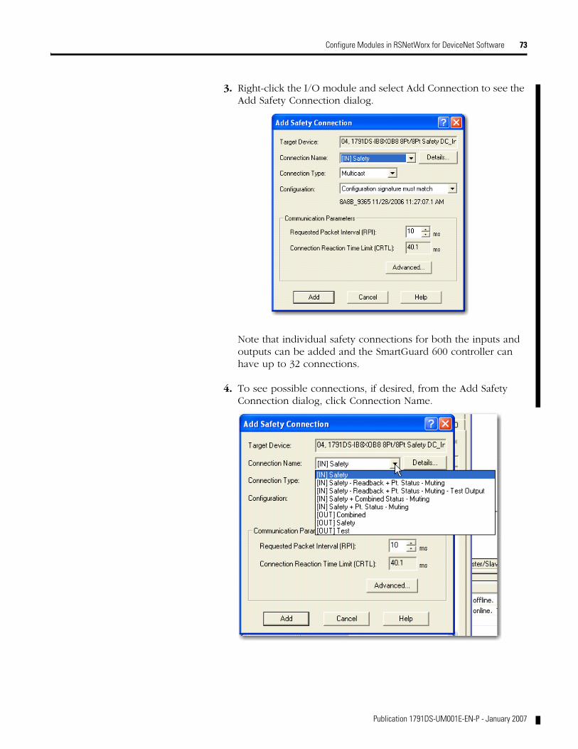
Configure Modules in RSNetWorx for DeviceNet Software 73
3. Right-click the I/O module and select Add Connection to see the Add Safety Connection dialog.
Note that individual safety connections for both the inputs and outputs can be added and the SmartGuard 600 controller can have up to 32 connections.
4. To see possible connections, if desired, from the Add Safety Connection dialog, click Connection Name.
Publication 1791DS-UM001E-EN-P - January 2007

74 Configure Modules in RSNetWorx for DeviceNet Software
Note these input and output connection options:
Input connection options
Readback is status of 24V on the output terminals.
Pt (point) status provides individual status for each input and output point.
Combined status is one bit for all inputs, one bit for all safety outputs.
Muting status and Test Output status are available.
The more status read, the larger the packet size.
Output connection options
Safety provides control of safety outputs, but not test outputs.
Test provides control of test outputs, but not safety outputs.
Combined provides control of both safety and test outputs.
5. From the Add Safety Connection dialog, make selections as shown in the following dialog and click Add, noting that a typical selection is combined status for the input connection.
This limits the packet size for normal communications. If detailed status is required when a fault occurs, that data can be read explicitly via MSG instructions.
6. Right-click the I/O module and select Add Connection.
Publication 1791DS-UM001E-EN-P - January 2007
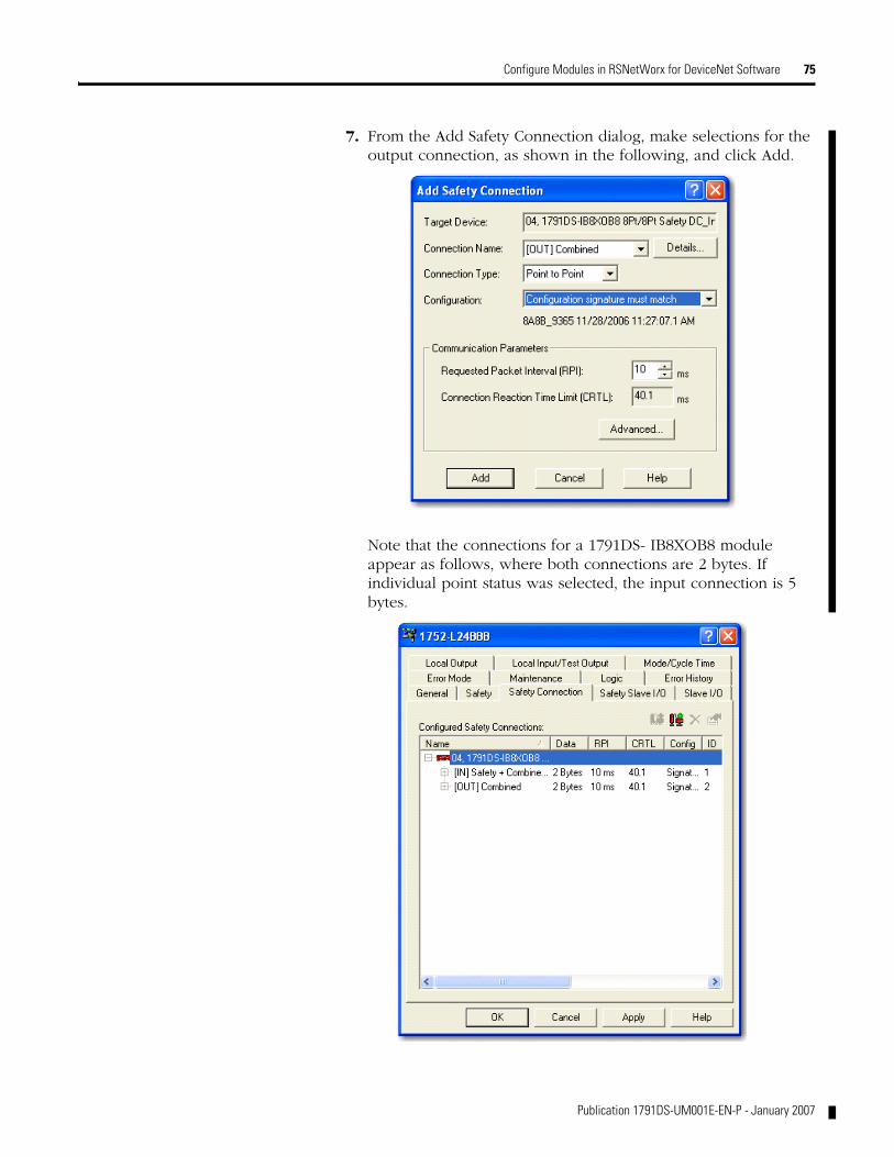
Configure Modules in RSNetWorx for DeviceNet Software 75
7. From the Add Safety Connection dialog, make selections for the output connection, as shown in the following, and click Add.
Note that the connections for a 1791DS- IB8XOB8 module appear as follows, where both connections are 2 bytes. If individual point status was selected, the input connection is 5 bytes.
Publication 1791DS-UM001E-EN-P - January 2007
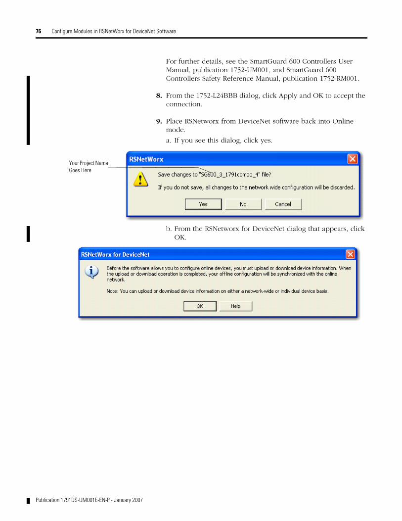
76 Configure Modules in RSNetWorx for DeviceNet Software
For further details, see the SmartGuard 600 Controllers User Manual, publication 1752-UM001, and SmartGuard 600 Controllers Safety Reference Manual, publication 1752-RM001.
8. From the 1752-L24BBB dialog, click Apply and OK to accept the connection.
9. Place RSNetworx from DeviceNet software back into Online mode.
a. If you see this dialog, click yes.
b. From the RSNetworx for DeviceNet dialog that appears, click OK.
Your Project Name Goes Here
Publication 1791DS-UM001E-EN-P - January 2007

Configure Modules in RSNetWorx for DeviceNet Software 77
You see the following nodes after the browse.
10. Right-click the SmartGuard 600 controller, select Download to Device, and follow the download procedure.
Publication 1791DS-UM001E-EN-P - January 2007
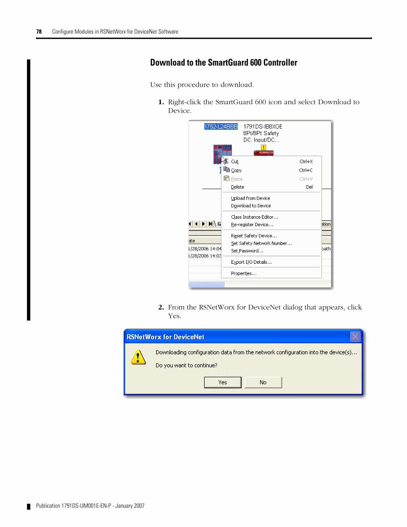
78 Configure Modules in RSNetWorx for DeviceNet Software
Download to the SmartGuard 600 Controller
Use this procedure to download.
1. Right-click the SmartGuard 600 icon and select Download to Device.
2. From the RSNetWorx for DeviceNet dialog that appears, click Yes.
Publication 1791DS-UM001E-EN-P - January 2007

Configure Modules in RSNetWorx for DeviceNet Software 79
Notice that this dialog appears during the download to the SmartGuard 600.
If the download is successful, text appears in the message area, as shown in the following dialog.
Publication 1791DS-UM001E-EN-P - January 2007
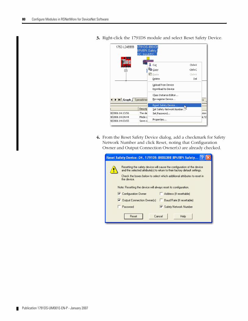
80 Configure Modules in RSNetWorx for DeviceNet Software
3. Right-click the 1791DS module and select Reset Safety Device.
4. From the Reset Safety Device dialog, add a checkmark for Safety Network Number and click Reset, noting that Configuration Owner and Output Connection Owner(s) are already checked.
Publication 1791DS-UM001E-EN-P - January 2007
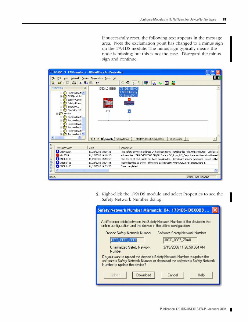
Configure Modules in RSNetWorx for DeviceNet Software 81
If successfully reset, the following text appears in the message area. Note the exclamation point has changed to a minus sign on the 1791DS module. The minus sign typically means the node is missing; but this is not the case. Disregard the minus sign and continue.
5. Right-click the 1791DS module and select Properties to see the Safety Network Number dialog.
Publication 1791DS-UM001E-EN-P - January 2007

82 Configure Modules in RSNetWorx for DeviceNet Software
6. From the Safety Network Number dialog, click Download to download the safety network number from the offline project to the 1791DS module.
7. Verify that the NS LED indicator on the 1791DS module is flashing red/green and from the Confirm Safety Network Number dialog, click OK.
8. If the SNN is set, the RSNetworx for DeviceNet dialog appears.
Publication 1791DS-UM001E-EN-P - January 2007
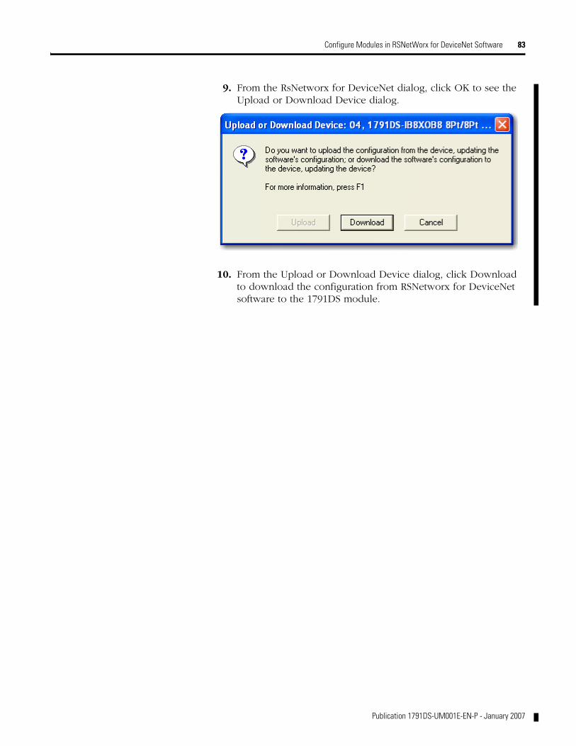
Configure Modules in RSNetWorx for DeviceNet Software 83
9. From the RsNetworx for DeviceNet dialog, click OK to see the Upload or Download Device dialog.
10. From the Upload or Download Device dialog, click Download to download the configuration from RSNetworx for DeviceNet software to the 1791DS module.
Publication 1791DS-UM001E-EN-P - January 2007
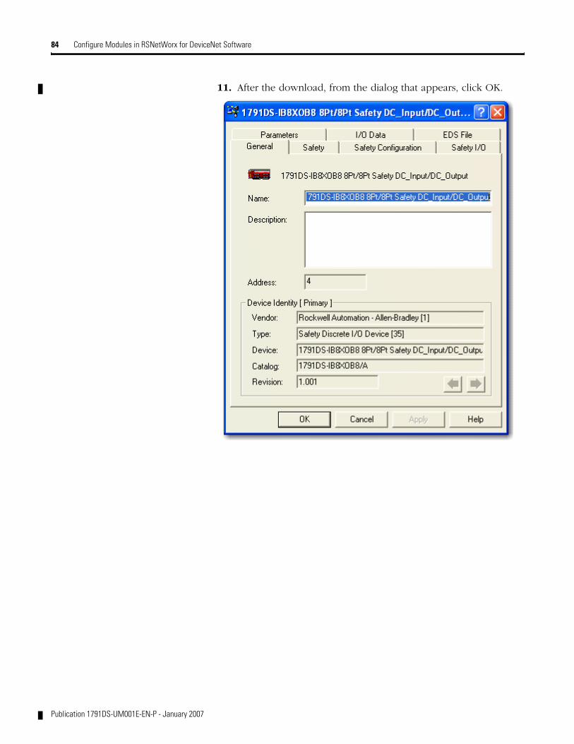
84 Configure Modules in RSNetWorx for DeviceNet Software
11. After the download, from the dialog that appears, click OK.
Publication 1791DS-UM001E-EN-P - January 2007

Chapter 6
Wiring Examples
What This Chapter Contains Read this chapter for information about wiring and safety categories. See the tables that show input device connection methods and their safety categories.
Connected Device and Safety Category
Connected Device
Test Output Configured For Pulse Test
Connection Schematic Diagram Safety Category
Reset switch No Connect the switch between IN0 and T0, noting that T0 is configured for 24V power supply. .
-
Connect the switch between 24V dc and IN0.
-
44098
IN0 T0 IN1 T1
IN0 T0 IN1 T1
44100
24V
85 Publication 1791DS-UM001E-EN-P - January 2007

86 Wiring Examples
Emergency stop switch
Door monitor
Yes Connect the switches between IN0 and T0, andIN1 and T1.
4
No Connect the switches between T0 and IN0, IN1, noting that T0 is configured for 24V power supply.
3
Connect the switches between 24V dc and IN0, IN1.
Light curtain No Connect the OSSD1 and OSSD2 to IN0 and IN1, respectively.
4
Connected Device and Safety Category
Connected Device
Test Output Configured For Pulse Test
Connection Schematic Diagram Safety Category
44101
IN0 T0 IN1 T1
IN0 T0 IN1 T1
44102
IN0 T0 IN1 T1
44135
24V
OSSD2
OSSD1
OSSD1
OSSD2
IN0 T0 IN1 T1
44103
Publication 1791DS-UM001E-EN-P - January 2007

Wiring Examples 87
Examples of Wiring Read this section for examples of wiring by application.
1791DS-IB12 Emergency Stop Switch Dual-channel Inputs with Manual Reset
G T0 T1
V INO IN1
T1 G
IN11
T2
E1
S1S2
11 21
12 22
E1: 24V dc Power Supply
S1: Emergency Stop Switch (Positive Opening Mechanism)
S2: Reset Switch
44104
1791DS-IB12 Emergency Stop Switch Dual-channel Inputs with Manual Reset
Controller Configuration Parameter Name ValueSafety Input 0 Safety Input 0 Channel Mode Test Pulse from Test Output
Safety Input 0 Test Source Test Output 0 Dual-channel Safety Input 0/1 Mode Dual-channel EquivalentDual-channel Safety Input 0/1 Discrepancy Time 100 x 10 ms (application dependent)
Safety Input 1 Safety Input 1 Channel Mode Test Pulse from Test OutputSafety Input 1 Test Source Test Output 1
Safety Input 11 Safety Input 11 Channel Mode Used as Standard Input Safety Input 11 Test Source Not UsedDual-channel Safety Input 10/11 Mode Single Channel
Test Output 0 Test Output 0 Mode Pulse Test Output Test Output 1 Test Output 1 Mode Pulse Test Output Test Output 2 Test Output 2 Mode Power Supply Output
This example shows wiring and controller configuration when using the 1791DS-IB12 slave.
If used in combination with the programs in a safety controller, this wiring is Safety Category 4 in accordance with EN 954-1 wiring requirements.
Publication 1791DS-UM001E-EN-P - January 2007
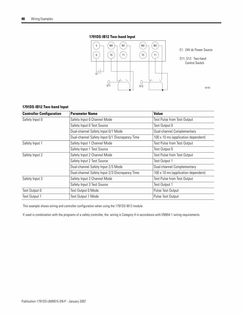
88 Wiring Examples
1791DS-IB12 Two-hand Input
G T0 T1
V INO IN1
E1
S11
T0 T1
IN2 IN3
S12
E1: 24V dc Power Source
S11, S12: Two-hand Control Switch
44105
1791DS-IB12 Two-hand Input
Controller Configuration Parameter Name ValueSafety Input 0 Safety Input 0 Channel Mode Test Pulse from Test Output
Safety Input 0 Test Source Test Output 0 Dual-channel Safety Input 0/1 Mode Dual-channel ComplementaryDual-channel Safety Input 0/1 Discrepancy Time 100 x 10 ms (application dependent)
Safety Input 1 Safety Input 1 Channel Mode Test Pulse from Test OutputSafety Input 1 Test Source Test Output 0
Safety Input 2 Safety Input 2 Channel Mode Test Pulse from Test OutputSafety Input 2 Test Source Test Output 1 Dual-channel Safety Input 2/3 Mode Dual-channel ComplementaryDual-channel Safety Input 2/3 Discrepancy Time 100 x 10 ms (application dependent)
Safety Input 3 Safety Input 3 Channel Mode Test Pulse from Test OutputSafety Input 3 Test Source Test Output 1
Test Output 0 Test Output 0 Mode Pulse Test Output Test Output 1 Test Output 1 Mode Pulse Test Output
This example shows wiring and controller configuration when using the 1791DS-IB12 module.
If used in combination with the programs of a safety controller, the wiring is Category 4 in accordance with EN954-1 wiring requirements.
Publication 1791DS-UM001E-EN-P - January 2007
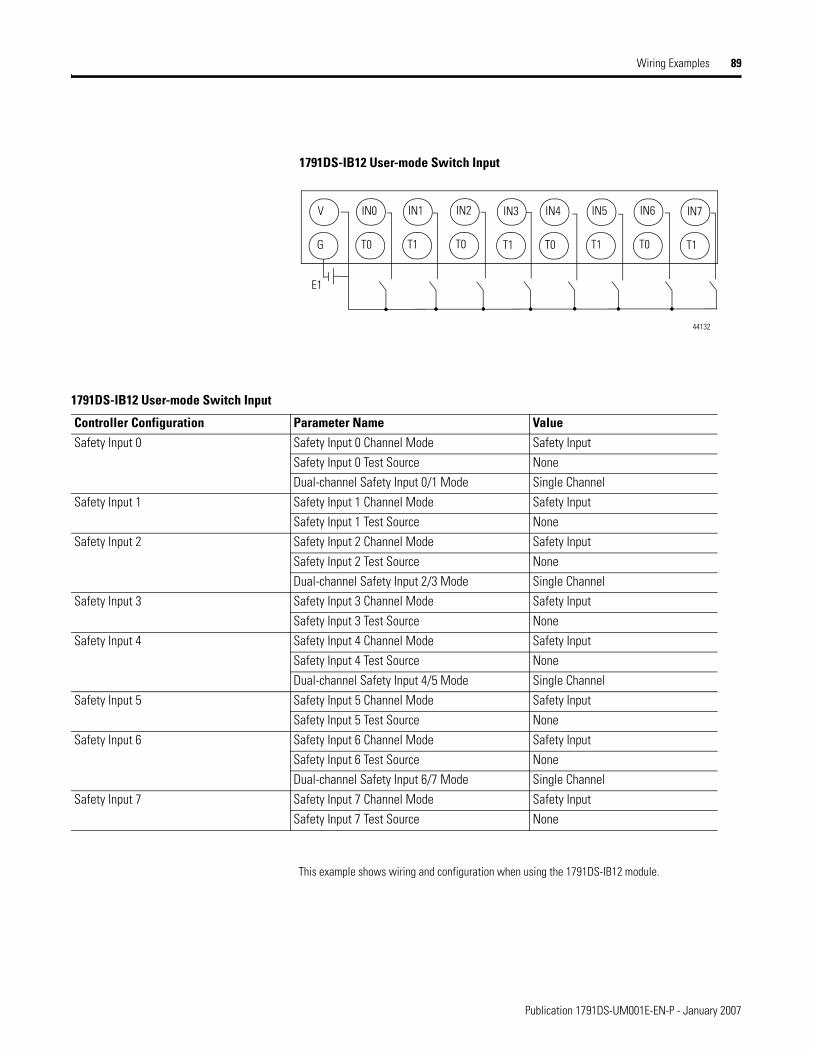
Wiring Examples 89
This example shows wiring and configuration when using the 1791DS-IB12 module.
1791DS-IB12 User-mode Switch Input
44132
T0 T1 T0 T1 T0 T1 T0 T1
IN0 IN1 IN2 IN3 IN4 IN5 IN6 IN7
G
V
E1
1791DS-IB12 User-mode Switch Input
Controller Configuration Parameter Name ValueSafety Input 0 Safety Input 0 Channel Mode Safety Input
Safety Input 0 Test Source NoneDual-channel Safety Input 0/1 Mode Single Channel
Safety Input 1 Safety Input 1 Channel Mode Safety InputSafety Input 1 Test Source None
Safety Input 2 Safety Input 2 Channel Mode Safety InputSafety Input 2 Test Source NoneDual-channel Safety Input 2/3 Mode Single Channel
Safety Input 3 Safety Input 3 Channel Mode Safety InputSafety Input 3 Test Source None
Safety Input 4 Safety Input 4 Channel Mode Safety InputSafety Input 4 Test Source NoneDual-channel Safety Input 4/5 Mode Single Channel
Safety Input 5 Safety Input 5 Channel Mode Safety InputSafety Input 5 Test Source None
Safety Input 6 Safety Input 6 Channel Mode Safety InputSafety Input 6 Test Source NoneDual-channel Safety Input 6/7 Mode Single Channel
Safety Input 7 Safety Input 7 Channel Mode Safety InputSafety Input 7 Test Source None
Publication 1791DS-UM001E-EN-P - January 2007
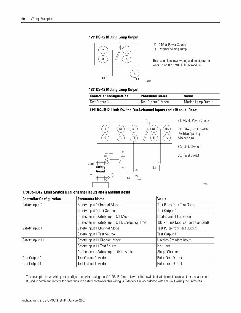
90 Wiring Examples
1791DS-12 Muting Lamp Output
1791DS-IB12 Limit Switch Dual-channel Inputs and a Manual Reset
1791DS-12 Muting Lamp Output
Controller Configuration Parameter Name ValueTest Output 3 Test Output 3 Mode Muting Lamp Output
G G
X
V T3
E1 L1
E1: 24V dc Power Source L1: External Muting Lamp
44107
This example shows wiring and configuration when using the 1791DS-IB 12 module.
1791DS-IB12 Limit Switch Dual-channel Inputs and a Manual Reset
Controller Configuration Parameter Name ValueSafety Input 0 Safety Input 0 Channel Mode Test Pulse from Test Output
Safety Input 0 Test Source Test Output 0 Dual-channel Safety Input 0/1 Mode Dual-channel EquivalentDual-channel Safety Input 0/1 Discrepancy Time 100 x 10 ms (application dependent)
Safety Input 1 Safety Input 1 Channel Mode Test Pulse from Test OutputSafety Input 1 Test Source Test Output 1
Safety Input 11 Safety Input 11 Channel Mode Used as Standard Input Safety Input 11 Test Source Not UsedDual-channel Safety Input 10/11 Mode Single Channel
Test Output 0 Test Output 0 Mode Pulse Test Output Test Output 1 Test Output 1 Mode Pulse Test Output
G T0 T1
V INO IN1
E1
Close
S2
S312
S1
11
23
24
T1 G
IN11 IN12
E1: 24V dc Power Supply
S1: Safety Limit Switch(Positive Opening Mechanism)
S2: Limit Switch
S3: Reset Switch
44133
Safety Guard
This example shows wiring and configuration when using the 1791DS-IB12 module with limit switch dual-channel inputs and a manual reset. If used in combination with the programs in a safety controller, this wiring is Category 4 in accordance with EN954-1 wiring requirements.
Publication 1791DS-UM001E-EN-P - January 2007
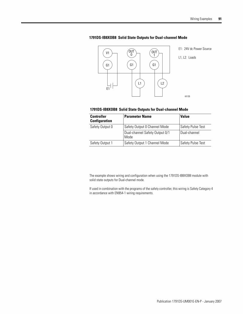
Wiring Examples 91
1791DS-IB8XOB8 Solid State Outputs for Dual-channel Mode
1791DS-IB8XOB8 Solid State Outputs for Dual-channel Mode
Controller Configuration
Parameter Name Value
Safety Output 0 Safety Output 0 Channel Mode Safety Pulse Test Dual-channel Safety Output 0/1 Mode
Dual-channel
Safety Output 1 Safety Output 1 Channel Mode Safety Pulse Test
G1
L1
OUT0
OUT1
E1
G1
L2
G1
V1E1: 24V dc Power Source
L1, L2: Loads
44109
The example shows wiring and configuration when using the 1791DS-IB8XOB8 module with solid state outputs for Dual-channel mode.
If used in combination with the programs of the safety controller, this wiring is Safety Category 4 in accordance with EN954-1 wiring requirements.
Publication 1791DS-UM001E-EN-P - January 2007
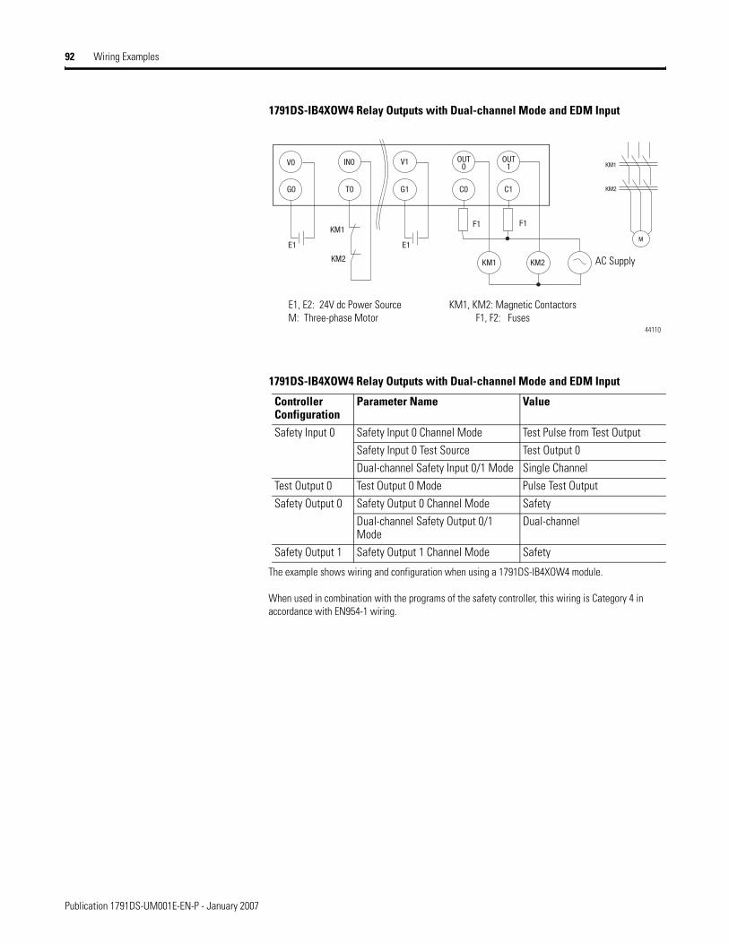
92 Wiring Examples
1791DS-IB4XOW4 Relay Outputs with Dual-channel Mode and EDM Input
1791DS-IB4XOW4 Relay Outputs with Dual-channel Mode and EDM Input
Controller Configuration
Parameter Name Value
Safety Input 0 Safety Input 0 Channel Mode Test Pulse from Test OutputSafety Input 0 Test Source Test Output 0Dual-channel Safety Input 0/1 Mode Single Channel
Test Output 0 Test Output 0 Mode Pulse Test Output Safety Output 0 Safety Output 0 Channel Mode Safety
Dual-channel Safety Output 0/1 Mode
Dual-channel
Safety Output 1 Safety Output 1 Channel Mode Safety
T0
IN0
E1
G1 C0
V1 OUT0
E1
C1
KM1 KM2
OUT1 KM1
KM2
MKM1
KM2
V0
G0
F1 F1
E1, E2: 24V dc Power Source KM1, KM2: Magnetic ContactorsM: Three-phase Motor F1, F2: Fuses
44110
AC Supply
The example shows wiring and configuration when using a 1791DS-IB4XOW4 module.
When used in combination with the programs of the safety controller, this wiring is Category 4 in accordance with EN954-1 wiring.
Publication 1791DS-UM001E-EN-P - January 2007
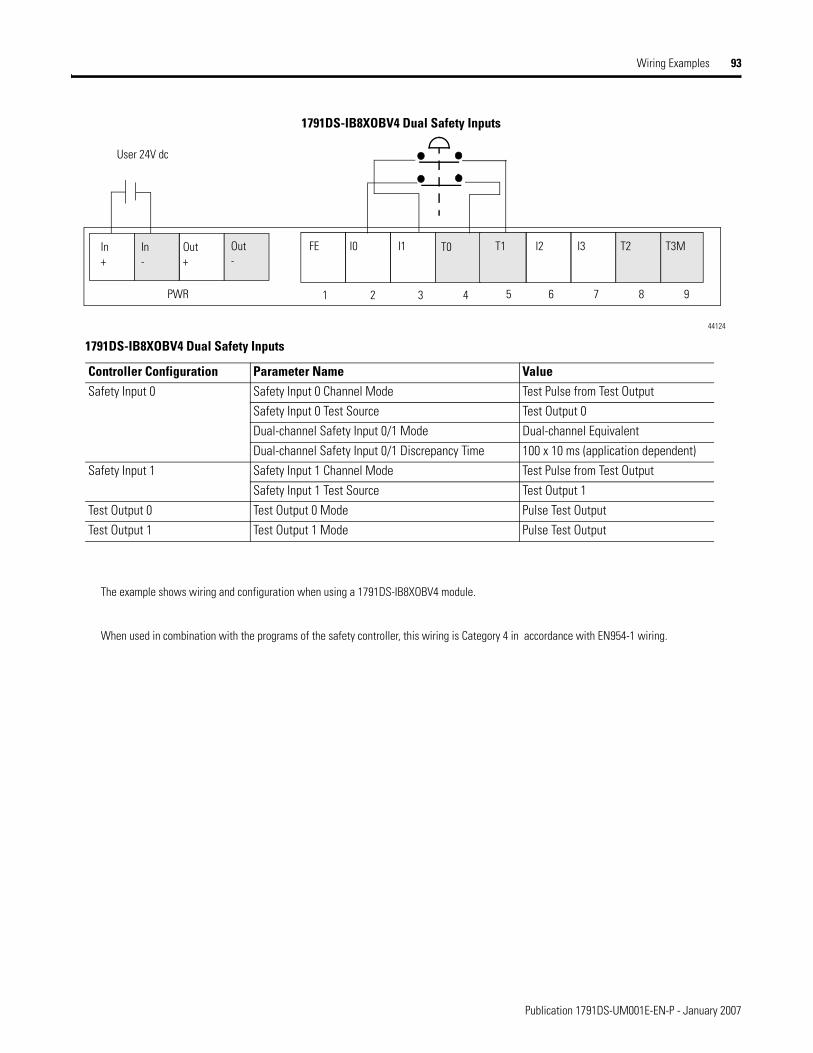
Wiring Examples 93
1791DS-IB8XOBV4 Dual Safety Inputs
User 24V dc
1 2 3 4
In+
In-
44124
PWR 5 6 7 8 9
Out+
Out-
FE I0 I1 T0 T1 I2 I3 T2 T3M
1791DS-IB8XOBV4 Dual Safety Inputs
Controller Configuration Parameter Name ValueSafety Input 0 Safety Input 0 Channel Mode Test Pulse from Test Output
Safety Input 0 Test Source Test Output 0 Dual-channel Safety Input 0/1 Mode Dual-channel EquivalentDual-channel Safety Input 0/1 Discrepancy Time 100 x 10 ms (application dependent)
Safety Input 1 Safety Input 1 Channel Mode Test Pulse from Test OutputSafety Input 1 Test Source Test Output 1
Test Output 0 Test Output 0 Mode Pulse Test Output Test Output 1 Test Output 1 Mode Pulse Test Output
The example shows wiring and configuration when using a 1791DS-IB8XOBV4 module.
When used in combination with the programs of the safety controller, this wiring is Category 4 in accordance with EN954-1 wiring.
Publication 1791DS-UM001E-EN-P - January 2007

94 Wiring Examples
1791DS-IB8XOBV4 Standard Inputs and Outputs
44125
User 24V dc
1 2 3 4 PWR 5 6 7 8 9
FE I0 I1 T0 T1 I2 I3 T2 T3MIn+
In-
Out+
Out-
1791DS-IB8XOBV4 Standard Inputs and Outputs
Controller Configuration Parameter Name ValueInput 0 Safety Input 0 Channel Mode Standard InputTest Pulse 0 Test Output 0 Mode 1 Standard Output
The example shows wiring and configuration when using a 1791DS-IB8XOBV4 module.
Publication 1791DS-UM001E-EN-P - January 2007
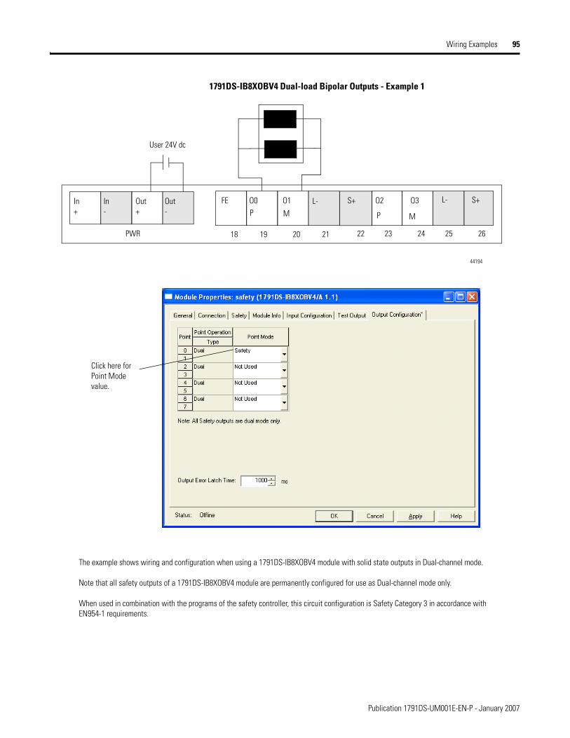
Wiring Examples 95
1791DS-IB8XOBV4 Dual-load Bipolar Outputs - Example 1
18 19 20 21 PWR 22 23 24 25 26
FE O0 O1 L- S+ O2 O3 S+L-In+
In-
Out+
Out-
44194
User 24V dc
The example shows wiring and configuration when using a 1791DS-IB8XOBV4 module with solid state outputs in Dual-channel mode.
Note that all safety outputs of a 1791DS-IB8XOBV4 module are permanently configured for use as Dual-channel mode only.
When used in combination with the programs of the safety controller, this circuit configuration is Safety Category 3 in accordance with EN954-1 requirements.
Click here for Point Mode value.
P PM M
Publication 1791DS-UM001E-EN-P - January 2007
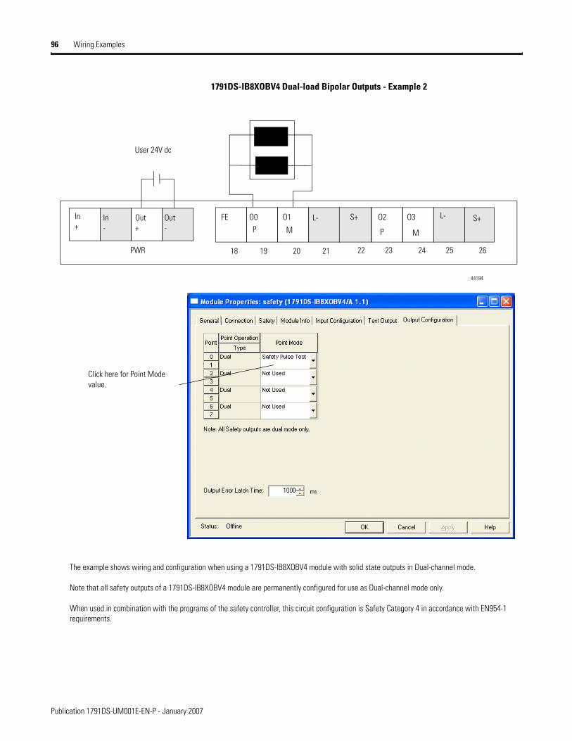
96 Wiring Examples
1791DS-IB8XOBV4 Dual-load Bipolar Outputs - Example 2
18 19 20 21 PWR 22 23 24 25 26
FE O0 O1 L- S+ O2 O3 S+L-In+
In-
Out+
Out-
44194
User 24V dc
The example shows wiring and configuration when using a 1791DS-IB8XOBV4 module with solid state outputs in Dual-channel mode.
Note that all safety outputs of a 1791DS-IB8XOBV4 module are permanently configured for use as Dual-channel mode only.
When used in combination with the programs of the safety controller, this circuit configuration is Safety Category 4 in accordance with EN954-1 requirements.
Click here for Point Mode value.
P PM M
Publication 1791DS-UM001E-EN-P - January 2007

Chapter 7
Interpret the LED Indicators
What This Chapter Contains This chapter includes an explanation of the meaning of module indicators.
1791DS-IB12, 1791DS-IB8XOB8, 1791DS-IB4XOW4 Module LED Indicators
See this section for information on how to interpret these module indicators.
• MS/NS indicators - The MS (module status) indicator displays the status of a node on the network. The NS (network status) indicator displays the status of the entire network. The MS and NS indicators can be green or red and on, flashing, or off.
See the table for meanings indicated by the combination of colors and status.
• LOCK indicator - The configuration lock indicator displays that the configuration data has been locked by using RSNetWorx for DeviceNet software.
• IN PWR/OUT PWR indicators - The IN PWR and OUT PWR indicators displays the status of I/O power supplied to the module.
• I/O indicators - The I/O indicators display how the on/off and fault status of I/O points on each module.
97 Publication 1791DS-UM001E-EN-P - January 2007
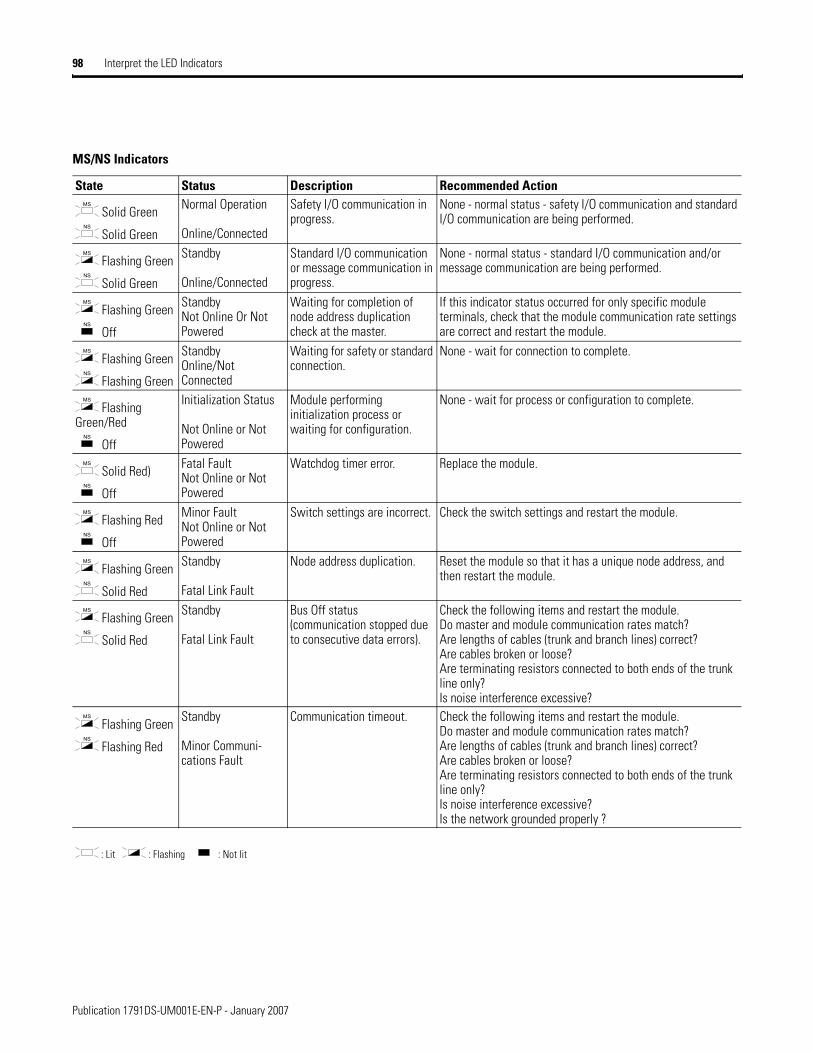
98 Interpret the LED Indicators
MS/NS Indicators
State Status Description Recommended Action
Solid Green
Solid Green
Normal Operation
Online/Connected
Safety I/O communication in progress.
None - normal status - safety I/O communication and standard I/O communication are being performed.
Flashing Green
Solid Green
Standby
Online/Connected
Standard I/O communication or message communication in progress.
None - normal status - standard I/O communication and/or message communication are being performed.
Flashing Green
Off
StandbyNot Online Or Not Powered
Waiting for completion of node address duplication check at the master.
If this indicator status occurred for only specific module terminals, check that the module communication rate settings are correct and restart the module.
Flashing Green
Flashing Green
StandbyOnline/Not Connected
Waiting for safety or standard connection.
None - wait for connection to complete.
Flashing Green/Red
Off
Initialization Status
Not Online or Not Powered
Module performing initialization process or waiting for configuration.
None - wait for process or configuration to complete.
Solid Red)
Off
Fatal FaultNot Online or Not Powered
Watchdog timer error. Replace the module.
Flashing Red
Off
Minor FaultNot Online or Not Powered
Switch settings are incorrect. Check the switch settings and restart the module.
Flashing Green
Solid Red
Standby
Fatal Link Fault
Node address duplication. Reset the module so that it has a unique node address, and then restart the module.
Flashing Green
Solid Red
Standby
Fatal Link Fault
Bus Off status (communication stopped due to consecutive data errors).
Check the following items and restart the module.Do master and module communication rates match?Are lengths of cables (trunk and branch lines) correct?Are cables broken or loose?Are terminating resistors connected to both ends of the trunk line only?Is noise interference excessive?
Flashing Green
Flashing Red
Standby
Minor Communi-cations Fault
Communication timeout. Check the following items and restart the module.Do master and module communication rates match?Are lengths of cables (trunk and branch lines) correct?Are cables broken or loose?Are terminating resistors connected to both ends of the trunk line only?Is noise interference excessive?Is the network grounded properly ?
: Lit : Flashing : Not lit
MS
NS
MS
NS
MS
NS
MS
NS
MS
NS
MS
NS
MS
NS
MS
NS
MS
NS
MS
NS
Publication 1791DS-UM001E-EN-P - January 2007
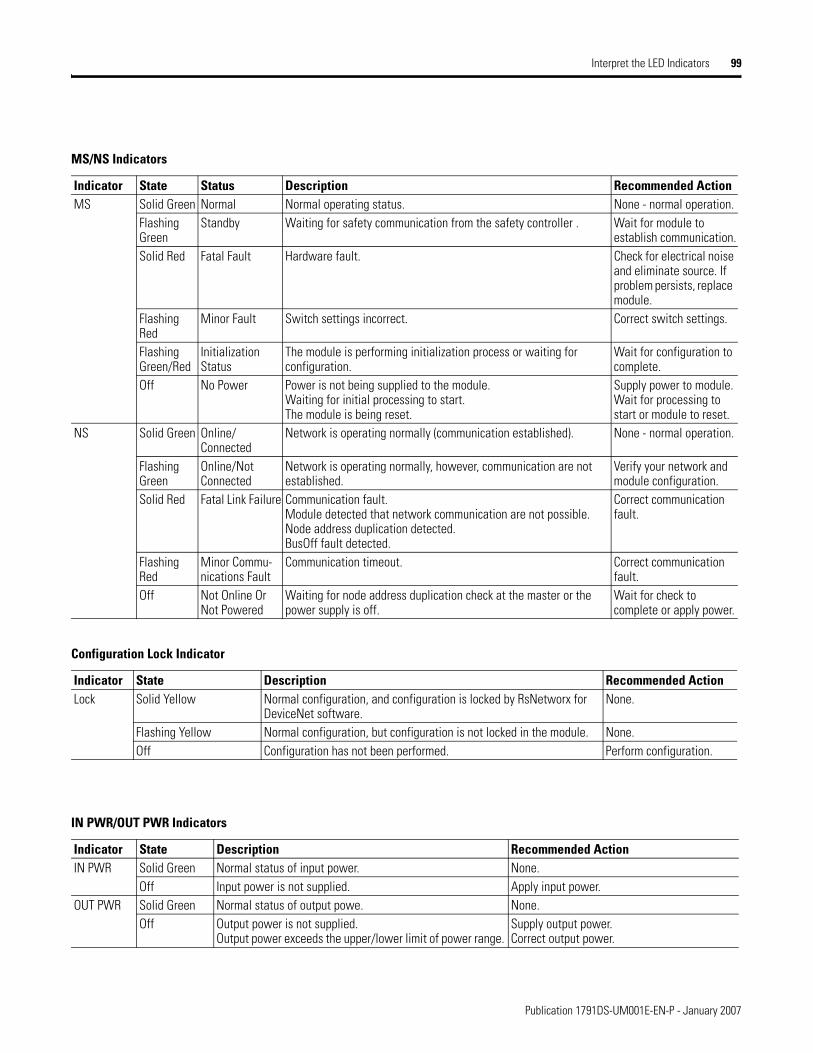
Interpret the LED Indicators 99
MS/NS Indicators
Indicator State Status Description Recommended ActionMS Solid Green Normal Normal operating status. None - normal operation.
Flashing Green
Standby Waiting for safety communication from the safety controller . Wait for module to establish communication.
Solid Red Fatal Fault Hardware fault. Check for electrical noise and eliminate source. If problem persists, replace module.
Flashing Red
Minor Fault Switch settings incorrect. Correct switch settings.
Flashing Green/Red
Initialization Status
The module is performing initialization process or waiting for configuration.
Wait for configuration to complete.
Off No Power Power is not being supplied to the module.Waiting for initial processing to start.The module is being reset.
Supply power to module.Wait for processing to start or module to reset.
NS Solid Green Online/Connected
Network is operating normally (communication established). None - normal operation.
Flashing Green
Online/Not Connected
Network is operating normally, however, communication are not established.
Verify your network and module configuration.
Solid Red Fatal Link Failure Communication fault. Module detected that network communication are not possible.Node address duplication detected.BusOff fault detected.
Correct communication fault.
Flashing Red
Minor Commu-nications Fault
Communication timeout. Correct communication fault.
Off Not Online Or Not Powered
Waiting for node address duplication check at the master or the power supply is off.
Wait for check to complete or apply power.
Configuration Lock Indicator
Indicator State Description Recommended ActionLock Solid Yellow Normal configuration, and configuration is locked by RsNetworx for
DeviceNet software.None.
Flashing Yellow Normal configuration, but configuration is not locked in the module. None.Off Configuration has not been performed. Perform configuration.
IN PWR/OUT PWR Indicators
Indicator State Description Recommended ActionIN PWR Solid Green Normal status of input power. None.
Off Input power is not supplied. Apply input power. OUT PWR Solid Green Normal status of output powe. None.
Off Output power is not supplied. Output power exceeds the upper/lower limit of power range.
Supply output power. Correct output power.
Publication 1791DS-UM001E-EN-P - January 2007
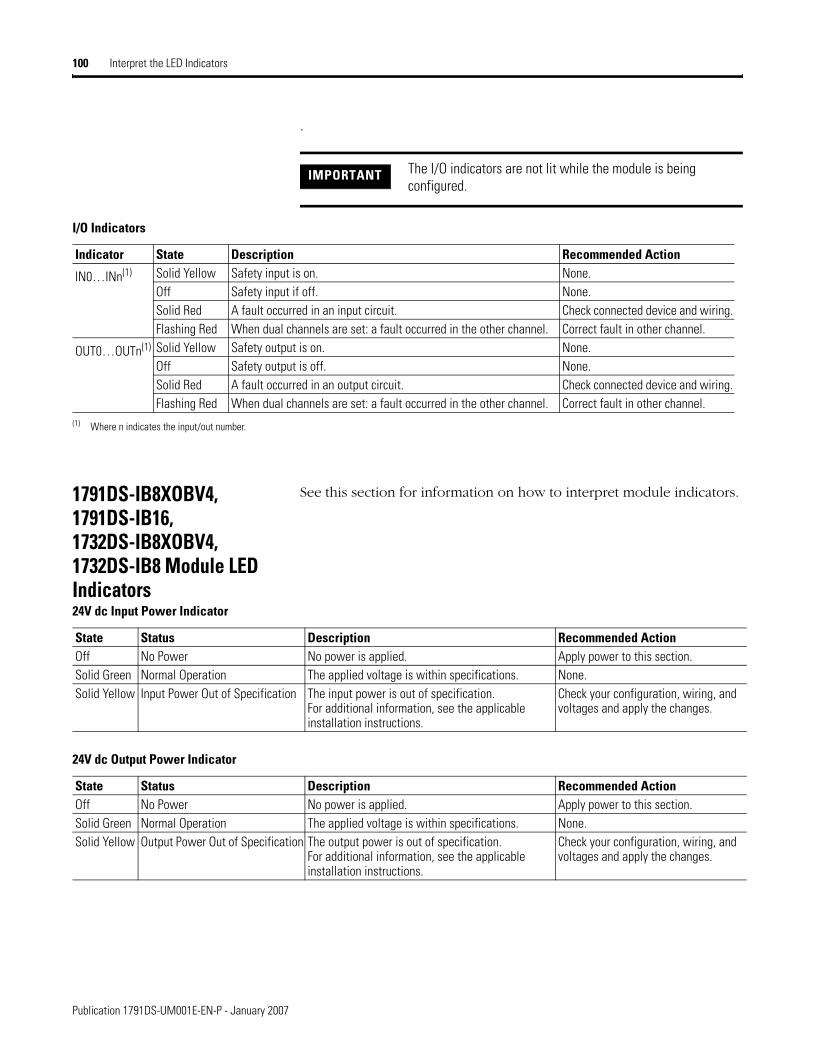
100 Interpret the LED Indicators
.
1791DS-IB8XOBV4, 1791DS-IB16, 1732DS-IB8XOBV4, 1732DS-IB8 Module LED Indicators
See this section for information on how to interpret module indicators.
IMPORTANT The I/O indicators are not lit while the module is being configured.
I/O Indicators
Indicator State Description Recommended Action
IN0…INn(1) Solid Yellow Safety input is on. None.Off Safety input if off. None.Solid Red A fault occurred in an input circuit. Check connected device and wiring.Flashing Red When dual channels are set: a fault occurred in the other channel. Correct fault in other channel.
OUT0…OUTn(1) Solid Yellow Safety output is on. None.Off Safety output is off. None.Solid Red A fault occurred in an output circuit. Check connected device and wiring.Flashing Red When dual channels are set: a fault occurred in the other channel. Correct fault in other channel.
(1) Where n indicates the input/out number.
24V dc Input Power Indicator
State Status Description Recommended ActionOff No Power No power is applied. Apply power to this section.Solid Green Normal Operation The applied voltage is within specifications. None.Solid Yellow Input Power Out of Specification The input power is out of specification.
For additional information, see the applicable installation instructions.
Check your configuration, wiring, and voltages and apply the changes.
24V dc Output Power Indicator
State Status Description Recommended ActionOff No Power No power is applied. Apply power to this section.Solid Green Normal Operation The applied voltage is within specifications. None.Solid Yellow Output Power Out of Specification The output power is out of specification.
For additional information, see the applicable installation instructions.
Check your configuration, wiring, and voltages and apply the changes.
Publication 1791DS-UM001E-EN-P - January 2007

Interpret the LED Indicators 101
Module Status Indicator
State Status Description Recommended ActionOff No Power or Autobauding No power is applied to the DeviceNet connector. Apply power to this connector.Solid Green Normal Operation The module is operating normally. None.Solid Red Unrecoverable Fault The module has detected an unrecoverable fault. Cycle power to the module. If problem
persists, replace the module.Flashing Green
Module Needs Commissioning Due to Missing, Incomplete, or Incorrect Configuration
Module is unconfigured. Reconfigure the module. For additional information, inspect Network Status indicator.
Flashing Red Recoverable Fault or User-initiated Firmware Update
The module has detected a recoverable fault or user-initiated firmware update is in progress.
Cycle power to the module or reset the module.
Flashing Red and Green
Device in Self Test The module is performing its power-cycle diagnostic tests.
Wait for the module to complete its power-cycle diagnostics.
Network Status Indicator
State Status Description Recommended ActionOff Module Not Online or No Power The module is not online with the network. Verify your network.Flashing Green
Module Online With No Connections in Established State
The module identified the communication rate of the network but no connections are established.
Verify your network and module configuration.
Solid Green Module Online with Connections in Established State
The module is operating normally. None.
Flashing Red
One or more I/O Connections in Timed-out State or User-initiated Firmware Update
The module detected a recoverable network fault, or user-initiated firmware update is in progress.
Verify your network and module configuration.
Solid Red Critical Link Failure The module detected an error that prevents it from communicating on the network.
Cycle power to the module, If problem persists, replace the module.
Flashing Red and Green
Communication Faulted Module The module detected a network access error and is in communication faulted state. The module has received and accepted an Identity Communication Faulted Request-long protocol message.
Verify your network and module configuration.
Configuration Lock Indicator
Indicator State Description Recommended ActionOff No configuration or the configuration is
owned by a CIP safety originator, such as GuardLogix
Invalid configuration data. None.
Solid Yellow
Locked Valid configuration, locked by a network configuration tool such as RSNetWorx for DeviceNet software.
None.
Flashing Yellow
Not locked Valid configuration, owned by a software configuration tool such as RSNetWorx for DeviceNet software.
None.
Publication 1791DS-UM001E-EN-P - January 2007
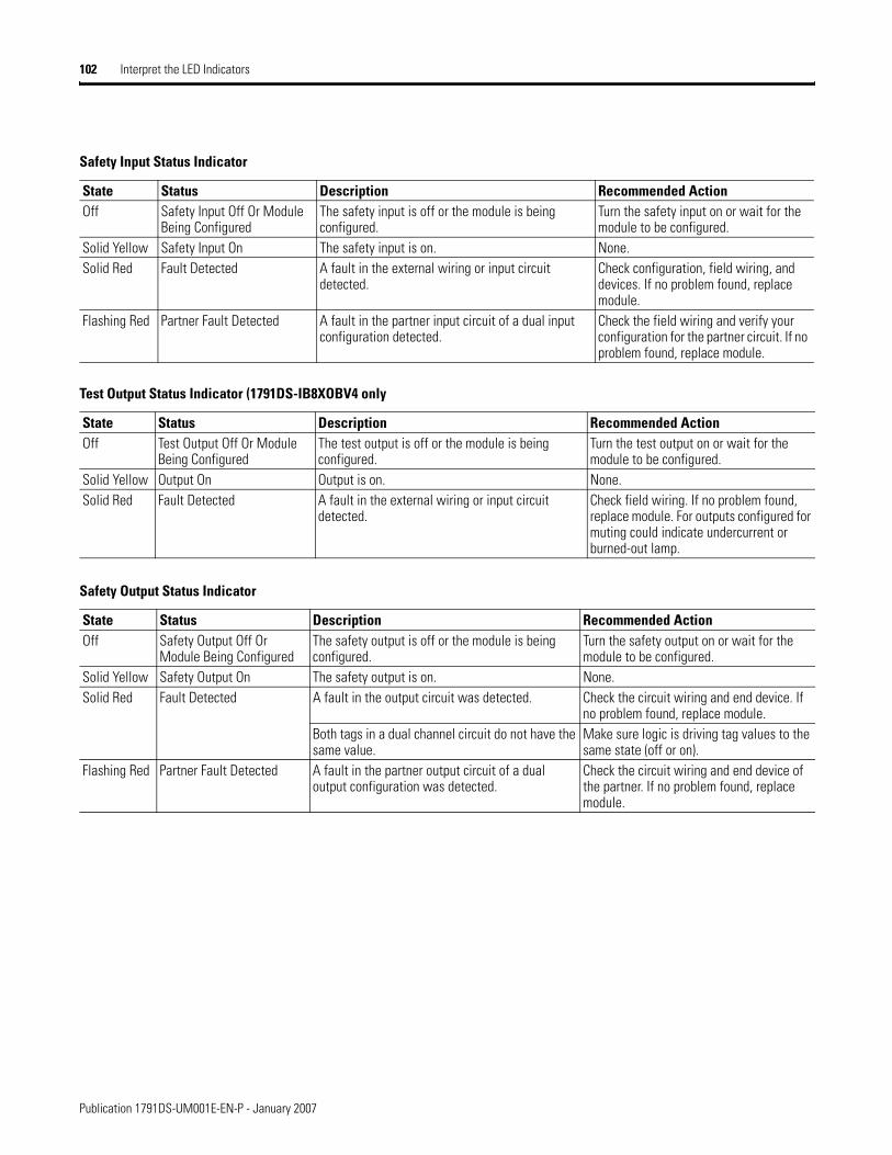
102 Interpret the LED Indicators
Safety Input Status Indicator
State Status Description Recommended ActionOff Safety Input Off Or Module
Being ConfiguredThe safety input is off or the module is being configured.
Turn the safety input on or wait for the module to be configured.
Solid Yellow Safety Input On The safety input is on. None.Solid Red Fault Detected A fault in the external wiring or input circuit
detected.Check configuration, field wiring, and devices. If no problem found, replace module.
Flashing Red Partner Fault Detected A fault in the partner input circuit of a dual input configuration detected.
Check the field wiring and verify your configuration for the partner circuit. If no problem found, replace module.
Test Output Status Indicator (1791DS-IB8XOBV4 only
State Status Description Recommended ActionOff Test Output Off Or Module
Being ConfiguredThe test output is off or the module is being configured.
Turn the test output on or wait for the module to be configured.
Solid Yellow Output On Output is on. None.Solid Red Fault Detected A fault in the external wiring or input circuit
detected.Check field wiring. If no problem found, replace module. For outputs configured for muting could indicate undercurrent or burned-out lamp.
Safety Output Status Indicator
State Status Description Recommended ActionOff Safety Output Off Or
Module Being ConfiguredThe safety output is off or the module is being configured.
Turn the safety output on or wait for the module to be configured.
Solid Yellow Safety Output On The safety output is on. None.Solid Red Fault Detected A fault in the output circuit was detected. Check the circuit wiring and end device. If
no problem found, replace module. Both tags in a dual channel circuit do not have the same value.
Make sure logic is driving tag values to the same state (off or on).
Flashing Red Partner Fault Detected A fault in the partner output circuit of a dual output configuration was detected.
Check the circuit wiring and end device of the partner. If no problem found, replace module.
Publication 1791DS-UM001E-EN-P - January 2007

Chapter 8
Maintain Your Modules
What This Chapter Contains This chapter includes information about troubleshooting and maintenance.
Troubleshoot I/O errors can be read from safety input status, test output status, and safety output status indicators.
• Status data when I/O is normal (OK): ON (1)
• Status data when a fault (Alarm) occurs I/O: OFF (0)
The details of errors can be read by using explicit messages.
See the tables that show safety input errors, test output errors, and safety output errors.
IMPORTANT For I/O error latch-time settings, the OFF status is maintained for at least the error latch time (0…65,530 ms, in increments of 10 ms) when individual safety-input status turns OFF.
103 Publication 1791DS-UM001E-EN-P - January 2007
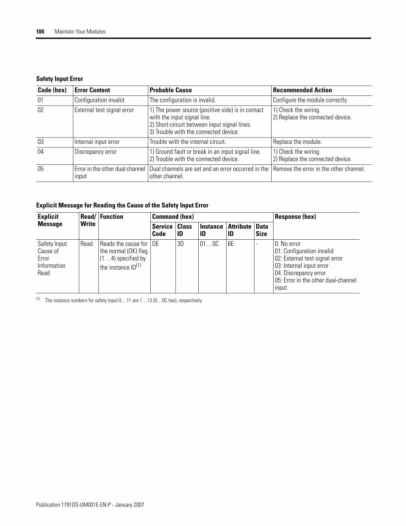
104 Maintain Your Modules
Safety Input Error
Code (hex) Error Content Probable Cause Recommended Action01 Configuration invalid The configuration is invalid. Configure the module correctly. 02 External test signal error 1) The power source (positive side) is in contact
with the input signal line.2) Short-circuit between input signal lines.3) Trouble with the connected device.
1) Check the wiring. 2) Replace the connected device.
03 Internal input error Trouble with the internal circuit. Replace the module.04 Discrepancy error 1) Ground fault or break in an input signal line.
2) Trouble with the connected device.1) Check the wiring. 2) Replace the connected device.
05 Error in the other dual channel input
Dual channels are set and an error occurred in the other channel.
Remove the error in the other channel.
Explicit Message for Reading the Cause of the Safety Input Error
ExplicitMessage
Read/Write
Function Command (hex) Response (hex)Service Code
ClassID
Instance ID
Attribute ID
Data Size
Safety Input Cause of Error Information Read
Read Reads the cause for the normal (OK) flag (1…4) specified by the instance ID(1)
OE 3D 01…0C 6E - 0: No error01: Configuration invalid02: External test signal error03: Internal input error04: Discrepancy error05: Error in the other dual-channel input
(1) The instance numbers for safety input 0…11 are 1…12 (0…0C hex), respectively.
Publication 1791DS-UM001E-EN-P - January 2007
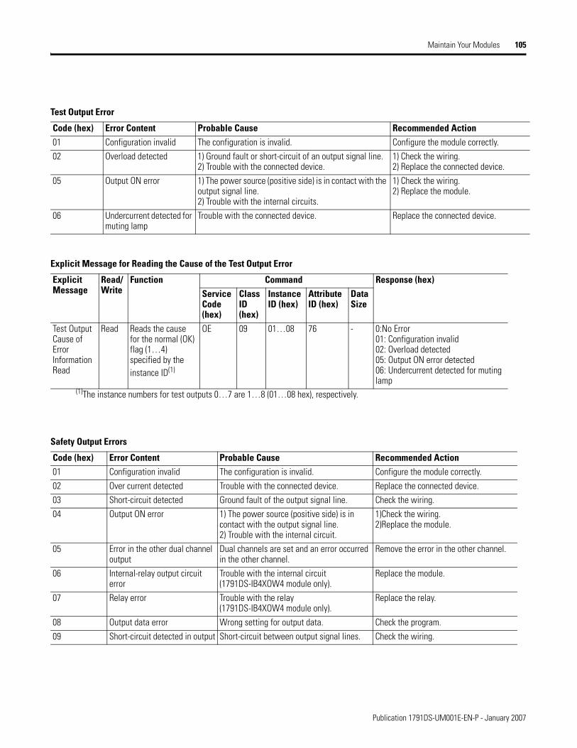
Maintain Your Modules 105
Test Output Error
Code (hex) Error Content Probable Cause Recommended Action01 Configuration invalid The configuration is invalid. Configure the module correctly.02 Overload detected 1) Ground fault or short-circuit of an output signal line.
2) Trouble with the connected device.1) Check the wiring.2) Replace the connected device.
05 Output ON error 1) The power source (positive side) is in contact with the output signal line.2) Trouble with the internal circuits.
1) Check the wiring.2) Replace the module.
06 Undercurrent detected for muting lamp
Trouble with the connected device. Replace the connected device.
Explicit Message for Reading the Cause of the Test Output Error
ExplicitMessage
Read/Write
Function Command Response (hex)Service Code (hex)
ClassID (hex)
Instance ID (hex)
Attribute ID (hex)
Data Size
Test OutputCause of ErrorInformationRead
Read Reads the causefor the normal (OK) flag (1…4) specified by the instance ID(1)
OE 09 01…08 76 - 0:No Error01: Configuration invalid02: Overload detected05: Output ON error detected 06: Undercurrent detected for muting lamp
(1)The instance numbers for test outputs 0…7 are 1…8 (01…08 hex), respectively.
Safety Output Errors
Code (hex) Error Content Probable Cause Recommended Action01 Configuration invalid The configuration is invalid. Configure the module correctly.02 Over current detected Trouble with the connected device. Replace the connected device.03 Short-circuit detected Ground fault of the output signal line. Check the wiring.04 Output ON error 1) The power source (positive side) is in
contact with the output signal line.2) Trouble with the internal circuit.
1)Check the wiring.2)Replace the module.
05 Error in the other dual channel output
Dual channels are set and an error occurred in the other channel.
Remove the error in the other channel.
06 Internal-relay output circuit error
Trouble with the internal circuit (1791DS-IB4XOW4 module only).
Replace the module.
07 Relay error Trouble with the relay (1791DS-IB4XOW4 module only).
Replace the relay.
08 Output data error Wrong setting for output data. Check the program.09 Short-circuit detected in output Short-circuit between output signal lines. Check the wiring.
Publication 1791DS-UM001E-EN-P - January 2007
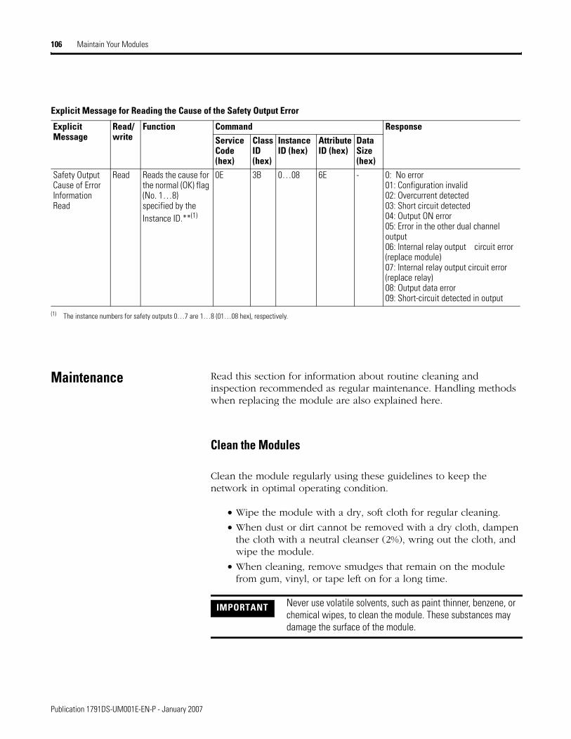
106 Maintain Your Modules
Maintenance Read this section for information about routine cleaning and inspection recommended as regular maintenance. Handling methods when replacing the module are also explained here.
Clean the Modules
Clean the module regularly using these guidelines to keep the network in optimal operating condition.
• Wipe the module with a dry, soft cloth for regular cleaning.
• When dust or dirt cannot be removed with a dry cloth, dampen the cloth with a neutral cleanser (2%), wring out the cloth, and wipe the module.
• When cleaning, remove smudges that remain on the module from gum, vinyl, or tape left on for a long time.
Explicit Message for Reading the Cause of the Safety Output Error
ExplicitMessage
Read/write
Function Command ResponseService Code (hex)
ClassID (hex)
Instance ID (hex)
Attribute ID (hex)
Data Size (hex)
Safety OutputCause of ErrorInformationRead
Read Reads the cause for the normal (OK) flag (No. 1…8) specified by the Instance ID.**(1)
0E 3B 0…08 6E - 0: No error01: Configuration invalid02: Overcurrent detected03: Short circuit detected04: Output ON error05: Error in the other dual channel output06: Internal relay output circuit error (replace module) 07: Internal relay output circuit error (replace relay)08: Output data error09: Short-circuit detected in output
(1) The instance numbers for safety outputs 0…7 are 1…8 (01…08 hex), respectively.
IMPORTANT Never use volatile solvents, such as paint thinner, benzene, or chemical wipes, to clean the module. These substances may damage the surface of the module.
Publication 1791DS-UM001E-EN-P - January 2007
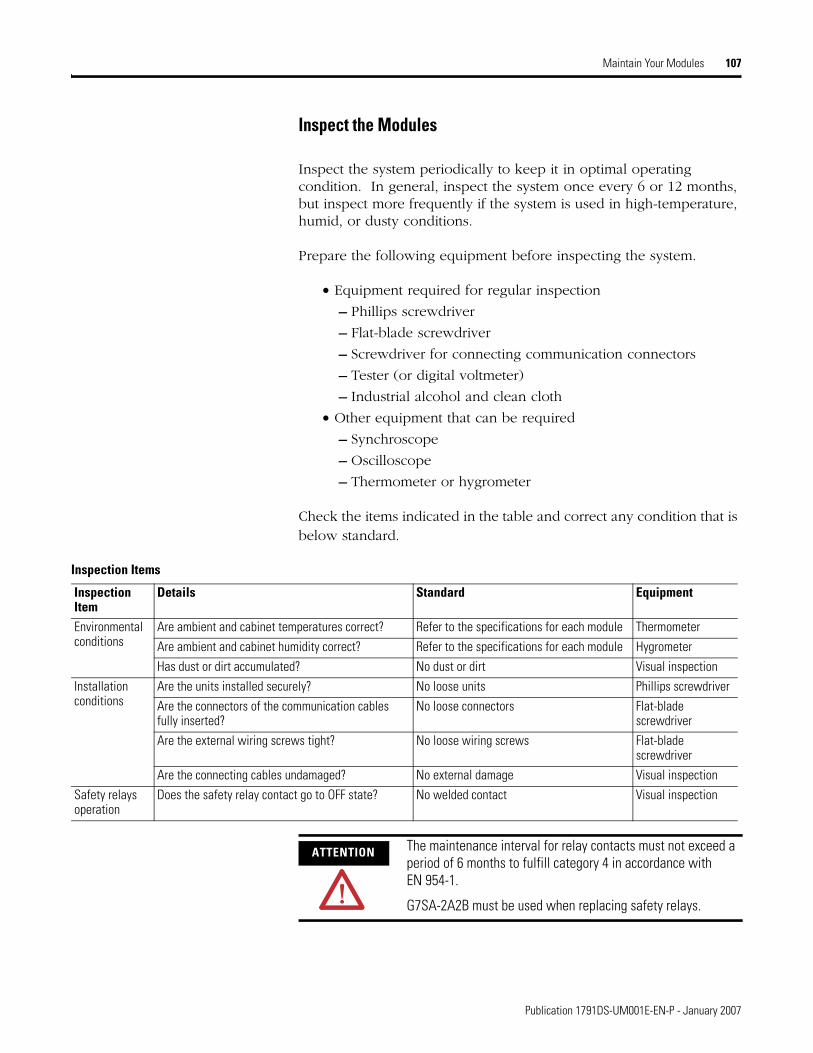
Maintain Your Modules 107
Inspect the Modules
Inspect the system periodically to keep it in optimal operating condition. In general, inspect the system once every 6 or 12 months, but inspect more frequently if the system is used in high-temperature, humid, or dusty conditions.
Prepare the following equipment before inspecting the system.
• Equipment required for regular inspection
– Phillips screwdriver
– Flat-blade screwdriver
– Screwdriver for connecting communication connectors
– Tester (or digital voltmeter)
– Industrial alcohol and clean cloth
• Other equipment that can be required
– Synchroscope
– Oscilloscope
– Thermometer or hygrometer
Check the items indicated in the table and correct any condition that is below standard.
Inspection Items
Inspection Item
Details Standard Equipment
Environmental conditions
Are ambient and cabinet temperatures correct? Refer to the specifications for each module ThermometerAre ambient and cabinet humidity correct? Refer to the specifications for each module HygrometerHas dust or dirt accumulated? No dust or dirt Visual inspection
Installation conditions
Are the units installed securely? No loose units Phillips screwdriverAre the connectors of the communication cables fully inserted?
No loose connectors Flat-blade screwdriver
Are the external wiring screws tight? No loose wiring screws Flat-blade screwdriver
Are the connecting cables undamaged? No external damage Visual inspectionSafety relays operation
Does the safety relay contact go to OFF state? No welded contact Visual inspection
ATTENTION The maintenance interval for relay contacts must not exceed a period of 6 months to fulfill category 4 in accordance with EN 954-1.
G7SA-2A2B must be used when replacing safety relays.
Publication 1791DS-UM001E-EN-P - January 2007

108 Maintain Your Modules
Replace Modules
The network consists of the DeviceNet master unit and safety I/O modules. The entire network is affected when a safety I/O module is faulty, so a faulty module must be repaired or replaced quickly. We recommend having spare modules available to restore network operation as quickly as possible.
Observe the following precautions when replacing a faulty module.
• After replacement, be sure there are no errors with the new module.
• When returning a module for repair, attach a detailed description of the problem and return the module to your Rockwell Automation representative.
• If there is a faulty contact, wipe the contact with a clean, lint-free cloth dampened with alcohol.
After replacing a module, set the new module’s switches to the same settings that were on the old module. For related information see the following publications.
• GuardLogix Controllers User Manual, publication 1756-UM020, for information on replacing a module in the system
• GuardLogix Controller Systems Safety Reference Manual, publication 1756-RM093, for safety considerations when replacing I/O
IMPORTANT Perform a system test of the related safety functions after replacing a module.
Publication 1791DS-UM001E-EN-P - January 2007

Appendix A
DeviceNet Explicit Messages
What This Appendix Contains
This appendix lists DeviceNet explicit messages sent from the master unit to a safety I/O module that you can use to read or write any parameter of a specified safety I/O module. The safety I/O module processes the commands sent from the master and then returns responses.
Basic Format of Explicit Messages
The basic format of each command and response is as follows.
• Destination Node Address - The node address of the module that is sending the explicit messages is specified with a 1 byte hexadecimal.
• Service Code, Class ID, Instance ID, Attribute ID - The parameters used for specifying the command, processing object, and processing content.
• Data - Data is not required when the read command is used.
Response block information is as follows.
• Number of Bytes Received - The number of bytes received from the source node address is returned in hexadecimal. When an error response is returned for an explicit message, the number of bytes is always 0004 hex.
• Source Node Address - The node address of the node from which the command was sent is returned in hexadecimal.
Command Block
Destination Node Address
Service Code Class ID Instance ID Attribute ID Data
Normal Response Block
Number of Bytes Received Source Node Address Service Code Data
Error Response Block
Number of Bytes Received 0004 hex (fixed)
Source Node Address
Service Code
Error Code
109 Publication 1791DS-UM001E-EN-P - January 2007
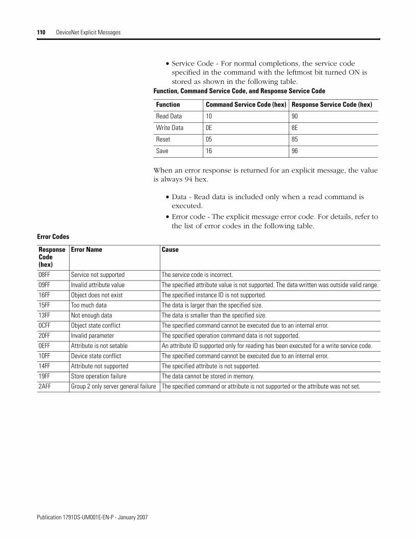
110 DeviceNet Explicit Messages
• Service Code - For normal completions, the service code specified in the command with the leftmost bit turned ON is stored as shown in the following table.
When an error response is returned for an explicit message, the value is always 94 hex.
• Data - Read data is included only when a read command is executed.
• Error code - The explicit message error code. For details, refer to the list of error codes in the following table.
Function, Command Service Code, and Response Service Code
Function Command Service Code (hex) Response Service Code (hex)
Read Data 10 90
Write Data 0E 8E
Reset 05 85
Save 16 96
Error Codes
Response Code (hex)
Error Name Cause
08FF Service not supported The service code is incorrect.09FF Invalid attribute value The specified attribute value is not supported. The data written was outside valid range.16FF Object does not exist The specified instance ID is not supported.15FF Too much data The data is larger than the specified size.13FF Not enough data The data is smaller than the specified size.0CFF Object state conflict The specified command cannot be executed due to an internal error.20FF Invalid parameter The specified operation command data is not supported.0EFF Attribute is not setable An attribute ID supported only for reading has been executed for a write service code.10FF Device state conflict The specified command cannot be executed due to an internal error.14FF Attribute not supported The specified attribute is not supported.19FF Store operation failure The data cannot be stored in memory.2AFF Group 2 only server general failure The specified command or attribute is not supported or the attribute was not set.
Publication 1791DS-UM001E-EN-P - January 2007
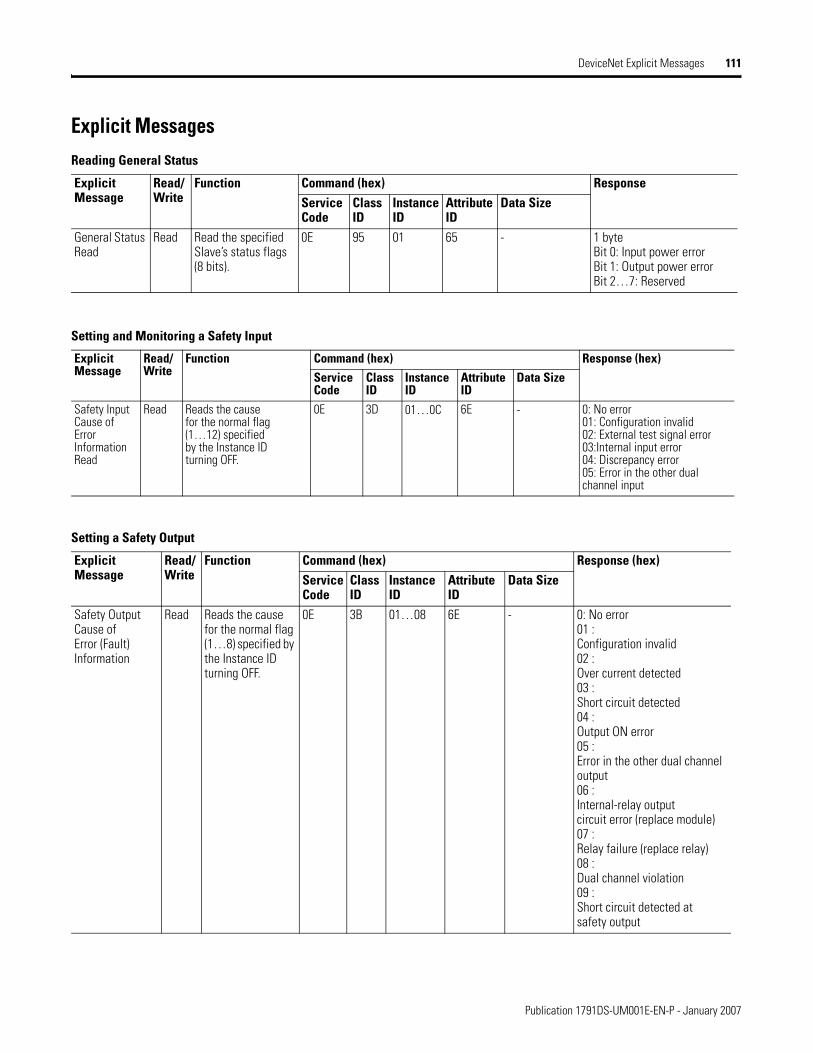
DeviceNet Explicit Messages 111
Explicit MessagesReading General Status
Explicit Message
Read/Write
Function Command (hex) ResponseServiceCode
ClassID
Instance ID
Attribute ID
Data Size
General Status Read
Read Read the specified Slave’s status flags (8 bits).
0E 95 01 65 - 1 byteBit 0: Input power errorBit 1: Output power errorBit 2…7: Reserved
Setting and Monitoring a Safety Input
Explicit Message
Read/Write
Function Command (hex) Response (hex)Service Code
ClassID
Instance ID
Attribute ID
Data Size
Safety Input Cause of Error Information Read
Read Reads the cause for the normal flag (1…12) specified by the Instance ID turning OFF.
0E 3D 01…0C 6E - 0: No error 01: Configuration invalid02: External test signal error03:Internal input error04: Discrepancy error05: Error in the other dual channel input
Setting a Safety Output
Explicit Message
Read/Write
Function Command (hex) Response (hex)Service Code
ClassID
Instance ID
Attribute ID
Data Size
Safety OutputCause of Error (Fault) Information
Read Reads the cause for the normal flag (1…8) specified by the Instance ID turning OFF.
0E 3B 01…08 6E - 0: No error01 : Configuration invalid02 : Over current detected03 : Short circuit detected04 : Output ON error05 : Error in the other dual channel output06 : Internal-relay outputcircuit error (replace module)07 : Relay failure (replace relay)08 : Dual channel violation09 : Short circuit detected at safety output
Publication 1791DS-UM001E-EN-P - January 2007

112 DeviceNet Explicit Messages
Monitoring the Test Output Point
Explicit Message
Read/Write
Function Command (hex) Response (hex)Service Code
ClassID
Instance ID
Attribute ID
Data Size
Safety OutputCause of Error (Fault)Information
Read Reads the cause forthe normal flag (1…8) specified by the Instance ID turning OFF.
0E 09 01…04 6E - 0 = No error01 : Configuration invalid02 : Overload detected03 : Cross circuit detected05 : Output ON error06 : Undercurrent detected for muting lamp
Setting Hold/Clear for Communication Errors (Test Output)
Explicit Message Read/Write
Function Command (hex) Response (hex)Service
Code ClassID
Instance ID
Attribute ID
Data Size
Setting for Output Status (Hold or Clear) after Communication Error
Read Reads whether hold or clear is set as the output status after a communication error for an output specified by the instance ID. The setting can be read for a specified number of points.
0E 09 01…08 05 - 1 byte
00 : Clear
01 : Hold
Setting for Output Status (Hold or Clear) after Communication Error
Write Sets whether hold or clear as the output status after acommunication errorfor an output specified by the instance ID. Thesetting can be readfor a specifiednumber of points.
10 09 01…08 05 1 byte
00 : Clear
01 : Hold
Publication 1791DS-UM001E-EN-P - January 2007

Appendix B
Probability of Failure on Demand (PFD), Probability of Failure per Hour (PFH), and Mean Time Between (MTBF) Data
What This Appendix Contains
This appendix lists calculated values for probability of failure on demand, probability of failure per hour, and mean time between failure.
Calculated Values See the table that shows the values.
Calculated values of probability of failure on demand and probability of failure per hour appear in the table and must be calculated for the overall devices within the system to comply with the SIL level required for application.
Within the proof test interval, every I/O module must be functionally tested by individually toggling each input point and verifying that it is detected by the controller. Additionally, each output point must be individually toggled by the controller and user-verified that the output point changes state.
IMPORTANT The proof test interval of the 1791DS-IB4XOW4 module must not exceed 0.5 years because the maintenance interval for the relay contacts must not exceed a period of 6 months to satisfy safety category 4 in accordance with EN954-1.
Calculated Values for Probability of Failure on Demand (PFD) - 1791DS-IB12, 1791DS-IB8XOB8, 1791DS-IB4XOW4
Proof Test Interval 1791DS-IB12 1791DS-IB8XOB8 1791DS-IB4XOW4Years Hours0.25 2190 2.202E-07 2.213E-07 4.697E-060.5 4380 4.384E-07 4.395E-07 9.532E-061 8760 8.757E-07 8.768E-07 1.963E-052 17,520 1.754E-06 1.755E-06 4.151E-055 43,800 4.419E-06 4.421E-06 1.207E-0410 87,600 8.962E-06 8.963E-06 2.978E-04
113 Publication 1791DS-UM001E-EN-P - January 2007

114 Probability of Failure on Demand (PFD), Probability of Failure per Hour (PFH), and Mean Time Between (MTBF) Data
Calculated Values for Probability of Failure per Hour (PFH) - 1791DS-IB12, 1791DS-IB8XOB8, 1791DS-IB4XOW4
Calculated Values for Mean Time Between Failure (MTBF) - 1791DS-IB12, 1791DS-IB8XOB8, 1791DS-IB4XOW4
Calculated Values for Probability of Failure on Demand (PFD), Probability of Failure per Hour (PFH), and Mean Time Between Failure (MTBF) - SIL 3 - 1791DS-IB8XOBV4, 1732DS-IB8XOBV4, 1791DS-IB16
Proof Test Interval 1791DS-IB12 1791DS-IB8XOB8 1791DS-IB4XOW4Year Hour0.25 2190 2.009E-10 2.019E-10 4.201E-090.5 4380 1.999E-10 2.004E-10 4.200E-091 8760 1.994E-10 1.996E-10 4.199E-092 17,520 1.991E-10 1.992E-10 4.199E-09
Model MTBF (hour)1791DS-IB12 4.02E+051791DS-IB8XOB8 2.64+051791DS-IB4XOW4 1.44E+05
Model Proof Test Interval PFD PFH (1/hour)
MTBF (hour)Year Hour
1791DS-IB8XOBV4
1 8760 8.73E-07 2.00E-10 2.36E+062 17,520 1.75E-065 43,800 4.37E-0610 87,600 8.74E-06
1732DS-IB8XOBV4
1 8760 8.73E-07 2.00E-10 2.36E+062 17,520 1.75E-065 43,800 4.37E-0610 87,600 8.74E-06
1791DS-IB16 1 8760 8.49E-07 1.94E-10 2.42E+062 17520 1.70E-065 43800 4.25E-0610 87600 8.50E-06
Publication 1791DS-UM001E-EN-P - January 2007

Appendix C
List of Functions
What This Appendix Contains
This appendix lists functions for the safety I/O modules including safety inputs, test outputs, and safety outputs.
List of Functions
Safety I/O Modules
Item DescriptionSelf-diagnosis Function Self-diagnosis is performed when power is turned ON and periodically during operation.
When an error occurs, it is treated as a fatal error, the MS indicator lights in red, and all safety output and output data to the network turn OFF.
Configuration Lock (Applies to RSNetWorx Software, Does not Apply to RSLogix 5000 Software)
After configuration data has been downloaded and verified, configuration data within the module can be protected. When the data is protected, the LOCK indicator on the front panel lights in yellow.When the data is not protected, the LOCK indicator on the front panel flashes in yellow.
Automatic Baud Rate Detection
The module is automatically set to the communication rate of the network.
Contents of Remote I/O Communication
I/O Data for Control Safety Inputs The ON/OFF state of each safety input terminal
1791DS -> DeviceNet master Safety Master
Safety Outputs The ON/OFF state of each safety output terminal
Safety Master -> 1791DS
Standard Outputs The ON/OFF state of each test output terminal (T0…T3)
DeviceNet Master or Safety Master -> 1791DS
Output Readback Safety Output Monitors
The actual On/OFF state of each safety output 1791DS -> DeviceNet Master Safety MasterStatus Data Individual Safety
Input StatusIndividual Point Input Status (ON = OK, OFF = Fault)
Combined Safety Input Status
Combined Input Status (ON = OK, OFF = Fault)
Individual Safety Output Status
Individual Point Output Status (ON = OK, OFF = Fault)
Combined Safety Output Status
Combined Output Status (ON = OK, OFF = Fault)
Individual Test Output Status
Individual Test Output Status (ON = OK, OFF = Fault)
Muting Lamp Status Muting Lamp Status of T3(ON = OK, OFF = Fault) if T3 is configured for muting lamp operation
115 Publication 1791DS-UM001E-EN-P - January 2007
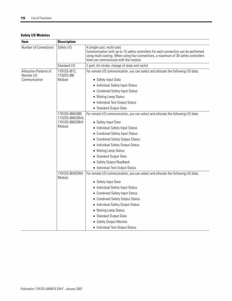
116 List of Functions
Number of Connections Safety I/O 4 (single-cast, multi-cast) Communication with up to 15 safety controllers for each connection can be performed using multi-casting. When using four connections, a maximum of 30 safety controllers total can communicate with the module.
Standard I/O 2 (poll, bit-strobe, change of state and cyclic)Allocation Patterns of Remote I/O Communication
1791DS-IB12, 1732DS-IB8 Module
For remote I/O communication, you can select and allocate the following I/O data:
• Safety Input Data
• Individual Safety Input Status
• Combined Safety Input Status
• Muting Lamp Status
• Individual Test Output Status
• Standard Output Data 1791DS-IB8XOB8. 1732DS-IB8XOBV4, 1791DS-IB8SOBV4 Module
For remote I/O communication, you can select and allocate the following I/O data:
• Safety Input Data
• Individual Safety Input Status
• Combined Safety Input Status
• Combined Safety Output Status
• Individual Safety Output Status
• Muting Lamp Status
• Standard Output Data
• Safety Output Readback
• Individual Test Output Status1791DS-IB4XOW4 Module
For remote I/O communication, you can select and allocate the following I/O data:
• Safety Input Data
• Individual Safety Input Status
• Combined Safety Input Status
• Combined Safety Output Status
• Individual Safety Output Status
• Muting Lamp Status
• Standard Output Data
• Safety Output Monitor
• Individual Test Output Status
Safety I/O Modules
Item Description
Publication 1791DS-UM001E-EN-P - January 2007

List of Functions 117
Safety Inputs
Item DescriptionInput Channel Mode Any of the following modes can be selected according to the external input device for each input.
• Not used - An external input device is not connected.• Safety pulse test - Used with a contact output device in combination with a test output. Using this
setting, short circuits between input signal lines and the power supply (positive side) and short circuits between input signal lines can be detected.
• Safety - A solid-state output safety sensor is connected.• Standard - A standard device is connected, for example, a reset switch.
Dual-channel Mode The consistency between signals on two channels can be evaluated. The following settings can be selected. The discrepancy time is set for Dual-channel operation.
• Single channel - Used as a single channel. • Dual-channel equivalent - Used as a dual channel pair. Status is OK when both channels are ON or
OFF.• Dual-channel complementary - Used as dual channel. Status is OK when one channel is ON and the
other channel is OFF.
Input Delays ON delay - An input signal is treated as being OFF during the ON delay setting time (0…126 ms, in increments of 6 ms) after the input contact’s rising edge. The input turns ON only if the input contact remains ON after the ON delay time has elapsed. This helps prevent chattering of the input contacts. OFF delay - An input signal is treated as being ON during the OFF delay setting time (0…126 ms, in increments of 6 ms) after the input contact’s falling edge.
The input turns OFF only if the input contact remains OFF after the OFF delay time has elapsed.
This helps prevent chattering of the input contacts. Input Error Latch Time An input or test output error is held for a minimum of this amount of time.
This time should be set to ensure that the Safety Controller recognizes the error (0…65,530 ms, in increments of 10 ms).
Publication 1791DS-UM001E-EN-P - January 2007

118 List of Functions
Test Outputs
Item Description
Test Output Mode Any of the following modes can be selected to accomodate the connected external device.
Not used - An external device is not connected.
Standard output - The output is connected to a standard device.
Pulse test output - A contact output device is connected and used in combination with a safety input.
Power supply output - The power supply terminals of a safety sensor are connected.The voltage supplied to I/O power (V,G) is output from the test output terminal.Muting lamp output (terminal T3 or T7, depending on module type) - An indicator is connected.Unit is turned on to detect broken lines in an external indicator..
Output Status AfterCommunicationError
A selection to hold or clear the previous value when a communication error occurs is available.
Short CircuitDetection
Supported.
Broken WireDetection ofExternal Indicator
Supported for muting output only.
Safety Output
Item Description
Output Channel Mode Any of the following Safety Output modes can be selected.
• Not used - External output devices are not connected.
• Safety - When the safety output is ON, the test pulse is not output (remains ON).
• Safety pulse test - When the output is ON, the test pulse is turned OFF for 470 µs in a cycle of 648 ms. Using this function, short-circuits between output signal lines and the power supply (positive side) and short-circuits between output signal lines can be detected.
Dual Channel Setting The consistency between signals on two channels can be evaluated.Either of the following settings can be selected for 1791DS-1791DS-IB8XOB8 and 1791DS-IB4XOW4. Dual-channel is the only setting for 1791DS-IB8XOBV4 and 1732DS-IB8XOBV4.
• Single channel - used as single channel.
• Dual channel - when both channels are OK, outputs can be turned ON. If an error is detected on one of the channels, the other channel is also turned OFF.
Output Error Latch Time A safety output error will be held for a minimum of this amount of time. This time should be set to be sure that the safety controller recognizes the error. (0…65,530 ms, in increments of 10 ms)
Short-circuit Protecton Supported.Overcurrent Detection Supported.
Publication 1791DS-UM001E-EN-P - January 2007

Appendix D
Configuration Reference Information
What This Appendix Contains
This appendix provides information about configuration settings.
Understand Parameter Groups
The modules have these parameter groups: general parameters, safety input, test output, and safety output.
See the tables for the settings in each parameter group. All parameters are set by using RSLogix 5000 or RSNetWorx for DeviceNet software.
IMPORTANT Parameters directly related to safety are marked with an X in the left column.
General Parameters
Parameter Name Value Description Defaultx Safety Output Error Latch
Time0…65,530 ms(in increments of 10 ms)
Safety output errors will be latched for this time. 1000 ms
x Safety Input Error Latch Time
0…65,530 ms(in increments of 10 ms)
Safety input or test output errors will be latched for this time.
1000 ms
Test Output Idle State Clear OFF or Keep Output Data
Definition of output data is in idle state. Clear OFF
119 Publication 1791DS-UM001E-EN-P - January 2007
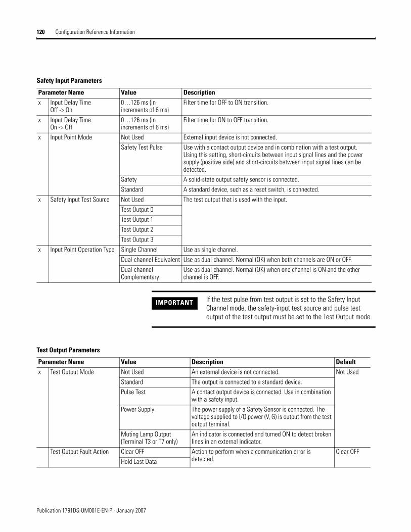
120 Configuration Reference Information
Safety Input Parameters
Parameter Name Value Descriptionx Input Delay Time
Off -> On0…126 ms (in increments of 6 ms)
Filter time for OFF to ON transition.
x Input Delay TimeOn -> Off
0…126 ms (in increments of 6 ms)
Filter time for ON to OFF transition.
x Input Point Mode Not Used External input device is not connected.Safety Test Pulse Use with a contact output device and in combination with a test output.
Using this setting, short-circuits between input signal lines and the power supply (positive side) and short-circuits between input signal lines can be detected.
Safety A solid-state output safety sensor is connected.Standard A standard device, such as a reset switch, is connected.
x Safety Input Test Source Not Used The test output that is used with the input.Test Output 0Test Output 1Test Output 2Test Output 3
x Input Point Operation Type Single Channel Use as single channel.Dual-channel Equivalent Use as dual-channel. Normal (OK) when both channels are ON or OFF.Dual-channel Complementary
Use as dual-channel. Normal (OK) when one channel is ON and the other channel is OFF.
IMPORTANT If the test pulse from test output is set to the Safety Input Channel mode, the safety-input test source and pulse test output of the test output must be set to the Test Output mode.
Test Output Parameters
Parameter Name Value Description Defaultx Test Output Mode Not Used An external device is not connected. Not Used
Standard The output is connected to a standard device. Pulse Test A contact output device is connected. Use in combination
with a safety input.Power Supply The power supply of a Safety Sensor is connected. The
voltage supplied to I/O power (V, G) is output from the test output terminal.
Muting Lamp Output (Terminal T3 or T7 only)
An indicator is connected and turned ON to detect broken lines in an external indicator.
Test Output Fault Action Clear OFF Action to perform when a communication error is detected.
Clear OFFHold Last Data
Publication 1791DS-UM001E-EN-P - January 2007

Configuration Reference Information 121
Allocate Remote I/O Concerning I/O allocations, the module internally stores I/O data. To set connection paths, use RSLogix 5000 or RSNetWorx for DeviceNet software to allocate I/O data for the master unit. No settings are made by default. Be sure to set the required connection paths.
Concerning I/O data, the module stores the following data:
• SAFETY: Information the controller can use in safety-related functions
• STANDARD: Additional information that must not be relied on for safety functions
Safety Output Parameters
Parameter Name Value Description Defaultx Output Point Mode Not Used An external output devices is not connected. Not Used
Safety When the output is ON, the test pulse is not output (remains ON).
Safety Pulse Test Using this function, short-circuits between output signal lines and the power supply (positive side) and short-circuits between output signal lines can be detected.
x Output Point Operation Type
Single Channel Use as single channel. Dual-channelDual-channel Use as dual-channel. When both channels are normal (OK),
outputs can be turned ON.
Publication 1791DS-UM001E-EN-P - January 2007
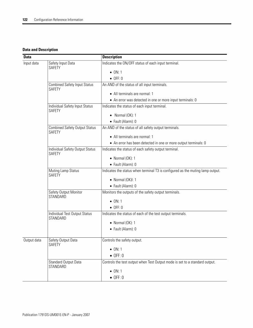
122 Configuration Reference Information
Data and Description
Data DescriptionInput data Safety Input Data
SAFETYIndicates the ON/OFF status of each input terminal.
• ON: 1
• OFF: 0Combined Safety Input StatusSAFETY
An AND of the status of all input terminals.
• All terminals are normal: 1
• An error was detected in one or more input terminals: 0Individual Safety Input StatusSAFETY
Indicates the status of each input terminal.
• Normal (OK): 1
• Fault (Alarm): 0Combined Safety Output StatusSAFETY
An AND of the status of all safety output terminals.
• All terminals are normal: 1
• An error has been detected in one or more output terminals: 0Individual Safety Output StatusSAFETY
Indicates the status of each safety output terminal.
• Normal (OK): 1
• Fault (Alarm): 0Muting Lamp StatusSAFETY
Indicates the status when terminal T3 is configured as the muting lamp output.
• Normal (OK)l: 1
• Fault (Alarm): 0Safety Output MonitorSTANDARD
Monitors the outputs of the safety output terminals.
• ON: 1
• OFF: 0Individual Test Output StatusSTANDARD
Indicates the status of each of the test output terminals.
• Normal (OK): 1
• Fault (Alarm): 0
Output data Safety Output DataSAFETY
Controls the safety output.
• ON: 1
• OFF: 0Standard Output DataSTANDARD
Controls the test output when Test Output mode is set to a standard output.
• ON: 1
• OFF: 0
Publication 1791DS-UM001E-EN-P - January 2007

Configuration Reference Information 123
I/O Data Supported by Each Module
See the tables that show the I/O data supported by each module. Refer to I/O Assembly Data for data arrangements.
For I/O data, safety connections for up to four items, including one output, can be allocated for the master unit, and standard connections for up to two items can be allocated for the master unit (scanner).
Publication 1791DS-UM001E-EN-P - January 2007
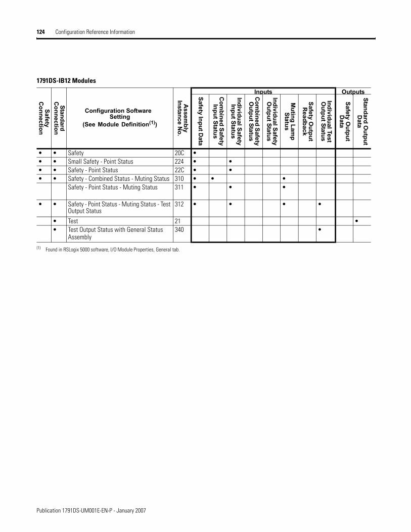
124 Configuration Reference Information
1791DS-IB12 Modules
Safety C
onnection
Standard C
onnection
Configuration Software Setting
(See Module Definition(1))
Assem
bly Instance N
o.
Inputs OutputsSafety Input Data
Com
bined Safety Input Status
Individual Safety Input Status
Com
bined Safety O
utput Status
Individual Safety O
utput Status
Muting Lam
p Status
Safety Output
Readback
Individual Test O
utput Status
Safety Output
Data
Standard Output
Data
• • Safety 20C •• • Small Safety - Point Status 224 • •• • Safety - Point Status 22C • •• • Safety - Combined Status - Muting Status 310 • • •
Safety - Point Status - Muting Status 311 • • •
• • Safety - Point Status - Muting Status - Test Output Status
312 • • • •
• Test 21 •• Test Output Status with General Status
Assembly340 •
(1) Found in RSLogix 5000 software, I/O Module Properties, General tab.
Publication 1791DS-UM001E-EN-P - January 2007
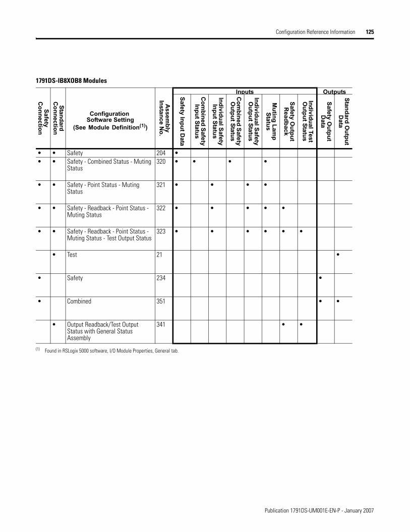
Configuration Reference Information 125
1791DS-IB8XOB8 Modules
Safety C
onnection
Standard C
onnection
Configuration Software Setting
(See Module Definition(1))
Assem
bly Instance N
o.
Inputs OutputsSafety Input Data
Com
bined Safety Input Status
Individual Safety Input Status
Com
bined Safety O
utput Status
Individual Safety O
utput Status
Muting Lam
p Status
Safety Output
Readback
Individual Test O
utput Status
Safety Output
Data
Standard Output
Data
• • Safety 204 •• • Safety - Combined Status - Muting
Status320 • • • •
• • Safety - Point Status - Muting Status
321 • • • •
• • Safety - Readback - Point Status - Muting Status
322 • • • • •
• • Safety - Readback - Point Status - Muting Status - Test Output Status
323 • • • • • •
• Test 21 •
• Safety 234 •
• Combined 351 • •
• Output Readback/Test Output Status with General Status Assembly
341 • •
(1) Found in RSLogix 5000 software, I/O Module Properties, General tab.
Publication 1791DS-UM001E-EN-P - January 2007
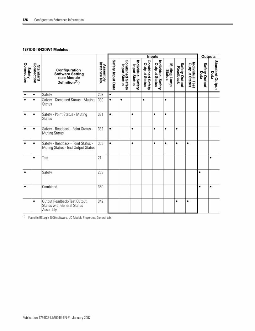
126 Configuration Reference Information
1791DS-IB4XOW4 Modules
Safety C
onnection
Standard C
onnection
Configuration Software Setting
(see Module Definition(1))
Assem
bly Instance N
o.
Inputs OutputsSafety Input Data
Com
bined Safety Input Status
Individual Safety Input Status
Com
bined Safety O
utput Status
Individual Safety O
utput Status
Muting Lam
p Status
Safety Output
Readback
Individual Test O
utput Status
Safety Output
Data
Standard Output
Data
• • Safety 203 •• • Safety - Combined Status - Muting
Status330 • • • •
• • Safety - Point Status - Muting Status
331 • • • •
• • Safety - Readback - Point Status - Muting Status
332 • • • • •
• • Safety - Readback - Point Status - Muting Status - Test Output Status
333 • • • • • •
• Test 21 •
• Safety 233 •
• Combined 350 • •
• Output Readback/Test Output Status with General Status Assembly
342 • •
(1) Found in RSLogix 5000 software, I/O Module Properties, General tab.
Publication 1791DS-UM001E-EN-P - January 2007
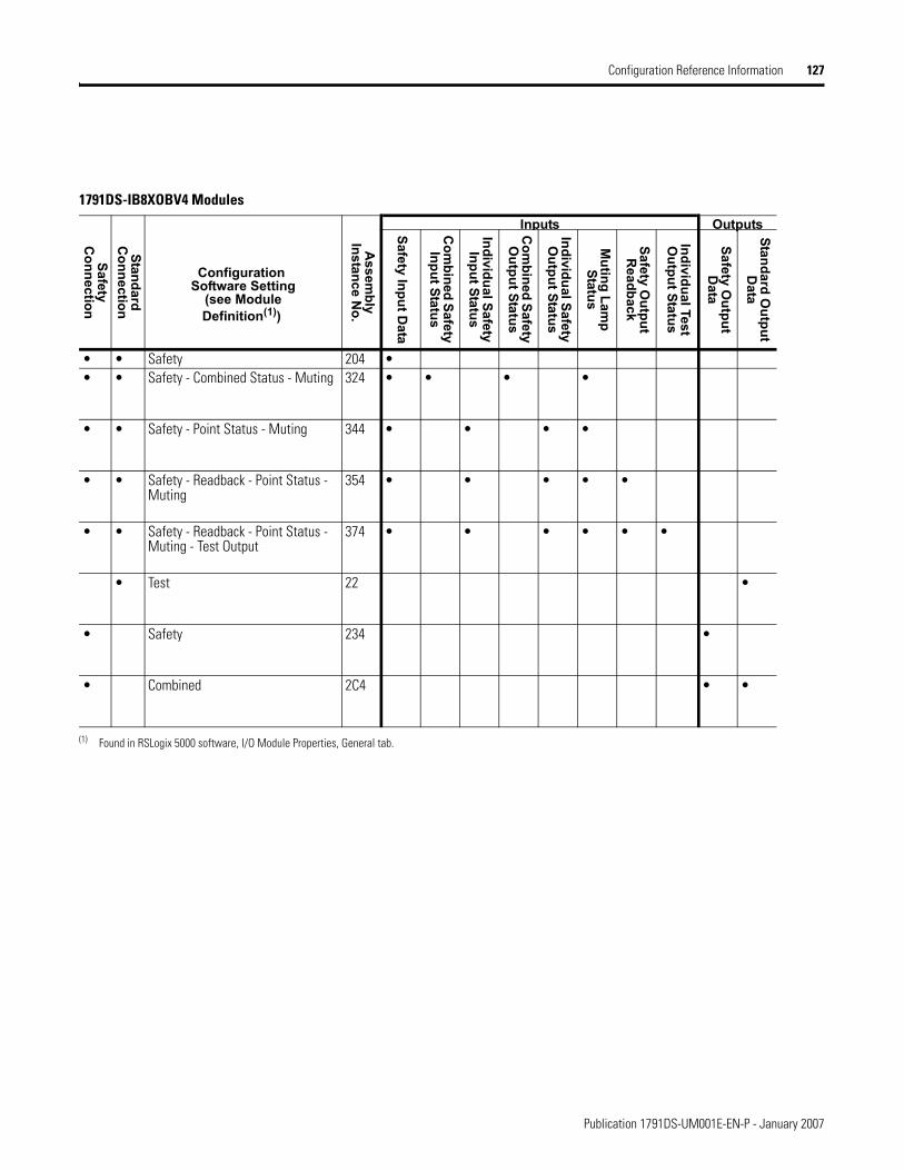
Configuration Reference Information 127
1791DS-IB8XOBV4 Modules
Safety C
onnection
Standard C
onnection
Configuration Software Setting
(see Module Definition(1))
Assem
bly Instance N
o.
Inputs OutputsSafety Input Data
Com
bined Safety Input Status
Individual Safety Input Status
Com
bined Safety O
utput Status
Individual Safety O
utput Status
Muting Lam
p Status
Safety Output
Readback
Individual Test O
utput Status
Safety Output
Data
Standard Output
Data
• • Safety 204 •• • Safety - Combined Status - Muting 324 • • • •
• • Safety - Point Status - Muting 344 • • • •
• • Safety - Readback - Point Status - Muting
354 • • • • •
• • Safety - Readback - Point Status - Muting - Test Output
374 • • • • • •
• Test 22 •
• Safety 234 •
• Combined 2C4 • •
(1) Found in RSLogix 5000 software, I/O Module Properties, General tab.
Publication 1791DS-UM001E-EN-P - January 2007

128 Configuration Reference Information
1732DS-IB8 Modules
Safety C
onnection
Standard C
onnection
Configuration Software Setting
(see Module Definition(1))
Assem
bly Instance N
o.
Inputs OutputsSafety Input Data
Com
bined Safety Input Status
Individual Safety Input Status
Com
bined Safety O
utput Status
Individual Safety O
utput Status
Muting Lam
p Status
Safety Output
Readback
Individual Test O
utput Status
Safety Output
Data
Standard Output
Data
• • Safety 204 •• • Safety - Point Status - Muting
Status334 • • • •
• • Safety - Point Status - Muting - Test Output
364 • • • •
• • Safety - Combined Status - Muting 314 • • • •
• • Safety - Point Status 224 • •
• Test 22 •
(1) Found in RSLogix 5000 software, I/O Module Properties, General tab.
Publication 1791DS-UM001E-EN-P - January 2007

Configuration Reference Information 129
1732DS-IB8XOBV4 Modules
Safety C
onnection
Standard C
onnection
Configuration Software Setting
(see Module Definition(1))
Assem
bly Instance N
o.
Inputs OutputsSafety Input Data
Com
bined Safety Input Status
Individual Safety Input Status
Com
bined Safety O
utput Status
Individual Safety O
utput Status
Muting Lam
p Status
Safety Output
Readback
Individual Test O
utput Status
Safety Output
Data
Standard Output
Data
• • Safety 204 •Safety - Combined Status - Muting 324 • • • •
• • Safety - Point Status - Muting 344 • • • •
• • Safety - Readback - Point Status - Muting
354 • • • • •
• • Safety - Readback - Point Status - Muting - Test Output
374 • • • • • •
• Test 22 •
• Safety 234 •
• Combined 2C4 • •
(1) Found in RSLogix 5000 software, I/O Module Properties, General tab.
Publication 1791DS-UM001E-EN-P - January 2007
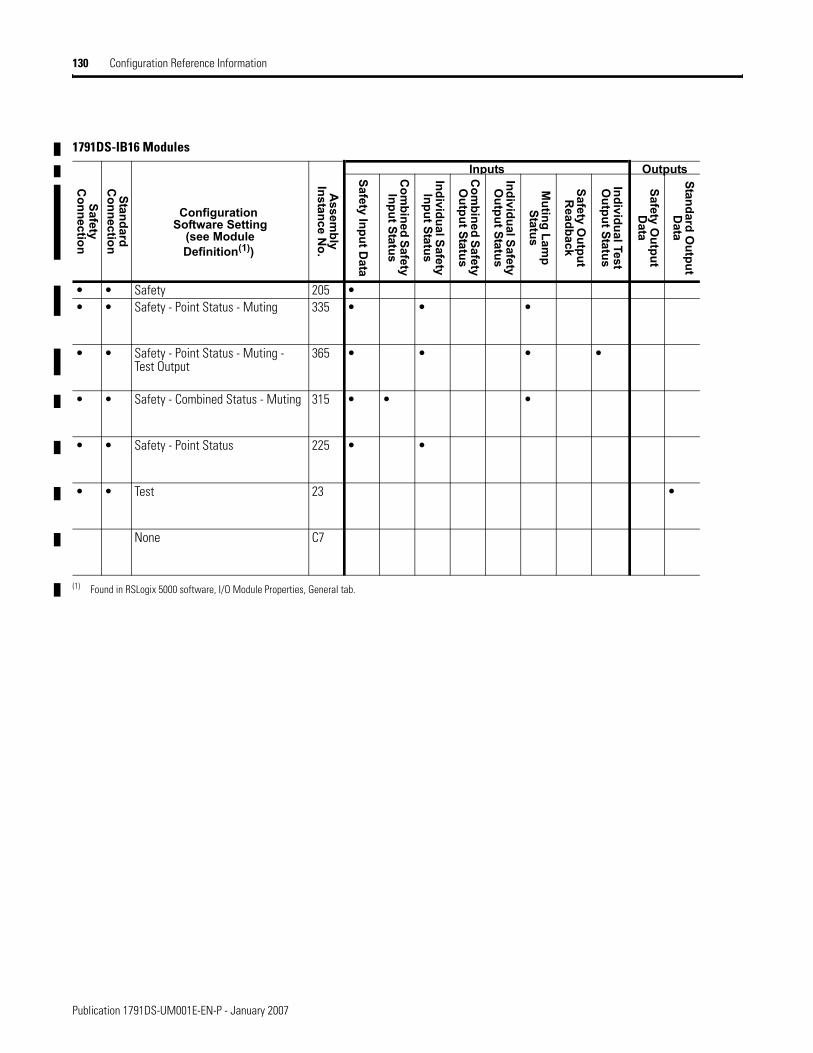
130 Configuration Reference Information
1791DS-IB16 Modules
Safety C
onnection
Standard C
onnection
Configuration Software Setting
(see Module Definition(1))
Assem
bly Instance N
o.
Inputs OutputsSafety Input Data
Com
bined Safety Input Status
Individual Safety Input Status
Com
bined Safety O
utput Status
Individual Safety O
utput Status
Muting Lam
p Status
Safety Output
Readback
Individual Test O
utput Status
Safety Output
Data
Standard Output
Data
• • Safety 205 •• • Safety - Point Status - Muting 335 • • •
• • Safety - Point Status - Muting - Test Output
365 • • • •
• • Safety - Combined Status - Muting 315 • • •
• • Safety - Point Status 225 • •
• • Test 23 •
None C7
(1) Found in RSLogix 5000 software, I/O Module Properties, General tab.
Publication 1791DS-UM001E-EN-P - January 2007
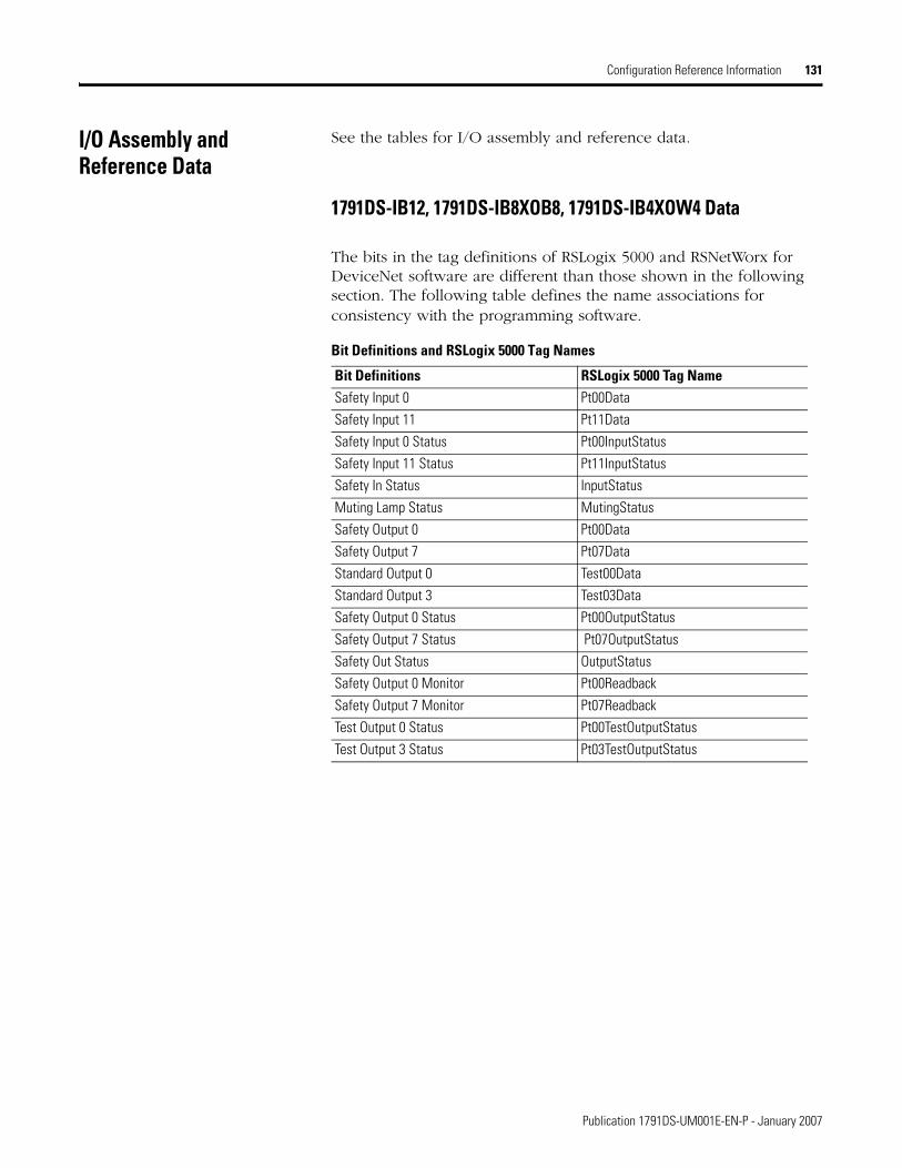
Configuration Reference Information 131
I/O Assembly and Reference Data
See the tables for I/O assembly and reference data.
1791DS-IB12, 1791DS-IB8XOB8, 1791DS-IB4XOW4 Data
The bits in the tag definitions of RSLogix 5000 and RSNetWorx for DeviceNet software are different than those shown in the following section. The following table defines the name associations for consistency with the programming software.
Bit Definitions and RSLogix 5000 Tag Names
Bit Definitions RSLogix 5000 Tag NameSafety Input 0 Pt00DataSafety Input 11 Pt11DataSafety Input 0 Status Pt00InputStatusSafety Input 11 Status Pt11InputStatusSafety In Status InputStatusMuting Lamp Status MutingStatusSafety Output 0 Pt00DataSafety Output 7 Pt07DataStandard Output 0 Test00DataStandard Output 3 Test03DataSafety Output 0 Status Pt00OutputStatusSafety Output 7 Status Pt07OutputStatusSafety Out Status OutputStatusSafety Output 0 Monitor Pt00ReadbackSafety Output 7 Monitor Pt07ReadbackTest Output 0 Status Pt00TestOutputStatusTest Output 3 Status Pt03TestOutputStatus
Publication 1791DS-UM001E-EN-P - January 2007
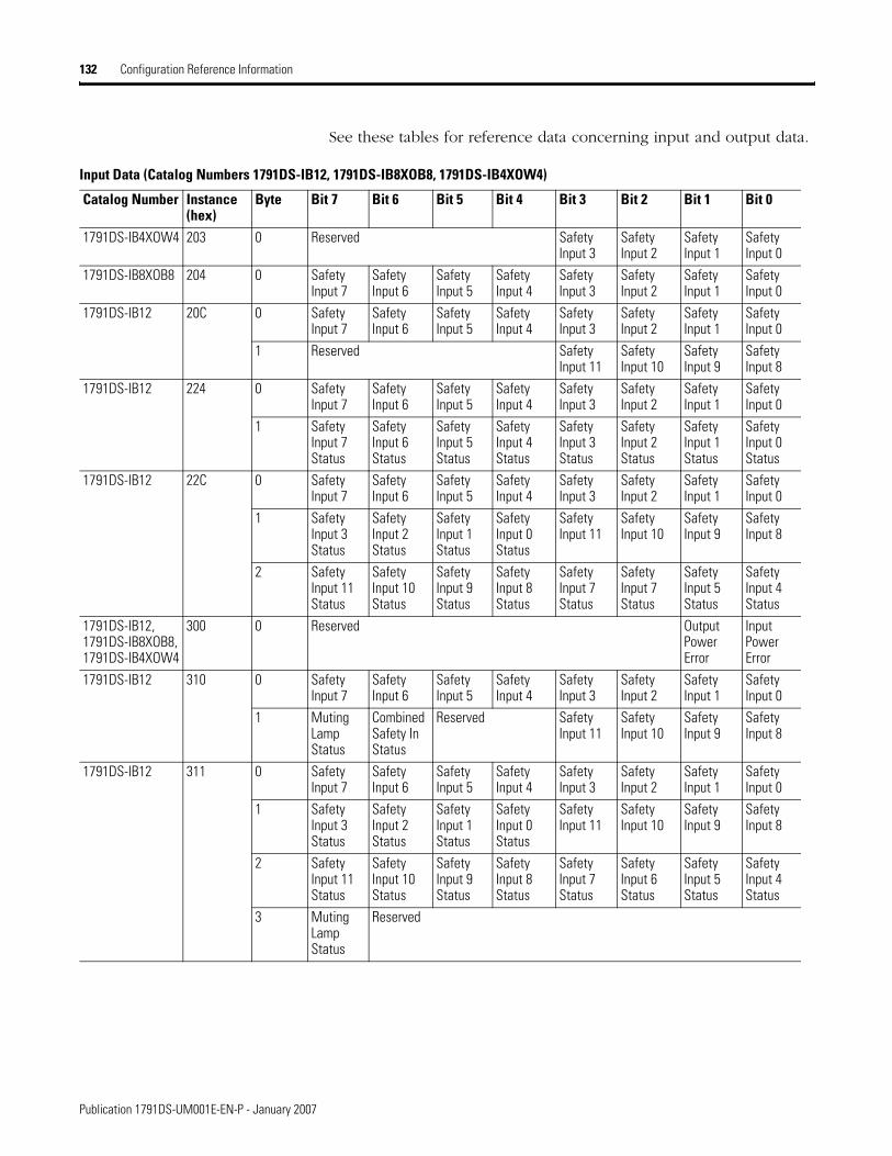
132 Configuration Reference Information
See these tables for reference data concerning input and output data.
Input Data (Catalog Numbers 1791DS-IB12, 1791DS-IB8XOB8, 1791DS-IB4XOW4)
Catalog Number Instance (hex)
Byte Bit 7 Bit 6 Bit 5 Bit 4 Bit 3 Bit 2 Bit 1 Bit 0
1791DS-IB4XOW4 203 0 Reserved Safety Input 3
Safety Input 2
Safety Input 1
Safety Input 0
1791DS-IB8XOB8 204 0 Safety Input 7
Safety Input 6
Safety Input 5
Safety Input 4
Safety Input 3
Safety Input 2
Safety Input 1
Safety Input 0
1791DS-IB12 20C 0 Safety Input 7
Safety Input 6
Safety Input 5
Safety Input 4
Safety Input 3
Safety Input 2
Safety Input 1
Safety Input 0
1 Reserved Safety Input 11
Safety Input 10
Safety Input 9
Safety Input 8
1791DS-IB12 224 0 Safety Input 7
Safety Input 6
Safety Input 5
Safety Input 4
Safety Input 3
Safety Input 2
Safety Input 1
Safety Input 0
1 Safety Input 7 Status
Safety Input 6 Status
Safety Input 5 Status
Safety Input 4 Status
Safety Input 3 Status
Safety Input 2 Status
Safety Input 1 Status
Safety Input 0 Status
1791DS-IB12 22C 0 Safety Input 7
Safety Input 6
Safety Input 5
Safety Input 4
Safety Input 3
Safety Input 2
Safety Input 1
Safety Input 0
1 Safety Input 3 Status
Safety Input 2 Status
Safety Input 1 Status
Safety Input 0 Status
Safety Input 11
Safety Input 10
Safety Input 9
Safety Input 8
2 Safety Input 11 Status
Safety Input 10 Status
Safety Input 9 Status
Safety Input 8 Status
Safety Input 7 Status
Safety Input 7 Status
Safety Input 5 Status
Safety Input 4 Status
1791DS-IB12, 1791DS-IB8XOB8, 1791DS-IB4XOW4
300 0 Reserved Output Power Error
Input Power Error
1791DS-IB12 310 0 Safety Input 7
Safety Input 6
Safety Input 5
Safety Input 4
Safety Input 3
Safety Input 2
Safety Input 1
Safety Input 0
1 Muting Lamp Status
Combined Safety In Status
Reserved Safety Input 11
Safety Input 10
Safety Input 9
Safety Input 8
1791DS-IB12 311 0 Safety Input 7
Safety Input 6
Safety Input 5
Safety Input 4
Safety Input 3
Safety Input 2
Safety Input 1
Safety Input 0
1 Safety Input 3 Status
Safety Input 2 Status
Safety Input 1 Status
Safety Input 0 Status
Safety Input 11
Safety Input 10
Safety Input 9
Safety Input 8
2 Safety Input 11 Status
Safety Input 10 Status
Safety Input 9 Status
Safety Input 8 Status
Safety Input 7 Status
Safety Input 6 Status
Safety Input 5 Status
Safety Input 4 Status
3 Muting Lamp Status
Reserved
Publication 1791DS-UM001E-EN-P - January 2007
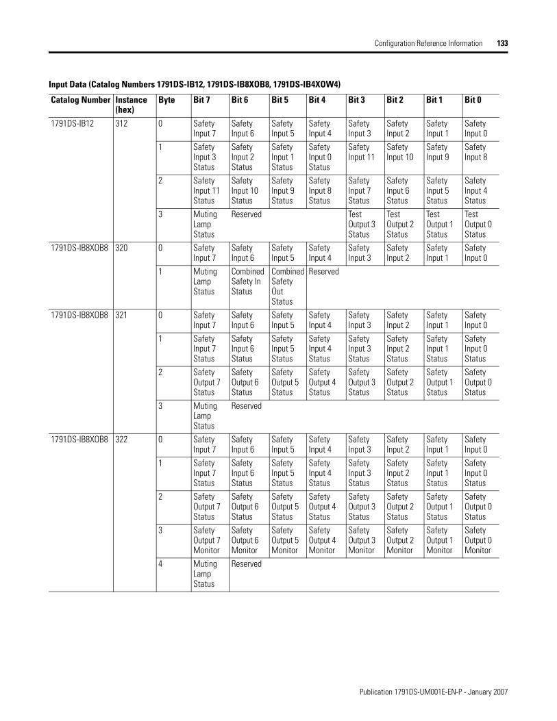
Configuration Reference Information 133
1791DS-IB12 312 0 Safety Input 7
Safety Input 6
Safety Input 5
Safety Input 4
Safety Input 3
Safety Input 2
Safety Input 1
Safety Input 0
1 Safety Input 3 Status
Safety Input 2 Status
Safety Input 1 Status
Safety Input 0 Status
Safety Input 11
Safety Input 10
Safety Input 9
Safety Input 8
2 Safety Input 11 Status
Safety Input 10 Status
Safety Input 9 Status
Safety Input 8 Status
Safety Input 7 Status
Safety Input 6 Status
Safety Input 5 Status
Safety Input 4 Status
3 Muting Lamp Status
Reserved Test Output 3 Status
Test Output 2 Status
Test Output 1 Status
Test Output 0 Status
1791DS-IB8XOB8 320 0 Safety Input 7
Safety Input 6
Safety Input 5
Safety Input 4
Safety Input 3
Safety Input 2
Safety Input 1
Safety Input 0
1 Muting Lamp Status
Combined Safety In Status
Combined Safety Out Status
Reserved
1791DS-IB8XOB8 321 0 Safety Input 7
Safety Input 6
Safety Input 5
Safety Input 4
Safety Input 3
Safety Input 2
Safety Input 1
Safety Input 0
1 Safety Input 7 Status
Safety Input 6 Status
Safety Input 5 Status
Safety Input 4 Status
Safety Input 3 Status
Safety Input 2 Status
Safety Input 1 Status
Safety Input 0 Status
2 Safety Output 7 Status
Safety Output 6 Status
Safety Output 5 Status
Safety Output 4 Status
Safety Output 3 Status
Safety Output 2 Status
Safety Output 1 Status
Safety Output 0 Status
3 Muting Lamp Status
Reserved
1791DS-IB8XOB8 322 0 Safety Input 7
Safety Input 6
Safety Input 5
Safety Input 4
Safety Input 3
Safety Input 2
Safety Input 1
Safety Input 0
1 Safety Input 7 Status
Safety Input 6 Status
Safety Input 5 Status
Safety Input 4 Status
Safety Input 3 Status
Safety Input 2 Status
Safety Input 1 Status
Safety Input 0 Status
2 Safety Output 7 Status
Safety Output 6 Status
Safety Output 5 Status
Safety Output 4 Status
Safety Output 3 Status
Safety Output 2 Status
Safety Output 1 Status
Safety Output 0 Status
3 Safety Output 7 Monitor
Safety Output 6 Monitor
Safety Output 5 Monitor
Safety Output 4 Monitor
Safety Output 3 Monitor
Safety Output 2 Monitor
Safety Output 1 Monitor
Safety Output 0 Monitor
4 Muting Lamp Status
Reserved
Input Data (Catalog Numbers 1791DS-IB12, 1791DS-IB8XOB8, 1791DS-IB4XOW4)
Catalog Number Instance (hex)
Byte Bit 7 Bit 6 Bit 5 Bit 4 Bit 3 Bit 2 Bit 1 Bit 0
Publication 1791DS-UM001E-EN-P - January 2007
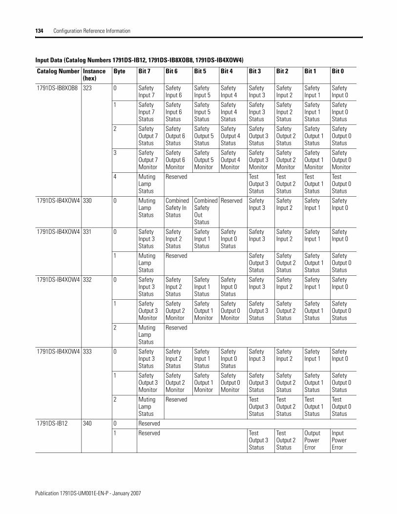
134 Configuration Reference Information
1791DS-IB8XOB8 323 0 Safety Input 7
Safety Input 6
Safety Input 5
Safety Input 4
Safety Input 3
Safety Input 2
Safety Input 1
Safety Input 0
1 Safety Input 7 Status
Safety Input 6 Status
Safety Input 5 Status
Safety Input 4 Status
Safety Input 3 Status
Safety Input 2 Status
Safety Input 1 Status
Safety Input 0 Status
2 Safety Output 7 Status
Safety Output 6 Status
Safety Output 5 Status
Safety Output 4 Status
Safety Output 3 Status
Safety Output 2 Status
Safety Output 1 Status
Safety Output 0 Status
3 Safety Output 7 Monitor
Safety Output 6 Monitor
Safety Output 5 Monitor
Safety Output 4 Monitor
Safety Output 3 Monitor
Safety Output 2 Monitor
Safety Output 1 Monitor
Safety Output 0 Monitor
4 Muting Lamp Status
Reserved Test Output 3 Status
Test Output 2 Status
Test Output 1 Status
Test Output 0 Status
1791DS-IB4XOW4 330 0 Muting Lamp Status
Combined Safety In Status
Combined Safety Out Status
Reserved Safety Input 3
Safety Input 2
Safety Input 1
Safety Input 0
1791DS-IB4XOW4 331 0 Safety Input 3 Status
Safety Input 2 Status
Safety Input 1 Status
Safety Input 0 Status
Safety Input 3
Safety Input 2
Safety Input 1
Safety Input 0
1 Muting Lamp Status
Reserved Safety Output 3 Status
Safety Output 2 Status
Safety Output 1 Status
Safety Output 0 Status
1791DS-IB4XOW4 332 0 Safety Input 3 Status
Safety Input 2 Status
Safety Input 1 Status
Safety Input 0 Status
Safety Input 3
Safety Input 2
Safety Input 1
Safety Input 0
1 Safety Output 3 Monitor
Safety Output 2 Monitor
Safety Output 1 Monitor
Safety Output 0 Monitor
Safety Output 3 Status
Safety Output 2 Status
Safety Output 1 Status
Safety Output 0 Status
2 Muting Lamp Status
Reserved
1791DS-IB4XOW4 333 0 Safety Input 3 Status
Safety Input 2 Status
Safety Input 1 Status
Safety Input 0 Status
Safety Input 3
Safety Input 2
Safety Input 1
Safety Input 0
1 Safety Output 3 Monitor
Safety Output 2 Monitor
Safety Output 1 Monitor
Safety Output 0 Monitor
Safety Output 3 Status
Safety Output 2 Status
Safety Output 1 Status
Safety Output 0 Status
2 Muting Lamp Status
Reserved Test Output 3 Status
Test Output 2 Status
Test Output 1 Status
Test Output 0 Status
1791DS-IB12 340 0 Reserved1 Reserved Test
Output 3 Status
Test Output 2 Status
Output Power Error
Input Power Error
Input Data (Catalog Numbers 1791DS-IB12, 1791DS-IB8XOB8, 1791DS-IB4XOW4)
Catalog Number Instance (hex)
Byte Bit 7 Bit 6 Bit 5 Bit 4 Bit 3 Bit 2 Bit 1 Bit 0
Publication 1791DS-UM001E-EN-P - January 2007

Configuration Reference Information 135
1791DS-IB8XOB8 341 0 Reserved1 Safety
Output 7 Monitor
Safety Output 6 Monitor
Safety Output 5 Monitor
Safety Output 4 Monitor
Safety Output 3 Monitor
Safety Output 2 Monitor
Output Power Error
Input Power Error
2 Reserved Test Output 3 Status
Test Output 2 Status
Test Output 1 Status
Test Output 0 Status
1791DS-IB4XOW4 342 0 Reserved1 Test
Output 3 Status
Test Output 2 Status
Test Output 1 Status
Test Output 0 Status
Safety Output 3 Monitor
Safety Output 2 Monitor
Safety Output 1 Monitor
Safety Output 0Monitor
Input Data (Catalog Numbers 1791DS-IB12, 1791DS-IB8XOB8, 1791DS-IB4XOW4)
Catalog Number Instance (hex)
Byte Bit 7 Bit 6 Bit 5 Bit 4 Bit 3 Bit 2 Bit 1 Bit 0
Output Data (Catalog Numbers 1791DS-IB12, 1791DS-IB8XOB8, 1791DS-IB4XOW4)
Catalog Number Instance (hex)
Byte Bit 7 Bit 6 Bit 5 Bit 4 Bit 3 Bit 2 Bit 1 Bit 0
1791DS-IB12, 1791DS-IB8XOB8, 1791DS-IB4XOW4
21 0 Reserved StandardOutput 3
StandardOutput 2
StandardOutput 1
StandardOutput 0
1791DS-IB4XOW4 233 0 Reserved Safety Output 3
Safety Output 2
Safety Output 1
Safety Output 0
1791DS-IB8XOB8 234 0 Safety Output 7
Safety Output 6
Safety Output 5
Safety Output 4
Safety Output 3
Safety Output 2
Safety Output 1
Safety Output 0
1791DS-IB4XOW4 350 0 Standard Output 3
Standard Output 2
Standard Output 1
StandardOutput 0
Safety Output 3
Safety Output 2
Safety Output 1
Safety Output 0
1791DS-IB8XOB8 351 0 Safety Output 7
Safety Output 6
Safety Output 5
Safety Output 4
Safety Output 3
Safety Output 2
Safety Output 1
SafetyOutput 0
1 Reserved StandardOutput 3
StandardOutput 2
StandardOutput 1
StandardOutput 0
Publication 1791DS-UM001E-EN-P - January 2007

136 Configuration Reference Information
1732DS-IB8, 1732DS-IB8XOBV4, 1791DS-IB8XOBV4, and 1791DS-IB16 Data
The bits in the tag definitions of RSLogix 5000 and RSNetWorx software are different than those shown in the following section. The following table defines the name associations for consistency with the programming software.
See these tables for reference data concerning input and output data.
Bit Definitions and RSLogix 5000 Tag Names
Bit Definitions RSLogix 5000 Tag NameSafety Input 0…7 Module Name:I.Pt00Data - Pt15DataSafety Input 0…7 Status Module Name:I.Pt00InputStatus - Pt15InputStatusCombined Safety In Status Module Name:I.InputStatusMuting Lamp Status Module Name:I.MutingStatus Safety Output 0…7 Module Name:O.Pt00Data - Pt07DataSafety Output 0…7 Status Module Name:I.Pt00OutputStatus - Pt07OutputStatus Combined Safety Out Status Module Name:I.OutputStatus Safety Output 0…7 Monitor Module Name:I.Pt00Readback - Pt07Readback Test Output 0…7 Data Module Name:I.Test00Data - Test07DataTest Output 0…7 Status Module Name:I.Pt00TestOutputStatus -
Pt07TestOutputStatus
Publication 1791DS-UM001E-EN-P - January 2007

Configuration Reference Information 137
Input Data (Catalog Numbers 1732DS-IB8, 1732DS-IB8XOBV4, 1791DS-IB8XOBV4, 1791DS-IB16)
Catalog Number Instance (hex)
Byte Bit 7 Bit 6 Bit 5 Bit 4 Bit 3 Bit 2 Bit 1 Bit 0
1732DS-IB8, 1732DS-IB8XOBV4,1791DS-IB8XOBV4
204 0 Safety Input 7
Safety Input 6
Safety Input 5
Safety Input 4
Safety Input 3
Safety Input 2
Safety Input 1
Safety Input 0
224 0 Safety Input 7
Safety Input 6
Safety Input 5
Safety Input 4
Safety Input 3
Safety Input 2
Safety Input 1
Safety Input 0
1 Safety Input 7Status
Safety Input 6Status
Safety Input 5Status
Safety Input 4Status
Safety Input 3Status
Safety Input 2Status
Safety Input 1Status
Safety Input 0Status
1791DS-IB16 205 0 Safety Input 7
Safety Input 6
Safety Input 5
Safety Input 4
Safety Input 3
Safety Input 2
Safety Input 1
Safety Input 0
Safety Input 15
Safety Input 14
Safety Input 13
Safety Input 12
Safety Input 11
Safety Input 10
Safety Input 9
Safety Input 8
1791DS-IB16 225 0 Safety Input 7
Safety Input 6
Safety Input 5
Safety Input 4
Safety Input 3
Safety Input 2
Safety Input 1
Safety Input 0
1 Safety Input 15
Safety Input 14
Safety Input 13
Safety Input 12
Safety Input 11
Safety Input 10
Safety Input 9
Safety Input 8
2 Safety Input 7Status
Safety Input 6Status
Safety Input 5Status
Safety Input 4Status
Safety Input 3Status
Safety Input 2Status
Safety Input 1Status
Safety Input 0Status
3 Safety Input 15 Status
Safety Input 14 Status
Safety Input 13 Status
Safety Input 12 Status
Safety Input 11 Status
Safety Input 10 Status
Safety Input 9 Status
Safety Input 8 Status
1732DS-IB8, 1791DS-IB16
300 0 Reserved Input Power Error
1732DS-IB8, 1732DS-IB8XOBV4,1791DS-IB8XOBV4
301 0 Reserved Output Power Error
Input Power Error
1732DS-IB8 314 0 Safety Input 7
Safety Input 6
Safety Input 5
Safety Input 4
Safety Input 3
Safety Input 2
Safety Input 1
Safety Input 0
1 Reserved Muting Lamp 7 Status
Muting Lamp 3 Status
1791DS-IB16 315 0 Safety Input 7
Safety Input 6
Safety Input 5
Safety Input 4
Safety Input 3
Safety Input 2
Safety Input 1
Safety Input 0
1 Safety Input 15
Safety Input 14
Safety Input 13
Safety Input 12
Safety Input 11
Safety Input 10
Safety Input 9
Safety Input 8
2 Combined Safety In Status
Reserved Reserved Reserved Muting Lamp 15Status
Muting Lamp 11 Status
Muting Lamp 7 Status
Muting Lamp 3 Status
1732DS-IB8XOBV4,1791DS-IB8XOBV4
324 0 Safety Input 7
Safety Input 6
Safety Input 5
Safety Input 4
Safety Input 3
Safety Input 2
Safety Input 1
Safety Input 0
1 Combined Safety In Status
Combined Safety Out Status
Reserved Muting Lamp 7 Status
Muting Lamp 3 Status
Publication 1791DS-UM001E-EN-P - January 2007
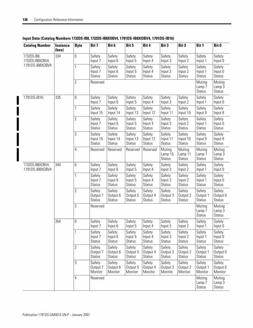
138 Configuration Reference Information
1732DS-IB8, 1732DS-IB8XOBV4,1791DS-IB8XOBV4
334 0 Safety Input 7
Safety Input 6
Safety Input 5
Safety Input 4
Safety Input 3
Safety Input 2
Safety Input 1
Safety Input 0
1 Safety Input 7Status
Safety Input 6Status
Safety Input 5Status
Safety Input 4Status
Safety Input 3Status
Safety Input 2Status
Safety Input 1Status
Safety Input 0Status
2 Reserved Muting Lamp 7 Status
Muting Lamp 3 Status
1791DS-IB16 335 0 Safety Input 7
Safety Input 6
Safety Input 5
Safety Input 4
Safety Input 3
Safety Input 2
Safety Input 1
Safety Input 0
1 Safety Input 15
Safety Input 14
Safety Input 13
Safety Input 12
Safety Input 11
Safety Input 10
Safety Input 9
Safety Input 8
2 Safety Input 7Status
Safety Input 6Status
Safety Input 5Status
Safety Input 4Status
Safety Input 3Status
Safety Input 2Status
Safety Input 1Status
Safety Input 0Status
3 Safety Input 15Status
Safety Input 14Status
Safety Input 13Status
Safety Input 12Status
Safety Input 11Status
Safety Input 10Status
Safety Input 9Status
Safety Input 8Status
4 Reserved Reserved Reserved Reserved Muting Lamp 15 Status
Muting Lamp 11 Status
Muting Lamp 7 Status
Muting Lamp 3 Status
1732DS-IB8XOBV4,1791DS-IB8XOBV4
344 0 Safety Input 7
Safety Input 6
Safety Input 5
Safety Input 4
Safety Input 3
Safety Input 2
Safety Input 1
Safety Input 0
1 Safety Input 7Status
Safety Input 6Status
Safety Input 5Status
Safety Input 4Status
Safety Input 3Status
Safety Input 2Status
Safety Input 1Status
Safety Input 0Status
2 Safety Output 7Status
Safety Output 6Status
Safety Output 5Status
Safety Output 4Status
Safety Output 3Status
Safety Output 2Status
Safety Output 1Status
Safety Output 0Status
3 Reserved Muting Lamp 7 Status
Muting Lamp 3 Status
354 0 Safety Input 7
Safety Input 6
Safety Input 5
Safety Input 4
Safety Input 3
Safety Input 2
Safety Input 1
Safety Input 0
1 Safety Input 7Status
Safety Input 6Status
Safety Input 5Status
Safety Input 4Status
Safety Input 3Status
Safety Input 2Status
Safety Input 1Status
Safety Input 0Status
2 Safety Output 7Status
Safety Output 6Status
Safety Output 5Status
Safety Output 4Status
Safety Output 3Status
Safety Output 2Status
Safety Output 1Status
Safety Output 0Status
3 Safety Output 7Monitor
Safety Output 6Monitor
Safety Output 5Monitor
Safety Output 4Monitor
Safety Output 3Monitor
Safety Output 2Monitor
Safety Output 1Monitor
Safety Output 0Monitor
4 Reserved Muting Lamp 7 Status
Muting Lamp 3 Status
Input Data (Catalog Numbers 1732DS-IB8, 1732DS-IB8XOBV4, 1791DS-IB8XOBV4, 1791DS-IB16)
Catalog Number Instance (hex)
Byte Bit 7 Bit 6 Bit 5 Bit 4 Bit 3 Bit 2 Bit 1 Bit 0
Publication 1791DS-UM001E-EN-P - January 2007

Configuration Reference Information 139
1732DS-IB8, 1732DS-IB8XOBV4,1791DS-IB8XOBV4
364 0 Safety Input 7
Safety Input 6
Safety Input 5
Safety Input 4
Safety Input 3
Safety Input 2
Safety Input 1
Safety Input 0
1 Safety Input 7Status
Safety Input 6Status
Safety Input 5Status
Safety Input 4Status
Safety Input 3Status
Safety Input 2Status
Safety Input 1Status
Safety Input 0Status
2 Test Output 7Status
Test Output 6Status
Test Output 5Status
Test Output 4Status
Test Output 3Status
Test Output 2Status
Test Output 1Status
Test Output 0Status
3 Reserved Muting Lamp 7 Status
Muting Lamp 3 Status
1791DS-IB16 365 0 Standard Output 7
Standard Output 6
Standard Output 5
Standard Output 4
Standard Output 3
Standard Output 2
Standard Output 1
Standard Output 0
1 Standard Output 15
Standard Output 14
Standard Output 13
Standard Output 12
Standard Output 11
Standard Output 10
Standard Output 9
Standard Output 8
2 Safety Input 7 Status
Safety Input 6 Status
Safety Input 5 Status
Safety Input 4 Status
Safety Input 3 Status
Safety Input 2 Status
Safety Input 1 Status
Safety Input 0 Status
3 Safety Input 15 Status
Safety Input 14 Status
Safety Input 13 Status
Safety Input 12 Status
Safety Input 11 Status
Safety Input 10 Status
Safety Input 9 Status
Safety Input 8 Status
4 Test Output 7 Status
Test Output 6 Status
Test Output 5 Status
Test Output 4 Status
Test Output 3 Status
Test Output 2 Status
Test Output 1 Status
Test Output 0 Status
5 Test Output 15 Status
Test Output 14 Status
Test Output 13 Status
Test Output 12 Status
Test Output 11 Status
Test Output 10 Status
Test Output 9 Status
Test Output 8 Status
6 Reserved Reserved Reserved Reserved Muting Lamp 15 Status
Muting Lamp 11 Status
Muting Lamp 7 Status
Muting Lamp 3 Status
1732DS-IB8XOBV4,1791DS-IB8XOBV4
374 0 Safety Input 7
Safety Input 6
Safety Input 5
Safety Input 4
Safety Input 3
Safety Input 2
Safety Input 1
Safety Input 0
1 Safety Input 7Status
Safety Input 6Status
Safety Input 5Status
Safety Input 4Status
Safety Input 3Status
Safety Input 2Status
Safety Input 1Status
Safety Input 0Status
2 Safety Output 7Status
Safety Output 6Status
Safety Output 5Status
Safety Output 4Status
Safety Output 3Status
Safety Output 2Status
Safety Output 1Status
Safety Output 0Status
3 Safety Output 7 Monitor
Safety Output 6 Monitor
Safety Output 5 Monitor
Safety Output 4 Monitor
Safety Output 3 Monitor
Safety Output 2 Monitor
Safety Output 1 Monitor
Safety Output 0 Monitor
4 Test Output 7Status
Test Output 6Status
Test Output 5Status
Test Output 4Status
Test Output 3Status
Test Output 2Status
Test Output 1Status
Test Output 0Status
5 Reserved Muting Lamp 7 Status
Muting Lamp 3 Status
Input Data (Catalog Numbers 1732DS-IB8, 1732DS-IB8XOBV4, 1791DS-IB8XOBV4, 1791DS-IB16)
Catalog Number Instance (hex)
Byte Bit 7 Bit 6 Bit 5 Bit 4 Bit 3 Bit 2 Bit 1 Bit 0
Publication 1791DS-UM001E-EN-P - January 2007

140 Configuration Reference Information
1732DS-IB8 384 0 Reserved Input Power Error
1 Test Output 7Status
Test Output 6Status
Test Output 5Status
Test Output 4Status
Test Output 3Status
Test Output 2Status
Test Output 1Status
Test Output 0Status
1791DS-IB16 385 0 Reserved Reserved Reserved Reserved Reserved Reserved Reserved Input Power Error
1 Test Output 7 Status
Test Output 6 Status
Test Output 5 Status
Test Output 4 Status
Test Output 3 Status
Test Output 2 Status
Test Output 1 Status
Test Output 0 Status
2 Test Output 15 Status
Test Output 14 Status
Test Output 13 Status
Test Output 12 Status
Test Output 11 Status
Test Output 10 Status
Test Output 9 Status
Test Output 8 Status
1732DS-IB8XOBV4,1791DS-IB8XOBV4
394 0 Reserved Output Power Error
Input Power Error
1 Test Output 7Status
Test Output 6Status
Test Output 5Status
Test Output 4Status
Test Output 3Status
Test Output 2Status
Test Output 1Status
Test Output 0Status
3A4 0 Reserved Output Power Error
Input Power Error
1 Safety Output 7 Monitor
Safety Output 6 Monitor
Safety Output 5 Monitor
Safety Output 4 Monitor
Safety Output 3 Monitor
Safety Output 2 Monitor
Safety Output 1 Monitor
Safety Output 0 Monitor
2 Test Output 7Status
Test Output 6Status
Test Output 5Status
Test Output 4Status
Test Output 3Status
Test Output 2Status
Test Output 1Status
Test Output 0Status
Input Data (Catalog Numbers 1732DS-IB8, 1732DS-IB8XOBV4, 1791DS-IB8XOBV4, 1791DS-IB16)
Catalog Number Instance (hex)
Byte Bit 7 Bit 6 Bit 5 Bit 4 Bit 3 Bit 2 Bit 1 Bit 0
Output Data (Catalog Numbers 1791DS-IB8XOBV4, 1732DS-IB8, 1732-IB8XOBV4)
Catalog Number Instance (hex)
Byte Bit 7 Bit 6 Bit 5 Bit 4 Bit 3 Bit 2 Bit 1 Bit 0
1791DS-IB8XOBV4, 1732DS-IB8, 1732-IB8XOBV4
22 0 Standard Output 7
Standard Output 6
Standard Output 5
Standard Output 4
Standard Output 3
Standard Output 2
Standard Output 1
Standard Output 0
1791DS-IB16 23 0 Standard Output 7
Standard Output 6
Standard Output 5
Standard Output 4
Standard Output 3
Standard Output 2
Standard Output 1
Standard Output 0
1 Standard Output 15
Standard Output 14
Standard Output 13
Standard Output 12
Standard Output 11
Standard Output 10
Standard Output 9
Standard Output 8
1791DS-IB8XOBV4, 1732-IB8XOBV4
234 0 Safety Output 7
Safety Output 6
Safety Output 5
Safety Output 4
Safety Output 3
Safety Output 2
Safety Output 1
Safety Output 0
1791DS-IB8XOBV4, 1732-IB8XOBV4
2C4 0 Safety Output 7
Safety Output 6
Safety Output 5
Safety Output 4
Safety Output 3
Safety Output 2
Safety Output 1
Safety Output 0
1 Standard Output 7
Standard Output 6
Standard Output 5
Standard Output 4
Standard Output 3
Standard Output 2
Standard Output 1
Standard Output 0
Publication 1791DS-UM001E-EN-P - January 2007
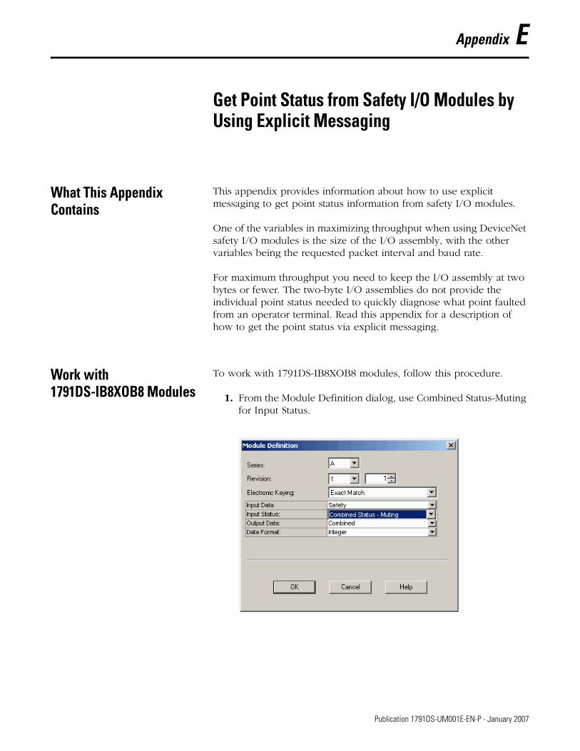
Appendix E
Get Point Status from Safety I/O Modules by Using Explicit Messaging
What This Appendix Contains
This appendix provides information about how to use explicit messaging to get point status information from safety I/O modules.
One of the variables in maximizing throughput when using DeviceNet safety I/O modules is the size of the I/O assembly, with the other variables being the requested packet interval and baud rate.
For maximum throughput you need to keep the I/O assembly at two bytes or fewer. The two-byte I/O assemblies do not provide the individual point status needed to quickly diagnose what point faulted from an operator terminal. Read this appendix for a description of how to get the point status via explicit messaging.
Work with 1791DS-IB8XOB8 Modules
To work with 1791DS-IB8XOB8 modules, follow this procedure.
1. From the Module Definition dialog, use Combined Status-Muting for Input Status.
141 Publication 1791DS-UM001E-EN-P - January 2007

142 Get Point Status from Safety I/O Modules by Using Explicit Messaging
This creates a two-byte input assembly, as shown for a module called IB8XOB8.
2. Use the combined InputStatus and combined OutputStatus bits to detect if one or more of the I/O points on the module have a fault.
• If either InputStatus or OutputStatus bit goes low (l0 = bad; 1 = good), use an explicit message to determine which individual data points have faulted.
• Use the InputStatus and OutputStatus bits to condition your msg rungs as follows.
• Note that the second rung can be used to read the status on mode transition and once a fault is detected, continue reading until the fault is corrected.
Publication 1791DS-UM001E-EN-P - January 2007

Get Point Status from Safety I/O Modules by Using Explicit Messaging 143
See the figure that shows 1791DS-IB8XOB8 message instruction parameters.
Note that we created a UDT for the destination type.
• You can find the UDT called Assembly803_1791DS_IB8XOB8 in an ACD file. This UDT is based on the Assembly803 for 1791DS_IB8XOB8 module.
• There are other assemblies in the EDS file that can be used, but this one is the most inclusive.
• Make sure the Communication Path is set to the correct module.
Publication 1791DS-UM001E-EN-P - January 2007
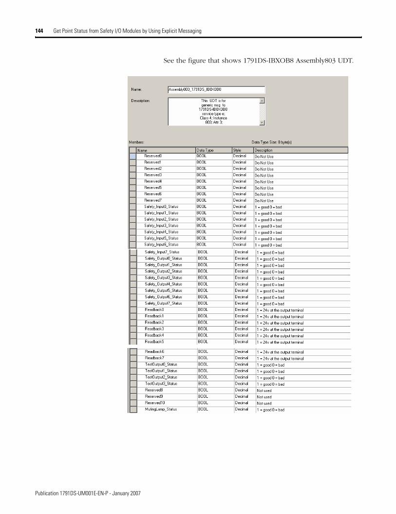
144 Get Point Status from Safety I/O Modules by Using Explicit Messaging
See the figure that shows 1791DS-IBXOB8 Assembly803 UDT.
Publication 1791DS-UM001E-EN-P - January 2007
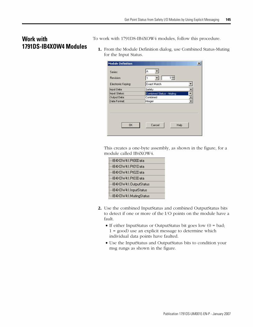
Get Point Status from Safety I/O Modules by Using Explicit Messaging 145
Work with 1791DS-IB4XOW4 Modules
To work with 1791DS-IB4XOW4 modules, follow this procedure.
1. From the Module Definition dialog, use Combined Status-Muting for the Input Status.
This creates a one-byte assembly, as shown in the figure, for a module called IB4XOW4.
2. Use the combined InputStatus and combined OutputStatus bits to detect if one or more of the I/O points on the module have a fault.
• If either InputStatus or OutputStatus bit goes low (0 = bad; 1 = good) use an explicit message to determine which individual data points have faulted.
• Use the InputStatus and OutputStatus bits to condition your msg rungs as shown in the figure.
Publication 1791DS-UM001E-EN-P - January 2007
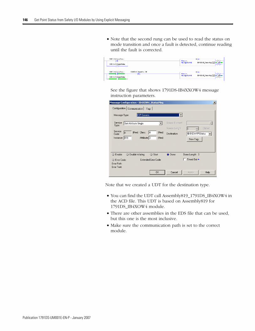
146 Get Point Status from Safety I/O Modules by Using Explicit Messaging
• Note that the second rung can be used to read the status on mode transition and once a fault is detected, continue reading until the fault is corrected.
See the figure that shows 1791DS-IB4XXOW4 message instruction parameters.
Note that we created a UDT for the destination type.
• You can find the UDT call Assembly819_1791DS_IB4XOW4 in the ACD file. This UDT is based on Assembly819 for 1791DS_IB4XOW4 module.
• There are other assemblies in the EDS file that can be used, but this one is the most inclusive.
• Make sure the communication path is set to the correct module.
Publication 1791DS-UM001E-EN-P - January 2007

Get Point Status from Safety I/O Modules by Using Explicit Messaging 147
See the figure that shows 1791DS-IB4XOW4 Assembly819 UDT.
Publication 1791DS-UM001E-EN-P - January 2007
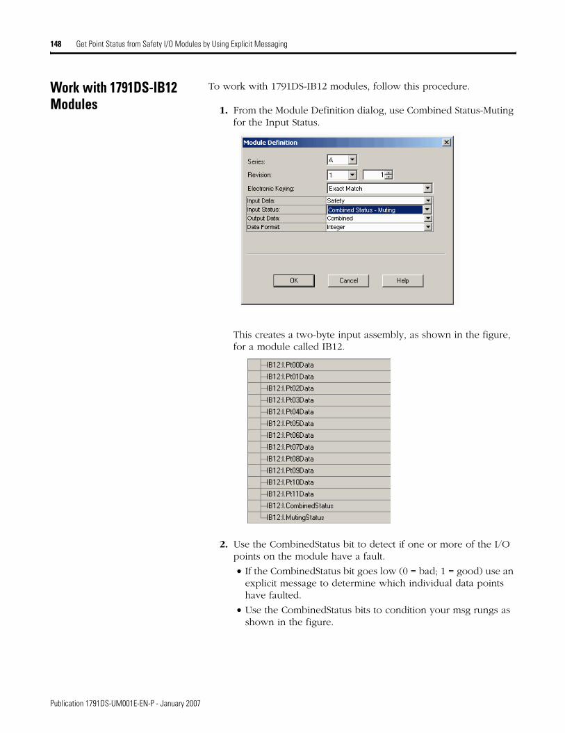
148 Get Point Status from Safety I/O Modules by Using Explicit Messaging
Work with 1791DS-IB12 Modules
To work with 1791DS-IB12 modules, follow this procedure.
1. From the Module Definition dialog, use Combined Status-Muting for the Input Status.
This creates a two-byte input assembly, as shown in the figure, for a module called IB12.
2. Use the CombinedStatus bit to detect if one or more of the I/O points on the module have a fault.
• If the CombinedStatus bit goes low (0 = bad; 1 = good) use an explicit message to determine which individual data points have faulted.
• Use the CombinedStatus bits to condition your msg rungs as shown in the figure.
Publication 1791DS-UM001E-EN-P - January 2007

Get Point Status from Safety I/O Modules by Using Explicit Messaging 149
• Note that you can use the second rung to read the status on mode transition and once a fault is detected, continue reading until the fault is corrected.
See the figure that shows 1791DS-IB12 message instruction parameters.
Note that we created a UDT for the destination type.
• You can find the UDT called Assembly786_1791DS_IB12 in the ACD file. This UDT is based on Assembly786 for the 1791DS_IB12 module.
• There are other assemblies in the EDS file that can be used but this one is the most inclusive.
• Make sure the Communication Path is set to the correct module.
Publication 1791DS-UM001E-EN-P - January 2007
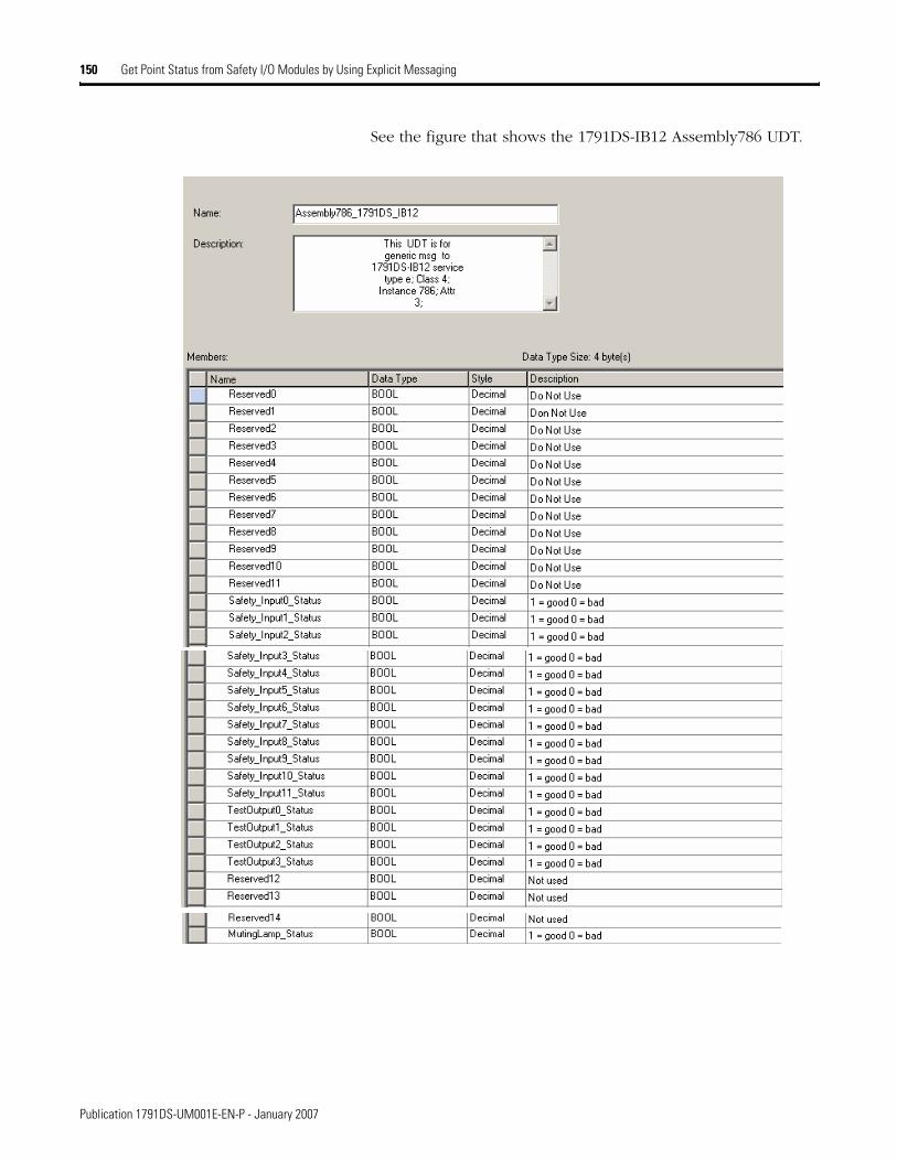
150 Get Point Status from Safety I/O Modules by Using Explicit Messaging
See the figure that shows the 1791DS-IB12 Assembly786 UDT.
Publication 1791DS-UM001E-EN-P - January 2007

Appendix F
Create SmartGuard 600 Code: An Example
What This Appendix Contains
This appendix provides sample SmartGuard application code. Read this appendix for information about how to create SmartGuard 600 code on a 1791DS-IB8XOB8 module. This code monitors a light curtain and emergency stop button to control dual safety contactors with feedback, per the following table.
1. Start RSNetWorx for DeviceNet software and open a project with a SmartGuard controller and 1791DS module, referring to Configure a SmartGuard Controller in this chapter, if needed.
SmartGuard 600 Code
Code Input/Output
Estop_chA Input 0 (pulse tested by T0)
Estop_chB Input 1 (pulse tested by T1)
LC_chA Input 2
LC_chB Input 3
Reset PB Input 4
Feedback Input 5
Contactor_A Output 0
Contactor_B Output 1
151 Publication 1791DS-UM001E-EN-P - January 2007

152 Create SmartGuard 600 Code: An Example
2. Double-click the SmartGuard controller to bring up the 1752-L24BBB dialog.
Publication 1791DS-UM001E-EN-P - January 2007
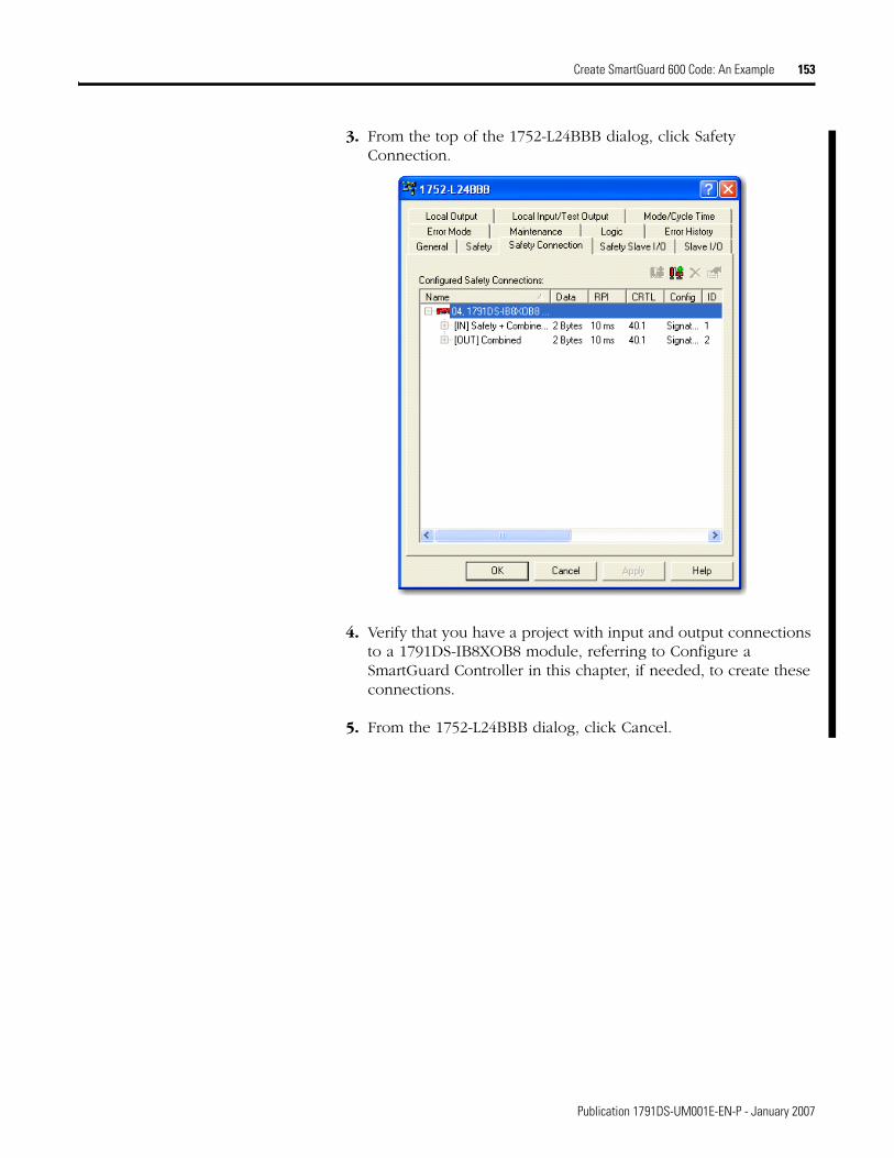
Create SmartGuard 600 Code: An Example 153
3. From the top of the 1752-L24BBB dialog, click Safety Connection.
4. Verify that you have a project with input and output connections to a 1791DS-IB8XOB8 module, referring to Configure a SmartGuard Controller in this chapter, if needed, to create these connections.
5. From the 1752-L24BBB dialog, click Cancel.
Publication 1791DS-UM001E-EN-P - January 2007

154 Create SmartGuard 600 Code: An Example
6. Double-click 1791DS module to see its properties dialog.
7. From the top of the dialog, click Safety Configuration.
8. From the dialog, perform this procedure.
Publication 1791DS-UM001E-EN-P - January 2007
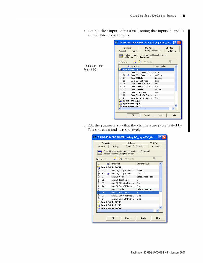
Create SmartGuard 600 Code: An Example 155
a. Double-click Input Points 00/01, noting that inputs 00 and 01 are the Estop pushbuttons.
b. Edit the parameters so that the channels are pulse tested by Test sources 0 and 1, respectively.
Double-click Input Points 00/01
Publication 1791DS-UM001E-EN-P - January 2007

156 Create SmartGuard 600 Code: An Example
c. Double-click Input Points 00/01 to minimize and Input Points 02/03 to expand, noting the following.
• The light curtain is connected to inputs 02 and 03.
• The GuardShield pulse tests OSSD1 and OSSD2, so these inputs will be configured as Safety Inputs.
Publication 1791DS-UM001E-EN-P - January 2007

Create SmartGuard 600 Code: An Example 157
d. Double-click Input Points 02/03 to minimize.
e. Double-click Input Points 04/05 to expand.
f. Add the reset button to input 04, making it a standard input as it is not required to be a safety input.
Publication 1791DS-UM001E-EN-P - January 2007
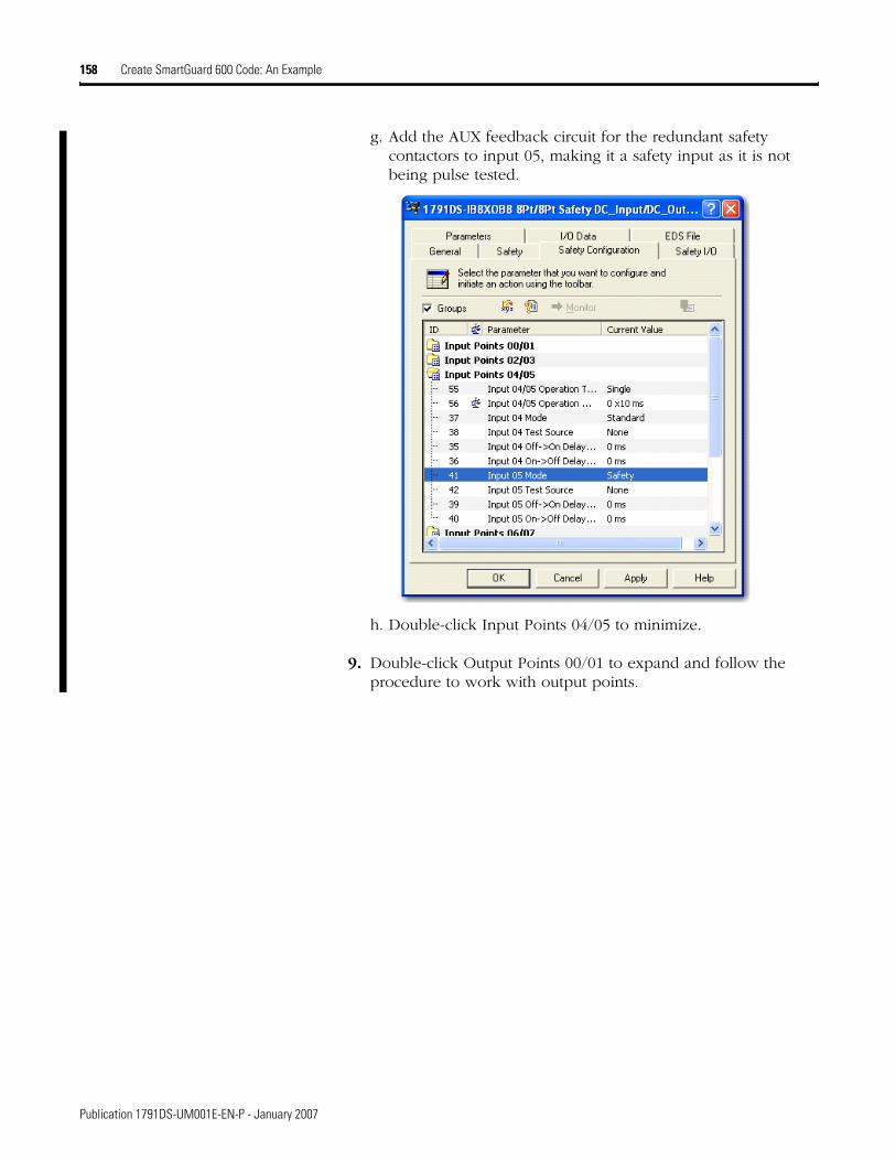
158 Create SmartGuard 600 Code: An Example
g. Add the AUX feedback circuit for the redundant safety contactors to input 05, making it a safety input as it is not being pulse tested.
h. Double-click Input Points 04/05 to minimize.
9. Double-click Output Points 00/01 to expand and follow the procedure to work with output points.
Publication 1791DS-UM001E-EN-P - January 2007
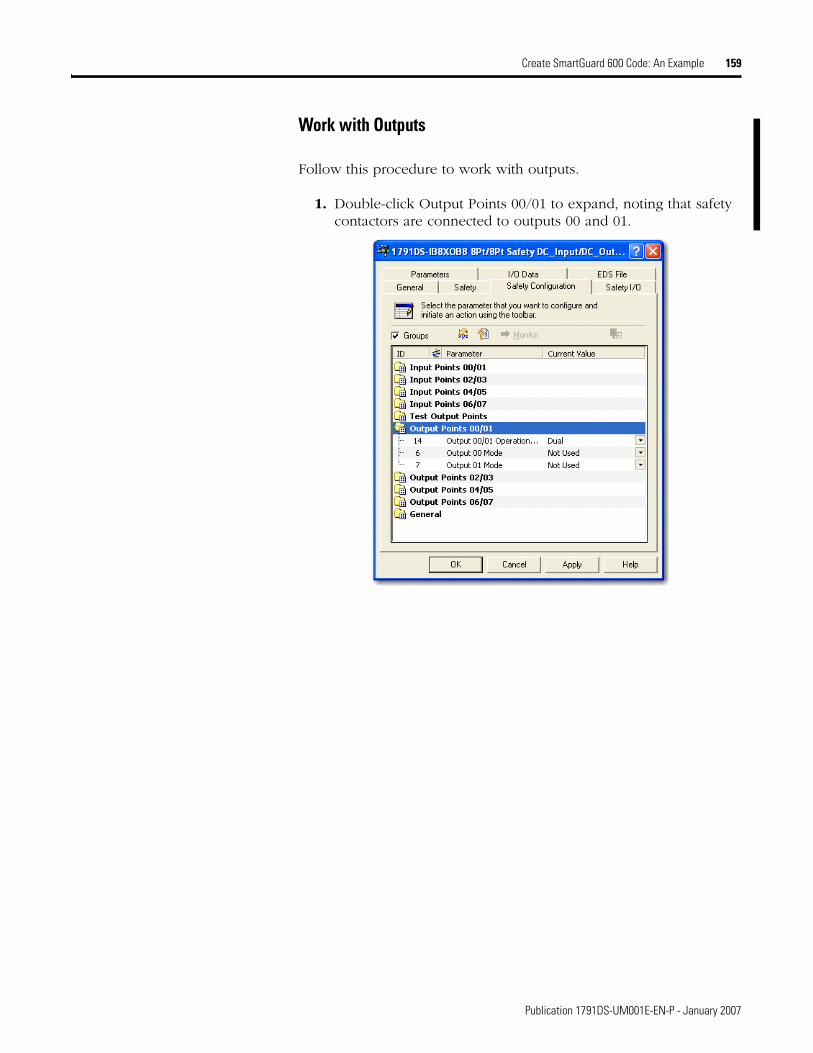
Create SmartGuard 600 Code: An Example 159
Work with Outputs
Follow this procedure to work with outputs.
1. Double-click Output Points 00/01 to expand, noting that safety contactors are connected to outputs 00 and 01.
Publication 1791DS-UM001E-EN-P - January 2007
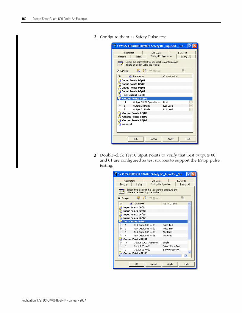
160 Create SmartGuard 600 Code: An Example
2. Configure them as Safety Pulse test.
3. Double-click Test Output Points to verify that Test outputs 00 and 01 are configured as test sources to support the EStop pulse testing.
Publication 1791DS-UM001E-EN-P - January 2007

Create SmartGuard 600 Code: An Example 161
4. Click Apply and OK to return to the main RSNetWorx for DeviceNet dialog.
5. Double-click the SmartGuard 600 icon.
Publication 1791DS-UM001E-EN-P - January 2007

162 Create SmartGuard 600 Code: An Example
6. From the top of the dialog, click Logic.
7. Click Edit to see the SmartGuard editor.
8. Drag over the EStop block and follow the procedure for working with the SmartGuard editor.
Publication 1791DS-UM001E-EN-P - January 2007

Create SmartGuard 600 Code: An Example 163
Work with the SmartGuard Editor
Use this procedure as an example of how to work with the SmartGuard editor.
1. Drag over the Estop block .
2. Click the Estop block, hold, and drag and drop onto the dialog.
3. Connect the inputs to the Estop.
4. Click Input.
Publication 1791DS-UM001E-EN-P - January 2007

164 Create SmartGuard 600 Code: An Example
5. Expand the 1791DS-IB8XOB8 module.
6. Expand the Safety Input dialog.
7. Do the same for the outputs, noting the following:
• Inputs are Pt0xData_C01.
• Outputs are Pt0xData_C02.
• C01 stands for safety connection 1.
• C02 stands for safety connection 2.
Publication 1791DS-UM001E-EN-P - January 2007
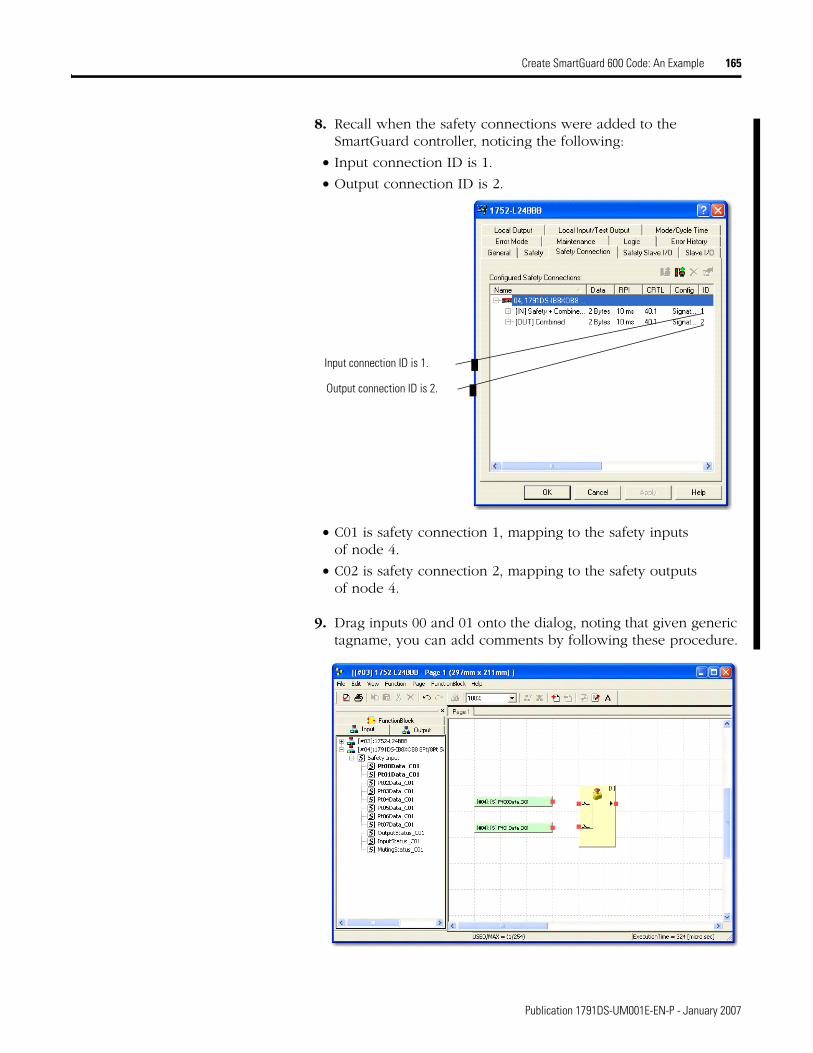
Create SmartGuard 600 Code: An Example 165
8. Recall when the safety connections were added to the SmartGuard controller, noticing the following:
• Input connection ID is 1.
• Output connection ID is 2.
• C01 is safety connection 1, mapping to the safety inputs of node 4.
• C02 is safety connection 2, mapping to the safety outputs of node 4.
9. Drag inputs 00 and 01 onto the dialog, noting that given generic tagname, you can add comments by following these procedure.
Input connection ID is 1.
Output connection ID is 2.
Publication 1791DS-UM001E-EN-P - January 2007
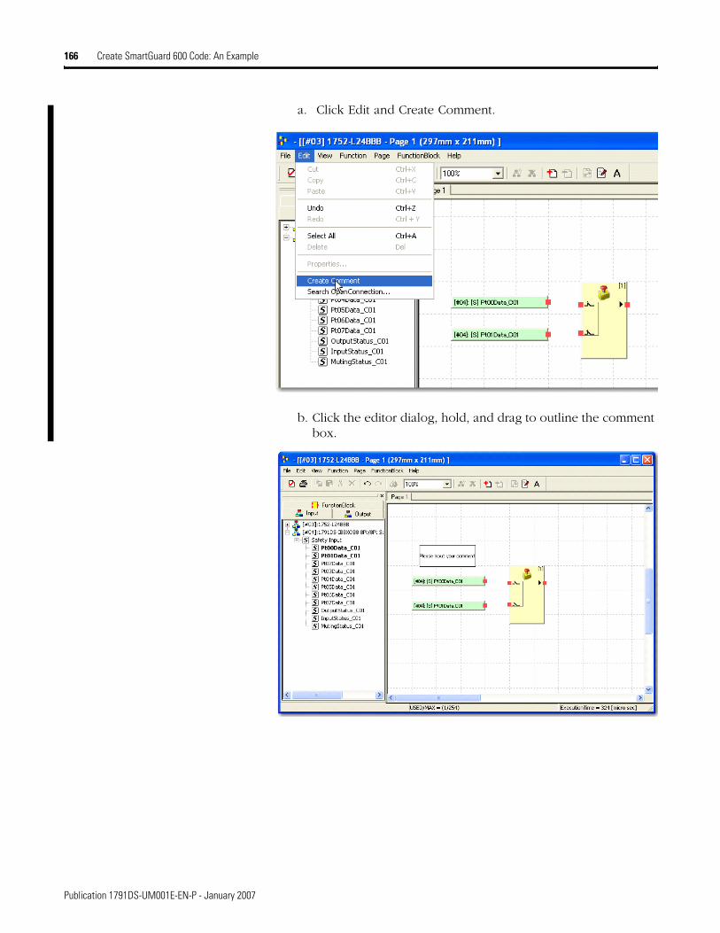
166 Create SmartGuard 600 Code: An Example
a. Click Edit and Create Comment.
b. Click the editor dialog, hold, and drag to outline the comment box.
Publication 1791DS-UM001E-EN-P - January 2007
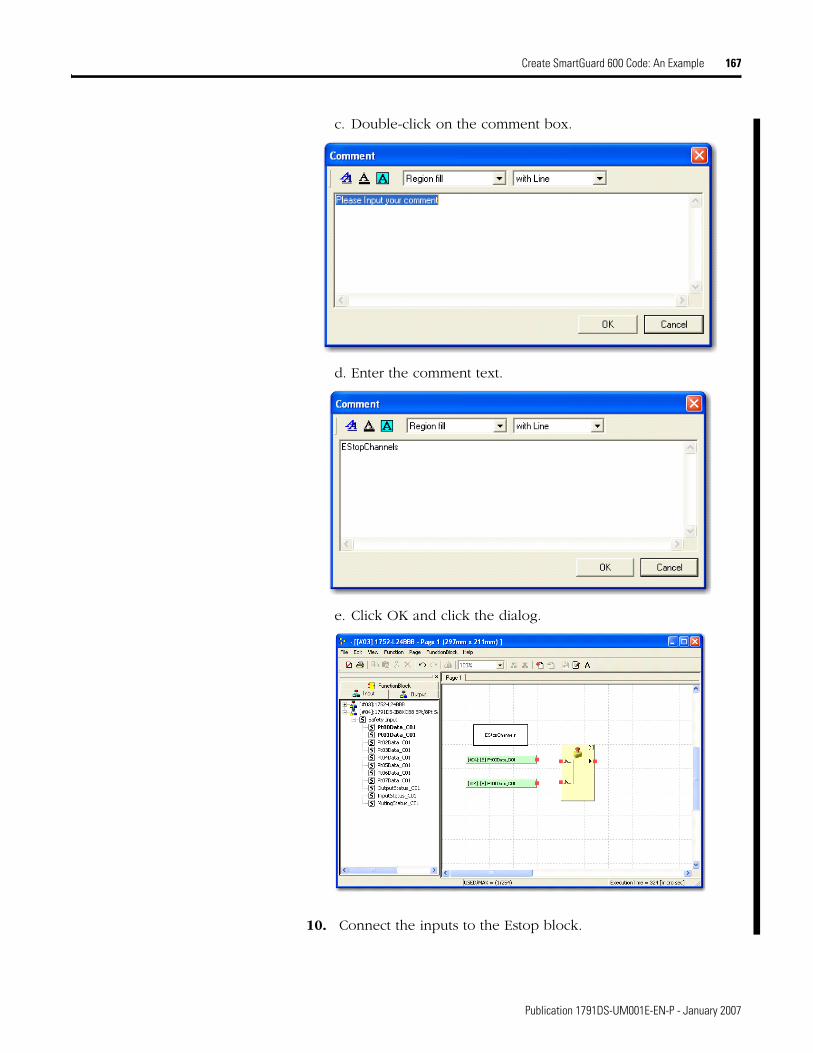
Create SmartGuard 600 Code: An Example 167
c. Double-click on the comment box.
d. Enter the comment text.
e. Click OK and click the dialog.
10. Connect the inputs to the Estop block.
Publication 1791DS-UM001E-EN-P - January 2007

168 Create SmartGuard 600 Code: An Example
a. Click on the input red blocks, drag, hold, and drop onto Estop block.
b. Click Function Block and drag a Light Curtain Mounitoring block onto the dialog.
Publication 1791DS-UM001E-EN-P - January 2007
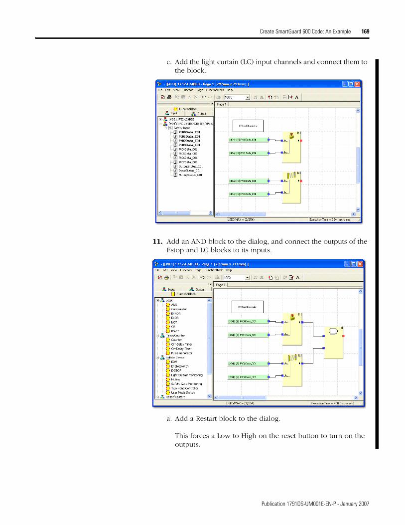
Create SmartGuard 600 Code: An Example 169
c. Add the light curtain (LC) input channels and connect them to the block.
11. Add an AND block to the dialog, and connect the outputs of the Estop and LC blocks to its inputs.
a. Add a Restart block to the dialog.
This forces a Low to High on the reset button to turn on the outputs.
Publication 1791DS-UM001E-EN-P - January 2007
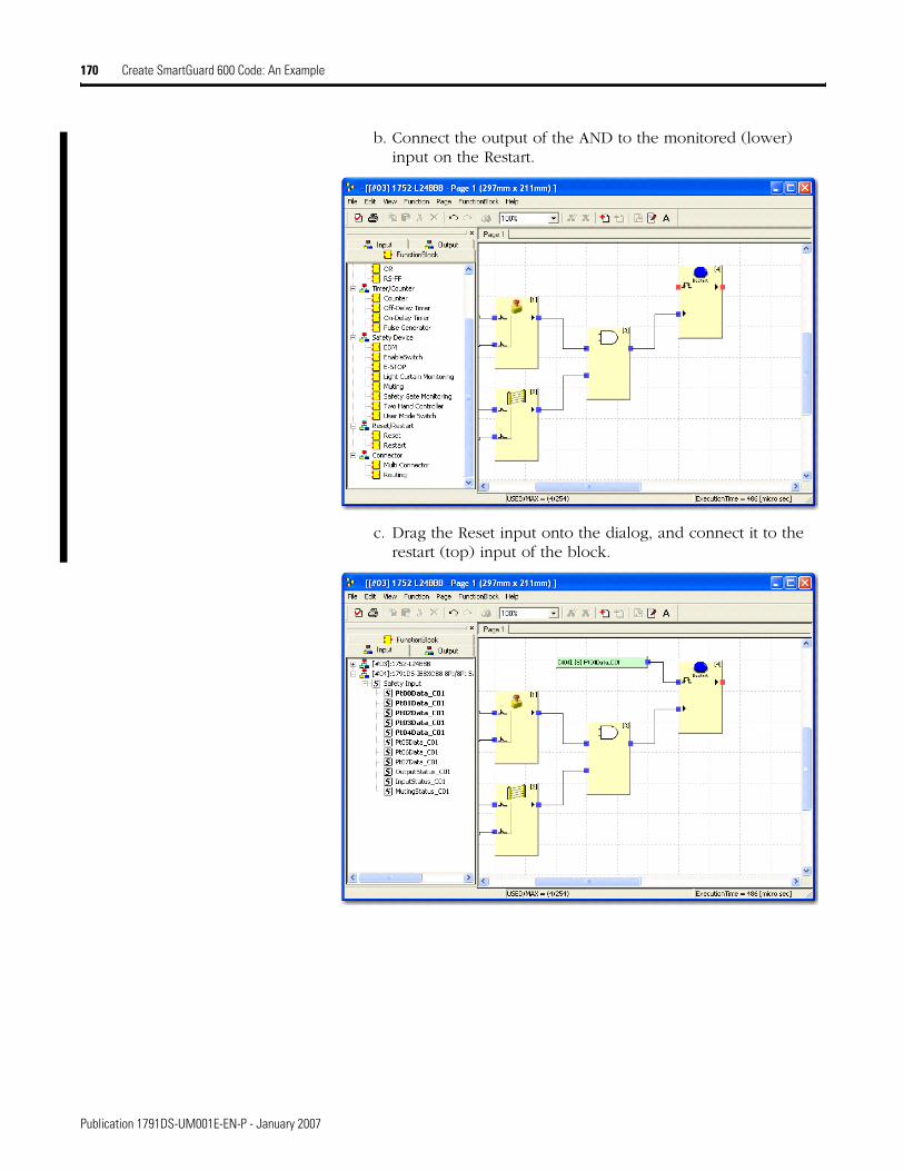
170 Create SmartGuard 600 Code: An Example
b. Connect the output of the AND to the monitored (lower) input on the Restart.
c. Drag the Reset input onto the dialog, and connect it to the restart (top) input of the block.
Publication 1791DS-UM001E-EN-P - January 2007
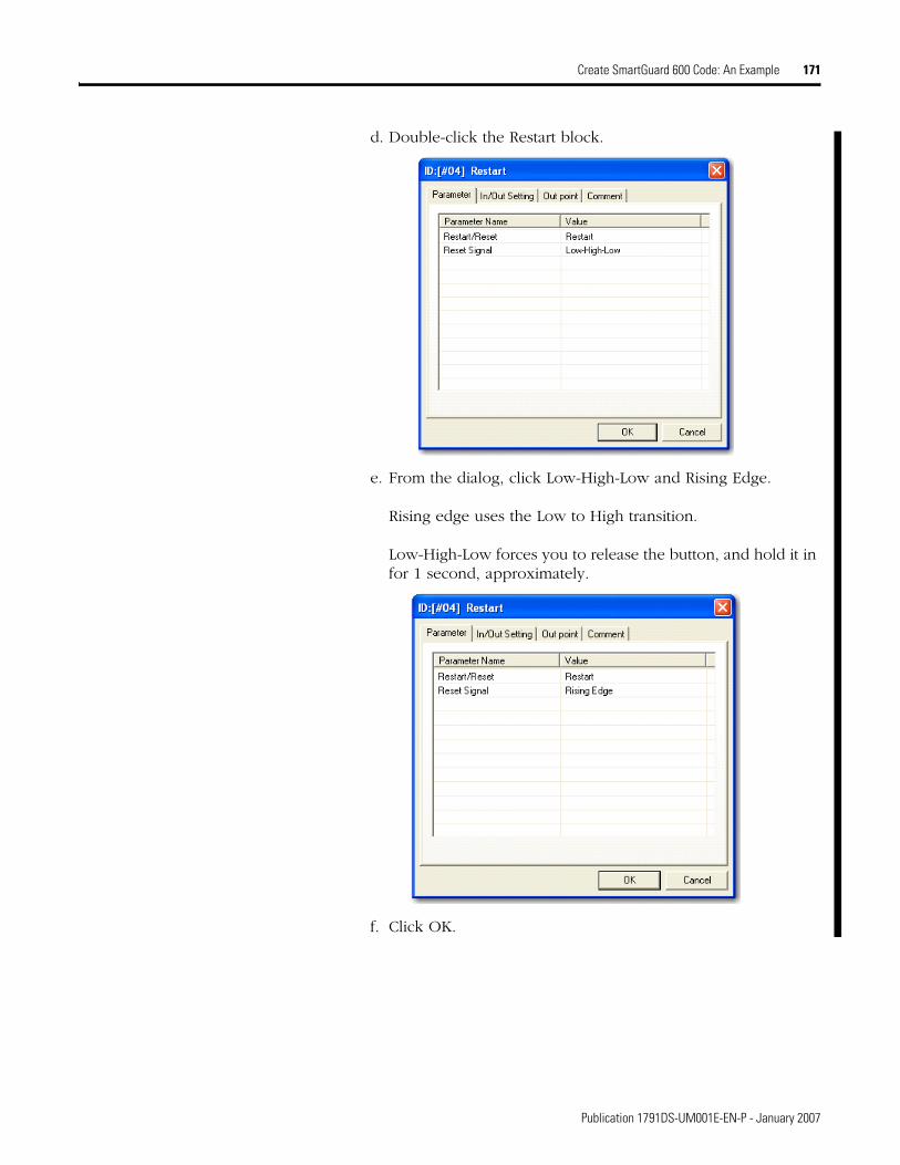
Create SmartGuard 600 Code: An Example 171
d. Double-click the Restart block.
e. From the dialog, click Low-High-Low and Rising Edge.
Rising edge uses the Low to High transition.
Low-High-Low forces you to release the button, and hold it in for 1 second, approximately.
f. Click OK.
Publication 1791DS-UM001E-EN-P - January 2007
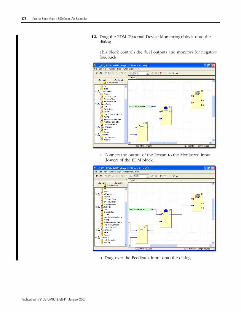
172 Create SmartGuard 600 Code: An Example
12. Drag the EDM (External Device Monitoring) block onto the dialog.
This block controls the dual outputs and monitors for negative feedback.
a. Connect the output of the Restart to the Monitored input (lower) of the EDM block.
b. Drag over the Feedback input onto the dialog.
Publication 1791DS-UM001E-EN-P - January 2007

Create SmartGuard 600 Code: An Example 173
c. Connect it to the EDM FEEDBACK input (top) of the EDM block.
d. Drag the Contactor Outputs onto the dialog, noting they are on the Output dialog under Safety Output under the 1752-L24BBB module.
e. Connect them to the outputs of the EDM block.
Click Apply.
Publication 1791DS-UM001E-EN-P - January 2007

174 Create SmartGuard 600 Code: An Example
f. Click Apply to see the LogicEditor Tool dialog.
g. From the LogicEditor Tool dialog, click OK.
13. Close the editor.
14. From the SmartGuard dialog, click Apply and OK.
15. If online, your program downloads; if offline, you need to download to the SmartGuard controller.
Close the editor.
Publication 1791DS-UM001E-EN-P - January 2007

Create SmartGuard 600 Code: An Example 175
Putting the SmartGuard 600 into Run Mode
Read this to see how to place the SmartGuard 600 controller into Run mode.
1. From the main RSNetWorx for DeviceNet online node dialog, double-click the SmartGuard 600 icon to see the 1752-L24BBB dialog.
2. From the 1752-L24BBB dialog, click Mode/Cycle Time.
Publication 1791DS-UM001E-EN-P - January 2007

176 Create SmartGuard 600 Code: An Example
3. From the 1752-L24BBB dialog that appears, click Change Mode.
4. From the Change Mode dialog that appears, click Execute and OK.
The MS and NS LED indicators on both the SmartGuard 600 and Guard I/O module are now solid green. The SmartGuard 600 controller is now in Run mode and is controlling the Guard I/O module.
Publication 1791DS-UM001E-EN-P - January 2007
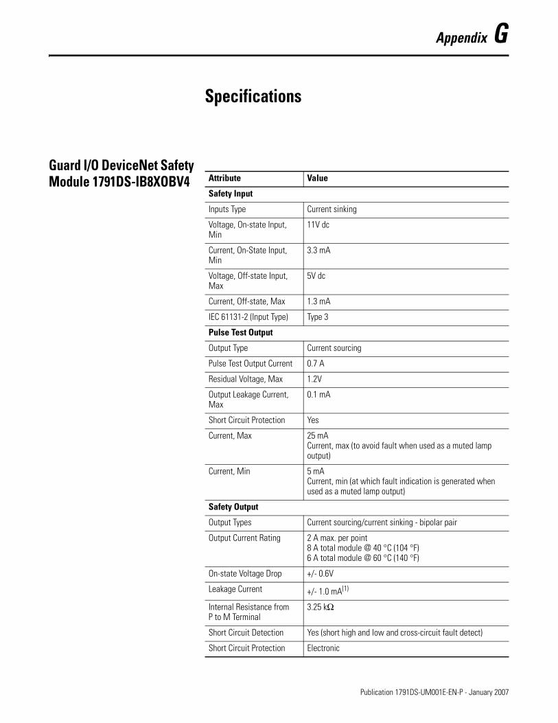
Appendix G
Specifications
Guard I/O DeviceNet Safety Module 1791DS-IB8XOBV4
Attribute Value
Safety Input
Inputs Type Current sinking
Voltage, On-state Input, Min
11V dc
Current, On-State Input, Min
3.3 mA
Voltage, Off-state Input, Max
5V dc
Current, Off-state, Max 1.3 mA
IEC 61131-2 (Input Type) Type 3
Pulse Test Output
Output Type Current sourcing
Pulse Test Output Current 0.7 A
Residual Voltage, Max 1.2V
Output Leakage Current, Max
0.1 mA
Short Circuit Protection Yes
Current, Max 25 mACurrent, max (to avoid fault when used as a muted lamp output)
Current, Min 5 mACurrent, min (at which fault indication is generated when used as a muted lamp output)
Safety Output
Output Types Current sourcing/current sinking - bipolar pair
Output Current Rating 2 A max. per point8 A total module @ 40 °C (104 °F)6 A total module @ 60 °C (140 °F)
On-state Voltage Drop +/- 0.6V
Leakage Current +/- 1.0 mA(1)
Internal Resistance from P to M Terminal
3.25 kΩ
Short Circuit Detection Yes (short high and low and cross-circuit fault detect)
Short Circuit Protection Electronic
177 Publication 1791DS-UM001E-EN-P - January 2007
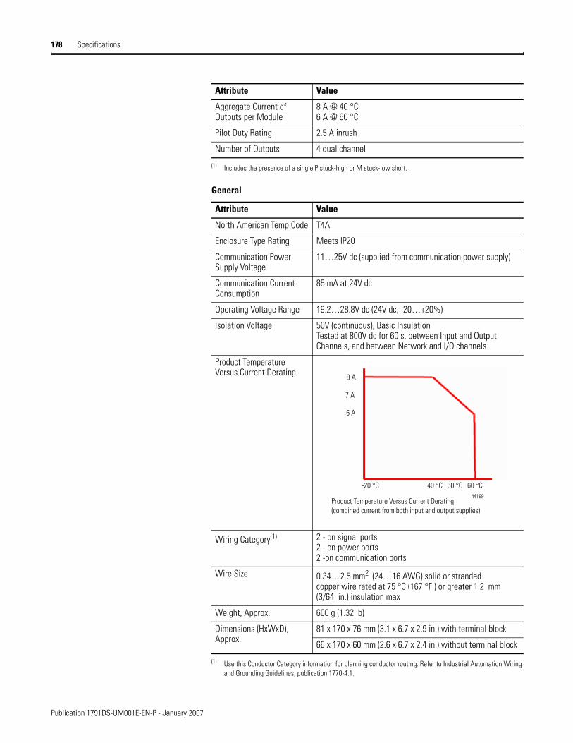
178 Specifications
Aggregate Current of Outputs per Module
8 A @ 40 °C6 A @ 60 °C
Pilot Duty Rating 2.5 A inrush
Number of Outputs 4 dual channel
(1) Includes the presence of a single P stuck-high or M stuck-low short.
General
Attribute Value
North American Temp Code T4A
Enclosure Type Rating Meets IP20
Communication Power Supply Voltage
11…25V dc (supplied from communication power supply)
Communication Current Consumption
85 mA at 24V dc
Operating Voltage Range 19.2…28.8V dc (24V dc, -20…+20%)
Isolation Voltage 50V (continuous), Basic InsulationTested at 800V dc for 60 s, between Input and Output Channels, and between Network and I/O channels
Product Temperature Versus Current Derating
Wiring Category(1) 2 - on signal ports2 - on power ports2 -on communication ports
Wire Size 0.34…2.5 mm2 (24…16 AWG) solid or stranded copper wire rated at 75 °C (167 °F ) or greater 1.2 mm (3/64 in.) insulation max
Weight, Approx. 600 g (1.32 lb)
Dimensions (HxWxD), Approx.
81 x 170 x 76 mm (3.1 x 6.7 x 2.9 in.) with terminal block
66 x 170 x 60 mm (2.6 x 6.7 x 2.4 in.) without terminal block
(1) Use this Conductor Category information for planning conductor routing. Refer to Industrial Automation Wiring and Grounding Guidelines, publication 1770-4.1.
Attribute Value
8 A
7 A
6 A
-20 °C 40 °C 50 °C 60 °C
Product Temperature Versus Current Derating (combined current from both input and output supplies)
44199
Publication 1791DS-UM001E-EN-P - January 2007

Specifications 179
Environmental Specifications
Attribute Value
Temperature, operating IEC 60068-2-1 (Test Ad, Operating Cold),IEC 60068-2-2 (Test Bd, Operating Dry Heat),IEC 60068-2-14 (Test Nb, Operating Thermal Shock):-20…60 °C (-4…140 °F)
Temperature, storage IEC 60068-2-1 (Test Ab, Unpackaged Nonoperating Cold),IEC 60068-2-2 (Test Bb, Unpackaged Nonoperating Dry Heat),IEC 60068-2-14 (Test Na, Unpackaged Nonoperating Thermal Shock):-40…85 °C (-40…185 °F)
Relative Humidity IEC 60068-2-30 (Test Db, Unpackaged Nonoperating Damp Heat):5…95% noncondensing
Vibration IEC 60068-2-6 (Test Fc, Operating):5 g at 10…500 Hz
Shock, Operating IEC 60068-2-27 (Test Ea, Unpackaged Shock): 30 g
Shock, Nonoperating IEC 60068-2-27 (Test Ea, Unpackaged Shock): 50 g
Emissions CISPR 11: Group 1, Class A
ESD Immunity IEC 61000-4-2:8 kV contact discharges15 kV air discharges
Radiated RF Immunity IEC 61000-4-3:10V/m with 1 kHz sine-wave 80%AM from 80 MHz…2000 MHz10V/m with 200 Hz 50% Pulse 100%AM at 900 MHz10V/m with 200 Hz 50% Pulse 100%AM at 1890 MHz1V/m with 1 kHz sine-wave 80%AM from 2000…2700 MHz
Conducted RF Immunity IEC 61000-4-6: 10V rms with 1 kHz sine-wave 80%AM from 150 kHz…80 MHz
EFT/B Immunity IEC 61000-4-4:±2 kV at 5 kHz on power ports±2 kV at 5 kHz on signal ports±2 kV at 5 kHz on communication\ ports
Surge Transient Immunity IEC 61000-4-5:±1 kV line-line (DM) and ±2 kV line-earth (CM) on power ports±1 kV line-line (DM) and ±2 kV line-earth (CM) on signal ports±2 kV line-earth (CM) on communication ports
Publication 1791DS-UM001E-EN-P - January 2007
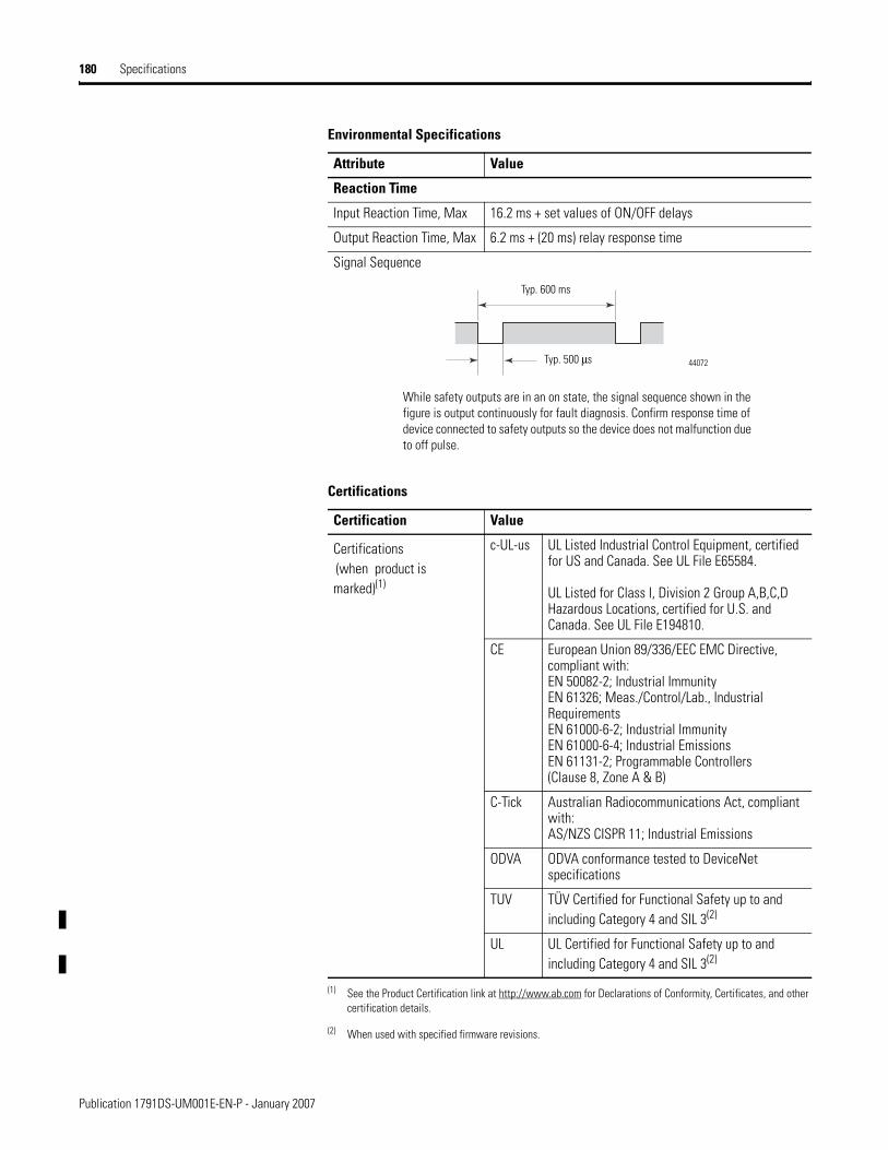
180 Specifications
Reaction Time
Input Reaction Time, Max 16.2 ms + set values of ON/OFF delays
Output Reaction Time, Max 6.2 ms + (20 ms) relay response time
Signal Sequence
Certifications
Certification Value
Certifications
(when product is marked)(1)
c-UL-us UL Listed Industrial Control Equipment, certified for US and Canada. See UL File E65584.
UL Listed for Class I, Division 2 Group A,B,C,D Hazardous Locations, certified for U.S. and Canada. See UL File E194810.
CE European Union 89/336/EEC EMC Directive, compliant with:EN 50082-2; Industrial ImmunityEN 61326; Meas./Control/Lab., Industrial RequirementsEN 61000-6-2; Industrial ImmunityEN 61000-6-4; Industrial EmissionsEN 61131-2; Programmable Controllers (Clause 8, Zone A & B)
C-Tick Australian Radiocommunications Act, compliant with:AS/NZS CISPR 11; Industrial Emissions
ODVA ODVA conformance tested to DeviceNet specifications
TUV TÜV Certified for Functional Safety up to and including Category 4 and SIL 3(2)
UL UL Certified for Functional Safety up to and including Category 4 and SIL 3(2)
(1) See the Product Certification link at http://www.ab.com for Declarations of Conformity, Certificates, and other certification details.
(2) When used with specified firmware revisions.
Environmental Specifications
Attribute Value
Typ. 600 ms
44072
While safety outputs are in an on state, the signal sequence shown in the figure is output continuously for fault diagnosis. Confirm response time of device connected to safety outputs so the device does not malfunction due to off pulse.
Typ. 500 μs
Publication 1791DS-UM001E-EN-P - January 2007

Specifications 181
Guard I/O DeviceNet Safety Module 1791DS-IB12, 1791DS-IB8XOB8, 1791DS-IB4XOW4
I/O Connectors
Attribute Value
Wire type CopperUse the following to wire 1791DS.
• 0.2…2.5 mm2 (AWG 24…12)Solid wire
• 0.34…1.5 mm2 (AWG 22…16 )Standard (flexible) wire with insulation-covered bar terminal
Environmental Specifications
Attribute Value
Communications power supply voltage
11…25V dc (supplied from communications power supply)
Communications current consumption
110 mA at 24V dc
I/O power supply voltage 20.4…26.4V dc (24V dc, -15…+10%)
Operational temperature -10…55 °C (14…131 °F)
Storage temperature -40…70 °C (-40…158 °F)
Relative humidity 10…95% non-condensing (1791DS-IB12,-IB8XOB8) 10…85% non-condensing (1791DS-IB4XOW4)
Vibration 0.35 mm (0.01 in.) at 10…57 Hz5 g at 57…150 Hz
Operating shock 15 g (1791DS-IB12, 1791-IB8XOB8)10 g (1791DS-IB4XOW4)
Operating environment No corrosive gases
Overvoltage category II (per IEC 61131-2:4.4.2)
Weight 420 g (0.93 lb) - 1791DS-IB12, 1791-IB8XOB8 600 g (1.32 lb) - 1791DS-IB4XOW4
Enclosure Type Rating None (open-style)
Wiring Category(1)
(1) Use this Conductor Category information for planning conductor routing. Refer to Industrial Automation Wiring and Grounding Guidelines, publication 1770-4.1.
2 - on signal ports2 - on power ports2 -on communications ports
Safety Input Specifications
Attribute Value
Inputs type Current sinking
ON voltage 11V dc min
Publication 1791DS-UM001E-EN-P - January 2007

182 Specifications
OFF voltage 5V dc max
OFF current 1 mA max
Input current 6 mA
Test Output Specifications
Attribute Value
Output type Current sourcing
Rated output current 0.7 A
Residual voltage 1.2V max
Leakage current 0.1 mA max
Safety Output Specifications
Attribute Value
Output type Current sourcing
Rated output current 0.5 A
Residual voltage 1.2V max
Leakage current 0.1 mA max
Signal Sequence(1)
(1) While safety outputs are in an on state, the signal sequence shown in the figure is output continuously for fault diagnosis. Confirm response time of device connected to safety outputs so the device does not malfunction due to this off pulse.
Safety Output (Relay) Specifications
Attribute Value
Relay type G7SA-2A2B EN50205 Class A
Minimum permissible load 5V dc, 1mA
Resistive load 240V ac 2A 30V dc 2A
Inductive load 240V ac 2A (cos Θ = 0.3) 24V dc 1A
Durability (mechanical) 5,000,000 operations min (at approximately 7,200 operations/hr)
Durability (electrical) 100,000 operations min at approximately 1,800 operations/hr)
Safety Input Specifications
Typ. 700 μs
Typ. 648 ms
Publication 1791DS-UM001E-EN-P - January 2007

Specifications 183
Reaction Time
Attribute Value
Max input reaction time 16.2 ms + set values of on/off delays
Max output reaction time 6.2 ms + (20 ms) relay response time, 1791DS-IB4XOW4 only
Certification Value
Certifications
(when product is marked)(1)
c-UL-us UL Listed Industrial Control Equipment, certified for US and Canada (all models).
UL Listed for Class I, Division 2, Group A,B,C,D Hazardous Locations, certified for U.S. and Canada (1791DS-IB12 and 1791DS-IB8XOB8).
CE European Union 89/336/EEC EMC Directive, compliant with:EN 61000-6-2; Industrial ImmunityEN 61000-6-4; Industrial EmissionsEN 61131-2; Programmable Controllers (Clause 8, Zone A & B)European Union 73/23/EEC LVD Directive, compliant with"EN 61131-2; Programmable Controllers (Clause 11) (1791DS-IB4XOW4)
C-Tick Australian Radiocommunications Act, compliant with:AS/NZS CISPR 11; Industrial Emissions
ODVA ODVA tested to DeviceNet specifications
TUV Functional Safety, Compliant with IEC 61508 (SIL3) and EN 954-1 (Category 4)
UL UL Certified for Functional Safety
(1) See the Product Certification link at http://www.ab.com for Declarations of Conformity, Certificates, and other certification details.
Publication 1791DS-UM001E-EN-P - January 2007

184 Specifications
Notes:
Publication 1791DS-UM001E-EN-P - January 2007
Index
Aabout catalog numbers 13administrator
safety 7architectures
safety 14
Bbus off 6
Ccable, USB 62cables 37catalog numbers 13cleaning 106colored stickers 39configuration lock 20configure the module 41connecting
communications connectors 39controller, SmartGuard 62controlling devices 30
Ddialog
General 44Input Configuration 54Output Configuration 58Safety 51Test Output Configuration 57
DIN rail 11directives 32drivers, USB 61
EEC directives 11editor, SmartGuard 163electronic data sheet 6EMC directives 33explicit messages 103, 109, 141
F
ferrite core 34Found New Hardware Wizard 62
Gget point status information from safety
I/O modules 141
Hhelp button 41
II/O configuration tree 41indicators
LED 97module 97
input configuration dialog 54inspection 107installation 36
Llegislation and standards 31
Mmaintenance interval
for relay contacts 107mean time between failure 6, 113model types 13module properties dialog 44mounting 11MTBF
See mean time between failure.
Nnode address setting 40noise 34
OODVA 6, 31off-delay function 26on-delay function 26output configuration dialog 58
Publication 1791DS-UM001E-EN-P - January 2007

2 Index
PPFD
See probability of failure on demand.PFH
See probability of failure per hour.precautions for use 8probability of failure on demand 6, 113probability of failure per hour 6, 113publications, related 5
Rrelated publications 5remote I/O allocations 121replace units 108RSLogix 5000 software 41RSNetworx for DeviceNet software 61
Ssafety dialog 51safety functions
safety input 20safety output 27
safety network number 6, 44
SmartGuardcode example 151controller 61editor 163
SNNSee safety network number.
standards 32stickers
on communications connectors 39
Ttest output configuration dialog 57troubleshoot 103
UUniversal Serial Bus 61
Vventilation 11
Wwho should use this manual 5wiring examples 97
Publication 1791DS-UM001E-EN-P - January 2007

How Are We Doing?Your comments on our technical publications will help us serve you better in the future.Thank you for taking the time to provide us feedback.You can complete this form and mail (or fax) it back to us or email us at [email protected]
Please complete the sections below. Where applicable, rank the feature (1=needs improvement, 2=satisfactory, and 3=outstanding).Pub. Title/Type Guard I/O DeviceNet Safety Modules
Cat. No. 1732DS-IB8, 1732DS-IB8XOBV4, 1791DS-IB12, 1791DS-IB8XOB8, 1791DS-IB4XOW4, 1791DS-IB8XOBV4, 1791DS-IB16
Pub. No. 1791DS-UM001E-EN-P Pub. Date January 2007 Part No. 953157-09
Overall Usefulness 1 2 3 How can we make this publication more useful for you?
Completeness(all necessary information
is provided)
1 2 3 Can we add more information to help you?
procedure/step illustration feature
example guideline other
explanation definition
Technical Accuracy(all provided information
is correct)
1 2 3 Can we be more accurate?
text illustration
Clarity(all provided information is
easy to understand)
1 2 3 How can we make things clearer?
Other Comments You can add additional comments on the back of this form.
Your Name
Your Title/Function Would you like us to contact you regarding your comments?
Location/Phone ___No, there is no need to contact me
___Yes, please call me
___Yes, please email me at _______________________
___Yes, please contact me via _____________________
Return this form to: Rockwell Automation Technical Communications, 1 Allen-Bradley Dr., Mayfield Hts., OH 44124-9705
Fax: 440-646-3525 Email: [email protected]
Publication CIG-CO521C-EN-P- May 2003 957782-91

Other Comments
PLEASE FOLD HERE
NO POSTAGE NECESSARY IF MAILED
IN THE UNITED STATES
BUSINESS REPLY MAILFIRST-CLASS MAIL PERMIT NO. 18235 CLEVELAND OH
POSTAGE WILL BE PAID BY THE ADDRESSEE
1 ALLEN-BRADLEY DRMAYFIELD HEIGHTS OH 44124-9705
PLEASE FASTEN HERE (DO NOT STAPLE)
PLEA
SE R
EMOV
E


Publication 1791DS-UM001E-EN-P - January 2007 jjjj j953157-09Supersedes Publication 1791DS-UM001D-EN-P - November 2006 Copyright © 2007 Rockwell Automation, Inc. All rights reserved. Printed in the U.S.A.
Rockwell Automation Support
Rockwell Automation provides technical information on the Web to assist you in using its products. At http://support.rockwellautomation.com, you can find technical manuals, a knowledge base of FAQs, technical and application notes, sample code and links to software service packs, and a MySupport feature that you can customize to make the best use of these tools.
For an additional level of technical phone support for installation, configuration, and troubleshooting, we offer TechConnect Support programs. For more information, contact your local distributor or Rockwell Automation representative, or visit http://support.rockwellautomation.com.
Installation Assistance
If you experience a problem with a hardware module within the first 24 hours of installation, please review the information that's contained in this manual. You can also contact a special Customer Support number for initial help in getting your module up and running.
New Product Satisfaction Return
Rockwell tests all of its products to ensure that they are fully operational when shipped from the manufacturing facility. However, if your product is not functioning, it may need to be returned.
United States 1.440.646.3223Monday – Friday, 8am – 5pm EST
Outside United States
Please contact your local Rockwell Automation representative for any technical support issues.
United States Contact your distributor. You must provide a Customer Support case number (see phone number above to obtain one) to your distributor in order to complete the return process.
Outside United States
Please contact your local Rockwell Automation representative for return procedure.