Embed Size (px)
Citation preview

Model 17800B Recovery/Recycling/Recharging Unit 1
OperatingManual
Model 17800B/17801BRecovery/Recycling/Recharging UnitFor Multiple Refrigerants

© 2001 Robinair, SPX Corporation2
80S2
WARNINGPRESSURIZED TANK CONTAINS LIQUID REFRIGERANT. OVERFILLING OF THE TANK MAY CAUSE VIOLENT EXPLOSIONAND POSSIBLE INJURY OR DEATH. Safety devices requires the use of only authorized refillable refrigerant tanks. This includesRobinair Part Numbers 17506 and 34750 (50lb.) tank. Do not recover refrigerants into a non-refillable storage container! Federal regulationsrequire refrigerant to be transported only in containers meeting DOT spec. 4BW or DOT spec. 4BA.
ALL HOSES MAY CONTAIN LIQUID REFRIGERANT UNDER PRESSURE. Contact with refrigerant may cause injury. Wear properprotective equipment, including safety goggles. Disconnect hoses with extreme caution.
HIGH VOLTAGE ELECTRICITY INSIDE PANELS. RISK OF ELECTRICAL SHOCK. Disconnect power before servicing unit. Refer
to the operating manual.
TO REDUCE THE RISK OF FIRE, avoid the use of an extension cord because theextension cord may overheat. However, if you must use an extension cord, the cord shall be No. 14 AWG minimum and keep the cord asshort as possible. Do not use this equipment in the vicinity of spilled or open containers of gasoline or other flammable substances.
Use this equipment in locations with mechanical ventilation that provides at least four air changes per hour or locate the equipment at least18 inches off the floor.
Make certain that all safety devices are functioning properly before operating the unit. Before operating, read and follow the instructions andwarnings in the operating manual.
CAUTION: RISK OF INJURY. THIS EQUIPMENT SHOULD ONLY BE OPERATED BY CERTIFIED PERSONNEL. Operator mustbe familiar with A/C systems, refrigerants and the dangers of pressurized components.
Use this unit only with R-12, R-134a, and ARI 98 Refrigerant Classes III and IV systems only. This unit is not designed forany other purpose than recovering or recycling refrigerants! Do not mix refrigerant types!
Additional health and safety information may be obtained from refrigerant and lubricant manufacturers.
ATTENTION!Ce réservoir sous pression contient du frigorigène liquide. S’il est surchargé, ce réservoir peut exploser et causer des blessures ou lamort.ATTENTION. Débrancher avant la maintenance.ATTENTION. Pour réduire les risques d’incendie, ne pas utiliser de cordon prolongateur de section inférieure à 14 AWG de facon àéviter la surchauffe du cordon.ATTENTION. Utiliser seulement du frigorigène R-12 and R-134a.
OPERATING NOTESDrain the System Oil Separator at the end of each recovery. The display will indicate when a filter-drier andvacuum pump oil change are required except if you are recovering from a burnout system. Then the filter-drier should be changed at the completion of that job. When switching refrigerant types, the unit mustalways be self-cleared.Non-condensables can be purged from the refillable tank during the recycling procedure. Get the tempera-ture of the refrigerant you are recycling from the air purge gauge. Look at the pressure-temperature chart tofind what the pressure should be at that temperature and compare it to what the air purge gauge pressure is.If the pressure on the air purge gauge exceeds the desired pressure by more than 10 psi, open the gaugefor 30 seconds, then close it and re-check the pressure. Continue as needed during the recyclingprocedure.
Design Certified byUnderwriters
Laboratories Inc.,®to meet SAE-J-1770for recycling R-134a
and R-12 usingcommon refrigera-
tion circuits.
Model: 17800BVolts: 115V 60 HzAmps: 12.0Refrigerants: R-12, R-134a,ARI 98 Class III, and ARI 98 Class IVDesign Pressure: High 382 psig
Low 171 psigSerial No.:Date Code:
Refrigerant Recovery,Recycling, and RechargingStation
ROBINAIR
This equipment is protected by one or more of the following U.S. and foreign patents: US 4,523,897; 4,688,388; RE: 33,212;4,768,347; 4,805,416; 4,878,356; 4,938,031; 5,005,369; 5,005,375; 5,038,578; 5,042,271; 5,063,749; 5,095,713; 5,181,391; 5,203,177;5,231,842; 5,248,125; 5,493,869; 5,603,223; AUS 609,240; AUS 613,058; AUS 622,833; BRA P1 8803612; CAN 1,311,621; CAN1,311,622; CAN 1,331,922; CAN 2,012,620; CAN 2,026,348; EUR 0 315 296 B1;EUR 0 329 321 B1; EUR 0 437 021 B1; MEX 16028; SAF 88/4981. Other U.S. and Foreign Patents Pending.
Manufactured by Robinair, SPX Corporation, Montpelier, OH 43543-1952123941 (04/01) Printed in U.S.A.
LISTED

Model 17800B Recovery/Recycling/Recharging Unit 3
This manual contains important safety procedures concerning the operation,use and maintenance of this product. Failure to follow the instructions con-tained in this manual may result in serious injury. If you are unable to under-stand any of the contents of this manual, please bring it to the attention ofyour supervisor. Do not operate this equipment unless you have read andunderstood the contents of this manual.
TABLE OF CONTENTS
Glossary of Terms ............................................................................................................... 4Introduction.......................................................................................................................... 4General Operating Guidelines .............................................................................................. 5Set Up Instructions ......................................................................................................... 6-11Recovery Procedures ........................................................................................................ 12Changing Refrigerant Types .............................................................................................. 14A/C-R System Evacuation................................................................................................. 16Recycling Procedures ........................................................................................................ 17Charging Procedures ......................................................................................................... 18Correcting An Incomplete Transfer .................................................................................. 19Adding Refrigerant to the Tank ....................................................................................20-21Operating Overview .....................................................................................................22-24Changing the Vacuum Pump Oil ....................................................................................... 25Changing the Compressor Oil and Filter-Drier .............................................................26-27Confirming the Scale Checklist .......................................................................................... 28Correct Weight Verification .........................................................................................28-29Calibrating the scale ........................................................................................................... 29Calibrating the UL Circuit......................................................................................33-31Checking for Leaks ........................................................................................................... 32Using the Control Panel ..................................................................................................... 33Keypad Functions .............................................................................................................. 34Using the Digital Display ..............................................................................................35-36Using the Diagnostic Mode ..........................................................................................37-38Using Display Codes.....................................................................................................39-40Replacement Parts ............................................................................................................. 41Flow Diagram .................................................................................................................... 42Wiring Diagram .................................................................................................................43Troubleshooting.............................................................................................................44-47Limited Warranty ...............................................................................................................48See the Index on page 49 for a listing of all proce-dures and diagrams.
I n t r o d u c t i o n

© 2001 Robinair, SPX Corporation4
The 17800B is a complete A/C-R service center. It recovers, recycles and recharges awide range of refrigerants — from existing refrigerants to new substitutes and blends.With its multi-refrigerant capabilities, itis ideal for trucks, buses and refrigerated trailers, as well as in-plant maintenance andother accessible installations.
The built-in manifold means the entire service procedure can be done with just onehook-up. A microprocessor controls the unit’s functions; evacuation time and the amountof refrigerant to be recharged can be programmed at the beginning of the job. Promptslead you through programming and alert you when the filter and vacuum pump oil need tobe changed.
This unit is UL-listed and meets the SAE specifications for recycled refrigerant. It is alsodesigned to be compatible with existing service equipment and standard service proce-dures.
This unit is simple to operate and has many user-friendly features:
• a built-in 6 cfm vacuum pump for quick, yet thorough evacuation,
• a plastic enclosure for safe and easy manuevering around vehicles without the worryof scratches.
• an electronic scale that weighs recovered refrigerant and recharges by weight forgreatest accuracy,
• a pressure/temperature chart mounted directly above thegauges — with just a quick glance you can tell the temperaturesin the system,
• large diameter wheels that make it easy to move the unit,
IMPORTANT! To validate your warranty, complete the warranty card attached toyour unit and return it within ten days from date of purchase.
I n t r o d u c t i o n
GLOSSARY OF TERMSA/C-R Air conditioning or refrigerationA/C-R System The air conditioning or refrigeration system servicedUnit The refrigerant recovery, recycling, recharging unitTank The refillable refrigerant tank

Model 17800B Recovery/Recycling/Recharging Unit 5
GENERAL OPERATING GUIDELINES
• The voltage at the unit must be ±10% of the unit’s rated voltage. Extension cords mustbe a minimum of 14 AWG and kept as short as possible.
• To interrupt any procedure (other than clearing), press HOLD/CONT. PressHOLD/CONT again to resume operation.
• The system oil should be drained at the end of every recovery or recycling procedure,during the clearing process, or whenever oil is visible in the sight glass.
• The indicator light will tell you the state of the refrigerant coming into the unit duringrecovery. ON is liquid, OFF is vapor. The light is not used for recycling since therefrigerant coming from the tank will always be a liquid.
• Some tanks have slightly different valve configurations. Be sure to connect the redhose to the GAS (vapor) valve and connect the blue hose to the LIQUID valve.
• To insure that the scale readings are as accurate as possible, be sure the tank is nottouching the sides of the cart before each procedure.
• To minimize mixing of refrigerants, follow the steps in Changing Refrigerant Typeswhen switching between refrigerant types.
• When the unit is first turned on, the display shows either:“134a” — indicates R-134a automotive refrigerant using
1/2” Acme fittings,“R12” — indicates all other refrigerant types using 1/4” flare fittings, or“door” — indicates the unit has been cleared; select R-12 or R-134a.Be sure you have selected the correct refrigerant type.
• Be sure to use the correct hose set for the refrigerant type selected:
Hose Set Tank Hoses (3) System Hoses (2)
R-134a automotive 36”, 1/2” Acme with 96”, one Quick Sealdouble Quick Seal with one quick coupler
R-12 automotive 36”, 1/4” flare with 96”, 1/4” flare withdouble Quick Seal double Quick Seal
All other refrigerant types 36”, 1/4” flare with 96”, 1/4” flare withsingle Quick Seal ball valve
I n t r o d u c t i o n

© 2001 Robinair, SPX Corporation6
Diagram of Unit’s Components — Internal View
Before you begin any procedure, familiarize yourself with the componentsof your unit.
Diagram of Unit’s Components — External View
INST0917
HermeticCompressor
Filter-Drier
Oil-lessCompressor
Set Up Instructions
VacuumPump
HI-P AccessPort
High Side Port Lockout Door
Blue Liquid HoseRed Vapor Hose
Yellow Air Purge Hose
Air PurgeFitting
50 lb. (23 kg)Unit Tank
Scale Assembly
Low Side Port
Tank Vapor Valve
Tank Liquid Valve

Model 17800B Recovery/Recycling/Recharging Unit 7
Diagram of Control Panel and Keypad
Diagram of Unit’s Components — Side Views
INST0918
Pressure/Temperature Chart
Door Screw
Door Screw
System OilDrain Valve
Low SideGauge
High SideGauge
HighSideValve
Liquid/VaporIndicator
Display
MainPowerSwitch
AirPurgeValve
Keypad
LowSide
Valve
Air Purge Gauge
Set Up Instructions
INST0919
UnitCircuit
Breaker
SystemOilIndicator
Oil lessCompressorProtector

© 2001 Robinair, SPX Corporation8
Before starting the set up procedures, open the system oil drain valve and allow the unitto depressurize.
1. Plug the unit into a proper voltage outlet.
CAUTION! Avoid the use of an extension cord because the extension cordmay overheat. However, if you must use an extension cord, use a No. 14 AWGminimum and keep the cord length to 25 feet (7.6 meters) or less.
2. Be sure the oil drain valve on the side of the unit is in the CLOSED position.
3. Turn on the unit. The display flashes “door.” Slide the lockout door (in the upperleft corner of the back of the unit) to exposethe 1/4” flare fittings for R-12, or the 1/2” Acme fittings for R-134a then pressSHIFT/RESET to continue.
4. Connect either of the automotive hose sets as follows:
• Connect the 36” red hose to theRED fitting on the back of the unit
• Connect the 36” blue hose to theBLUE fitting on the back of the unit
• Connect the 36” yellow hose to theYELLOW fitting on the back of theunit
CAUTION! R-134a automotivesystems have 1/2” Acme fittings (perSAE specifications) to avoid cross-contamination with systems using1/4” flare fittings. Do not attempt to adapt your unit for the other refrigerant —system failure will result!
Diagram of Hose Connections �Lockout Box
INST0920
HIGH
LOW
RED
BLUE
YELLOW
Set Up Instructions
(R-134a shown—R-12 same orderand colors)

Model 17800B Recovery/Recycling/Recharging Unit 9
Set Up Instructions
5. A new tank comes with a dry nitrogen charge of 5 to 10 psi to keep it clean anddry during shipment. Purge the nitrogen charge on the R-12 (gray and yellow) tankby opening the GAS (vapor) valve on the tank. Vent the pressure to the atmo-sphere, then close the valve.
6. Place the unit tank inside the ring on the scale platform on the back of the unit.Loop the tank strap through the tank collar and secure the latch end of the strap tothe metal loop at the other end of the strap. Use the thumb screw on the scale ringto tighten the tank to the scale platform.
7. Connect the 36” red hose to the red valve on the tank and open the valve. Connectthe 36” blue hose to the blue valve on the tank and open the valve. Connect the36" yellow hose to the air purge fitting on the tank.
8. Open both the low and high side valves on the control panel.
INST0921
Placing the Tank on the Scale
ThumbScrew
Scale
Unit Tank
Tank Strap

© 2001 Robinair, SPX Corporation10
The VacuMaster® vacuum pump is shipped without oil in the reservoir. Beforestarting the unit, you must fill the pump with oil. Two 16-ounce (472 milliliters)bottles of oil are included with your unit.
9.Remove the door access screws from the right side of the unit. Open the door.
10. Remove the black plastic plug from the pump’s oil fill port. Attach the flexible spoutand cap to the bottle of oil included with your unit. This makes it easier to fill thepump.
11. Add one-half of a bottle of vacuum pump oil to the vacuum pump.
12. Press SHIFT/RESET and ENTER at the same time, then press “1.” The vacuumpump will start and run continuously. While the pump is running, pour oil into thepump’s oil fill port until the level of oil is even with the line of the pump reservoirsight glass. Replace the black plug on the oil fill port.
13. Let the pump run for about five (5) minutes to remove any air from the unit.
14. To turn off the pump, press HOLD/CONT . Then press SHIFT/RESET to exitthe diagnostics mode.
15. Connect the blue 96" Hose the the low side port, and the red 96" hose to the highside port on the back of the unit.
Diagram of Vacuum Pump Components
Oil Filler Tube
Inlet
PumpExhaust
Oil Fill Port
Sight Glass
Oil DrainFitting
I m p o r t a n t !Be sure the pumpis running whenadding oil. Do notoverfill the pump.The approximateoil charge is 13oz. (384 millili-ters).
Set Up Instructions

Model 17800B Recovery/Recycling/Recharging Unit 11
Set Up Instructions
Before using a new tank, you must purge its nitrogen charge and pull it into a vacuum.
The 50 lb (23kg) unit tank must be filled with refrigerant before the unit is ready for use.
Tank Fill
17. Connect the 96" Blue low side hose to the fitting on the source tank. If using R-134a you may need the 1/2" acme to low side adapter included in the accessorykit.
18. Press SHIFT/RESET and ENTER at the same time, then press 2. The unit willbegin transfering refrigerant from the source tank to the unit tank.
19. The unit will fill the recovery tank up to 30 lbs of refrigerant and automatically stop.The display will flash "CPL" when the process is complete.
20. To discontinue tank fill at any time press HOLD/CONT .
WARNING!
Always wear safety goggles when working with refrigerant. Use only autho-rized refillable refrigerant tanks. Disconnect hoses with extreme caution!
All hoses may contain refrigerant under pressure. Read and follow allwarnings at the beginning of this manual before operating the unit.

© 2001 Robinair, SPX Corporation12
Operating Instructions
Diagram of Control Panel
RECOVERY PROCEDURES
WARNING!
Always wear safety goggles when working with refrigerant. Use only autho-rized refillable refrigerant tanks. Disconnect hoses with extreme caution!
All hoses may contain refrigerant under pressure. Read and follow allwarnings at the beginning of this manual before operating the unit.
Before beginning recovery, be sure your unit is set up as described in the Set Up In-structions. Also be sure there is vacuum pump oil in the vacuum pump.
1. Connect the high and low side hoses to the A/C-R system, as you would normallyconnect your manifold gauge set.
2. Be sure both the high and low side valves on the control panel are open. Also besure both valves on the tank are open.
3. Plug the unit into the proper voltage outlet, and turn on theMAIN POWER switch. The display shows either “134a” (which indicates R-134a automotive refrigerant that uses 1/2” Acmefittings) or “R12” (which indicates all other refrigerant types that use 1/4” flarefittings.). The display may flash "door", which indicates the unit is cleared and canbe set up for any refrigerant type.
4. Press RECOVER.
Low SideGauge
High SideGauge
HighSideValve
Liquid/VaporIndicator
Display
MainPower
Switch
AirPurgeValve
Keypad
LowSide
Valve
Air Purge Gauge
INST0919
UnitCircuit
Breaker
SystemOilIndicator
Oil lessCompressorProtector

Model 17800B Recovery/Recycling/Recharging Unit 13
The “CL-L” message shows on the display if there is pressure in the unit, and a self-clearing process of the components begins. You can press HOLD/CONT to bypassclearing if an accurate recovery amount is not required. Otherwise, the compressor willstart and the “CL-L” message remains on the display. This process takes from 20seconds to four minutes to complete. Once the clearing is complete, the unit automati-cally begins to recover refrigerant from the system. If there is no internal pressure in theunit, refrigerant recovery begins immediately.
CAUTION! If the A/C system pressure is 25 psi or less, the message “CH-P”appears on the display to alert you not to attempt recovery from an emptysystem. Do not press HOLD/CONT to continue the recovery process unless youknow the A/C system contains refrigerant.
The display shows that the unit is in the RECOVER mode and the AUTOMATIC cycle.You can monitor the amount of refrigerantremoved from the system by watching the display. The compressor shuts off automati-cally when recovery is complete (at approximately13 inches of vacuum). The display shows the “CPL” message and then alternately flashesthe weight of refrigerant recovered.
5. To assure complete recovery of refrigerant, wait for five (5) minutes and watch themanifold gauges for a rise in pressure above “0.” If a rise occurs, press HOLD/CONT. Repeat as needed until the system pressure holds for two (2) minutes.
CAUTION! Drain the oil from the separator only after each recovery.Do not completely depressurize the oil separator; immediately close the valvewhen oil is completely drained in the next step. The lower right corner of thedisplay will indicate “OIL (OUNCES)” as a reminder.
6. Be sure the oil catch bottle is empty, then slowly open the oil drain valve, and drainthe oil into the oil catch bottle. This oil was removed from the A/C system duringrecovery. It must be replaced with new oil. When all the recovered oil has com-pletely drained, immediately close the valve and record the amount of oil in thebottle. Dispose of waste oil in an appropriate manner.
If the recovery tank fills completely:
• The compressor shuts off; the digital display shows the message “FULL.”
• Change the tank.
The A/C system is now empty. Make any repairs at this time.
Weight Example
Operating Instructions

© 2001 Robinair, SPX Corporation14
Operating Instructions
I m p o r t a n t !Before changingrefrigerant types,be sure the redhigh side and bluelow side hoses aredisconnected fromthe A/C system.
CHANGING REFRIGERANT TYPES
1. Be sure the red high side and blue low side hoses are disconnected from the A/Csystem, then open the manifold and tank valves.
2. Press and release SHIFT/RESET until the “Clr” message appears.
3. Press HOLD/CONT to start the system oil separator clearing process.
During the system oil separator clearing process, the compressor is activated andthe “OIL” message displays. The compressor will stop while the unit equalizespressure and the “OIL” message will continue to display. When the unit reaches thecorrect pressure, the display alternately flashes the messages “OIL” and “drn.”Open the system oil drain valve to drain the oil. After all oil has drained, close theoil drain valve. The message changes to “Cont.” Press any key to complete the oilseparator clearing process. When compressor stops again, the message changes to"CL-c."
F i rs t !Perform"RECOVERYPROCE-DURES"before starting"CHANGINGREFRIGER-ANT TYPES".
AUTOMATIC
Diagram of Unit’s Components — External View
High Side Port Lockout Door
Blue Liquid Hose
Red Vapor Hose
Yellow Air Purge Hose
Air PurgeFitting
50 lb. (23 kg)Unit Tank
Scale Assembly
Low Side Port
Tank Vapor Valve
Tank Liquid Valve
Model 17800B Recovery/Recycling/Recharging Unit 15
4. If you need to change hoses for the next refrigerant type, go to Step 5. If you donot need to change hoses, press SHIFT/RESET and go to Step 6.
5. To start the self-clearing process, press VACUUM while the “CL-c” message isdisplayed. The “Clr” message then displays and the vacuum pump runs for 5minutes before shutting off automatically. The “door” message will then display.
6. Close the tank valves and disconnect the red, blue and yellow hoses from the tank.Then remove the tank from the unit.
7. If you are using the same hoses for the next refrigerant type, go to Step 11. If youneed to change the hoses, go to Step 8.
8. Disconnect all five (5) hoses from the lockout box fittings. If you need to change thedoor position on the lockout box, go to Step 9.If you do not need to change the door position, go to Step 10.
9. Slide the door on the lockout box to expose the fittings needed for the next refriger-ant type.
10. Connect the correct hoses for the next refrigerant to the fittings in the lockout box.
Be sure to use the correct hose set for the refrigerant type selected:
Hose Set Tank Hoses (3) System Hoses (2)
R-134a automotive 36”, 1/2” Acme with 96”, one Quick Sealdouble Quick Seal with one quick coupler
R-12 automotive 36”, 1/4” flare with 96”, 1/4” flare withdouble Quick Seal double Quick Seal
All other refrigerant types 36”, 1/4” flare with 96”, 1/4” flare withsingle Quick Seal ball valve
11. Place a tank (already set up for the next refrigerant) on the unit. Connect the red,blue and yellow hoses to the appropriate tank fittings.
The unit is now ready to process the next refrigerant type.
Operating Instructions

© 2001 Robinair, SPX Corporation16
Operating Instructions
A/C-R SYSTEM EVACUATION
WARNING!
Always wear safety goggles when working with refrigerant. Use only autho-rized refillable refrigerant tanks. Disconnect hoses with extreme caution!
All hoses may contain refrigerant under pressure. Read and follow allwarnings at the beginning of this manual before operating the unit.
1. Be sure the high and low side hoses are connected to the A/C-Rsystem and that the high and low side valves are open.
2. Press SHIFT/RESET to toggle the display to show “PROGRAM VACUUMMINUTES 15.00.” Fifteen minutes is the default time for evacuation. To changethe time, press the appropriate keys to display the desired time. Then press EN-TER.
The longest time that can be programmed is 98.99 (98 minutes and 99 sec-onds).
3. Press VACUUM to start evacuation. The display counts down the time remaining.If the message “U-HI” appears, you have 25 psi or greater of pressure at the inlet.You must recover that pressure to continue. If necessary, press RECOVER.
4. When the programmed time has expired, the vacuum pump will automatically shutoff and the display will show “CPL.” Press any key to exit vacuum mode.
To run the vacuum pump continuously, program the time to “99.00,” press EN-TER, then press VACUUM . The pump will start and the display will show “CONAUTOMATIC VACUUM.” To turn the vacuum pump off, press HOLD/CONT .
HOLD

Model 17800B Recovery/Recycling/Recharging Unit 17
RECYCLING PROCEDURES
WARNING!
Always wear safety goggles when working with refrigerant. Use only autho-rized refillable refrigerant tanks. Disconnect hoses with extreme caution!
All hoses may contain refrigerant under pressure. Read and follow allwarnings at the beginning of this manual before operating the unit.
1. Be sure both valves on the tank are open.
2. Press and hold SHIFT/RESET and then press “1” to start therecycling process.
If the recovery tank is full, the display will show the message “FULL.” PressHOLD/CONT to resume operation.
3. After about five (5) minutes of recycling, the tank temperature should equalize. Youcan then purge non-condensables.
4. To purge non-condensables, check the air purge gauge to find the temperature ofthe refrigerant. Use that temperature to find the correct pressure for that refrigeranton the pressure/temperature chart on the top of the unit. Compare the pressurefrom the chart to the pressure shown on the gauge. If the gauge pressure exceedsthe target pressure by more than 10 psi, open the air purge valve on the controlpanel for about 30 seconds to releasenon-condensables from the tank. Thenclose the air purge valve and allow thetank to stabilize for about 30 seconds.Check the air purge gauge again.Repeat this step as necessary during therecycling procedure.
5. To stop recycling, close the tank’sLIQUID valve. The unit will pull into avacuum and shut off automatically.Press any key to exit recycle mode.
Diagram of Air Purge Gauge
Target Pressure of R-22 at 98° is 190 psigINST0154
Non-CondensablesPresent
Acceptable Pressure Range190 to 200 psig I m p o r t a n t !
You can stop recy-cling instantly bypressing HOLD/CONT then SHIFT/RESET, but this canleave liquid refrig-erant in the lowside of the unit.Closing the tank�sLIQUID valve is therecommendedmethod.
Operating Instructions

© 2001 Robinair, SPX Corporation18
Operating Instructions
CHARGING PROCEDURES
WARNING!
Always wear safety goggles when working with refrigerant. Use only autho-rized refillable refrigerant tanks. Disconnect hoses with extreme caution!
All hoses may contain refrigerant under pressure. Read and follow allwarnings at the beginning of this manual before operating the unit.
The unit will display the message “CHECK REFRIGERANT” if there is less than six (6)pounds of refrigerant in the tank. The charging system will not function if this message isdisplayed. If you try to charge in this situation, the display will also show “Add HOLD”to let you know that refrigerant needs to be added to the tank.
You should add more refrigerant to the tank than what is needed for charging (seeAdding Refrigerant to the Tank). To check the weight of refrigerant in the tank, pressand hold SHIFT/RESET then press ENTER to access the diagnostic mode. Press “7”to display the weight of refrigerant in the tank. Press SHIFT/RESET again to exit thediagnostic mode.
Follow the A/C-R system manufacturer’s instructions regarding specific rechargingspecifications. You must replace any oil lost from the A/C-R system during recovery withnew oil. Dispose of waste oil in an appropriate manner.
1. Open the high side valve and, if allowable, the low side valve on the unit’s controlpanel.
2. Press SHIFT/RESET until the message “CHG” appears on the display.
3. Press CHG and enter the weight of the refrigerant to be charged.
4. Press ENTER. The display will flash to indicate that the charge amount has beenrecorded in the unit’s memory.
5. Press CHG again to begin the charging process.
6. The display will show the message “AUTOMATIC” and the amount programmedfor recharging. The display counts down to zero as charging proceeds.
7. When charging is complete, the display shows the message “CPL.”
If the unit beeps continuously, the transfer of refrigerant has stopped before the chargingprocedure was completed (see Correcting AnIncomplete Transfer).
Weight Example*
Weight Example*
*Enter the correctweight for yourapplication.

Model 17800B Recovery/Recycling/Recharging Unit 19
8. Close the high and low side valves on the control panel and start the A/C-R system.Compare the gauge readings to the manufacturer’s specifications.
9. Turn off the A/C-R system and disconnect the high side hosefrom it.
10. Start the A/C-R system and open both the high and low side valves. This will pullthe portion of the programmed charge that is trapped in the hoses into the low sideof the A/C-R system.
11. At the lowest recommended operating pressure, close the low side valve and turnoff the A/C-R system. Disconnect the low side hose from the system.
12. Close the high side valve and turn off the MAIN POWER switch.
CORRECTING AN INCOMPLETE TRANSFER
If the scale value does not change for 30 seconds, the unit beeps continuously to indicatethat the transfer of refrigerant was not completed. There are two reasons for an incom-plete transfer of refrigerant:
• The pressure in the A/C-R system is equal to the pressure in the tank. The unitproduces an audible signal and shows the weight remaining to complete the transfer.
1. Close the high side valve on the control panel.
2. Disconnect the high side hose from the A/C-R system.
3. Continue with Step 9 in Charging Procedures.
• The display shows the message “CHECK REFRIGERANT” because there is notenough refrigerant in the tank.
1. Press HOLD/CONT to interrupt the transfer.
2. Be sure both valves on the tank are closed, then disconnect and remove the tankfrom the unit. Replace it with a tank containing additional refrigerant.
3. Press HOLD/CONT again to resume the transfer.
Operating Instructions

© 2001 Robinair, SPX Corporation20
Operating Instructions
I M P O R T A N T !When setting upfor new types ofrefrigerant, aclearing processwill have to beperformed.
ADDING REFRIGERANT TO THE TANK
CAUTION! R-134a systems have special fittings (per SAEspecifications) to avoid cross-contamination with other refrigerantsystems. Read and follow all warnings given at the beginning of thismanual.
NOTE: Purchase only tanks of R-134a refrigerant that have 1/2 inch (1.2cm)Acme threads. This is necessary to match the hose adapter.
1. Connect the 96-inch (244 cm) blue low side hose to the unit's low-side port.
NOTE: Disposable tanks have only one valve and most must be turned upside downto transfer liquid. If you are using a disposable tank, follow the instructions on theside of the tank to obtain a liquid supply.
2. When using R-12 connect the 6-inch (15.2-cm) yellow adapter tothe source tank liquid valve first. Then connect the 96-inch (244-cm) blue low-side hose to the adapter.
When using R-134a, connect the low-side connector port adapter to thesource tank liquid valve first. Then connect the blue 96-inch (244-cm) low-side hose directly to the adapter.
3. Open the LIQUID valve on the source tank (there is only one valve on anon-refillable tank.)
4. Close the high-side manifold valve and open the low-side manifold valve onthe front panel of the unit. Open both valves on the unit tank.
5. Press SHIFT/RESET and ENTER at the same time to access the diagnosticmode. The display shows the message "FUNC."
6. Press 2 to begin transferring refrigerant. The display shows the “Add”message for about two seconds, then shows the amount of refrigerant transferred.
7. Transfer stops automatically and the display shows the “CPL” message when thesource tank is empty and has been pulled to a partial vacuum or the weight ofrefrigerant in the unit tank reaches 37 pounds. The display toggles between“CPL” and the weight in the tank
.

Model 17800B Recovery/Recycling/Recharging Unit 21
Weight Example *
* The display shows the weight ofrefrigerant added to the tank.
(Adding Refirgerant to the Tank continued)
This process takes about 45 minutes. You can interrupt it at any time by pressingHOLD/CONT once. Press HOLD/CONT again to resumeoperation, or press SHIFT/RESET to end the process. The transfer of newrefrigerant is limited by weight to leave space (about 6 pounds of refrigerant) in theunit tank for recovery purposes.
8. When using R-12, close the supply valve on the source tank (whenusing a disposable tank, turn it right side up first). Carefully disconnect the 96 inch(244-cm) blue low-side hose from the 6-inch (15.2-cm) yellow adapter, andthen remove the yellow adapter from the source tank.
When using R-134a, close the supply valve on the source tank, (when usinga disposable tank, turn it right side up first). Carefully disconnect the 96 inch(244-cm) blue low-side hose from the low-side connector port adapter andthen remove the adapter from the source tank.
9. Press RECOVER. The hose will be pulled into a partial vacuum and the unitwill turn off automatically. If the hose is partially clear, the unit will display"CH-P". Press HOLD/CONT to finish clearing the hose. Close the low-sidemanifold valve.
10. Connect the 96-inch (244-cm) red high-side hose to the unit's high-side port.You can also attach an oil injector to the unit's low-side port. Oil injectors willnot connect to the wrong ports. The R-12 oil injector has a ¼ inch flareconnector; the R-134a oil injector has a ½ Acme connector.
Any non-condensable gases in the tank can be removed during the recyclingsequence. Your unit is now ready for use.
Operating Instructions
I M P O R T A N T !Be sure to closeboth tank valveswhen the unit isnot in use. In-spect the unit pe-riodically forleaks. The manu-facturer of the re-covery/recyclingunit does not re-imburse for lostrefrigerant.

© 2001 Robinair, SPX Corporation22
This overview is designed as a quick reference when using your unit. Read and follow allwarnings in the operating manual.
RECOVERY OVERVIEW
1. Connect the high and low side hoses to the A/C-R system.
2. Check the manifold gauges. There must be pressure to recover refrigerant.
3. Be sure both the high and low side valves on the control panel are open. Also besure both valves on the tank are open.
4. Plug the unit into the proper voltage outlet, then turn on theMAIN POWER switch.
5. Press RECOVER:
• If there is pressure in the unit, the self-clearing process starts.
• If there is no internal pressure, refrigerant recovery begins.
• The unit then shows “RECOVER AUTOMATIC” and the weight of refrigerantbeing recovered into the tank.
6. Once the recovery and/or self-clearing procedure is complete, the compressor willshut off automatically. The display will flash “CPL” and the weight of refrigerantrecovered.
7. If the A/C-R system pressure rises above zero, you can press HOLD/CONT torecover the remaining refrigerant.
8. The display also shows “OIL (OUNCES).” This is a reminder to drain the systemoil separator into a suitable container by opening the ball valve on the side of theunit.
You must replace any oil lost from the A/C-R system during recovery with new oil.Dispose of waste oil in an appropriate manner.
EVACUATION OVERVIEW
Weight Example
Operating Overview
1. Be sure the high and low side hoses are connected to the A/C-R system and thatthe high and low side valves are open.
2. Press SHIFT/RESET to toggle the display to show “PROGRAM VACUUMMINUTES 15.00.” Fifteen minutes is the default time for evacuation. To changethe time, press the appropriate keys to display the desired time. Then press EN-TER.

Model 17800B Recovery/Recycling/Recharging Unit 23
The longest time that can be programmed is 98.99 (98 minutes and 99seconds).
3. Press VACUUM to start evacuation. The display counts down the time remaining.If the message “U-HI” appears, you have 25 psi or greater of pressure at the inlet.You must recover that pressure to continue. If necessary, press RECOVER.
4. When the programmed time has expired the vacuum pump will automatically shutoff and the display will show “CPL.”
To run the vacuum pump continuously, program the time to “99.00,” press EN-TER, then press VACUUM . The pump will start and the display will show “CONAUTOMATIC VACUUM.” To turn the vacuum pump off, press HOLD/CONT .
RECYCLING OVERVIEW
1. Be sure both valves on the tank are open. Press and hold SHIFT/RESET andthen press “1” to start the recycling process.
2. When the tank temperature equalizes (after about five minutes of recycling time),purge non-condensables from the tank. To purge, use the air purge gauge todetermine the temperature of the refrigerant. Then use the pressure/temperaturechart on the top of the unit to determine the correct pressure for that refrigerant. Ifthe gauge pressure exceeds the target pressure by more than 10 psi, open the airpurge valve for about 30 seconds and release non-condensables from the tank.
3. Close the air purge valve and let the tank stabilize (about 30 seconds). Check theair purge gauge again. Repeat Steps 2 and 3 as necessary during the recyclingprocess.
4. Close the tank's LIQUID valve to stop the recycling process. The unit will pull intoa vacuum and shut off automatically.
CHARGING OVERVIEW
Follow the manufacturer’s recommendation for charging. You must replace any oil lostfrom the A/C-R system during recovery with newoil. Dispose of waste oil in an appropriate manner.
1. Open the high side valve and, if allowable, the low side valve.
2. Press CHG and enter the weight of the refrigerant to be charged.
3. Press ENTER, then press CHG again. The display counts down to zero, thenshows the “CPL” message when complete.
I m p o r t a n t !You can stop recy-cling instantly bypressing HOLD/CONT thenSHIFT/RESET,but this can leaveliquid refrigerant inthe low side of theunit. Closing thetank’s LIQUIDvalve is the recom-m e n d e dmethod.
Operating Overview

© 2001 Robinair, SPX Corporation24
Weight Example*
Weight Example*
*Enter the correctweight for yourapplication.
4. Close the high and low side valves and start the A/C-R system.Compare the gauge readings to the manufacturer’s specifications.
5. Turn off the A/C-R system and disconnect the high side hosefrom it.
6. Start the A/C-R system and open both manifold valves to pull refrigerant from thehoses.
7. At the lowest recommended operating pressure, close the low side valve and turnoff the A/C-R system. Disconnect the low side hose.
8. Close both manifold valves and turn off the MAIN POWER switch.
Operating Overview

Model 17800B Recovery/Recycling/Recharging Unit 25
CHANGING THE VACUUM PUMP OIL
When the vacuum pump has run for a total of 10 hours, the “OIL” message will flash onthe display to signal that an oil change is needed. To change the vacuum pump oil, followthese steps:
1. Turn on the MAIN POWER switch. The display shows the selected refrigeranttype.
2. Press SHIFT/RESET and the messages “PROGRAM VACUUM MINUTES15:00” display.
3. Press VACUUM . The display shows the “OIL” message.
4. Remove the door access screws from the right side of the unit. Open the door.
5. Remove the black plastic plug on the oil fill port.
6. Remove the oil drain cap from the vacuum pump, then drain the contaminated oilinto a suitable container (be sure to dispose of it properly). Replace the oil draincap.
7. Attach the flexible spout and cap to the oil bottle and pour approximately six (6)ounces of vacuum pump oil into the oil fill port.
8. Be sure the manifold valves are closed, then press SHIFT/RESET and ENTERat the same time to reset the ten-hour timer.
9. Press VACUUM . While the pump is running, slowly add new vacuum pump oiluntil the oil level is even with the line on the reservoir’s sight glass.
10. Replace the black plastic plug on the oil fill port.
Diagram of Vacuum Pump Components
Oil Filler Tube
Inlet
SightGlass
Oil Fill Port
Pump Exhaust
Oil DrainFitting
Maintenance Procedures

© 2001 Robinair, SPX Corporation26
You should change the filter-drier whenever refrigerant has been recovered from a burn-out system or when the display shows the “CH-F” message (which means that the unithas recovered 200 pounds of refrigerant since the last change). To change the filter/drierfollow these steps:
1. Press and hold SHIFT/RESET and then press FILTER .The compressor will start and the display will show themessages “FIL” and “AUTOMATIC.”
2. The compressor will shut off when the vacuum switch trips, and the display willshow the messages “FIL” and “HOLD.”
3. Turn off the MAIN POWER switch and unplug the unit.
4. Remove the door access screws from the right side of the unit. Open the door.
5. Disconnect the hose from the top of the filter-drier and unscrew the filter-drier byrotating it counter clockwise. (you may need a 5/8" wrench to break it loose.)
6. Open the new filter-drier and generously lubricate the O-ring with vacuum pumpgrease. Also lubricate the gasket in the end of the hose which connects to the top ofthe filter-drier.
7. Replace the greased o-ring into the groove in the manifold. Screw the new filter-drier into place. Reattach the hose with the greased gasket to the top of the filter-drier.
8. Once the new filter-drier is correctly installed. Close the cabinet door, and replacethe door access screws.
9. Turn on the MAIN POWER switch.
10. Press HOLD/CONT . The vacuum pump will start, the display will show themessages "FIL AUTOMATIC", the pump will run for about 2 minutes, and shutoff. The display will show the message "CPL".
This procedure automatically resets the and filter-drier change counter for another 200pounds of refrigerant.
I m p o r t a n t :Do not removethe filter-drierfrom its sealedbag until you areready to use it.
Maintenance Procedures
CHANGING THE FILTER-

Model 17800B Recovery/Recycling/Recharging Unit 27
Diagram of Filter-Drier
Maintenance Procedures
Filter-Drier
O-ring
Oil ReturnManifold
INST0922

© 2001 Robinair, SPX Corporation28
CONFIRMING THE SCALE CHECKLIST
Blank Display or No Warnings.Check wire connections from scale assembly to the circuit board for configuration andcontinuity.Verify that the circuit board is receiving proper voltage (refer to the decal on the back ofthe unit) and the two amp or 1/2 amp fuse is not blown. Use properly grounded activeelectrical outlets only. Replace the circuit board or fuses as needed.
Total Amounts Not AccurateVerify that nothing is touching, blocking, or interfering in any way with the scale assem-bly, tank, or hoses. Confirm that the total weight on the scale assembly is not exceeding80 lb/37 kg. If it is, reduce the amount of refrigerant in the tank.
Full (Full Tank Setting)The compressor will shut off at the weight previously set. To check the weight of thetank, scale, and refrigerant being recovered, follow the appropriate sections found underUSING THE DIAGNOSTIC MODE.
CORRECT WEIGHT VERIFICATION1. Turn on the MAIN POWER switch.
2. Press SHIFT/RESET until "PROGRAM" displays.
NOTE: If the unit is just being turned on, the screen will default to display the selectedrefrigerant type. Press SHIFT/RESET until "PROGRAM" displays.
3. When "PROGRAM" message displays, press and hold SHIFT/RESET, then pressENTER. The "FUNC" message will display when the manual diagnostic mode hasbeen accessed properly.
4. Remove all weight from the scale platform.
5. Press 6 to turn the scale into a direct-reading weight scale.
NOTE: Any weight on the scale when 6 is pressed will not be shown on the display.The unit automatically zeros the weight on the scale when 6 is pressed. If you remove theweight, the display will show the change in total weight but will not show a negative sign.
6. Place a known weight of between 30-60 lbs./13-28 kg. on the scale. The displaywill show the known weight "± .04lb./.02 kg."
7. If the scale does not read the weight accurately, recalibrate the scale and UL circuitusing the following instructions.
Maintenance Procedures
I m p o r t a n t :Check thescale ac-curacyeverythreemonths.

Model 17800B Recovery/Recycling/Recharging Unit 29
If the scale does not respond to testing, verify that the scale cable is plugged intothe main circuit board.
8. Press SHIFT/RESET to exit this mode
CALIBRATING THE SCALE
NOTE: The scale assembly and UL circuit MUST be calibrated when installinga replacement scale assembly or circuit board. To ensure continued chargingaccuracy, periodically confirm the checklist below.
1. Remove all weight from the scale platform.
2. Turn on the MAIN POWER switch.
NOTE: If the unit is just being turned on, the screen will default to display the selectedrefrigerant type.
3. Press SHIFT/RESET and ENTER until “PROGRAM” displays.
4. When the "PROGRAM" message displays, press SHIFT/ RESET at the sametime. The "FUNC" message displays.
5. Press 9. The display is blank.
6. Press RECOVER and ENTER at the same time.
7. The DATE message flashes, then"0.00" displays. Enter the current month and year.For example, if the unit is being calibrated on November 8th, 1998, enter 1,1,9,8and then press ENTER.
8. The "CAL" message will flash, then the "ZERO" message displays.
9. Be sure nothing is on or touching the scale platform, then press ENTER.
10. The "CAL" message will flash, then the "A1" message displays.
11. Place a certified weight (between 20 and 70 lbs.) in the center of the scale platform.Enter the weight from the display. For example, to record 20 lbs. on the scale,press "2,0,0,0" on the keypad, then press ENTER. The display returns to thevacuum mode.
12. To check scale accuracy, follow the CORRECT WEIGHTVERIFICATION procedure.
I m p o r t a n t :You musthave aknownweight of75 lb. ±.01/ 34.02kg. ±005).
Maintenance Procedures

© 2001 Robinair, SPX Corporation30
WARNINGUnplug the unit before beginning any service work.Improper use or connections can cause electrical shock. Only qualified personnel shouldperform service work.
If scale assembly and UL circuit are not calibrated, scale can overfill the tank, causingpossible explosion and/orvehicle overcharge.
UL CIRCUIT CALIBRATIONNOTE: Always calibrate the scale first. Then remove the (4) screws that hold down thekeypad on the control panel before attempting to calibrate the UL circuit.
1. Remove all weight from the scale platform.
2. Turn on the MAIN POWER.
NOTE: If the unit is just being turned on, the screen will default to display the selectedrefrigerant type.
3. Press SHIFT/RESET until "PROGRAM" displays.
4. When the "PROGRAM" message displays, press SHIFT/RESET and ENTER atthe same time. The "FUNC" message displays.
5. Press 6.
NOTE: Any weight on the scale when 6 is pressed will not be shown on the display.The unit automatically zeros the weight on the scale when 6 is pressed. If you remove theweight, the display will show the change in total weight but will not show a negative sign.
6. Place a known weight of EXACTLY 75 lbs. on the scale platform. The display willshow "75 lb. ± .04 lbs/.02kg."
7. Adjust the potentiometer (P1 POT) set screw* just until the "HOLD" messagedisplays.
NOTE: Turning the P1 POT clockwise increases the weight capacity of the scale.Turning the P1-POT counterclockwise decreases the weight capacity of the scale
Maintenance Procedures

Model 17800B Recovery/Recycling/Recharging Unit 31
Maintenance Procedures
8. Lift the weight form the scale and "HOLD" should appear.
NOTE: The display should read "HOLD" for 75 lbs. ONLY, not for anything more or less.
9. It the UL circuit will not calibrate, replace the main circuit board
*The potentiometer adjusting screw is located on the circuit board

© 2001 Robinair, SPX Corporation32
CHECKING FOR LEAKS
Every three months, or as specified by local or state laws, you should check your unit forleaks. As with any mechanical equipment, general use, moving the unit and vibration cancause fittings to loosen.
1. Turn off the MAIN POWER switch, and disconnect the power cord from theoutlet.
2. Remove the door access screws from the right side of the unit. Open the door.
3. Use a leak detector to probe all fitting connections for refrigerant leaks. Tightenfittings if a leak is indicated.
4. Close the door and replace the door access screws.
I m p o r t a n t :Inspectthe unitperiodi-cally forleaks. Themanufac-turerdoes notreimbursefor lostrefriger-ant!
Maintenance Procedures
Diagram of Unit’s Components — Side Views
INST0918
Pressure/Temperature Chart
Door Screw
Door Screw
System OilDrain Valve

Model 17800B Recovery/Recycling/Recharging Unit 33
USING THE CONTROL PANEL
MAIN POWER Switch — Supplies electrical power to the control panel.
Digital Display — Shows the time programmed for vacuum and the weight of refriger-ant programmed for recharging. Detailed instructions for programming the digital displayfollow this section.
Air Purge Indicator — Shows when non-condensables need to be purged from thetank.
LIQUID/VAPOR Indicator — Shows if liquid or vapor refrigerant is being recovered.
System Oil Indicator — Shows when the system oil seperator is full and an oil drainneeds to be performed.
LOW Side Manifold Gauge — Connects to an A/C-R system and shows thesystem’s low side pressure.
HIGH Side Manifold Gauge — Connects to an A/C-R system and shows thesystem’s high side pressure.
HIGH Side Valve — Controls the high side flow from the A/C-R system through theunit.
LOW Side Valve — Controls the low side flow from the A/C-R system through theunit.
Air Purge Valve — Controls the release of non-condensables fromthe tank.
Operating Guidelines
Diagram of Control Panel
Low SideGauge
High SideGauge
HighSideValve
Liquid/VaporIndicator
Display
MainPower
Switch
AirPurgeValve
Keypad
LowSide
Valve
Air Purge Gauge
INST0919
UnitCircuit
Breaker
SystemOilIndicator
Oil lessCompressorProtector
© 2001 Robinair, SPX Corporation34
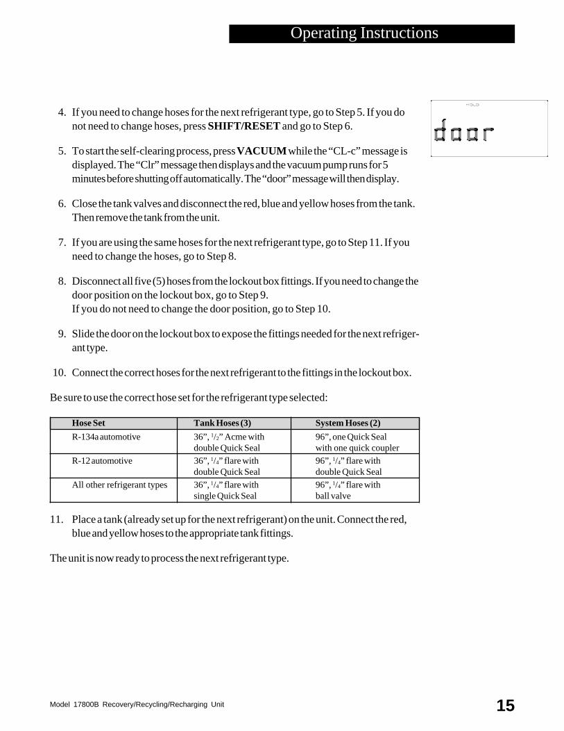
KEYPAD FUNCTIONS
In addition to the number keys, the keypad containsspecial keys that accomplish specific operating functions.
• RECYCLE — Activates the recyclingsequence when pressed at the same time as theSHIFT/RESET key.
• RECOVER — Activates the recoverysequence.
• SHIFT/RESET — Accesses the “PROGRAM” mode and moves from one pro-gram function to the next.
• FILTER — When pressed at the same time as the SHIFT/RESET key, automati-cally recovers and evacuates to 13 inches of vacuum from the filter and low side ofthe unit so you can change the filter.
• CHG — Automatically charges the A/C-R system with theprogrammed amount of refrigerant.
• HOLD/CONT — Interrupts the “AUTOMATIC” cycle (HOLD ), and then re-sumes functions (CONT). Press once for HOLD , and againfor CONT (continue).
• VACUUM — Activates the vacuum process.
• ENTER — Enters programmed data into the unit’s memory.
Diagram of Digital Display
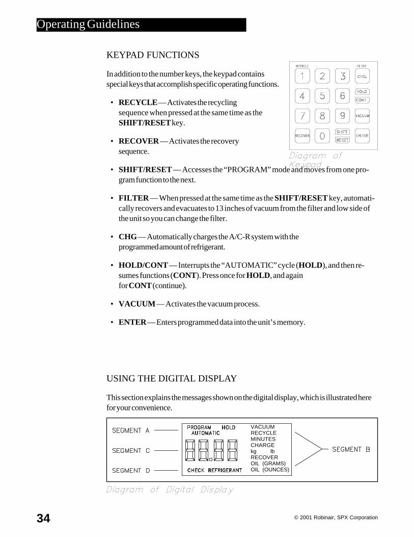
USING THE DIGITAL DISPLAY
This section explains the messages shown on the digital display, which is illustrated herefor your convenience.
Diagram ofKeypad
Operating Guidelines
VACUUMRECYCLEMINUTESCHARGEkg lbRECOVEROIL (GRAMS)OIL (OUNCES)
Model 17800B Recovery/Recycling/Recharging Unit 35
Segment A — Indicates in which mode the unit is operating:
PROGRAM — The unit is in the programming mode, which allows you to pro-gram vacuum time and refrigerant weight or to review the existing program.
HOLD — This mode is used to change a refrigerant tank or to interrupt thevacuum/charging/recovery cycles.
AUTOMATIC — Indicates that the unit is running in a given cycle and willautomatically stop when the cycle is complete. One exception: the recycling processmust be stopped by pressing HOLD/CONT .
Segment B — Indicates that the unit is either evacuating the A/C-R system or recover-ing, recycling, or recharging refrigerant or that the unit is ready to be programmed forone of the following functions.(Use the chart on the next page as a quick reference for interpreting Segment B mes-sages.)
VACUUM
• With PROGRAM, indicates that the unit is ready to be programmed for vacuum.
• With AUTOMATIC, indicates that the vacuum pump is running; the numberdisplayed counts down in minutes and seconds, showing the amount of time remain-ing.
• With HOLD, indicates that HOLD/CONT was pressed to interrupt the vacuumcycle.
RECYCLE
• With AUTOMATIC, indicates the unit is recycling refrigerantfrom the tank.
CHARGE
• With PROGRAM, indicates that the unit is ready to beprogrammed for the amount of refrigerant to be charged into theA/C-R system; on the keypad enter the charge in pounds and hundredths of apound or kilograms, depending on the measurement mode selected.
• With AUTOMATIC, indicates the unit is charging refrigerant into the A/C-R system;the number shown on the digital display counts down, showing the remaining amountof refrigerant to be dispensed.
• With HOLD, indicates that HOLD/CONT was pressed to interrupt the chargingcycle; the number shown on the digital display is the amount of refrigerant remaining
Operating Guidelines

© 2001 Robinair, SPX Corporation36
to be charged into the A/C-R system; to continue charging, press HOLD/CONT again.
RECOVER
• With AUTOMATIC, indicates the unit is recovering refrigerant from the A/C-Rsystem and shows the amount of refrigerant recovered in pounds or kilograms,depending on the measurement mode selected.
OIL(OUNCES) or OIL(GRAMS)
• Lights up as a reminder to drain the oil separator after each job.
Segment C — Shows a number or a coded error message on the digital display thatindicates the unit’s operating status or any specific problems. See Troubleshooting for alist of error codes and messages.
Segment D — Indicates that refrigerant is low — approximately six pounds (or 2.7kilograms) of refrigerant is left in the tank. Eitherreplace the tank or add refrigerant to the tank.
VACUUM + PROGRAM = Program unit for vacuumVACUUM + AUTOMATIC = Vacuum pump is runningVACUUM + HOLD = Interrupted vacuum cycle
RECYCLE + AUTOMATIC = Unit is recycling refrigerant
CHARGE + PROGRAM = Pr ogram unit for chargeCHARGE + AUTOMATIC = Unit is charging A/C-R systemCHARGE + HOLD = Interrupted charging cycle
RECOVER + AUTOMATIC = Unit is recovering refrigerant
Quick Reference Chart for Segment B
Operating Guidelines

Model 17800B Recovery/Recycling/Recharging Unit 37
USING THE DIAGNOSTIC MODE
The diagnostic mode allows you to run individual components or retrieve stored informa-tion. To access the diagnostic mode, you must press and hold SHIFT/RESET and thenpress ENTER. The display will show the message “FUNC.” To exit the diagnosticmode, press SHIFT/RESET again.
Some diagnostic functions exit the diagnostic mode when completed so to continue withmore diagnostic functions you must re-enter the diagnostic mode.
Once in the diagnostic mode you can do the following:
Initial Vacuum Mode:
1. Press 1 to enter initial vacuum mode. The display will show the message“VACUUM.” The proper use of this mode is described in the intial set up instruc-tions which begin on page 6.
2. Press HOLD/CONT to stop the pump.
Set display for pounds or kilograms:
1. Press “0” to display the unit of measure currently set (the unit assumes you want tochange the setting).
2. Press ENTER to toggle between "lb" and "kg".
3. When the desired setting displays, press SHIFT/RESET to save the selection.
Display total weight of recovered refrigerant:
1. Press “3” to display the total amount of refrigerant recovered by unit since the lastfilter-drier change.
2. This counter resets with every filter-drier change.
To Test Full Display:
I m p o r t a n t :To accessthe diag-nosticmode, youmustpress andholdSHIFT/RE-SET andpress EN-TER. Thedisplaywill showthe mes-sage�FUNC.� Toexit thediagnosticmode,pressSHIFT/RE-SET again.
Operating Guidelines

© 2001 Robinair, SPX Corporation38
1. Press “5” to see the complete LCD display, which only displays momentarilybefore returning to the Program mode.
2. Press any key to exit.
To Access Scale Function:
1. Press “6” to “zero out” the display (regardless of what is on the scale platform).The weight of anything you add to the scale platform will now display.
2. Press SHIFT/RESET to exit.
To Display Weight of Refrigerant in Tank:
1. Press “7” to display the weight of refrigerant in the tank.
2. Press any key to exit.
Example of Full Display Test
Operating Guidelines
VACUUMRECYCLEMINUTESCHARGEkg lbRECOVEROIL (GRAMS)OIL (OUNCES)

Model 17800B Recovery/Recycling/Recharging Unit 39
USING DISPLAY CODES
134A R-134a; indicates R-134a automotive refrigerantrequiring 1/2” Acme fittings.
Add Add refrigerant to the tank before starting charging procedures.
CAL The scale is out of calibration; see Calibrating the Scale.
Check Tank has six (6) pounds or less of refrigerant;Refrigerant charging will not activate.
CH-F Change compressor oil and filter/drier; 200 pounds of refrigerant hasbeen recovered since the last change.
CH-P A/C-R system pressure is low; prevents pulling air into the unit from aleaky system.
CL-c Clearing complete; indicates that the first stage of the clearing processis complete.
CL-L The low side clearing routine is in progress; this occurs when youpress RECOVER and can last up to fourminutes.
Clr Self-clearing; if this message is displayed, the unit is in the self-clearingprocess.
CON The vacuum pump will run continuously; pressSHIFT/RESET to stop.
CPL Complete; the current procedure is finished.
door (Flashes) The unit has been cleared and you can now select a door
Operating Guidelines

© 2001 Robinair, SPX Corporation40
position. Slide the refrigerant lockout panel (located on the back of the unit, top leftcorner) to expose the fittings for the selected refrigerant type.
OIL/drn (Flashes alternately) Drain; open the oil drain valve to relieve thepressure in the unit.
FIL Compressor oil and filter/drier change procedures are being per-formed.
FULL The tank is full; recovery stops automatically.
HI-P High pressure; the unit pressure is greater than 435 psi.
OIL Change vacuum pump oil; it has been 10 hours since the last oilchange.
R12 R-12; indicates R-12 or other refrigerant type requiring1/4” flare fittings.
SCAL Scale problem; the scale is broken or disconnected, or the tank hasexceeded 75 pounds gross weight.
U-HI High pressure to vacuum pump; prevents blowingrefrigerant through the vacuum pump. To relievepressure, perform a recovery process (see the Operating Instruc-tions).
Operating Guidelines

Model 17800B Recovery/Recycling/Recharging Unit 41
Following is a list of replacement parts and accessories you may need toservice or maintain your unit. Tanks, filter-drier and vacuum pump oil shouldbe purchased through your regular Robinair distributor.
Description 115-Volt 230-Volt
50 lb. (23 kg) tank,1/4” flare fittings ----------------------------------------------17506 1750650 lb. (23 kg) tank,1/2” Acme fittings ---------------------------------------------34750 3475036” Yellow Hose, Single Quick Seal ---------------------------------------------19293 1929336” Red Hose, Single Quick Seal ------------------------------------------------68336A 68336A36” Blue Hose,Single Quick Seal w/valve core depressor -------------------19339 1933936” Red Hose, Auto Shut Off ---------------------------------------------------19312 1931236” Blue Hose,Auto Shut Off ---------------------------------------------------19311 1931136” Yellow Hose,Auto Shut Off -------------------------------------------------19310 1931036” Blue Acme Hose --------------------------------------------------------------19306 1930636” Red Acme Hose --------------------------------------------------------------19307 1930736” Yellow Acme Hose -----------------------------------------------------------19313 1931396” Red Hose, With Ball Valve --------------------------------------------------19296 1929696” Blue Hose, With Ball Valve -------------------------------------------------19298 1929896” Red Hose, Auto Shut Off ---------------------------------------------------19308 1930896” Blue Hose, Auto Shut Off ---------------------------------------------------19309 1930996” Red Acme Quick Seal Hose ------------------------------------------------19328 1932896” Blue Acme Quick Seal Hose ------------------------------------------------19329 19329Coupler (1/2 Acme x Service Coupler) --------------------------------------------16301 16301Copeland Compressor ------------------------------------------------------------RA19775 RA19785Thomas Oil-Less Compressor ---------------------------------------------------RA19782 RA19783Quick Change Filter ---------------------------------------------------------------19776 19776Gauge, Air Purge ------------------------------------------------------------------RA19281 RA19285Gauge, High Side ------------------------------------------------------------------RA19787 RA19787Gauge, Low Side ------------------------------------------------------------------RA19786 RA19786Indicator Light (Amber) ----------------------------------------------------------RA17107 RA19351Keypad -----------------------------------------------------------------------------RA19065 RA19065Main Circuit Board ----------------------------------------------------------------RA19774 RA19774Relay Board ------------------------------------------------------------------------RA19778 RA19784R-134a Low Side Coupler--------------------------------------------------------18190A 18190AR-134a High Side Coupler --------------------------------------------------------18191A 18191AScale--------------------------------------------------------------------------------RA19773 RA19773Vacuum Pump Oil (1 case of quart bottles) ------------------------------------13203 13203
Replacement Parts
Wiring DiagramINST0923Flow DiagramINST0924

© 2001 Robinair, SPX Corporation42
INST0923
Flow Diagram

Model 17800B Recovery/Recycling/Recharging Unit 43
Wiring Diagram
INST0924
© 2001 Robinair, SPX Corporation44
RECOVERY OPERATION
Compressor does not start
Problem: Main power switch is offSolution: Turn on switch
Problem: Power cord is not plugged in or there is no power at plugSolution: Check circuit for power
Problem: “FULL” message shows on digital displaySolution: Change tanks (see Installing a Tank and Pulling A Vacuum)
Problem: “HI-P” message shows on digital displaySolution: Be sure tanks valves are open and hoses are properly connected to the
tank, orCheck for air in the tank (recycle tank to purge any air), orCheck the scale calibration (see Checking the Scale Accuracy)
Note: If "HI-P" message does not disapear in 20 minutes the pressure willhave to be released manually. Recover the pressure from the HI-P AccessPort shown on page 4 in the Diagram of Units Components - Internal View.
Problem: “CH-F” message on digital displaySolution: Remove and replace the filter-drier (see Replacing the Filter-
Drier), and be sure to pull a vacuum before continuing
Runs for a short time but does not complete recovery
Problem: Tank valves are closedSolution: Open both valves and be sure hoses are properly
connected to the tank
Problem: Manifold valves are closedSolution: Open both valves
Troubleshooting

Model 17800B Recovery/Recycling/Recharging Unit 45
Runs but will not shut off
Problem: Oil drain valve is openSolution: Close the oil drain valve
Problem: There is a leak in the A/C-R systemSolution: Locate and repair all system leaks
Problem: Hoses are not properly connected to the vehicleSolution: Check hose connections
Problem: Oil return solenoid is openSolution: Replace the oil return solenoid
RECYCLING OPERATION
Compressor does not start or stops prematurely
Problem: Power cord is not plugged in or there is no power at plugSolution: Check circuit for power
Problem: Tank valves are closedSolution: Open both valves and be sure hoses are properly
connected to the tank
Problem: “CH-F” message on digital displaySolution: Remove and replace the filter-drier (see Replacing the Filter-
Drier), and be sure to pull a vacuum before continuing
Refrigerant does not flow
Problem: Refrigerant supply empty or lowSolution: Add refrigerant to the tank
Problem: Tank valves are closedSolution: Open both valves and be sure hoses are properly
connected to the tank and the unit
Troubleshooting

© 2001 Robinair, SPX Corporation46
RECHARGING OPERATION
No power when MAIN POWER switch is on — no display showing
Problem: Power cord is not plugged in or there is no power at plugSolution: Check circuit for power
Problem: The “CHECK REFRIGERANT” message is displayedSolution: There is less than 6 pounds of refrigerant in the tank; add refrigerant to
the tank
Audible tone sounds during refrigerant transfer
Problem: Transfer stopped or too slowSolution: Close the high side valve, then start the A/C-R system and pull the
remaining refrigerant into the system
Problem: Refrigerant supply is low or emptySolution: Add refrigerant to the tank or change tanks
Problem: Tank valves are closedSolution: Open both valves and be sure hoses are properly
connected to the tank and the unit
Troubleshooting

Model 17800B Recovery/Recycling/Recharging Unit 47
EVACUATION OPERATION
Vacuum pump will not start
Problem: Power cord is not plugged in or there is no power at plugSolution: Check circuit for power
Problem: The pressure in the A/C-R system is too highSolution: Recover the remaining A/C-R system charge
Problem: “U-HI” message on digital displaySolution: Recover all refrigerant before pulling a vacuum
Problem: Vacuum time not enteredSolution: Program the required time for vacuum
Vacuum pump runs but low side gauge does not register anappropriate vacuum
Problem: Low side valve is closedSolution: Open the low side valve
Problem: Pump oil is contaminatedSolution: Flush and change the vacuum pump oil
Problem: Hose connection is loose or manifold is leakingSolution: Check connections
CLEARING OPERATION
“CLR” displays on screen
Problem: Pressing HOLD/CONT does not clear the displaySolution: Slide the lockout panel on the back of the unit to expose the fittings for
the correct refrigerant type, connect the appropriate hoses and perform aclearing procedure (see Step 12 in Set Up Instructions)
Troubleshooting

© 2001 Robinair, SPX Corporation48
This product is warranted to be free from defects in workmanship, materials, and com-ponents for a period of one year from date of purchase. All parts and labor required torepair defective products covered under the warranty will be at no charge. The followingrestrictions apply:
1. The limited warranty applies to the original purchaser only.
2. The warranty applies to the product in normal usage situations only, as described inthe Operating Manual. The product must also be serviced and maintained asspecified.
3. If the product fails, it will be repaired or replaced at the option of the manufacturer.
4. Transportation charges for warranty service will be reimbursed by the factory uponverification of the warranty claim and submission of a freight bill for normal groundservice. Approval from the manufacturer must be obtained prior to shipping to anauthorized service center.
5. Warranty service claims are subject to authorized inspection forproduct defect(s).
6. The manufacturer shall not be responsible for any additional costs associated with aproduct failure including, but not limited to, loss of work time, loss of refrigerant,cross-contamination of refrigerant, and unauthorized shipping and/or labor charges.
7. All warranty service claims must be made within the specified warranty period.Proof-of-purchase date must be supplied to the manufacturer.
8. Use of this recovery/recycling equipment with unauthorized refrigerants will void thewarranty. Authorized refrigerants are listed on the equipment or are availablethrough the Technical Service Department.
This Limited Warranty does not apply if:
•The product, or product part, is broken by accident. •The product is misused, tampered with, or modified. •The product is used for recovering or recycling any substance other than the specified
refrigerant type.
Note: Refillable refrigerant tanks are reusable.
I m p o r t a n t !Please havemodel number,serial number,date code andproof of purchase(invoice) readywhen you call forauthorization.
Limited Warranty

Model 17800B Recovery/Recycling/Recharging Unit 49
A/C-R System Evacuation 14
Adding Refrigerant to the Tank 18
Air Purge Gauge, Diagram 15
Calibrating the Scale 27
Circuit Calibration, UL 28
Changing Refrigerant Types 12
Changing the Compressor Oil 24
Changing the Filter-Drier 24
Changing the Vacuum Pump Oil 23
Charging Procedures 16
Checking for Leaks 30
Confirming the Scale Checklist 26
Control Panel, Diagram 5,10,31
Control Panel, Using 31
Components, Diagram of Unit’s 4,5,6,12
Correcting an Incomplete Transfer 17
Diagnostic Mode, Using 35
Digital Display, Diagram 32
Digital Display, Using 32
Display Codes, Using 37
Evacuation, A/C-R System 14
Filter-Drier, Diagram 25
Filter-Drier Installation, Diagram 8
Flow Diagram 40
General Operating Guidelines 3
Glossary of Terms 1
Hose Connections, Lockout Box 7
Introduction 2
Keypad, Diagram 32
Keypad Functions 32
Leaks, Checking 30
Limited Warranty 46
Maintenance Procedures 23
Calibrating the Scale 27
Changing the Compressor Oil 24
Changing the Filter-Drier 24
Changing the Vacuum Pump Oil 23
Checking for Leaks 30
Correct Weight Verification 26
Operating Guidelines 31
Keypad Functions 32
Using the Control Panel 31
Using the Diagnostic Mode 35
Using the Digital Display 32
Using Display Codes 37
Operating Instructions 10
A/C-R System Evacuation 14
Adding Refrigerant to the Tank 18
Changing Refrigerant Types 12
Charging Procedures 16
Correcting An Incomplete Transfer17
Recovery Procedures 10
Recycling Procedures 15
Overview 20
Charging 22
Evacuation 21
Recovery 20
Recycling 21
Quick Reference Chart for Segment B 31
Recycling Procedures 15
Recovery Procedures 10
Replacement Parts 39
Scale, Calibrating the 27
Scale Checklist, Confirming 26
Set Up Instructions 4
Threaded Screws, Diagram 30
Troubleshooting 42
Clearing Operation 45
Evacuation Operation 45
Recharging Operation 44
Recovery Operation 42
Recycling Operation 43
UL Circuit Calibration 28
Unit’s Components, Diagram 4,5,6,12
Using the Control Panel 31
Using the Diagnostic Mode 35
Using the Digital Display 32
Using Display Codes 37
Vacuum Pump Components, Diagram9,23
Warranty, Limited 46
Wiring Diagram 41
This equipment is protected by one or more of the followingU.S. and foreign patents.
U.S. Patents: 4,523,897; 4,688,388 Re 33,212; 4,768,347; 4,805,416; 4,878,356;4,938,031; 5,005,369; 5,005,375;5,038,578; 5,042,271; 5,063,749; 5,095,713; 5,181,391; 5,203,177; 5,231,842;5,248,125.
Foreign Patents:AUS 609,240; 613,058; 622,833; 633,766. BRAZ PI 8803612.CAN 616,474; 1,311,621; 1,311,622; 2,012,620; 2,026,348.EUR 0 315 296; 0 329 321 B1; 0 437 021 B1.MEX 16208. SAF 88/4981.
Other U.S. and Foreign Patents Pending.
Manufactured by Robinair, SPX Corporation,Montpelier, OH 43543. PRINTED IN USA.
Index

© 2001 Robinair, SPX Corporation50124048 (Rev. 5/01) Printed In USA
Call toll-free
Technical Support Line
800-822-5561in the continental U.S. or Canada.
In all other locations, contact your local distributor. To help us serve youbetter, please be prepared to provide the model number, serial number,and date of purchase.
To validate your warranty, you must complete the warranty card at-tached to your unit and return it within ten days from date of purchase.
• NATIONWIDE NETWORK OF AUTHORIZED SERVICE CENTERS
If your unit needs repairs or replacement parts, you should contact theservice center in your area. For help in locating a service center, call thetoll free technical support line.
CONVERSIONTABLE
OZ. LBS.
0.5 0.031.0 0.061.5 0.092.0 0.132.5 0.163.0 0.193.5 0.224.0 0.254.5 0.285.0 0.315.5 0.346.0 0.386.5 0.417.0 0.447.5 0.478.0 0.508.5 0.539.0 0.569.5 0.5910.0 0.6310.5 0.6611.0 0.6911.5 0.7212.0 0.7512.5 0.7813.0 0.8113.5 0.8414.0 0.8814.5 0.9115.0 0.9415.5 0.9716.0 1 lb.
Due to ongoing product improvements,we reserve the right to change design,specifications and materials without notice.
Model 17800B Recovery/Recycling/Recharging Unit
(
This equipment is designed to meet all applicable agency certificationsincluding Underwriter's Laboratories, Inc., SAE Standards and CUL.Proper maintenance of this equipment will provide accurate A/C ser-vice for many years.
Certain state and local jurisdictions dictate that using this equipment tosell refrigerant by weight may not be permitted. We recommend charg-ing for any A/C service by the job performed.
This weight scale provides a means of metering the amount of refriger-ant needed for optimum A/C system performance as recommended byOEM manufacturers.manufacturers.manufacturers.manufacturers.manufacturers.