Embed Size (px)
Citation preview

Title: Fire Resistance Test In Accordance With BS EN 1364-1: 1999 On A Glazed Screen Assembly
WF Report No:
164311, Issue 2
Prepared for:
AGC Flat Glass Europe. Chaussee de la Hulpe 166 1170 Brussels.
Date:
19th October 2007
Notified Body No:
0833
0249

WFRC Test Report No. 164311,
Issue 2
Page 2 of 37
Summary Objective To determine the fire resistance of a symmetrical insulated glazed screen
assembly when tested in accordance with BS EN 1364-1: 1999.
Sponsor AGC Flat Glass Europe, Chaussee de la Hulpe 166, 1170 Brussels.
Summary of Tested Specimens
The specimen comprised a hardwood (species: Meranti) framed glazed screen of overall dimensions 2950 mm wide by 2950 mm high and included mullions and transoms to form eight apertures. The apertures were glazed with 16 mm thick ‘Pyrobel 16’ glass.
Test Results:
Integrity Performance Sustained flaming 53 minutes
Gap gauge 52 minutes
Cotton Pad 50 minutes
44 minutes Insulation
5 kW/m2 54 minutes*
10 kW/m2 54 minutes*
15 kW/m2 54 minutes*
20 kW/m2 54 minutes*
Radiation Performance
25 kW/m2 54 minutes*
* The test duration. The test was discontinued after a period of 54 minutes.
Date of Test 25th July 2007
This report may only be reproduced in full. Extracts or abridgements of reports shall not be published without permission of Bodycote warringtonfire.

WFRC Test Report No. 164311,
Issue 2
Page 3 of 37
Signatories
Responsible Officer N. Howard* Testing Officer
Approved A. Kearns* Technical Manager
Head of Department S. Hankey* Operations Manager
For and on behalf of Bodycote warringtonfire. Report Issued Date : 19th October 2007
Issue 2 : Modification to text on summary page (29th June 2009)
This version of the report has been produced from a .pdf format electronic file that has been provided by Bodycote warringtonfire to the sponsor of the report and must only be reproduced in full. Extracts or abridgements of reports must not be published without permission of Bodycote warringtonfire. The original signed paper version of this report, which includes signatures in blue ink, is the sole authentic version. Only original paper versions of this report bear authentic signatures of the responsible Bodycote warringtonfire staff.

WFRC Test Report No. 164311,
Issue 2
Page 4 of 37
CONTENTS PAGE NO.
SUMMARY.................................................................................................................................. 2
SIGNATORIES............................................................................................................................ 3
TEST PROCEDURE...................................................................................................................... 5
TEST SPECIMEN ........................................................................................................................ 6
SCHEDULE OF COMPONENTS .................................................................................................. 11
INSTRUMENTATION................................................................................................................ 14
TEST OBSERVATIONS.............................................................................................................. 15
TEST PHOTOGRAPHS............................................................................................................... 17
TEMPERATURE AND DEFLECTION DATA ................................................................................. 20
PERFORMANCE CRITERIA AND TEST RESULTS....................................................................... 35
ONGOING IMPLICATIONS....................................................................................................... 36
CONCLUSIONS ........................................................................................................................ 36
FIELD OF DIRECT APPLICATION............................................................................................. 37

WFRC Test Report No. 164311,
Issue 2
Page 5 of 37
Test Procedure The glazed screen is required to provide a fire separating function and was therefore tested in accordance with BS EN 1364-1: 1999 ‘Fire resistance tests for non-loadbearing elements - Part 1: Walls’. This test report should be read in conjunction with that Standard and with BS EN 1363-1: 1999, ‘Fire resistance tests - Part 1: General requirements’ and BS EN 1363-2: 1999, ‘Fire resistance tests - Part 2: Alternative and additional procedures’.
Introduction
The specimen was judged on its ability to comply with the performance criteria for integrity, as required by BS EN 1364-1: 1999.
Fire Test Study Group/EGOLF
Certain aspects of some fire test specifications are open to different interpretations. The Fire Test Study Group and EGOLF have identified a number of such areas and have agreed Resolutions which define common agreement of interpretations between fire test laboratories which are members of the Groups. Where such Resolutions are applicable to this test they have been followed.
The test was conducted on the 25th July 2007 at the request of AGC Flat Glass Europe, the sponsor of the test.
Instruction to test
Mr F. Bonnefoy and Mr. Rase, representatives of the test sponsor witnessed the test.
Test Specimen Construction
A comprehensive description of the test construction is given in the Schedule of Components. The description is based on a detailed survey of the specimens and information supplied by the sponsor of the test.
Installation The specimen was installed into a refractory concrete lined steel restraint frame by representatives of the test sponsor on the 27th June 2007.
Conditioning The specimens’ storage, construction, and test preparation took place in the test laboratory over a total, combined time of 10 days. Throughout this period of time both the temperature and the humidity of the laboratory were measured and recorded as being within a range of from 15oC to 23oC and 29% to 95% respectively.
WFRC Test Report No. 164311,
Issue 2
Page 6 of 37
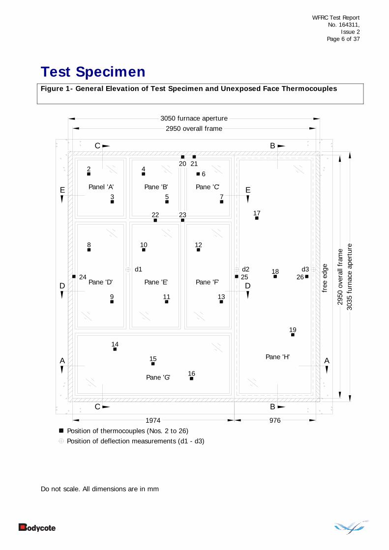
Test Specimen Figure 1- General Elevation of Test Specimen and Unexposed Face Thermocouples
Do not scale. All dimensions are in mm
Position of thermocouples (Nos. 2 to 26)
3050 furnace aperture
3035
fur
nace
ape
rtur
e
A
Position of deflection measurements (d1 - d3)
9761974
2950 overall frame
2950
ove
rall
fram
e
A
B
B
C
C
D D
E E
Pane 'G'
Pane 'H'
Pane 'F'Pane 'E'Pane 'D'
Pane 'C'Pane 'B'Panel 'A'
free
edg
e
4
5
2
3
6
7
8
9
10
11
12
13
14
16
15
2120
17
19
2322
182625
d1 d2 d324

WFRC Test Report No. 164311,
Issue 2
Page 7 of 37
Figure 2 – Horizontal Section A-A Through Specimen
Do not scale. All dimensions are in mm
FIRE
27
7
120
33
590
05
60
20
733
337
27
40
12
518
98
6060
3050
fur
nace
ape
rtur
e
976
1974
2950
ove
rall
fram
e
5
8
1
3
4
53
7
54
8
207
60
3
2
5
30
5
5
30
5
33
86
30
30
86
free
edg
e pa
cked
with
insu
latio
n
2
1
4
5
3
anchorbolts
1
1
6

WFRC Test Report No. 164311,
Issue 2
Page 8 of 37
Figure 3 – Vertical Section B-B through Specimen
Do not scale. All dimensions are in mm
30
5
30
5
260
7
20
8
4
3
1
85
2950
ove
rall
fram
e
3035
fur
nace
ape
rtur
e
337
20
605
4
5
2874
60
586
3
1
FIRE
anchorbolts
packers

WFRC Test Report No. 164311,
Issue 2
Page 9 of 37
Figure 4 – Vertical Section C-C through Specimen
Do not scale. All dimensions are in mm
FIRE
5
30
5
2
60
7
20
8
4
1
3
8
5
2950
ove
rall
fram
e30
35 f
urna
ce a
pert
ure
7
605
27
100
2746
5
5
20
77
20
5
30
5
4
530
5
572
212
90
5
750
4 5
2033
5
4
5
33
46
30
30
86
86
5
2
3
1
2
3
31
packers

WFRC Test Report No. 164311,
Issue 2
Page 10 of 37
Figure 5 – Typical Horizontal Section D-D & E-E through Specimen
Do not scale. All dimensions are in mm
FIRE
4
4
5
1974
595
207
60
33
5
5
8
7
5
30
5
5
5
2720
120
3333
20 27
4012
5
6060
20
4627
100
20 27
596
595
5
5
30
86
100
465
30
5
30
86
7
1
1
3
3
2
3
3
2

WFRC Test Report No. 164311,
Issue 2
Page 11 of 37
Schedule of Components (Refer to Figures 1 to 5) (All values are nominal unless stated otherwise) (All other details are as stated by the sponsor) Item
Description
1. Framework Material : Hardwood, species Meranti Density : 550 kg/m3 (stated) Details of Fixings to masonry surround i. type : Anchor bolts ii. reference : Hilti 100 HT iii. spacing : 450 mm Frame joints : Tenon joint, with 2 no. steel screws per joint 2. Glass Manufacturer : AGC Flat Glass Europe SA Reference : Pyrobel 16 Thickness : 17.3 +/- 1.0 mm Overall pane sizes i. pane ‘A’ : 595 mm wide x 722 mm high ii. pane ‘B’ : 596 mm wide x 722 mm high iii. pane ‘C’ : 595 mm wide x 722 mm high iv. pane ‘D’ : 595 mm wide x 1290 mm high v. pane ‘E’ : 596 mm wide x 1290 mm high vi. pane ‘F’ : 595 mm wide x 1290 mm high vii. pane ‘G’ : 1898 mm wide x 750 mm high viii. pane ‘H’ : 900 mm wide x 2874 mm high Glass Label References i. pane ‘A’ : BX 08057-14-502 ii. pane ‘B’ : BX 08057-14-501 iii. pane ‘C’ : BX 08057-14-503 iv. pane ‘D’ : BX 08057-15-501 v. pane ‘E’ : BX 08057-15-502 vi. pane ‘F’ : BX 08057-15-503 vii. pane ‘G’ : BX 08057-16-501 viii. pane ‘H’ : BX 08057-17-501 Details of Packers (base of glass) i. material : Promatect H ii. overall section size : 18 mm wide x 5 mm thick iii. size : 70 mm long 3. Glazing Bead Material : Hardwood, species Meranti Density : 550 kg/m3 (stated) Fixing method : Screws Details of Screws i. type : Countersunk head steel screws ii. size : 60 mm long x 4 mm diameter iii. spacing : 215 mm to 240 mm centres (90 mm in from outside
corners).

WFRC Test Report No. 164311,
Issue 2
Page 12 of 37
Item
Description
4. Glazing Seal Manufacturer : Odice SA Reference : Superwool X607 Material : Ceramic fibre Overall section size : 20 mm wide x 5 mm thick 5. Glazing Sealant Manufacturer : Dow Corning Reference : Firestop 700 Material : Silicone 6. Module Fixings Type : Countersunk head steel screws Size : 60 mm long x 5 mm diameter Spacing : 300 mm centres along full hieght 7. Architraves Material : Hardwood, species Meranti Density : 550 kg/m3 (stated) Fixing method : Screw fixed over module butt joint Details of Screws i. type : Countersunk head steel screws ii. reference : 35 mm long x 3.5 mm diameter iii. spacing : 280 mm centres along full hieght 8. Perimeter Insulation Reference : Insulfrax Material type : Ceramic fibre Density : 96 kg/m3 (stated)

WFRC Test Report No. 164311,
Issue 2
Page 13 of 37
Sampling Mr. I. Laithwaite, a representative of Bodycote warringtonfire, sampled the glass for the test.
Manufacturer: Glaverbel S.A./N.V. Manufacturing plant: Olovi, Czech Republic Place of sampling: Warehouse at Olovi Number/quantity of samples: 3 x Pyrobel 16 stock glass sheets of 315cm x
225 cm. Manufacturers marks: Label refs:
BX08057-14-502 BX08057-14-501 BX08057-14-503 BX08057-15-501 BX08057-15-502 BX08057-15-503 BX08057-16-501 BX08057-17-501
Samplers marks: I. Laithwaite signature to all panes Date of sampling: 12th June 2007
Notified body number: 1121

WFRC Test Report No. 164311,
Issue 2
Page 14 of 37
Instrumentation
General The instrumentation was provided in accordance with the requirements of the Standard.
Furnace The furnace was controlled so that its mean temperature complied with the requirements of BS EN 1363-1: 1999, Clause 5.1, using nine plate thermometers, distributed over a plane 100 mm from the surface of the test construction.
Roving Thermocouple
A roving thermocouple was available to measure temperatures on the unexposed surface of the specimen at any position which might appear to be hotter than the temperatures indicated by the fixed thermocouples.
Integrity Criteria Cotton pads and gap gauges were available to evaluate the integrity of the specimen.
Furnace Pressure The furnace atmospheric pressure was controlled so that it complied with the requirements of BS EN 1363-1: 1999, Clause 5.2. The calculated pressure differential relative to the laboratory atmosphere at the top of the specimen was 20 (+0/-3) Pa.

WFRC Test Report No. 164311,
Issue 2
Page 15 of 37
Test Observations Time All observations are from the unexposed face unless noted otherwise.
mins secs The ambient air temperature in the vicinity of the test construction was 16ºC at the start of the test with a maximum variation of +1ºC during the test.
00 00 The test commences.
00 50 Crackling sounds are heard from the specimen.
01 10 Large segments of glass crack and fall into the furnace chamber.
01 40 The upper 2/3 of the specimen begin to turn opaque in appearance.
02 30 Slight smoke release is evident from pane H.
06 00 The exposed surface of the hardwood frame cracks now having a crazed effect and glows a dull orange in colour.
07 30 The entire unexposed surface of the glass has now reacted turning opaque in appearance.
09 30 The bottom section of frame to the exposed face of the assembly ignites causing large amounts of flaming within the furnace chamber.
11 50 Small segments of glass spit from the glass of pane E.
14 00 Small segments of glass spit from all panes of glass.
20 00 No further significant visible change.
21 00 Small segments of the exposed frame char and fall away into the furnace chamber.
30 00 The specimen continues to satisfy the integrity and insulation requirements of the test.
34 00 The smoke release mentioned earlier increases in volume emitting from the entire unexposed surface of the specimen.
42 00 The smoke release continues to increase in volume.
50 00 A cotton wool pad is applied to the specimen coincident with thermocouple 17 on pane H and ignites. Cotton wool pad integrity failure is deemed to occur.

WFRC Test Report No. 164311,
Issue 2
Page 16 of 37
Time
mins secs
52 00 A gap in excess of 6mm by 150mm is evident coincident with thermocouple 17. Gap gauge integrity failure is deemed to occur.
53 50 A large section of glass falls from pane H. Sustained flames issue from this area. Sustained flaming integrity failure is deemed to occur.
54 00 The test is discontinued at the sponsors request.

WFRC Test Report No. 164311,
Issue 2
Page 17 of 37
Test Photographs
The Unexposed Face Of The Test Construction Prior To Testing
The unexposed face of the test construction after a test duration of 2 minutes

WFRC Test Report No. 164311,
Issue 2
Page 18 of 37
The unexposed face of the test construction after a test duration of 5 minutes
The unexposed face of the test construction after a test duration of 30 minutes

WFRC Test Report No. 164311,
Issue 2
Page 19 of 37
The unexposed face of the test construction after a test duration of 45 minutes
The exposed face of the test construction directly after the test

WFRC Test Report No. 164311,
Issue 2
Page 20 of 37
Temperature and Deflection Data
Mean Furnace Temperature, Together With The Temperature/Time Relationship Specified In The Standard
Time Specified Actual
Furnace Furnace Mins Temperature Temperature
Deg. C Deg. C 0 20 29 2 445 483 4 544 556 6 603 621 8 646 667 10 678 698 12 706 713 14 728 737 16 748 760 18 766 776 20 781 786 22 796 793 24 809 831 26 820 824 28 832 827 30 842 851 32 852 868 34 860 879 36 869 871 38 877 870 40 885 896 42 892 919 44 899 905 46 906 905 48 912 906 50 918 909 52 924 919 54 930 933

WFRC Test Report No. 164311,
Issue 2
Page 21 of 37
Mean Temperature Recorded On The Unexposed Surface
Of The Glazing
Time Mean
Mins Temp Deg. C 0 20 2 27 4 57 6 76 8 90 10 103 12 112 14 118 16 120 18 118 20 113 22 111 24 111 26 114 28 119 30 125 32 133 34 142 36 152 38 162 40 172 42 183 44 197 46 212 48 230 50 255 52 273 54 293

WFRC Test Report No. 164311,
Issue 2
Page 22 of 37
Individual Temperatures Recorded On The Unexposed Surface
Of Pane A
Time T/C T/C Number Number
Mins 2 3 Deg. C Deg. C0 19 19 2 25 28 4 55 60 6 79 77 8 90 91 10 101 104 12 109 112 14 118 119 16 125 117 18 132 114 20 127 109 22 117 108 24 112 110 26 112 114 28 116 119 30 122 127 32 128 135 34 133 142 36 139 150 38 144 159 40 151 168 42 160 178 44 169 190 46 178 202 48 189 214 50 199 226 52 209 240 54 218 254

WFRC Test Report No. 164311,
Issue 2
Page 23 of 37
Individual Temperatures Recorded On The Unexposed Surface
Of Pane B
Time T/C T/C Number Number
Mins 4 5 Deg. C Deg. C0 20 20 2 26 27 4 52 59 6 67 76 8 77 88 10 91 101 12 107 113 14 116 123 16 123 117 18 127 108 20 118 102 22 111 100 24 109 100 26 111 101 28 114 104 30 119 108 32 127 114 34 135 123 36 144 131 38 155 140 40 162 147 42 166 154 44 179 162 46 195 171 48 213 182 50 234 195 52 258 210 54 284 226

WFRC Test Report No. 164311,
Issue 2
Page 24 of 37
Individual Temperatures Recorded On The Unexposed Surface
Of Pane C
Time T/C T/C Number Number
Mins 6 7 Deg. C Deg. C0 20 21 2 28 29 4 63 63 6 82 80 8 97 95 10 112 107 12 120 119 14 116 131 16 115 125 18 111 117 20 110 111 22 111 109 24 114 111 26 119 113 28 126 119 30 133 125 32 140 133 34 147 141 36 154 149 38 161 157 40 163 165 42 171 171 44 182 180 46 194 193 48 208 210 50 222 228 52 238 247 54 257 267

WFRC Test Report No. 164311,
Issue 2
Page 25 of 37
Individual Temperatures Recorded On The Unexposed Surface
Of Pane D
Time T/C T/C Number Number
Mins 8 9 Deg. C Deg. C0 22 22 2 29 31 4 63 67 6 81 84 8 93 98 10 106 113 12 118 123 14 130 130 16 140 125 18 134 120 20 123 118 22 119 121 24 121 127 26 125 135 28 131 143 30 137 154 32 144 165 34 153 177 36 164 188 38 176 200 40 187 212 42 198 226 44 211 241 46 225 256 48 237 271 50 250 287 52 263 303 54 277 321

WFRC Test Report No. 164311,
Issue 2
Page 26 of 37
Individual Temperatures Recorded On The Unexposed Surface
Of Pane E
Time T/C T/C Number Number
Mins 10 11 Deg. C Deg. C0 22 21 2 30 27 4 63 60 6 80 78 8 90 93 10 101 109 12 111 113 14 117 106 16 120 107 18 121 101 20 116 97 22 115 98 24 117 101 26 121 104 28 128 110 30 136 116 32 144 123 34 154 132 36 166 140 38 177 149 40 189 156 42 201 166 44 216 176 46 230 190 48 245 210 50 259 232 52 273 254 54 287 275

WFRC Test Report No. 164311,
Issue 2
Page 27 of 37
Individual Temperatures Recorded On The Unexposed Surface
Of Pane F
Time T/C T/C Number Number
Mins 12 13 Deg. C Deg. C0 22 22 2 30 30 4 63 65 6 81 82 8 95 96 10 108 110 12 117 121 14 125 127 16 135 132 18 138 134 20 131 130 22 123 126 24 119 126 26 119 129 28 123 133 30 127 141 32 133 150 34 139 161 36 145 173 38 154 185 40 164 198 42 177 211 44 192 227 46 208 244 48 224 260 50 240 276 52 255 292 54 271 310

WFRC Test Report No. 164311,
Issue 2
Page 28 of 37
Individual Temperatures Recorded On The Unexposed Surface
Of Pane G
Time T/C T/C T/C Number Number Number
Mins 14 15 16 Deg. C Deg. C Deg. C0 22 18 17 2 27 21 19 4 53 40 30 6 80 68 49 8 94 83 75 10 108 94 88 12 120 105 93 14 116 115 100 16 112 113 109 18 110 110 117 20 108 107 112 22 110 105 113 24 113 106 113 26 118 109 109 28 125 113 109 30 134 120 111 32 145 127 116 34 158 137 121 36 171 148 127 38 178 158 133 40 189 161 140 42 202 166 148 44 219 177 158 46 240 188 169 48 264 200 179 50 292 213 188 52 322 229 199 54 353 245 212

WFRC Test Report No. 164311,
Issue 2
Page 29 of 37
Individual Temperatures Recorded On The Unexposed Surface
Of Pane H
Time T/C T/C T/C Number Number Number
Mins 17 18 19 Deg. C Deg. C Deg. C0 18 18 18 2 27 26 24 4 55 54 53 6 70 79 75 8 81 95 88 10 93 101 100 12 104 104 110 14 109 106 116 16 111 107 121 18 105 105 121 20 102 103 112 22 100 102 107 24 99 103 105 26 99 105 107 28 100 110 110 30 105 117 116 32 113 127 124 34 126 140 134 36 143 156 143 38 170 172 151 40 199 185 161 42 239 196 171 44 281 211 182 46 317 229 195 48 372 249 208 50 561 269 222 52 591 288 235 54 655 306 249

WFRC Test Report No. 164311,
Issue 2
Page 30 of 37
Recorded Radiation Intensity
Time Radiation Intensity
Mins At 1 Metre kW/m2 0 0.00 2 0.11 4 0.18 6 0.26 8 0.27 10 0.33 12 0.37 14 0.43 16 0.43 18 0.38 20 0.42 22 0.43 24 0.35 26 0.39 28 0.43 30 0.45 32 0.53 34 0.54 36 0.65 38 0.73 40 0.81 42 0.93 44 0.98 46 1.16 48 1.34 50 1.60 52 1.86 54 2.38
WFRC Test Report No. 164311,
Issue 2
Page 31 of 37
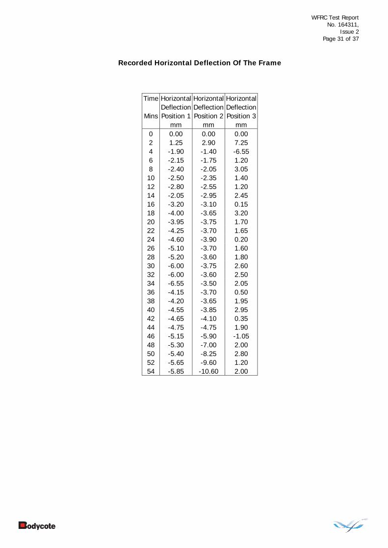
Recorded Horizontal Deflection Of The Frame
Time Horizontal Horizontal Horizontal Deflection Deflection Deflection
Mins Position 1 Position 2 Position 3 mm mm mm 0 0.00 0.00 0.00 2 1.25 2.90 7.25 4 -1.90 -1.40 -6.55 6 -2.15 -1.75 1.20 8 -2.40 -2.05 3.05 10 -2.50 -2.35 1.40 12 -2.80 -2.55 1.20 14 -2.05 -2.95 2.45 16 -3.20 -3.10 0.15 18 -4.00 -3.65 3.20 20 -3.95 -3.75 1.70 22 -4.25 -3.70 1.65 24 -4.60 -3.90 0.20 26 -5.10 -3.70 1.60 28 -5.20 -3.60 1.80 30 -6.00 -3.75 2.60 32 -6.00 -3.60 2.50 34 -6.55 -3.50 2.05 36 -4.15 -3.70 0.50 38 -4.20 -3.65 1.95 40 -4.55 -3.85 2.95 42 -4.65 -4.10 0.35 44 -4.75 -4.75 1.90 46 -5.15 -5.90 -1.05 48 -5.30 -7.00 2.00 50 -5.40 -8.25 2.80 52 -5.65 -9.60 1.20 54 -5.85 -10.60 2.00

WFRC Test Report No. 164311,
Issue 2
Page 32 of 37
Table Showing Recorded Furnace Pressure at 300 mm Below the Head of the Specimen
Time Recorded Pressure
Mins Pa 0 0 2 9 4 19 6 18 8 19 10 18 12 18 14 18 16 18 18 18 20 18 22 18 24 18 26 17 28 18 30 18 32 18 34 16 36 17 38 17 40 18 42 17 44 17 46 17 48 18 50 17 52 18 54 17

WFRC Test Report No. 164311,
Issue 2
Page 33 of 37
Graph Showing Mean Furnace Temperature, Together With The Temperature/Time Relationship Specified In The Standard
0
100
200
300
400
500
600
700
800
900
1000
0 10 20 30 40 50 60
Time - Minutes
Tem
pera
ture
- D
eg. C
Specified FurnaceTemperature Deg. C
Actual FurnaceTemperature Deg. C

WFRC Test Report No. 164311,
Issue 2
Page 34 of 37
Graph Showing Recorded Furnace Pressure at 300 mm Below the Head of the Specimen
0
2
4
6
8
10
12
14
16
18
20
0 10 20 30 40 50 60
Time - Minutes
Rec
orde
d P
ress
ure
- P
a

WFRC Test Report No. 164311,
Issue 2
Page 35 of 37
Performance Criteria and Test Results
Integrity Performance
It is required that the specimens retain their separating function, without:
Causing ignition of a cotton pad when applied Permitting the penetration of a gap gauge as specified in BS EN 1363-1: 1999 Sustained flaming on the unexposed surface These requirements were satisfied for the periods shown below:
Sustained flaming 53 minutes
Gap gauge 52 minutes
Cotton Pad 50 minutes
Insulation It is required that the mean temperature rise of the unexposed surface shall not be greater than 140C and that the maximum temperature rise shall not be greater than 180C. Insulation failure also occurs simultaneously with integrity failure. These requirements were satisfied for a period of 44 minutes after which time a mean temperature rise in excess of 140C was recorded.
Radiation Performance
The radiation intensity exceeded the values stated in BS EN 1363-2: 1999, at the following times:
5 kW/m2 54 minutes*
10 kW/m2 54 minutes*
15 kW/m2 54 minutes*
20 kW/m2 54 minutes*
25 kW/m2 54 minutes*
*The test duration. The test was discontinued after a period of 54 minutes

WFRC Test Report No. 164311,
Issue 2
Page 36 of 37
Ongoing Implications Limitations This report details the method of construction, the test conditions and the results
obtained when the specific element of construction described herein was tested following the procedure outlined in BS EN 1363-1: 1999, and where appropriate BS EN 1363-2: 1999. Any significant deviation with respect to size, constructional details, loads, stresses, edge or end conditions other than those allowed under the field of direct application in the relevant test method is not covered by this report. Annex A of BS EN 1363-1: 1999, provides guidance information on the application of fire resistance tests and the interpretation of test data.
Because of the nature of fire resistance testing and the consequent difficulty in quantifying the uncertainty of measurement of fire resistance, it is not possible to provide a stated degree of accuracy of the result.
Conclusions Evaluation against objective
A single specimen of a symmetrical, insulated glazed screen assembly when tested has been subjected to a fire resistance test in accordance with BS EN 1364-1: 1999, ‘Fire resistance tests for non-loadbearing elements - Part 1: Walls’, BS EN 1363-1: 1999, ‘General requirements’ and BS EN 1363-2: 1999, ‘Alternative and additional procedures’.
The specimen was judged on its ability to comply with the performance criteria for integrity, as required by BS EN 1634-1: 2000 and the radiation intensity values stated in BS EN 1363-2: 1999, and achieved the results detailed below:
Sustained flaming 53 minutes Integrity Performance
Gap gauge 52 minutes
Cotton Pad 50 minutes
Insulation 44 minutes
5 kW/m2 54 minutes* Radiation Performance
10 kW/m2 54 minutes*
15 kW/m2 54 minutes*
20 kW/m2 54 minutes*
25 kW/m2 54 minutes*
*The test duration. The test was discontinued after a period of 54 minutes

WFRC Test Report No. 164311,
Issue 2
Page 37 of 37
Field of Direct Application
General The results of this fire test are directly applicable to similar constructions where one or more of the changes listed below are made and the construction continues to comply with that appropriate design code for its stiffness and stability. Other changes are not permitted.
Decrease in the linear dimensions of panes. Change in the aspect ratio of panes provided that the largest dimension of the
pane and its area are not increased. Decrease in the distance between mullions and/or transoms. Decrease in the distance between fixing centres. Increase in the dimensions of framing members. Changed in the angle of installation by up to 10 from the vertical. No extension of height is allowed above that tested. The width of an identical construction may be increased if the specimen was
tested at a minimum of nominally 3.0 m wide with one vertical edge without restraint.
The result of a test of fire resistant glazing tested in one of the standard
supporting constructions given in EN 1363-1, or the test frame, is applicable to any other supporting construction within the same type (high density rigid, low density rigid or flexible) that has a greater fire resistance.

Bodycote warringtonfire Testing • Holmesfield Road • Warrington • Cheshire • WA1 2DS • United KingdomTel: +44 (0) 1925 655 116 • Fax: +44 (0) 1925 655 419 • Email: [email protected] • Website: www.warringtonfire.net