Embed Size (px)
Citation preview

TECNICA 140.1 - 142
cod. 988584
inver ter
TECNICA 141 - 161
CONTENTS PAGE
OPERATION AND WIRING DIAGRAMS................ 2
REPAIR GUIDE.......................................................10
SPARE PARTS LIST...............................................17
REPAIR SHEET......................................................19
Block diagram 2Analysis of the block diagram 3Illustrations 5Wiring diagrams 6
Equipment required 10General repair instructions 11Troubleshooting and remedies 11Testing the machine 14Illustrations 16
TROUBLESHOOTING
AND REPAIR MANUAL
TROUBLESHOOTING
AND REPAIR MANUAL
TROUBLESHOOTING
AND REPAIR MANUAL
TROUBLESHOOTING
AND REPAIR MANUAL
“reparation no problem !”

TECNICA 141 - 161
- 2 -
22
23
UN
DER
VO
LTA
GE
SA
FEG
UA
RD
25
24
11
12
13
17
19
201
23
45
67
89
10
14
15
16
18
FAN
PO
WER
SU
PP
LY
LED
FLY-B
AC
KP
OW
ER
SU
PP
LY
DR
IVER
OU
TP
UT
CU
RR
EN
T
TR
AN
SFO
RM
ER
IND
UCT
ANCE
EMC
FILT
ERI I
°P
RIM
AR
Y
EM
CFI
LTE
RP
OW
ER
TR
AN
SFO
RM
ER
CU
RR
EN
TP
OTEN
TIO
METER
21
GA
LVA
NIC
SEP
AR
ATO
R
CO
NT
RO
L
BLOCK DIAGRAM
OPERATION AND WIRING DIAGRAMSOPERATION AND WIRING DIAGRAMSOPERATION AND WIRING DIAGRAMSOPERATION AND WIRING DIAGRAMSS
EC
ON
DA
RY
DIO
DE
S
FILT
ER
CH
OP
PE
RR
EC
TIF
IER
BR
IDG
EP
RE
-CH
AR
GE
INP
UT
MA
XIM
UM
CU
RR
EN
TA
DJU
ST.
ALA
RM
LED
PR
IMA
RY
CU
RR
ENT
REA
DER
AN
DLI
MIT
ER
ALA
RM
BLO
CK
AD
DER
DU
TY
CY
CLE
MA
KER
OV
ER
VO
LA
TG
ES
EFE
GU
AR
DP
OW
ER
TR
AN
SFO
RM
ER
TH
ER
MO
STA
T
- 3 -
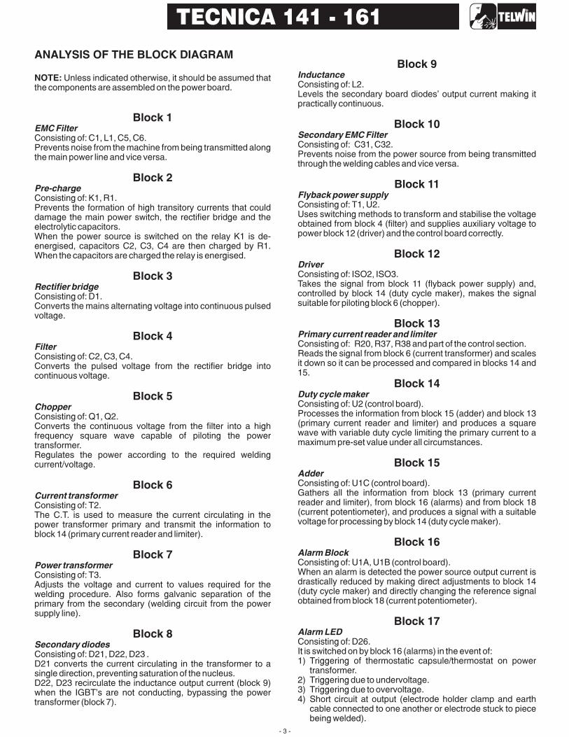
ANALYSIS OF THE BLOCK DIAGRAM
Block 1
Block 2
Block 3
Block 4
Block 5
Block 6
Block 7
Block 8
NOTE: Unless indicated otherwise, it should be assumed thatthe components are assembled on the power board.
Consisting of: C1, L1, C5, C6.Prevents noise from the machine from being transmitted alongthe main power line and vice versa.
Consisting of: K1, R1.Prevents the formation of high transitory currents that coulddamage the main power switch, the rectifier bridge and theelectrolytic capacitors.When the power source is switched on the relay K1 is de-energised, capacitors C2, C3, C4 are then charged by R1.When the capacitors are charged the relay is energised.
Consisting of: D1.Converts the mains alternating voltage into continuous pulsedvoltage.
Consisting of: C2, C3, C4.Converts the pulsed voltage from the rectifier bridge intocontinuous voltage.
Consisting of: Q1, Q2.Converts the continuous voltage from the filter into a highfrequency square wave capable of piloting the powertransformer.Regulates the power according to the required weldingcurrent/voltage.
Consisting of: T2.The C.T. is used to measure the current circulating in thepower transformer primary and transmit the information toblock 14 (primary current reader and limiter).
Consisting of: T3.Adjusts the voltage and current to values required for thewelding procedure. Also forms galvanic separation of theprimary from the secondary (welding circuit from the powersupply line).
Consisting of: D21, D22, D23 .D21 converts the current circulating in the transformer to asingle direction, preventing saturation of the nucleus.D22, D23 recirculate the inductance output current (block 9)when the IGBT's are not conducting, bypassing the powertransformer (block 7).
EMC Filter
Pre-charge
Rectifier bridge
Filter
Chopper
Current transformer
Power transformer
Secondary diodes
Block 9
Block 10
Block 11
Block 12
Block 13
Block 14
Block 15
Block 16
Block 17
Inductance
Secondary EMC Filter
Flyback power supply
Driver
Primary current reader and limiter
Duty cycle maker
Adder
Alarm Block
Alarm LED
Consisting of: L2.Levels the secondary board diodes’ output current making itpractically continuous.
Consisting of: C31, C32.Prevents noise from the power source from being transmittedthrough the welding cables and vice versa.
Consisting of: T1, U2.Uses switching methods to transform and stabilise the voltageobtained from block 4 (filter) and supplies auxiliary voltage topower block 12 (driver) and the control board correctly.
Consisting of: ISO2, ISO3.Takes the signal from block 11 (flyback power supply) and,controlled by block 14 (duty cycle maker), makes the signalsuitable for piloting block 6 (chopper).
Consisting of: R20, R37, R38 and part of the control section.Reads the signal from block 6 (current transformer) and scalesit down so it can be processed and compared in blocks 14 and15.
Consisting of: U2 (control board).Processes the information from block 15 (adder) and block 13(primary current reader and limiter) and produces a squarewave with variable duty cycle limiting the primary current to amaximum pre-set value under all circumstances.
Consisting of: U1C (control board).Gathers all the information from block 13 (primary currentreader and limiter), from block 16 (alarms) and from block 18(current potentiometer), and produces a signal with a suitablevoltage for processing by block 14 (duty cycle maker).
Consisting of: U1A, U1B (control board).When an alarm is detected the power source output current isdrastically reduced by making direct adjustments to block 14(duty cycle maker) and directly changing the reference signalobtained from block 18 (current potentiometer).
Consisting of: D26.It is switched on by block 16 (alarms) in the event of:1) Triggering of thermostatic capsule/thermostat on power
transformer.2) Triggering due to undervoltage.3) Triggering due to overvoltage.4) Short circuit at output (electrode holder clamp and earth
cable connected to one another or electrode stuck to piecebeing welded).
TECNICA 141 - 161

- 4 -
TECNICA 141 - 161
Block 18
Block 19
Block 20
Block 21
Block 22
Block 23
Block 24
Block 25
Current potentiometer
Maximum current adjustment
Power transformer thermostat
Galvanic separator
Overvoltage safeguard
Undervoltage safeguard
Power supply LED
Fan
Consisting of: R7.This is used to set the reference voltage needed to adjust theoutput current: when the potentiometer knob is turned thecursor voltage varies, thus varying the current from theminimum to the maximum value.
Consisting of: R32, R33, R42.Used to adjust the maximum cutting current to be supplied bythe power source.
Consisting of: ST1.When the temperature of the power transformer is too high,this safeguard is triggered. It is reset automatically after thealarm condition has ceased.
Consisting of: ISO1.The signal arriving from block 20 (power transformerthermostat) is separated galvanically and sent to block 16(alarms) for detection of a possible alarm event.
Consisting of: R3, R4 and part of the control section.If the main supply voltage exceeds the maximum value thissafeguard triggers (a tolerance of approx. ±15% of the powersupply voltage is allowed: outside this range the safeguardtriggers).
Consisting of: R5, R6 and part of control board.If the main supply voltage falls below the minimum allowedvalue this safeguard triggers (a tolerance of approx. ±15% ofthe power supply voltage is allowed: outside this range thesafeguard triggers).
Consisting of: D2.Indicates when the power source is correctly powered andready for use.
Consisting of: V1.Powered directly by block 11 (flyback transformer) and coolsthe power components.
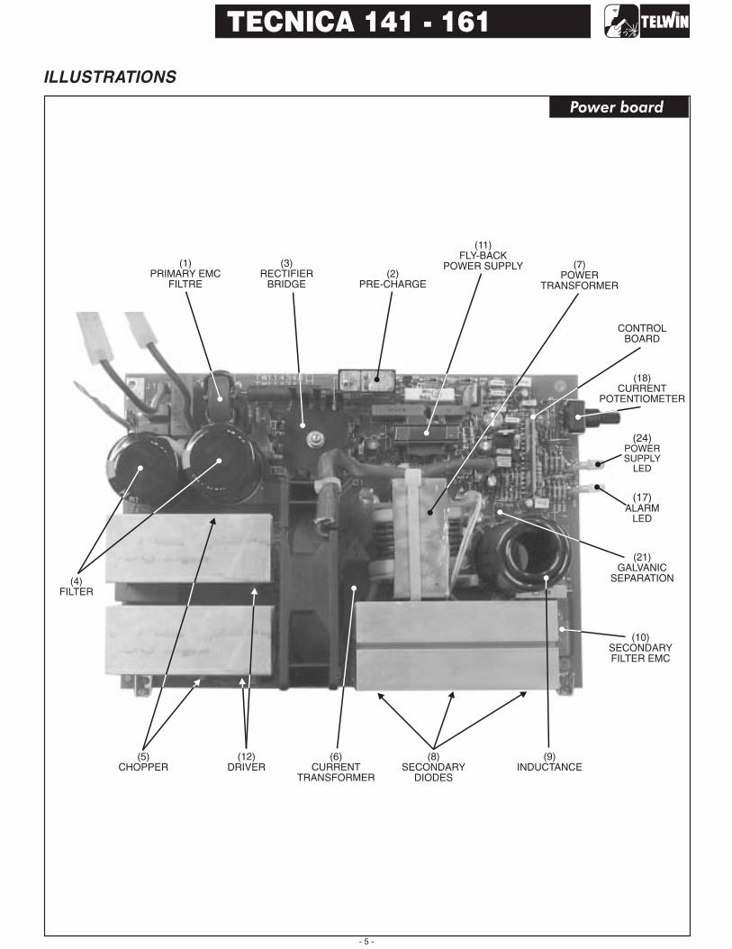
- 5 -
TECNICA 141 - 161
(12)DRIVER
(5)CHOPPER
(3)RECTIFIER
BRIDGE
(11)FLY-BACK
POWER SUPPLY
CONTROLBOARD
(4)FILTER
(1)PRIMARY EMC
FILTRE
(7)POWER
TRANSFORMER
(10)SECONDARYFILTER EMC
(8)SECONDARY
DIODES
(2)PRE-CHARGE
(18)CURRENT
POTENTIOMETER
(24)POWERSUPPLY
LED
(17)ALARM
LED
(9)INDUCTANCE
(21)GALVANIC
SEPARATION
(6)
TRANSFORMERCURRENT
ILLUSTRATIONS
Power board

- 6 -
TECNICA 141 - 161
WIRING DIAGRAMS
General wiring diagram

- 7 -
TECNICA 141 - 161
Wiring diagram for power – power supply/control board
- 8 -
TECNICA 141 - 161
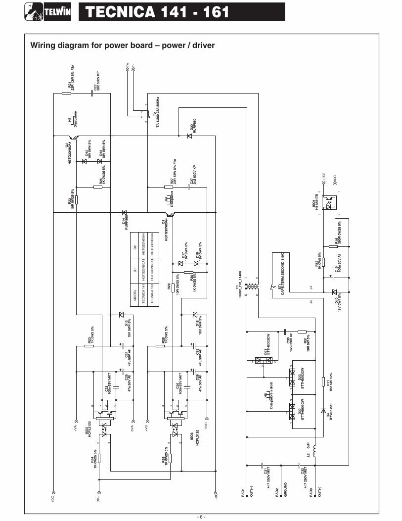
Wiring diagram for power board – power / driver

TECNICA 141 - 161
- 9 -
Wiring diagram for control board

4 2 51 3
6
- 10 -
TECNICA 141 - 161
REPAIR GUIDEREPAIR GUIDEREPAIR GUIDEREPAIR GUIDE
EQUIPMENT REQUIRED
(*)The instruments with codes can be supplied by Telwin. The sale price is available on request.
ESSENTIAL INSTRUMENTS
USEFUL INSTRUMENTS
1 Dual trace oscilloscope cod. 802401 (*)2 Static load generator cod. 802110 (*)3 Variac 0 - 300v 1500 VA cod. 802402 (*)4 Digital multimeter
5 Unsoldering station6 Miscellaneous tools
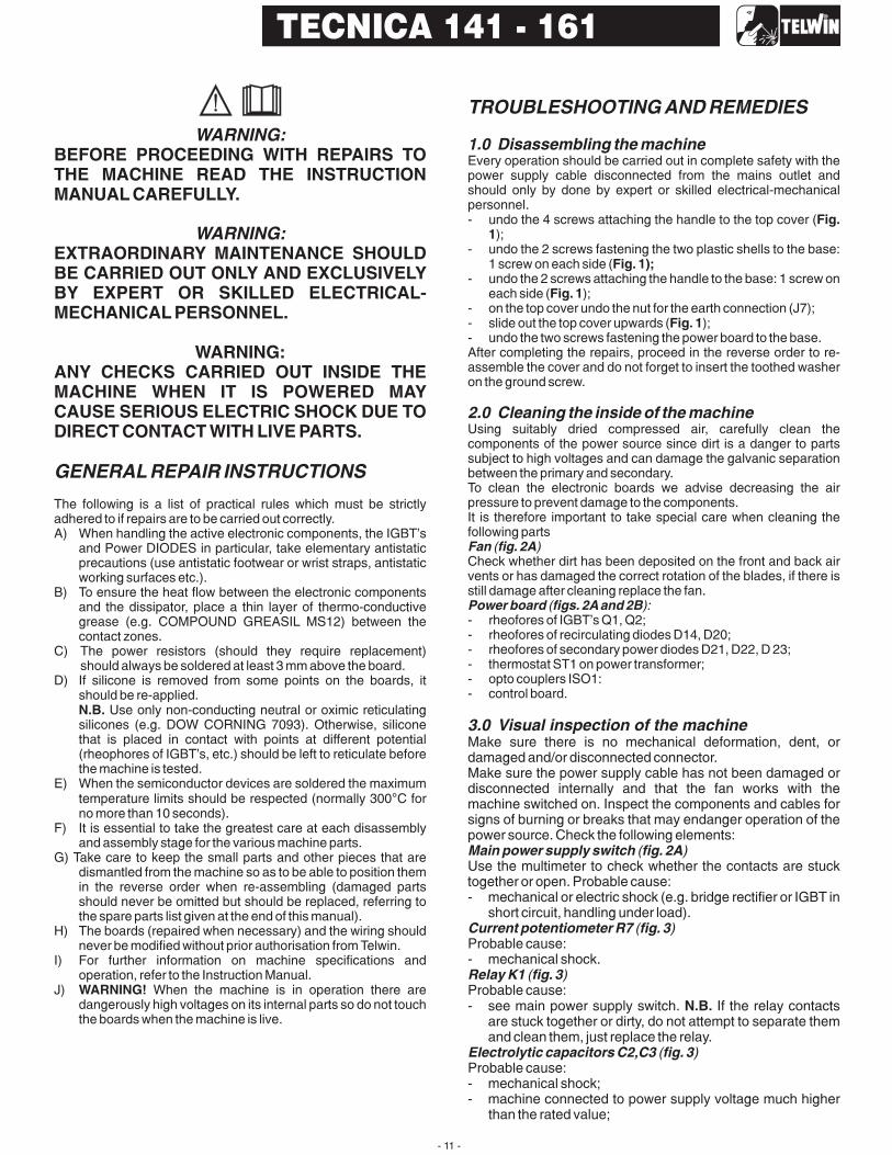
WARNING:
WARNING:
BEFORE PROCEEDING WITH REPAIRS TOTHE MACHINE READ THE INSTRUCTIONMANUAL CAREFULLY.
EXTRAORDINARY MAINTENANCE SHOULDBE CARRIED OUT ONLY AND EXCLUSIVELYBY EXPERT OR SKILLED ELECTRICAL-MECHANICAL PERSONNEL.
WARNING:ANY CHECKS CARRIED OUT INSIDE THEMACHINE WHEN IT IS POWERED MAYCAUSE SERIOUS ELECTRIC SHOCK DUE TODIRECT CONTACT WITH LIVE PARTS.
GENERAL REPAIR INSTRUCTIONS
TROUBLESHOOTING AND REMEDIES
The following is a list of practical rules which must be strictlyadhered to if repairs are to be carried out correctly.A) When handling the active electronic components, the IGBT's
and Power DIODES in particular, take elementary antistaticprecautions (use antistatic footwear or wrist straps, antistaticworking surfaces etc.).
B) To ensure the heat flow between the electronic componentsand the dissipator, place a thin layer of thermo-conductivegrease (e.g. COMPOUND GREASIL MS12) between thecontact zones.
C) The power resistors (should they require replacement)should always be soldered at least 3 mm above the board.
D) If silicone is removed from some points on the boards, itshould be re-applied.
Use only non-conducting neutral or oximic reticulatingsilicones (e.g. DOW CORNING 7093). Otherwise, siliconethat is placed in contact with points at different potential(rheophores of IGBT's, etc.) should be left to reticulate beforethe machine is tested.
E) When the semiconductor devices are soldered the maximumtemperature limits should be respected (normally 300 C forno more than 10 seconds).
F) It is essential to take the greatest care at each disassemblyand assembly stage for the various machine parts.
G) Take care to keep the small parts and other pieces that aredismantled from the machine so as to be able to position themin the reverse order when re-assembling (damaged partsshould never be omitted but should be replaced, referring tothe spare parts list given at the end of this manual).
H) The boards (repaired when necessary) and the wiring shouldnever be modified without prior authorisation from Telwin.
I) For further information on machine specifications andoperation, refer to the Instruction Manual.
J) When the machine is in operation there aredangerously high voltages on its internal parts so do not touchthe boards when the machine is live.
Every operation should be carried out in complete safety with thepower supply cable disconnected from the mains outlet andshould only by done by expert or skilled electrical-mechanicalpersonnel.- undo the 4 screws attaching the handle to the top cover (
);- undo the 2 screws fastening the two plastic shells to the base:
1 screw on each side (- undo the 2 screws attaching the handle to the base: 1 screw on
each side ( );- on the top cover undo the nut for the earth connection (J7);- slide out the top cover upwards ( );- undo the two screws fastening the power board to the base.After completing the repairs, proceed in the reverse order to re-assemble the cover and do not forget to insert the toothed washeron the ground screw.
Using suitably dried compressed air, carefully clean thecomponents of the power source since dirt is a danger to partssubject to high voltages and can damage the galvanic separationbetween the primary and secondary.To clean the electronic boards we advise decreasing the airpressure to prevent damage to the components.It is therefore important to take special care when cleaning thefollowing parts
Check whether dirt has been deposited on the front and back airvents or has damaged the correct rotation of the blades, if there isstill damage after cleaning replace the fan.
- rheofores of IGBT's Q1, Q2;- rheofores of recirculating diodes D14, D20;- rheofores of secondary power diodes D21, D22, D 23;- thermostat ST1 on power transformer;- opto couplers ISO1:- control board.
N.B.
WARNING!
Fig.1
Fig. 1);
Fig. 1
Fig. 1
1.0 Disassembling the machine
2.0 Cleaning the inside of the machine
3.0 Visual inspection of the machine
Fan fig. 2A
Power board figs. 2Aand 2B
( )
( ):
Make sure there is no mechanical deformation, dent, ordamaged and/or disconnected connector.Make sure the power supply cable has not been damaged ordisconnected internally and that the fan works with themachine switched on. Inspect the components and cables forsigns of burning or breaks that may endanger operation of thepower source. Check the following elements:
Use the multimeter to check whether the contacts are stucktogether or open. Probable cause:- mechanical or electric shock (e.g. bridge rectifier or IGBT in
short circuit, handling under load).
Probable cause:- mechanical shock.
Probable cause:- see main power supply switch. If the relay contacts
are stuck together or dirty, do not attempt to separate themand clean them, just replace the relay.
Probable cause:- mechanical shock;- machine connected to power supply voltage much higher
than the rated value;
Main power supply switch fig. 2A
Current potentiometer R7 fig. 3
Relay K1 fig. 3
Electrolytic capacitors C2,C3 fig. 3
( )
( )
( )
( )
N.B.
°
- 11 -
TECNICA 141 - 161

- broken rheophore on one or more capacitor: the remainderwill be overstressed and become damaged byoverheating;
- ageing after a considerable number of working hours;- overheating caused by thermostatic capsule failure.
Probable cause:- discontinuation in snubber network;- fault in driver circuit;- poorly functioning thermal contact between IGBT and
dissipator (e.g. loosened attachment screws: check);- excessive overheating related to faulty operation.
Probable cause:- excessive overheating related to faulty operation.
Probable cause:- discontinuation in snubber network;- poorly functioning thermal contact between IGBT and
dissipator (e.g. loosened attachment screws: check);- faulty output connection.
It is important to check that all the connections are in goodcondition and the connectors are inserted and/or attachedcorrectly. To do this, take the cables between finger and thumb(as close as possible to the fastons or connectors) and pulloutwards gently: the cables should not come away from thefastons or connectors. N.B. If the power cables are not tightenough this could cause dangerous overheating.In particular, on the ( ) it is necessary tocheck the power wiring:
the connection of the power supply cable to the fastons atthe main switch and to the earth faston (J3) on the powerboard;the connections from the power board to the main switch(J1, J2);the connections of the thermostat to the power transformer(ST1);the fan connections (+J5, -J5).
A) With the multimeter set in mode check thefollowing components (junction voltages not less than 0.2V):- rectifier bridge D1 ( );- IGBT's Q1, Q2 (absence of short circuits between
collector-gate and between emitter-collector );- secondary board diodes D21, D22, D23 between anode
and cathode ( ). The secondary diodes can bechecked without removing the power board: with one prodon the secondary board dissipator diodes and the other insequence on the two power transformer outlets;
- viper U2 (absence of short circuits between pin 3 - pin 4and between pin 4 pin 2, )
B) With the multimeter set in ohm mode check the followingcomponents:- resistor R1: 47ohm (pre-charge );- resistors R21,R27: 22ohm (primary snubber );- resistor R31: 10ohm (secondary snubber );- thermostat continuity test on the power transformer: clean
the resin from the bump contacts of ST1 and measure theresistance between the two bump contacts, it should beapprox. 0 ohm ( ).
Before proceeding with faultfinding, we shouldremind you that during these tests the power source ispowered and therefore the operator is exposed to the danger ofelectric shock.The tests described below can be used to check the operationof the power and control parts of the power source.
B) Set up the multimeter in DC mode and connect the prods tothe OUT+ and OUT- bump contacts.C) Position the potentiometer R42 on maximum (turnclockwise as far as it will go).D) Connect the power supply cable to a single-phase variacwith variable output 0-300 Vac.
Switch on the variac (initially set to the value 0 V), switch offthe main switch on the power source and increase the variacvoltage gradually to 230 Vac and make sure:- the green power supply LED D2 lights up ( ),- the fan for the power transformer starts up correctly,- the pre-charge relay K1 commutes ( ),- for voltages close to the rated power supply value (230Vac
±15%) the power source is not in alarm status (yellow LEDD26 off).
if the power source stays in alarm status permanently,there could be a fault in the control board (in any case, proceedto make the other tests)B)
if no signal is present, it may be necessary to replace theintegrated circuit U2 ( ).C) With the multimeter set in mode make sure that( ):- the voltage between connector J9 (-) and the cathode of
diode D32 (+) is equal to +13V ±5% ( );±±±
- the voltage over the ends of capacitor C10 is equal to +29V±5%;
- the voltage over the ends of capacitor C13 is equal to +29V±5%.
IGBT's Q1, Q2 fig. 4
Primary diodes D14, D20 fig. 4
Secondary diodes D21, D22, D23 fig. 4
Power transformer and filter reactance (fig. 2A)
6.1 Preparation for testing
6.2 Tests for the TECNICA141
( )
( )
( )
4.0 Checking the power and signal wiring
5.0 Electrical measurements with the machineswitched off
6.0 Electrical measurements with the machine inoperation
power board fig. 2A
Other checks:
diode testing
fig. 3
fig. 4
fig. 4
fig. 3 .
fig. 3fig. 3
fig. 3
fig. 2B
WARNING!
A)
fig. 3
fig. 3
NB.
N.B.fig. 3
voltfig. 3
fig. 3
-
-
-
-
Make sure that the connections to the (+) and (-) dinse sockets areattached correctly to the power board ( ).
A) Set up the oscilloscope with the voltage probe x100 connectedbetween pin 3 of U2 (probe) and the case of U1 (earth) on thepower board ( ).
Make sure the waveform shown on the oscilloscope resembles.
- the voltage over pin 2 of U2 the earth is equal to +13V 5%;- the voltage over pin 1 and pin 2 of U1 is equal to +18V 3%;- the voltage over pin 3 and pin 2 of U1 is equal to +15V 3%;
Fig. 2B
Fig. 3
Fig. A
- 12 -
TECNICA 141 - 161
FIGURE A
SETTINGS CH1:
· PROBE x100;
· 100 V/Div;
· 5 sec/Div.
· :
65KHz ±10%.
· AMPLITUDE IS:
450V ±10%.
µ
VERIFY THAT:
THE FREQUENCY IS

D) Set up the dual trace oscilloscope. Connect the probeCH1(x100) to the Q1 collector and probe CH2(x10) to the gate,also of Q1. The earth connections are both made to the emitterof Q1.E) Make sure the waveform displayed on the oscilloscoperesembles
F) Repeat this test on Q2 as well using the differential probe.if the signal is not present, there may be a fault in the IGBT
driver circuit ( ) or the control board ( in the lattercase, we recommend replacing the board).G)
H) Make sure the waveform displayed on the oscilloscoperesembles and that the output voltage over OUT+ andOUT - is equal to +85Vdc±10%.
I) Switch the power source on again and make sure that,following the brief start up time, the machine is not in alarmstatus (the yellow alarm LED D26 is off, ). If themachine remains in alarm status (and this is not due to a fault inthe control board) there could be a fault in the photocouplerISO1 ( ).
In this case the tests are just the same as for theTecnica 141 and can be carried out in the same way.
If the fault is in the power board remove it from the bottom asfollows:- with the machine disconnected from the main supply,
disconnect all the wiring connected to the board;- remove the current adjustment knob on the front panel of
the machine ( );- remove any bands constraining the board (e.g. on the
power supply cable and connections to primary);- from the welding side undo the two screws fastening the
dinse sockets to the printed circuit board ( ).- undo the 2 screws fastening the board to the bottom (
).- undo the 2 screws fastening the board to the front and back
on the inside ( ).- after removing the screws, lift the board upwards to remove
it from the bottom of the machine.to re-assemble, proceed in the reverse order,
remembering to insert the toothed washers on the earthscrews.
The 2 IGBT's are attached to 2 different dissipators andwhenever a replacement is required, both IGBT's should bereplaced.- undo the screws attaching the dissipator to the board to
replace Q1.( );- undo the screws attaching the dissipator to the board to
replace Q2 ( );- remove the 2 IGBT's Q1,Q2 and the 2 diodes D20, D14 by
unsoldering the rheofores and then clean the solder fromthe printed circuit bump contacts;
- remove the 2 dissipators from the board;- undo the screws locking the 2 IGBT's.Before making the replacement make sure the componentspiloting the IGBT's are not also damaged:- with the multimeter set in mode make sure there is no
short circuit on the PCB between the 1 and 3 bumpcontacts (between gate and emitter) corresponding to eachcomponent;
- alternatively, resistors R22 and R29 could have burstand/or diodes D12, D15, D17 and D19 may be unable tofunction at the correct Zener voltage (this should haveshown up in the preliminary tests);
- clean any irregularity or dirt from the dissipators. If theIGBT's have burst the dissipators may have beenirreversibly damaged: in this case they should be replaced;
- apply thermo-conductive grease following the generalinstructions.- Insert the new IGBT's between the dissipatorand the spring, taking care not to damage the componentduring assembly (the spring should be inserted underpressure on the dissipator so as to lock the component);
- place the dissipators with the new IGBT's and primary
fig. B.
N.B.fig. 4 fig. 3,
fig. C
fig. 3 N.B.
fig. 3
WARNING!
fig. 1
fig. 2Bfig.
2B
fig. 2B
N.B.
A) Please read the procedure for replacing the IGBT'scarefully: (fig. 4).
fig. 2B
fig. 2B
ohm
Set up the dual trace oscilloscope. Connect probe CH1 (x100)to the collector of Q1 and probe CH2 (x10) to pin 9 on strip J6. Theearth terminals are connected together to the emitter of Q1.
6.3 Tests for the TECNICA161
7.1 Removing the power board fig. 2A( )
st rd
7.0 Repairs, replacing the boardsIf repairing the board is complicated or impossible, it should becompletely replaced. The board is identified by a 6-digit code(printed in white on the component side after the initials TW).This is the reference code for requesting a replacement: Telwinmay supply boards that are compatible but with differentcodes.
before inserting a new board check it carefully fordamage that may have occurred in transit. When we supply aboard it has already been tested and so if the fault is stillpresent after it has been replaced correctly, check the othermachine components. Unless specifically required by theprocedure, never alter the board trimmers.
Warning:
- 13 -
TECNICA 141 - 161
SETTINGS:
· PROBE CH1 x100;
· 100 V/Div;
· PROBE CH2 x10;
· 10V/Div;
· 5 sec/Div.
TIME TOLLERANCES:
±20%.
· AMPLITUDE CH1 IS
320V ±10%;
· POSITIVE
AMPLITUDE CH2 IS
+16V ±10%;
· NEGATIVE
AMPLITUDE CH2 IS
-10V ±10%.
µ
VERIFY THAT
FIGURE B
SETTINGS:
· PROBE CH1 x 100
· 100V/Div;
· PROBE CH2 x10;
· 500mV/Div;
· 5 sec/Div.
TOLERANCES:
· FOR TIME 20%.
PEAK AMPLITUDE CH1:
· 320V 10%.
PEAK AMPLITUDE CH2:
· 500mV 10%.
FIGURE C
diodes D14 and D20 ( Make sure there isinsulation between the case of diode D20 and thedissipator) in the PCB bump contacts, placing 4 spacersbetween the dissipator and the PCB (2 for each dissipator)and fasten them down with the screws (torque wrenchsetting for screws 1 Nm ±20%);
- solder the terminals taking care not to let the solder runalong them;
- on the welding side cut away the protruding part of therheofores and check they are not shorted (between thegate and emitter in particular).
The 3 SECONDARY DIODES are attached to the samedissipator, and when a replacement is required, all of themshould be replaced:- undo the screws attaching the dissipator to the board, to
replace diodes D21, D22 and D23;- remove the 3 secondary diodes unsoldering the rheofores
and cleaning any solder from the bump contacts on theboard;
- remove the dissipator from the board;- remove the spring locking the 3 diodes;- clean any irregularity or dirt from the dissipator. If the diodes
have burst the dissipator may have been irreversiblydamaged: in this case it should be replaced;
- apply thermo-conductive grease following the generalinstructions;
- insert the new diodes between the dissipator and thespring, taking care not to damage the component duringassembly (the screw should be inserted under pressure onthe dissipator so as to lock the component);
- place the dissipator with the new components in the PCBbump contacts and fasten them down with the screws(torque wrench setting for screws 1 Nm ±20%);
- solder the terminals taking care not to let the solder runalong them;
- on the soldering side cut away the protruding part of therheofores and check they are not shorted (betweencathode and anode);
make sure resistor (R31) and capacitor (C30) on thesnubber have been soldered to the PCB correctly ( ).
Whatever fault occurs in the control board, we stronglyrecommend its replacement without attempts at repair. Toremove it, cut and then unsolder from the power board theconnector keeping it fixed perpendicular to the PCB, replace itand re-solder the connector.
Tests should be carried out on the assembled machine beforeclosing it with the top cover. During tests with the machine inoperation never commute the selectors or activate the ohmicload contactor.
Before proceeding to test the machine, we shouldremind you that during these tests the power source ispowered and therefore the operator is exposed to the dangerof electric shock.The tests given below are used to verify power sourceoperation under load.
.A) Connect the power source to the static load generatorusing cables fitted with the appropriate dinse connectors (code802110).
B)
C) Set up the multimeter in DC mode and connect the prods tothe OUT+ and OUT- bump contacts.D) Connect the power supply cable to the 230Vac powersupply.
During tests the operator must avoid contact withthe metal parts of the torch because of the presence ofdangerous, high voltage.
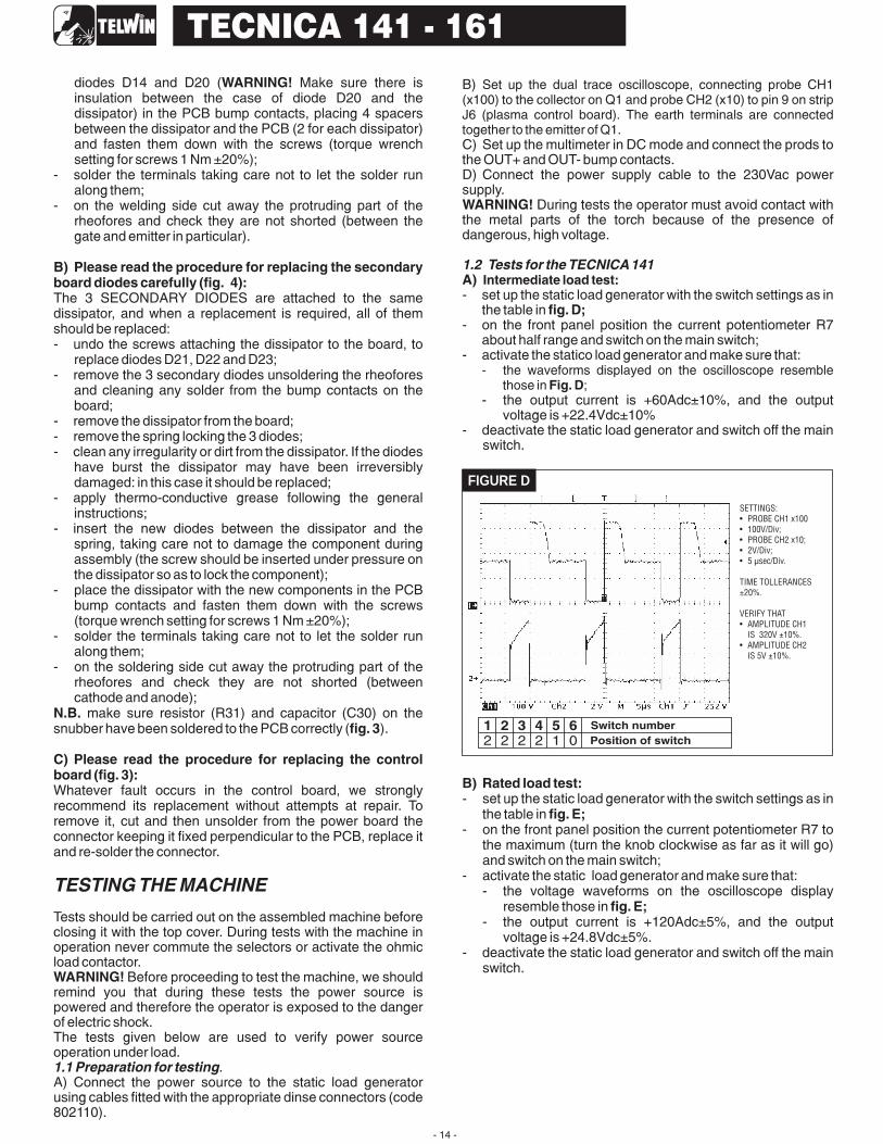
- set up the static load generator with the switch settings as inthe table in
- on the front panel position the current potentiometer R7about half range and switch on the main switch;
- activate the statico load generator and make sure that:
- the output current is +60Adc±10%, and the outputvoltage is +22.4Vdc±10%
- deactivate the static load generator and switch off the mainswitch.
- set up the static load generator with the switch settings as inthe table in
- on the front panel position the current potentiometer R7 tothe maximum (turn the knob clockwise as far as it will go)and switch on the main switch;
- activate the static load generator and make sure that:- the voltage waveforms on the oscilloscope display
resemble those in- the output current is +120Adc±5%, and the output
voltage is +24.8Vdc±5%.- deactivate the static load generator and switch off the main
switch.
WARNING!
B) Please read the procedure for replacing the secondaryboard diodes carefully (fig. 4):
N.B.fig. 3
C) Please read the procedure for replacing the controlboard (fig. 3):
WARNING!
WARNING!
A)
fig. D;
B) Rated load test:
fig. E;
fig. E;
1.1 Preparation for testing
1.2 Tests for the TECNICA141
Set up the dual trace oscilloscope, connecting probe CH1(x100) to the collector on Q1 and probe CH2 (x10) to pin 9 on stripJ6 (plasma control board). The earth terminals are connectedtogether to the emitter of Q1.
- the waveforms displayed on the oscilloscope resemblethose in ;
Intermediate load test:
Fig. D
TESTING THE MACHINE
- 14 -
TECNICA 141 - 161
SETTINGS:
· PROBE
· 100V/Div;
· PROBE CH2 x10;
· 2V/Div;
· 5 sec/Div.
TIME TOLLERANCES
±20%.
· AMPLITUDE CH1
IS 320V ±10%.
· AMPLITUDE CH2
IS 5V ±10%.
CH1 x100
VERIFY THAT
µ
FIGURE D
Position of switch
Switch number12
22
32
42
51
60

C) Checking the secondary diode voltages:
fig. E;
fig. F;
D) Running time check and closing the machinefig. E
E)
point B) point A)points C) D) fig. E
fig. G
A) Rated load test:
fig. G;
fig. G;
B) Running time check and closing the machinefig. G
- set up the dual trace oscilloscope, connecting probe CH1 x100 to the anode of diode D21 and probe CH2x100 to theanode of diode D22. Earth connections are both made tothe secondary dissipator;
- remove the multimeter from the OUT+ and OUT- bumpcontacts;
- set up the static load generator with the switch settings asin the table in
- on the front panel position the current potentiometer R7 tothe maximum (turn the knob clockwise as far as it will go)and switch on the main switch;
- activate the static load generator and make sure that thewaveforms displayed on the oscilloscope resemble thosein
- deactivate the static load generator and switch off the mainswitch.
With the load status as in and the current adjustmentpotentiometer (R7) on maximum, switch on the power sourceand leave it in operation until the thermostatic capsules trigger(machine in alarm status). Check the correct positioning of theinternal wiring and finally re-assemble the machine.
In this case the tests are exactly the same as for the Tecnica141 and can be carried out in the same way with the exceptionof the following points in section 1.2:- replace with in section 1.3);- in and replace the load in with the load
given in in section 1.3.
- set up the static load generator with the switch settings as inthe table in
- on the front panel position the current potentiometer R7 tothe maximum (turn the knob clockwise as far as it will go)and switch on the main switch;
- activate the static load generator and make sure that:- the voltage waveforms on the oscilloscope display
resemble those in- the output current is +150Adc±5%, and the output
voltage is +26Vdc±5%.- deactivate the static load generator and switch off the main
switch.
With the load status as in and the cutting currentadjustment potentiometer (R42) on maximum, switch on thepower source and leave it in operation until the thermostaticcapsules trigger (machine in alarm status). Check the correctpositioning of the internal wiring and finally re-assemble themachine.
Welding testWith the power source set up according to the instructions in thehandbook make a test weld at 80A (electrode diameter 2.5 mm).Check the dynamic behaviour of the power source.
1.3 Tests for the TECNICA141
- 15 -
TECNICA 141 - 161
SETTINGS:
· PROBE
· 50V/Div
· PROBE CH2 x100;
· 50V/Div;
· 5 sec/Div.
TIME TOLLERANCES
±20%.
REVERSE AMPLITUDE
ON CH1 E CH2
CH1 x100;
VERIFICARE CHE:
250V.
VERIFY THAT:
DOES
NOT EXCEED
µ
FIGURE F
SETTINGS:
· PROBE
· 100V/Div;
· PROBE CH2 x10;
· 5V/Div;
· 5 sec/Div.
TIME TOLLERANCES
±20%.
· AMPLITUDE CH1
IS
· AMPLITUDE CH2
IS
CH1 x100
320V ±10%;
10V ±10%.
VERIFY THAT
µ
FIGURE E
13
23
32
42
52
62 Position of switch
Switch number
13
23
33
43
52
61
SETTINGS:
· PROBE
· 100V/Div;
· PROBE CH2 x10;
· 5V/Div;
· 5 sec/Div.
TIME TOLLERANCES
±20%.
· AMPLITUDE CH1
IS
· AMPLITUDE CH2
IS
CH1 x100
320V ±10%;
10V ±10%.
VERIFY THAT
µ
FIGURE G
Position of switch
Switch number
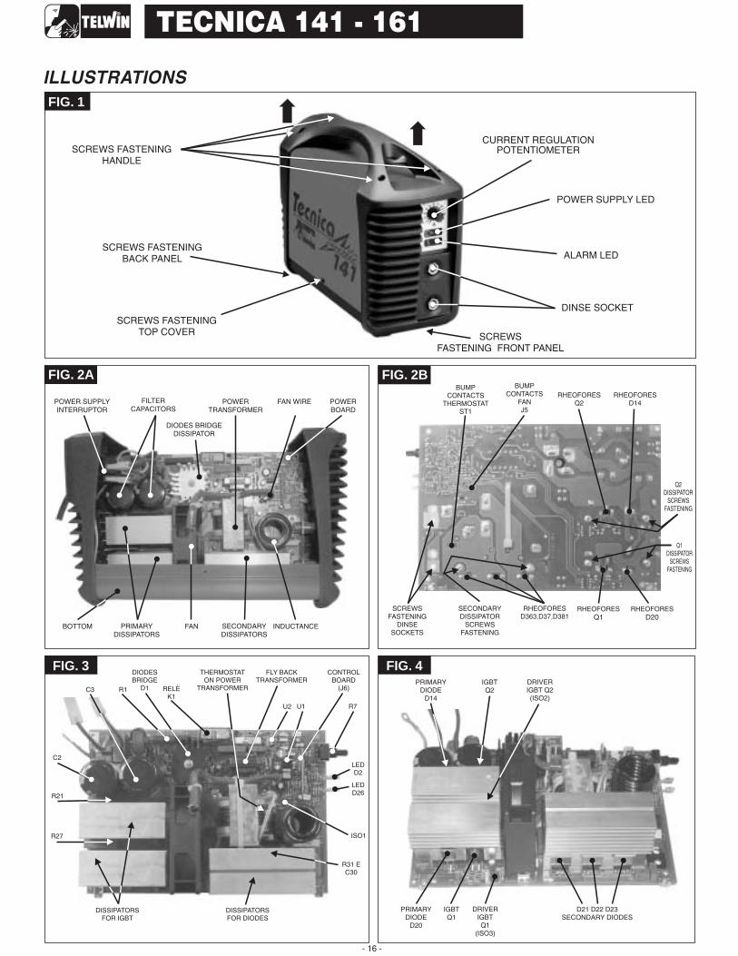
FIG. 1
SCREWS FASTENINGTOP COVER
POWER SUPPLY LED
CURRENT REGULATIONPOTENTIOMETER
POWERTRANSFORMER
SECONDARYDISSIPATORS
POWER SUPPLYINTERRUPTOR
FAN WIRE POWERBOARD
BOTTOM INDUCTANCEFAN
BUMPCONTACTS
THERMOSTATST1
RHEOFORESQ2
RHEOFORESD14
Q2DISSIPATOR
SCREWSFASTENING
SCREWSFASTENING
DINSESOCKETS
Q1DISSIPATOR
SCREWSFASTENING
SECONDARYDISSIPATOR
SCREWSFASTENING
RHEOFORESD363,D37,D381
FIG. 2A FIG. 2B
FIG. 4PRIMARY
DIODED14
PRIMARYDIODE
D20
IGBTQ1
DRIVERIGBTQ1
(ISO3)
D21 D22 D23SECONDARY DIODES
IGBTQ2
DRIVERIGBT Q2(ISO2)
RHEOFORESQ1
RHEOFORESD20
- 16 -
TECNICA 141 - 161
ALARM LED
SCREWSFASTENING FRONT PANEL
SCREWS FASTENINGBACK PANEL
FILTERCAPACITORS
FIG. 3
C2
C3 R1
U2
DIODESBRIDGE
D1 RELÈK1
CONTROLBOARD
(J6)
U1 R7
LEDD2
ISO1
R31 EC30
DISSIPATORSFOR DIODES
DISSIPATORSFOR IGBT
R27
R21
FLY BACKTRANSFORMER
THERMOSTATON POWER
TRANSFORMER
LEDD26
BUMPCONTACTS
FANJ5
SCREWS FASTENINGHANDLE
DINSE SOCKET
PRIMARYDISSIPATORS
ILLUSTRATIONS
DIODES BRIDGEDISSIPATOR

ELENCO PEZZI DI RICAMBIO - LISTE PIECES DETACHEESSPARE PARTS LIST - ERSATZTEILLISTE - PIEZAS DE REPUESTO
Per richiedere i pezzi di ricambio senza codice precisare: codice del modello; il numero di matricola; numero di riferimento del particolare sull'elenco ricambi.Pour avoir les pieces detachees, dont manque la reference, il faudra preciser: modele, logo et tension de I'appareil; denomination de la piece; numero de matricule
When requesting spare parts without any reference, pls specify: model-brand and voltage of machine; list reference number of the item; registration numberWenn Sie einen Ersatzteil, der ohne Artikel Nummer ist, benoetigen, bestimmen Sie bitte Folgendes: Modell-zeichen und Spannung des Geraetes; Teilliste Nuemmer; Registriernummer
Por pedir una pieza de repuesto sin referencia precisar: modelo-marca e tension de la maquina; numero di riferimento de lista; numero di matricula
- 17 -
TECNICA 141 - 161
Esploso macchina, Dessin appareil, Machine drawing, Explosions Zeichnung des Geräts, Diseño seccionado maquina.
1
13
8
6
10
15
12 2 25 14 24
11 4
5
17
22
7
16
20
21
18
3 23
19

- 18 -
TECNICA 141 - 161
ELENCO PEZZI DI RICAMBIOPIECES DETACHEESSPARE PARTS LISTERSATZTEILLISTE
PIEZAS DE REPUESTO
ELENCO PEZZI DI RICAMBIOPIECES DETACHEESSPARE PARTS LISTERSATZTEILLISTE
PIEZAS DE REPUESTO
ELENCO PEZZI DI RICAMBIOPIECES DETACHEESSPARE PARTS LISTERSATZTEILLISTE
PIEZAS DE REPUESTO
ELENCO PEZZI DI RICAMBIOPIECES DETACHEESSPARE PARTS LISTERSATZTEILLISTE
PIEZAS DE REPUESTO
ELENCO PEZZI DI RICAMBIOPIECES DETACHEESSPARE PARTS LISTERSATZTEILLISTE
PIEZAS DE REPUESTO
REF. REF. REF. REF. REF.
PotenziometroPotentiometrePotentiometerPotentiometerPotenciometroResistenzaResistanceResistorWiederstandResistenciaRele'RelaisRelaisRelaisRelaisDiodoDiodeDiodeDiodeDiodoCondensatoreCondensateurCapacitorKondensatorCondensadorRaddrizzatoreRedresseurRectifierGleichrichterRectificadorManopola PotenziometroPoignee Pour PotentiometreKnob For PotentiometerPotentiometergriffMalja Por Resist.electr.variableInterruttoreInterrupteurSwitchSchalterInterruptor
1
2
3
4
5
6
7
8
10
11
12
13
14
15
16
17
18
19
20
21
22
23
24
25
Cavo Alim.Cable Alim.Mains CableNetzkabelCable Alim.VentilatoreVentilateurFanVentilatorVentiladorInduttanza FiltroInductance FilterFilter InductanceFilter DrosselInduccion FiltroInduttanzaInductanceInductanceDrosselInduccionTrasformatore FlybackTransformateur FlybackFlyback TransformerFlyback TransformatorTransformador FlybackFondoChassisBottomBodenteilFondoPresa DinsePrise DixDinse SocketDinse SteckdoseEnchufe DinseKit Igbt + DiodoKit Igbt + DiodeKit Igbt + DiodeKit Igbt + DiodeKit Igbt + Diodo
Kit MantelloKit CapotCover KitDeckel KitKit Panel De CoberturaKit Scheda CompletaKit Platine CompleteKit Complete PcbKit Komplette SteurungskarteKit Tarjeta CompletaFrontalePartie FrontalFront PanelGeraetefrontFrontalRetroPartie ArriereBack PanelRueckseiteTraseraManigliaPoigneeHandleHandgriffManijaPwm ControllerPwm ControllerPwm ControllerPwm ControllerPwm ControllerScheda ControlloPlatine De ControlControl PcbSteurungskarteTarjeta De ControloTrasformatore potenzaTransformateur PuissancePower TransformerLeistungstransformatorTransformador De Potencia
TECHNICAL REPAIR CARD.In order to improve the service, each servicing centre is requested to fill in the technical card on the following page at the end of every repairjob. Please fill in this sheet as accurately as possible and send it to Telwin. Thank you in advance for your co-operation!

- 19 -
TECNICA 141 - 161
Official servicing centersRepairing sheet
Date:
Inverter :
Serial number:
Company:
Technician:
model
In which place has the inverter been used?
Building yard
Workshop
Others:
Supply:
Power supply
From mains without extension
:From mains with extension m
Mechanichal stresses the machine has undergone to
cription:Des
Dirty grade
Dirty inside the machine
Description:
Rectifier bridge
Electrolytic capacitors
Relais
In-rush limiter resistance
IGBT
Snubber
Secondary diodes
Potentiometer
Others
Kind of failure Component ref.Substitution of primary power board: yes no
Troubles evinced during repair :

TELWIN S.p.A.
800 801
- Via della Tecnica, 336030 VILLAVERLA (Vicenza) ItalyTel. +39 - 0445 - 858811Fax +39 - 0445 - 858 / 858E-mail: [email protected] http://www.telwin.com