Embed Size (px)
Citation preview

16010856
Gwynt Y Mor
Ex-AnteTechnical Review
London, Sept 28, 2012 Author(s) C MacKenzie
On behalf of Ofgem E-Serve
author : C MacKenzie reviewed :Alan Aldridge
approved :

16010856
-2-
Disclaimer
Any information provided by DNV KEMA and relating to the technical and cost reviews of relevant
offshore transmission assets will be 'as is', without any representation or endorsement made and without
warranty of any kind whether express or implied, including, but not limited to, the implied warranties of
satisfactory quality, fitness for a particular purpose, security and accuracy, other than as separately
agreed in writing with our Client who has requested us to prepare this report.
The cost reviews will reflect the opinion of DNV KEMA as to the value of the transmission assets if they
had been developed in an economic and efficient manner. The primary source in preparing this opinion
has been information provided by the offshore wind farm developer during the period from August 2012
up and until 21 September 2012 and we have not sought to establish the reliability of the sources by
reference or other evidence. We do not accept responsibility for such information, and the report does not
incorporate the effects, if any, of events and circumstances that may have occurred or information that
may have come to light after said dates. The issues covered in this report, and the emphasis placed on
them, may not address the issues relevant to others than our Client, or reflect their specific requirements,
objectives, interests or circumstances.
The purpose of this opinion is to facilitate the competitive tender process of our Client for the appointment
of offshore transmission licensees only. The opinion will not constitute legal or other professional advice.
Although this report was prepared in good faith, DNV KEMA will not accept any responsibility for the
accuracy, completeness or otherwise of the information. DNV KEMA (including its Directors and
employees) will not accept liability for any loss or damage, howsoever arising, from the use, misuse of or
reliance on this information, including but not limited to any errors, omissions or misleading or inaccurate
statements. In no event will DNV KEMA be liable for any loss or damage including, without limitation,
direct, indirect or consequential loss or damage, or any loss or damages whatsoever arising from use or
misuse of the information.

16010856
-3-
CONTENTS
page
Executive Summary 4
1 Introduction 8
1.1 Background ........................................................................................................... 8
1.2 DNV KEMA Terms of reference .......................................................................... 10
1.2.1 Objective ............................................................................................................. 10
1.2.2 Scope and Approach ........................................................................................... 12
2 Technical review of offshore transmission system 13
2.1 Design philosophy ............................................................................................... 13
2.1.1 Offshore Transmission Network Layout and Design Engineering ........................ 14
2.1.2 Export Cable Design and Rating ......................................................................... 15
2.1.3 Electrical Infrastructure Design and Equipment Rating ........................................ 16
2.1.4 Spare Onshore Transformer Justification ............................................................ 22
2.2 Offshore Transmission Assets Overview ............................................................. 23
2.2.1 Offshore Substations ........................................................................................... 24
2.2.2 Onshore Substation ............................................................................................ 25
2.2.3 Export Cables ..................................................................................................... 25
2.3 Compliance with industry codes and standards ................................................... 26
2.4 Conclusions ........................................................................................................ 26
3 Procurement 28
3.1 Tender for the Electrical Systems Package. ........................................................ 28
3.2 Onshore Cable Supply and Installation Package ................................................. 28
3.3 Offshore Cable Supply Package ......................................................................... 28
3.4 Offshore Cable Installation Package ................................................................... 28
3.5 OSP Jacket Design and Fabrication Package ..................................................... 28
3.6 OSP Jacket Installation ....................................................................................... 29
3.7 OSP Topside Transport and Lift Package ........................................................... 29
3.8 Two 400kV bays unlicensed works contract was placed with NGET. .................. 29
3.9 Installation Progress at beginning of September 2012 ........................................ 29
appendix A – Technical Assessment 31
Appendix A1. Electrical equipment and system design ......................................................... 32
Appendix A2. National Electricity Transmission System Security and Quality of Supply
Standard Compliance Assessment ....................................................................................... 34
Appendix A3. System Operator – Transmission Owner Code Compliance Assessment ....... 38

16010856
-4-
EXECUTIVE SUMMARY
The Gwynt y Mor wind farm will be located 13 to 15 km off the north coast of Wales and covers
an area of approximately 79km2, extending from Penrhyn Bay in the west to Prestatyn in the
east. When complete the wind farm will have a total installed generation capacity of 576MW
and is due to be completed by the end of 2014. The project is being developed by Gwynt y Mor
Offshore Wind Farm Limited (GMOWL) which is owned and financed by three shareholders
under an Unincorporated Joint Venture (“UJV”), namely RWE Innogy (60%), Stadtwerke
Munchen (30%) and Siemens AG (10%). All three shareholders are financing the project on
their respective balance sheets. The project will be engineered, procured, constructed,
operated and maintained by RWE Npower Renewables Ltd, a wholly owned subsidiary of RWE
Innogy (“RWEI”).
The transmission assets proposed for transfer to the Offshore Transmission Owner (OFTO)
comprise two offshore substations each with two 132/33kV transformers, four 132kV export
cable circuits and onshore 132kV and 400kV infrastructure comprising two 400/132kV auto-
transformers plus a spare 400/132kV auto transformer, 132kV and 400kV GIS switchgear,
reactive power compensation and harmonic filtering equipment. The onshore OFTO
infrastructure will connect to National Grid’s new Bodelwyddan 400kV substation near St Asaph.
The OFTO transmission assets are under construction and are due to be completed and
commissioned by the end of 2012/early 2013 ready for commissioning of the first wind turbine in
April/May 2013.
This report provides a technical review of the Gwynt y Mor transmission assets which covers
overall project design philosophy, technical compliance of the proposed offshore infrastructure
with industry codes and standards, procurement process and installation progress to date.
Ofgem has carried out a review of the OFTO connection asset costs provided by GMOWL and
has advised that there are no outlying costs. This being the case Ofgem has no requirement for
a bottom up cost assessment of any of the main component parts of the OFTO assets.
The aim of DNV KEMA's technical review is to establish whether the general design process
and approach followed by GMOWL is reasonable and representative of good practice design,
review the procurement process applied and establish with GMOWL the installation progress.
The review undertaken has considered all relevant technical and procurement information
provided by GMOWL to Ofgem and DNV KEMA, up to and including 14 Sept 2012.
Technical Review of the Gwynt y Mor Offshore Transmission System
The technical review undertaken by DNV KEMA has been based on the selected relevant
project information provided by the developer to Ofgem and DNV KEMA including the GMOWL

16010856
-5-
Information Memorandum and various technical documents available in the GMOWL data room.
In addition, the developer was also asked to respond to questions developed specifically to
seek clarifications and / or explanations and relevant evidence in support of the most important
design and planning issues that arose during project development. It should be noted that
much of the information required for the review was not present in the developer data room and
hence had to be requested.
The high level technical review of the GMOWL Transmission Assets conducted by DNV KEMA
has concluded that GMOWL has adopted and implemented a standard engineering design
process which has been reasonably well documented and can be considered representative of
widespread and good practice design internationally. The engineering design philosophy of the
offshore transmission assets that was carried out by the developer and the design specification
of the related electrical works that was finalised by the preferred contractor for provision of
electrical works, Siemens Transmission and Distribution Ltd (STDL), resulted in a well thought
through and fit for purpose design of the offshore transmission infrastructure.
Based on various relevant design and planning information provided to and reviewed by DNV
KEMA, the following specific observations can be made in relation to the adopted design
process, design philosophy and overall project compliance:
The project overall design engineering process followed a standard well established and
recognised design approach starting with the conceptual design (e.g. consideration of
feasibility options and topologies) and following through with the full technical and
functional specifications and required system studies. Evidence of review meetings at
key stages in the project development has not been established.
The offshore transmission network layout, export cable transmission voltage and ratings
and overall electrical infrastructure design and equipment ratings underwent detailed
analysis in terms of their viability and techno-economic optimisation. As a result, the
design of the proposed offshore transmission infrastructure appears well justified and fit
for purpose.
All relevant offshore equipment has been specified to international or national standards.
Where relevant information has been made available the offshore transmission system
is compliant with the planning criteria and connection requirements specified in industry
framework documents including the National Electricity Transmission System Security
and Quality of Supply Standard (NETS SQSS), System Operator and Transmission
Owner Code (STC) and Grid Code.
Based on various relevant tender assessment reports and contract information provided to and
reviewed by DNV KEMA, the following specific observations can be made in relation to the
adopted procurement process:
GMOWL has adopted a multi-package procurements strategy where the procurement of
each major package followed a strategy of investigating the supply market and then

16010856
-6-
holding a pre-qualification phase. Tenders were then either carried out in one or two
phases to establish the most favourable commercial terms prior to awarding a contract
or appointing a preferred bidder to further develop the scope of work and commercial
terms.
The strategy adopted for the offshore marine export cables was a separate cable supply
and cable installation contract in order to gain the best commercial terms overall.
The GMOWL 400kV bay works at the new NGET Bodelwyddan 400kV substation were
in place with NG as a single tender action.
The offshore substation topside transportation and lift package was to be carried out by
RWE's Seabreeze II jackup vessel which in 2010/2011 was still under construction. The
vessel was expect to be handed over to GMOWL in November 2011, however, the
vessel required substantial remedial works and it was confirmed the vessel would not
be ready until summer 2012. To mitigate delays to the topside installation and other
related packages GMOWL went to the market for the topside transport and lift package.
Maintaining the installation programme meant that only two suitable vessels were
available and GMOWL received bids from both parties, SHL and Scaldis. xxxxxxxxxxx
xxxxxxxxxxxxxxxxxxxxxxxxxxxxxxxxxxxxxxxxxxxxxxxxxxxxxxxxxxxxxxxxxxxxxxxxxxxxx
xxxxxxxxxxxxxxxxxxxxxxxxxxxxxxxxxxxxxxxxxxxxxxxxxxxxxxxxxxxxxxxxxxxxxxxxxxxxx
xxxxxxxxxxxxxxxxxxxxxxxxxxxxxxxxxxxxxxxxxxxxxxxxxxxxxxxxxxxxxxxxxxxxxxxxxxxxx
xxxxxxxxxxxxxxxxxxxxxxxxxxxxxxxxxxxxxxxxxxxxxxxxxxxxxxxxxxxxxxxxxxxxxxxxxxxxx
xxxxxxxxxxxxxxxxxxxxxxxxxxxxxxxxxxxxxxxxxxxxxxxxxxxxxxxxxxxxxxxxxxxxxxxxxxxxx
xxxxxxxxxxxxxxx
Xxxxxxxxxxxxxxxxxxxxxxxxxxxxxxxxxxxxxxxxxxxxxxxxxxxxxxxxxxxxxxxxxxxxxxxxxxxxxx
xxxxxxxxxxxxxxxxxxxxxxxxxxxxxxxxxxxxxxxxxxxxxxxxxxxxxxxxxxxxxxxxxxxxxxxxxxxxx
xxxxxxxxxxxxxxxxxxxxxxxxxxxxxxxxxxxxxxxxxxxxxxxxxxxxxxxxxxxxxxxxxxxxxxxxxxxxx
xxxxxxxxxxxxxxxxxxxxxxxxxxxxxxxxxxxxxxxxxxxxxxxxxxxxxxxxxxxxxxxxxxxxxxxxxxxxx
xxxxxxxxxxxxxxxxxxxxxxxxxxxxxxxxxxxxxxxxxxxxxxxxxxxxxxxxxxxxxxxxxxxxxxxxxxxxx
xxxxxxxxxxxxxxxxxxxxxxxxxxxxxxxxxxxxxxxxxxxxxxxxxxxxxxxxxxxxxxxxxxxxxxxxxxxxx
xxxxxxxxxxxxxxxxxxxxxxxxxxxxxxxxxxxxxxxxxxxxxxxxxxxxxxxxxxxxxxxxxxxxxxxxxxxxx
xxxxxxxxxxxxxxxxxxxxxxxxxxxxxxxxxxxxxxxxxxxxxxxxxxxxxxxxxxxxxxxxxxxxxxxxxxxxx
xxxxxxxxxxxxxxxxxxxxxxxxxxxxxxxxxxxxxxxxxxxxxxxxxxxxxxxxxxxxxxxxxxxxxxxxxxxxx
xxxxxxxxxxxxxxxxxxxxxxxxxxxxxxxxxxxxxxxxxxxxxxxxxxxxxxxxxxxxxxxxxxxxxxxxxxxxx
xxxxxxxxxxxxxxxxxxxxxxxxxxxxxxxxxxxxxxxxxxxxxxxxxxxxxxxxxxxxxxxxxxxxxxxxxxxxx
xxxxxxxxxxxxxxxxxxxxxxxxxxxxxxxxxxxxxxxxxxxxxxxxxxxxxxxxxxxxxxxxxxxxxxxxxxxxx
xxxxxxxxxxxxxxxxxxxxxxxxxxxxxxxxxxxxxxxxxxxxxxxxxxxxxxxxxxxxxxxxxxxxxxxxxxxxx
xxxxxxxxxxxxxxxxxxxxxxxxxxxxxxxxxxxxxxxxxxxxxxxxxxxxxxxxxxxxxxxxxxxxxxxxxxxxx
xxxxxxxxxx
The only substantial design variation after the award of a contract was on STDL's
Electrical System package where an issue with the 29th harmonic voltage distortion is
being addressed by changing the 400kV cables from the two 400/132kV auto

16010856
-7-
transformer to the 400kV switch bays to a larger cross sectional cable to alter the
capacitive characteristic of the 400kV network.

16010856
-8-
1 INTRODUCTION
1.1 Background
The Gwynt y Mor wind farm will be located 13 to 15 km off the north coast of Wales and will
have a total installed wind turbine capacity of 576 MW. The project is being developed by
Gwynt y Mor Offshore Wind Farm Limited (GMOWL) which is owned and financed by three
shareholders, RWE Innogy, Stadtwerke Munchen and Siemens AG.
The wind farm will comprise 160 Siemens Wind Turbine Generators (WTG) each rated at
3.6MW. This turbine type is based on pitch regulated power control and employs an induction
generator which is connected to the grid through a voltage-sourced converter (VSC). Each
turbine is connected to the 33 kV inter-array cable network via a 0.69/33kV step up
transformer1. Two offshore substation platforms (OSP) have been built, each containing two
132/33kV, 160MVA transformers, a two section 33kV bus-bar, 33kV switchgear, and auxiliary
equipment. Each of the offshore grid transformers is directly connected to a 132 kV export
cable. At the onshore substation the four export circuits connect to a 132kV double busbar
substation. Two 400kV/132kV auto transformers which have a 13.9kV tertiary winding connect
the wind farm to the new NGET Bodelwyddan 400 kV substation near St Asaph where GMOWL
own the two 400kV GIS switch bays. The 13.9kV tertiary winding of each super grid transformer
connects an SVC PLUS reactive compensation plant which is a combination of two
mechanically switched capacitors (MSC), two mechanically switched reactors (MSR) and a
static electronic compensator which utilises VSC (Voltage Source Converter) technology and
provides dynamic compensation control. A filter is connected to each of the two sections of the
132kV substation designed to reduce 5th harmonic voltage distortion.
For contingency cases e.g. loss of a 400kV circuit the 132 kV onshore busbar interconnector
can be used to interconnect the two 132 kV busbar sections. If there is a 132kV busbar section
failure then the substation can be reconfigured to utilise the reserve busbar of the double
busbar arrangement to restore the wind farm connection to the 400kV connection point.
Four 132kV cables are used to link the two OSPs (one cable per 132/33kV transformer) to the
132kV onshore substation. The two 132kV export circuits from the East wind farm offshore
1 Details from STDL report "Detailed Load Flow Study SVC PLUS, RWE Doc No. GM01-STDL-0110-EN-001016446-
01, Siemens, dated 8 May 2012, Rev 3".
16010856
-9-
substation connect to one 132kV busbar section with the two 132kV circuits from the West wind
farm offshore substation connecting to the other 132kV busbar. The approximate cable circuit
lengths are:
Platform-to-shore connections consisting of four 132kV cables, two cables from the East
Substation (each 22.4km in length) and two cables from the West Substation (each
19.0km in length), giving a total cable length of 82.8km (subject to final route
engineering). These circuit elements are constructed using 1 x 3core 1000mm2 XLPE
insulated marine cables with aluminium conductors.
The onshore cables link the subsea cables to the onshore 132kV substation. The
onshore connections will consist of 4 underground 132kV circuits, each 11km in length.
These circuit elements are constructed using 3 x 1core 500mm2 XLPE insulated cables
with copper conductors.
The new onshore 132kV substation is located at St Asaph next to the new NGET Bodelwyddan
400kV substation where the two 400kV GIS switch bays form part of the OFTO asset transfer.
The 400kV and 132kV substations are connected by two 400/132kV auto transformers located
at the GMOWL 132kV substation with 400kV cable circuits connecting the auto transformers to
the 400kV GIS switch bays. Reactive compensation in the form of Static Var Compensation
(SVC) units and mechanically switched capacitors and inductors is provided via a tertiary
connection on each auto-transformer. Harmonic filters will also be installed on each of the two
132kV substation busbar sections in order to comply with Engineering Recommendation G5/4-1
harmonic and emission requirements2.
The OFTO ownership 400kV circuit boundaries3 are proposed to be the gas barrier between the
isolator gas zone and the circuit buffer gas zone, GMOWL presently own the zone between the
busbar gas zones and circuit breaker gas zone. The 33kV ownership boundary will be at the
busbar clamps of 33kV circuit breakers (Generator owned) on the LV side of offshore grid
transformers (TX5, TX6, TX7, TX8).
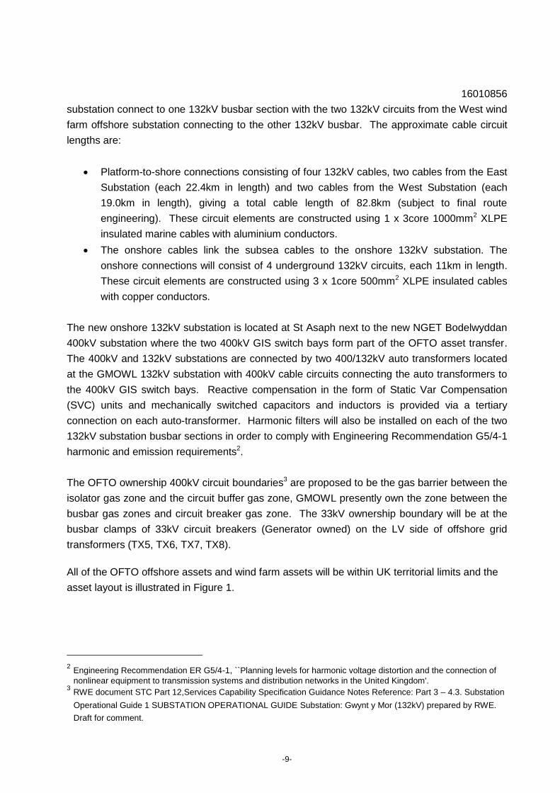
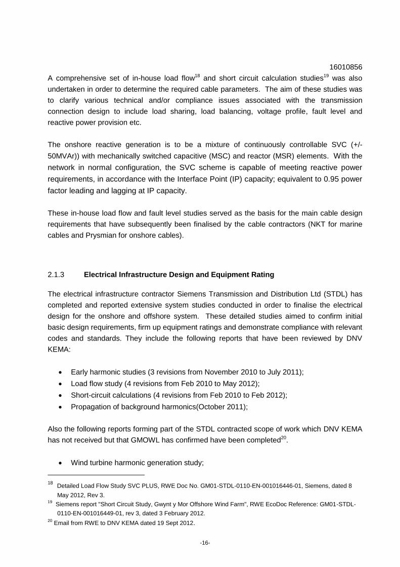
All of the OFTO offshore assets and wind farm assets will be within UK territorial limits and the
asset layout is illustrated in Figure 1.
2 Engineering Recommendation ER G5/4-1, ``Planning levels for harmonic voltage distortion and the connection of
nonlinear equipment to transmission systems and distribution networks in the United Kingdom'. 3 RWE document STC Part 12,Services Capability Specification Guidance Notes Reference: Part 3 – 4.3. Substation
Operational Guide 1 SUBSTATION OPERATIONAL GUIDE Substation: Gwynt y Mor (132kV) prepared by RWE.
Draft for comment.
16010856
-10-
Figure 1: Location of the GMOWL Wind farm (source: Ofgem)
1.2 DNV KEMA Terms of reference
1.2.1 Objective
Ofgem commissioned this technical review in support of its own analysis and assessment on
whether the costs associated with developing and constructing the GMOWL transmission
assets that will transfer to the OFTO are economic and efficient. The review here is intended to
inform Ofgem's decision on the indicative transfer value for the GMOWL transmission assets
that will be set at the Invitation to Tender (ITT) stage of the tender process for Tender Round 2
‘Tranche A’ projects.
The review incorporates the following aspects:
1. Design Philosophy
Offshore transmission network layout and design engineering; including options that
were considered for the design, preferred option and rationale, audit trail for decision
making and influences i.e. connection points, marine cable landing points, external
factors such as planning constraints etc;

16010856
-11-
Export Cable design and rating; documentation to back up the design parameters,
supporting information regarding the cable route as well as consideration of
environmental factors;
Electrical infrastructure design and equipment rating; supporting information e.g.
harmonic studies, redundancy in design, reactive power studies, future operations and
maintenance activities; and
The rationale for the 132/400kV spare transformer.
2. Offshore Transmission Asset Review
Description of the assets including the onshore substation, offshore substations and
export cables, and whether a unique and novel solution was required i.e. driven by
external factors;
Compliance with industry codes e.g. international/national standards and NETS SQSS;
and
Installation progress.
3. Review of GMOWL procurement process
Identify the main contracts and the timeline and chronological overview of the
procurement process;
GMOWL criteria for assessing tenders, decision making factors that influenced choosing
contractors e.g. cost, service etc;
Tender assessment for the transmission assets;
Post contract award, were there any substantial design changes; and
Conclusions on the overall procurement process.
4. Cost Analysis
Where cost outliers are identified, carry out a bottom up cost review.
Ofgem has indicated that there are no cost outliers associated with the Gwynt y Mor assets
to be transferred to the OFTO, hence, no bottom up cost assessments have been carried
out.
For the purpose of this review, various relevant project information provided by the developer to
Ofgem and DNV KEMA is relied upon and includes:
Preliminary Information Memorandum4,
4 Preliminary Information Memorandum, Gwynt e Mor Offshore Transmission Assets, November 2010, Ofgem
Eserve.

16010856
-12-
Relevant project information available in the GMOWL data room including various
technical, commercial and planning documents. It is noted that many of the technical
and tender assessment documents were not available in the data room and were
requested directly from GMOWL.
GMOWL's supporting information provided in response to DNV KEMA's request for
information or clarifications of certain project issues. This included the majority of the
technical documents reviewed.
1.2.2 Scope and Approach
DNV KEMA’s approach for assessing this transitional project has been designed to confirm:
Technical and operational compliance including the project engineering design process,
design philosophy and ‘fit for purpose’ design.
The suitability of the procurement process adopted for the main packages associated
with the assets to be transferred to the OFTO.
Whilst some of the information with respect to technical and procurement data is available in the
GMOWL Information Memorandum5 and data room, it was necessary to obtain more in-depth
knowledge of the engineering design process and design philosophy in particular. This was
achieved by asking the developer to respond to an initial list of questions and information
requests followed by a meeting with key GMOWL team members on 3 September 2012 at
RWE's office in Swindon. From the discussions at this meeting a further list of actions to
address further DNV KEMA questions and data requests was produced. During the writing of
the draft report a further list of questions and data requests was provided to GMOWL. GMOWL
has responded to the requests and actions promptly and, in the majority of cases, has provided
the information requested.
During the course of this assessment, no additional modelling, simulation of individual
components or physical testing has been undertaken. Areas requiring clarification or further
information have been identified and are noted in this report.
5 Information Memorandum Gwynt y Mor Offshore Transmission Assets, January 2011.
16010856
-13-
2 TECHNICAL REVIEW OF OFFSHORE TRANSMISSION SYSTEM
This section provides a high level review of the design philosophy and overall design for the
GMOWL transmission assets currently under construction. This review has been based on the
following selected relevant information provided by GMOWL and Ofgem to DNV KEMA:
Information Memorandum6;
Data room documents including
o Relevant planning consents and associated supporting documentation; and
o Maps and the design single line diagram.
Other relevant supporting information requested by DNV KEMA and provided by
GMOWL including:
o internal design notes produced by GMOWL e.g. justification for a spare onshore
transformer, justification for not constructing a 132kV cable link between the two
offshore substations;
o Early design and feasibility studies commissioned prior to the appointment of the
electrical systems contractor STDL;
o Detailed design proposals and system studies undertaken by the electrical
systems contractor, STDL; and
o Detailed design studies carried out by other contractors and consultants.
2.1 Design philosophy
DNV KEMA notes that the design of the GMOWL transmission assets have undergone a
comprehensive and reasonably well documented design engineering process. The early project
design and feasibility study documentation was developed at the time of various planning and
consent applications, up to 2007/2008. At this time the planned wind farm capacity was
750MW, however, following these studies GMOWL decided to reduce the wind farm capacity to
576MW in order to optimise project economics7. While much of the early design information
was deemed adequate some early design work was revised as explained in a recent project
note8. from GMOWL. The designs were firmed up by the appointed onshore and offshore
substation contractor STDL who then went on to produce detailed design studies for the
transmission connection.
6 Information Memorandum Gwynt y Mor Offshore Transmission Assets, January 2011.
7 RWE document, "Gwynt-y-Mor Choice of Offshore Transmission Technology Summary of Decision Process", rev
01, 20 August 2012. 8 RWE document "Gwynt-y-Mor Choice of Offshore Transmission Technology Summary of Decision Process", rev
01, 20 August 2012.

16010856
-14-
The design life is specified as 20 years for the offshore substation and 40 years for the OFTO
onshore substation9.
For the purpose of this review, a high level overview of the overall design engineering process
including the offshore transmission network layout(s), cable transmission voltage and ratings
and overall electrical infrastructure design and equipment ratings is presented below.
2.1.1 Offshore Transmission Network Layout and Design Engineering
During the conceptual phase of the project development, several feasibility options were put
forward and analysed in detail for the 750MW wind farm including 132kV connections with 3
OSPs, 154kV connections with 2 OSPs, 220kV connections with 3 OSPs and two HVDC
connections10,11. The preferred (optimal) option was selected based on comprehensive
technical, economic and procurement related considerations and the 132kV connection option
was adopted. NGET were employed to carry out a substation location feasibility study which
included identifying cable landing point options and onshore cable routes12. The
recommendations from this report were largely adopted including the recommended substation
location, landing point and onshore cable route. Further detailed studies were carried out to
firm up the cable route13 which was inspected in even greater detail when preparing the
planning applications. On moving to a 576 MW wind farm after 2008 the 154kV and 132kV
connection options were revisited and the decision to use 132kV connections re-confirmed but
with two OSPs14.
The design basis, information and scope of work for the main electrical contract was developed
by GMOWL and first issued for tender in December 2008 based on the original 750MW
capacity. The design basis and scope were updated based on bidder queries and to reflect the
move to a 576MW wind farm and re-issued for tender in July 2009. Xxxxxxxxxxxxxxxxxxxxxxxx
xxxxxxxxxxxxxxxxxxxxxxxxxxxxxxxxxxxxxxxxxxxxxxxxxxxxxxxxxxxxxxxxxxxxxxxxxxxxxxxxxxxxx
xxxxxxxxxxxxxxxxxxxxxxxxxxxxxxxxxxxxxxxxxxxxxxxxxxxxxxxxxxxxxxxxxxxxxxxxxxxxxxxxxxxxx
xxxxxxxxxxxxxxxxxxxxxxxxxxxxxxxxxxxxxxxxxxxxxxxxxxxxxxxxxxxxxxxxxxxxxxxxxxxxxxxxxxxxx
9 Information Memorandum Gwynt y Mor Offshore Transmission Assets, January 2011.
10 NPower Renewable Report, " Gwynt y Môr Offshore Wind Farm Front End Engineering Design (FEED) Study",
WP05 ELECTRICAL AND GRID CONNECTIONS Stage 1 Report, 9 July 2007, Issue 2. 11
ABB report," Feasibility Study for Offshore HVDC Link to Connect 750 MW Wind Farm", dated 28/6/2004,
document No. 1JNL100100-684. 12
NGET Connection Feasibility Report for Gwynt e Mor, 2005 13
HAI report, "Gwynt Y Mor Feasibility Study For Onshore Cable Route", dated November 2006.
14 RWE design note, " GyM’s Offshore Transmission System Note on 132kV verses 155kV a.c. Issue 1, 16th June 09
16010856
-15-
From this point STDL continued on to produce the detailed designs for the electrical network.
The final issue of the design basis and scope of work was agreed with STDL and issued on 15
June 201015.
2.1.2 Export Cable Design and Rating
There is evidence in the data room that contracts were placed for geophysical and geotechnical
surveys to enable the optimum cable route to be selected between landfall and the wind farm
including:
Agreement for Array Cable and Offshore Export Cable Geotechnical and Geophysical
Site Investigation with OSIRIS HYDROGRAPHIC & GEOPHYSICAL PROJECTS
LIMITED.
As part of these studies, due recognition has been made of seabed conditions and cable
crossings with an existing pipeline and the Rhyl Flats offshore wind farm export cable.
The design rating for the four export circuits is identified as 655Amps. Continuous cable rating
design is impacted by many factors for a given cable including burial depth, ambient
temperature, soil resistivity, proximity to other cables and how hot they run, running through
ducts or J tubes etc. The route area identified as having the greatest impact on the continuous
cable rating impacts the marine cables as they pass under the coastal rail line at the landing
point heading to the transition joints with the onshore cable circuits. The original plans appear
to have been to directional drill and insert ducts at a depth of 5m below the railway line.
However, GMOWL has indicated that due to stability concerns regarding the rail line the burial
depth was increased to 10m. Detailed calculations by the marine cable supplier NKT has
estimated the best continuous cable rating of the installed cable under the rail line is 611Amps
using a suitable backfill material16. NKT has also calculated that 100% full load design rating
(655A) can be sustained for 11000hours, starting at the temperature reached at 75% load after
11000hours and then reaching the 90oC cable temperature limit. GMOWL has confirmed that
after considering the anticipated wind profile, and resultant load profile for selected wind
turbines GMOWL was in no doubt that the selected export cable cross-sections were adequate
for the anticipated load profile of the wind farm. 17.
15
RWE document, GWYNT-Y-MOR OFFSHORE WIND FARM Electrical System Contract Employer’s Requirements
Part B - Technical Requirements GYM-GMOL-CMP-SP-01752-2-APP, issue 3, 15 June 2010. 16 NKT "Gwynt y Mor, As Built Ampacity Calculations" doc no. 1245638, dated 8/3/2012, rev 1 17
Email from RWE to DNV KEMA date 11 Sept 2012.
16010856
-16-
A comprehensive set of in-house load flow18 and short circuit calculation studies19 was also
undertaken in order to determine the required cable parameters. The aim of these studies was
to clarify various technical and/or compliance issues associated with the transmission
connection design to include load sharing, load balancing, voltage profile, fault level and
reactive power provision etc.
The onshore reactive generation is to be a mixture of continuously controllable SVC (+/-
50MVAr)) with mechanically switched capacitive (MSC) and reactor (MSR) elements. With the
network in normal configuration, the SVC scheme is capable of meeting reactive power
requirements, in accordance with the Interface Point (IP) capacity; equivalent to 0.95 power
factor leading and lagging at IP capacity.
These in-house load flow and fault level studies served as the basis for the main cable design
requirements that have subsequently been finalised by the cable contractors (NKT for marine
cables and Prysmian for onshore cables).
2.1.3 Electrical Infrastructure Design and Equipment Rating
The electrical infrastructure contractor Siemens Transmission and Distribution Ltd (STDL) has
completed and reported extensive system studies conducted in order to finalise the electrical
design for the onshore and offshore system. These detailed studies aimed to confirm initial
basic design requirements, firm up equipment ratings and demonstrate compliance with relevant
codes and standards. They include the following reports that have been reviewed by DNV
KEMA:
Early harmonic studies (3 revisions from November 2010 to July 2011);
Load flow study (4 revisions from Feb 2010 to May 2012);
Short-circuit calculations (4 revisions from Feb 2010 to Feb 2012);
Propagation of background harmonics(October 2011);
Also the following reports forming part of the STDL contracted scope of work which DNV KEMA
has not received but that GMOWL has confirmed have been completed20.
Wind turbine harmonic generation study;
18 Detailed Load Flow Study SVC PLUS, RWE Doc No. GM01-STDL-0110-EN-001016446-01, Siemens, dated 8
May 2012, Rev 3. 19
Siemens report "Short Circuit Study, Gwynt y Mor Offshore Wind Farm", RWE EcoDoc Reference: GM01-STDL-
0110-EN-001016449-01, rev 3, dated 3 February 2012. 20
Email from RWE to DNV KEMA dated 19 Sept 2012.

16010856
-17-
Switching transients and insulation coordination;
Earthing study;
Voltage fluctuation study;
Transient and dynamic stability study;
Electromagnetic interference;
System Power Losses Study; and
Grid Code and STC Compliance Study
The base design case has made provision for onshore filters in order to meet Engineering
Recommendation G5/4 harmonic limit requirements. To comply with the 5th harmonic voltage
distortion limit specified by NGET, 5th harmonic filters have been designed and connected to
each of the two 132kV substation busbar sections. There is also an issue with the 29th
harmonic voltage distortion identified which STDL are addressing by altering the capacitive
characteristic of the short 400kV cables from the two 400/132kV transformers to the 400kV
switch bays at the new NGET 400kV substation. GMOWL has advised that this design variation
has still to be finalised.
Reactive Power Control
The strategy adopted for reactive power control is to control the wind farm and offshore
components of the offshore transmission network to a constant reactive power desired value.
This desired value, measured at the 132kV side of the respective 400/132kV super grid
transformer (SGT), has been selected to optimise the sizing of the onshore static VAr
Compensation (SVC) scheme. As such, the reactive power compensation scheme can be
considered in two operational parts:
1. Onshore Constant Reactive Power Scheme
2. Interface Point Voltage Control Scheme
Dealing with each in turn:
Onshore Constant Reactive Power Scheme
During normal operation (aka normal running arrangement), the 132kV measurement point is
controlled, via the Wind Turbine Generators (WTG) of the wind farm, to a constant reactive
power desired value of 27MVAr. This scheme consists of a Siemens Wind Power High
Performance Park Pilot (HPPP), acting as a ‘Master’ controller onshore and two ‘Slave’ HPPPs
per Power Park Module (PPM) offshore (One PPM = One 33kV bus section). Ordinarily, in
normal arrangements, the HPPP associated with SGT1 will communicate with the Slave HPPP
on the East platform and the HPPP associated with SGT2, with the HPPP on the West platform.

16010856
-18-
The capability to configure the HPPP rests with the wind farm operator and operational liaison
will be necessary with the transmission network operator to change configurations and/or
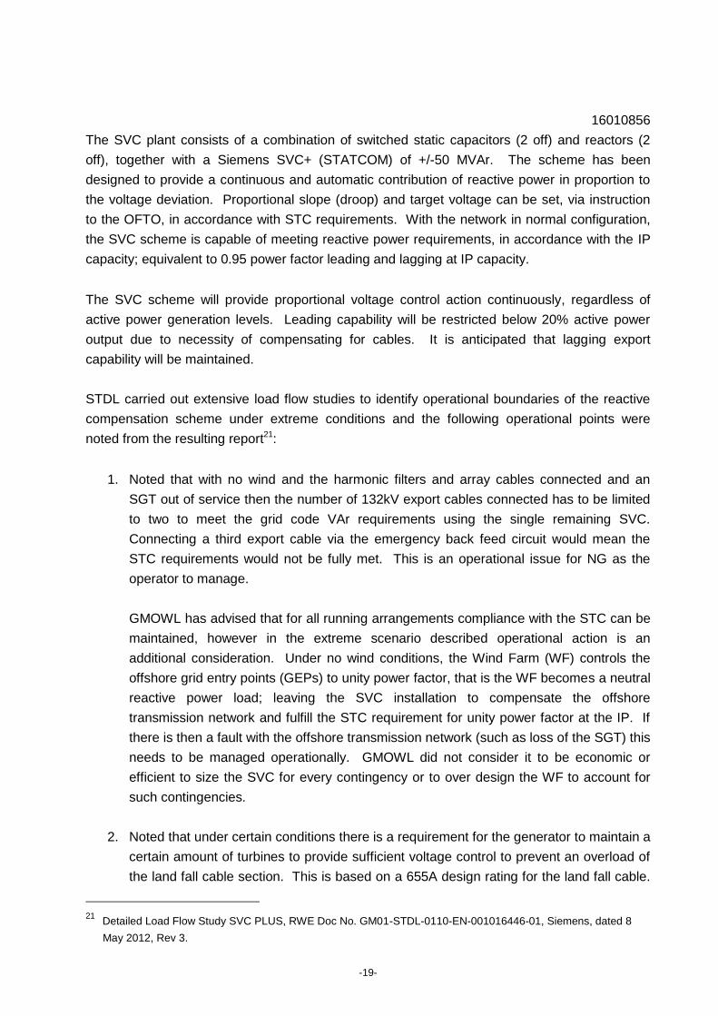
desired values, in accordance with the running arrangements. The overall HPPP control
structure is shown in the Figure 2 below.
Figure 2 High Performance Park Pilot (HPPP) Arrangement Schematic
It should be noted that ability to deliver the desired value of constant reactive power is
associated with WTG being in service and generating. Under conditions of ‘No Wind’, for
instance, this is not possible and control reverts to the delivery of unity power factor at the
respective slave HPPPs associated with a PPM.
400kV Interface Point Voltage Control Scheme
The IP control scheme has been designed such that equipment will contribute to the control of
voltage, at the Interface Point, as desired by the STC.
16010856
-19-
The SVC plant consists of a combination of switched static capacitors (2 off) and reactors (2
off), together with a Siemens SVC+ (STATCOM) of +/-50 MVAr. The scheme has been
designed to provide a continuous and automatic contribution of reactive power in proportion to
the voltage deviation. Proportional slope (droop) and target voltage can be set, via instruction
to the OFTO, in accordance with STC requirements. With the network in normal configuration,
the SVC scheme is capable of meeting reactive power requirements, in accordance with the IP
capacity; equivalent to 0.95 power factor leading and lagging at IP capacity.
The SVC scheme will provide proportional voltage control action continuously, regardless of
active power generation levels. Leading capability will be restricted below 20% active power
output due to necessity of compensating for cables. It is anticipated that lagging export
capability will be maintained.
STDL carried out extensive load flow studies to identify operational boundaries of the reactive
compensation scheme under extreme conditions and the following operational points were
noted from the resulting report21:
1. Noted that with no wind and the harmonic filters and array cables connected and an
SGT out of service then the number of 132kV export cables connected has to be limited
to two to meet the grid code VAr requirements using the single remaining SVC.
Connecting a third export cable via the emergency back feed circuit would mean the
STC requirements would not be fully met. This is an operational issue for NG as the
operator to manage.
GMOWL has advised that for all running arrangements compliance with the STC can be
maintained, however in the extreme scenario described operational action is an
additional consideration. Under no wind conditions, the Wind Farm (WF) controls the
offshore grid entry points (GEPs) to unity power factor, that is the WF becomes a neutral
reactive power load; leaving the SVC installation to compensate the offshore
transmission network and fulfill the STC requirement for unity power factor at the IP. If
there is then a fault with the offshore transmission network (such as loss of the SGT) this
needs to be managed operationally. GMOWL did not consider it to be economic or
efficient to size the SVC for every contingency or to over design the WF to account for
such contingencies.
2. Noted that under certain conditions there is a requirement for the generator to maintain a
certain amount of turbines to provide sufficient voltage control to prevent an overload of
the land fall cable section. This is based on a 655A design rating for the land fall cable.
21 Detailed Load Flow Study SVC PLUS, RWE Doc No. GM01-STDL-0110-EN-001016446-01, Siemens, dated 8
May 2012, Rev 3.
16010856
-20-
It is noted from the NKT land fall cable ampacity calculations that this section of the
marine cables has an estimated continuous rating of 611A and not 655A, however it
could cope with 655A for 11000hrs at a starting temperature based on a 75% loading
condition.
While this issue of cable ampacity is correct GMOWL wished to comment that the WTGs
operate in reactive power control not voltage control. They vary their terminal voltage as
the means of delivering or absorbing reactive power, but the High Performance Park
Pilot (HPPP) controller is operating in reactive power control mode. Automatic tap
change controls are applied to control the voltages at both the 33kV busbars offshore
and the 132kV busbar onshore. A certain number of turbines are required to be in
service to maintain the desired reactive power set-point. However it should be noted
that both the STC and the Grid Code allows for depleted reactive capability with reduced
plant in service. Thus if less than the necessary number of WTGs are in service the
reactive power at the 132kV level increases and the absorbing capability at the IP is
proportionately reduced. Under no wind conditions the offshore GEP is designed to
control to unity power factor (no wind control of the WTG) and the SVC installation is
sized to control the IP also to unity power factor (although it still operates in voltage
control and will thus still have lagging (export capability)).
3. There are other operational issues, power asymmetry above 90% between 33kV bus
sections that the wind farm operator needs to manage under certain extreme conditions.
Also, STDL recommended to ensure that the voltage of the two 33 kV busbars which are
related to the same onshore transformer do not differ by more than 1%.
4. For the calculation of the reactive power capability the SVC operating area was used. If
the complete range of the reactive power capability is used for low 400 kV voltages, the
current seen in the HV winding of the onshore transformer will be higher than the
thermal limit. GMOWL has advised that the SVC has an output limitation function which
will correct to keep the loading on the transformer within limits. This is particularly
relevant for conditions of low 400kV voltage.
5. The reactive power concept of the wind farm includes that the WTGs will provide
reactive power in order to optimise the rating of the SVC. The steady state voltage of
the WTGs at the LV side of the WTG transformer has to stay within +/-5%. Therefore
the range for the voltage of the 33 kV busbar is defined to be +/-1% in order to allow the
WTGs to operate well within their limits. Calculations have been carried out to point to
the consequences for the rating of the SVC if the 33 kV voltage is extended to +/-6%.
The currents in the compensation plant under this scenario would increase to nearly
10kA which will exceed the rating of the SVC and also the rating of the tertiary winding of
the onshore transformer (from the meeting with GMOWL on 3 Sept 2012 it was indicated

16010856
-21-
that the SVC limits itself to 95MVAr to avoid this). GMOWL has also advised that +/- 5%
of the WTG terminal voltage is recommended by Siemens Wind Power as the design
range; hence this was used in the load flow study. In operation the WTG terminal
voltage can vary by +/- 8%. WTG terminal voltage is a controlled variable, based upon
reactive power delivery at the 132kV point. The 33kV voltage is required to be controlled
(by the 132/33kV transformer automatic tap changer control (ATCC)) to 1pu (+/- 1%)
and within 1% asymmetry in order to efficiently deliver turbine reactive capability.
SCADA
Offshore transmission assets are planned to be operated from a stand-alone SCADA system
that is independent of the Generator SCADA system. Each of the two offshore substations and
the onshore substation are designed to have separate OFTO and Generator SCADA equipment
rooms. The proposed Generator and OFTO SCADA systems are responsible for the
supervision of all switchgear within the onshore and offshore substations, associated control
and protection and various common facilities (e.g. fire and safety systems, diesel generators,
battery back up systems etc).
Redundancy in electrical design
The offshore transmission system is designed according to the planning criteria defined in the
NETS SQSS22. The standard requires that for the loss of a single AC transformer circuit on an
offshore substation platform, the loss of power infeed shall not exceed 50% of the grid entry
point capacity. This has led to the project design requirement for 2 x 50% rated transformers on
each offshore substation, each connected to a 132kV export cable circuit to shore.
Each transformer picks up 50% of the output from each platform where each transformer has a
design rating of 25% of the total output from the wind farm. The same can be said for the four
subsea cables. For the loss of one of the 400kV onshore circuits or one of the two offshore
substation platforms in its entirety, a minimum of 50% of the total output from the wind farm
would need to be maintained in order to meet the requirements of NETS SQSS23. The project
has been designed such that this condition is appropriately met (noting some operational
requirements under extreme conditions when one SGT is out of service along with the
associated SVC, discussed earlier).
The onshore 132kV busbar is, as per the requirements of the NETS SQSS, of double busbar
type and therefore enables full export to be maintained on occurrence of a 132kV onshore
busbar fault, i.e. following post fault re-configuration of the 132kV busbar connections. The
22
National Electricity Transmission System Security and Quality of Supply Standard 23
National Electricity Transmission System Security and Quality of Supply Standard
16010856
-22-
132kV busbar arrangements also allow up to all four offshore export circuits to be connected to
a single SGT should the need arise.
As four independent 132kV cables connect approximately 25% of the installed capacity each,
the ratings selected result in the need for a power constraint of up to a maximum of 25% should
there be a failure of one offshore transformer or 132kV cable. At the offshore substation the two
33kV busbar sections, one per offshore transformer can be linked together should one
transformer or export cable be unavailable. This arrangement allows the generation from the
wind farm to be maximised up to the limit of the remaining 132kV export circuit and up to
approximately 75% of the 576MW Transmission Entry Capacity (TEC). The 132kV substation
arrangements combined with the 33kV link arrangements between 33kV busbar sections at
each offshore substation avoids the need for 132kV busbars and switchgear at the offshore
substations.
Performance and Availability
The developer has calculated availability of the OFTO assets to be between 98.4% to 99.7%
depending on if the weather is good or bad and whether spare parts are available or not.24
However, it is noted that these figures are for unplanned failures and do not account for planned
unavailability due to plant isolations for planned maintenance.
To reduce unavailability due to unplanned events, GMOWL has procured spares for the
transmission system, including spare onshore and offshore transformers and spare 132kV
onshore and offshore export cable25. While the spare onshore transformer will be transferred to
the OFTO, GMOWL plan to keep the offshore transformer. Also, it is indicated that there will be
spare 132kV onshore and marine cable, however, no cable has been identified for transfer to
the OFTO.
The spare 400/132kV transformer is located at the onshore substation to facilitate rapid
replacement if required.
2.1.4 Spare Onshore Transformer Justification
A business case for the spare 400/132kV transformer based on the calculated risk and cost of
lost energy from the wind farm has been made by GMOWL and shows a positive benefit to
24 Siemens report, " System Unavailability Analysis" document reference GM01-STDL-0110-EN-001016464-01,
30/3/2012, rev 02. 25
Information Memorandum Gwynt y Mor Offshore Transmission Assets, January 2011.

16010856
-23-
purchasing the spare transformer26. It is noted that if the business case was made by an OFTO
based on penalties for lost availability this may not show a business case for transformer
purchase. GMOWL has indicated (verbally at meeting on 3 Sept 2012) that considering lost
energy sales to the wind farm in assessing the business case was agreed by Ofgem.
It is noted that GMOWL deem the procurement of a spare transformer is not building above the
NET SQSS requirements. GMOWL believe that all credible failure rates (FR) and mean times
to repair (MTTR) support the purchase of a spare transformer, i.e. all combinations of FR=>1%
and MTTRs=>3285hrs result in incremental lost energy valued of xxxxxxxxx (the cost of the
spare transformer). GMOWL has also indicated that the onshore transformers are a non
standard design and it is unlikely a spare would be available, hence a new transformer would
require to be ordered taking 12 months (plus) to arrive at site.
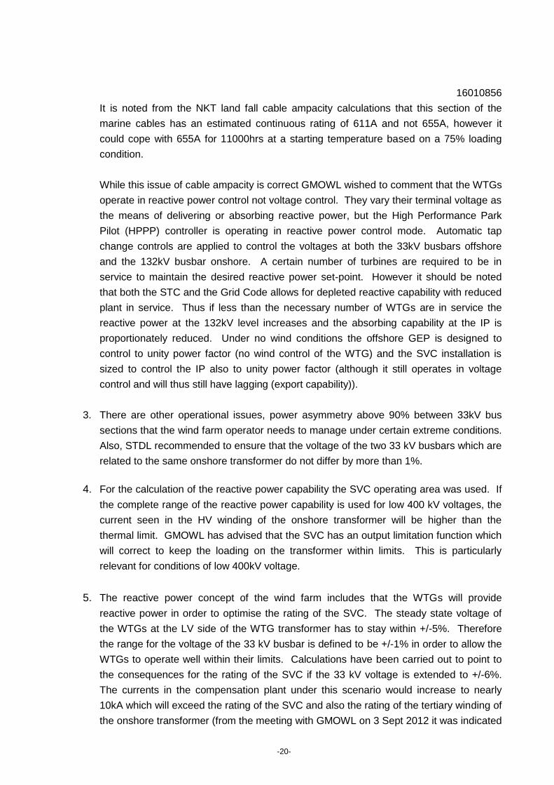
2.2 Offshore Transmission Assets Overview
The simplified single line diagram for the GMOWL project is shown in Figure 3.
26
GyM Spare Transformer CBA Note - 26th July 2012.pdf. (provided by Fiona Alexander of Ofgem in email dated 17
Aug 2012)

16010856
-24-
Figure 3: GMOWL simplified single line diagram (source: Information Memorandum)
A list of the main onshore and offshore transmission assets, proposed ownership and life
expectancy is provided in Appendix C1. All electrical equipment has been specified to
standards issued by the International Electrotechnical Commission (IEC) and International
Organisation for Standardisation (ISO) as fit for the purpose intended and project compliant in
that the equipment will meet the specified contractual 25 year27 design life of the OFTO system.
2.2.1 Offshore Substations
Each OSP contains two 132/33kV 160MVA transformers each connected to a 33kV bus-bar
with a link between the busbar sections which is run normally open. The 33kV feeders
connecting the wind turbines are split equally between the two bus sections. The
27
Information Memorandum Gwynt y Mor Offshore Transmission Assets, January 2011.
16010856
-25-
OFTO/GMOWL boundary is located at the lower voltage terminals of the 132/33kV
transformers.
The 160 Siemens 3.6MW turbines will be divided equally between OSP East and OSP West
respectively. Each OSP has 8 outgoing wind turbine collection feeders, four per 33kV bus-bar
section.
2.2.2 Onshore Substation
The OFTO onshore 132kV substation is adjacent to the new NGET 400kV Bodelwyddan
substation which includes two 400kV GIS bays to connect the Gwynt y Mor wind farm.
The OFTO onshore substation includes two 400/132kV auto-transformers which are rated at
320MVA. A tertiary winding (13.9kV, 130MVA) is used on each transformer to connect
approximately +110/-120MVAr of reactive compensation to meet both steady-state and dynamic
Grid Code requirements. This level of compensation is made up from a SVC unit (of a multi-
level VSC design marketed as SVC+ by STDL) and two additional mechanically switched
reactors (MSR) rated at 55MVAr and two mechanically switched capacitors (MSC) rated at
30MVAr. The control strategy is such that the SVC can continuously operate over a ±50MVAr
range and when required the MSR/MSC can be switched in to provide the full range (note that
the reactive capability of the wind turbines is also utilised through the HPPP wind farm control
system). The proposed ratings and control strategy of the SVC and MSR/MSC has been
finalised by STDL to ensure that the Grid Code requirements can be met. Harmonic filters have
also been installed (40MVAr Siemens C-Type) in order to ensure compliance with ER G5/4-1
requirements28.
2.2.3 Export Cables
The 132kV export circuits are made up of onshore and offshore sections. For the former, each
land feeder uses three 1000mm2, aluminium, XPLE, single-core cables each with an
approximate length of 11.1km. The submarine circuit uses 500mm2, copper, XLPE, three-core
cables, the cables to the East OSP being 22.4km in length and those to the West OSP being
19km. It is noted that the GMOWL marine cables will traverse the Rhyl Flats wind farm export
cable and also a gas pipe.
28
Engineering Recommendation ER G5/4-1, ``Planning levels for harmonic voltage distortion and the connection of
nonlinear equipment to transmission systems and distribution networks in the United Kingdom'.
16010856
-26-
2.3 Compliance with industry codes and standards
The GMOWL project is designed as an integrated system, compliant with the current Grid Code
requirements at the onshore connection point. DNV KEMA's assessment of the project
compliance with the industry codes is provided in Appendix C2-C4. Where information has
been provided, the project was found to be compliant.
All equipment has been designed with reference to international (EN, IEC, ISO), National Grid
(NGTS) and national standards. Where EN, IEC or ISO standards have been adopted by
British Standards then the BS EN version takes precedence.
2.4 Conclusions
A high level technical review of GMOWL transmission assets conducted by DNV KEMA has
concluded that GMOWL has adopted and implemented a standard engineering design process
which has been reasonably well documented and can be considered representative of a
widespread and good practice design internationally. The engineering design philosophy
adopted and the electrical design work initially carried out by the developer and finalised by the
preferred contractor (STDL) resulted in a well thought through and fit for purpose design of the
offshore transmission infrastructure.
Based on various relevant design and planning information provided to and reviewed by DNV
KEMA, the following specific observations can be made in relation to the adopted design
process, design philosophy, onshore substation design and overall project compliance:
The project overall design engineering process followed a standard well established and
recognised design approach starting with the conceptual design (e.g. consideration of
feasibility options and topologies) and following through with the full technical and
functional specifications and required system studies. Evidence of review meetings at
key stages in the project development was not found.
The offshore transmission network layout, export cable transmission voltage and ratings
and overall electrical infrastructure design and equipment ratings underwent detailed
analysis in terms of their viability and technical and economic optimisation. As a result,
the design of the proposed offshore transmission infrastructure appears well justified and
fit for purpose.
All relevant offshore equipment has been specified to international or national standards.
Where relevant information has been made available the offshore transmission system
is compliant with the planning criteria and connection requirements specified in industry
framework documents including the National Electricity Transmission System Security

16010856
-27-
and Quality of Supply Standard (NETS SQSS), System Operator and Transmission
Owner Code (STC) and Grid Code.

16010856
-28-
3 PROCUREMENT
GMOWL has adopted a multi package contracting strategy for the Gwynt y Mor offshore wind
farm. In relation to the OFTO transmission connection the following main packages have been
tendered and awarded:
Electrical Systems Package (ESP), awarded to STDL
Onshore cable supply and installation, awarded to Prysmian
Offshore cable supply, awarded to NKT
Offshore cable installation, awarded to Global Marine.
OSP Jackets design and fabrication, awarded to Burnt Island Fabrication (BIFAB)
OSP Jacket installation, awarded to Seaway Heavy Lift (SHL)
OSP topside transport and lift, awarded to SHL
Two 400kV bays unlicensed works contract was placed with NGET.
3.1 Tender for the Electrical Systems Package
3.2 Onshore Cable Supply and Installation Package
3.3 Offshore Cable Supply Package
3.4 Offshore Cable Installation Package
3.5 OSP Jacket Design and Fabrication Package
16010856
-29-
3.6 OSP Jacket Installation
3.7 OSP Topside Transport and Lift Package
3.8 Two 400kV bays unlicensed works contract was placed with NGET.
3.9 Installation Progress at beginning of September 2012
Progress on the installation contracts was provided by GMOWL and is summarised in the
following.
Offshore Substation Platform Foundations Design and Fabrication Package
The BIFAB design and supply contract is complete and has now been closed out, with final
account discussions nearing completion.
Electrical System Package
Onshore Substation
STDL continue to progress the onshore works in line with their latest programme, which has
all works completed by 14 December 2012. Work is nearing completion on the 132kV GIS
switch room building, cold commissioning of the equipment and internal wiring of the
building.
Offshore Substations
The East OSP was successfully installed over the night of the 14 August 2012. The West
OSP was installed on 26 Aug 2012.
Onshore 132kV Export Cables Supply and Install Package.
All onshore cables have been installed by Prysmian. HV testing is planned to start 7 Sept
2012 on the onshore export cables. Reinstatement along the cable route is ongoing and all
landowners have agreed how their land will be reinstated.
Offshore 132kV Export Cable Supply Package and Installation Package.
16010856
-30-
To date, approx. 9 km of the first export offshore cable has been laid by Global Marine.
Cables 1 and 2 supplied by NKT are on the Global Marine Cable Enterprise vessel and the
installation vessel has transited to the wind farm site. Cables 3 and 4 supplied by NKT are
now loaded onto the Global Marine UR141 barge, which has transited to Liverpool. NKT are
to provide additional support for jointing and ongoing maintenance.
Grid Connection
The National Grid 400kV Bodelwyddan Sub Station has now been adopted into NGET’s
Safety Rules. RWE NRL Safety Rules were implemented at St Asaph substation from 1200
hrs on the 10 August 2010. The 400kV circuits 1 and 2 up to the power quality monitoring
VTs have been included within the Safety Rules Clearance Certificate (SRCC). First
energisation of the circuits took place on 12 August 2012. NGET has been undertaking
power quality monitoring (PQM).
Onshore Commissioning
The St Asaph substation Control Person Operations (CPO) role will be fulfilled by NGET up
to sub station handover in December 2012, due to substation SCADA control system issues.
NGET has agreed to this strategy, as it is a NGET project issue. The substation
commissioning works are progressing to programme.
Offshore Commissioning
Offshore commissioning through diesel generators will commence shortly after the OSP
topsides are installed.

16010856
-31-
APPENDIX A – TECHNICAL ASSESSMENT

16010856
-32-
Appendix A1. Electrical equipment and system design

16010856
-33-
Equipment Owner Type & ratings Rating Voltage Life
Expectancy
(contracted
or
estimated)
Applicable
Standards -
see contracts
for details
Quantity for
both platforms
Design Comment
Shunt capacitors OFTO 30MVAr 13.9kV 25 years BSEN60871 4 reacitve compensation
Shunt reactors OFTO 55MVAr 13.9kV 25 years BSEN 4 reacitve compensation
SVC OFTO +/- 50MVAr 13.9kV 25 years BSEN 2 reacitve compensation
Harmonic Filters OFTO Siemns C Type 40MVAr 132kV 25 years BSEN 2
Protection and control equipment (CVTs,
surge arresters, post CTs)
OFTO not known not known 25 years BSEN
Miscellaneous (LV cable, lightning
protection and earthing, ).
OFTO not known not known 25 years BSEN Protection relays are likely to need replacement or
upgrades after 15 to 20 years.
Auxilliary supply transformers OFTO 500kVA 13.9/0.4kV 25 years BSEN60076 2
ac and dc supplies OFTO not known 400/230V
ac.
25 years BSEN 2 Batteries Life 10years
Manweb backup supply transformer. OFTO up to 250kVA 11/0.4kV 25 years BSEN 1
Back-up supply cable(s) from SP
MANWEB LV board
OFTO not known 400/230V
ac.
25 years BSEN 1
Ancillary DC & UPS supplies including
batteries and distribution switchgear
OFTO not known not known 25 years BSEN Batteries Life 10years
Central monitoring control scheme
(CMCS)
OFTO not known not known 25 years BSEN 2
Communication network OFTO fibre optic 48 core at
132kV; 24
132kV and
33kV
25 years BSEN
Onshore NGET 400kV Substation
OFTO Elements400kV breaker bays OFTO ABB ELK-3 4000A 420kV 40 years NGTS 2
400kV cables from CBs to TFRs OFTO not known not known 400kV 40 years BSEN Size being selected to address 29th Harmonic voltage
distortion issue.
400kV cable sealing ends OFTO not known not known 400kV 40 years NGTS
400kV CTs and VTs for harmonic
monitoring to 100th harmonic
OFTO not known not known 400kV 40 years NGTS

16010856
-34-
Appendix A2. National Electricity Transmission System Security and Quality of Supply Standard Compliance Assessment

16010856
-35-
Requirement Info Provided Assessment
Comment & Result
Compliance Action
1.14 to
1.25
Offshore Criteria & Methodologies Ownership and boundaries of
offshore transmission system
components.
The OFTO ownership 400kV circuit boundaries
are proposed to be the gas barrier between the
isolator gas zone and the circuit buffer gas zone,
GMOWL presently own the zone between the
busbar gas zones and circuit breaker gas zone.
The 33kV ownership boundary will be at the
busbar clamps of 33kV circuit breakers (Generator
owned) on the LV side of offshore grid
transformers (TX5, TX6, TX7, TX8). Data from
RWE document STC Part 12,Services Capability
Specification Guidance Notes Reference: Part 3 –
4.3. Substation Operational Guide 1
SUBSTATION OPERATIONAL GUIDE Substation:
Gwynt y Mor (132kV) prepared by RWE. Draft for
comment.
Compliant None
7.2.1 Maximum capacity of offshore
PPM
Maximum of 1500MW CEC 590MW, TEC 574MW. (BCA dated 9 August
2010)
Compliant None
7.2.3 Distance GEP to IP Maximum 100km Longest offshore cable 22.4km
All onshore cables 11.1km.
Longest circuit Total 2 x 33.5kM.
Information Memorandum.
Compliant None
7.2.4 Length of any overhead line
section
Maximum 50km not applicable Compliant None
7.2.5 Offshore network configuration Radial only The transmission connections and LV cable
arrays will be operated as radial circuits.
Compliant None
7.8.1.1 Planned or fault outage of a single
AC offshore transformer circuit
Where GEP capacity is 90MW+,
planned or fault outage of a single
AC offshore transformer circuit the
loss of power infeed shall not
exceed the smallest of either 50%
of the offshore GEP or the full
normal infeed loss risk (at present
1000MW for frequency deviations of
greater than 0.5Hz for longer term)
Failure of a 132kV circuit will result in a 25%
capacity reduction. Failure of a 400kV circuit or
400/132kV SGT will result in a 50% capacity
reduction. With a main and reserve 132kV
busbar, in the event of a busbar fault, the 132kV
substation can be reconfigured to provide 100%
capacity. Network single line diagram and
Information Memorandum.
Compliant None
7.8.1.3 Fault outage of single AC offshore
transmission circuit during a
The loss of power infeed shall not
exceed the infrequent infeed loss
This scenario would result in a maximum 50%
capacity reduction as there are four independent
Compliant None
7.8.2.1 Planned or fault outage of a single
DC converter
Loss of power infeed shall not
exceed the normal infeed loss risk
not applicable n/a None
NETS SQSS Reference
16010856
-36-
Requirement Info Provided Assessment
Comment & Result
Compliance Action
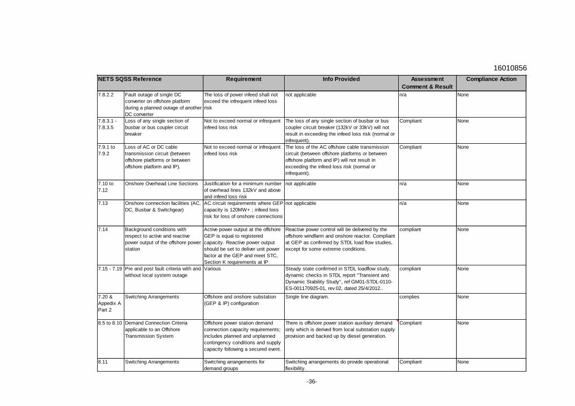
7.8.2.2 Fault outage of single DC
converter on offshore platform
during a planned outage of another
DC converter
The loss of power infeed shall not
exceed the infrequent infeed loss
risk
not applicable n/a None
7.8.3.1 -
7.8.3.5
Loss of any single section of
busbar or bus coupler circuit
breaker
Not to exceed normal or infrequent
infeed loss risk
The loss of any single section of busbar or bus
coupler circuit breaker (132kV or 33kV) will not
result in exceeding the infeed loss risk (normal or
infrequent).
Compliant None
7.9.1 to
7.9.2
Loss of AC or DC cable
transmission circuit (between
offshore platforms or between
offshore platform and IP).
Not to exceed normal or infrequent
infeed loss risk
The loss of the AC offshore cable transmission
circuit (between offshore platforms or between
offshore platform and IP) will not result in
exceeding the infeed loss risk (normal or
infrequent).
Compliant None
7.10 to
7.12
Onshore Overhead Line Sections Justification for a minimum number
of overhead lines 132kV and above
and infeed loss risk
not applicable n/a None
7.13 Onshore connection facilities (AC,
DC, Busbar & Switchgear)
AC circuit requirements where GEP
capacity is 120MW+ ; infeed loss
risk for loss of onshore connections
not applicable n/a None
7.14 Background conditions with
respect to active and reactive
power output of the offshore power
station
Active power output at the offshore
GEP is equal to registered
capacity. Reactive power output
should be set to deliver unit power
factor at the GEP and meet STC,
Section K requirements at IP
Reactive power control will be delivered by the
offshore windfarm and onshore reactor. Compliant
at GEP as confirmed by STDL load flow studies,
except for some extreme conditions.
compliant None
7.15 - 7.19 Pre and post fault criteria with and
without local system outage
Various Steady state confirmed in STDL loadflow study,
dynamic checks in STDL report "Transient and
Dynamic Stability Study", ref GM01-STDL-0110-
ES-001170925-01, rev 02, dated 25/4/2012..
compliant None
7.20 &
Appedix A
Part 2
Switching Arrangements Offshore and onshore substation
(GEP & IP) configuration
Single line diagram. complies None
8.5 to 8.10 Demand Connection Criteria
applicable to an Offshore
Transmission System
Offshore power station demand
connection capacity requirements;
includes planned and unplanned
contingency conditions and supply
capacity following a secured event.
There is offshore power station auxiliary demand
only which is derived from local substation supply
provision and backed up by diesel generation.
Compliant None
8.11 Switching Arrangements Switching arrangements for
demand groups
Switching arrangements do provide operational
flexibility.
Compliant None
NETS SQSS Reference
16010856
-37-
Requirement Info Provided Assessment
Comment & Result
Compliance Action
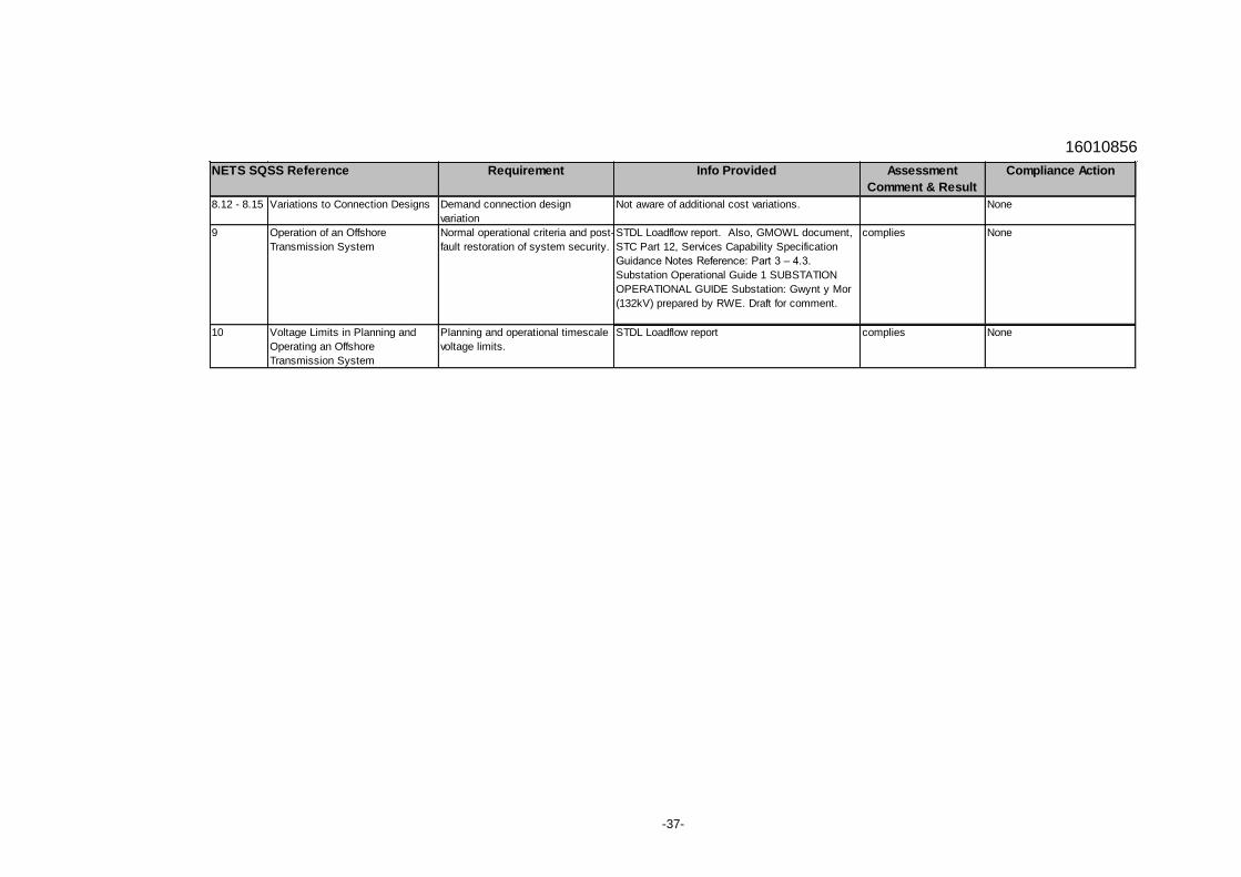
8.12 - 8.15 Variations to Connection Designs Demand connection design
variation
Not aware of additional cost variations. None
9 Operation of an Offshore
Transmission System
Normal operational criteria and post-
fault restoration of system security.
STDL Loadflow report. Also, GMOWL document,
STC Part 12, Services Capability Specification
Guidance Notes Reference: Part 3 – 4.3.
Substation Operational Guide 1 SUBSTATION
OPERATIONAL GUIDE Substation: Gwynt y Mor
(132kV) prepared by RWE. Draft for comment.
complies None
10 Voltage Limits in Planning and
Operating an Offshore
Transmission System
Planning and operational timescale
voltage limits.
STDL Loadflow report complies None
NETS SQSS Reference
16010856
-38-
Appendix A3. System Operator – Transmission Owner Code Compliance Assessment
16010856
-39-
Requirement Info Provided Assessment
Comment & Result
Compliance Action
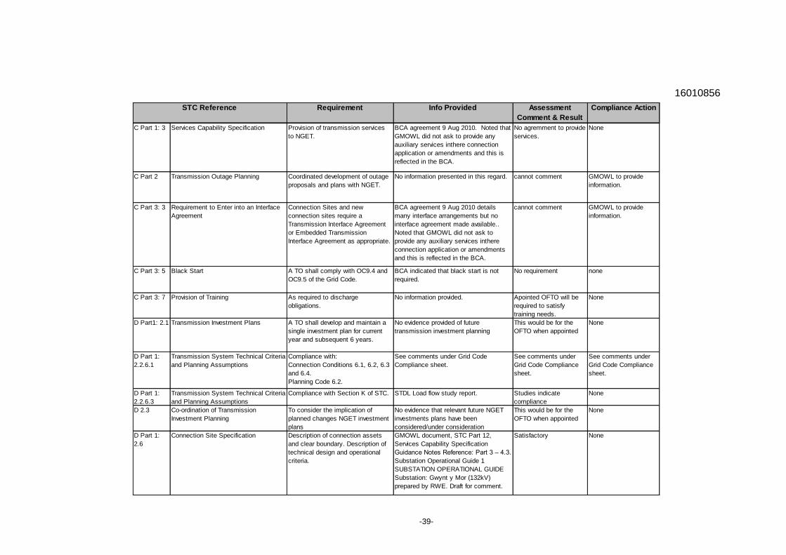
C Part 1: 3 Services Capability Specification Provision of transmission services
to NGET.
BCA agreement 9 Aug 2010. Noted that
GMOWL did not ask to provide any
auxiliary services inthere connection
application or amendments and this is
reflected in the BCA.
No agremment to provide
services.
None
C Part 2 Transmission Outage Planning Coordinated development of outage
proposals and plans with NGET.
No information presented in this regard. cannot comment GMOWL to provide
information.
C Part 3: 3 Requirement to Enter into an Interface
Agreement
Connection Sites and new
connection sites require a
Transmission Interface Agreement
or Embedded Transmission
Interface Agreement as appropriate.
BCA agreement 9 Aug 2010 details
many interface arrangements but no
interface agreement made available..
Noted that GMOWL did not ask to
provide any auxiliary services inthere
connection application or amendments
and this is reflected in the BCA.
cannot comment GMOWL to provide
information.
C Part 3: 5 Black Start A TO shall comply with OC9.4 and
OC9.5 of the Grid Code.
BCA indicated that black start is not
required.
No requirement none
C Part 3: 7 Provision of Training As required to discharge
obligations.
No information provided. Apointed OFTO will be
required to satisfy
training needs.
None
D Part1: 2.1 Transmission Investment Plans A TO shall develop and maintain a
single investment plan for current
year and subsequent 6 years.
No evidence provided of future
transmission investment planning
This would be for the
OFTO when appointed
None
D Part 1:
2.2.6.1
Transmission System Technical Criteria
and Planning Assumptions
Compliance with:
Connection Conditions 6.1, 6.2, 6.3
and 6.4.
Planning Code 6.2.
See comments under Grid Code
Compliance sheet.
See comments under
Grid Code Compliance
sheet.
See comments under
Grid Code Compliance
sheet.
D Part 1:
2.2.6.3
Transmission System Technical Criteria
and Planning Assumptions
Compliance with Section K of STC. STDL Load flow study report. Studies indicate
compliance
None
D 2.3 Co-ordination of Transmission
Investment Planning
To consider the implication of
planned changes NGET investment
plans
No evidence that relevant future NGET
investments plans have been
considered/under consideration
This would be for the
OFTO when appointed
None
D Part 1:
2.6
Connection Site Specification Description of connection assets
and clear boundary. Description of
technical design and operational
criteria.
GMOWL document, STC Part 12,
Services Capability Specification
Guidance Notes Reference: Part 3 – 4.3.
Substation Operational Guide 1
SUBSTATION OPERATIONAL GUIDE
Substation: Gwynt y Mor (132kV)
prepared by RWE. Draft for comment.
Satisfactory None
STC Reference

16010856
-40-
Requirement Info Provided Assessment
Comment & Result
Compliance Action
D Part 1:
2.7
Transmission Interface Site
Specification
as above as above Satisfactory None
D Part 1:
2.8
Embedded Transmission Site
Specification
as above as above Satisfactory None
D Part 1:
3
Default Planning Boundary Guidance on planning boundaries.
Check appropriateness of developer
proposed boundaries.
as above Satisfactory None
D Part 2:
2
NGET Construction Application Requirement is to have a TO
Construction Agreement
Latest constuction agreement provided
is dated 10 Jan 2010.
compliant None
D Part 2:
3
Construction Planning Assumptions Issued to TO to assist in
preparation of Construction Offer.
Appendix P in construction agreement,
however, these assumptions are out of
date. NGET assumed to have relevent
assumptions but no documented
partially compliant GMOWL to confirm up
to date assumptions
were passed to NGET.
D Part 2:
4
TO Construction Offer Each TO that receives a NGET
Construction Application must notify
NGET if it intends to submit a TO
Construction Offer.
n/a n/a n/a
D Part 2:
5
Acceptance of TO Construction Offer Offer will remain open for at least 6
months.
n/a n/a n/a
D Part 2:
10
Communications Plant NGET and TO to agree provision of
communications equipment.
Information on control, protection and
telephony communications provided.
BCA, construction agreement, GMOWL
electrical system package scope.
Complete. None
D Part 2:
11 to 13
Site Rules Provision of Safety Rules for all site
types to be submitted prior to
Completion Date of Construction
Agreement.
NGET Operational Notification
Compliance Checklist.
Complete. None.
G 2.2 Transmission Owner Safety
Requirements
TO shall comply with the relevant
appendix of Operating Code 8 and
Appendix 1 of the Connection
Conditions of the Grid Code.
NGET Operational Notification
Compliance Checklist. Indicates RWE
safety rules have been sent to NGET
and that NGET and RWE has agreed
local safety procedures during
commissioning and after commissioning
is complete.
substantly complete. None.
STC Reference
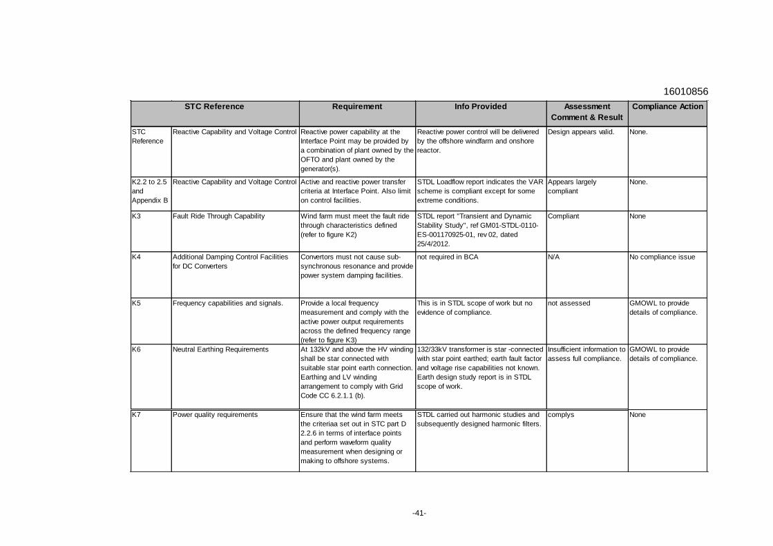
16010856
-41-
Requirement Info Provided Assessment
Comment & Result
Compliance Action
STC
Reference
Reactive Capability and Voltage Control Reactive power capability at the
Interface Point may be provided by
a combination of plant owned by the
OFTO and plant owned by the
generator(s).
Reactive power control will be delivered
by the offshore windfarm and onshore
reactor.
Design appears valid. None.
K2.2 to 2.5
and
Appendix B
Reactive Capability and Voltage Control Active and reactive power transfer
criteria at Interface Point. Also limit
on control facilities.
STDL Loadflow report indicates the VAR
scheme is compliant except for some
extreme conditions.
Appears largely
compliant
None.
K3 Fault Ride Through Capability Wind farm must meet the fault ride
through characteristics defined
(refer to figure K2)
STDL report "Transient and Dynamic
Stability Study", ref GM01-STDL-0110-
ES-001170925-01, rev 02, dated
25/4/2012.
Compliant None
K4 Additional Damping Control Facilities
for DC Converters
Convertors must not cause sub-
synchronous resonance and provide
power system damping facilities.
not required in BCA N/A No compliance issue
K5 Frequency capabilities and signals. Provide a local frequency
measurement and comply with the
active power output requirements
across the defined frequency range
(refer to figure K3)
This is in STDL scope of work but no
evidence of compliance.
not assessed GMOWL to provide
details of compliance.
K6 Neutral Earthing Requirements At 132kV and above the HV winding
shall be star connected with
suitable star point earth connection.
Earthing and LV winding
arrangement to comply with Grid
Code CC 6.2.1.1 (b).
132/33kV transformer is star -connected
with star point earthed; earth fault factor
and voltage rise capabilities not known.
Earth design study report is in STDL
scope of work.
Insufficient information to
assess full compliance.
GMOWL to provide
details of compliance.
K7 Power quality requirements Ensure that the wind farm meets
the criteriaa set out in STC part D
2.2.6 in terms of interface points
and perform waveform quality
measurement when designing or
making to offshore systems.
STDL carried out harmonic studies and
subsequently designed harmonic filters.
complys None
STC Reference

16010856
-42-
Appendix A4. Grid Code Compliance Assessment
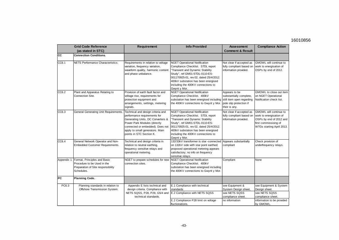
16010856
-43-
Requirement Info Provided Assessment
Comment & Result
Compliance Action
CC Connection Conditions.
CC6.1 NETS Performance Characteristics. Requirements in relation to voltage
variation, frequency variation,
waveform quality, harmonic content
and phase unbalance.
NGET Operational Notification
Compliance Checklist. STDL report
"Transient and Dynamic Stability
Study", ref GM01-STDL-0110-ES-
001170925-01, rev 02, dated 25/4/2012.
400kV substation has been energised
including the 400KV connections to
Gwynt y Mor.
Not clear if accepted as
fully compliant based on
information provided.
GMOWL will continue to
work to energisation of
OSPs by end of 2012.
CC6.2 Plant and Apparatus Relating to
Connection Site.
Provision of earth fault factor and
voltage rise, requirements for
protection equipment and
arrangements, settings, metering
signals.
NGET Operational Notification
Compliance Checklist. 400kV
substation has been energised including
the 400KV connections to Gwynt y Mor.
Appears to be
substantially complete,
still item open regarding
pole slip protection if
their is any.
GMOWL to close out item
on NGET Operational
Notification check list.
CC6.3 General Generating Unit Requirements. Technical and design criteria and
performance requirements for
Generating Units, DC Converters &
Power Park Modules (directly
connected or embedded). Does not
apply to small generators. Main
points in STC Section K.
NGET Operational Notification
Compliance Checklist. STDL report
"Transient and Dynamic Stability
Study", ref GM01-STDL-0110-ES-
001170925-01, rev 02, dated 25/4/2012.
400kV substation has been energised
including the 400KV connections to
Gwynt y Mor.
Not clear if accepted as
fully compliant based on
information provided.
GMOWL will continue to
work to energisation of
OSPs by end of 2012 and
first commissioing of
WTGs starting April 2013.
CC6.4 General Network Operator and Non-
Embedded Customer Requirements.
Technical and design criteria in
relation to neutral earthing,
frequency sensitive relays and
operational metering.
132/33kV transformer is star -connected
on 132kV side with star point earthed;
proposed operational metering appears
satisfactory; no info on frequency
sensitive relays.
Appears substantially
compliant
Check provision of
underfrequency relays.
Appendix 1 Format, Principles and Basic
Procedure to be Used in the
Preparation of Site responsibility
Schedules.
NGET to prepare schedules for new
connection sites.
NGET Operational Notification
Compliance Checklist. 400kV
substation has been energised including
the 400KV connections to Gwynt y Mor.
Compliant None
PC Planning Code.
E.1 Compliance with technical
standards
see Equipment &
System Design sheet,
see Equipment & System
Design sheet.
E.2 Compliance with NETS SQSS see NETS SQSS
compliance sheet.
see NETS SQSS
compliance sheet.
E.2 Compliance P28 limit on voltage
fluctionations.
no information information to be provided
by GMOWL.
Grid Code Reference
(as stated in STC)
PC6.3 Planning standards in relation to
Offshore Transmission System.
Appendix E lists technical and
design criteria. Compliance with
NETS SQSS, P28, P29, G5/4 and
technical standards.
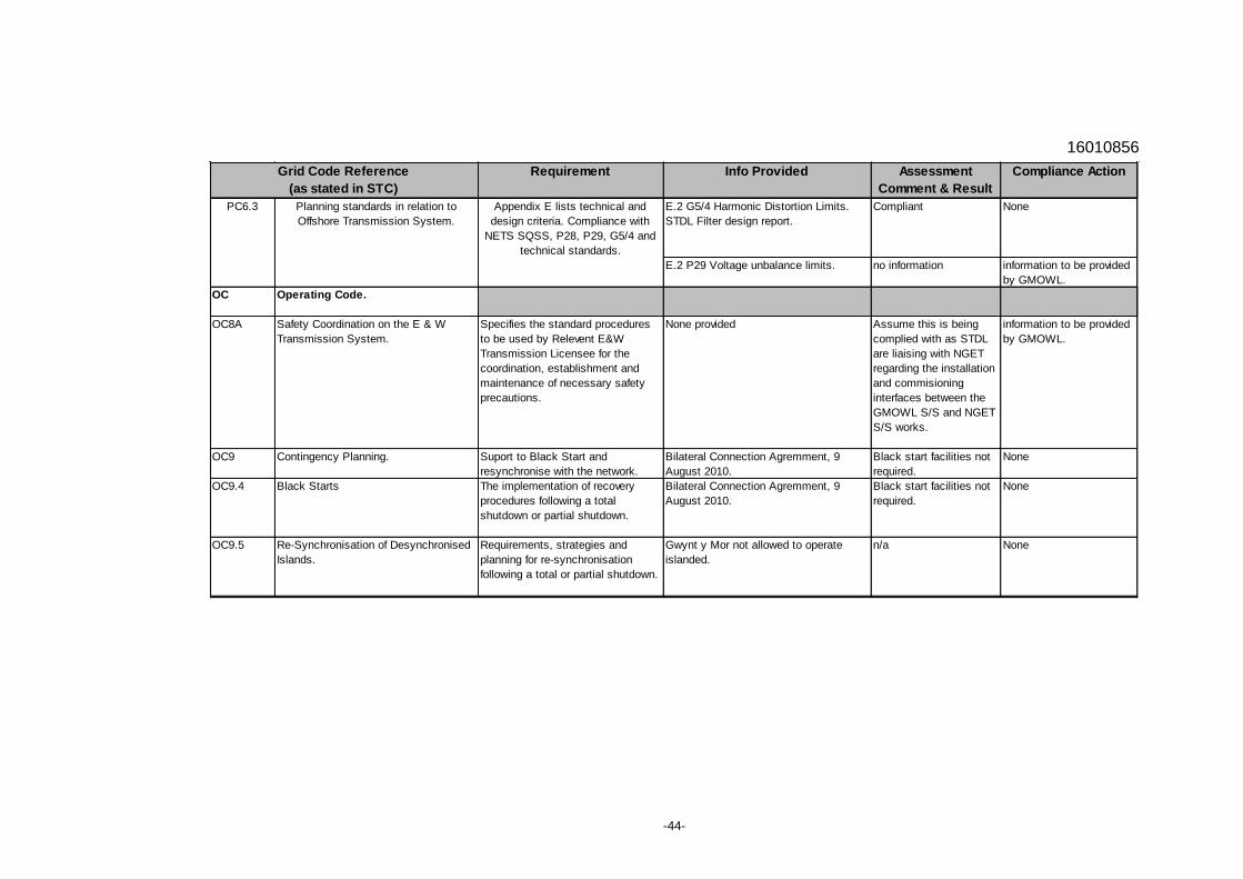
16010856
-44-
Requirement Info Provided Assessment
Comment & Result
Compliance Action
E.2 G5/4 Harmonic Distortion Limits.
STDL Filter design report.
Compliant None
E.2 P29 Voltage unbalance limits. no information information to be provided
by GMOWL.
OC Operating Code.
OC8A Safety Coordination on the E & W
Transmission System.
Specifies the standard procedures
to be used by Relevent E&W
Transmission Licensee for the
coordination, establishment and
maintenance of necessary safety
precautions.
None provided Assume this is being
complied with as STDL
are liaising with NGET
regarding the installation
and commisioning
interfaces between the
GMOWL S/S and NGET
S/S works.
information to be provided
by GMOWL.
OC9 Contingency Planning. Suport to Black Start and
resynchronise with the network.
Bilateral Connection Agremment, 9
August 2010.
Black start facilities not
required.
None
OC9.4 Black Starts The implementation of recovery
procedures following a total
shutdown or partial shutdown.
Bilateral Connection Agremment, 9
August 2010.
Black start facilities not
required.
None
OC9.5 Re-Synchronisation of Desynchronised
Islands.
Requirements, strategies and
planning for re-synchronisation
following a total or partial shutdown.
Gwynt y Mor not allowed to operate
islanded.
n/a None
Planning standards in relation to
Offshore Transmission System.
Grid Code Reference
(as stated in STC)
PC6.3 Appendix E lists technical and
design criteria. Compliance with
NETS SQSS, P28, P29, G5/4 and
technical standards.