Embed Size (px)
Citation preview

Yale University Design Standards
15950 Energy Management and Control Systems
This document provides design standards only, and is not intended for use, in whole or in part, as a specification. Do not copy this information verbatim in specifications or in notes on drawings. Refer questions and comments regarding the content and use of this document to the Yale University Project Manager.
CONTENTS A. General B. Products and Systems C. Component Specification D. Execution
A. General Paragraph 1 – Summary is provided here for informational purposes for the Design Engineer. It is provided to help create the job specific Specification that needs to replace this section before being issued to the contractors.
1. Summary a. This section shall specify work required to provide a complete and fully
operational Energy Management and Control System (EMCS),integrated into the Yale network, and installed in accordance with Yale standards.
b. The Design Engineer shall accompany this EMCS Specification with job specific: • Sequences of operation • Control Schematics • Point list with Yale acronyms • Job related specific instructions • Relevant mechanical, electrical, structural drawings • Related work under other divisions • Job specific requirements by Division 15000 & 16000 • Definition of Existing and New HVAC equipment to be controlled
Subdivision 15900: HVAC Instrumentation and Controls 1
c. The approved DDC contractors for Yale University are Johnson Controls, Inc. (Metasys), and Automated Logic Corp.
Revision 5, 07/09

Yale University Design Standards Section 15950: Energy Management and Control System
Subdivision 15900: HVAC Instrumentation and Controls 2 Revision 5, 07/09
d. According to existing University policy, the Design Engineer via the Yale Project Manager shall submit the project documentation to Yale Facilities Systems Engineering Department at certain design completions (i.e. 50%, 70%, 100%) for review and approval. The documentation shall include control specific drawings detailing control devices, sensors, topology, sequences, and limits. The documentation shall be reviewed with the Mechanical Engineer and with both EMCS vendor’s Applications Engineers, and the review comments shall be incorporated into the final documentation and/or discussed to resolved discrepancies.
2. Related Work by Others a. Provide the services of EMCS's field engineer to supervise work specified in
other Paragraphs of this Section: (1) Installation of automatic valves and separable wells furnished under this
Section. (2) Provision of necessary valved pressure taps, water drain and overflow
connections and piping. (3) Provision of auxiliary contacts, control transformers and Hand-Off-Auto
Switches on magnetic starters with buttons and switches in required configurations.
(4) Installation of automatic dampers. (5) Provision of blank off plates (safing) required to install dampers smaller
than duct size. (6) Assembly of multiple section dampers with interconnecting linkages and
extension of shafts through duct for external mounting of damper motors. (7) Provision of sheet metal baffle plates to eliminate stratification and provide
air volumes specified. Locate by experimentation; affix permanently when stratification is eliminated.
(8) Provision of access doors or other approved means of access through ducts for service to control equipment.
(9) Installation of in-duct or fan inlet airflow measuring stations. (10) Installation of variable frequency drives. (11) Furnishing and installing of self-contained radiation valves.
Yale University Design Standards Section 15950: Energy Management and Control System
Subdivision 15900: HVAC Instrumentation and Controls 3 Revision 5, 07/09
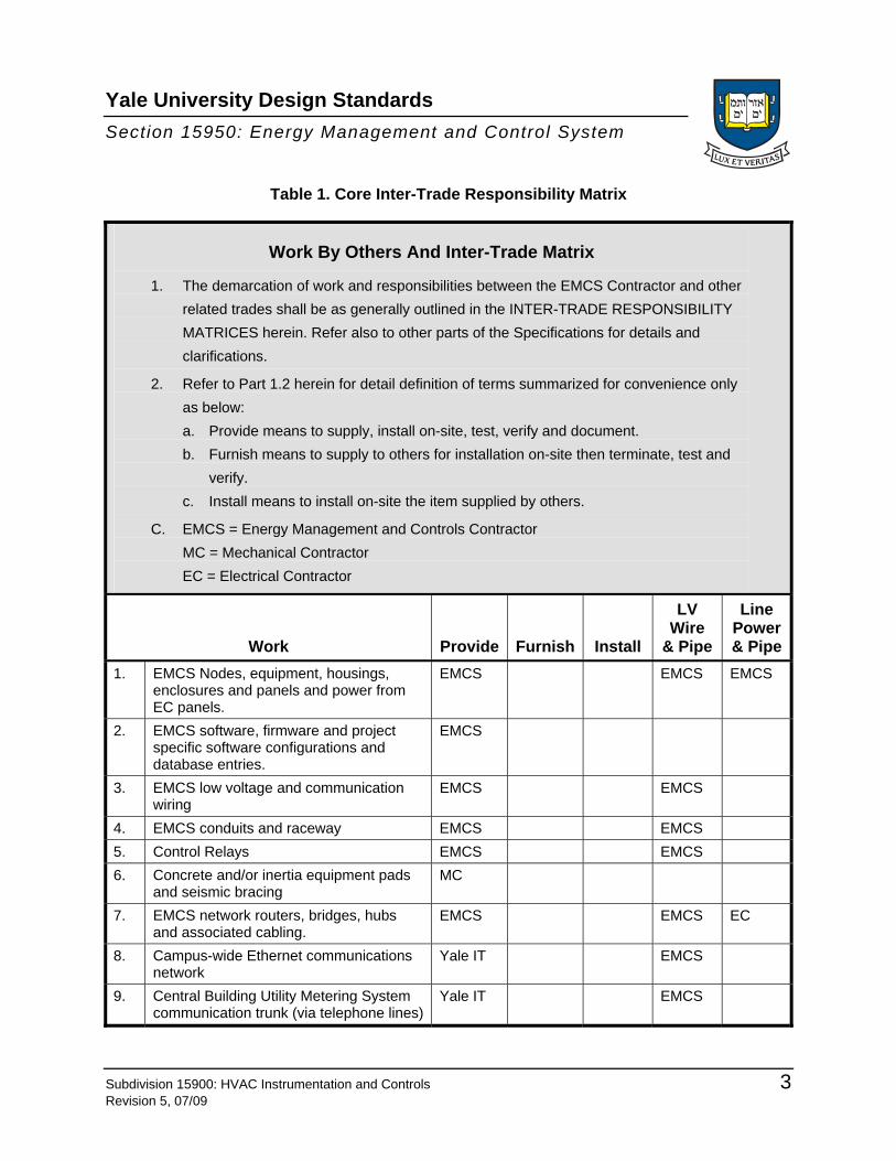
Table 1. Core Inter-Trade Responsibility Matrix
Work By Others And Inter-Trade Matrix
1. The demarcation of work and responsibilities between the EMCS Contractor and other related trades shall be as generally outlined in the INTER-TRADE RESPONSIBILITY MATRICES herein. Refer also to other parts of the Specifications for details and clarifications.
2. Refer to Part 1.2 herein for detail definition of terms summarized for convenience only as below: a. Provide means to supply, install on-site, test, verify and document. b. Furnish means to supply to others for installation on-site then terminate, test and
verify. c. Install means to install on-site the item supplied by others.
C. EMCS = Energy Management and Controls Contractor MC = Mechanical Contractor EC = Electrical Contractor
Work Provide Furnish Install
LV Wire
& Pipe
Line Power & Pipe
1. EMCS Nodes, equipment, housings, enclosures and panels and power from EC panels.
EMCS EMCS EMCS
2. EMCS software, firmware and project specific software configurations and database entries.
EMCS
3. EMCS low voltage and communication wiring
EMCS EMCS
4. EMCS conduits and raceway EMCS EMCS 5. Control Relays EMCS EMCS 6. Concrete and/or inertia equipment pads
and seismic bracing MC
7. EMCS network routers, bridges, hubs and associated cabling.
EMCS EMCS EC
8. Campus-wide Ethernet communications network
Yale IT EMCS
9. Central Building Utility Metering System communication trunk (via telephone lines)
Yale IT EMCS

Yale University Design Standards Section 15950: Energy Management and Control System
Subdivision 15900: HVAC Instrumentation and Controls 4 Revision 5, 07/09
Table 1. Core Inter-Trade Responsibility Matrix—Continued
Building Controls and Lighting Controls Inter-Trade Responsibility Matrix
Work Provide Furnish Install
LV Wire
& Pipe
Line Power & Pipe
10. Temperature Control Panels EMCS EMCS EC 11. VAV Box controller and Terminal Unit
Nodes EMCS MC EMCS EC
12. Automatic dampers EMCS MC EMCS EC 13. Manual valves MC 14. Automatic valves EMCS MC EMCS EC 15. VAV boxes MC 16. Pipe insertion devices and taps
including thermowells, flow and pressure stations, etc.
EMCS MC EMCS EC
17. Current Switches. EMCS EMCS 18. Power Distribution System monitoring
interfaces EC EC EC EC
19. Central Building Utility Metering System EMCS EC 20. EMCS interface with Chiller control
package EMCS EMCS EC
21. Chiller controls interface to EMCS (N2, BACNet)
MC EMCS EC
22. Chiller and Boiler Flow Switches MC EMCS 23. Boiler control package MC EMCS EC 24. Water treatment system MC MC EC 25. Variable Frequency Drives EMCS EC EMCS EC 26. Refrigerant monitors MC EMCS EMCS EC 27. Isolation room monitors EMCS EMCS EC 28. Fume hood controls EMCS EMCS EC 29. Medical gas panels MC EMCS EC 30. Laboratory Air Valves EMCS MC EMCS EC 31. Computer Room A/C Unit site-mounted
controls MC EMCS EMCS EC
32. Fan Coil Unit controls EMCS EMCS EC 33. Unit Heater controls EMCS EMCS EC 34. Packaged Rooftop Unit (RTU) space
mounted controls MC EMCS EMCS EC

Yale University Design Standards Section 15950: Energy Management and Control System
Subdivision 15900: HVAC Instrumentation and Controls 5 Revision 5, 07/09
Table 1. Core Inter-Trade Responsibility Matrix—Continued
Building Controls and Lighting Controls Inter-Trade Responsibility Matrix
Work Provide Furnish Install
LV Wire
& Pipe
Line Power & Pipe
35. Packaged RTU factory-mounted controls MC EMCS EC 36. Packaged RTU field-mounted controls EMCS EMCS EC 37. Cooling Tower Vibration Switches MC EMCS EC 38. Cooling Tower Level Control Devices MC EC EC 39. Cooling Tower makeup water control
devices MC EC EC
40. Starters, HOA switches EC EMCS EC 41. Control damper actuators EMCS EMCS EC 42. Tenant Meters EMCS EMCS EC
NOTE: The Design Engineer shall specify any other job specific requirements for the EMCS contractor.
b. Division 16000 Contractor shall provide:
(1) The Division 16000 contractor shall provide for adequate task lighting above each Direct Digital Controller (DDC) cabinets and other associated panels to provide for unit service, by adding light fixtures if necessary, regardless of whether specifically shown on the drawings or not.
(2) Dedicated circuit breakers for DDC or other associated field cabinets that shall have protective guards preventing accidental (manual) switching off the designated circuit breakers.
(3) Dedicated and tagged circuits from the alternate power service wired to all DDC panels. Location of these panels on the contract drawings are the responsibility of the design engineer.
(4) All labor and material to mount, power, and connect VFDs to appropriate motors.

Yale University Design Standards Section 15950: Energy Management and Control System
Subdivision 15900: HVAC Instrumentation and Controls 6 Revision 5, 07/09
3. System Description
a. Scope (1) Provide labor, materials, services, equipment and engineering necessary for
a complete and operational Energy Management and Control System (EMCS) as indicated on Contract Drawings and specified herein, including but NOT limited to the following:
(a) Controls for air handling systems including air flow control for laboratories, supply fans, heating coils, humidifiers, return fans, exhaust fans, exhaust hoods, dampers, and VAV boxes, etc., as per the specifications Sections 15000 & 16000, mechanical and electrical drawings.
(b) Controls for pressurization and airflow including variable frequency drives, dampers, static pressure and flow stations and pressure control valves, etc.
(c) Controls for hydronic systems including heat exchangers, chilled water system, chilled water differential pressure control, coils, pumps, condensate, and heat recovery, etc., as per the specifications by Division 15000 & 16000, and mechanical and electrical drawings.
(d) Furnishing and installing Central Building Utility Metering System (CBUMS) and chilled water differential pressure control valve(s) as shown on the contract drawings.
(e) Furnishing and installing laboratory airflow and hood control systems approved by Yale University Facilities Engineering Department as per the contract documentation .
(f) Complete system engineering, software generation, work- station graphics and project management of controls installation including consultations of control sequences with Yale University Systems Engineering before control software generation.

Yale University Design Standards Section 15950: Energy Management and Control System
Subdivision 15900: HVAC Instrumentation and Controls 7 Revision 5, 07/09
(2) Provide complete electrical installation of controls including:
(a) Connection of field sensors, DDC panels, and field controllers.
(b) Connection of all DDC field communication wiring. Connection of building level controllers to the Yale Network as per instructions by Yale Facilities Systems Engineering department.
(c) Extension of dedicated 120VAC control circuit power feeds from control cabinets to field devices (e.g. valves, dampers, VAV box digital controllers, and fan-coil digital controllers).
(d) All junction boxes for DDC wiring, raceways, and other components of the installations (circuit breakers) shall be marked blue for easy identification by the controls mechanics.
(e) Ethernet wiring shall be installed by Yale Telecommunications; initiated by the Yale Project Manager with a START request. Telephone lines as means of communication for control devices is not acceptable.
(3) Provide the services of control manufacturer’s representative to be on-site during the entire time that the start up, testing and balancing procedures, detailed in this specification, takes place. Representative shall be part of manufacturer’s service organization and shall be skilled in the adjustment and calibration of all control devices as well as being capable of modifying and checking system software. Perform calibration, system validation and startup, and acceptance testing in presence of Owner's representative and/or Systems Engineer. Provide 15 days notice before acceptance test. Notice shall certify that system is complete and operates as required by Contract Documents. When system performance is deemed satisfactory, system parts shall be accepted for beneficial use and the one year vendor’s warranty shall begin.
(4) Note any additional requirements noted elsewhere in this specification.
(5) Provide DDC system supplier's warranty of performance of entire system, including electric components, as required by Contract documents. Performance and components requirements are established by control sequences and diagrams on Drawings and by this Section.

Yale University Design Standards Section 15950: Energy Management and Control System
Subdivision 15900: HVAC Instrumentation and Controls 8 Revision 5, 07/09
(6) DDC system shall perform all sequences of operation, which may be listed on control drawings or attached to this specification. Controls supplier shall provide all devices necessary to completely perform sequences whether such devices are explicitly shown on the drawings, specified, or not shown or specified. A complete functioning system should be supplied requiring no manual intervention. This should include sequences plus any necessary shutdown sequences to inhibit alarms and nuisance system messages and still leave the system in a safe reporting position.
b. DDC Interfaces (1) Communication on the campus level is via the campus network. Any
device connected to this network must be approved by Yale Facilities Systems Engineering and by Yale Facilities Information Services departments.
(2) Communication to third party controllers such as VFDs, fume hood controllers, package unit controllers, etc., if specified by the Engineer, should be Bacnet. JCI N2 acceptable for Metasys controlled systems.
(3) The Engineer shall consult with Yale Facilities Systems Engineering on available and supported interfaces and pre-selected communications and controls and automation systems for Yale installations.
(4) Yale approved interface drivers and protocols are:
(a) Within the building (2-4 wire serial interfaces) JCI N2 and Bacnet only. Bacnet on Arcnet is acceptable (ALC)
(b) On the Campus level Ethernet – Bacnet/IP
(c) Vendor proprietary protocol or OPC must be approved by Yale Facilities Systems Engineering.
4. Submittals a. The EMCS contractor shall submit within 60 days after award installation
drawings and control strategies for review.
b. Each submittal shall have a cover sheet with the following information provided: submittal ID number; date; project name, address, and title; FMS Contractor name, address and phone number; FMS Contractor project manager, quality control manager, and project engineer names and phone numbers.

Yale University Design Standards Section 15950: Energy Management and Control System
Subdivision 15900: HVAC Instrumentation and Controls 9 Revision 5, 07/09
c. Each submittal shall include the following information.
(1) EMCS riser diagram, showing all DDC controllers, operator workstations, network components, and network wiring.
(2) One-line schematics and system flow diagrams showing the location of all control devices.
(3) Points list for each DDC controller, including: Tag, Point Type, System Name, Object Name (Yale standard acronym), Expanded ID, Display Units, Controller Type, Address, Cable Destination, Module Type, Terminal ID, Panel, Slot Number, Reference Drawing, and Cable Number.
(4) Contractor’s own written description for each sequence of operations, to include the following:
(a) Sequences shall reference input/output and software parameters by name and description.
(b) The sequences of operations provided in the submittal by the EMCS Contractor shall represent the detailed analysis needed to create actual programming code from the design documents.
(c) Points shall be referenced by Yale acronym, including all software points such as programmable setpoints, range limits, time delays, and so forth. In general the point naming convention must follow a building-system outline – all points must have their building associated in their full point name.
(d) The sequence of operations shall cover normal operation and operation under the various alarm conditions applicable to that system.

Yale University Design Standards Section 15950: Energy Management and Control System
Subdivision 15900: HVAC Instrumentation and Controls 10 Revision 5, 07/09
(e) User interface functional outline. The outline shall include each display (graphics) screen to be provided, data to be displayed, and links to other screens. The outline must follow existing Yale Person Machine Interface (PMI) color-graphic screens. The outline level hierarchy shall start with the building name. Separate trees for floor controls and separate trees for major systems (heat exchangers, AHU’s, etc.). It must be easily identifiable which AHUs server which floors or parts of floors. Graphic links short cutting to major systems are encouraged – i.e. a link to an AHU graphic from a VAV graphic.
(5) Detailed Bill of Material list for each panel, identifying: quantity, part number, description, and associated options.
(6) Control Damper Schedules. This spreadsheet type schedule shall include a separate line for each damper and a column for each of the damper attributes, including: Code Number, Fail Position, Damper Type, Damper Operator, Blade Type, Bearing Type, Seals, Duct Size, Damper Size, Mounting, and Actuator Type.
(7) Control Valve Schedules. This spreadsheet type schedule shall include a separate line for each valve and a column for each of the valve attributes, including: Code Number, Configuration, Fail Position, Pipe Size, Valve Size, Body Configuration, Close off Pressure, Capacity, Valve CV, Calc CV, Design Pressure, Actual Pressure, and Actuator Type.
(8) Cataloged cut sheets of all equipment used. This includes, but is not limited to the following: DDC panels, peripherals, sensors, actuators, dampers, system components, and so forth.
(9) Range and scale information for all transmitters and sensors. This sheet shall clearly indicate one device and any applicable options. Where more than one device to be used is on a single sheet, submit two sheets, individually marked.
(10) Training course outlines (if required).
(11) Hardware data sheets for all operator workstations, local access panels, and portable operator terminals.

Yale University Design Standards Section 15950: Energy Management and Control System
Subdivision 15900: HVAC Instrumentation and Controls 11 Revision 5, 07/09
(12) EMCS Contractor shall not order material or begin fabrication or field installation until receiving authorization to proceed in the form of an approved submittal. EMCS Contractor shall be solely responsible for the removal and replacement of any item not approved by submittal at no cost to the Owner.
d. For jobs contracted directly by Yale with their submittal, the contractor shall submit a detailed and guaranteed job schedule to Yale Project Manager for approval. The "schedule" shall include, but not be limited to, start and completion dates for all activities during design, engineering, installation, software generation, commissioning, and turnover phases of the project. The contractor shall take full responsibility for non-compliance with the approved schedule. The final schedule shall be submitted to Yale no later than twenty (20) days after the contract award date.
e. Yale University does not require submittals of Factory Test results since the controls and automation systems for Yale installations are presumed to be standard products, tested, and field operating for at least one year. In case the proposed system does not meet the above requirements, the EMCS contractor MUST contact Yale Facilities Systems Engineering for installation approval upon satisfying the conditions set forward by Yale Facilities Systems Engineering for installation of such system.
f. Prior to software generation, the EMCS contractor shall submit the following information for review to Yale Facilities Systems Engineering:
(1) Complete set of approved submittals.
(2) “Tree” outline of color graphics for the front-end Operator's Work Station (OWS).
(3) Samples of Trends and History standard reports on the front end OWS.
(4) List of alarm points, their limits, classification of alarms, associated alarm messages interlocks with devices to inhibit alarms, and other relevant alarm reporting features.
(5) Initial setpoint values for controlled variables and schedules.
(6) List of advisories for operators for manual control.

Yale University Design Standards Section 15950: Energy Management and Control System
Subdivision 15900: HVAC Instrumentation and Controls 12 Revision 5, 07/09
g. All devices on submittal shop drawings shall be identified by Yale acronyms. These identifiers shall also be used in description of operation, in control layouts, and on data sheets for ease in cross-referencing. Final control drawings shall be CAD generated in a format compatible with the AutoCAD system.
5. O&M Manuals Prior to final system acceptance an Operation and Maintenance Manual shall be generated to describe function and operation of all control system components and shall include operating and trouble-shooting procedures. Submit three (3) sets of each Manual. The Manual shall be easily understood, for use by the Yale Control Center (CC) personnel; shall show the total integrated control system; and shall include:
a. Include the following documentation in the Hardware Manual:
(1) General description and cut sheets for all components.
(2) Detailed wiring and installation illustrations and complete calibration procedures for each field and panel device.
(3) Complete trouble-shooting procedures and guidelines.
(4) Complete operating instructions for all systems.
(5) Maintenance Instructions: Document all maintenance and repair/replacement procedures.
(6) Calibration requirements and instructions.
b. Include the following documentation in the DDC Software Manual:
(1) Sequence of Operations.
(2) Program Listing of Software Source Code or Flow Chart Diagrams of Programming Objects.
(3) Printed listing of controller and operator workstation database files.
(4) Software Point Name Abbreviation List including point name with Yale acronym, Description, Controller Where Located, Point Type and Point ID.
(5) I/O Point List; Include Point Name (Yale acronym), Controller Location, Point Number, Control Device, Range and Span.
(6) Printouts of all; Reports, Group Listings and Alarm Messages.

Yale University Design Standards Section 15950: Energy Management and Control System
Subdivision 15900: HVAC Instrumentation and Controls 13 Revision 5, 07/09
c. It is the responsibility of the EMCS Contractor to assure that the Yale Customer Service Department has all current documentation regarding the installed EMCS. As part of this Scope of Work, the EMCS contractor, upon updating Yale Customer Service with current information, will issue a Letter of Compliance to the CM/GC, acknowledging that the Yale Physical Plant Department has all current information, in electronic format, regarding the following:
(1) System Engineering Manual.
(2) System Installation Manual.
(3) Programming Manual.
(4) Engineering and Troubleshooting Bulletins.
(5) Operator Workstation Software Manual.
(6) All other pertinent manuals published by the control system manufacturer.
d. All manuals shall be provided in hard copy format and on a single Compact Disk (CD) as part of an on-line documentation system through the operator workstation.
e. Record Drawings including sequences of operation.
f. Complete database and software program of system in suitable electronic format will be sent by the EMCS Contractor to the Yale Customer Service Department with a copy of the Letter of Transmittal sent to the GC/CM.
6. Warranty
a. Material The Control System shall be free from defects in material and material workmanship under normal use and service. If within thirty six (36) months from the date of completion any of the equipment herein described is defective in operation, workmanship or materials, it shall be replaced, repaired or adjusted at the option of the EMCS Contractor free of charge.

Yale University Design Standards Section 15950: Energy Management and Control System
Subdivision 15900: HVAC Instrumentation and Controls 14 Revision 5, 07/09
b. Installation (1) The Control System shall be free from defects in installation workmanship
for a period of twelve (12) months from acceptance. The EMCS Contractor shall, free of charge, correct any defects in workmanship within four (4) hours of notification by the Owner.
(2) During this guarantee period, the EMCS Contractor shall warrant the proper operation of the control system and implemented control strategies. During this twelve (12) month period, the performance of the controlled HVAC system associated algorithms shall be examined and verified by the EMCS Contractor and Yale. Any tuning, software corrections or enhancements to the application software algorithms installed for the project shall be made at the request of Yale and provided by the EMCS Contractor at no additional cost to the University.
c. Warranty Service Service technicians shall be dispatched to effect remedial action or to make enhancements within four (4) hours of being notified. Service shall be available 24 hours a day, 365 days a year.
d. Certification of Product Availability Furnish certificate from manufacturer of control system that expansion hardware and software shall be available for a minimum of seven (7) years from date of completion. Supply Yale with complete database of system on acceptable disks.
B. Products and Systems
1. Acceptable Manufacturers • Johnson Controls (Metasys) • Automated Logic (WebCTRL)

Yale University Design Standards Section 15950: Energy Management and Control System
Subdivision 15900: HVAC Instrumentation and Controls 15 Revision 5, 07/09
2. System Performance—Direct Digital Control (DDC) a. Control shall be performed by a field programmable, microprocessor based,
digital system controller that incorporates Direct Digital Control. The Direct Digital Controller shall provide all control and necessary energy management functions and provide for display and local adjustments via connection to a portable PC terminal.
b. Each major HVAC system shall have an individual dedicated controller controlling all functions of the HVAC system in a standalone mode in case of communications failure with the building controller, including time programs, etc.
c. The Direct Digital Controller shall perform its assigned control and energy management functions, including time schedules, as a stand-alone unit. Additionally, it shall be incorporated into the University EMCS Network. The EMCS Network communications is via campus Ethernet.
d. Communications at the Campus level, from the building controller to vendor specific front end Operator Work Station (OWS) is via industry standard protocols.
e. The Direct Digital Controller shall perform its full control and energy management functions, regardless of the condition of the Yale communications link. System shall be designed with maximum fault tolerance, such that the failure of one controller shall not disrupt communications to Work Stations or other controllers in the EMCS network. The stand alone capabilities shall include, but not be limited to:
(1) Closed loop control functions (P, PI, PID, Incremental, Floating, etc.), and cascading of control loops, scheduling, time profiles.
(2) Energy management functions including, but not limited to: scheduling, time programs, economizer control, supply air reset, supply water reset, adaptive optimal start, optimization functions, etc.
(3) Execution of programs written by the contractor to meet job specific requirements.
(4) Control processes shall be designed with the necessary data points to make setpoints, prop bands, etc adjustable without requiring download or system interruption.

Yale University Design Standards Section 15950: Energy Management and Control System
Subdivision 15900: HVAC Instrumentation and Controls 16 Revision 5, 07/09
(f) Control algorithms shall be available and resident in the building or local controller to permit proportional, integral, and derivative control modes in any combination to meet the needs of the application.
(g) The standard tolerances for Yale applications are +/-0.5 °F; +/-5% RH; +/- 0.2 in. w.c. static pressure; +/-1 psig, unless otherwise requested by the mechanical engineer and approved by Facilities Systems Engineering Department. Other control modes such as incremental, floating or two position, shall be available to adapt to job needs.
(h) All point names associated with control algorithms, including software point names, shall follow Yale University standard acronyms. All control loops shall be fully electronic.
(i) The EMCS shall be capable of performing all the energy management functions necessary to reduce energy consumption. These programs shall include, but not be limited to:
(1) Supply air reset using space load demand.
(2) Enthalpy is the preferred method of economizer control. Dry bulb may be acceptable with Yale Facilities System Engineering approval.
(3) Optimal start using an adaptive algorithm to prevent the need for manual adjustment of parameters.
(4) Facility and system specific algorithms as directed by Yale University Facilities Systems Engineering.
(5) A library of routines available in firmware must be capable of generating additional programs for specific requirements. These shall include, but not be limited to the following: chiller efficiency, boiler efficiency, seasonal and "dead band" control, VAV fan matching control, psychometric chart DX control, totalizing, holiday programming, etc.
(j) The DDC controller shall contain all necessary mathematics, logic, utility functions, standard energy calculations, and control functions in ROM to be available in any combination for programming the unit. All programming shall be from the designated Engineering Work Station. Programming routines available shall include, but not be limited to the following:
(1) Math Routines - Basic arithmetic, Boolean logic, relational logic, fixed formulas for psychometric calculations.

Yale University Design Standards Section 15950: Energy Management and Control System
Subdivision 15900: HVAC Instrumentation and Controls 17 Revision 5, 07/09
(2) Utility Routines - Process entry and exit, variable adjustments and output, alarm indication, power fail restart, local I/O interface.
(3) Control Routines - Signal compensation, loop control, energy conservation, timed programming.
(4) Final control programs shall be stored in non-volatile EEPROM or battery backed up RAM for up to 72 hours on power failure.
(5) In addition, all software programs shall be stored at the Engineering Work Station computer on the hard disk drive for review, modification and downloading to the controller in the field.
(k) The DDC controller shall contain in its program a non-destructive self-test procedure for testing memory and processor functions. Alarms shall be sent to the designated Work Stations for any abnormality within the processor, memory, as well as all analog point failure, and all program deviation alarms. All process and hardware variables shall be identified as being reliable or unreliable. When a calculation is required to use a value, sensed or calculated, which is identified as being unreliable, the calculation shall use a preprogrammed default value and the "unreliable status" shall be reported at the designated Work Stations.
3. Software a. Software generation shall follow standard Yale University sequences for heat
exchanger control, condensate alarming, psychometric chart control of DX systems, and reset schedules as approved by Yale Facilities System Engineering.
b. All device names (acronyms) shall follow Yale University standard naming conventions.
c. Software alarms shall be provided for analog deviation, run-time, utility services failure, space comfort range deviation, and additional alarms as directed by Yale University Facilities Systems Engineering.
d. Alarms shall report device location, software name, description, and criticality of alarm. Alarms shall report to the designated Work Stations and be logged on the alarm printer showing date and time of alarm.

Yale University Design Standards Section 15950: Energy Management and Control System
Subdivision 15900: HVAC Instrumentation and Controls 18 Revision 5, 07/09
e. All control software programs shall be loaded onto the hard disk drive of the Engineering Work Station. Also, the Yale Controls Systems Engineer will be given his or her own copy.
f. All networked controllers must be loadable form a remote connected workstation. It must not be necessary to go to a controller directly and load it, provided that it is on-line.
g. The PMI (Person Machine Interface) programs, such as color graphics, summaries, reports, etc., shall be developed by the contractor, approved by Yale Facilities Systems Engineering Department and loaded to the Engineering Work Station and controllers prior to the initial job walk-through. The controls vendor should be prepared to construct and re-construct the “front end” for reasonable improvements at no cost to Yale University.
4. Alarm Management Alarm management shall be provided to monitor, buffer, and direct alarm reports to operator devices and memory files. Each DDC panel shall perform distributed, independent alarm analysis and filtering to minimize operator interruptions due to non-critical alarms, to minimize network traffic, and to prevent alarms from being lost. At no time shall the DDC panel’s ability to report alarms be affected by either operator activity at a PC Workstation or local I/O device, or communications with other panels on the network.
a. Point Change Report Description All alarm or point change reports shall include the point’s English language description, and the time and date of occurrence.
b. Prioritization (1) The installer shall set up all system analog points with high and low alarm
limits. All digital system points shall be associated with a status feedback point and all exceptions shall be reported as alarms. The user shall be able to define the specific system reaction for each point. Alarms shall be prioritized and filtered to minimize nuisance reporting and to speed operator response to critical alarms.
(2) The user shall also be able to define under which conditions point changes need to be acknowledged by an operator, and/or sent to follow-up files for retrieval and analysis at a later date.

Yale University Design Standards Section 15950: Energy Management and Control System
Subdivision 15900: HVAC Instrumentation and Controls 19 Revision 5, 07/09
(3) The controls system will maintain an audit trail of operator activity. This will include but not be limited to - log in, log out, overrides, set point changes, schedule changes, system changes, downloads, uploads, and alarm activity.
c. Critical and Non-Critical Alarm Routing (1) Critical alarms shall be displayed at the designated workstations, printed at
the alarm printer, and paged to the on-duty maintenance person over the owner’s or vendor’s paging system, as requested by the owner. Alpha pages shall provide sufficient information to identify the equipment and the point in alarm and the time and date of occurrence.
(2) All other alarms shall be considered non-critical and shall be displayed and acknowledged before being sent to the alarm log.
d. Report Routing Alarm reports, messages, and files shall be directed to a Yale-defined list of operator devices, or devices used for archiving alarm information or reports. Alarms shall also be automatically directed to a default device in the event a primary device is found to be off-line.
e. Alarm Messages (1) In addition to the point’s descriptor and the time and date, the user shall be
able to print, display, or store an alarm message to more fully describe the alarm condition or direct operator response.
(2) Each standalone DDC panel shall be capable of storing an alarm message for each point.
f. Auto-Dial Alarm Management (1) Dial-up systems are unacceptable.
5. Color Graphics—Follow Yale Convention a. The graphics shall be able to display and provide animation based on real-time
data that is acquired, calculated, or entered.
b. Multiple graphic applications shall be able to execute at any one time on a single workstation.
c. All graphics shall be constructed from basic graphical objects.

Yale University Design Standards Section 15950: Energy Management and Control System
Subdivision 15900: HVAC Instrumentation and Controls 20 Revision 5, 07/09
d. Any basic object, any group of basic objects, or any symbol or group of symbols, shall be capable of being animated.
e. It shall be possible to change values (setpoints) and states in system controlled equipment from the color graphics screen.
f. A graphic editing tool shall be provided that allows for the creation and editing of graphic files. The graphic editor shall be capable of performing all drawing functions, defining all calculations to be executed as part of the graphic, defining all animations, and defining all runtime binding. It is not acceptable for separate programs to be required to do these various functions.
g. The EMCS system shall be provided with a very complete symbol library containing all of the basic symbols used to represent HVAC, FIRE, LIGHTING, CCTV, and SECURITY components of a typical EMCS system.
h. The EMCS Contractor shall fully configure the color graphics and plot all associated control/monitoring points on the screen. Copies of all color graphics screens shall be provided to Yale Facilities System Engineering for approval.
(1) The operator interface shall allow users to access the various system schematics, sections of the building or floors via a graphical penetration scheme, menu selection, or text-based commands. Floor plans shall display room numbers and each zone shall be color-coded. The operator shall be able to point and click on a room or zone of rooms (in the case of an air handler that serves more than one zone). The room or zone shall display an animated flow diagram of the mechanical equipment that serves that zone, with all control and monitoring points associated with that piece of equipment, including setpoints. Setpoints shall be overridden or modified from this screen.
(2) At the discretion of Yale Facilities Systems Engineering, a tabular format may be used for presentation of space data.
i. Dynamic temperature values, humidity values, flow values, and status indication shall be shown in their actual respective locations, and shall automatically update to represent current conditions without operator intervention. Damper and valve positions, air and water flow shall be animated and shall represent actual, current conditions.

Yale University Design Standards Section 15950: Energy Management and Control System
Subdivision 15900: HVAC Instrumentation and Controls 21 Revision 5, 07/09
j. The windowing environment of the PC Operator Workstation shall allow the user to simultaneously view several graphics at the same time to analyze total building operation, or to allow the display of a graphic associated with an alarm to be viewed without interrupting work in progress.
k. Any point in a state of alarm shall change the color of its symbol to red until it is no longer in alarm.
l. At the discretion of Yale Facilities Systems Engineering, a tabular format may be used for presentation of space data.
m. With every analog re-settable value their setpoint shall be also displayed on the screen.
6. Historical Trending and Data Collection a. Each Building Controller shall store trend and point history data for all analog
and digital inputs and outputs, as follows:
(1) Any point, physical or calculated, may be designated for trending. Three methods of collection shall be allowed: • Defined time interval • Upon a change of value • Whenever a value is out of range
(2) Each network controller shall have a dedicated RAM-based buffer for trend data. In the case of a system controller, it must have at least 1 MB of dedicated storage (ALC). For a building level controller it must have at least 128 MB of storage data for operations and trends. A building controller almost must have at least 50% spare capacity for expansion.
b. Trend and change of value data shall be stored within the controller and then uploaded to the trend database(s). Uploads shall occur based upon one of the following: user-defined interval, manual command, when the trend buffers are full, or scheduled.
c. The system shall provide a configurable data storage subsystem for the collection of historical data. Data is stored in SQL database format.
d. To enable users to easily access stored data, the system shall provide the capability to store historical data in more than one file system (i.e., removable media, separate hard drives, or a remote network file system.

Yale University Design Standards Section 15950: Energy Management and Control System
Subdivision 15900: HVAC Instrumentation and Controls 22 Revision 5, 07/09
e. Provide a trend viewing utility that shall have access to all database points.
f. Provide database access through an Open Database Connectivity (ODBC) interface – a standard Application Programming Interface (API) for accessing data from relational databases.
g. It shall be possible to retrieve any historical database point for use in displays and reports by specifying the point name.
h. The trend viewing utility shall have the capability to view up to 32 data sources at one time in a tabular or graphical format.
i. Graphic displays shall be able to be single or stacked graphs with on-line selectable display characteristics, such as ranging, color, and plot style.
j. It shall be possible to display trend data in histogram (X-Y plots) format as well as area and bar graphs.
k. Display magnitude and units shall both be selectable by the operator at any time without reconfiguring the processing or collection of data. This is a zoom capability.
l. Display magnitude shall automatically be scaled to show full graphic resolution of the data being displayed. This function shall also be operator selectable.
m. The display range shall consist of magnitude and units fields. The units are seconds, minutes, hours, days, and months.
n. Provide a wild card capability when specifying a display range for data retrieval within the historical database. Wild carding shall allow the user to easily specify relative time based date ranges for the retrieval of data.
o. A time offset capability shall be available to assist in a user’s analysis. The offset visually shifts the data being displayed to allow a user to concurrently view information without having to scroll the display.
p. The system shall be capable of printing a hard copy record of the trends as they are displayed on the workstation.
q. Prior to system acceptance, the EMCS contractor shall initiate a minimum of 24-hour trends for every connected point to the EMCS. These trends shall be used by the operators to diagnose start-up and operational problems. Additionally, the EMCS shall be capable of generating longer-term trend logs to diagnose adverse long-term trends.

Yale University Design Standards Section 15950: Energy Management and Control System
Subdivision 15900: HVAC Instrumentation and Controls 23 Revision 5, 07/09
7. Sequence of Operation a. The EMCS contractor shall develop their own written description for each
sequence of operations, to include the following:
(1) Sequences shall reference input/output and software parameters by name and description. Use actual system point names in sequences.
(2) The sequences of operations developed by the EMCS Contractor shall represent the detailed analysis needed to create actual programming code from the design documents.
(3) Points shall be referenced by Yale acronym, including all software points such as programmable setpoints, range limits, time delays, and so forth.
(4) The sequence of operations shall cover normal operation and operation under the various alarm conditions applicable to that system.
b. Prior to loading the software the control algorithms must be approved by the Engineer, Yale Project Manager and Yale Facilities Systems Engineering.
NOTE: The design engineer is to provide detailed sequences of operation for all equipment that shall enable the EMCS contractor to develop their own functional sequences for generation of software. These design sequences can be detailed here, or more preferably on the contract control drawings.
8. Redundancy a. Sufficient redundancy shall be provided such that operation shall continue
unimpaired given the failure of any single DDC unit. Failure of any point module shall not impair functions of other modules, loops, DDC, OWS, etc.
b. Field equipment (i.e. pump) operation shall continue unimpaired given the complete failure of communications between distributed DDC and Designated Work Stations. Procedures for system shutdown and recovery of failed DDCs shall be provided by the EMCS contractor.
9. Position of Failed Equipment The controlled equipment shall remain in the last position in case of system failure, or as specified by the Engineer.

Yale University Design Standards Section 15950: Energy Management and Control System
Subdivision 15900: HVAC Instrumentation and Controls 24 Revision 5, 07/09
10. Diagnostics The EMCS shall provide the operator with information, which shall allow efficient operation by identification of unfavorable trends, e.g. system performance below normal, equipment not operating as expected, etc. Tuning screens shall aid the operators in tuning individual PID loops from the designated Work Stations.
11. Digital Communication Interface—Drivers a. Necessary hardware, software and application programming shall be provided
to interface to third party systems if specified for the job.
b. All points from these systems shall be mapped over to the DDC system.
C. Component Specification 1. Remote DDC Units
a. Remote DDC units shall accommodate all points specified by the Engineer.
b. The DDCs shall be located near the highest concentration of field points. The location shall be approved by Yale Facilities Systems Engineering Department.
c. The DDC controller shall be enclosed in a cabinet. The cabinet shall be constructed such that it can be mounted and electrical terminations made during the installation phase of the project, without the control electronics being installed. The cabinet shall be NEMA rated for its location and expected environment. The DDC electronics shall be modular and shall be added during the commissioning phase of the project. The DDC cabinet and any associated units, for example Field Equipment Units (FEUs) shall be provided with a master keyed lock, keys turned over to Yale Physical Plant.
d. The EMCS shall also be expandable by adding additional field interface units that operate through the processor in the DDC Controller. The processor in the DDC shall be able to manage remote field interface units, expanding its control loop and energy management point capacity.
e. The DDCs shall be stand alone, with CPU's, clock, and communication interfaces.
f. The DDCs shall contain point modules, interface modules, etc. for the connected field equipment and third party controllers.
g. Control, communication and power circuits shall be individually electronically isolated to protect against transients, spikes, and power surges.

Yale University Design Standards Section 15950: Energy Management and Control System
Subdivision 15900: HVAC Instrumentation and Controls 25 Revision 5, 07/09
h. The DDC shall be an approved UL system, with a UL listing as a Signaling System.
2. Field Instruments
a. Dampers and Damper Actuators (1) Automatic dampers shall be of modular sections. Damper frames and
blades shall be constructed of either galvanized steel or aluminum. Maximum blade length in any section shall be 48”. Damper blades shall be 16-gauge minimum and shall not exceed six (6) inches in width. Damper frames shall be 16-gauge minimum hat channel type with corner bracing. Additional stiffening or bracing shall be provided for any section exceeding 48” in height. All damper bearings shall be made of stainless steel or oil-impregnated bronze. Dampers shall be tight closing, low leakage type, with synthetic elastomer seals on the blade edges and flexible stainless steel side seals. Damper blade and seal material must be compatible with use. Dampers of 48”x48” size shall not leak in excess of 8.5 CFM per square foot when closed against 4” w.c. static pressure when tested in accordance with AMCA Std. 500.
(2) Two-position dampers shall be parallel blade, and modulating dampers shall be opposed blade.
(3) Dampers shall be Class II with leakage not to exceed 10 CFM per square foot at 1" W.G.
(4) Acceptable manufacturers are: Johnson Controls D-1300, Ruskin CD36, and Vent Products 5800. Other models must be approved by Systems Engineering.
b. Smoke Dampers and Actuators (1) Smoke dampers shall be of modular sections. Bearings shall be self
lubricating porous bronze. Side seals shall be spring loaded stainless steel. Blade seals shall be rated to withstand 250 DEGF. The smoke damper sections shall be specified under Division 15000.
(2) Each smoke damper shall be UL555S listed and bear UL label attesting to same.
(3) Leakage rating under UL555S shall be leakage Class II (10 CFM per square foot at 1" W.G.).

Yale University Design Standards Section 15950: Energy Management and Control System
Subdivision 15900: HVAC Instrumentation and Controls 26 Revision 5, 07/09
(4) Appropriate electric actuator shall meet all applicable UL555S qualifications for both dampers and actuators.
(5) Smoke dampers shall be supplied with the motor factory mounted, with end switches to signal open/close position.
(6) Acceptable manufacturers are: Johnson Controls SD-1300 or Ruskin SD-36. Other models must be approved by Systems Engineering.
c. Damper Actuators (1) Damper and valve actuators shall be electronic and will be direct shaft
mount.
(2) Modulating and two-position actuators shall be provided as required by the sequence of operations. Damper sections shall be sized based on actuator manufacturer’s recommendations for face velocity, differential pressure and damper type. The actuator mounting arrangement and spring return feature shall permit normally open or normally closed positions of the dampers, as required. All actuators (except terminal units) shall be furnished with mechanical spring return unless otherwise specified in the sequences of operations. All actuators shall have external adjustable stops to limit the travel in either direction, and a gear release to allow manual positioning.
(3) Modulating actuators shall accept 24 VAC or VDC power supply, consume no more than 15 VA, and be UL listed. Each damper bank (outdoor air, return air and exhaust air) will have a separate output from the controller. The control signal shall be 0-10 VDC or 4-20 mA, and the actuator shall provide a clamp position feedback signal of 0-10 VDC or 4-20 mA. The feedback signal shall be independent of the input signal and may be used to parallel other actuators and provide true position indication. The feedback signal of one damper actuator for each separately controlled damper shall be wired back to a terminal strip in the control panel for trouble-shooting purposes.

Yale University Design Standards Section 15950: Energy Management and Control System
Subdivision 15900: HVAC Instrumentation and Controls 27 Revision 5, 07/09
(4) Two-position or open/closed actuators shall accept 24 or 120 VAC power supply and be UL listed. Isolation, smoke, exhaust fan, and other dampers, as specified in the sequence of operations, shall be furnished with adjustable end switches to indicate open/closed position or be hard wired to start/stop associated fan. Two-position actuators, as specified in sequences of operations as “quick acting,” shall move full stroke within 20 seconds. All smoke damper actuators shall be quick acting.
(5) All actuators shall include a feedback mechanism sensing actual position to provide a positive feedback to the DDC. Feedback sensed from controller command output is not acceptable. Exceptions must be approved by Yale Systems Engineering. All actuators shall be labeled with software name.
(6) Acceptable manufacturers: Johnson Controls, Belimo, Neptronic. Other models must be approved by Plant Engineering.
d. Automatic Control Valves (1) All control valves required by the control system are to be provided by the
EMCS Contractor for installation by the Division 15000 Contractor. Valves shall fail to normally open or closed position as specified. Modulating single seated straight through valves for chilled water, hot water, or steam service shall be provided with equal percentage contoured throttling plugs. Use v-port ball valves as preference.
(2) All control valves shall be provided with electric actuators. All actuators shall include a feedback mechanism sensing actual position to provide a positive feedback to the DDC. Feedback sensed from controller command output is not acceptable. Exceptions must be approved by Yale Systems Engineering. All actuators shall be labeled with software name.
(3) Valves 2" and smaller shall be ANSI class 250, brass body, or cast iron screwed connections. Valves larger than 2" shall be ANSI class 125, cast iron body, flanged connections. Stems shall be stainless steel with packing guaranteed against leakage for one year past contractual warranty with only packing nut adjustment required. The valve ANSI class must be correct for the application. This section does not supersede the requirement for the engineer to choose the correct valves for the design application.
Yale University Design Standards Section 15950: Energy Management and Control System
Subdivision 15900: HVAC Instrumentation and Controls 28 Revision 5, 07/09
(4) Valve schedule shall indicate capacity, pressure drop, size, and CV rating. All control valves shall operate smoothly without hunting or cycling and be capable of operating within the temperature and pressure range of the controlled fluid without leakage through the packing.
(5) Where control valves are shown or described in the sequence of operations to operate in sequence with other valves, dampers, or controlled devices, valves shall be either hardware or software sequenced to achieve the required sequence. Each sequenced valve shall have a separate output from the controller.
(6) Maximum pressure drop across the control valves shall be 5 psi.
(7) Acceptable manufacturers: Johnson Controls, Belimo, Warren. Other models must be approved by Yale Systems Engineering.
(8) Thermostatic fin tube radiation control valves shall be an assembly of a valve body and self-contained actuator top with remote mounted sensor. Actuator shall be replaceable without removal of valve body from piping. Actuator shall have a built-in set-point dial.
(a) Valve and actuator shall be Honeywell-Braukmann Model V110D valve with T104F series actuator, or models approved by Yale Systems Engineering.
(b) All required accessory pieces for remote mounting of sensor bulb shall be included.
e. Device Feedback Exceptions (1) Waiver of hardware feedback requirements for HVAC devices serving
individual isolated zones - where the controlled variable sensors are in a close proximity to the device (coil) - may be made by approval of Systems Engineering. Such devices include valves, dampers for fan-coil units VAV boxes, and unit heaters.
(2) In those instances where exceptions are made, the controlled variable (i.e. discharge air temp) shall provide the feedback indication.
f. Thermostats Not used in this specification. The use of pneumatic thermostats must be pre-approved by Yale Systems Engineering.

Yale University Design Standards Section 15950: Energy Management and Control System
Subdivision 15900: HVAC Instrumentation and Controls 29 Revision 5, 07/09
g. Low Temperature Detection (1) Low temperature detection thermostats shall be DPST, snap acting contacts
rated for 16 amps at 120VAC, or SPST with a dedicated 2-pole relay with manual reset. One set of N.C. contacts shall be hard wired to stop the protected coil's fan and the second set of contacts for alarm input to the DDC.
(2) Thermostat capillary shall have a minimum sensitive length of 20 feet, and shall be installed in a serpentine fashion a maximum of 18 inches downstream of the coil it is protecting. For coils less than 10 sq. ft., shorter capillaries shall be acceptable. Thermostats shall activate if any 2 inch section of capillary is below setpoint.
(3) Install one thermostat per 20 square feet of coil to be protected. Multiple thermostats shall be electrically wired in series.
(4) All low temperature detectors shall be labeled with software name.
(5) Acceptable manufacturers: Johnson Controls A70, Honeywell. Other models must be approved by Systems Engineering.
h. Low Steam Pressure Switch (1) Low steam pressure switches shall be 0 to 15 PSIG range, SPST with
contacts opening on pressure decrease, snap acting with automatic reset.
(2) Switches shall be supplied with siphon "pig tail".
(3) All low steam pressure switches shall be labeled with software name.
(4) Acceptable manufacturers: Johnson Controls. Other models must be approved by Systems Engineering.
i. Temperature Sensors (1) All temperature sensors shall be resistance temperature devices (RTDs)
having an accuracy of not less than 1% across full scale range. Sensors shall be nickel wound with a reference resistance of 1000 ohms.
(2) All sensors shall be labeled with software name.
j. Space Temperature Sensors (1) Room sensors shall be constructed for either surface or wallbox mounting.
(2) Room sensors shall have the following options when specified:

Yale University Design Standards Section 15950: Energy Management and Control System
Subdivision 15900: HVAC Instrumentation and Controls 30 Revision 5, 07/09
(a) Setpoint reset slide switch providing a +/- 2 degree (adjustable) range with a 6 degree deadband between heating and cooling set-points. The nominal heating set-point should be 68 and the cooling 74.
(b) Common heating/cooling setpoint slide switches.
(c) A momentary override request push button for activation of after-hours operation.
(d) Digital display of temperature and or set point(s).
(3) Acceptable Manufacturers: Johnson Controls TE Metastat, ALC RS series, or Hycal. Other models must be approved by Systems Engineering.
k. Duct Temperature Sensors (1) Duct mount sensors shall mount in an electrical box through a hole in the
duct, and be positioned so as to be easily accessible for repair or replacement.
(2) Duct sensors shall be insertion type and constructed as a complete assembly, including lock nut and mounting plate.
(3) For outdoor air duct applications, a weatherproof NEMA 3R mounting box with weatherproof cover and gasket shall be used.
(4) For ductwork greater in any dimension than 48 inches and/or where air temperature stratification exists, an averaging sensor with multiple sensing points shall be used. Capillary supports at the sides of the duct shall be provided to support the sensing string.
(5) Acceptable Manufacturers: Johnson Controls TE Metastat, ACI, BAPI or Hycal. Other models must be approved by Systems Engineering.
l. Well Insertion Temperature Sensors (1) When thermowells are required, the sensor and well shall be supplied as a
complete assembly, including well head and Greenfield fitting.
(2) Thermowells shall be stainless steel pressure rated and constructed in accordance with the system working pressure. Brass thermal wells are unacceptable.
(3) Condensate temperature sensors shall be provided with stainless steel wells and rated for operating temperatures up to 550°F.

Yale University Design Standards Section 15950: Energy Management and Control System
Subdivision 15900: HVAC Instrumentation and Controls 31 Revision 5, 07/09
(4) Thermowells and sensors shall be mounted in a threadolet or 1/2” NFT saddle and allow easy access to the sensor for repair or replacement.
(5) Thermowells shall be constructed of 316 stainless steel.
(6) Acceptable Manufacturers: Johnson Controls TE, ACI, BAPI or Hycal. Other models must be approved by Systems Engineering.
m. Humidity Sensors (1) The sensor shall be a solid state type, relative humidity sensor of the Bulk
Polymer Design. The sensor element shall resist service contamination.
(2) The humidity transmitter shall be equipped with non-interactive span and zero adjustments, a 2-wire isolated loop powered, 4-20 mA, or 0-10V 0-100% linear proportional output.
(3) The typical humidity transmitter shall have +/-5% accuracy on a range scale. Where applicable, a +/- 2% accuracy shall be used – vivarium, cultural properties, etc.
(4) Outside air relative humidity sensors shall be installed with a rain proof, perforated cover. The transmitter shall be installed in a NEMA 3R enclosure with Sealtite fittings and stainless steel bushings.
(5) A single point humidity calibrator shall be provided, if required, for field calibration. Transmitters shall be shipped factory pre-calibrated.
(6) Duct type sensing probes shall be constructed of 304 stainless steel, and shall be equipped with a neoprene grommet, bushings, and a mounting bracket.
(7) Acceptable Manufacturers: Johnson Controls, Veris Industries, and Vaisala. Other models must be approved by Systems Engineering.

Yale University Design Standards Section 15950: Energy Management and Control System
Subdivision 15900: HVAC Instrumentation and Controls 32 Revision 5, 07/09
n. Differential Pressure Transmitters (Air/Air)
(1) General Air and Water Pressure Transmitter Requirements (a) Pressure transmitters shall be constructed to withstand 100% pressure
over-range without damage, and to hold calibrated accuracy when subject to a momentary 40% over-range input.
(b) Pressure transmitters shall transmit a 0 to 5 VDC, 0 to 10 VDC, or 4 to 20 mA output signal.
(c) Differential pressure transmitters used for flow measurement shall be sized to the flow sensing device, and shall be supplied with Tee fittings and shut-off valves in the high and low sensing pick-up lines to allow the balancing Contractor and Owner permanent, easy-to-use connection.
(d) A minimum of a NEMA 1 housing shall be provided for the transmitter. Transmitters shall be located in accessible local control panels wherever possible.
(2) Low Differential Water Pressure Applications (0” - 20” w.c.) (a) The differential pressure transmitter shall be of industrial quality and
transmit a linear, 4 to 20 mA or 0-10V output in response to variation of flow meter differential pressure or water pressure sensing points.
(b) The differential pressure transmitter shall have non-interactive zero and span adjustments that are adjustable from the outside cover and meet the following performance specifications:
• .01-20” w.c. input differential pressure range. • 4-20 mA or o-10V output. • Maintain accuracy up to 20 to 1 ratio turndown. • Reference Accuracy: +0.2% of full span.

Yale University Design Standards Section 15950: Energy Management and Control System
Subdivision 15900: HVAC Instrumentation and Controls 33 Revision 5, 07/09
(c) Acceptable Manufacturers: Setra, Veris and Mamac.
(3) Medium to High Differential Hot Water Pressure Applications (Over 21” W.C.) (a) The differential pressure transmitter shall meet the low pressure
transmitter specifications with the following exceptions:
• Differential pressure range 10” w.c. To 300 PSI. • Reference Accuracy: +1% of full span (includes non-linearity,
hysteresis, and repeatability).
(b) Standalone pressure transmitters shall be mounted in a bypass valve assembly panel. The panel shall be constructed to NEMA 1 standards. The transmitter shall be installed in the panel with high and low connections piped and valved. Air bleed units, bypass valves, and compression fittings shall be provided.
(c) Acceptable Manufacturers: Setra and Veris.
(4) Building Differential Air Pressure Applications (-1” to +1” w.c.) (a) The differential pressure transmitter shall be of industrial quality and
transmit a linear, 4 to 20 mA or 0-10V output in response to variation of differential pressure or air pressure sensing points.
(b) The differential pressure transmitter shall have non-interactive zero and span adjustments that are adjustable from the outside cover and meet the following performance specifications:
• -1.00 to +1.00 w.c. input differential pressure ranges. (Select range appropriate for system application)
• 4-20 mA or 0-10V output. • Maintain accuracy up to 20 to 1 ratio turndown. • Reference Accuracy: +0.2% of full span.

Yale University Design Standards Section 15950: Energy Management and Control System
Subdivision 15900: HVAC Instrumentation and Controls 34 Revision 5, 07/09
(c) Acceptable Manufacturers: Johnson Controls, Veris and Setra. Other models must be approved by Systems Engineering.
(5) Low Differential Air Pressure Applications (0” to 5” w.c.) (a) The differential pressure transmitter shall be of industrial quality and
transmit a linear, 4 to 20 mA or 0-10V output in response to variation of differential pressure or air pressure sensing points.
(b) The differential pressure transmitter shall have non-interactive zero and span adjustments that are adjustable from the outside cover and meet the following performance specifications: • –1.00” to 5.00”) w.c. input differential pressure ranges. (Select
range appropriate for system application.) • 4-20 mA or 0-10V output. • Maintain accuracy up to 20 to 1 ratio turndown. • Reference Accuracy: +0.2% of full span.
(c) Acceptable Manufacturers: Johnson Controls, Veris, and Setra. Other models must be approved by Systems Engineering.
(6) Medium Differential Air Pressure Applications (5” to 21” w.c.) (a) The pressure transmitter shall be similar to the Low Air Pressure
Transmitter, except that the performance specifications are not as severe. Differential pressure transmitters shall be provided that meet the following performance requirements:
• Zero & span: (c/o F.S./Deg. F): .04% including linearity, hysteresis and repeatability.
• Accuracy: 1% F.S. (best straight line) Static Pressure Effect: 0.5% F.S. (to 100 PSIG).
• Thermal Effects: <+.033 F.S./Deg. F. Over 40°F. To 100°F. (calibrated at 70°F).

Yale University Design Standards Section 15950: Energy Management and Control System
Subdivision 15900: HVAC Instrumentation and Controls 35 Revision 5, 07/09
(b) Standalone pressure transmitters shall be mounted in a bypass valve assembly panel. The panel shall be constructed to NEMA 1 standards. The transmitter shall be installed in the panel with high and low connections piped and valved. Air bleed units, bypass valves, and compression fittings shall be provided.
(c) Acceptable manufacturers: Johnson Controls, Veris, and Setra. Other models must be approved by Systems Engineering.
0. Air Flow Monitoring
(1) Fan Inlet Air Flow Measuring Stations (a) At the inlet of each fan where shown on contract documents and near
the exit of the inlet sound trap, airflow traverse probes shall be provided that shall continuously monitor the fan air volumes and system velocity pressure.
(b) Each traverse probe shall be of a dual manifold, cylindrical, type 3003 extruded aluminum configuration, having an anodized finish to eliminate surface pitting and unnecessary air friction. The multiple total pressure manifold shall have sensors located along the stagnation plane of the approaching air flow. The manifold should not have forward projecting sensors into the air stream. The static pressure manifold shall incorporate dual offset static tops on the opposing sides of the averaging manifold so as to be insensitive to flow-angle variations of as much as + 20° in the approaching air stream.
(c) The airflow traverse probe shall not induce a measurable pressure drop, nor shall the sound level within the duct be amplified by its singular or multiple presence in the air stream. Each airflow measuring probe shall contain multiple total and static pressure sensors placed at equal distances along the probe length. The number of sensors on each probe and the quantity of probes utilized at each installation shall comply with the ASHRAE Standards for duct traversing.
(d) Air flow measuring stations shall be manufactured by Air Monitor Corp., Tek-Air Systems, Inc.,or Ebtron. Other models must be approved by Systems Engineering.
(2) Single Probe Air Flow Measuring Sensor

Yale University Design Standards Section 15950: Energy Management and Control System
Subdivision 15900: HVAC Instrumentation and Controls 36 Revision 5, 07/09
The single probe air flow measuring sensor shall be duct mounted with an adjustable sensor insertion length of up to eight inches. The transmitter shall produce a 4-20 mA or 0-10 VDC signal linear to air velocity. The sensor shall be a hot wire anemometer and utilize two temperature sensors and a heater element. The other sensor shall measure the downstream air temperature. The temperature differential shall be directly related to air flow velocity.
(3) Duct Air Flow Measuring Stations (a) Each device shall be designed and built to comply with, and provide
results in accordance with, accepted practice as defined for system testing in the ASHRAE Handbook of Fundamentals, as well as in the Industrial Ventilation Handbook.
(b) Traverse stations shall be connected to ductwork with bolts at flanges; stations shall be removable for cleaning. Each probe mounted within the station shall contain multiple total and static pressure sensors placed at equal distances (for rectangular ducts) or at concentric area centers (for circular ducts). The number of sensors provided with each flow station shall comply with the ASHRAE standards for duct traversing. The airflow traverse station shall produce a steady non-pulsating flow signal without need for correction factor or special calibration. The station shall be capable of measuring airflow through the station to within 2% of actual flow.
(c) The probes shall be installed perpendicular to the velocity profile gradient.
(d) Traverse probes or stations that incorporate honeycomb grid or tube type airflow straighteners are not acceptable.
(e) Traverse stations shall be constructed out of the same type material as the duct material.
(f) Total and static pressure manifolds shall terminate with external ports for connection to control tubing. An identification label shall be placed on each unit casing, listing model number, size, area, and specified airflow capacity.

Yale University Design Standards Section 15950: Energy Management and Control System
Subdivision 15900: HVAC Instrumentation and Controls 37 Revision 5, 07/09
(g) Installation Considerations
1 The maximum allowable pressure loss through the Flow and Static Pressure elements shall not exceed .065” w.c. at 1000 feet per minute, or .23” w.c. at 2000 feet per minute. Each unit shall measure the airflow rate within an accuracy of plus 2% as determined by U.S. – GSA certification tests, and shall contain a minimum of one total pressure sensor per 36 square inches of unit measuring area.
2 The units shall have a self-generated sound rating of less than NC40, and the sound level within the duct shall not be amplified nor shall additional sound be generated.
3 Where the stations are installed in insulated ducts, the airflow passage of the station shall be the same size as the inside airflow dimension of the duct. Station flanges shall be two inch to three inch to facilitate matching connecting ductwork.
4 Where control dampers are shown as part of the airflow measuring station, opposed blade precision controlled volume dampers integral to the station and complete with electric actuator and linkage shall be provided.
5 Stations shall be installed in strict accordance with the manufacturer’s published requirements, and in accordance with ASME Guidelines affecting non-standard approach conditions.
(h) Acceptable manufacturers: Air Monitor Corp., Tek-Air, and Ebtron. Other models must be approved by Systems Engineering.
(4) Static Pressure Traverse Probe (a) Duct static traverse probes shall be provided where required to monitor
duct static pressure. The probe shall contain multiple static pressure sensors located along exterior surface of the cylindrical probe.
(b) Acceptable manufacturers: Cleveland Controls. Other models must be approved by Systems Engineering.

Yale University Design Standards Section 15950: Energy Management and Control System
Subdivision 15900: HVAC Instrumentation and Controls 38 Revision 5, 07/09
(5) Shielded Static Air Probe A shielded static pressure probe, where shown on contract documents, shall be provided at each end of the building. The probe shall have multiple sensing ports, an impulse suppression chamber, and airflow shielding. A suitable probe for indoor and outdoor locations shall be provided.
p. Status And Safety Switches
(1) General Requirements Switches shall be provided to monitor equipment status, safety conditions, and generate alarms at the EMCS when a failure or abnormal condition occurs. Safety switches shall be provided with two sets of contacts and shall be interlock wired to shut down respective equipment.
(2) Current Sensing Switches (a) The current sensing switch shall be self-powered with solid state
circuitry and a dry contact output. It shall consist of a current transformer, a solid state current sensing circuit, adjustable trip point, solid state switch, SPDT relay, and an LED indicating the on or off status. A conductor of the load shall be passed through the window of the device. It shall accept over-current up to twice its trip point range.
(b) Current sensing switches shall be used for run status for fans, pumps, and other miscellaneous motor loads.
(c) Current sensing switches shall be calibrated to show a positive run status only when the motor is operating under load. A motor running with a broken belt or coupling shall indicate a negative run status.
(d) Acceptable manufacturers: Veris Industries. Other models must be approved by Systems Engineering.

Yale University Design Standards Section 15950: Energy Management and Control System
Subdivision 15900: HVAC Instrumentation and Controls 39 Revision 5, 07/09
(3) Air Filter Status Switches NOTE: If specified by the Engineer for special applications Otherwise,
Yale does not require monitoring of filter alarms.
(a) Differential pressure switches used to monitor air filter status shall be of the automatic reset type with SPDT contacts rated for 2 amps at 120VAC.
(b) A complete installation kit shall be provided, including: static pressure tops, tubing, fittings, and air filters.
(c) Provide appropriate scale range and differential adjustment for intended service.
(d) Acceptable manufacturers: Johnson Controls and Cleveland Controls. Other models must be approved by Systems Engineering.
(4) Air Flow Switches (a) Differential pressure flow switches shall be bellows or snap acting
micro-switches with appropriate scale range and differential adjustment for intended service.
(b) Acceptable manufacturers: Johnson Controls and Cleveland Controls. Other models must be approved by Systems Engineering.
(5) Air Pressure Safety Switches (a) Air pressure safety switches shall be of the manual reset type with
SPDT contacts rated for 2 amps at 120VAC.
(b) Pressure range shall be adjustable with appropriate scale range and differential adjustment for intended service.
(c) Acceptable manufacturers: Johnson Controls and Cleveland Controls. Other models must be approved by Systems Engineering.
q. Control Relays Output relays for start/stop control shall be plug in type, DPDT or 3PDT 10A rated. Relays shall be mounted at or within the motor starters, or in the Field Panels.
Yale University Design Standards Section 15950: Energy Management and Control System
Subdivision 15900: HVAC Instrumentation and Controls 40 Revision 5, 07/09
r. Chilled Water Pressure and Flow Control
(1) Chilled Water Pressure Transmitters (a) Chilled water pressure transmitters shall be used to monitor chilled
water supply and return pressures as well as control of building differential pressure as specified.
(b) Pressure range shall be 0-200 PSIG with zero adjustment.
(c) Acceptable manufacturer: Viatran #247/347 – no substitutions.
(2) Chilled Water Differential Pressure Control Valve (a) For chilled water control valves, the Engineer shall provide calculated
pressure data for the EMCS contractors; the EMCS contractors shall submit calculations showing that the proposed valves are suitable for the application.
(b) Control valves shall be sized by EMCS contractor and shall be guaranteed to meet the flows and pressure controls specified. Control valves shall be suitable for same pressure conditions as specified for valves in Section 15000 and shall close against differential involved. Valves shall be sized to operate accurately and with stability from 10% to 100% of maximum design flow
(c) Control valves 2” and smaller and with a primary system differential of less than 50 PSID shall be Johnson Controls VG1000 Series or Belimo B2XX modulating ball valves. Valves shall be provided with spring return electric actuation, positive position feedback and manual override.
(d) Control valves larger than 2” or with a primary system differential of greater than 50 PSID shall be KTM Model WO401-62.3L Wonder Single V ball valve – no substitution. Valves shall be provided with spring return electric actuation, positive position feedback and manual override.

Yale University Design Standards Section 15950: Energy Management and Control System
Subdivision 15900: HVAC Instrumentation and Controls 41 Revision 5, 07/09
s. Condensate and Chilled Water Meters— Thermal Energy Flowmeter Type NOTE: Refer to the Steam and Chilled Water Utilities Design Guidelines
available through the Yale Utilities office.
(1) Where appropriate, the BAS contractor will provide the necessary metering for the project. The BAS contractor will reference the Steam and Chilled Water Utilities Design Guidelines for all aspects of this requirement.
t. Variable Frequency Drives Variable Frequency Drives (VFDs) are covered in Div.16000. All VFDs should come with an appropriate BAS interface – N2 or Bacnet.
3. Spare Parts A proposed Spare Part List shall be developed by the contractor and included in the bid. This list shall include Field Instruments, DDC components, and third party purchased components or other material.
D. Execution
1. Field Inspection The EMCS contractors should visit the site and familiarize themselves with the existing installations, maintenance and operating practices at Yale.
2. Installation a. The EMCS contractor is responsible for locating all the instrumentation
throughout the HVAC system and building. The EMCS contractor is also responsible for proper function of instruments dependent on the location (for example, flow meters, instruments susceptible to noise vibration, RF, transmission losses, temperature, etc.).
b. The EMCS contractor is responsible for wire terminations at the DDC, field points, third party controllers, phone terminals 10BaseT jacks. Any interposing relays and other equipment required for field points shall be supplied by the EMCS contractor.
c. Upon completion of the installation, the EMCS contractor shall completely test, verify and tune the system, to render ready for use the complete control system. Upon completion of testing, the entire sequence of operation shall be tested and verified by the EMCS contractor, and a representative of Yale University.

Yale University Design Standards Section 15950: Energy Management and Control System
Subdivision 15900: HVAC Instrumentation and Controls 42 Revision 5, 07/09
3. Quality Assurance
a. System Reliability No single failure of I/O, CPU, or operator interface shall affect the operation of more than one equipment (pump, controller, etc.).
b. Control Sequences All Control sequences shall be reviewed by Yale.
c. Software Programs All software programs shall be reviewed by Yale before being loaded into controllers in the field. This review of software sequences does not relieve the contractor from its responsibility to provide a complete and fully operational system and DOES NOT relieve the EMCS contractor of responsibility of modifying control sequences at the direction of Yale during the guarantee period of 18 months, at no cost to the University.
d. Contractor's Field Tests
(1) General (a) Complete field tests shall be performed on all sub-systems. Each
individual function tested and proven correct in function and response.
(b) EMCS contractor shall provide the services of a fully qualified service engineer whom, together with authorized representative, shall perform tests. Tests shall be performed after EMCS contractor is satisfied that automation systems are adjusted and operating in accordance with specification requirements.
(2) Instrument Accuracy (NIST Traceable) • Temperature: 1/4°F or 1/2 percent of full scale, whichever is less • Pressure: 1 psi or 1 percent of full scale, whichever is less • Humidity: 2 percent RH • Flow: 1/2 percent of maximum flow • Electrical: 1/2 percent of full scale

Yale University Design Standards Section 15950: Energy Management and Control System
Subdivision 15900: HVAC Instrumentation and Controls 43 Revision 5, 07/09
(3) Field Equipment Test Procedures Control panels shall be demonstrated via a functional end-to-end test, such that:
(a) All output channels shall be commanded (on/off, stop/start, adjust, etc.) and their operation verified.
(b) All analog input channels shall be verified for proper operation and accuracy.
(c) All digital input channels shall be verified by changing the state of the field device and observing the appropriate change of displayed value.
(d) If a point should fail testing, perform necessary repair action and re-test failed point and all interlocked points.
(e) Automatic control operation shall be verified by introducing an error into the system and observing the proper corrective system response.
(f) Selected time and setpoint schedules shall be verified by changing the schedule and observing the correct response on the controlled outputs.
(g) Tune and verify the operation of each PID loop.
(h) Test all communication protocols to connected third party controllers by verifying the function of each point or displayed values of points mapped through the communication protocol. The verification must be on both ends, on the EMCS contractor's system as well as on the third party controlled field instrument and/or controller.
(i) Testing of connected ultrasonic and electrical meters shall constitute testing at the instrument level, verification of flow, temperatures and pressures by hand held devices, communications testing at the communications hub level, and final verification of data at Maxnet with Systems Engineering.

Yale University Design Standards Section 15950: Energy Management and Control System
Subdivision 15900: HVAC Instrumentation and Controls 44 Revision 5, 07/09
(4) The Control Center Work Station Test Procedures The OWS test procedures shall be as follows:
(a) Communication with each DDC control panel shall be demonstrated.
(b) Operator commands shall be explained and demonstrated.
(c) The PMI software compliance with the as-built documentation, operating manuals and existing field installation shall be demonstrated to Yale. Graphics shall include all device statuses and sensed values for each installed system. Graphics shall be dynamically updated.
(5) Maxnet Interface Test Procedures Test procedures are requested for metering interfaces as part of the project. The interface to Maxnet server shall be demonstrated by:
(a) Communication verification to each field point shall be demonstrated.
(b) Operator commands shall be explained and demonstrated.
(c) Access of field data, and DDC files.
(d) Time outs/retries/error checks.
(e) Transmit value/change value.
(f) Alarm reporting, alarm acknowledgment, avoidance of nuisance alarms, inhibition of alarms for devices out of service, shutdown, etc. shall be demonstrated.
(g) Messages and advisories related to operation and safety shall be demonstrated.
(h) Report formatting, ad hoc report generation, system data printout shall be demonstrated.
(i) Trending features shall be demonstrated for each trend set up in the system.
(j) PID loop functions and PID loop tuning shall be demonstrated.
(k) Optimization functions shall be demonstrated by changing input parameters to simulate real life situation.

Yale University Design Standards Section 15950: Energy Management and Control System
Subdivision 15900: HVAC Instrumentation and Controls 45 Revision 5, 07/09
(l) Testing of communications at the campus level as well as all communications to third party systems must be witnessed and approved by Systems Engineering.
(6) Completion of Installation When the installation has been completed, the system shall be placed in operation by a trained and qualified service engineer in the employ of the EMCS manufacturer.
e. Training Provide training as requested by Yale.
f. EMCS System Quality and Automation Level Maintenance It is not the intent of this specification to show all conditions, or to give a detailed specification for control, automation and optimization of building HVAC systems. The EMCS contractor is advised to visit the site, examine all existing documentation, interview the operating personnel and Systems Engineering staff, and to come up with the most optimum solution for the project. This includes areas not specifically defined in the HVAC documentation, such as alarm management, problem analysis, energy and operations optimization, systems diagnostics, reporting, and other areas pertaining to automation and systems operation. The proposed system and systems engineering solutions should not be in any way inferior to the existing systems in operation at the University.
End of Section

Yale University Design Standards
15990 Testing, Adjusting, and Balancing
This document provides design standards only, and is not intended for use, in whole or in part, as a specification. Do not copy this information verbatim in specifications or in notes on drawings. Refer questions and comments regarding the content and use of this document to the Yale University Project Manager.
CONTENTS A. Summary B. System Design and Performance Requirements C. Product Certificates Signed by the Contractor D. Suppliers E. Quality Control
A. Summary This section contains standards and guidelines for testing, adjusting, and balancing mechanical systems.
B. System Design and Performance Requirements 1. Specifications must provide for the balancing and adjusting of all air, hot water
heating, and chilled water cooling systems.
2. Balancing specifications must require written reports on the design and actual capacities of pumps and fans, motor voltage, amperage, rpm, and the design and performance of terminal units.
3. Air balancing must be done by a balancing contractor, not by the mechanical or sheet metal contractor. Preliminary balancing is the responsibility of the mechanical contractor. Final balancing of the system must be performed by an approved balancing contractor selected by Yale University. Include a statement in the base specifications that the mechanical contractor must provide additional mechanical equipment and/or features, such as turning vanes, volume dampers, splitter dampers and duct sealing, as determined by the approved balancing contractor for proper system balancing.
Subdivision 15900: HVAC Instrumentation and Controls 46 Revision 5, 07/09

Yale University Design Standards Section 15990: Testing, Adjusting, and Balancing
4. On large jobs, Yale University contracts directly for all air balancing work. Determine whether this will be the case on a given job by conferring with the Yale University Facilities group before writing the specifications.
5. As soon as possible after the TAB contractor is selected, specify that the TAB contractor must review the contract documents to ensure that the design intent is completely understood, identify potential balancing problems, and develop a written report that outlines the balancing procedure and lists areas of concern. The contractor must also examine the drawings for potential balancing or other problems that might affect future HVAC system operation.
6. Specify that a meeting must take place at job site before commencing test and balancing work. Meeting attendees must include the TAB contractor, design engineer, and mechanical contractor. The purpose of the meeting is to ensure that all attendees completely understand system operation and participate in designing and building a balanced and properly-controlled HVAC system. If commissioning is included in project scope, coordinate with the commissioning authority.
C. Product Certificates Signed by the Contractor 1. Include a copy of the certificate and a list of calibrated instruments, with date of
calibration, in the balancing report.
2. At least one supervisor of the balancing firm must be certified by the National Environmental Balancing Bureau (NEBB).
D. Suppliers The air and hydronic systems balancer must be a NEBB member. Do not use air-balancing contractors with only Associated Air Balance Council (AABC) membership. Only NEBB contractors provide the quality of work required by Yale University. NEBB requires that all testing instruments must be calibrated.
A copy of the balancing report must be sent to the Yale Plan Room.
Subdivision 15900: HVAC Instrumentation and Controls 47 Revision 5, 07/09

Yale University Design Standards Section 15990: Testing, Adjusting, and Balancing
Subdivision 15900: HVAC Instrumentation and Controls 48 Revision 5, 07/09
E. Quality Control If this portion of the project includes commissioning, verify that insertions in the project specifications have been made that refer to the commissioning procedures in the commissioning specification section. Verify that the systems and equipment identified in this section of the standards and listed in the project specifications do not conflict with commissioning procedures for testing and training.
End of Section