Embed Size (px)
Citation preview
1574 IEEE SENSORS JOURNAL, VOL. 12, NO. 5, MAY 2012
Wavenumber-Domain Autofocusing for HighlySquinted UAV SAR Imagery
Lei Zhang, Jialian Sheng, Mengdao Xing, Member, IEEE, Zhijun Qiao, Member, IEEE, Tao Xiong, andZheng Bao, Senior Member, IEEE
Abstract—Being capable of enhancing the flexibility and ob-serving ability of synthetic aperture radar (SAR), squint mode isone of the most essential operating modes in SAR applications.However, processing of highly squinted SAR data is usually a chal-lenging task attributed to the spatial-variant range cell migrationover a long aperture. The Omega-k algorithm is generally acceptedas an ideal solution to this problem. In this paper, we focus on usingthe wavenumber-domain approach for highly squinted unmannedaerial vehicle (UAV) SAR imagery. A squinted phase gradientautofocus (SPGA) algorithm is proposed to overcome the severemotion errors, including phase and nonsystematic errors. Herein,the inconsistence of phase error and range error in the squintedwavenumber-domain imaging is first presented, which revealsthat even the motion error introduces very small phase error, itcauses considerable range error due to the Stolt mapping. Basedon this, two schemes of SPGA-based motion compensation aredeveloped according to the severity of motion error. By adaptingthe advantages of weighted phase gradient autofocus and qualityphase gradient autofocus, the robustness of SPGA is ensured. Realmeasured data sets are used to validate the proposed approach forhighly squinted UAV-SAR imagery.
Index Terms—High squinted SAR, motion compensation(MoCo), squinted phase gradient autofocus (SPGA), syntheticaperture radar (SAR), unmanned aerial vehicle (UAV).
I. INTRODUCTION
U NMANNED aerial vehicle (UAV) synthetic apertureradar (SAR) is a preferable remote sensing system for
achieving high-resolution microwave images of the interestingscene. And by pointing at an angle from broadside, squint modeis potential to increase the flexibility of UAV-SAR. In squintedUAV-SAR applications, the interesting wide area could beobserved within a single pass of the UAV, which dramaticallyrelaxes the trajectory design. However, in squinted UAV-SARprocessing, two significant factors should be accounted care-fully. The first factor in highly squinted UAV-SAR processing isthe correction of range cell migration (RCM). In squint mode,
Manuscript received October 04, 2011; accepted October 25, 2011. Date ofpublication November 08, 2011; date of current version April 18, 2012. Thiswork was supported by “973” Program of China under Grant 2010CB731903.The associate editor coordinating the review of this paper and approving it forpublication was Prof. Ralph Etienne-Cummings.
L. Zhang, J. Shen, M. Xing, T. Xong, and Z. Bao are with the NationalKey Lab of Radar Signal Processing, Xidian University, Xi’an 710071,China (e-mail: [email protected]; [email protected]; [email protected]; [email protected]).
Z. Qiao is with the Department of Mathematics, University of Texas–PanAmerican, Edinburg, TX 78539-2999 USA (e-mail: [email protected]).
Color versions of one or more of the figures in this paper are available onlineat http://ieeexplore.ieee.org.
Digital Object Identifier 10.1109/JSEN.2011.2175216
the spatial-variant RCM becomes much more serious thanbroadside mode. Conventional squinted image formations aregenerally limited by approximations, such as range-Doppler al-gorithm (RDA) and polar format algorithm (PFA) [1], resultingin serious image degradations as blurring and resolution loss.The problem stems from higher order range-azimuth couplingeffect in the phase of the squinted SAR transfer function. Thiscoupling effect is usually resolved or reduced by introducingthe processing of secondary range compression (SRC) in chirpscaling algorithm (CSA) and its extensions [1]–[4]. However,involving some approximations, CSAs are also limited bysquint angle and wavelength. The Omega-k algorithm [5], [6] iscommonly accepted as an ideal approach to the highly squintedSAR imagery, because Omega-k algorithm involves no approx-imation in RCM correction. And in terms of efficiency andflexibility improvement, some modifications of Omega-k algo-rithm have been proposed [5]–[10]. However, a well-knownshortcoming of Omega-k algorithm is its inconsistence withmotion compensation (MoCo) procedure [8], [9], which maylimit its applications in UAV-SAR imagery. The second factorin highly squinted UAV-SAR processing lies in the presenceof strong motion error. Due to small size and weight, UAV isvery sensitive to atmospheric turbulence, resulting in serioustrajectory deviations, and angular deviations, including roll,pitch, yaw angles errors. The angular deviations induce not onlythe antenna illumination roll-off effects [11] but also possiblefocusing degradation. In real situations, the angular deviationsare corrected by using antenna stabilization [12] and Dopplercentroid correction [13]–[15]. The trajectory deviations areusually corrected by precise motion compensation (MoCo) byusing measurements from a high-accuracy inertial navigationsystem/inertial measurement unit (INS/IMU). However, thesemeasurements would be unavailable, since miniaturization ofUAV-SAR system is a very essential objective. As a result, forthe UAV-SAR imagery, MoCo strategies based on autofocusapproaches are advisable. And some novel autofocus schemeshave been proposed based on broadside SAR geometry [16],[17].
In this paper, we propose an autofocus approach mar-rying with a squinted Omega-k algorithm for highly squintedUAV-SAR imagery. By adapting the idea of extend Omega-k(EOK) algorithm [8], [9], a modified Stolt mapping (SM) isapplied in the squinted Omega-k algorithm, which removesthe coupling terms between range and azimuth wavenum-bers, namely, the RCM, but preserves the azimuth phase terms.Then, autofocus processing is combined into the in the Omega-kimage formation. The effect of the modified SM on the motion
1530-437X/$26.00 © 2011 IEEE
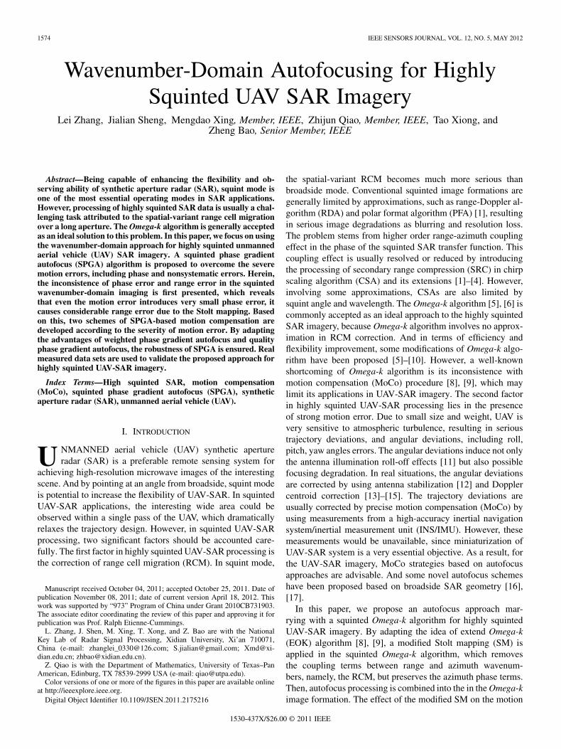
ZHANG et al.: WAVENUMBER-DOMAIN AUTOFOCUSING FOR HIGHLY SQUINTED UAV SAR IMAGERY 1575
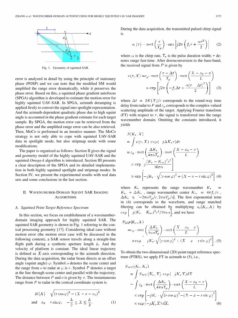
Fig. 1. Geometry of squinted SAR.
error is analyzed in detail by using the principle of stationaryphase (POSP) and we can note that the modified SM wouldamplified the range error dramatically, while it preserves thephase error. Based on this, a squinted phase gradient autofocus(SPGA) algorithm is developed to estimate the motion error forhighly squinted UAV-SAR. In SPGA, azimuth deramping isapplied firstly to convert the signal into spotlight representation.And the azimuth-dependent quadratic phase due to high squintangle is accounted in the phase gradient estimate for each targetsample. By SPGA, the motion error can be retrieved from thephase error and the amplified range error can be also retrieved.Then, MoCo is performed in an iterative manner. The MoCostrategy is not only able to cope with squinted UAV-SARdata in spotlight mode, but also stripmap mode with somemodifications.
The paper is organized as follows: Section II gives the signaland geometry model of the highly squinted UAV-SAR and thesquinted Omega-k algorithm is introduced. Section III presentsa clear description of the SPGA and its detailed implementa-tion in both highly squinted spotlight and stripmap modes. InSection IV, we present the experimental results with real datasets and some conclusions in the last section.
II. WAVENUMUBER-DOMAIN SQUINT SAR IMAGING
ALGORITHMS
A. Squinted Point Target Reference Spectrum
In this section, we focus on establishment of a wavenumber-domain imaging approach for highly squinted SAR. Thesquinted SAR geometry is shown in Fig. 1 referring to the con-ical processing geometry [17]. Considering ideal case withoutmotion error (the motion error case will be discussed in thefollowing content), a SAR sensor travels along a straight-lineflight path during a synthetic aperture length . And thevelocity of platform is constant. The ideal linear trajectoryis defined as -axis corresponding to the azimuth direction.During the data acquisition, the radar beam directs at an offsetangle (squint angle) . Symbol denotes the scene center andthe range from to radar at is . Symbol denotes a targetat the line through scene center and parallel with the trajectory.The distance between and is given by . The instantaneousrange from to radar in the conical coordinate system is
and (1)
During the data acquisition, the transmitted pulsed chirp signalis
(2)
where is the chirp rate, is the pulse duration width; de-notes range fast-time. After downconversion to the base-band,the received signal from is given by
(3)
where corresponds to the round-way timedelay from radar to and corresponds to the complex-valuedscattering amplitude of the target. Applying Fourier transform(FT) with respect to , the signal is transferred into the rangewavenumber domain. Omitting the constants introduced, ityields
(4)
where represents the range wavenumber, range wavenumber center ,
. The first exponential termin (4) corresponds to the waveform, and range matchedfiltering can be obtained by multiplying by
, and we have
(5)
To obtain the two-dimensional (2D) point target reference spec-trum (PTRS), we apply FT in azimuth to (5), i.e.,
(6)
1576 IEEE SENSORS JOURNAL, VOL. 12, NO. 5, MAY 2012
To deduce the analytic expression of PTRS, POSP [19] is readyto be used. Equating the first derivative of the phase functionwith respect to in (6) to zero gives
(7)
Solving the above equation, the stationary point yields
(8)
Then, we substitute for in the phase function of (6). Omit-ting the constants, the PTRS is given by
(9)
where denotes the azimuth wavenumber width andis the azimuth wavenumber center (corresponds to the Dopplercenter). It should be emphasized that the same PTRS expressioncan be also deduced by the equivalent wavelength concept [19].From the exponential term in (9), the relevant portion of the 2Dwavenumber domain phase is
(10)It consists of three terms. The last term in (10) is the linear phasecorresponding to the azimuth position of the target. And thesecond term is the linear phase caused by squinted data acqui-sition introducing a relative offset in azimuth. While in the firstterm, the range and azimuth wavenumbers are coupled yieldingthe RCM. The first term is a function of the target’s slant rangerepresenting the spatial variance of RCM. The PTRS in (10)corresponds to the pulsed chirp waveforms. However, when weconsider frequency modulated continuous waveforms (FMCW),the two-dimension wavenumber expression should be different.For details about the PTRS of FMCW SAR, some novel works[20]–[22] can be consulted.
B. Omega-k and Extended Omega-k Algorithms
Clearly, the PTRS of non-squinted SAR is a special case of(9). With substituting into (10), we have the phase ex-pression of non-squinted SAR.
(11)
In the original Omega-k processing in [5], a change of variablesis applied that
(12)
It is called Stolt mapping, and usually implemented by in-terpolation. SM removes the range and azimuth wavenumbercoupling in the phase, and thus RCM is corrected ideally.
Moreover, high order phase terms corresponding to the azimuthwavenumber are also eliminated precisely. After SM, 2Dinverse Fourier transform (IFT) is followed to focus the 2DSAR image. Although the Omega-k algorithm is accepted asideal and high-accuracy approach for focusing SAR data, itis sensitive to motion error. Therefore, Omega-k algorithm isusually not applied to airborne SAR imagery, where serioustrajectory deviations exist. To overcome the shortness of thestandard Omega-k algorithm in airborne SAR applications,the novel extended Omega-k has been proposed in [8], [9].Considering the broadside case, the modified SM in EOK isgiven by
(13)
Then the phase function through the modified SM is rearrangedinto
(14)
The first exponential term in (14) is a linear term correspondingto the range position of target. Clearly, the modified SM re-solves the range and azimuth wavenumber coupling, namely,corrects the RCM. And the second term depends only on the az-imuth wavenumber and , but no longer couples with the rangewavenumber. Together with the last azimuth linear phase, thesecond term corresponds to the final azimuth focusing. SinceRCM is eliminated, followed range IFT processing can discrim-inate targets at different range into different range cells. And az-imuth IFT is applied to transfer the signal into slow time domain,where the extension of the target response in slow time corre-sponds exactly to its extension in the raw data. Therefore, pre-cise MoCo can be applied at this step, if accurate motion errorinformation is available. After MoCo in this step, range-depen-dent matched filtering is used to compensate the second termin (14) and achieve a well-focused image. In contrast to thestandard Omega-k algorithm, EOK separates the RCM and az-imuth focusing into two independent steps, and thus preciseMoCo can be performed on the slow-time signal after RCMcorrection. Due to the coarse MoCo via navigation measure-ments before performing EOK, and the residual motion errorusually represents phase error only and the range error is usu-ally constrained within one range cell. This assumption is gen-erally valid in broadside SAR, since correction of RCM causedby motion error is corresponding to range cell in the scale ofmeters or decimeters, while the compensation of phase erroris corresponding to the wavelength in the scale of centimetersor decimeters. In this sense, the coarse MoCo is usually accu-rate enough to remove the range error and only the phase errorshould be accounted in the MoCo after RCM correction. In thenext section, we will see that this assumption is only valid inthe non-squinted case, rather than in the highly squinted SARimaging.
Based on the squinted PTRS expression in (9), EOK is easilyextended to the squinted SAR mode, and a modified SM is de-signed as
(15)

ZHANG et al.: WAVENUMBER-DOMAIN AUTOFOCUSING FOR HIGHLY SQUINTED UAV SAR IMAGERY 1577
Then, the phase function in (10) becomes
(16)
Similar to the non-squinted mode, the coupling term betweenrange and azimuth wavenumbers is resolved, correcting theRCM effectively. The second term corresponds to the azimuthfocusing term and the last term corresponds to the final azimuthposition of target in the image. Then, by applying range IFTto obtain range compression and azimuth IFT to transfer thesignal back into the slow-time domain. And time-domain MoCoshould be performed in this stage. At last, azimuth matchedfiltering is performed to achieve high resolution image. Itseems that application of the squinted Omega-k for focusinghighly squinted SAR data is straightforward. However, directapplication of the squinted Omega-k to UAV-SAR imageryencounters inherent difficulties. Due to the lack of precision ofnavigation system, significant motion error is rest after MoCovia the recorded motion measurements. Therefore, data-drivenautofocus approaches are usually necessary to compensate theresidual motion error. This processing is deemed to be con-sistent with the squinted Omega-k algorithm. In the followingsection, an autofocus approach is developed for highly squintedUAV-SAR based on the motion error analysis.
III. MOTION ERROR ANALYSIS AND SQUINTED PHASE
GRADIENT AUTOFOCUS
A. Effects of the Modified SM on Motion Errors
In this section, we introduce the residual motion error intothe signal model and analyze the effect of the modified SM in(15) on it. Considering the residual motion error after coarsecompensation by using the INS/IMU measurements, the slantrange expression in (1) is shifted into
(17)
where denotes the residual motion error. For gen-erality, the residual range error is extended into a polynomialfunction as
(18)
where denotes the -th order coefficient, which is generallydependent on the range and azimuth position of the target. Notethat, in (18) the first-order term is not accounted. Because thefirst-order term in range error induces additional Doppler shiftand range walk, namely, it equivalently causes the squint anglechange. Therefore, the effect can be compensated by Dopplercentriod estimation [14], [15] corresponding to the squint angleestimation.
For simplicity, only exponential terms of received signal isconsidered in the following deduction. After range matched fil-tering, the received signal expression in (4) is rewritten as
(19)
Then, azimuth FT is applied to achieve the PTRS correspondingto the processing in (6), which gives
(20)
According to the POSP, the first derivative of the phase functionwith respect to in (6) is set to zero as
(21)
Due to the lack of information about the range error, it is im-possible to solve the equation perfectly. Herein, we introducean approximation to obtain the stationary point. Generally, theresidual range error after coarse MoCo is nominal comparedwith the range history . In this sense, the residual phaseerror is nominal compared with the phase history of the PTRS.Therefore, we can use the PTRS phase to determine the sta-tionary point and neglect the effect from the phase error. Gen-erally, the difference between the stationary points in (7) and(20) is very small. This assumption simplifies the derivation ofthe stationary point, and it is usually valid in our MoCo. It willbe presented in next subsection that, in our MoCo scheme, weadapt the overlapping sub-aperture processing. During a shortsub-aperture data, the motion error is usually very small andmanifests low-order characteristics, which ensures high accu-racy of above assumption. Furthermore, the MoCo is imple-mented by an iterative correction procedure, which overcomesmotion error stage by stage. Therefore, even if the motion erroris large in the first iterations, it will be small enough withoutaffecting the stationary point approximation after several itera-tions. Therefore, a rigid solution to (21) is given in (8). Bysubstituting (8) into (19), we obtain the expression of PTRS
(22)

1578 IEEE SENSORS JOURNAL, VOL. 12, NO. 5, MAY 2012
Then, by applying the modified SM and subsitituting (15) into(22), we have
(23)
where
(24)and . From(8), we note that is a function of both and , and thus,after the modified SM, is a function of and . Then,azimuth IFT is applied to transfer signal back into the slow-timedomain, which yields
(25)
In order to obtain the analytic expression of ,we use the POSP and have
(26)Due to the small value of the error term, we neglect its contri-bution in to the stationary point calculation and get
(27)
The approximate stationary phase point is
(28)
By Substituting (28) into (25), we have the spectrum that
(29)
And substituting (28) into (8) leads to
(30)
Extending into first-order Taylor series at, we have
(31)
where
(32)
Detailed deduction about above expression can be found inAppendix A. In (31), the first term represents the phase errorin the slow-time domain, which is only related to ,in other words, the squinted SM does not change variance andcharacteristics of the phase error. This consistency of phaseerror before and after SM is also the base that the MoCo canbe successfully used in the non-squinted SAR mode in [8]. Thesecond term is a linear function of , corresponding to therange error. From (32), one can notice that the range error iscomposed by two terms: the first corresponds toconsistent to the phase error, and the second term is inducedby the modified SM. And with the increase of squint angle, thesecond term becomes pronounced. We call this phenomenonas the inconsistence of phase error and range error from themodified SM. Applying IFT with respect to and omittingthe constants introduced, we achieve the range compressedsignal as
(33)
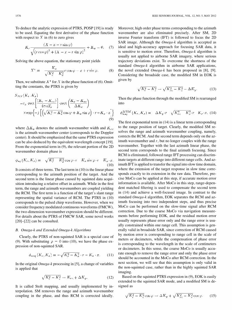
where denotes the range coordinate with respect toand is the bandwidth corresponding to . In this stage,the motion error is expected to be corrected precisely. Inconventional MoCo of airborne SAR applications, the majorityof motion errors are compensated on raw data via navigationmeasurements and the residual motion error is usually nominalcausing no range error. Then, in this stage, the fine MoCo isperformed on the RCM corrected signal [3], [8]. However,in coping with highly squinted SAR data with the modifiedEOK, the RCM error is not only introduced by residual motionerror, but also the modified SM. When and only when ,the range error in (32) equals to . Otherwise, weusually have . For clarity, we seta numerical example to explain the effect of SM on rangeerror. Taking , and changes from
to 1000 meters, the residual range error is assumed asa five-order polynomial function shown in Fig. 2(a), and thecorresponding RCM error is given in Fig. 2(b). In Fig. 2(a), wenote varies within only several centimeters. How-ever, due to the large value of , the correspondingis magnified up to several meters after the modified SM, whichsurely exceeds one resolution cell bringing additional rangecell migration. In other words, even very small range error isrested after coarse MoCo, serious range cell migration presentsafter the SM in highly squinted SAR imagery. In this sense,the requirement of accuracy of MoCo is usually beyond thecapability of INS/IMU systems in conventional airborne SAR,saying nothing of UAV-SAR applications. Therefore, serious
ZHANG et al.: WAVENUMBER-DOMAIN AUTOFOCUSING FOR HIGHLY SQUINTED UAV SAR IMAGERY 1579
Fig. 2. (a) Residual range error. (b) Range error after modified SM.
RCM error and considerable phase error certainly exist in therange compressed signal. For our issue of highly squintedUAV-SAR imagery with the squinted Omega-k algorithm,high precise autofocus approach is necessary to generate highquality image.
B. Squinted Phase Gradient Autofocus (SPGA)
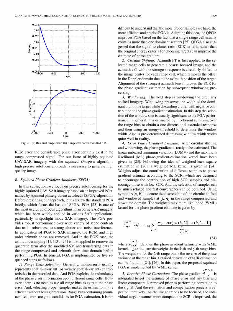
In this subsection, we focus on precise autofocusing for thehighly squinted UAV-SAR imagery based on an improved PGA,named by squinted phase gradient autofocus (SPGA) algorithm.Before presenting our approach, let us review the standard PGAbriefly, which forms the basis of SPGA. PGA [23] is one ofthe most useful autofocus algorithms in airborne SAR imagery,which has been widely applied in various SAR applications,particularly in spotlight mode SAR imagery. The PGA pro-vides robust performance over wide variety of scene contentsdue to its robustness to strong clutter and noise interference.In application of PGA to SAR imagery, the RCM and highorder azimuth phase are removed. And in the EOK case, theazimuth deramping [1], [13], [24] is first applied to remove thequadratic term after the modified SM and transferring data inthe range-compressed and azimuth slow time domain beforeperforming PGA. In general, PGA is implemented by five se-quenced steps as follows.
1) Range Cells Selection: Generally, motion error usuallyrepresents spatial-invariant (or weakly spatial-variant) charac-teristics in the recorded data. And PGA exploits the redundancyof the phase error information upon different range cells. How-ever, there is no need to use all range bins to extract the phaseerror. And, selecting proper samples makes the estimation moreefficient without losing precision. Range bins containing promi-nent scatterers are good candidates for PGA estimation. It is not
difficult to understand that the more proper samples we have, themore efficient and precise PGA is. Adapting this idea, the QPGAimproves PGA based on the fact that a single range cell usuallycontains more than one dominant scatters [25]. QPGA also sug-gested that the signal-to-clutter ratio (SCR) criteria rather thanthe original energy criteria for choosing targets can improve theestimate of phase gradient.
2) Circular Shifting: Azimuth FT is first applied to the se-lected range cells to generate a coarse focused image, and theazimuth cell with the strongest response is circularly shifted tothe image center for each range cell, which removes the offsetin the Doppler domain due to the azimuth position of the target.Alignment of the strongest azimuth bins improves the SCR forthe phase gradient estimation by subsequent windowing pro-cessing.
3) Windowing: The next step is windowing the circularlyshifted imagery. Windowing preserves the width of the domi-nant blur of the target while discarding clutter with negative con-tribution to the phase gradient estimation. In this step the selec-tion of the window size is usually significant to the PGA perfor-mance. In general, it is estimated by incoherent summing overthe range bins to obtain a one-dimensional extended responseand then using an energy-threshold to determine the windowwidth. Also, a pre-determined decreasing window width worksquite well in reality.
4) Error Phase Gradient Estimate: After circular shiftingand windowing, the phase gradient is ready to be estimated. Thelinear unbiased minimum variation (LUMV) and the maximumlikelihood (ML) phase-gradient-estimation kernel have beengiven in [23]. Following the idea of weighted-least squareestimation in [26], a weighted ML kernel is given in [24].Weights adjust the contribution of different samples to phasegradient estimate according to the SCR, which are designedto encourage the contribution of high SCR samples and dis-courage those with low SCR. And the selection of samples canbe much relaxed and fast convergence can be obtained. Usingsymbol to denote the discrete bin of the circular shiftedand windowed samples at in the range compressed andslow time domain. The weighted maximum likelihood (WML)kernel for the phase gradient estimate is given by
(34)
where denotes the phase gradient estimate with WMLkernel. and are the weights in the -th and -th range bins.The weight for the -th range bin is the inverse of the phasevariance of the range bin. Detailed derivation of SCR estimationcan be found in [24], [26]. In this paper, the proposed squintedPGA is implemented by WML kernel.
5) Iterative Phase Correction: The phase gradient isintegrated to get the estimate of phase error and any bias andlinear component is removed prior to performing correction tothe signal. And the estimation and compensation process is re-peated iteratively. As the image trends to be focused, the indi-vidual target becomes more compact, the SCR is improved, the

1580 IEEE SENSORS JOURNAL, VOL. 12, NO. 5, MAY 2012
circular shifting and windowing are more precise and narrow,and the convergence is achieved.
SPGA also follows the five-step processing and retrievesthe phase error iteratively. At first, we select all range cellsof the range compressed signal above a pre-determined SCRthreshold. Then each range cell is deramped to remove thequadratic phase. The reference phase function of the range cellcorresponding to is given by
(35)
where corresponds tothe range history of the center at equivalent range line corre-sponding to . After deramping, we obtain
(36)
where
(37a)
(38b)
According to the derivation in Appendix B, we have the approx-imate expression of the deramped signal as
(39)
where
(40a)
(40b)
(40c)
and correspond to the constant phase termand the linear phase terms, respectively. And is the co-efficient related to the residual quadratic phase after deramping.In the case of non-squinted SAR case, the quadratic coefficientequals to zero and . Regardless of the ap-proximation of (39), the only high order phase terms are cor-responding to the motion error , and thus PGA canbe directly utilized to extract the phase function induced by mo-tion error. However, it is not the case when squint angle is notequal to zero as anymore. And with the increaseof squint angle, the quadratic phase term becomes significant todegrade the estimate of motion error. In this sense, the quadratic
phase term corresponding to should be compensatedbefore implementing PGA to estimate the motion phase error.Fortunately, is a linear function of the target azimuthcoordinate and the residual quadratic phase is azimuth-depen-dent, and thus we can determine the residual quadratic phase byusing the azimuth position of the target. Clearly, in the circularshifting step of the standard PGA, azimuth FT is applied to therange cell in (39) yielding a coarse focused image, and the ma-jority of energy of the target is constrained around the azimuthwavenumber bin corresponding to
(41)
From , we can retrieve the azimuth position of the target.Substituting (40b) and (40c) into (41), we have a quadratic equa-tion of , which gives
(42)
By solving the equation in (42), we obtain the estimation of theazimuth position of the target as follows.
(43)
Therefore, the residual quadratic phase correction can be imple-mented by multiplying the phase function in (44) and derampedsignal in (39) in slow time domain.
(44)
In the circular shifting step of each SPGA iteration, aboveresidual quadratic phase correction is performed for eachsample scatterer.
In highly squinted SAR mode, the deramping can not re-move all quadratic phase of phase function of a target. And theresidual quadratic phase will be treated as phase error in PGAestimate. SPGA, as an extension of PGA, considers the residualquadratic phase ensuring the precise estimate of phase error. Theestimation and compensation of the residual quadratic phaseis embedded into the conventional PGA procedure. Therefore,high quality phase gradient estimate is ensured by the WMLkernel. However, another notable difficulty of phase error re-trieve in the squinted SAR imagery via the squinted Omega-kalgorithm, is the residual range error after the modified SMwe discussed in last subsection. We note that even very smallrange error brings considerable range error after the modifiedSM processing, which surely reduces the precision of phaseerror estimation through PGA. However, we can perform PGAto the deramped data with a lower resolution by the under-sam-pling process. The under-sampling process [27] eliminates theresidual RCM directly by summing up neighboring rangecells into one single cell and is defined as the under-sam-pling ratio. Also under-sampling process can be implementedby extracting only part of frequency band data to obtain a range-compressed data block, which inherently has an energy loss ofthe signal. Therefore, summing scheme should be proper to re-duce the RCM effect on the SPGA.

ZHANG et al.: WAVENUMBER-DOMAIN AUTOFOCUSING FOR HIGHLY SQUINTED UAV SAR IMAGERY 1581
(a) (b)
Fig. 3. (a) Flowchart of the SPGA for medium motion error. (b) Flowchart of the SPGA for severe motion error
As one notes in (33), the residual phase error are directly re-lated to , and therefore we can have the estimate ofresidual motion error by
(45)
where is the integrated phase error from WPGA es-timate. With the estimate of range error, we can perform thefine MoCo in the raw data, and the modified SM follows. Dueto correction of , the residual errors would be less-ening. An iteration procedure can be utilized to correct the en-tire range error effectively. This kind of iteration can be alsofound in [16], [24]. However, it is usually with low efficiencybecause the time-consuming SM interpolation is performed ineach iteration. Actually, in (32) we can find that the relation be-tween the amplified RCM and range error is certain, and directestimate of RCM from the is possible. Then, cor-rection of both phase and RCM errors can be performed to themapped data rather than raw data, which can improve the effi-ciency dramatically. In terms for calculating RCM error after themodified SM, sequentially, is fitted into low-orderpolynomial function and we obtain the estimates of coefficients
as , , and so on. Then, the RCM error after modified SMis estimated by
(46)
Due to clutter and RCM errors, the estimated range error isdeemed to be contaminated by noise in some degree, whichtakes the risk of inaccuracy in polynomial function fitting, espe-cially the high order coefficients and consequently causes unac-ceptable error in RCM calculation. For robust correction, we usea stage-wise scheme by decreasing the number in under-sam-pling iteratively. In the first several iterations, due to severerange error, with large value (eight for instance), is utilized.And low order polynomial fitting, such as three or four orders,is used to get a coarse estimation of motion error. Then bothphase and range error are reduced to a small degree before westart the next iteration, and therefore in this iteration, we canchoose a smaller and higher order polynomial fitting to getfine estimation of both phase and range error. Generally, preciseestimation can be achieved within only several iterations. Forclarity, the flowchart of the SPGA is shown in Fig. 3(a). How-ever, in presence of severe motion error even after coarse MoCo

1582 IEEE SENSORS JOURNAL, VOL. 12, NO. 5, MAY 2012
by using navigation data, the phase error estimate degrades dueto very severe range error occurs after the modified SM. Asa result, the range error calculation via (46) loses its accuracydramatically, which will not ensure accurate correction. In thiscase, we should perform the MoCo on the raw data rather thanon that after the modified SM. By removal of phase and rangeerrors in the raw data, then the residual error is decreased to alow level. Then the Omega-k algorithm is applied, and nominalrange and phase errors are presented in the mapped data. Thenwe perform the SPGA subsequently giving an optimal compen-sation. This scheme is certainly of high computational load, be-cause we have to perform the SM interpolation more than once.But it enables the SPGA cope with very severe motion errorin real highly squinted UAV-SAR imagery. And hybrid of thecorrections before and after SM is direct: correction on the rawdata in the first several iterations, and then correction on dataafter SM in the last iterations, which can make a tradeoff be-tween the precision and computational complexity. The proce-dure of SPGA in dealing with severe motion error is shown inFig. 3(b). In summary, SPGA outperforms the standard PGAin focusing squinted SAR data from two aspects: 1) SPGA con-siders the residual quadratic phase terms after deramping opera-tion, which avoids severe error in the phase gradient estimation;2) The non-systematic RCM induced by both motion error andthe SM processing is overcome in SPGA.
The SPGA is ready to autofocus the highly squinted spot-light SAR image. However, its extension to squinted stripmapUAV-SAR imagery requires some necessary modifications.In general, PGA frameworks cannot be directly applied tostripmap SAR imagery and SPGA is not an exception. How-ever, for the UAV-SAR application, stripmap mode should beone of the most essential operating modes. In the stripmapmode the aperture positions of different sactterers displacewith each other within the whole coherent processing interval.Applying the PGA approaches to the stripmap mode bringsan inherent problem stemming from overlapping aperturesof different scatterers, which span different segments of thephase gradient estimate with potentially different local linearcomponents, will not always give the same phase gradientin the overlapped region [28]. And thus difference of locallinear components from different targets inherently introducesincoherence between phase gradient estimation leading to thefailure of PGA approaches. To overcome this problem in uti-lization of PGA schemes in the stripmap SAR imagery, a simplebut useful scheme is proposed in [29], which shifts signal of thestripmap SAR into spotlight representation by splitting it intosmall azimuth blocks and estimating the error phase gradientfor each segment independently. Then the segmental phasegradients are integrated into segmental phase error functions,and coherent connection is performed to combine them intothe full aperture function. In our SPGA with the sub-apertureprocess, overlapping is applied to extract the information aboutdiscontinuities between two joint sub-aperture phase errorsegments. The overlapping segments also provide overlappingphase error estimates of azimuth blocks, which are illustratedin Fig. 4. The linear phase differences can be easily extractedfrom the overlapping sub-aperture phase functions. In realapplication, the overlapping part can be selected as a quarteror half of a sub-aperture. And the global linear phase term
Fig. 4. Full aperture phase error combination.
is removed from the full-aperture phase error function. Andthen, range error is retrieved from the phase error function.And phase error and range error are estimated and correctediteratively until an optimal convergence.
Another difficulty encountered in the stripmap UAV-SARautofocus is the spatial-variance of motion error. In stripmapmode, radar beam usually covers a much wider scene thanthe spotlight SAR does, especially in the low attitude anglecase. The SPGA assumes the radar beam is narrow enoughthat the motion error represents spatial-invariance. However, inUAV-SAR operating at stripmap mode, this assumption maybe not rigid enough. When accounting the range-dependenceof phase error, range blocking is utilized to ensure applicationof the SPGA. And the range blocks should be small enoughthat the spatial variance of phase error within can be regardedas non-spatial variant case. Contrasting to range blockingprocess, the phase-weighted-estimation PGA (PWE-PGA)[23] provides an estimation kernel for computing the phasegradients with a range-variant model. Since its model is basedon non-squinted SAR geometry, PWE-PGA can’t be directlyextended into SPGA. In our case of phase and range errorcorrection with SPGA, we use the range blocking in estimationand the compensation is independently applied for each block.Consequently, well-focused image of high squinted SAR canbe obtained by the azimuth matched-filtering in the EOKprocessing for each block. And range block images are fused toachieve the full-scene SAR image. A useful procedure of SPGAin deal with highly squinted stripmap UAV SAR imagery isgiven in Fig. 5. And the extension of the MoCo procedure todeal with severe motion error is presented in Fig. 3(b).
IV. REAL DATA EXPERIMENTS
In the following, we give the experimental results of UAVSAR imagery via the presented squinted Omega-k algorithm andSPGA-based MoCo. To illustrate the performance of the pro-posed method, two experiments are carried out by using datasets measured by an experimental SAR system. The first exper-iment is performed to validate the performance of the proposedautofocus scheme in highly squinted UAV-SAR imagery withmedium motion error. And the second experiment is carried outto illustrate its performance under severe motion error. Both ofthe data sets are recorded in one plane sortie. The SAR works at
ZHANG et al.: WAVENUMBER-DOMAIN AUTOFOCUSING FOR HIGHLY SQUINTED UAV SAR IMAGERY 1583
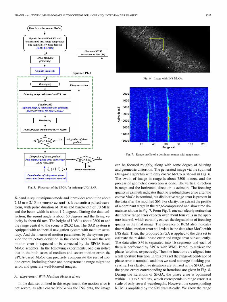
Fig. 5. Flowchart of the SPGA for stripmap UAV-SAR.
X-band in squint stripmap mode and it provides resolution about2.15 m 2.15 m ( ). It transmits a pulsed wave-form, with pulse duration of 10 us and bandwidth of 70 MHz,and the beam width is about 1.2 degrees. During the data col-lection, the squint angle is about 50 degrees and the flying ve-locity is about 60 m/s. The height of UAV is about 2800 m andthe range central to the scene is 28.32 km. The SAR system isequipped with an inertial navigation system with medium accu-racy. And the measured motion parameters by the system pro-vide the trajectory deviation in the coarse MoCo and the restmotion error is expected to be corrected by the SPGA-basedMoCo schemes. In the following experiments, one can noticethat in the both cases of medium and severe motion error, theSPGA-based MoCo can precisely compensate the rest of mo-tion errors, including phase and nonsystematic range migrationerror, and generate well-focused images.
A. Experiment With Medium Motion Error
In the data set utilized in this experiment, the motion error isnot severe, as after coarse MoCo via the INS data, the image
Fig. 6. Image with INS MoCo.
Fig. 7. Range profile of a dominant scatter with range error.
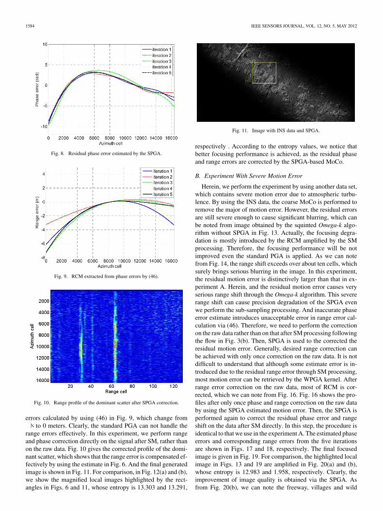
can be focused roughly, along with some degree of blurringand geometric distortion. The generated image via the squintedOmega-k algorithm with only coarse MoCo is shown in Fig. 6.The swath of image in range is about 7500 meters, and theprocess of geometric correction is done. The vertical directionis range and the horizontal direction is azimuth. The focusingquality in azimuth indicates that the residual phase error after thecoarse MoCo is nominal, but distinctive range error is present inthe data after the modified SM. For clarity, we extract the profileof a dominant target in the range-compressed and slow time do-main, as shown in Fig. 7. From Fig. 7, one can clearly notice thatdistinctive range error exceeds over about four cells in the aper-ture interval, which certainly causes the degradation of focusingquality in the final image. The presence of RCM also indicatesthat residual motion error still exists in the data after MoCo withINS data. Then, the proposed SPGA is applied to the data set toestimate the residual phase error and range error subsequently.The data after SM is separated into 16 segments and each ofthem is performed by SPGA with WML kernel to retrieve thephase function, respectively. Then the functions are aligned intoa full aperture function. In this data set the range-dependence ofphase error is nominal, and thus we need no range blocking pro-cessing. For clarity, five iterations are utilized in the SPGA, andthe phase errors corresponding to iterations are given in Fig. 8.During the iterations of SPGA, the phase error is optimizedwithin to 5 radians, which corresponds to range error at ascale of only several wavelengths. However, the correspondingRCM is amplified by the SM dramatically. We show the range
1584 IEEE SENSORS JOURNAL, VOL. 12, NO. 5, MAY 2012
Fig. 8. Residual phase error estimated by the SPGA.
Fig. 9. RCM extracted from phase errors by (46).
Fig. 10. Range profile of the dominant scatter after SPGA correction.
errors calculated by using (46) in Fig. 9, which change fromto 0 meters. Clearly, the standard PGA can not handle the
range errors effectively. In this experiment, we perform rangeand phase correction directly on the signal after SM, rather thanon the raw data. Fig. 10 gives the corrected profile of the domi-nant scatter, which shows that the range error is compensated ef-fectively by using the estimate in Fig. 6. And the final generatedimage is shown in Fig. 11. For comparison, in Fig. 12(a) and (b),we show the magnified local images highlighted by the rect-angles in Figs. 6 and 11, whose entropy is 13.303 and 13.291,
Fig. 11. Image with INS data and SPGA.
respectively . According to the entropy values, we notice thatbetter focusing performance is achieved, as the residual phaseand range errors are corrected by the SPGA-based MoCo.
B. Experiment With Severe Motion Error
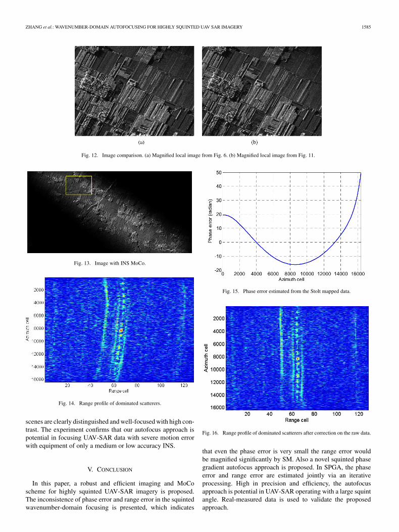
Herein, we perform the experiment by using another data set,which contains severe motion error due to atmospheric turbu-lence. By using the INS data, the coarse MoCo is performed toremove the major of motion error. However, the residual errorsare still severe enough to cause significant blurring, which canbe noted from image obtained by the squinted Omega-k algo-rithm without SPGA in Fig. 13. Actually, the focusing degra-dation is mostly introduced by the RCM amplified by the SMprocessing. Therefore, the focusing performance will be notimproved even the standard PGA is applied. As we can notefrom Fig. 14, the range shift exceeds over about ten cells, whichsurely brings serious blurring in the image. In this experiment,the residual motion error is distinctively larger than that in ex-periment A. Herein, and the residual motion error causes veryserious range shift through the Omega-k algorithm. This severerange shift can cause precision degradation of the SPGA evenwe perform the sub-sampling processing. And inaccurate phaseerror estimate introduces unacceptable error in range error cal-culation via (46). Therefore, we need to perform the correctionon the raw data rather than on that after SM processing followingthe flow in Fig. 3(b). Then, SPGA is used to the corrected theresidual motion error. Generally, desired range correction canbe achieved with only once correction on the raw data. It is notdifficult to understand that although some estimate error is in-troduced due to the residual range error through SM processing,most motion error can be retrieved by the WPGA kernel. Afterrange error correction on the raw data, most of RCM is cor-rected, which we can note from Fig. 16. Fig. 16 shows the pro-files after only once phase and range correction on the raw databy using the SPGA estimated motion error. Then, the SPGA isperformed again to correct the residual phase error and rangeshift on the data after SM directly. In this step, the procedure isidentical to that we use in the experiment A. The estimated phaseerrors and corresponding range errors from the five iterationsare shown in Figs. 17 and 18, respectively. The final focusedimage is given in Fig. 19. For comparison, the highlighted localimage in Figs. 13 and 19 are amplified in Fig. 20(a) and (b),whose entropy is 12.983 and 1.958, respectively. Clearly, theimprovement of image quality is obtained via the SPGA. Asfrom Fig. 20(b), we can note the freeway, villages and wild
ZHANG et al.: WAVENUMBER-DOMAIN AUTOFOCUSING FOR HIGHLY SQUINTED UAV SAR IMAGERY 1585
Fig. 12. Image comparison. (a) Magnified local image from Fig. 6. (b) Magnified local image from Fig. 11.
Fig. 13. Image with INS MoCo.
Fig. 14. Range profile of dominated scatterers.
scenes are clearly distinguished and well-focused with high con-trast. The experiment confirms that our autofocus approach ispotential in focusing UAV-SAR data with severe motion errorwith equipment of only a medium or low accuracy INS.
V. CONCLUSION
In this paper, a robust and efficient imaging and MoCoscheme for highly squinted UAV-SAR imagery is proposed.The inconsistence of phase error and range error in the squintedwavenumber-domain focusing is presented, which indicates
Fig. 15. Phase error estimated from the Stolt mapped data.
Fig. 16. Range profile of dominated scatterers after correction on the raw data.
that even the phase error is very small the range error wouldbe magnified significantly by SM. Also a novel squinted phasegradient autofocus approach is proposed. In SPGA, the phaseerror and range error are estimated jointly via an iterativeprocessing. High in precision and efficiency, the autofocusapproach is potential in UAV-SAR operating with a large squintangle. Real-measured data is used to validate the proposedapproach.

1586 IEEE SENSORS JOURNAL, VOL. 12, NO. 5, MAY 2012
Fig. 17. Phase error from SPGA iteration.
Fig. 18. Range errors extracted form phase errors by (46).
Fig. 19. Image with INS and SPGA.
APPENDIX A
In (31), we extend into Taylor series at. And we have
(A1)
And the first order coefficient is given by
(A2)
where
(A3a)
(A3b)
(A3c)
(A3d)
(A3e)
Hence, we have
(A4)
And the analytic expression of is approximatedas
(A5)

ZHANG et al.: WAVENUMBER-DOMAIN AUTOFOCUSING FOR HIGHLY SQUINTED UAV SAR IMAGERY 1587
Fig. 20. Image comparison. (a) Magnified local image from Fig. 13. (b) Magnified local image from Fig. 19.
APPENDIX B
Extending into Taylor series with respect toround origin, we have approximates that
(B1)where the Taylor coefficients are given by
(B2a)
(B2b)
(B2c)
Similarly, we also have
(B3)
where the corresponding coefficients are
(B4a)
(B4b)
Then, the analytic expression of signal after deramping is ap-proximated by
(B5)
where
(B6a)
(B6b)
(B6c)
ACKNOWLEDGMENT
The authors thank the anonymous reviewers for their valuablecomments to improve the paper quality.
REFERENCES
[1] W. G. Carrara, R. S. Goodman, and R. M. Majewski, Spotlight Syn-thetic Aperture Radar: Signal Processing Algorithm [M]. Boston,MA: Artech House, 1995.
[2] R. K. Raney, H. Runge, R. Bamler, I. G. Cumming, and F. H. Wong,“Precision SAR processing using chirp scaling,” IEEE Trans. Geosci.Remote Sens., vol. 32, pp. 786–799, Jul. 1994.
[3] A. Moreira and H. Yonghong, “Airborne SAR processing of highlysquinted data using a chirp scaling approach with integrated motioncompensation,” IEEE Trans. Geosci. Remote Sens., vol. 32, no. 5, pp.1029–1040, Sep. 1994.
[4] G. W. Davidson, I. G. Cumming, and M. R. Ito, “A chirp scaling ap-proach for processing squint mode SAR data,” IEEE Trans. Aerosp.Electron. Syst., vol. 32, no. 1, pp. 121–133, Jan. 1996.
[5] C. Cafforio, C. Prati, and F. Rocca, “SAR data focusing using seismicmigration techniques,” IEEE Trans. Aerosp. Electron. Syst., vol. 27, no.2, pp. 194–207, 1991.
[6] R. Bamler, “A comparison of range-Doppler and wavenumber domainSAR focusing algorithms,” IEEE Trans. Geosci. Remote Sens., vol. 30,no. 4, pp. 706–713, Sep. 1992.
[7] G. Cumming, Y. L. Neo, and F. Hong, “Interpretations of the Omega-kalgorithm and comparisons with other algorithms,” in Proc. IGARSS,Toulouse, France, 2003, pp. 1455–1458.
[8] A. Reigber, E. Alivizatos, A. Potsis, and A. Moreira, “Extendedwavenumber-domain synthetic aperture radar focusing with integratedmotion compensation,” IEE Proc.—Radar Sonar Navig., vol. 153, no.3, pp. 301–310, Jun. 2006.
[9] E. Alivizatos, A. Reigber, and A. Moreira, “SAR processing with mo-tion compensation using the extended wavenumber algorithm,” in Proc.EUSAR, Ulm, Germany, 2004, pp. 157–160.
[10] M. Vandewal et al., “Efficient and precise processing for squinted spot-light SAR through a modified Stolt mapping,” EURASIP J. Adv. SignalProcess., vol. 2007, pp. 1–10.
[11] A. W. Doerry, “Automatic compensation of antenna beam roll-off inSAR images,” Sandia, 2006, Rep. SAND2006-2632.
[12] J. C. Kirk, “Motion compensation for synthetic aperture radar,” IEEETrans. Aerosp. Electron. Syst., vol. AES-11, no. 3, pp. 338–348, May1975.
[13] G. W. Davidson and I. Cumming, “Signal properties of spacebornesquint-mode SAR,” IEEE Trans. Geosci. Remote Sens., vol. 35, no. 3,pp. 611–617, May 1997.
[14] S. N. Madsen, “Estimating the Doppler centriod of SAR data,” IEEETrans Aerosp. Electron. Syst., vol. 25, no. 2, pp. 134–140, Mar. 1989.
[15] F. H. Wang and I. G. Cumming, “A combined SAR Doppler centroidestimation scheme based upon signal phase,” IEEE Trans. Geosci. Re-mote Sens., vol. 34, no. 3, pp. 696–707, May 1996.
[16] M. Xing, X. Jiang, R. Wu, F. Zhou, and Z. Bao, “Motion compensationfor UAV SAR based on raw radar data,” IEEE Trans. Geosci. RemoteSens., vol. 47, no. 8, pp. 2870–2883, Aug. 2009.
[17] J. T. G. Partida, P. A. Gonzalez, and M. B. Garcia, “SAR System forUAV operation with motion error compensation beyond the resolutioncell,” Sensors, vol. 8, pp. 3384–3405, 2008.
[18] G. Fornaro, E. Sansosti, R. Lanari, and M. Tesauro, “Role of processinggeometry in SAR raw data processing,” IEEE Trans. Aerosp. Electron.Syst., vol. 38, no. 2, pp. 441–454, Apr. 2002.

1588 IEEE SENSORS JOURNAL, VOL. 12, NO. 5, MAY 2012
[19] I. G. Cumming and F. H. Wong, Digital Processing of Synthetic Aper-ture Radar Data: Algorithms and Implementation. Norwood, MA:Artech House, 2005.
[20] Meta, P. Hoogeboom, and L. P. Ligthart, “Signal processing forFMCW SAR,” IEEE Trans. Geosci. Remote Sens., vol. 45, no. 11, pp.3519–3532, Nov. 2007.
[21] Z. Jiang, K. Huang-Fu, and J. Wan, “A chirp transform algorithm forprocessing squint mode FMCW SAR data,” IEEE Geosci. RemoteSens. Lett., vol. 4, no. 3, pp. 377–381, Jul. 2007.
[22] R. Wang, O. Loffeld, H. Nies, S. Knedlik, M. Hägelen, and H. Essen,“Focus FMCW SAR data using the wavenumber domain algorithm,”IEEE Trans. Geosci. Remote Sens., vol. 48, no. 4, pp. 2109–2118, Apr.2007.
[23] D. E. Wahl, P. H. Eichel, D. C. Ghiglia, and C. V. Jakowatz Jr., “Phasegradient autofocus—A robust tool for high resolution phase correc-tion,” IEEE Trans. Aerosp. Electron. Syst., vol. 30, no. 3, pp. 827–835,Jul. 1994.
[24] K. A. C. de Macedo, R. Scheiber, and A. Moreira, “An autofocus ap-proach for residual motion errors with application to airborne repeated-pass SAR interferometry,” IEEE Trans. Geosci. Remote Sens., vol. 46,no. 10, pp. 3151–3162, Oct. 2008.
[25] H. L. Chan and T. S. Yeo, “Noniterative quality phase-gradient aut-ofocus (QPGA) algrotihm for spotlight SAR imagery,” IEEE Trans.Geosci. Remote Sens., vol. 36, no. 5, pp. 1531–1539, Sep. 1998.
[26] W. Ye, T. S. Yeo, and Z. Bao, “Weighted least-squares estimation ofphase errors for SAR/ISAR autofocus,” IEEE Trans. Geosci. RemoteSens., vol. 37, no. 5, pp. 2487–2494, Sep. 1999.
[27] A. W. Doerry, “Autofocus correction of excessive migration in syn-thetic aperture radar images,” Sandia, 2004, Rep. SAND2004-4770.
[28] D. E. Wahl, C. V. Jakowatz Jr., P. A. Thompson, and D. C. Ghiglia,“New approach to strip-map SAR autofocus,” in Proc. 6th IEEE DigitalSignal Process. Workshop, Oct. 1994, pp. 53–56.
[29] D. G. Thompson, J. S. Bates, D. V. Arnold, and D. G. Long, “Extendingthe phase gradient autofocus algorithm for low-altitude stripmap modeSAR,” in Proc IGARSS, Jul. 1999, pp. 564–566.
Lei Zhang was born in Zhejiang Province, China in1984. He received the B.S. degree in mechanism andelectrical engineering from Chang’an University,Xi’an, China, in 2006, and is currently workingtoward Ph.D. degree in signal and informationprocessing at the National Key Lab of Radar SignalProcessing, Xidian University, Xi’an, China.
His major research interests are radar imaging(SAR/ ISAR).
Jialian Sheng was born in Zhejiang Province, China,1987. She received the B.S. degree in biomedical en-gineering from Xidian University, Xi’an, China, in2010, and is currently working toward the Ph.D. de-gree in signal and information processing from theNational Lab for Radar Signal Processing at the sameuniversity.
Her major research interests are radar signal pro-cessing and sparse optimization.
Mengdao Xing (M’04) was born in Zhejiang, China,in November, 1975. He received the B.Eng. and Ph.D.degrees in electrical engineering from Xidian Univer-sity, Xi’an, China in 1997 and 2002, respectively.
He is currently a Full Professor with the NationalKey Laboratory for Radar Signal Processing, XidianUniversity. His research interests include SAR,ISAR, and over the horizon radar (OTHR).
Zhijun Qiao (M’10) received the Ph.D. degree in ap-plied math from the Institute of Mathematics, FudanUniversity, Shanghai, China, in 1997.
From 1999 to 2001, he was a Humboldt ResearchFellow with the Department of Mathematics andComputer Science, University of Kassel, Kassel,Germany. From 2001 to 2004, he was a Researcherwith the Theoretical Division, Los Alamos NationalLaboratory, Kassel, Germany. He has also beena Professor with the Department of Mathematics,Liaoning University, Shenyang City, China, since
1997 and is currently with the Department of Mathematics, The University ofTexas-Pan American, Edinburg, U.K. He is currently the Editor-in-Chief of thePacific Journal of Applied Mathematics. He has published two monographsand more than 90 articles in peer-reviewed international journals. His researchinterest includes nonlinear partial differential equations and its application inradar imaging.
Dr. Qiao’s dissertation was one of the first 100 excellent Ph.D. dissertationsawarded in 1999. He is the PI of two grants under the Department of DefenseProgram and the Norman Hackerman Advanced Research Program.
Tao Xiong was born in Hubei Province, China in1984. He received the B.S. degree in measuringand control technology and instrumentations fromXidian University, Xi’an, China, in 2006, wherehe is currently working toward the Ph.D. degree insignal processing and information from the NationalKey Lab of Radar Signal Processing.
His major research interests are radar imaging(Bistatic SAR/ISAR).
Zheng Bao (M’80–SM’90) was born in Jiangsu,China. He received the B.S. degree from the Com-munication Engineering Institute of China in 1953.
Currently, he is a Professor with Xidian Univer-sity, Xi’an, China, and the chairman of the academicboard of the National Key Lab of Radar Signal Pro-cessing, Xidian University. He has authored or coau-thored six books and published over 300 papers. Now,his research fields include space-time adaptive pro-cessing (STAP), radar imaging (SAR/ISAR), auto-matic target recognition (ATR) and over-the-horizon
radar (OTHR) signal processing.Professor Bao is a member of the Chinese Academy of Sciences.