Embed Size (px)
Citation preview

button of the Animate toolbar. A graphical Storage T-bar graphically depicts the entitiesin a storage facility.
� The Seize button allows the modeler to define a so-called seize area to animate entitiesseizing a resource.
� The Parking button allows the modeler to define a so-called parking area to animateparking areas for transporters.
� The Transporter button allows the modeler to design a visual representation (picture)for a transporter.
� The Station button allows the modeler to specify an icon for a particular Stationmodule.
� The Intersection button allows the modeler to specify an intersection in a network ofautomated guided vehicles (AGVs). These are transporter-type objects that must keeptrack of their positions in the system to avoid collisions. AGVs are not covered inthis book.
� The Route button is used to specify the animation path for moving entities in thesystem.
� The Segment button is used to specify the animation path of a conveyor.� The Distance button is used to specify the animation path of a transporter.� The Network button is used to specify the animation path of an AGV. Unlike ordinarytransporters, Arena endows AGVs with the capability of sensing each other to avoidcollisions.
� The Promote Path button is used to promote a visual line to an animation path of adesired object.
The use of the Animate Transfer toolbar and various transportation-related moduleswill be illustrated in three examples in the sequel.
13.3 EXAMPLE: A BULK-MATERIAL PORT
Bulk materials are an important component of international trade, and their trans-portation is mediated by numerous seaports worldwide. Important bulk materialsinclude iron ore, cement, bauxite, grain, oil, and coal. For analysis of port facilities,see Altiok (1998), White (1984), and Crook (1980).
This example illustrates bulk port operations, using the notions of station, entityrouting among stations, entity pick-up and drop-off by another entity, and the controlof entity movements using logical gating. It concerns a bulk material port, calledPort Tamsar, at which cargo ships arrive and wait to be loaded with coal for their returnjourney. Cargo ship movement in port is governed by tug boats, which need to beassigned as a requisite resource. The port has a single berth where the vessels dock, anda single ship loader that loads the ships. A schematic representation of the layout of PortTamsar is depicted in Figure 13.2.
Port Tamsar operates continually 24 hours a day and 365 days a year. The annualcoal production plan calls for nominal deterministic ship arrivals at the rate of one shipevery 28 hours. However, ships usually do not arrive on time due to weather conditions,rough seas, or other reasons, and consequently, each ship is given a 5-day grace periodcommonly referred to as the lay period (see Jagerman and Altiok [1999]). We assumethat ships arrive uniformly in their lay periods and queue up FIFO (if necessary) at
316 Modeling Transportation Systems

an offshore anchorage location, whence they are towed into port by a single tug boat assoon as the berth becomes available. The tug boat is stationed at a tug station located ata distance of 30 minutes away from the offshore anchorage. Travel between the offshoreanchorage and the berth takes exactly 1 hour. We assume that there is an uninterruptedcoal supply to the ship loader at the coal-loading berth, and that ship loading times areuniformly distributed between 14 and 18 hours. Once a ship is loaded at the berth, thetug boat tows it away to the offshore anchorage, whence the boat departs with itscoal for its destination. Departing vessels are accorded higher priority in seizing thetug boat.
An important environmental factor in many port locations around the world is tidaldynamics. Cargo ships are usually quite large and need deep waters to get into and outof port. Obviously, water depth increases with high tide and decreases with low tide,where the time between two consecutive high tides is precisely 12 hours. We assumethat ships can go in and come out of port only during the middle 4 hours of high tide.Thus, the tidal window at the port is closed for 8 hours and open for 4 hours every12 hours.
We wish to simulate Port Tamsar for 1 year (8760 hours) to estimate berth and shiploader utilization, as well as the expected port time per ship. We mention parentheti-cally that although a number of operating details have been omitted to simplify themodeling problem, the foregoing description is quite realistic and applicable to manybulk material ports and container ports around the world.
An Arena model of Port Tamsar consists of four main segments: ship arrivals,tugboat operations, coal-loading operations at the berth, and tidal window modulation.These will be described next in some detail along with simulation results.
13.3.1 SHIP ARRIVALS
Ship arrivals are implemented in the Arena model segment depicted in Figure 13.3.Ship arrivals are generated deterministically by the Create module, called VesselArrivals, at the rate of one ship every 28 hours. On creation, a ship entity immediatelyproceeds to the Delaymodule, called Lay Period, where it is delayed uniformly between
TugStation
1 Hour
0.5 Hour
Tug Boat
Coal-LoadingBerth
ShipLoader
CoalPile
1 Hour
OffshoreShipAnchorage
Figure 13.2 Layout of Port Tamsar.
Modeling Transportation Systems 317

0 and 120 hours to model an actual arrival within its lay period. The dialog boxes ofmodules Vessel Arrivals and Lay Period are displayed in Figure 13.4.
In due time, the ship entity enters the Assign module, called Mark Arrival Time,where its (actual) arrival time is stored in its ArrTime attribute. The ship entity thenenters the Seize module, called Get Berth, whose dialog box is displayed in Figure 13.5.
Figure 13.4 Dialog boxes of the Create module Vessel Arrivals and the Delay module Lay Period.
Figure 13.3 Arena model segment implementing ship arrivals at Port Tamsar.
318 Modeling Transportation Systems
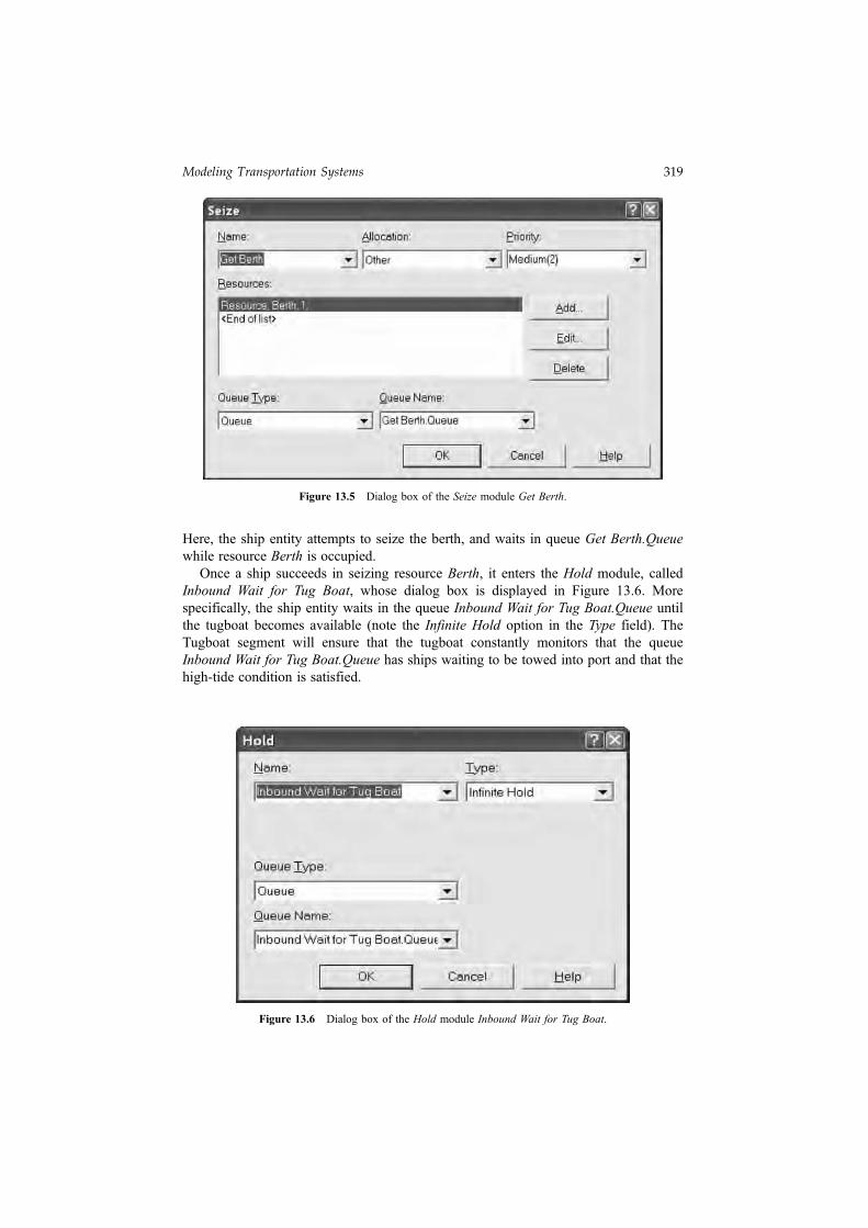
Here, the ship entity attempts to seize the berth, and waits in queue Get Berth.Queuewhile resource Berth is occupied.
Once a ship succeeds in seizing resource Berth, it enters the Hold module, calledInbound Wait for Tug Boat, whose dialog box is displayed in Figure 13.6. Morespecifically, the ship entity waits in the queue Inbound Wait for Tug Boat.Queue untilthe tugboat becomes available (note the Infinite Hold option in the Type field). TheTugboat segment will ensure that the tugboat constantly monitors that the queueInbound Wait for Tug Boat.Queue has ships waiting to be towed into port and that thehigh-tide condition is satisfied.
Figure 13.5 Dialog box of the Seize module Get Berth.
Figure 13.6 Dialog box of the Hold module Inbound Wait for Tug Boat.
Modeling Transportation Systems 319
13.3.2 TUG BOAT OPERATIONS
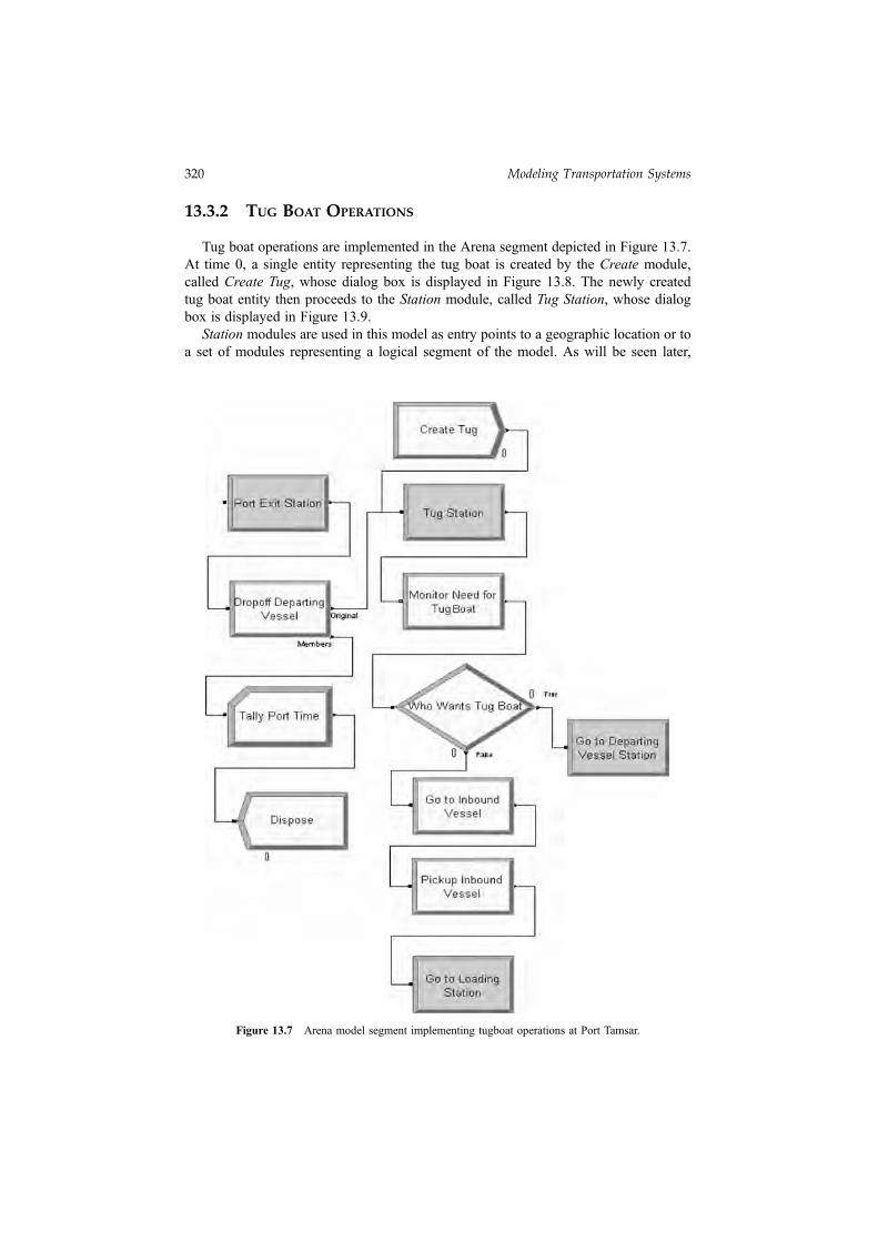
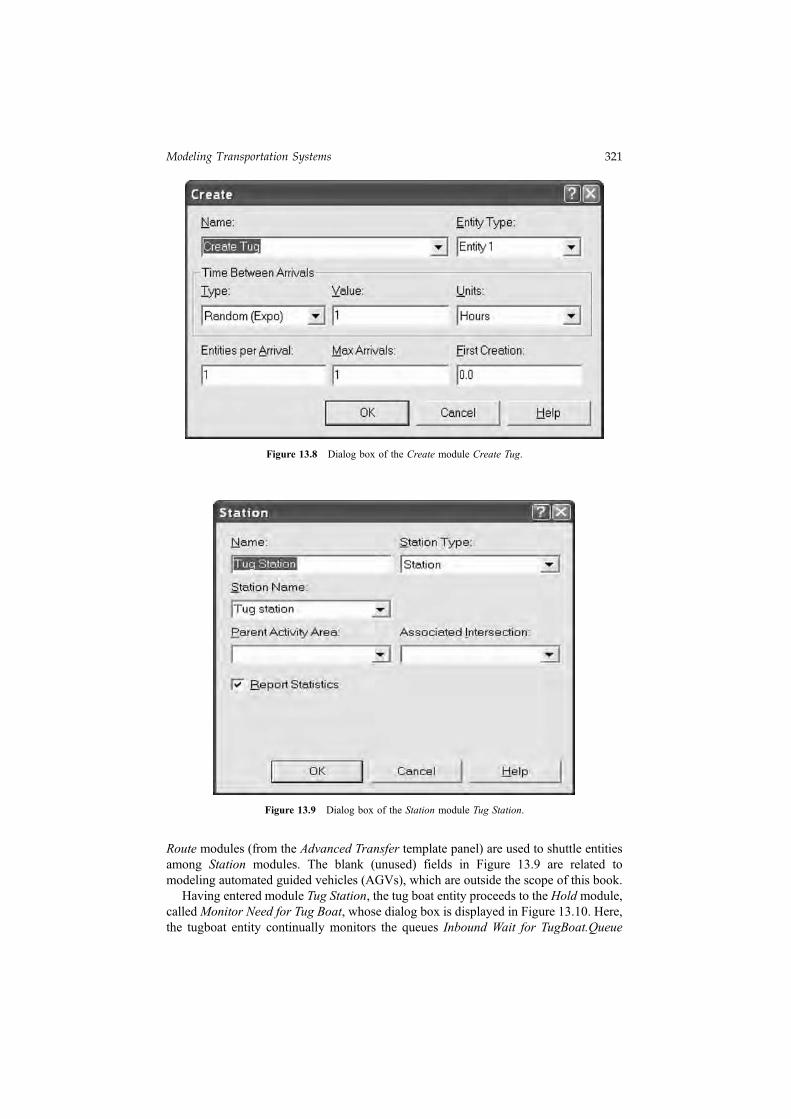
Tug boat operations are implemented in the Arena segment depicted in Figure 13.7.At time 0, a single entity representing the tug boat is created by the Create module,called Create Tug, whose dialog box is displayed in Figure 13.8. The newly createdtug boat entity then proceeds to the Station module, called Tug Station, whose dialogbox is displayed in Figure 13.9.
Station modules are used in this model as entry points to a geographic location or toa set of modules representing a logical segment of the model. As will be seen later,
Figure 13.7 Arena model segment implementing tugboat operations at Port Tamsar.
320 Modeling Transportation Systems
Route modules (from the Advanced Transfer template panel) are used to shuttle entitiesamong Station modules. The blank (unused) fields in Figure 13.9 are related tomodeling automated guided vehicles (AGVs), which are outside the scope of this book.
Having entered module Tug Station, the tug boat entity proceeds to the Hold module,calledMonitor Need for Tug Boat, whose dialog box is displayed in Figure 13.10. Here,the tugboat entity continually monitors the queues Inbound Wait for TugBoat.Queue
Figure 13.8 Dialog box of the Create module Create Tug.
Figure 13.9 Dialog box of the Station module Tug Station.
Modeling Transportation Systems 321
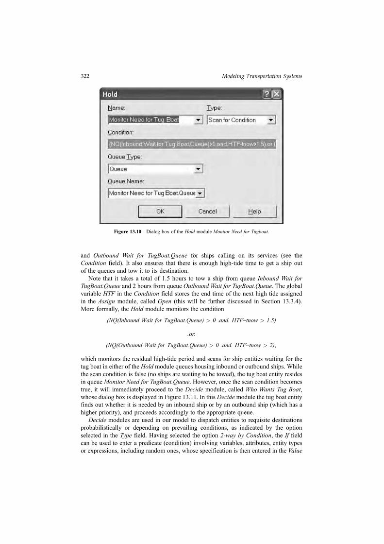
and Outbound Wait for TugBoat.Queue for ships calling on its services (see theCondition field). It also ensures that there is enough high-tide time to get a ship outof the queues and tow it to its destination.
Note that it takes a total of 1.5 hours to tow a ship from queue Inbound Wait forTugBoat.Queue and 2 hours from queue Outbound Wait for TugBoat.Queue. The globalvariable HTF in the Condition field stores the end time of the next high tide assignedin the Assign module, called Open (this will be further discussed in Section 13.3.4).More formally, the Hold module monitors the condition
(NQ(Inbound Wait for TugBoat.Queue) > 0 .and. HTF–tnow > 1.5)
.or.
(NQ(Outbound Wait for TugBoat.Queue) > 0 .and. HTF–tnow > 2),
which monitors the residual high-tide period and scans for ship entities waiting for thetug boat in either of the Hold module queues housing inbound or outbound ships. Whilethe scan condition is false (no ships are waiting to be towed), the tug boat entity residesin queue Monitor Need for TugBoat.Queue. However, once the scan condition becomestrue, it will immediately proceed to the Decide module, called Who Wants Tug Boat,whose dialog box is displayed in Figure 13.11. In this Decide module the tug boat entityfinds out whether it is needed by an inbound ship or by an outbound ship (which has ahigher priority), and proceeds accordingly to the appropriate queue.
Decide modules are used in our model to dispatch entities to requisite destinationsprobabilistically or depending on prevailing conditions, as indicated by the optionselected in the Type field. Having selected the option 2-way by Condition, the If fieldcan be used to enter a predicate (condition) involving variables, attributes, entity typesor expressions, including random ones, whose specification is then entered in the Value
Figure 13.10 Dialog box of the Hold module Monitor Need for Tugboat.
322 Modeling Transportation Systems
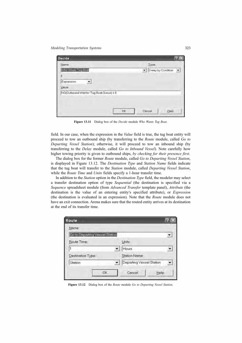
field. In our case, when the expression in the Value field is true, the tug boat entity willproceed to tow an outbound ship (by transferring to the Route module, called Go toDeparting Vessel Station); otherwise, it will proceed to tow an inbound ship (bytransferring to the Delay module, called Go to Inbound Vessel). Note carefully howhigher towing priority is given to outbound ships, by checking for their presence first.
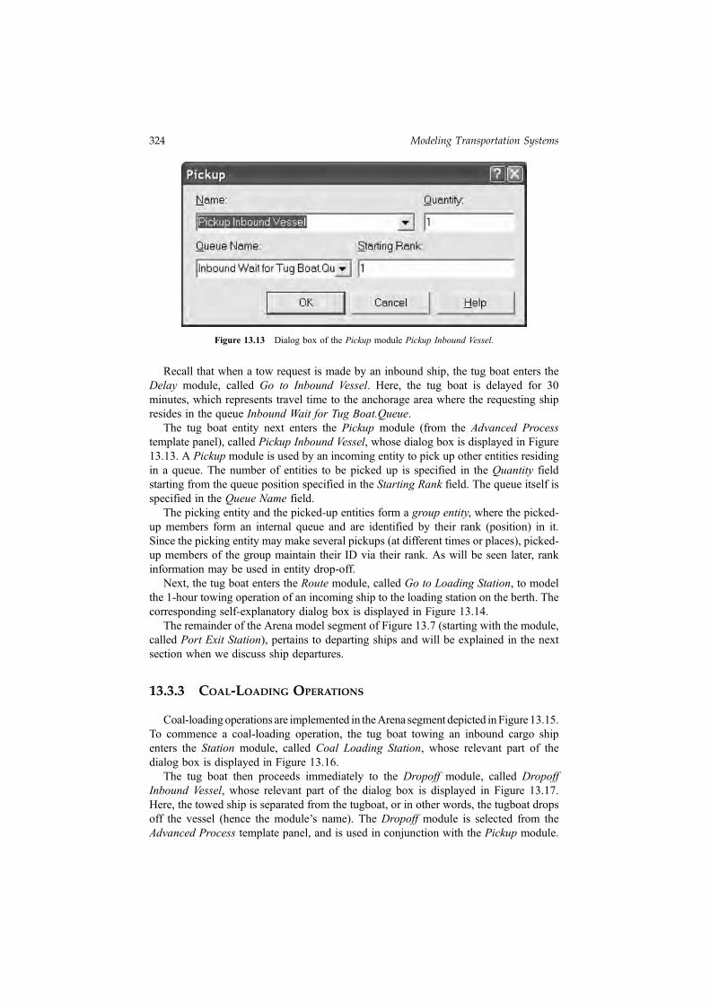
The dialog box for the former Route module, called Go to Departing Vessel Station,is displayed in Figure 13.12. The Destination Type and Station Name fields indicatethat the tug boat will transfer to the Station module, called Departing Vessel Station,while the Route Time and Units fields specify a 1-hour transfer time.
In addition to the Station option in the Destination Type field, the modeler may selecta transfer destination option of type Sequential (the destination is specified via aSequence spreadsheet module (from Advanced Transfer template panel), Attribute (thedestination is the value of an entering entity
,s specified attribute), or Expression
(the destination is evaluated in an expression). Note that the Route module does nothave an exit connection. Arena makes sure that the routed entity arrives at its destinationat the end of its transfer time.
Figure 13.11 Dialog box of the Decide module Who Wants Tug Boat.
Figure 13.12 Dialog box of the Route module Go to Departing Vessel Station.
Modeling Transportation Systems 323
Recall that when a tow request is made by an inbound ship, the tug boat enters theDelay module, called Go to Inbound Vessel. Here, the tug boat is delayed for 30minutes, which represents travel time to the anchorage area where the requesting shipresides in the queue Inbound Wait for Tug Boat.Queue.
The tug boat entity next enters the Pickup module (from the Advanced Processtemplate panel), called Pickup Inbound Vessel, whose dialog box is displayed in Figure13.13. A Pickup module is used by an incoming entity to pick up other entities residingin a queue. The number of entities to be picked up is specified in the Quantity fieldstarting from the queue position specified in the Starting Rank field. The queue itself isspecified in the Queue Name field.
The picking entity and the picked-up entities form a group entity, where the picked-up members form an internal queue and are identified by their rank (position) in it.Since the picking entity may make several pickups (at different times or places), picked-up members of the group maintain their ID via their rank. As will be seen later, rankinformation may be used in entity drop-off.
Next, the tug boat enters the Route module, called Go to Loading Station, to modelthe 1-hour towing operation of an incoming ship to the loading station on the berth. Thecorresponding self-explanatory dialog box is displayed in Figure 13.14.
The remainder of the Arena model segment of Figure 13.7 (starting with the module,called Port Exit Station), pertains to departing ships and will be explained in the nextsection when we discuss ship departures.
13.3.3 COAL-LOADING OPERATIONS
Coal-loadingoperations are implemented in theArena segment depicted inFigure 13.15.To commence a coal-loading operation, the tug boat towing an inbound cargo shipenters the Station module, called Coal Loading Station, whose relevant part of thedialog box is displayed in Figure 13.16.
The tug boat then proceeds immediately to the Dropoff module, called DropoffInbound Vessel, whose relevant part of the dialog box is displayed in Figure 13.17.Here, the towed ship is separated from the tugboat, or in other words, the tugboat dropsoff the vessel (hence the module
,s name). The Dropoff module is selected from the
Advanced Process template panel, and is used in conjunction with the Pickup module.
Figure 13.13 Dialog box of the Pickup module Pickup Inbound Vessel.
324 Modeling Transportation Systems
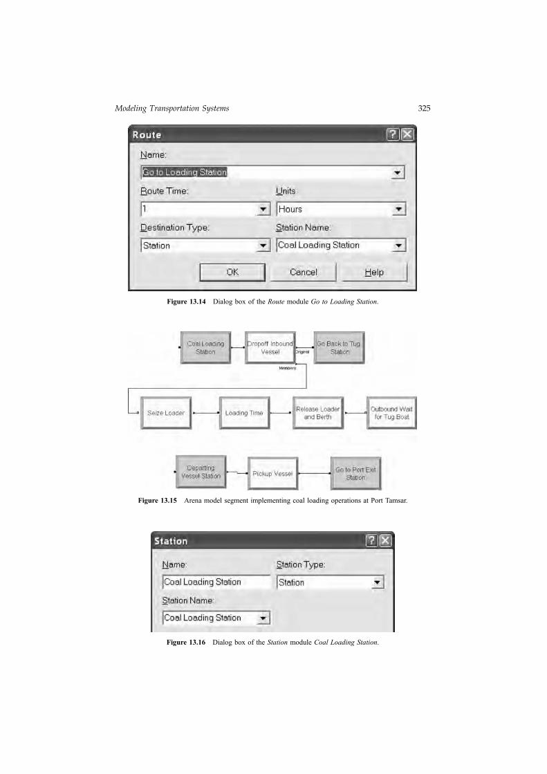
Figure 13.14 Dialog box of the Route module Go to Loading Station.
Figure 13.15 Arena model segment implementing coal loading operations at Port Tamsar.
Figure 13.16 Dialog box of the Station module Coal Loading Station.
Modeling Transportation Systems 325
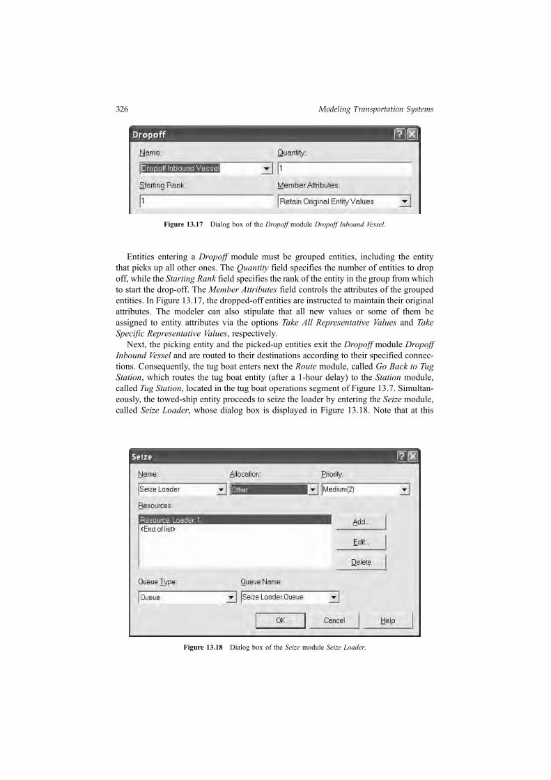
Entities entering a Dropoff module must be grouped entities, including the entitythat picks up all other ones. The Quantity field specifies the number of entities to dropoff, while the Starting Rank field specifies the rank of the entity in the group from whichto start the drop-off. The Member Attributes field controls the attributes of the groupedentities. In Figure 13.17, the dropped-off entities are instructed to maintain their originalattributes. The modeler can also stipulate that all new values or some of them beassigned to entity attributes via the options Take All Representative Values and TakeSpecific Representative Values, respectively.
Next, the picking entity and the picked-up entities exit the Dropoff module DropoffInbound Vessel and are routed to their destinations according to their specified connec-tions. Consequently, the tug boat enters next the Route module, called Go Back to TugStation, which routes the tug boat entity (after a 1-hour delay) to the Station module,called Tug Station, located in the tug boat operations segment of Figure 13.7. Simultan-eously, the towed-ship entity proceeds to seize the loader by entering the Seize module,called Seize Loader, whose dialog box is displayed in Figure 13.18. Note that at this
Figure 13.17 Dialog box of the Dropoff module Dropoff Inbound Vessel.
Figure 13.18 Dialog box of the Seize module Seize Loader.
326 Modeling Transportation Systems

time the loader is always available, since the previous departing ship (if any) must havealready released it. Once the loader is seized, the ship entity proceeds to the Delaymodule, called Loading Time, to model a uniform loading time between 14 and 18 hours.
Following the loading delay, the ship entity releases the loader and berth resourcessimultaneously by entering the Release module, called Release Loader and Berth,whose self-explanatory dialog box is displayed in Figure 13.19.
Finally, the ship entity proceeds to the Hold module, called Outbound Wait for TugBoat, to await its turn to be towed to the anchorage by the tugboat. The dialog boxof this module is analogous to that of the Hold module, called Inbound Wait for TugBoat, in the ship arrivals segment shown in Figure 13.3. As soon as the ship entity isplaced in the queue Outbound Wait for Tug Boat.Queue, the tug boat entity will bedispatched in due time from module Tug Station in the tug boat operations segmentof Figure 13.7 to module Departing Vessel Station in the coal-loading segment ofFigure 13.15. It then enters the Pickup module, called Pickup Vessel, whose dialogbox is displayed in Figure 13.20. The tug boat entity picks up the waiting ship entity
Figure 13.19 Dialog box of the Release module Release Loader and Berth.
Figure 13.20 Dialog box of the Pickup module Pickup Vessel.
Modeling Transportation Systems 327
and proceeds to the port exit by entering the Route module, called Go to Port ExitStation, which routes it 1 hour later to module Port Exit Station in the tug boatoperations segment of Figure 13.7. Note that at this point the tug boat and ship entitiesleft the coal-loading operations segment of Figure 13.15, and entered the tug boatoperations segment of Figure 13.7. The tug boat entity then drops off the ship entitywith its original attributes in the Dropoff module, called Dropoff Departing Vessel, andproceeds immediately to module Tug Station (both in the tug boat operations segmentof Figure 13.7). The trip distance is assumed negligible, and therefore the trip isinstantaneous.
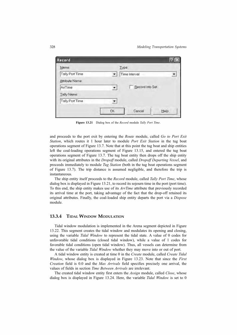
The ship entity itself proceeds to the Record module, called Tally Port Time, whosedialog box is displayed in Figure 13.21, to record its sojourn time in the port (port time).To this end, the ship entity makes use of its ArrTime attribute that previously recordedits arrival time at the port, taking advantage of the fact that the drop-off retained itsoriginal attributes. Finally, the coal-loaded ship entity departs the port via a Disposemodule.
13.3.4 TIDAL WINDOW MODULATION
Tidal window modulation is implemented in the Arena segment depicted in Figure13.22. This segment creates the tidal window and modulates its opening and closing,using the variable Tidal Window to represent the tidal state. A value of 0 codes forunfavorable tidal conditions (closed tidal window), while a value of 1 codes forfavorable tidal conditions (open tidal window). Thus, all vessels can determine fromthe value of the variable Tidal Window whether they may move into or out of port.
A tidal window entity is created at time 0 in the Create module, called Create TidalWindow, whose dialog box is displayed in Figure 13.23. Note that since the FirstCreation field is 0.0 and the Max Arrivals field specifies precisely one arrival, thevalues of fields in section Time Between Arrivals are irrelevant.
The created tidal window entity first enters the Assign module, called Close, whosedialog box is displayed in Figure 13.24. Here, the variable Tidal Window is set to 0
Figure 13.21 Dialog box of the Record module Tally Port Time.
328 Modeling Transportation Systems
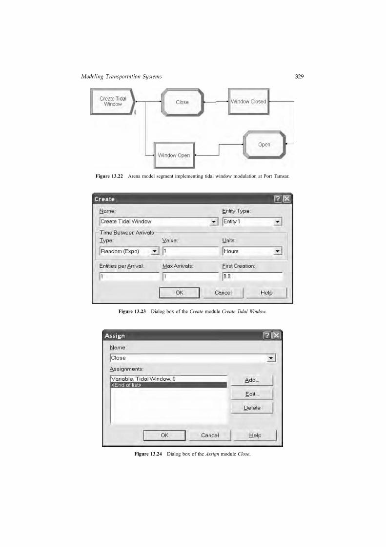
Figure 13.22 Arena model segment implementing tidal window modulation at Port Tamsar.
Figure 13.23 Dialog box of the Create module Create Tidal Window.
Figure 13.24 Dialog box of the Assign module Close.
Modeling Transportation Systems 329
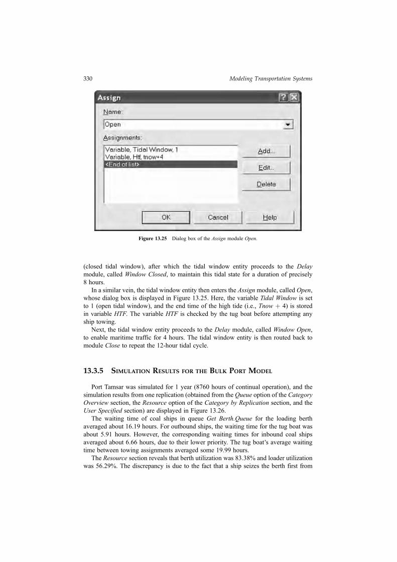
(closed tidal window), after which the tidal window entity proceeds to the Delaymodule, called Window Closed, to maintain this tidal state for a duration of precisely8 hours.
In a similar vein, the tidal window entity then enters the Assign module, called Open,whose dialog box is displayed in Figure 13.25. Here, the variable Tidal Window is setto 1 (open tidal window), and the end time of the high tide (i.e., Tnow þ 4) is storedin variable HTF. The variable HTF is checked by the tug boat before attempting anyship towing.
Next, the tidal window entity proceeds to the Delay module, called Window Open,to enable maritime traffic for 4 hours. The tidal window entity is then routed back tomodule Close to repeat the 12-hour tidal cycle.
13.3.5 SIMULATION RESULTS FOR THE BULK PORT MODEL
Port Tamsar was simulated for 1 year (8760 hours of continual operation), and thesimulation results from one replication (obtained from the Queue option of the CategoryOverview section, the Resource option of the Category by Replication section, and theUser Specified section) are displayed in Figure 13.26.
The waiting time of coal ships in queue Get Berth.Queue for the loading berthaveraged about 16.19 hours. For outbound ships, the waiting time for the tug boat wasabout 5.91 hours. However, the corresponding waiting times for inbound coal shipsaveraged about 6.66 hours, due to their lower priority. The tug boat
,s average waiting
time between towing assignments averaged some 19.99 hours.The Resource section reveals that berth utilization was 83.38% and loader utilization
was 56.29%. The discrepancy is due to the fact that a ship seizes the berth first from
Figure 13.25 Dialog box of the Assign module Open.
330 Modeling Transportation Systems
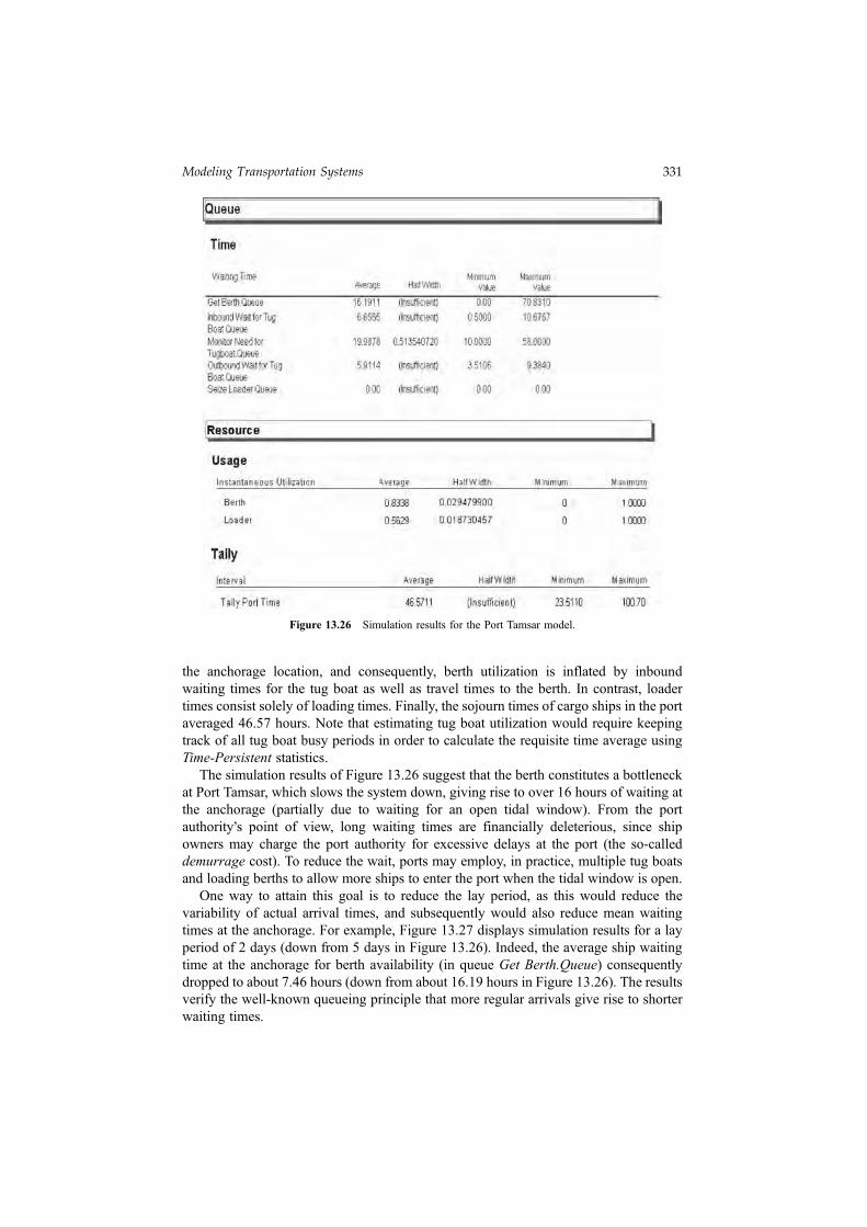
the anchorage location, and consequently, berth utilization is inflated by inboundwaiting times for the tug boat as well as travel times to the berth. In contrast, loadertimes consist solely of loading times. Finally, the sojourn times of cargo ships in the portaveraged 46.57 hours. Note that estimating tug boat utilization would require keepingtrack of all tug boat busy periods in order to calculate the requisite time average usingTime-Persistent statistics.
The simulation results of Figure 13.26 suggest that the berth constitutes a bottleneckat Port Tamsar, which slows the system down, giving rise to over 16 hours of waiting atthe anchorage (partially due to waiting for an open tidal window). From the portauthority
,s point of view, long waiting times are financially deleterious, since ship
owners may charge the port authority for excessive delays at the port (the so-calleddemurrage cost). To reduce the wait, ports may employ, in practice, multiple tug boatsand loading berths to allow more ships to enter the port when the tidal window is open.
One way to attain this goal is to reduce the lay period, as this would reduce thevariability of actual arrival times, and subsequently would also reduce mean waitingtimes at the anchorage. For example, Figure 13.27 displays simulation results for a layperiod of 2 days (down from 5 days in Figure 13.26). Indeed, the average ship waitingtime at the anchorage for berth availability (in queue Get Berth.Queue) consequentlydropped to about 7.46 hours (down from about 16.19 hours in Figure 13.26). The resultsverify the well-known queueing principle that more regular arrivals give rise to shorterwaiting times.
Figure 13.26 Simulation results for the Port Tamsar model.
Modeling Transportation Systems 331

13.4 EXAMPLE: A TOLL PLAZA
This example concerns a transportation system consisting of a toll plaza on theNew Jersey Turnpike, and aims to study the queueing delays resulting from tollcollection. The system under study is depicted in Figure 13.28.
The toll plaza consists of two exact change (EC) lanes, two cash receipt (CR) lanes, andone easy pass (EZP) lane. Arriving vehicles are classified into three groups as follows:
1. Fifty percent of all arriving cars go to EC lanes, and their normal service timedistribution is Norm(4.81, 1.01). Recall that only the non-negative valuessampled from this distribution are used by Arena (see Section 4.2).
2. Thirty percent of all arriving cars go to CR lanes, and their service time distribu-tion is 5 þ Logn(4.67, 2.26).
3. Twenty percent of all arriving cars go to EZP lanes, and their service timedistribution is 1.18 þ 4.29 � Beta(2.27, 3.02).
Figure 13.27 Simulation results for the Port Tamsar model with shorter lay periods.
TollBooths
Exact Change(EC) Lanes
EZ Pass(EZP) Lane
Cash Receipt(CR) Lanes
Incoming C
ars to Toll P
laza
Figure 13.28 A toll plaza system on the New Jersey Turnpike.
332 Modeling Transportation Systems