Embed Size (px)
Citation preview

www.erni.com
1.27 mm Connectors SMC
Catalog E 074473 12/08 Edition 7
Catalog E 074473 12/08 Edition 7
www.erni.com

Catalog E 074473 12/08 Edition 7 www.erni.com 1
1.27 mm Connectors SMCTable of Contents
Applications. . . . . . . . . . . . . . . . . . . . . . . . . . . . . . . . . . . . . . . . . . . . . . . . . . . . . . . . . . . . . . . . . . . . . . . . . . . . . . . . . . . . . . . . . . . 2Technical Features . . . . . . . . . . . . . . . . . . . . . . . . . . . . . . . . . . . . . . . . . . . . . . . . . . . . . . . . . . . . . . . . . . . . . . . . . . . . . . . . . . . . . . 3SMC at a Glance . . . . . . . . . . . . . . . . . . . . . . . . . . . . . . . . . . . . . . . . . . . . . . . . . . . . . . . . . . . . . . . . . . . . . . . . . . . . . . . . . . . . . . . 4Mating Conditions . . . . . . . . . . . . . . . . . . . . . . . . . . . . . . . . . . . . . . . . . . . . . . . . . . . . . . . . . . . . . . . . . . . . . . . . . . . . . . . . . . . . . . 6Stacking Dimensions . . . . . . . . . . . . . . . . . . . . . . . . . . . . . . . . . . . . . . . . . . . . . . . . . . . . . . . . . . . . . . . . . . . . . . . . . . . . . . . . . . . . 7Overhead Soldering. . . . . . . . . . . . . . . . . . . . . . . . . . . . . . . . . . . . . . . . . . . . . . . . . . . . . . . . . . . . . . . . . . . . . . . . . . . . . . . . . . . . . 8ERNIPRESS® Technology . . . . . . . . . . . . . . . . . . . . . . . . . . . . . . . . . . . . . . . . . . . . . . . . . . . . . . . . . . . . . . . . . . . . . . . . . . . . . . . . 9Board-on IDC Assembly Instructions . . . . . . . . . . . . . . . . . . . . . . . . . . . . . . . . . . . . . . . . . . . . . . . . . . . . . . . . . . . . . . . . . . . . . . . 10Electrical and Mechanical Characteristics . . . . . . . . . . . . . . . . . . . . . . . . . . . . . . . . . . . . . . . . . . . . . . . . . . . . . . . . . . . . . . . . . . . 11Right Angle Male Type B . . . . . . . . . . . . . . . . . . . . . . . . . . . . . . . . . . . . . . . . . . . . . . . . . . . . . . . . . . . . . . . . . . . . . . . . . . . . . . . . 14Right Angle Male Type B with Locking System. . . . . . . . . . . . . . . . . . . . . . . . . . . . . . . . . . . . . . . . . . . . . . . . . . . . . . . . . . . . . . . . 16Vertical Male Type Q . . . . . . . . . . . . . . . . . . . . . . . . . . . . . . . . . . . . . . . . . . . . . . . . . . . . . . . . . . . . . . . . . . . . . . . . . . . . . . . . . . . 18Vertical Male Pressfit Type Q . . . . . . . . . . . . . . . . . . . . . . . . . . . . . . . . . . . . . . . . . . . . . . . . . . . . . . . . . . . . . . . . . . . . . . . . . . . . . 22Right Angle Female Type Q . . . . . . . . . . . . . . . . . . . . . . . . . . . . . . . . . . . . . . . . . . . . . . . . . . . . . . . . . . . . . . . . . . . . . . . . . . . . . . 24Right Angle Female Type Q with Locking System. . . . . . . . . . . . . . . . . . . . . . . . . . . . . . . . . . . . . . . . . . . . . . . . . . . . . . . . . . . . . . 26Vertical Female Type B. . . . . . . . . . . . . . . . . . . . . . . . . . . . . . . . . . . . . . . . . . . . . . . . . . . . . . . . . . . . . . . . . . . . . . . . . . . . . . . . . . 28Board-on IDC . . . . . . . . . . . . . . . . . . . . . . . . . . . . . . . . . . . . . . . . . . . . . . . . . . . . . . . . . . . . . . . . . . . . . . . . . . . . . . . . . . . . . . . . 33Female Cable Assemblies . . . . . . . . . . . . . . . . . . . . . . . . . . . . . . . . . . . . . . . . . . . . . . . . . . . . . . . . . . . . . . . . . . . . . . . . . . . . . . . 36Part Number Index . . . . . . . . . . . . . . . . . . . . . . . . . . . . . . . . . . . . . . . . . . . . . . . . . . . . . . . . . . . . . . . . . . . . . . . . . . . . . . . . . . . . 38
2 Catalog E 074473 12/08 Edition 7 www.erni.com
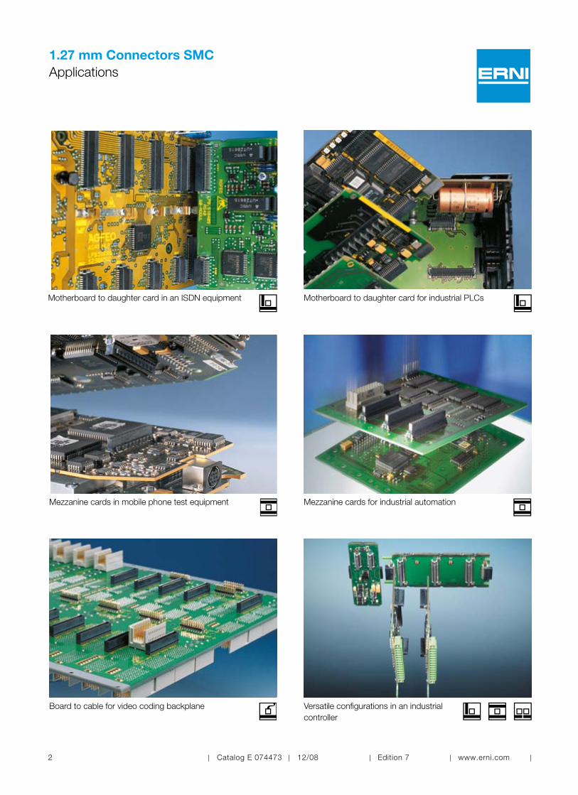
1.27 mm Connectors SMCApplications
Motherboard to daughter card in an ISDN equipment
Board to cable for video coding backplane
Mezzanine cards in mobile phone test equipment
Motherboard to daughter card for industrial PLCs
Mezzanine cards for industrial automation
Versatile configurations in an industrial controller
Catalog E 074473 12/08 Edition 7 www.erni.com 3
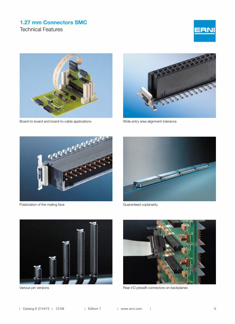
1.27 mm Connectors SMCTechnical Features
Board-to-board and board-to-cable applications Wide entry area alignment tolerance
Polarization of the mating face Guaranteed coplanarity
Various pin versions Rear I/O pressfit connectors on backplanes

4 Catalog E 074473 12/08 Edition 7 www.erni.com
1.27 mm Connectors SMCSMC at a Glance
Variable Board-to-Board Height Flexible Board-to-Board heights ranging from 8.0 mm to 20.0 mm for subassembly solutions.
Subassembly Design -Flexibility in Application Straight and right angle male and female connectors, and other available options permit many configurations and variations for maximum flexibility in designing modules and manufacturing boards.
Rear I/O connector on Multi-layer Backplanes The pressfit versions of the SMC male connectors are ideal for transferring I/O signals on the rear side of a backplane.
Simple I/O Signal Transfer with „Snap-Lock“ Female Cable Connector The female IDC cable connectors with snap-lock feature make transferring I/O signals easy and also saves space by eliminating the need for ejector latches.
Solution of Choice for Modern Subassembly Applications Printed circuit board solutions for all kind of branches.

Catalog E 074473 12/08 Edition 7 www.erni.com 5
1.27 mm Connectors SMCSMC at a Glance
Completely Automated Manufacturing of SMC ConnectorsSMC connectors are manufactured using controlled state of the art automated manufacturing equipment.
Quality Check A full inspection of the female contact apertures and coplanarity of our SMC connectors guarantees maximum reliability for your printed circuit boards.
Safe Packaging for Fully Auto-mated Assembly The antistatic tape and reel packaging not only protects the high-precision contacts of our SMC connectors, but also permits placement of connectors by automated pick and place equipment. Easy Recognition and Secure
Handling The black insulation body ensures easy visual recognition by the automatic pick and place equipment.
Reliable Insertion and Removal The metal SMT mounting clip ensures a reliable connection to the printed circuit board. As a result of its special design, it can handle high insertion and withdrawal forces. The integrated metal clips are sol-dered during the SMT process, thus elimi-nating the need for an additional operation such as rivets.
Controlled SMT Reflow Soldering Process The heat-resistant thermoplastic insula-tion body and precision coplanar contacts permit a controlled SMT soldering process.
6 Catalog E 074473 12/08 Edition 7 www.erni.com
1.27 mm Connectors SMCMating Conditions
8,0 - 20,0 2,5
4°
2°
0,7 0,7
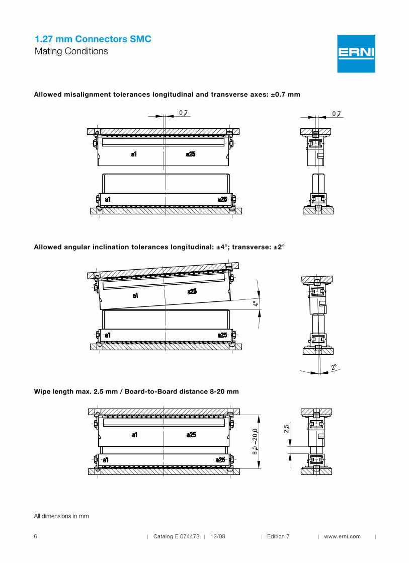
Wipe length max. 2.5 mm / Board-to-Board distance 8-20 mm
Allowed angular inclination tolerances longitudinal: ±4°; transverse: ±2°
Allowed misalignment tolerances longitudinal and transverse axes: ±0.7 mm
All dimensions in mm

Catalog E 074473 12/08 Edition 7 www.erni.com 7
1.27 mm Connectors SMCStacking Dimensions
Mezzanine
X
H *
15,40 - 16,90
3,25 13,65 16,90 - 18,40
4,85 13,65 18,50 - 20,00
4,85 9,05 13,90 - 15,40
1,75 13,65
X Y H *1,75 6,25 8,00 - 9,50
3,25 6,25 9,50 - 11,00
1,75 9,05 10,80 - 12,30
3,25 9,05 12,30 - 13,80
* Maximum Board-to-Board height is achieved taking 1,5 mm wipe length in account.
Messerleiste ( Steckhöhe X )Vertical Male ( Stacking height X )
Federleiste ( Steckhöhe Y )Vertical Female ( Stacking height Y )
Y
Motherboard to daughter card
K
10,45
min. L Y7,65 11,25 6,25
14,05 9,0515,05 18,65 13,65
K
Federleiste ( Steckhöhe Y )Vertical Female ( Stacking height Y )
Abgewinkelte Messerleiste Right Angle Male
L
N
min. N O X8,95 12,55 1,7510,45 14,05 3,2512,05 15,65 4,85
Messerleiste ( Steckhöhe X )Vertical Male ( Stacking height X )
Abgewinkelte FederleisteRight Angle Female
O
Extender card
4
8,6
min
.
4
Abgewinkelte MesserleisteRight Angle Male
Abgewinkelte FederleisteRight Angle Female
15,8
8 Catalog E 074473 12/08 Edition 7 www.erni.com
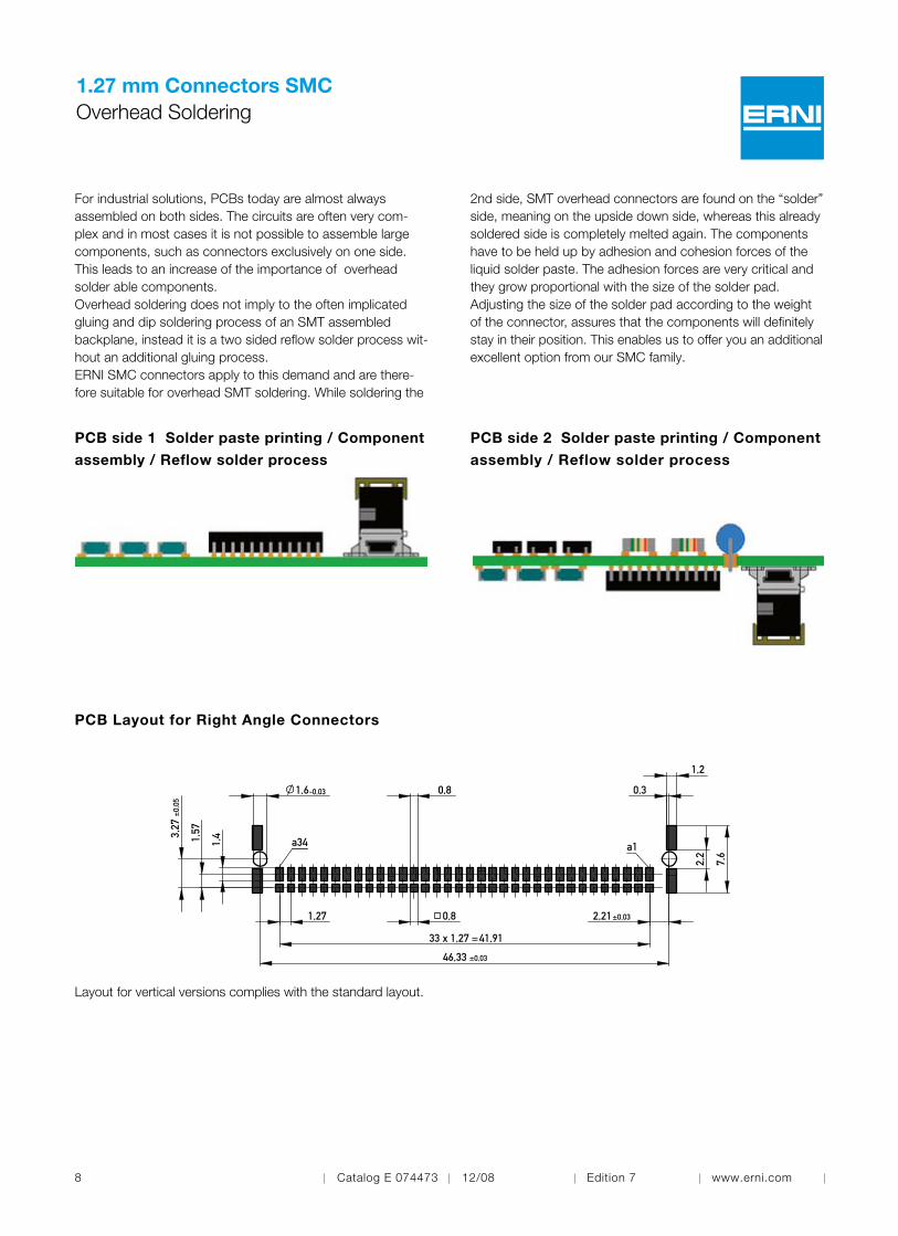
1.27 mm Connectors SMCOverhead Soldering
PCB side 1 Solder paste printing / Component
assembly / Reflow solder process
PCB side 2 Solder paste printing / Component
assembly / Reflow solder process
PCB Layout for Right Angle Connectors
For industrial solutions, PCBs today are almost always assembled on both sides. The circuits are often very com-plex and in most cases it is not possible to assemble large components, such as connectors exclusively on one side. This leads to an increase of the importance of overhead solder able components.Overhead soldering does not imply to the often implicated gluing and dip soldering process of an SMT assembled backplane, instead it is a two sided reflow solder process wit-hout an additional gluing process.ERNI SMC connectors apply to this demand and are there-fore suitable for overhead SMT soldering. While soldering the
2nd side, SMT overhead connectors are found on the “solder” side, meaning on the upside down side, whereas this already soldered side is completely melted again. The components have to be held up by adhesion and cohesion forces of the liquid solder paste. The adhesion forces are very critical and they grow proportional with the size of the solder pad. Adjusting the size of the solder pad according to the weight of the connector, assures that the components will definitely stay in their position. This enables us to offer you an additional excellent option from our SMC family.
a34 a1
2,2
0,8 0,3
1,27 2,21
1,2
1,4
33 x 1,27 =
1,57
41,91
±0,03
±0,
05
-0,03
46,33
1,6
±0,03
7,6
3,27
0,8
Layout for vertical versions complies with the standard layout.
Catalog E 074473 12/08 Edition 7 www.erni.com 9
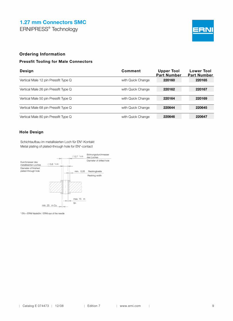
1.27 mm Connectors SMCERNIPRESS® Technology
Pressfit Tooling for Male Connectors
Lower Tool Part Number
Upper Tool Part Number
Comment
with Quick Change 220165220160
with Quick Change 220167220162
Vertical Male 12 pin Pressfit Type Q
Design
Vertical Male 26 pin Pressfit Type Q
Vertical Male 50 pin Pressfit Type Q with Quick Change 220169220164
Vertical Male 68 pin Pressfit Type Q with Quick Change 220645220644
Vertical Male 80 pin Pressfit Type Q with Quick Change 220647220646
Ordering Information
Hole Design
* EN = ERNI Nadelöhr / ERNI eye of the needle
0,05min. Restringbreite
max. 15 m
min. 25 m Cu
0,7 0,02
0,6 0,05
Restring width
Durchmesser desmetallisierten LochesDiameter of finishedplated-through hole
Bohrungsdurchmesserdes LochesDiameter of drilled hole
Sn
Schichtaufbau im metallisierten Loch für EN*-KontaktMetal plating of plated-through hole for EN*-contact
10 Catalog E 074473 12/08 Edition 7 www.erni.com
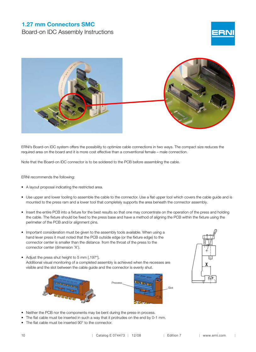
ERNI’s Board-on IDC system offers the possibility to optimize cable connections in two ways. The compact size reduces the required area on the board and it is more cost effective than a conventional female – male connection.
Note that the Board-on IDC connector is to be soldered to the PCB before assembling the cable.
ERNI recommends the following:
• Alayoutproposalindicatingtherestrictedarea.
• Useupperandlowertoolingtoassemblethecabletotheconnector.Useaflatuppertoolwhichcoversthecableguideandis mounted to the press ram and a lower tool that completely supports the area beneath the connector assembly.
• InserttheentirePCBintoafixtureforthebestresultssothatonemayconcentrateontheoperationofthepressandholding the cable. The fixture should be fixed to the press base and have a method of aligning the PCB within the fixture using the perimeter of the PCB and/or alignment pins.
• Importantconsiderationmustbegiventotheassemblytoolsavailable.Whenusinga hand lever press it must noted that the PCB outside edge (or the fixture edge) to the connector center is smaller than the distance from the throat of the press to the connector center (dimension ‘X’).
• Adjustthepressshutheightto5mm[.197“]. Additional visual monitoring of a completed assembly is achieved when the recesses are visible and the slot between the cable guide and the connector is evenly shut.
• NeitherthePCBnorthecomponentsmaybebentduringthepress-inprocess.• Theflatcablemustbeinsertedinsuchawaythatitprotrudesontheendby0-1mm.• Theflatcablemustbeinserted90°totheconnector.
1.27 mm Connectors SMCBoard-on IDC Assembly Instructions
Process
Slot

Catalog E 074473 12/08 Edition 7 www.erni.com 11
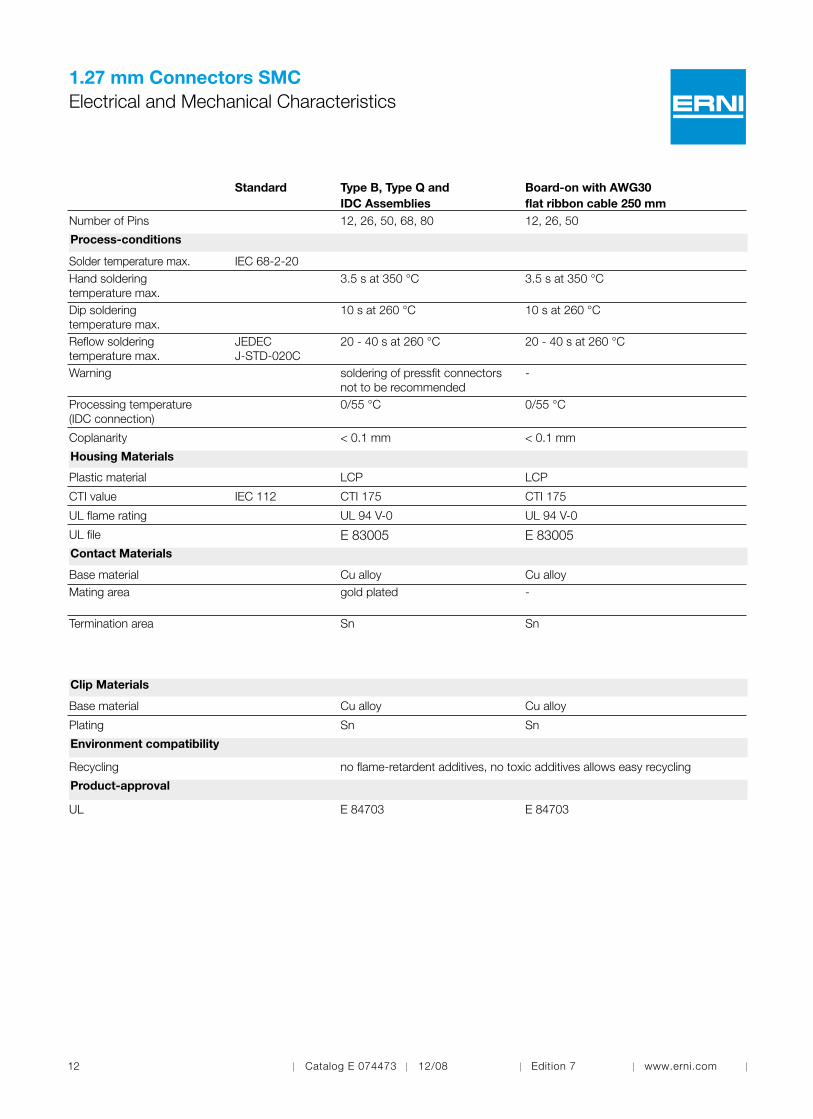
1.27 mm Connectors SMCElectrical and Mechanical Characteristics
Standard
Type B, Type Q andIDC Assemblies
Board-on IDC with AWG30flat ribbon cable 250 mm
Number of Pins 12, 26, 50, 68, 80 12, 26, 50
Technical DataClimate category
DIN EN 60068-1 test b
-55/125/56
-55/125/56
Temperature range
-55/125°C-55/105°C(IDCAssemblies)
-55/105°C
Current rating per contact
IEC60512test 5b
20°C 70°C100°C12pin 1.6 A 1.1 A 0.7 A 26pin 1.3 A 0.9 A 0.6 A 50pin 1.1 A 0.8 A 0.5 A68pin 1.0 A 0.8 A 0.5 A80pin 1.0 A 0.8 A 0.5 A
20°C 70°C100°C12pin 1.8 A 1.1 A 0.4 A 26pin 1.6 A 1.0 A 0.3 A 50pin 1.3 A 0.8 A 0.3 A
Air – and creepage distance 0.4 mm 0.4 mmOperating voltage
IEC 60664
The permissible operating voltages depend on the customer applica-tion and on the applicable or specified safety requirements.Insulation coordination according to IEC 60664-1 has to be regarded for the complete electrical device. Therefore, the maximum creepage and clearance distances of the mated connectors are specified for consideration as a part of the whole current path. In practice, reductions in creepage or clearance distances may occur due to the conductive pattern of the printed board or the wiring used, and have to be taken into account separately.As a result the creepage and clearance distances for the application may be reduced compared to those of the connector.
Dielectric strength
IEC 60512 test 4a
contact – contact 500 Vrms
contact – contact 500 Vrms
Contact resistance
IEC 60512 test 2a
< 25 mΩ< 10 mΩ (IDC clamp)
< 10 mΩ (IDC clamp)
Insulation resistance
IEC 60512 test 3a
> 104 MΩ
> 104 MΩ
Vibration, sine
IEC 60512 test 6d
10 – 2000 Hz 20g
10 – 2000 Hz 20g
Contact disturbance(while vibration test)
IEC 60512 test 2e
< 1 µs
< 1 µs
Shock, halfsine
IEC 60512 test 6c
50 g 11 ms
50 g 11 ms
Contact disturbance (while shock test)
IEC 60512 test 2e
< 1 µs
< 1 µs
Mechanical operation (mating cycles)
IEC 60512 test 9a
> 500 mating cycles
-
Insertion and withdrawal force
IEC 60512 test 13b
12pin: 6 N 68pin: 35 N26pin: 13 N 80pin: 40 N50pin: 26 N
-
Gauge retention force
IEC 60512 test 16e
0.1 N min.
-
12 Catalog E 074473 12/08 Edition 7 www.erni.com
1.27 mm Connectors SMCElectrical and Mechanical Characteristics
Standard
Type B, Type Q andIDC Assemblies
Board-on with AWG30flat ribbon cable 250 mm
Number of Pins 12, 26, 50, 68, 80 12, 26, 50
Process-conditions
Solder temperature max. IEC 68-2-20 Hand soldering temperature max.
3.5sat350°C
3.5sat350°C
Dip soldering temperature max.
10sat260°C
10sat260°C
Reflow soldering temperature max.
JEDECJ-STD-020C
20-40sat260°C
20-40sat260°C
Warning
soldering of pressfit connectors not to be recommended
-
Processing temperature(IDC connection)
0/55°C
0/55°C
Coplanarity < 0.1 mm < 0.1 mm
Housing Materials
Plastic material LCP LCP
CTI value IEC 112 CTI 175 CTI 175
ULflamerating UL94V-0 UL94V-0
ULfile E 83005 E 83005Contact Materials
Base material Cu alloy Cu alloyMating area
gold plated
-
Termination area
Sn
Sn
Clip Materials
Base material Cu alloy Cu alloy
Plating Sn Sn
Environment compatibility
Recycling no flame-retardent additives, no toxic additives allows easy recycling
Product-approval
UL E 84703 E 84703

Catalog E 074473 12/08 Edition 7 www.erni.com 13
1.27 mm Connectors SMCElectrical and Mechanical Characteristics
Standard
Cable (PVC)for Cable Assemlies
Number of Pins 12, 26, 50, 68, 80 Cable Assembly
Cross section AWG30 / 7 / 0.06 mm2
Conductor Cu wire tin-plated Marking
DIN 57207/VDE 0207
Red
Insulation PVC Shore hardness 94 ±3 (Shore A) Technical Data
Temperature range -20/105°C Current rating 0.8Aat20°C Voltag rating max. 150 V Dielectric strength 1500 Vrms Conductor resistance ≤ 350 Ω/km Insulation resistance ≥100MΩxkmat20°C Capacitance at 1 kHz ground-signal-ground 60 pF/m Inductance at 10 kHz ground-signal-ground 0.5 µH/m Impedance ground-signal-ground 75 Ω Crosstalk Cable length 3 m: NE 2.6 / FE 3.8 Propagation delay 4.5 ns/m ULflamability UL94VW-1 Product-approval
ULstyle 2678 CSA specification AWMIA105°,150VFT-1

14 Catalog E 074473 12/08 Edition 7 www.erni.com
1.27 mm Connectors SMCRight Angle Male Type B
Dimensional Drawings
All dimensions in mm.
Catalog E 074473 12/08 Edition 7 www.erni.com 15
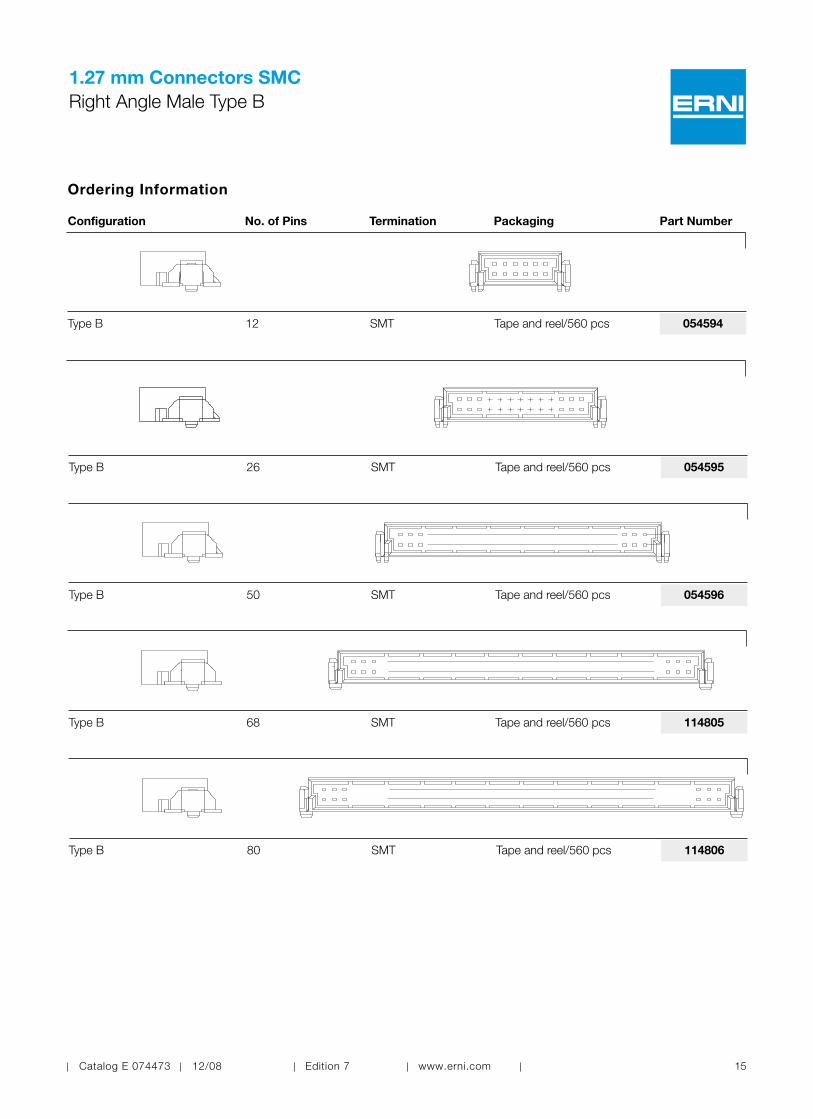
1.27 mm Connectors SMCRight Angle Male Type B
Configuration No. of Pins Termination Packaging Part Number
Ordering Information
114806Type B SMT Tape and reel/560 pcs
054594Type B SMT Tape and reel/560 pcs12
054595Type B SMT Tape and reel/560 pcs26
054596Type B SMT Tape and reel/560 pcs50
114805Type B SMT Tape and reel/560 pcs68
80
16 Catalog E 074473 12/08 Edition 7 www.erni.com
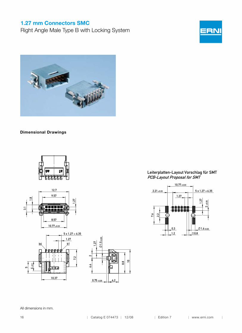
1.27 mm Connectors SMCRight Angle Male Type B with Locking System
Dimensional Drawings
b1b6
4±
0,1
7,2
10,37
1,27
5
5 x 1,27 = 6,35
12,7
9,57
8,57
3,1
10,77±0,03
1,271,
8
8,8
1,27
6,4
2
-0,0
3
4,2
1,5
0,75 -0,05
10
All dimensions in mm.
Leiterplatten-Layout Vorschlag für SMTPCB-Layout Proposal for SMT
1,27
1,27
2,21
7,6
2,2
-0,03
10,77
0,3
5 x 1,27 =
±0,03
1,2
1,6
±0,03 6,35
±0,
052
0,8

Catalog E 074473 12/08 Edition 7 www.erni.com 17
1.27 mm Connectors SMCRight Angle Male Type B with Locking System
Configuration No. of Pins Termination Packaging Part Number
Ordering Information
254273Type B SMT Tape and reel/560 pcs12

18 Catalog E 074473 12/08 Edition 7 www.erni.com
1.27 mm Connectors SMCVertical Male Type Q
Dimensional Drawings
All dimensions in mm.
Connectors with Unmated Stacking Height 1.75 mm

Catalog E 074473 12/08 Edition 7 www.erni.com 19
1.27 mm Connectors SMCVertical Male Type Q
Dimensional Drawings
Connectors with Unmated Stacking Height 3.25 mm
All dimensions in mm.

20 Catalog E 074473 12/08 Edition 7 www.erni.com
1.27 mm Connectors SMCVertical Male Type Q
Configuration No. of Pins Termination Unmated Stacking Height Packaging Part Number
Ordering Information
154818Type Q 1.75 mm Tape and reel/280 pcsSMT12
063179Type Q 3.25 mm Tape and reel/280 pcsSMT12
154819Type Q 1.75 mm Tape and reel/280 pcsSMT26
063209Type Q 3.25 mm Tape and reel/280 pcsSMT26
154820Type Q 1.75 mm Tape and reel/280 pcsSMT50
063210Type Q 3.25 mm Tape and reel/280 pcsSMT50

Catalog E 074473 12/08 Edition 7 www.erni.com 21
1.27 mm Connectors SMCVertical Male Type Q
Configuration No. of Pins Termination Unmated Stacking Height Packaging Part Number
Ordering Information
154821Type Q 1.75 mm Tape and reel/280 pcsSMT68
114807Type Q 3.25 mm Tape and reel/280 pcsSMT68
154822Type Q 1.75 mm Tape and reel/280 pcsSMT80
114808Type Q 3.25 mm Tape and reel/280 pcsSMT80
22 Catalog E 074473 12/08 Edition 7 www.erni.com
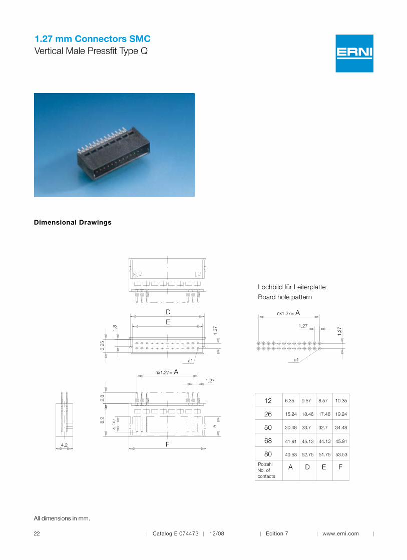
1.27 mm Connectors SMCVertical Male Pressfit Type Q
Dimensional Drawings
a1
nx1.27=
a1
nx1.27=
1,8
3,25
1,27
1,27
40,
1
5
8,2
2,8
1,27
1,27
4,2
D
E
A
F
A
68 41.91
80 49.53
45.13 44.13 45.91
52.75 51.75 53.53
Lochbild für Leiterplatte
Board hole pattern
RestringbreiteRestring width
Durchmesser desmetallisierten LochesDiameter of finishedplated-through hole
Bohrungsdurchmesserdes LochesDiameter of drilled hole
max. 15 μmSn / SnPb
min. 25 μm Cu
Schichtaufbau im metallisierten Loch für EE-KontaktMetal plating of plated-through hole for EE-contact
min. 0.1
ø0.6 ±0.05
ø0.7 ±0.02
12 6.35
26 15.24
9.57 8.57
18.46 17.46 19.24
10.35
50 30.48 33.7 32.7 34.48
PolzahlNo. ofcontacts
E FDA
All dimensions in mm.

Catalog E 074473 12/08 Edition 7 www.erni.com 23
1.27 mm Connectors SMCVertical Male Pressfit Type Q
Configuration No. of Pins Termination Unmated Stacking Height Packaging Part Number
Ordering Information
064002Type Q 3.25 mm Tube/65 pcsPressfit12
064003Type Q 3.25 mm Tube/35 pcsPressfit26
064004Type Q 3.25 mm Tube/19 pcsPressfit50
144183Type Q 3.25 mm Tube/14 pcsPressfit68
144185Type Q 3.25 mm Tube/12 pcsPressfit80

24 Catalog E 074473 12/08 Edition 7 www.erni.com
1.27 mm Connectors SMCRight Angle Female Type Q
Dimensional Drawings
All dimensions in mm.

Catalog E 074473 12/08 Edition 7 www.erni.com 25
1.27 mm Connectors SMCRight Angle Female Type Q
Configuration No. of Pins Termination Packaging Part Number
Ordering Information
154744Type Q SMT Tape and reel/560 pcs
154740Type Q SMT Tape and reel/560 pcs12
154741Type Q SMT Tape and reel/560 pcs26
154742Type Q SMT Tape and reel/560 pcs50
154743Type Q SMT Tape and reel/560 pcs68
80
26 Catalog E 074473 12/08 Edition 7 www.erni.com
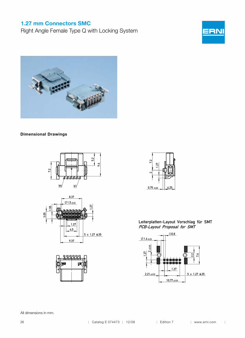
1.27 mm Connectors SMCRight Angle Female Type Q with Locking System
Dimensional Drawings
3,05
8,37
9,37
-0,03
4,5
1,27
5 x 1,27 = 6,35
1,55
1,5
1,27
b1b6
9,6
5,2
7,2
-0,05 4,25
2
0,75
1,27
7,2
3,05
8,37
9,37
-0,03
4,5
1,27
5 x 1,27 = 6,35
1,55
1,5
1,27
b1b6
9,6
5,2
7,2
-0,05 4,25
2
0,75
1,27
7,2
All dimensions in mm.
Leiterplatten-Layout Vorschlag für SMTPCB-Layout Proposal for SMT
1,6-0,03
1,27
1,27
2
6,355 x 1,27 =
±0,
05
±0,03
±0,03
0,8
2,21
10,77
2,2
7,6

Catalog E 074473 12/08 Edition 7 www.erni.com 27
1.27 mm Connectors SMCRight Angle Female Type Q with Locking System
Configuration No. of Pins Termination Packaging Part Number
Ordering Information
254262Type Q SMT Tape and reel/560 pcs12

28 Catalog E 074473 12/08 Edition 7 www.erni.com
1.27 mm Connectors SMCVertical Female Type B
Dimensional Drawings
Connectors with Unmated Stacking Height 6.25 mm
All dimensions in mm.

Catalog E 074473 12/08 Edition 7 www.erni.com 29
1.27 mm Connectors SMCVertical Female Type B
Dimensional Drawings
Connectors with Unmated Stacking Height 9.05 mm
All dimensions in mm.

30 Catalog E 074473 12/08 Edition 7 www.erni.com
1.27 mm Connectors SMCVertical Female Type B
Dimensional Drawings
Connectors with Unmated Stacking Height 13.65 mm
Ansaughaubehood
17,76
0,635
5,2
±0,0334,9
13,6
5
1,5-0,03
4,2
13,9
50,
75-0
,05
a1a25
36,8
32,5
33,5
7,2
3,05
1,55 1,27
1,27
24 x 1,27 = 30,48
All dimensions in mm.
5,5
1,27
24 x 1,27 = 30,48
Leiterplatten-Layout Vorschlag für SMTPCB-Layout Proposal for SMT
a1
7,6
-0,031,2
0,8
±0,03
±0,03
2,2
34,9
0,3
2,21
1,6
1,1
Catalog E 074473 12/08 Edition 7 www.erni.com 31
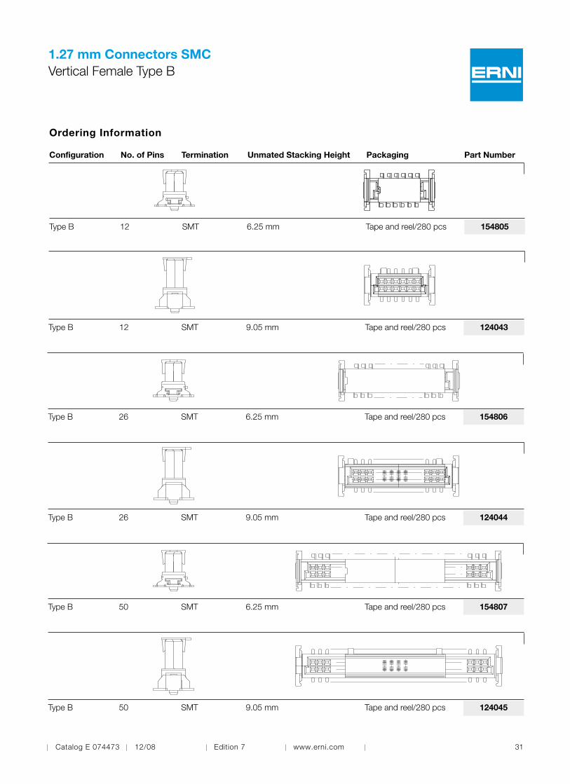
1.27 mm Connectors SMCVertical Female Type B
Configuration No. of Pins Termination Unmated Stacking Height Packaging Part Number
Ordering Information
154805Type B 6.25 mm Tape and reel/280 pcsSMT12
124043Type B 9.05 mm Tape and reel/280 pcsSMT12
154806Type B 6.25 mm Tape and reel/280 pcsSMT26
124044Type B 9.05 mm Tape and reel/280 pcsSMT26
124045Type B 9.05 mm Tape and reel/280 pcsSMT50
154807Type B 6.25 mm Tape and reel/280 pcsSMT50

32 Catalog E 074473 12/08 Edition 7 www.erni.com
1.27 mm Connectors SMCVertical Female Type B
Configuration No. of Pins Termination Unmated Stacking Height Packaging Part Number
Ordering Information
234199Type B 13.65 mm Tape and reel/170 pcsSMT50
154808Type B 6.25 mm Tape and reel/280 pcsSMT68
114803Type B 9.05 mm Tape and reel/280 pcsSMT68
154809Type B 6.25 mm Tape and reel/280 pcsSMT80
114804Type B 9.05 mm Tape and reel/280 pcsSMT80
Catalog E 074473 12/08 Edition 7 www.erni.com 33
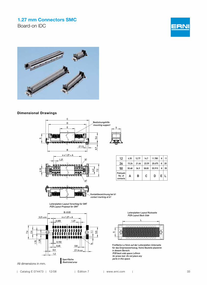
1.27 mm Connectors SMCBoard-on IDC
Dimensional Drawings
All dimensions in mm.
PCB-Layout Proposal for SMTLeiterplatten-Layout Vorschlag für SMT
a1
n x 1,27 = A
B
-0,03
3,21
1,27
7,6
±0,03
1,72 1,35
0,8
2,6
0,3
5,5
1,2
1,1
0,03
1,6
0,45
12 6,35 12,77 14,7 11,785 8 11
26 15,24 21,66 23,59 20,675 8 20
50 30,48 36,9 38,83 35,915 8 35
PohlzahlNo. of
contactsA B C D E L
PCB-Layout Back SideLeiterplatten-Layout Rückseite
Freifläche Lx 5mm auf der Leiterplatten-Unterseitefür das Einpresswerkzeug. Keine Bauteile plazierenin diesem Bereich.PCB back side space Lx5mmfor press tool. Do not place any parts in this space.
5
L
Bestückungshilfemounting support
5,6
0,7
B
5
1,5
C
D
E
SperrflächeRestricted area
Kontaktbezeichnung bei b1contact marking at b1
a1
b1
4,2
1,27
n x 1.27 = A
7,2
2,15
5
0,153
0,305

34 Catalog E 074473 12/08 Edition 7 www.erni.com
Dimensional Drawings
0,02A
n x 0,635 = B
4,2
3,8
12 10,785 6,98526 19,675 15,87550 34,915 31,115
PohlzahlNo. of
contactsA B
All dimensions in mm.
1.27 mm Connectors SMCBoard-on IDC
Catalog E 074473 12/08 Edition 7 www.erni.com 35
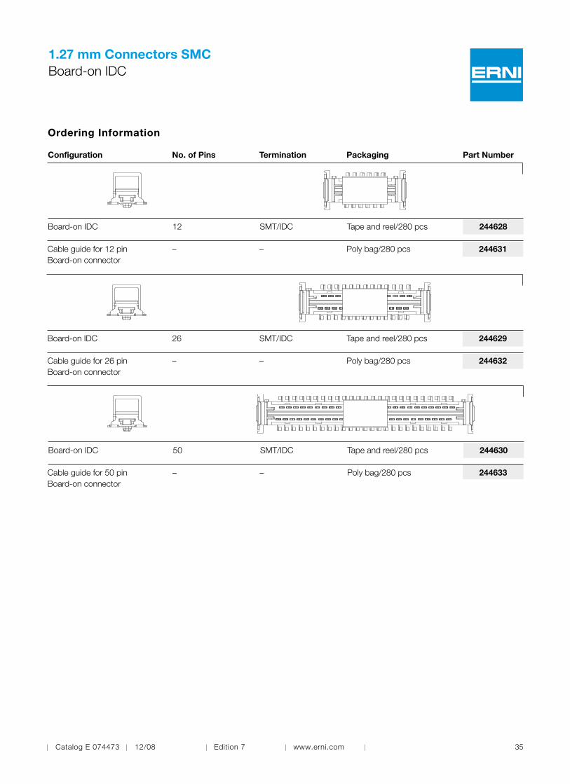
1.27 mm Connectors SMCBoard-on IDC
Configuration No. of Pins Termination Packaging Part Number
Ordering Information
244633Cable guide for 50 pin Board-on connector
– Poly bag/280 pcs
244628Board-on IDC SMT/IDC Tape and reel/280 pcs12
244631Cable guide for 12 pin Board-on connector
– Poly bag/280 pcs–
244629Board-on IDC SMT/IDC Tape and reel/280 pcs26
244632Cable guide for 26 pin Board-on connector
– Poly bag/280 pcs–
244630Board-on IDC SMT/IDC Tape and reel/280 pcs50
–
36 Catalog E 074473 12/08 Edition 7 www.erni.com
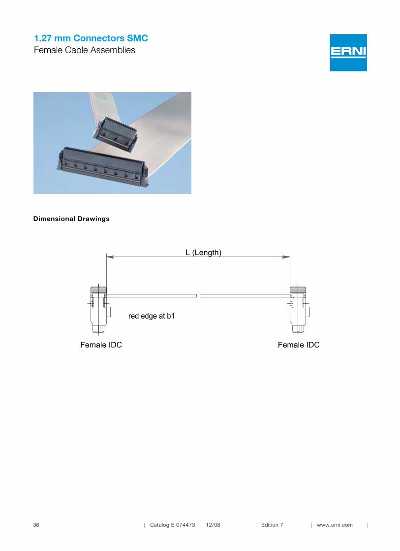
1.27 mm Connectors SMCFemale Cable Assemblies
Dimensional Drawings
L (Length)
red edge at b1
Female IDC Female IDC

Catalog E 074473 12/08 Edition 7 www.erni.com 37
1.27 mm Connectors SMCFemale Cable Assemblies
No. of Pins Length Cable Size Cable Type Part Number
173799
Ordering Information
12 100 mm AWG 30
17380012 200 mm AWG 30
17380112 300 mm AWG 30
17379626 100 mm AWG 30
17379726 200 mm AWG 30
17379826 300 mm AWG 30
17379350 100 mm AWG 30
17379450 200 mm AWG 30
17379550 300 mm AWG 30
19388868 100 mm AWG 30
19388968 200 mm AWG 30
19389068 300 mm AWG 30
19389180 100 mm AWG 30
19389280 200 mm AWG 30
19389380 300 mm AWG 30
PVC
PVC
PVC
PVC
PVC
PVC
PVC
PVC
PVC
PVC
PVC
PVC
PVC
PVC
PVC

38 Catalog E 074473 12/08 Edition 7 www.erni.com
1.27 mm Connectors SMCPart Number Index
054594 . . . . . . . . . . . . . . . . . . . . . . . . . . . . . . . . . . . . . 15054595 . . . . . . . . . . . . . . . . . . . . . . . . . . . . . . . . . . . . . 15054596 . . . . . . . . . . . . . . . . . . . . . . . . . . . . . . . . . . . . . 15063179 . . . . . . . . . . . . . . . . . . . . . . . . . . . . . . . . . . . . . 20063209 . . . . . . . . . . . . . . . . . . . . . . . . . . . . . . . . . . . . . 20063210 . . . . . . . . . . . . . . . . . . . . . . . . . . . . . . . . . . . . . 20064002 . . . . . . . . . . . . . . . . . . . . . . . . . . . . . . . . . . . . . 23064003 . . . . . . . . . . . . . . . . . . . . . . . . . . . . . . . . . . . . . 23064004 . . . . . . . . . . . . . . . . . . . . . . . . . . . . . . . . . . . . . 23114803 . . . . . . . . . . . . . . . . . . . . . . . . . . . . . . . . . . . . . 32114804 . . . . . . . . . . . . . . . . . . . . . . . . . . . . . . . . . . . . . 32114805 . . . . . . . . . . . . . . . . . . . . . . . . . . . . . . . . . . . . . 15114806 . . . . . . . . . . . . . . . . . . . . . . . . . . . . . . . . . . . . . 15114807 . . . . . . . . . . . . . . . . . . . . . . . . . . . . . . . . . . . . . 21114808 . . . . . . . . . . . . . . . . . . . . . . . . . . . . . . . . . . . . . 21124043 . . . . . . . . . . . . . . . . . . . . . . . . . . . . . . . . . . . . . 31124044 . . . . . . . . . . . . . . . . . . . . . . . . . . . . . . . . . . . . . 31124045 . . . . . . . . . . . . . . . . . . . . . . . . . . . . . . . . . . . . . 31144183 . . . . . . . . . . . . . . . . . . . . . . . . . . . . . . . . . . . . . 23144185 . . . . . . . . . . . . . . . . . . . . . . . . . . . . . . . . . . . . . 23154740 . . . . . . . . . . . . . . . . . . . . . . . . . . . . . . . . . . . . . 25154741 . . . . . . . . . . . . . . . . . . . . . . . . . . . . . . . . . . . . . 25154742 . . . . . . . . . . . . . . . . . . . . . . . . . . . . . . . . . . . . . 25154743 . . . . . . . . . . . . . . . . . . . . . . . . . . . . . . . . . . . . . 25154744 . . . . . . . . . . . . . . . . . . . . . . . . . . . . . . . . . . . . . 25154805 . . . . . . . . . . . . . . . . . . . . . . . . . . . . . . . . . . . . . 31154806 . . . . . . . . . . . . . . . . . . . . . . . . . . . . . . . . . . . . . 31154807 . . . . . . . . . . . . . . . . . . . . . . . . . . . . . . . . . . . . . 31154808 . . . . . . . . . . . . . . . . . . . . . . . . . . . . . . . . . . . . . 32154809 . . . . . . . . . . . . . . . . . . . . . . . . . . . . . . . . . . . . . 32154818 . . . . . . . . . . . . . . . . . . . . . . . . . . . . . . . . . . . . . 20154819 . . . . . . . . . . . . . . . . . . . . . . . . . . . . . . . . . . . . . 20154820 . . . . . . . . . . . . . . . . . . . . . . . . . . . . . . . . . . . . . 20154821 . . . . . . . . . . . . . . . . . . . . . . . . . . . . . . . . . . . . . 21154822 . . . . . . . . . . . . . . . . . . . . . . . . . . . . . . . . . . . . . 21173793 . . . . . . . . . . . . . . . . . . . . . . . . . . . . . . . . . . . . . 37173794 . . . . . . . . . . . . . . . . . . . . . . . . . . . . . . . . . . . . . 37173795 . . . . . . . . . . . . . . . . . . . . . . . . . . . . . . . . . . . . . 37173796 . . . . . . . . . . . . . . . . . . . . . . . . . . . . . . . . . . . . . 37173797 . . . . . . . . . . . . . . . . . . . . . . . . . . . . . . . . . . . . . 37173798 . . . . . . . . . . . . . . . . . . . . . . . . . . . . . . . . . . . . . 37173799 . . . . . . . . . . . . . . . . . . . . . . . . . . . . . . . . . . . . . 37173800 . . . . . . . . . . . . . . . . . . . . . . . . . . . . . . . . . . . . . 37173801 . . . . . . . . . . . . . . . . . . . . . . . . . . . . . . . . . . . . . 37193888 . . . . . . . . . . . . . . . . . . . . . . . . . . . . . . . . . . . . . 37193889 . . . . . . . . . . . . . . . . . . . . . . . . . . . . . . . . . . . . . 37193890 . . . . . . . . . . . . . . . . . . . . . . . . . . . . . . . . . . . . . 37193891 . . . . . . . . . . . . . . . . . . . . . . . . . . . . . . . . . . . . . 37
Part Number Page Part Number Page
193892 . . . . . . . . . . . . . . . . . . . . . . . . . . . . . . . . . . . . . 37193893 . . . . . . . . . . . . . . . . . . . . . . . . . . . . . . . . . . . . . 37220160 . . . . . . . . . . . . . . . . . . . . . . . . . . . . . . . . . . . . . . 9220162 . . . . . . . . . . . . . . . . . . . . . . . . . . . . . . . . . . . . . . 9220164 . . . . . . . . . . . . . . . . . . . . . . . . . . . . . . . . . . . . . . 9220165 . . . . . . . . . . . . . . . . . . . . . . . . . . . . . . . . . . . . . . 9220167 . . . . . . . . . . . . . . . . . . . . . . . . . . . . . . . . . . . . . . 9220169 . . . . . . . . . . . . . . . . . . . . . . . . . . . . . . . . . . . . . . 9220644 . . . . . . . . . . . . . . . . . . . . . . . . . . . . . . . . . . . . . . 9220645 . . . . . . . . . . . . . . . . . . . . . . . . . . . . . . . . . . . . . . 9220646 . . . . . . . . . . . . . . . . . . . . . . . . . . . . . . . . . . . . . . 9220647 . . . . . . . . . . . . . . . . . . . . . . . . . . . . . . . . . . . . . . 9234199 . . . . . . . . . . . . . . . . . . . . . . . . . . . . . . . . . . . . . 32244628 . . . . . . . . . . . . . . . . . . . . . . . . . . . . . . . . . . . . . 35244629 . . . . . . . . . . . . . . . . . . . . . . . . . . . . . . . . . . . . . 35244630 . . . . . . . . . . . . . . . . . . . . . . . . . . . . . . . . . . . . . 35244631 . . . . . . . . . . . . . . . . . . . . . . . . . . . . . . . . . . . . . 35244632 . . . . . . . . . . . . . . . . . . . . . . . . . . . . . . . . . . . . . 35244633 . . . . . . . . . . . . . . . . . . . . . . . . . . . . . . . . . . . . . 35254262 . . . . . . . . . . . . . . . . . . . . . . . . . . . . . . . . . . . . . 27254273 . . . . . . . . . . . . . . . . . . . . . . . . . . . . . . . . . . . . . 17

1.27 mm Connectors SMCNotes

40 Catalog E 074473 12/08 Edition 7 www.erni.com
1.27 mm Connectors SMCNotes
Catalog E 074473 12/08 Edition 7
www.erni.com
Member

©ERNIElectronicsGmbH2008•PrintedinGermany.Apolicyofcontinuousimprovementisfollowedandtherighttoalteranypublisheddatawithoutnoticeisreserved.ERNI®,
MicroStac®, MicroSpeed®, MiniBridge®, MaxiBridge®, ERmet®, ERmet ZD®, ERbic® and ERNIPRESS® are trademarks (registered or applied for in various countries) of ERNI Elec-
tronics GmbH.
ERNI Electronics GmbH Europe South America Africa JapanSeestrasse 973099 Adelberg, GermanyTel +49 7166 50-0Fax +49 7166 [email protected]
ERNI Electronics, Inc. North America Canada Mexico2201 Westwood AveRichmond, VA 23230Tel +1 804 228-4100Fax +1 804 [email protected]
ERNI Asia Holding Pte Ltd. AsiaBlk 4008 Ang Mo Kio Avenue 10#04-01/02 Techplace ISingapore 569625Tel +65 6 555 5885Fax +65 6 555 [email protected]
www.erni.com
Catalog E 074473 12/08 Edition 7