Embed Size (px)
DESCRIPTION
MGDP T 1033 0 (Spec for PAGA System)
Citation preview

Project Title
MEHAR GAS DEVELOPMENT PROJECT
Area Location Discipline Document No. Rev. Page 12 MGDP T 1033 0 2 of 31
VECO Doc. No. 20298-01-EJ12-013
TABLE OF CONTENTS
1.0 INTRODUCTION ..........................................................................................................5
1.1 General .........................................................................................................................5
1.2 Scope ...........................................................................................................................5
1.3 Definitions .....................................................................................................................6
1.4 Abbreviations ................................................................................................................6
1.5 Environmental Conditions .............................................................................................7
1.6 Device Protection..........................................................................................................7
2.0 CODES AND STANDARDS .........................................................................................8
3.0 GENERAL ....................................................................................................................9
3.1 PA System Design ........................................................................................................9
3.2 Main Functions............................................................................................................11
4.0 EQUIPMENT SPECIFICATION ..................................................................................11
4.1 PA Cabinets ................................................................................................................11
4.2 Master Control Panel ..................................................................................................12
4.3 Access Station ............................................................................................................13
4.4 Power Amplifiers .........................................................................................................13
4.5 Alarm Tone Generator ................................................................................................14
4.6 Alarm Speech Generator ............................................................................................14
4.7 Speakers.....................................................................................................................15
4.8 Control Panel ..............................................................................................................15
4.9 Loudspeakers .............................................................................................................15
4.10 Off-The-Shelf Components .........................................................................................16
5.0 ALARM TONES, PRIORITY AND SEQUENCE..........................................................16
5.1 Alarm Tones And Priority ............................................................................................16
5.2 Alarm Sequence .........................................................................................................17
6.0 ZONE DISTRIBUTION................................................................................................18

Project Title
MEHAR GAS DEVELOPMENT PROJECT
Area Location Discipline Document No. Rev. Page 12 MGDP T 1033 0 3 of 31
VECO Doc. No. 20298-01-EJ12-013
7.0 CABLES.....................................................................................................................19
7.1 Interconnecting System Cables...................................................................................19
7.2 Non-System Cables And Field Cables ........................................................................19
7.3 Field Cable Configuration............................................................................................19
7.4 Volt Drop Calculations.................................................................................................20
8.0 PA MANAGEMENT SYSTEM – PC BASED ..............................................................20
9.0 SYSTEM TEST FACILITIES.......................................................................................21
10.0 SYSTEM FLEXIBILITY...............................................................................................21
11.0 FAIL SAFE OPERATION ...........................................................................................21
12.0 OVERLOAD PROTECTION .......................................................................................22
13.0 SYSTEM CABINETS..................................................................................................22
13.1 General .......................................................................................................................22
13.2 Construction................................................................................................................22
13.3 Ventilation Requirements ............................................................................................23
13.4 Equipment Installation.................................................................................................23
13.5 Electrical Requirements ..............................................................................................24
14.0 EARTHING .................................................................................................................25
15.0 REQUIREMENTS FOR INDOOR EQUIPMENT..........................................................25
16.0 REQUIREMENTS FOR OUTDOOR DEVICES ...........................................................25
17.0 INTERFACE WITH OTHER EQUIPMENT ..................................................................26
17.1 Interface To PABX ......................................................................................................26
17.2 Interface To FGS ........................................................................................................26
17.3 Interface To PMCS .....................................................................................................26
18.0 LIGHTING PROTECTION...........................................................................................26
19.0 SYSTEM RELIABILITY AND AVAILABILITY ............................................................26
19.1 Power Supply..............................................................................................................28
20.0 INSPECTION AND TESTING .....................................................................................28
20.1 General .......................................................................................................................28
Project Title
MEHAR GAS DEVELOPMENT PROJECT
Area Location Discipline Document No. Rev. Page 12 MGDP T 1033 0 4 of 31
VECO Doc. No. 20298-01-EJ12-013
20.2 Factory Acceptance Test ............................................................................................29
20.3 PA System Functional Test .........................................................................................30
20.4 Site Acceptance Test ..................................................................................................30
20.5 Test Equipment, Tools For Commissioning.................................................................30
21.0 SPARE PARTS ..........................................................................................................31
22.0 DOCUMENTATION ....................................................................................................31

Project Title
MEHAR GAS DEVELOPMENT PROJECT
Area Location Discipline Document No. Rev. Page 12 MGDP T 1033 0 5 of 31
VECO Doc. No. 20298-01-EJ12-013
1.0 INTRODUCTION
1.1 General
PETRONAS CARIGALI (Pakistan) Ltd. (PCPL) is undertaking the development of Mehar Gas Field in Mehar Block (Block 2767-1) located in Sindh and Balochistan Provinces of Pakistan.
PCPL intends to develop the Mehar Field by installing a Gathering System, Gas Processing Facility (GPF) and Product Storage & Loading Facilities. The field facilities will be developed in two phases, Phase-I and Phase-2. Phase-1 development will cater to 55 MMSCFD of gas productions and Phase-2 will cater to 80 MMSCFD of gas productions. The expected condensate production rate is 6600 BPD for Phase-I and 7000 BPD for Phase-2. From GPF, treated sales gas will be exported through a new pipeline to existing SSGCL/SNGPL gas pipeline. Stabilized condensate and produced LPG will be exported by road tankers.
Mehar Block is located in the Kirthar Fold belt area, in the Middle Indus Basin. Mehar field is located about 190 km west of Sukkur and 400 km north of Karachi in Sindh province. The environment is arid and the terrain is mountainous. Mazarani gas field, operated by PPL is situated about 25 km to the north, while Zamzama gas field operated by BHP is situated about 70 km to the north of Mehar Field.
Mehar field consists of Pab and Ranikot formations. The wells will be connected to the new GPF through a Gathering System. There will be a total of 8 wells (4 in Pab & 4 in Ranikot) in Phase-1 and 3 additional wells (2 in Pab & 1 in Ranikot), totaling 11, in Phase-2 of the Mehar field development.
1.2 Scope
This specification covers the basic minimum requirements for the Public Address and General Alarm System for the MEHAR Gas Development Project.
This specification shall not be considered all-inclusive. The VENDOR shall submit full technical details of his standard equipment, which meet the requirements herein. Aspects of the requirements, which cannot be met, shall be identified and variances explained. This specification shall be read in conjunction with other specifications and documents indicated in the material requisition. The order of precedence of the documents shall be the following:
• Government and Statutory regulation;
• Datasheets;
• This specification;
• Company Standards (PTS);
• International Codes and Standards.

Project Title
MEHAR GAS DEVELOPMENT PROJECT
Area Location Discipline Document No. Rev. Page 12 MGDP T 1033 0 6 of 31
VECO Doc. No. 20298-01-EJ12-013
1.3 Definitions
COMPANY Petronas Carigali Pakistan Limited (PCPL) or any Third Party assigned by the COMPANY
ENGINEER Party which carries all or part of the design, engineering of the PROJECT. VECO Engineering, Abu Dhabi is the ENGINEER.
EPCC CONTRACTOR Party which carries out all or part of the design, engineering, procurement, construction, commissioning or management, of the PROJECT. EPCC CONTRACTOR includes his approved, MANUFACTURERS, SUPPLIERS, VENDORS and SUBCONTRACTORS.
MANUFACTURER/SUPPLIER/VENDOR Party/ies, which manufacture and/or supply materials, equipment and services to perform the duties as specified by the CONTRACTOR in the scope of supply.
PROJECT MEHAR GAS DEVELOPMENT PROJECT
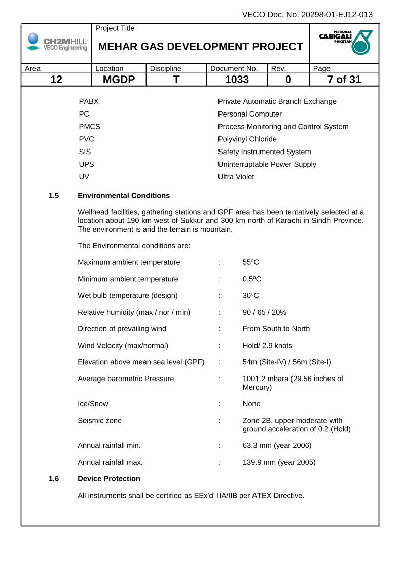
1.4 Abbreviations
BS British Standard
CCR Central Control Room
ESD Emergency Shutdown System
FAT Factory Acceptance Test
F&G Fire and Gas
GA General Alarm
GFA General Fault Alarm
GPF Gas Processing Facility
IEC International Electrotechnical Commission
IP Ingress Protection
ISO International Organization for Standardization
ITU International Telecommunication Union
MTBF Mean Time Between Failure
MTTR Mean Time to Repair
PA Public Address
Project Title
MEHAR GAS DEVELOPMENT PROJECT
Area Location Discipline Document No. Rev. Page 12 MGDP T 1033 0 7 of 31
VECO Doc. No. 20298-01-EJ12-013
PABX Private Automatic Branch Exchange
PC Personal Computer
PMCS Process Monitoring and Control System
PVC Polyvinyl Chloride
SIS Safety Instrumented System
UPS Uninterruptable Power Supply
UV Ultra Violet
1.5 Environmental Conditions
Wellhead facilities, gathering stations and GPF area has been tentatively selected at a location about 190 km west of Sukkur and 300 km north of Karachi in Sindh Province. The environment is arid the terrain is mountain.
The Environmental conditions are:
Maximum ambient temperature : 55ºC
Minimum ambient temperature : 0.5ºC
Wet bulb temperature (design) : 30ºC
Relative humidity (max / nor / min) : 90 / 65 / 20%
Direction of prevailing wind : From South to North
Wind Velocity (max/normal) : Hold/ 2.9 knots
Elevation above mean sea level (GPF) : 54m (Site-IV) / 56m (Site-l)
Average barometric Pressure : 1001.2 mbara (29.56 inches of Mercury)
Ice/Snow : None
Seismic zone : Zone 2B, upper moderate with ground acceleration of 0.2 (Hold)
Annual rainfall min. : 63.3 mm (year 2006)
Annual rainfall max. : 139.9 mm (year 2005)
1.6 Device Protection
All instruments shall be certified as EEx’d’ IIA/IIB per ATEX Directive.

Project Title
MEHAR GAS DEVELOPMENT PROJECT
Area Location Discipline Document No. Rev. Page 12 MGDP T 1033 0 8 of 31
VECO Doc. No. 20298-01-EJ12-013
Detector & device enclosures, in field, shall be dust proof, weather proof to IP 65, as a minimum. All external surfaces shall be suitably painted for corrosion protection.
Instruments shall be selected based on Area classification drawings by Electrical (document numbers will be provided later).
2.0 CODES AND STANDARDS
Codes, specifications and standards referred to within this specification, form a part of the requirements of this specification in a manner and to the extent specified within those codes and standards.
Unless otherwise specified, the latest edition or revision to these codes specifications, and standards in force at the time of request for quotation and/or Purchase Order shall apply.
No deviations from the Codes and Standards listed in this document will be allowed unless such deviations are clearly identified in the bids, with the reasoning. In addition, they must be approved in writing by COMPANY.
PTS 32.71.00.10 Plant telecommunication
PTS 32.71.00.11 Telecommunication standards
PTS 32.71.00.16 Design and installation of telephone cabling
PTS 32.71.00.30 Structured cabling system for telecommunication
BS-5345 Code of practice for Selection, Installation and maintenance of Electrical Apparatus for use in Potentially Explosive Atmosphere.
BS-6259 Code of practice for the design, planning, installation, testing and maintenance of sound systems.
BS-5428 Methods for specifying and measuring the characteristics of sound system equipment.
BS-5839 Fire detection alarm systems for buildings.
BS-4196 Sound power levels of noise source.
BS-6840 Sound system equipment. Methods for specifying and measuring general characteristics used for equipment performance.
BS-6701 Installation of Apparatus intended for connection to certain telecommunication.
Project Title
MEHAR GAS DEVELOPMENT PROJECT
Area Location Discipline Document No. Rev. Page 12 MGDP T 1033 0 9 of 31
VECO Doc. No. 20298-01-EJ12-013
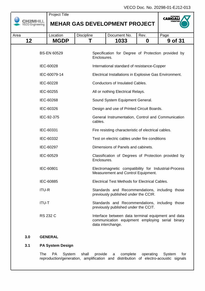
BS-EN 60529 Specification for Degree of Protection provided by Enclosures.
IEC-60028 International standard of resistance-Copper
IEC-60079-14 Electrical Installations in Explosive Gas Environment.
IEC-60228 Conductors of Insulated Cables.
IEC-60255 All or nothing Electrical Relays.
IEC-60268 Sound System Equipment General.
IEC-60326 Design and use of Printed Circuit Boards.
IEC-92-375 General Instrumentation, Control and Communication cables.
IEC-60331 Fire resisting characteristic of electrical cables.
IEC-60332 Test on electric cables under fire conditions
IEC-60297 Dimensions of Panels and cabinets.
IEC-60529 Classification of Degrees of Protection provided by Enclosures.
IEC-60801 Electromagnetic compatibility for Industrial-Process Measurement and Control Equipment.
IEC-60885 Electrical Test Methods for Electrical Cables.
ITU-R Standards and Recommendations, including those previously published under the CCIR.
ITU-T Standards and Recommendations, including those previously published under the CCIT.
RS 232 C Interface between data terminal equipment and data communication equipment employing serial binary data interchange.
3.0 GENERAL
3.1 PA System Design
The PA System shall provide a complete operating System for reproduction/generation, amplification and distribution of electro-acoustic signals
Project Title
MEHAR GAS DEVELOPMENT PROJECT
Area Location Discipline Document No. Rev. Page 12 MGDP T 1033 0 10 of 31
VECO Doc. No. 20298-01-EJ12-013
(speech and alarm tones). The System shall be so designed that a fault in any part of the System would not prevent effective operation of the System.
The System shall be designed and installed as a dual System i.e. all control, microprocessor/electronic systems and generation equipment shall be duplicated. Automatic and manual switchover from one System to the other System shall be possible.
Speakers in any one paging zone of the Facility shall be powered by two dedicated power amplifiers, with approximately half the number of speakers from main amplifier (Circuit 1) and the other half of speakers from the duplicated amplifier (Circuit 2) on another rack. Connections (looping) of speakers are arranged such that a line fault or failure on one loop (say from Circuit 1) will still allow sufficient coverage of announcements from the corresponding Circuit 2 operating from the other amplifier rack (Circuit 2).
A fault in any one amplifier shall initiate an automatic changeover to a common standby amplifier.
The amplifiers shall be configured such that its maximum power loading does not exceed 70% of its rated power output.
The wiring shall be installed in two separate cable networks for system integrity in the event of fault or fire. The two wiring routes connected to 2 loops of speakers (Circuit 1 and Circuit 2) serving a particular zone shall be on separate cable trays, over different cable routes, from 2 separate junction boxes (JBs) fixed at separate locations.
The PA shall provide a sufficiently low level of acoustic distortion to ensure minimum listening fatigue.
The audio levels at a distance of 2 metre shall be as follows:
Sound Level: 65 dBA or +5dBA above background noise whichever is greater at all indoor and outdoor areas (maximum level shall not exceed 100dBA). 75 dBA at mustering station (max.) predicted background noise shall be identified to satisfy the recommended level sound.
VENDOR shall submit calculations to prove that the audio levels as specified are achieved.
The System shall be designed to withstand continuous full load operations for a minimum of 3 hours under adverse conditions.
For each type of the Equipment, there shall be no interference or interface problems both within the Equipment type and/or between the Equipment type and other similar or non similar Equipment/System.
VENDOR shall provide COMPANY with a complete detailed design of the System for all the facilities together with all design criteria on which the design has been based.
Project Title
MEHAR GAS DEVELOPMENT PROJECT
Area Location Discipline Document No. Rev. Page 12 MGDP T 1033 0 11 of 31
VECO Doc. No. 20298-01-EJ12-013
VENDOR shall provide COMPANY with all relevant brochures and necessary calculations, drawings, schematics.
3.2 Main Functions
The PA system shall fulfill the following main functions:
• Broadcast "Prepare to Abandon” Facility's alarm tone and bilingual message;
• Broadcast "General Facility Alarm” (GA) alarm tone and bilingual message;
• Broadcast Process Alarm/Messages (signals from PMCS);
• Broadcast Emergency Announcement;
• Broadcast Normal PA Messages and test tone;
• Interface to Facility telephone exchange (PABX) for telephone paging;
• Interface to PMCS (PA status/faults to be displayed on PMCS;
• Interface with Radio and PABX system;
• Interface to F & G system.
4.0 EQUIPMENT SPECIFICATION
4.1 PA Cabinets
The PA cabinets shall have rack-mounted amplifiers, alarm tone generators, alarm speech generators and other necessary equipment. All control and generation equipment shall be duplicated with automatic and manual changeover facilities. Cabling shall follow separate routes, through separate multi-cable transits (MCTs).
The system cabinets shall be installed in the CCR and shall be floor standing-type with bottom cable entry.
The PA cabinets shall interface to the following and perform the desired functions:
• Actuating signals from / to the PA Master Control Panel, PA Access Stations, PMCS, FGS and PABX;
• Output selection of paging zones by an external control, allowing announcement by selecting any desired zone;
• Actuating signals from FGS to generate the GA alarm tone;
• A monitoring system capable of indicating and displaying minor and major faults at various stages (i.e. self diagnostic);

Project Title
MEHAR GAS DEVELOPMENT PROJECT
Area Location Discipline Document No. Rev. Page 12 MGDP T 1033 0 12 of 31
VECO Doc. No. 20298-01-EJ12-013
• System test facilities.
4.2 Master Control Panel
The Master Control Panel shall be capable of full control over the System with indicator lights, indicating system status.
The Master Control Panel shall be suitable for flush mounting on the PMCS Operator's Console (supplied by others) and located in the Central Control Room CCR.
The panel shall have push button switches and be able to perform, but not be limited to, the following functions:
• Paging zone selection buttons with indicator lights;
• Alarm tone override facility for Emergency Announcement - individual zone paging and all-zone paging pushbutton switches;
• Gooseneck type microphone;
• Lamp test;
• Alarm Reset;
• Fault Accept.
Indicators for each alarm tone shall be provided on the panel, with outputs to control external circuits for each of the alarm tones.
Each tone indicator shall stay energized upon the initiation of a tone of a higher priority. A beeper shall also be provided to indicate alarm or fault conditions.
Master control panel shall have a high quality noise cancelling, gooseneck dynamic type microphone, and the following backlighted switches/pushbuttons:
• Emergency announcement : Manual selection of zones to be addressed or any combination of these or all zones.
• Switches/ pushbuttons : Manual selection of corresponding zones with associated lights.
The purpose of these backlights is to indicate when the facility of its associated switch is being used at any PA control point, and also, to confirm that any free facility selected actually gains access to that facility. Therefore, these lights shall either confirm access or indicate its facility is busy. Indications shall also be given to identify which speaker zones have been selected.
A 'press to talk' button, non-illuminated type, is required to be operated by momentary contact for the purpose of over-riding any of the six priority selections.

Project Title
MEHAR GAS DEVELOPMENT PROJECT
Area Location Discipline Document No. Rev. Page 12 MGDP T 1033 0 13 of 31
VECO Doc. No. 20298-01-EJ12-013
Alarm reset pushbutton cancels the alarm annunciation when depressed. Cancellation of alarms (e.g. auto activation via input from Fire & Gas panel), shall only be possible when the initiating device has normalized.
A push-to-test button (lamp test) shall be provided on the panel to enable filament test on all lights simultaneously. The design shall provide for ease of access for maintenance purposes should a pushbutton lamp require changing.
4.3 Access Station
The exact number of Access Stations (Control Room, Operator Room) required to be determined during detailed engineering shall have pushbutton switches and be able to perform, as a minimum, the following functions:
• Override facility for Emergency announcement to all zones of the Facility;
• Paging into all zones of the Facility (except sleeping quarters);
• Lamp test.
Each station shall have a high quality integral or hand held/fist noise compensated microphone. It shall have pushbutton(s) with spring activated release switches and one confirmation/busy light.
The common access stations shall have a gooseneck dynamic type microphone and be suitable for wall mounting. This access station is for normal PA broadcast and is limited to the non-accommodation, common areas in the living quarters only, with no override facility. Suitable volume control switch shall be incorporated with this access station.
4.4 Power Amplifiers
The amplifiers shall be arranged in two separate racks. Every zone of the Facility shall be fed from separate amplifiers, one from each rack.
The amplifiers outputs shall be independent of each other and shall be distributed by individual cable run, where all parts of the cable run follow separate routes and leave the equipment room via separate transits. In the event of a single equipment or cable failure, no area will be without coverage.
The amplifiers shall be capable of continuous operation at maximum rated output. The amplifiers shall be interchangeable and outputs shall be 100V AC to line.
The microphone inputs to the amplifiers should be capable of accepting a minimum input of -50 dBm (@ maximum sensitivity) with an input impedance of 600 ohms (balanced) by use of internal links.
The output power from each amplifier should be of the order of 300 watts. The recommended output impedance shall be of 600 ohms (balanced) and must be capable of operating safely into a short-circuited load.
Project Title
MEHAR GAS DEVELOPMENT PROJECT
Area Location Discipline Document No. Rev. Page 12 MGDP T 1033 0 14 of 31
VECO Doc. No. 20298-01-EJ12-013
Regulation shall be better than 3 dB. Noise level shall be greater than 60 dB below full output. Frequency response shall be 50 Hz to 14 kHz ± 3 dB referred to test tone level @ 1 kHz. Tone control is required with ± 10 dB at 100 Hz and ± 10 dB at 10 kHz.
Distortion expressed as a total harmonic of 1 kHz shall be typically 1% at nominal output power.
The amplifiers shall be immune to open and short circuit conditions on its output when under full drive conditions on its input. If protection circuits are activated the amplifier shall return to normal operation as soon as faults are cleared. It shall also be protected against thermal overload.
Tailoring (equalization) of the frequency response of the System and band-pass filtering is required to optimize the use of the amplifier power and to improve the overall signal-to-noise ratio. It shall be possible to attenuate (manually) signals below 300Hz, between 10 dB and 20 dB per octave.
It shall be possible to attenuate signals above either 5 kHz or 10 kHz (selection is required), between 5 dB and 20 dB relative to 1 kHz.
4.5 Alarm Tone Generator
The unit or card shall be rack mounted and shall provide the facility to generate up to a minimum of 6 unique and separate alarm tone signals that are capable of being broadcasted over the speaker system. Refer to section 5.1 for details of alarm tones and priority.
The alarm tones are to be initiated manually by momentary contact pushbuttons with integral indicator lamps or automatically by external control by momentarily opening the normally closed contacts wired to the priority level terminal corresponding to that tone. The lamps are to utilize a twin-filament arrangement and are required to operate when the associated selection takes place.
All tones are to be distinctive and of such frequencies that they will be clearly discernible above the Facility ambient noise levels and frequencies.
The alarm tone generators shall be modular, plug-in units or cards and shall be programmable.
4.6 Alarm Speech Generator
The capability to broadcast speech in English and Urdu shall be provided. The alarm tones shall be interspersed with alarm speech/phrases.
The alarm tone volume output shall be reduced to maximum of 25% to permit broadcast of alarm speech/phrases, enabling alarm speech to be heard at full volume with alarm tones at 25% level in the background.
Project Title
MEHAR GAS DEVELOPMENT PROJECT
Area Location Discipline Document No. Rev. Page 12 MGDP T 1033 0 15 of 31
VECO Doc. No. 20298-01-EJ12-013
The alarm tone shall not be shut off completely. Time span between alarm tones/speech shall be user selected (0-3 seconds field configurable). The alarm phrases recorded in the alarm speech generator card shall include:
English and Urdu
• Prepare to abandon Facility;
• Fire and Gas Alarm.
The system shall give the capability to override alarm tones in order to make Emergency Announcements. The override level shall be programmable.
4.7 Speakers
The speakers shall be installed at the locations as specified on the layout (to be finalized in detailed engineering).
Appropriate speakers shall be provided for indoor and outdoor locations.
VENDOR shall be responsible for the final layout and orientation of the speakers and indicate the wattage tappings and corresponding sound levels at each location in order to ensure that broadcasts and alarm signals shall be clearly heard in all areas of the Facility. VENDOR shall submit a list of the sound pressure levels (measured in dBA at one metre) anticipated from the operational speaker system for all indoor and outdoor areas. Performance figures and technical data for speakers, driver units, etc., shall be submitted in the bid. VENDOR shall ensure that the PA system sound pressure levels are as specified. Predicted background noise level for all affected areas to be submitted. Remote setting of speaker (wattage) tappings shall be possible.
VENDOR shall include an optional price for addressable speakers complete with associated electronics for the interrogation system, in his bid. (Addressable speakers shall include feature to detect faulty speakers).
4.8 Control Panel
Control panel shall consist of a loudspeaker with volume control knob, a microphone, press-to-talk button and for larger applications, a zone selector switch or a push-button unit. The control panel should include the ability to broadcast pre-recorded tones and emergency messages. This is particularly applicable in multilingual environments.
4.9 Loudspeakers
In order to reduce the maximum volume, several small loudspeakers should be installed (distributed over the area) rather than a few large ones. The speakers shall comply with the respective Area Classification and IP rating. The system shall be designed so that the audibility is not reduced by the sound arriving from different loudspeakers located at different distances. The produced sound level shall be at least 5 dB higher than the local (plant) noise. All loudspeakers shall be correctly phased at the time of manufacture with clear indication at the connectors.
Project Title
MEHAR GAS DEVELOPMENT PROJECT
Area Location Discipline Document No. Rev. Page 12 MGDP T 1033 0 16 of 31
VECO Doc. No. 20298-01-EJ12-013
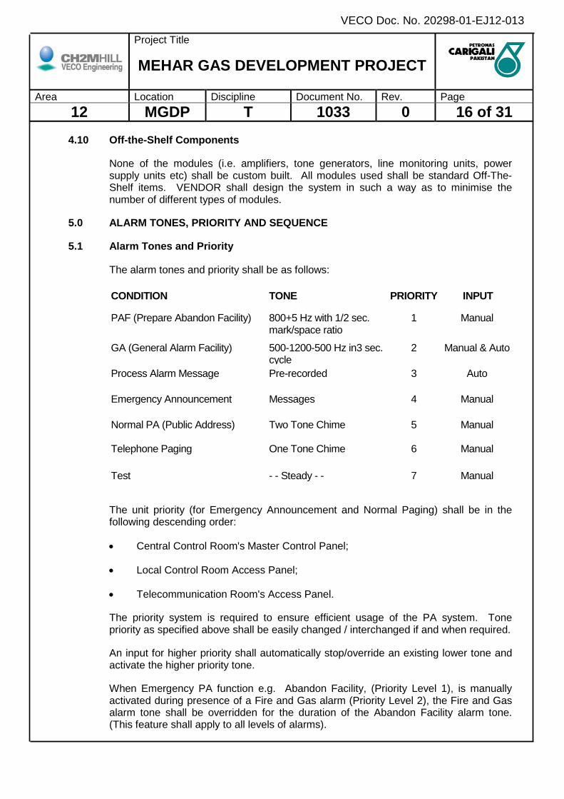
4.10 Off-the-Shelf Components
None of the modules (i.e. amplifiers, tone generators, line monitoring units, power supply units etc) shall be custom built. All modules used shall be standard Off-The-Shelf items. VENDOR shall design the system in such a way as to minimise the number of different types of modules.
5.0 ALARM TONES, PRIORITY AND SEQUENCE
5.1 Alarm Tones and Priority
The alarm tones and priority shall be as follows:
CONDITION TONE PRIORITY INPUT
PAF (Prepare Abandon Facility) 800+5 Hz with 1/2 sec. mark/space ratio
1 Manual
GA (General Alarm Facility) 500-1200-500 Hz in3 sec. cycle
2 Manual & Auto
Process Alarm Message Pre-recorded 3 Auto
Emergency Announcement Messages 4 Manual
Normal PA (Public Address) Two Tone Chime 5 Manual
Telephone Paging One Tone Chime 6 Manual
Test - - Steady - - 7 Manual
The unit priority (for Emergency Announcement and Normal Paging) shall be in the following descending order:
• Central Control Room's Master Control Panel;
• Local Control Room Access Panel;
• Telecommunication Room's Access Panel.
The priority system is required to ensure efficient usage of the PA system. Tone priority as specified above shall be easily changed / interchanged if and when required.
An input for higher priority shall automatically stop/override an existing lower tone and activate the higher priority tone.
When Emergency PA function e.g. Abandon Facility, (Priority Level 1), is manually activated during presence of a Fire and Gas alarm (Priority Level 2), the Fire and Gas alarm tone shall be overridden for the duration of the Abandon Facility alarm tone. (This feature shall apply to all levels of alarms).

Project Title
MEHAR GAS DEVELOPMENT PROJECT
Area Location Discipline Document No. Rev. Page 12 MGDP T 1033 0 17 of 31
VECO Doc. No. 20298-01-EJ12-013
When an Emergency Announcement (Priority 4) is selected during the presence of any higher priority tone alarms, the tone alarm shall be reduced to a lower audio level, after time delay, for the duration of the announcement.
The time delay shall be controlled by a timer which shall be an integral part of the main/central PA equipment. It shall be possible to vary the pre-set delay from 1 to 30 seconds.
The tone muting shall be automatically controlled for a period of approximately 30 seconds and activated by relay contacts from the System. Tone muting level shall be adjustable from 6 dB to infinity. Permanent muting action shall be prevented.
When a higher priority alarm condition arises while the Emergency Announcement is being used (during lower priority alarm), the higher priority alarm shall override the Emergency Announcement and continue to broadcast the higher priority alarm tone for the pre-set time as stated before the Emergency Announcement function can once again be used.
The selection of normal paging/test function during an alarm annunciation shall not be possible except during the localized Process Alarm. During localized Process Alarm, normal paging shall still be possible to other areas except the affected area(s) and the sleeping areas. The normal paging access is from the PA control panels or the telephone extensions.
This priority arrangement is for ensuring that the activated alarm having the highest assigned priority level is broadcasted / annunciated and that lower priority alarms are muted. Hence, this priority arrangement assures that only the most urgent alarm will be heard at any one time.
5.2 Alarm Sequence
The alarm pattern for the visual and audible GA and PA shall be unique and in accordance with the table below:
Reset Alarm Signal
Alarm Activated Initiating Source
Not Cleared Initiating Source
Cleared
Public Announcement (Mute Signal
from PA
PAF (Prepare abandon Facility)
Lights (red) flashing
PAF Tone
Lights flashing Audible on
Lights off. Audible off.
Lights flashing. Audible off.
GFA (General Facility Alarm)
Lights (red) flashing GA Tone
Lights flashing Audible on
Lights off. Audible off.
Lights flashing. Audible off.
Project Title
MEHAR GAS DEVELOPMENT PROJECT
Area Location Discipline Document No. Rev. Page 12 MGDP T 1033 0 18 of 31
VECO Doc. No. 20298-01-EJ12-013
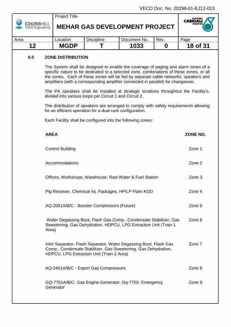
6.0 ZONE DISTRIBUTION
The System shall be designed to enable the coverage of paging and alarm tones of a specific nature to be dedicated to a selected zone, combinations of these zones, or all the zones. Each of these zones will be fed by separate cable networks, speakers and amplifiers (with a corresponding amplifier connected in parallel) for changeover.
The PA speakers shall be installed at strategic locations throughout the Facility’s, divided into various loops per Circuit 1 and Circuit 2.
The distribution of speakers are arranged to comply with safety requirements allowing for an efficient operation for a dual rack configuration.
Each Facility shall be configured into the following zones:
AREA ZONE NO.
Control Building Zone 1
Accommodations Zone 2
Offices, Workshops, Warehouse, Raw Water & Fuel Station Zone 3
Pig Receiver, Chemical Inj. Packages, HP/LP Flare KOD Zone 4
AQ-2001A/B/C - Booster Compressors (Future) Zone 5
Water Degassing Boot, Flash Gas Comp., Condensate Stabilizer, Gas Sweetening, Gas Dehydration, HDPCU, LPG Extraction Unit (Train 1 Area)
Zone 6
Inlet Separator, Flash Separator, Water Degassing Boot, Flash Gas Comp., Condensate Stabilizer, Gas Sweetening, Gas Dehydration, HDPCU, LPG Extraction Unit (Train 2 Area)
Zone 7
AQ-2401A/B/C - Export Gas Compressors Zone 8
GQ-7701A/B/C- Gas Engine Generator, Gq-7702- Emergency Generator
Zone 9

Project Title
MEHAR GAS DEVELOPMENT PROJECT
Area Location Discipline Document No. Rev. Page 12 MGDP T 1033 0 19 of 31
VECO Doc. No. 20298-01-EJ12-013
AQ-5901- Nitrogen Gen. Unit, AQ-5601A/B-Hot Oil Pkg. Zone 10
V-2705A/B/C-Lpg Bullets, P-3301A/B/C/D/E-Condenstae Ldg. Pumps Zone 11
A-2701A/B/C-Lpg Loading Bays, A-3301A/B/C/D/E/F-Condensate Ldg. Bays
Zone 12
A-2701A/B/C-Lpg Loading Bays, A-3301A/B/C/D/E/F-Condensate Ldg. Bays
Zone 13
The PA System (except Process Alarm) shall cover all recreation, kitchen area and offices in the non-accommodation areas.
In the accommodation (sleeping) areas, only Priority 1 and 2 of the alarm tones shall be broadcasted. Emergency Announcements (priority 4) will only cover these areas at pre-selected zone buttons.
Paging zones shall be field configurable (without the requirement for special tools, cables etc) to enable flexibility for future re-zoning.
VENDOR shall provide a facility to mute the audible alarm tones in the CCR Central Control Room and Telecommunication Operator Room In this instance, the strobe lights in these rooms shall continue to flash.
7.0 CABLES
7.1 Interconnecting System Cables
VENDOR shall provide all interconnecting system cables within the PA System Panels. This includes the system cables between the PA Cabinets the remote Master Control Panel/Access Stations.
All system cables shall comply to IEC 60331 and IEC 60332, Part 3, Category A. VENDOR shall submit specifications of all cables supplied.
7.2 Non-System Cables and Field Cables
All non-system cables and field cables shall be supplied by others. VENDOR shall specify any special cable characteristics e.g. number of twists per meter, shielding etc.
7.3 Field Cable Configuration
Cabling to speakers shall be dual loops to each area such that if one loop is faulty the area is still adequately covered by the second loop.

Project Title
MEHAR GAS DEVELOPMENT PROJECT
Area Location Discipline Document No. Rev. Page 12 MGDP T 1033 0 20 of 31
VECO Doc. No. 20298-01-EJ12-013
7.4 Volt Drop Calculations
VENDOR shall confirm by detailed voltage drop calculations, the suitability of the proposed cable size for both the speakers and strobe lights. If VENDOR's calculations conclude that the selected field cables will not meet the requirements of the field devices, this shall be stated explicitly in the bid and an alternate size shall be proposed. Voltage drop calculations shall be submitted.
(The selected cable size for speakers is 1.5mm2 and for strobe lights is 2.5mm2).
8.0 PA MANAGEMENT SYSTEM – PC BASED
A PA Management System shall be included in the design to enable faults to be identified quickly throughout the system (e.g. faults in amplifiers and loudspeaker lines).
The System shall monitor the outputs from different amplifiers, alarm and speech generators and give alarm when an abnormal situation arises.
Comprehensive self test and diagnostics facilities shall be provided. All faults shall be identified and alarmed. The diagnostics shall clearly identify the faulty module. The results of the diagnostics shall be made available on the panel fascia.
PA Management System shall indicate any faulty by visualizing in affected part. This shall include but not be limited to the following:
• Microphone Station;
• Remote Rack;
• Inputs;
• Access Panel;
• External Alarm Inputs;
• Central Rack;
• Fans;
• CPU (control section and analog section);
• Speaker Loops;
• Amplifiers;
• Power Supply Units;
• Tone generator, etc.
Project Title
MEHAR GAS DEVELOPMENT PROJECT
Area Location Discipline Document No. Rev. Page 12 MGDP T 1033 0 21 of 31
VECO Doc. No. 20298-01-EJ12-013
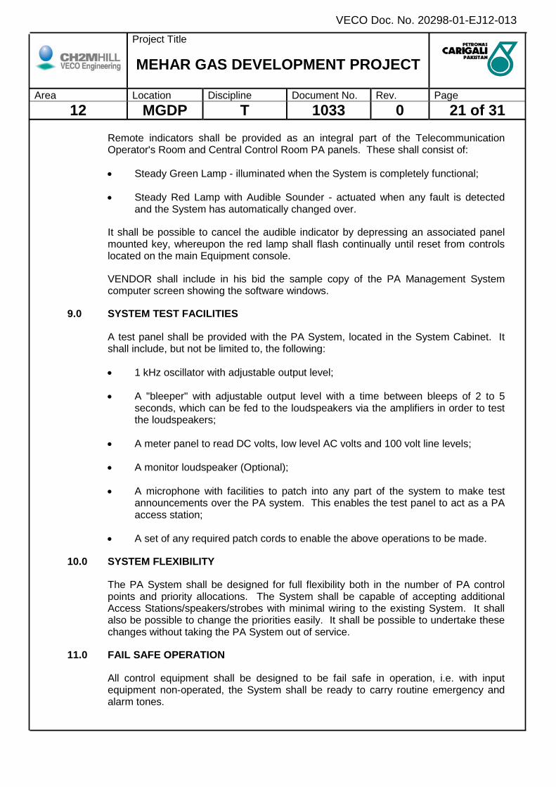
Remote indicators shall be provided as an integral part of the Telecommunication Operator's Room and Central Control Room PA panels. These shall consist of:
• Steady Green Lamp - illuminated when the System is completely functional;
• Steady Red Lamp with Audible Sounder - actuated when any fault is detected and the System has automatically changed over.
It shall be possible to cancel the audible indicator by depressing an associated panel mounted key, whereupon the red lamp shall flash continually until reset from controls located on the main Equipment console.
VENDOR shall include in his bid the sample copy of the PA Management System computer screen showing the software windows.
9.0 SYSTEM TEST FACILITIES
A test panel shall be provided with the PA System, located in the System Cabinet. It shall include, but not be limited to, the following:
• 1 kHz oscillator with adjustable output level;
• A "bleeper" with adjustable output level with a time between bleeps of 2 to 5 seconds, which can be fed to the loudspeakers via the amplifiers in order to test the loudspeakers;
• A meter panel to read DC volts, low level AC volts and 100 volt line levels;
• A monitor loudspeaker (Optional);
• A microphone with facilities to patch into any part of the system to make test announcements over the PA system. This enables the test panel to act as a PA access station;
• A set of any required patch cords to enable the above operations to be made.
10.0 SYSTEM FLEXIBILITY
The PA System shall be designed for full flexibility both in the number of PA control points and priority allocations. The System shall be capable of accepting additional Access Stations/speakers/strobes with minimal wiring to the existing System. It shall also be possible to change the priorities easily. It shall be possible to undertake these changes without taking the PA System out of service.
11.0 FAIL SAFE OPERATION
All control equipment shall be designed to be fail safe in operation, i.e. with input equipment non-operated, the System shall be ready to carry routine emergency and alarm tones.
Project Title
MEHAR GAS DEVELOPMENT PROJECT
Area Location Discipline Document No. Rev. Page 12 MGDP T 1033 0 22 of 31
VECO Doc. No. 20298-01-EJ12-013
12.0 OVERLOAD PROTECTION
All equipment shall be protected from any voltage outside its stated tolerances, which may cause damage to the equipment or subsequent equipment. VENDOR shall state clearly the method to be adopted for overload protection.
13.0 SYSTEM CABINETS
13.1 General
VENDOR shall provide two PA Cabinets - one for each loop. Each Cabinet shall also include marshalling requirements for the field cables.
Each Cabinet shall have the following as a minimum:
• Power Supply Units, Power Amplifier Units etc.;
• Pre-wired System Cable sockets and power supplies;
• Pre-wired System Cables;
• Knife edge disconnect-type feed through terminals;
• Terminals for the screen of each cable pair;
• Fuses and MCB's.
All relay contacts and connectors shall be gold plated.
13.2 Construction
The Cabinets shall be free standing with front doors, and may be selected from a cabinet manufacturer's standard range or custom built by VENDOR to house the system chassis and modules. The Cabinets shall be fitted with integral plinth (100 mm) for door clearance and to facilitate installation. Vendor shall also supply a 350 mm H base support frame. The purpose of the frame is to ensure the base of the installed panel is adjacent with raised floor.
VENDOR shall submit the cabinet details and dimensions to the PURCHASER for approval.
Layout drawings of the cabinets shall be submitted for PURCHASER'S approval prior to starting of fabrication work.
The Cabinets shall be completely assembled, wired and tested. Attention shall be given to any special arrangements which shall facilitate easy maintenance.
Carbon steel sheet minimum 2.0 mm thick used for fabrication of the Cabinets shall be flat and free from visible defects. No clamp marks, scratches, gourges, sharp edges and uneven surfaces shall be permitted.
Project Title
MEHAR GAS DEVELOPMENT PROJECT
Area Location Discipline Document No. Rev. Page 12 MGDP T 1033 0 23 of 31
VECO Doc. No. 20298-01-EJ12-013
Where necessary, additional stiffeners or equipment support shall be added to the cabinet bracing structure to prevent distortion under imposed loading.
All Cabinet doors shall have lift-off hinges and be lockable with identical keys. The opening angle of the doors shall be at least 135°. The Cabinets shall be fitted with removable eye bolts (with a 2.5 safety factor) for lifting purposes.
All cable entries shall be through the bottom of the cabinets. The cabinets shall have removable gland plates for cables. Sufficient free space shall be available for properly accommodating glanding and termination of all cables, plus 25% spare.
The Cabinets shall be ingress protected to IP51 of IEC 60529, as a minimum.
13.3 Ventilation Requirements
Two options are available for cooling the cabinet internals depending on the amount of heat generated inside:
• Natural ventilation by means of screened and louvered openings on the doors, side of the cabinet.
• Forced ventilation by means of openings on the doors fitted with dust filters and with extraction fans mounted on the rear side of the cabinet fitted with finger guards.
VENDOR shall provide a calculation of heat generated under the worst possible conditions i.e. with all loads energized, at the maximum ambient temperature.
The type of ventilation selected for the cabinet, based on the heat calculations provided by VENDOR, shall be indicated in the bid proposal. If the temperature under the conditions as specified will remain within 10°C above the maximum ambient temperature specified, natural ventilation will be applied. Otherwise forced ventilation will be required to limit the temperature rise inside the cabinet to within 10°C.
A fan-failure alarm annunciated via the PMCS shall be provided for cabinets with forced ventilation. The alarm shall be available as a potential free contact.
Dust filters shall be of the replaceable or cleanable type, and this action shall be possible without disturbing the functions of the cabinet.
13.4 Equipment Installation
The systems shall be modular in construction with the cabinets incorporating a standard 19" rack system.
If consistent with enhancement of accessibility to cabinet interior and rear of rack-mounted equipment for purpose of installation, inspection and maintenance, the racking system may be mounted on a swing frame. However, the application of the swing-out frames requires the written approval from the PURCHASER.

Project Title
MEHAR GAS DEVELOPMENT PROJECT
Area Location Discipline Document No. Rev. Page 12 MGDP T 1033 0 24 of 31
VECO Doc. No. 20298-01-EJ12-013
Heavy items such as power transformers shall not be rack mounted but installed securely within the main body of the cabinet on specially designed supporting structures.
VENDOR shall provide sufficient clearance between components to permit maintenance whilst in operation.
13.5 Electrical Requirements
VENDOR shall pre-wire all system modules (including spare modules) to connector sockets via proper terminals in the cabinet. VENDOR shall also be responsible to provide the matching connector plugs and corresponding system cables for connection to the system modules. VENDOR shall provide appropriately sized terminals for termination of field cables.
Power supply wires shall be stranded. The conductors shall be sized to be of such cross sectional area so as to safely withstand the greatest magnitude of fault current that can exist within the circuitry of the conductors.
Internal wiring shall be of insulated stranded copper wire (240V grade) terminated with pin crimps appropriate to the application and applied with the correct tools.
Cores shall be continuous without splice. Multiconnections shall be arranged at terminal blocks and not by means of core junctions.
Conductor sizes shall be as follows:
• 1.5 mm2 for wiring to speakers;
• 2.5 mm2 for wiring to strobes.
Colour coding of the wires shall be as follows:
i) Power
• 24V DC positive RED
• 24V DC negative BLACK
• 240V AC phase 1 core BLACK 2 core RED/BLACK
• 240V AC neutral LIGHT BLUE
ii) Input and Output signals
• Input and Output Signals WHITE
iii) Earth
• Safety Earth GREEN / YELLOW
Project Title
MEHAR GAS DEVELOPMENT PROJECT
Area Location Discipline Document No. Rev. Page 12 MGDP T 1033 0 25 of 31
VECO Doc. No. 20298-01-EJ12-013
• Instrument Earth GREEN
All cabinet internal wiring and system cables shall have flame retardant outer sheath with oxygen index of not less than 30 and be type tested for reduced flame propagation in accordance with IEC 60332.
Each multicore shall be terminated on a block of terminal strip in a continuous manner inside one cabinet only. Splitting of a multicore cable termination into separate cabinets is not acceptable. Input and Output signal terminations shall be segregated.
All spare inputs and outputs shall be completely prewired to terminal blocks. 25% spare terminals shall be provided for all terminal strips for future expansion.
VENDOR shall provide suitable trunkings for all wiring. Separate trunking for system cables shall be provided such that segregation of different voltages can be achieved. All AC voltages shall be clearly labelled, segregated and protected from signal cables.
Wires shall be marked at both ends using heat shrinkable, water and scratch resistant, no smear permanent image type lettering.
All metallic equipment within the cabinets shall be connected to a single common cabinet safety earth point. All internal safety earth cables shall be yellow/green with 4mm conductor size.
14.0 EARTHING
The System Cabinets shall be supplied fitted with an insulated earth, bar with two 10mm earth bosses. This shall be an Instrument earth to which the shields of the incoming cables shall be tied down to. VENDOR is to size these according to the number of incoming field cables. PURCHASER shall supply two 25 mm2 Instrument earth cables for connection to the earth bosses.
The System Cabinets shall also be provided with a Safety earth, bare copper bus-bar (25mm x 6mm) at the base of the cabinet. All cabinet-mounted equipment modules shall be individually connected to this bus-bar. The bus-bar shall be provided with two 10mm earth bosses. PURCHASER shall supply two 25mm2 Safety earth cables for connection to Facility earth by others.
All equipment mounted within the cabinet shall be insulated from the cabinet. The insulation shall be capable of withstanding 500V AC.
15.0 REQUIREMENTS FOR INDOOR EQUIPMENT
The PA Cabinets, indoor speakers and indoor warning lights will be located indoors in air-conditioned safe areas.
16.0 REQUIREMENTS FOR OUTDOOR DEVICES
All outdoor devices shall be suitable for continuous operation in an outdoor unshaded environment equipped with IP protection Type.

Project Title
MEHAR GAS DEVELOPMENT PROJECT
Area Location Discipline Document No. Rev. Page 12 MGDP T 1033 0 26 of 31
VECO Doc. No. 20298-01-EJ12-013
The outdoor devices shall have tropicalized electronics, which shall be able to operate in the ambient conditions expected without significant reduction in the device life expectancy.
17.0 INTERFACE WITH OTHER EQUIPMENT
17.1 Interface to PABX
The PA System shall have 2w/4w interface to the PABX and VENDOR shall be responsible to ensure that the signals are at an appropriate interfacing level and matching impedance.
The interface requirement with the PABX is:
Signal level : - 10 to - 30 dBm
Impedance : 600 ohms (balanced)
VENDOR shall ensure that there will be no audio feedback from speakers when the PA system is accessed from the PABX inputs, i.e. telephone paging. In his bid VENDOR shall state how this will be achieved.
17.2 Interface to FGS
The PAGA system shall have interface with the FGS system in order to activate the PAGA zone and alarm with its active signal from FGS system and deactivated in case of FGS is back to normal.
VENDOR shall provide provision of hardwired contacts inputs in PAGA system to interface with FGS.
17.3 Interface to PMCS
PA system shall provide voltage free relay contact for a hardwired connection to PMCS for health status of PA system.
18.0 LIGHTING PROTECTION
Lightning protection is relevant to the PA from the possibilities of indirect induced voltage and current transients, as well as the entry of surges into the system. Protection against apparatus damage caused by induced current surges shall be effected by the application of a systematic Earthing procedure to prevent earth loop currents. All external lines shall have fitted surge arrestors-suitable to restrict the level of voltage transients to within safe limits to prevent either damage to hardware or disruption to service.
19.0 SYSTEM RELIABILITY AND AVAILABILITY
VENDOR is required to substantiate the systems, including all the associated components in the scope of supply, comply with the reliability and availability criteria

Project Title
MEHAR GAS DEVELOPMENT PROJECT
Area Location Discipline Document No. Rev. Page 12 MGDP T 1033 0 27 of 31
VECO Doc. No. 20298-01-EJ12-013
stated by VENDOR. VENDOR's responsibility in respect of the criteria will be confined to those failure characteristics of the components over which he has control. Failures caused by operator and spurious trips originating from external sources should not be included.
To substantiate the ability of the PA to reliably perform its specified safety function, VENDOR shall provide data and calculations for the following:
• An estimation of the "dangerous failure rates" for components, equipment and sub-systems;
• The means whereby any item or group of items is tested for dangerous failures. (The boundaries covered by any testing facility should be clearly defined);
• The time intervals for any automatic self testing, and the frequency assumed for operator proof testing;
• The mean time to repair or restore each component following revealed failures;
• The down-time of probability of failure on demand.
The reliability of all automatic testing facilities should be covered in the same manner.
The calculated result of a reliability analysis based on the failure rate data estimating technique shall be provided. The Mean Time Between Failures (MTBF) of the system so calculated, shall be specifically stated by VENDOR for all major components of the proposed system, including:
• All types of input and output cards;
• Communication (bus, couplers, etc.) network interfaces;
• Power supply units (with power ratings per unit);
• Processor, memory cards, logic modules;
• Power amplifier.
The Mean Time To Repair (MTTR) of a failed item shall be calculated and submitted for the relevant location for all self relieving faults. For unrevealed faults, the applicable test interval shall be used to establish the unavailability (fractional down-time).
The MTTR shall be calculated based on the estimating technique and shall be no greater than 1 hour after arrival of technician under the following conditions:
• Repairs performed at site;
• Repairs performed by plant technician;

Project Title
MEHAR GAS DEVELOPMENT PROJECT
Area Location Discipline Document No. Rev. Page 12 MGDP T 1033 0 28 of 31
VECO Doc. No. 20298-01-EJ12-013
• Stock of spares available on site.
VENDOR shall state the estimated worst-case MTTR’s and his plan to minimize MTTR.
A reliability fault event tree diagram showing the sensitivity of each component for failures (failure rate and fractional down-time) shall be included.
The availability of the PA shall be determined by:
• The mean time between failures (MTBF) of components from which the faults are self-revealing;
• The fractional dead-time of components resulting from the occurrence of dormant failures which have to be detected by regular testing;
• The mean time to repair (MTTR);
• The test duration and frequency required to detect dormant failures;
• Common mode failures.
The data and calculation of the availability if each system based on VENDORS proposed configuration shall be submitted, specifying under the worst conditions the figures were obtained.
19.1 Power Supply
The design of the system shall be such that all essential items of the equipment in the system shall be powered from batteries on float charge such that the performance of the system shall not deteriorate in any way on failure of the electricity mains supply.
The PA & GA system shall be provided with 230 V AC from electrical UPS.
20.0 INSPECTION AND TESTING
20.1 General
The VENDOR shall be responsible for inspection and quality assurance of the materials and standard of workmanship furnished.
Testing and inspection will be carried out and witnessed by the CONTRACTOR/ COMPANY representatives at various stages as the PA systems equipment is manufactured and assembled, at locations as detailed below.
• Shop Inspection - conducted at the manufacturing facility of the PAGA system VENDOR;
• Factory Acceptance Test - as above;
• Site Acceptance Test - conducted at the job site.
Project Title
MEHAR GAS DEVELOPMENT PROJECT
Area Location Discipline Document No. Rev. Page 12 MGDP T 1033 0 29 of 31
VECO Doc. No. 20298-01-EJ12-013
All formal testing shall be conducted in accordance with written approved test procedures. The test procedures shall be furnished by the VENDOR to the CONTRACTOR at least 2 months prior to each of the above mentioned Tests for Company approval. Each formal acceptance test shall be signed by VENDOR, CONTRACTOR and COMPANY representative at the successful completion of the test(s).
FAT for system should include all accessories, peripherals of the system.
The FAT procedures shall contain a block diagram of every test hook-up.
CONTRACTOR shall ensure before submission of bidder list for system the supplier has adequate space in his factory, infrastructure in terms of man-power, project manger, engineers, planners, technicians, test kits, etc. to conduct FAT in decent atmosphere complete with office facilities for client personnel. If needed, arranged access/meetings with suppliers’ senior technical personnel for system engineering in this location to resolve problems, bugs, etc.
20.2 Factory Acceptance Test
The FAT will include the testing and acceptance of both hardware and software systems.
All system programs shall be complete and resident in the digital system prior to the start of FAT. All listings shall be free of manual amendments. The system shall be free of patches.
All hardware diagnostic programs will be run at the start of FAT. These shall be the Diagnostic programs, which have been used for processing the system in the VENDOR’s factory. VENDOR shall be responsible for generating the FAT procedures that shall include “pass/fail” criteria, together with means of recording results.
Diagnostic programs, which are tested during FAT will be shipped to the staging area with the system. During FAT the system shall be made available to COMPANY for sufficient periods to verify satisfactory performance.
COMPANY and CONTRACTOR representative will witness the entire FAT. The FAT procedure will be signed off by the VENDOR, CONTRACTOR and COMPANY representative at the successful conclusion of testing.
All system components shall be continuously simulated during the FAT. The purpose of this simulation is to provide a facsimile of the system when it is installed at site.
A copy of the signed off FAT procedures and related printouts shall be furnished to COMPANY representative. All print outs shall be annotated with the test number, dated and signed. The completed FAT documentation shall include copies of all VENDOR pre-FAT in house testing documentation these shall be reviewed prior to the FAT commencing.

Project Title
MEHAR GAS DEVELOPMENT PROJECT
Area Location Discipline Document No. Rev. Page 12 MGDP T 1033 0 30 of 31
VECO Doc. No. 20298-01-EJ12-013
The VENDOR shall be required to submit FAT procedures for approval prior to the test. The procedures shall include a matrix of all tests which shall be maintained during testing detailing the dates of each test and whether it passed or failed. At the start of testing a listing shall be completed and agreed detailing all software and firmware version numbers and equipment serial numbers. This shall be maintained during testing with changes clearly indicated by both date and time. The testing shall be structured in a logical manner and shall cover, but not be limited to, the following:
• Earthing isolation and continuity measurements at sample locations;
• Power up, power distribution verification plus Voltage and Current measurements;
• Diagnostics;
• Power supply test (momentary power loss, voltage fluctuations, etc.);
• RFI and EMI testing.
20.3 PA System Functional Test
For each system this test after site installation shall repeat all the FAT tests related to system behavior:
• System power-up;
• Power failure hardware diagnostics;
• Test of all other system basic functions;
• Load and fault simulation.
The test shall demonstrate that the system has been received in good condition, is installed correctly, is healthy and can successfully be used for further site activities.
20.4 Site Acceptance Test
The SAT acceptance date shall start after successful completion of all approved tests and after the system behavior and performances have been monitored for a period of thirty days. After thirty days if the system operates as per specification, Site Acceptance of the system shall be signed.
Check of network load shall be done in the course of the Site Acceptance test.
20.5 Test Equipment, Tools for Commissioning
The Vendor shall provide all necessary test equipment and tools required for commissioning. These shall be included in his proposal.

Project Title
MEHAR GAS DEVELOPMENT PROJECT
Area Location Discipline Document No. Rev. Page 12 MGDP T 1033 0 31 of 31
VECO Doc. No. 20298-01-EJ12-013
All test equipment shall be portable type and equipped with re-chargeable batteries to allow for operation at locations where electrical supplies are not available.
21.0 SPARE PARTS
The Vendor shall include in his proposal the required spare parts for start-up and commissioning.
A list of two years operational spares along with the price shall be included in the proposal.
22.0 DOCUMENTATION
The following documents shall be submitted as part of proposal:
• Technical details of the proposed system;
• Block Diagram;
• Wiring Interconnection Diagram;
• Installation Details;
• Dimensional Drawings;
• Equipment weight and total weight etc;
• Deviation from the specification.
Vendor shall also comply with the requirements of documentation specified in PCPL procedure CSP-03.