Embed Size (px)
Citation preview

I Ill11 ll111111 Ill Ill11 Ill11 US006691033Bl IIIII IIIII 11111 11111 11111 Ill11 ll1ll1 Ill1 1111 Ill1
CORRECTION GYRO
802 804
(12) United States Patent (io) Patent No.: US 6,691,033 B1 Li et al. (45) Date of Patent: Feb. 10,2004
808
TELLAwlNERTIA ~ S p a m c m f l Afliiude-
A77ITUDE Estimate DETERMINA TlON
SYSTEM AND METHOD FOR CALIBRATING
IN A STELLAR INERTIAL ATTITUDE DETERMINATION SYSTEM
INTER-STAR-TRACKER MISALIGNMENTS
PREDlC TED MISALIGNMENT COMPVTA TlON
Inventors:
Assignee:
Notice:
'
Rongsheng Li, Hacienda Heights, CA (US); Yeong-Wei Andy Wu, Rancho Palos Verdes, CA (US); Douglas H. Hein, Los Angeles, CA (US)
Hughes Electronics Corporation, El Segundo, CA (US)
Subject to any disclaimer, the term of this patent is extended or adjusted under 35 U.S.C. 154(b) by 127 days.
MISALIGNMENT J CALIBRATION
PARA METER BUFFERS
t.
Appl. No.: 09/625,392
Filed: Jul. 26, 2000
Int. C1.7 .......................... GOlC 21/00; G06G 7178; B64G 1124; B64G 1136; F02K 1/00
U.S. C1. ....................... 701/222; 7011207; 7011220; 7011228; 7011226; 3421357.02; 3421357.04;
2441164; 2441171; 731178 R Field of Search ................................. 7011207, 222,
7011220, 224, 226; 3421356, 357.02, 357.04; 2441164, 165, 171; 731178 R
References Cited
U.S. PATENT DOCUMENTS
SATELLITE 100
5,108,050 A * 5,109,346 A * 5,204,818 A * 5,348,255 A * 5,396,326 A * 5,412,574 A *
411992 Maute ........................ 2441164 411992 Wertz ......................... 7011226 411993 Landecker et al. ......... 2441164 911994 Abren ........................ 2441171 311995 Knobbe et al. ............. 3561255 511995 Bender et al. .............. 7011222
5,556,058 A * 911996 5,562,266 A * 1011996 5,672,872 A * 911997 5,749,545 A * 511998 5,783,825 A * 711998 5,790,071 A * 811998 5,821,526 A * 1011998 5,852,792 A * 1211998 5,984,238 A * 1111999 6,047,226 A * 412000 6,108,593 A * 812000 6,108,594 A * 812000 6,131,058 A * 1012000 6,145,790 A * 1112000 6,227,496 B1 * 512001 6,236,939 B1 * 512001 6,266,616 B1 * 712001 6,272,432 B1 * 812001
* cited by examiner
Wu et al. ................... 2501330 Gnatjuk ...................... 2441164 Wiese ........................ 2501330 Silverstein et al. ......... 3421354 Krishna ................... 2501203.6 Nielson ...................... 7011222 Suraurer et al.
Didinsky et al. ............. 701113
Didinsky et al. ........... 2441164 Yoshikawa et al.
Needelman ................. 7011222 Li et al. 7011222
Primary Examiner-William A. Cuchlinski, Jr. Assistant Exarninerar ian J. Broadhead (74) Attorney, Agent, or F i r m q a t e s & Cooper LLP
(57) ABSTRACT
A method and apparatus for determining star tracker mis- alignments is disclosed. The method comprises the steps of defining a defining a reference frame for the star tracker assembly according to a boresight of the primary star tracker and a boresight of a second star tracker wherein the bore- sight of the primary star tracker and a plane spanned by the boresight of the primary star tracker and the boresight of the second star tracker at least partially define a datum for the reference frame for the star tracker assembly; and determin- ing the misalignment of the at least one star tracker as a rotation of the defined reference frame.
27 Claims, 9 Drawing Sheets
STA TlON I TRACKER TO Tracker fo Tracker Parameter Calibration Upload -1 M I ~ f % ~ N T ES TlMA J/ON
https://ntrs.nasa.gov/search.jsp?R=20080005090 2018-08-28T15:55:40+00:00Z

U S . Patent Feb. 10,2004 Sheet 1 of 9 US 6,691,033 B1
PITCH Y
FIG. 7
U S . Patent Feb. 10,2004 Sheet 2 of 9
I
lNERTIAL
UNIT REFERENCE __C
r 210 -
US 6,691,033 B1
TRANSFER ORBlT SUN
SENSOR
CQUISITION SU SENSOR(S)
272
OPERATlONA L ORBIT EARTH
SENSOR(S) SPACECRAFT
CONTROL PROCESSOR
NORMAL MODE WIDE ANGLE SUN
SENSOR(S)
MAGNETO MEER(S)
STAR SfNSOR(S) w 202
NG. 2 I
LOAD SHEDDING
TORQUER DECODER
LAM THRUSTER THRUSTER
VALVE 232 _._ I DRlvER UN'Tk ACS THRUSTER 1 262 ( WHEEL TORQUE COMMANDS
SPEED M F A S W N T I 240
I VHEEL DRIVE WHEEL DRIVE
ELECT. 1238 1 ELECT. I 264
MOMENTUM 244 MOMENTUM WHEEL ASSY WHEEL ASSY
DRIVE I f FEEDBACK
268
N. SOLAR WlNG DRIVE
EAST RPM
WEST RPM 260
U S . Patent Feb. 10,2004 Sheet 3 of 9 US 6,691,033 B1

U S . Patent Feb. 10,2004 Sheet 4 of 9 US 6,691,033 B1
FIG. 4

U S . Patent Feb. 10,2004 Sheet 5 of 9 US 6,691,033 B1
DEHNE A REFERENCE FRAME FOR THE STAR TRACKER ASSEMBLY ACCORDING TO A BORESIGH7 OF THE PRIMARY STAR
TRACKER AND A BORESIGHT OF A SECONDARY STAR TRACKER SELECTED FROM THE AT LEAST 7WO SECONDARY
STAR TRACKERS, WHEREtN THE BORESIGHT OF THE PRlMARY STAR
TRACKER AND THE BORESIGHT OF THE SECONDARY STAR TRACKER AT LEAST PARTIALLY DEFINE A DATUM FOR THE
REFERENCE FRAME FOR THE STAR TRACKER ASSEMBLY
1 I 504 DETERMINE TUE MISALIGNMENT OF AT LEAST ONE STAR TRACKER AS A
ROTATION OF THE D€HNED REFERENCE FRAME
FIG. 5

U S . Patent Feb. 10,2004 Sheet 6 of 9
Z 606
US 6,691,033 B1
X 678
HG. 6B

U S . Patent Feb. 10,2004 Sheet 7 of 9
L I
I t 1 I I I I I 1 I I I I I I I i 1 I I I I I I I I I I I I I I 1 I 1 t i I I I I I I 1 t I 1 I I I
US 6,691,033 B1

U S . Patent Feb. 10,2004 Sheet 8 of 9
T
US 6,691,033 B1

U S . Patent Feb. 10,2004 Sheet 9 of 9
T
I
US 6,691,033 B1

US 6,691,033 B1 1 2
SYSTEM AND METHOD FOR CALIBRATING INTER-STAR-TRACKER MISALIGNMENTS
IN A STELLAR INERTIAL ATTITUDE DETERMINATION SYSTEM
STATEMENT OF RIGHTS OWNED
second star in a first star sensor reference frame; identifying the first star and the second star; determining a reference position of the identified first star and the identified second star from a star catalog; computing an inner product of the
s measured position of the first star and the second star and the reference position of the identified first star and the identi- fied second star, the inner product representing an error in the measured star positions. This process is repeated for a third star measured by the first star tracker and a fourth star measured by the second star tracker, The in the measured star positions from these measurements and trans-
having
This invention was made with government support. The
The invention described herein was made in the perfor- under NASA 'Ontract Number NAs5-98069
National Aeronautics and Space Act of 1958 (72 Stat. 435; 42U.S. C 2457).
government has certain rights in this invention.
Of
and is subject to the Provisions of Section 305 of the formations are equated with a measurement error equation parameters,
1s BACKGROUND OF THE INVENTION
1. Field of the Invention The present invention relates to systems and methods for
navigation and control of spacecraft, and in particular to a system and method for determining the inter-star-tracker 2o wherein sT168z represents a first misalignment angular error misalignments of a star tracker assembly consisting of two about a boresight of the primary star tracker, 6y represents a or more star-trackers. second misalignment angular error as a separation angle
2. Description of the Related Art error between the boresight of the primary star tracker and Satellites enjoy widespread use for a variety of 2s a boresight of the second star tracker, and '"68, represents
the third misalignment angular error as an angular rotation
the in the measured positions Of the first, second, third, and fourth stars, the measurement error equation for
applications, including communications, surveillance, and
ellites require accurate information regarding the spacecraft and aavload attitude.
data gathering, To perform their design mission, most sat- about the boresight Of the second star tracker. Using
30
3s
40
4s
the error parameters is solved. The present invention can also be described as an appa-
ratus having a transformation module for transforming the position of a first star and a third star measured by the primary star tracker into a reference frame for a second star tracker and for transforming the position of a second star and a fourth star measured by a second star tracker into a reference frame for the primary star tracker; a star catalog, including reference position for each star described therein; a module for computing an inner product of a measured position of the first star and a measured position of the second star and a reference position of the first star and a reference position of the second star and a measured position of the third star and a measured position of the fourth star and a reference position of the third star and a reference position of the fourth star, the inner products representing an error in the respective measured star positions; a processor for equating the error in the measured star positions with a measurement error equation having error parameters,
l i
For applications where high bandwidth satellite attitude data is required, such data is typically obtained by on-board inertial measurement instruments such as inertial reference units having a plurality of gyros and accelerometers. However, while such instruments can provide high band- width information regarding the spacecraft attitude, they can only do so with respect to a attitude reference, which can be provided by a star tracker assembly (STA) having a suite of star trackers. Errors in the attitude reference propagate throughout the satellite navigation system. One source of such errors is the misalignment of the star trackers of the STA with respect to one another, and a misalignment of the STA itself with respect to the satellite body. Unless effec- tively nulled out or otherwise accounted for, such errors can negatively impact the satellite's ability to carry out its service mission. What is needed is an effective method for estimating such STA misalignments and using those esti- mated misalignments to correct for satellite navigation errors. The present invention satisfies that need.
so SUMMARY OF THE INVENTION
To address the requirements described above, the present invention discloses a method and apparatus for determining star tracker misalignments. The method comprises the steps of defining a reference frame for the star tracker assembly according to a boresight of the primary star tracker and a 5s wherein sT168z represents a first boresight of a second star tracker, wherein the boresight of the primary star tracker and a plane spanned by the boresight of the primary star tracker and the boresight of the second
error about a boresight Of the primary star tracker, 'Y represents a second error between the boresight Of the primary star tracker and
error as a separation
star tracker at least partially define a datum for the reference a boresight Of the second star tracker, and s"68z represents frame for the star tracker assembly; and determining the misalignment of the at least one star tracker as a rotation of the defined reference frame, In another embodiment, the
60 the third error as an rotation about the boresight Of the second star tracker, and for
the measurement error equation for the error param- method comprises the steps of measuring a position of a first star with the first star tracker; transforming the measured position of the first star in a second star tracker reference 65 frame; measuring a position of a second star with the second star tracker; transforming the measured position of the
eters.
BRIEF DESCRIPTION OF THE DRAWINGS
Referring now to the drawings in which like reference numbers represent corresponding parts throughout:

US 6,691,033 B3 3
FIG. 1 illustrates a three-axis stabilized satellite or space- craft;
FIG. 2 is a diagram depicting the functional architecture of a representative attitude control system;
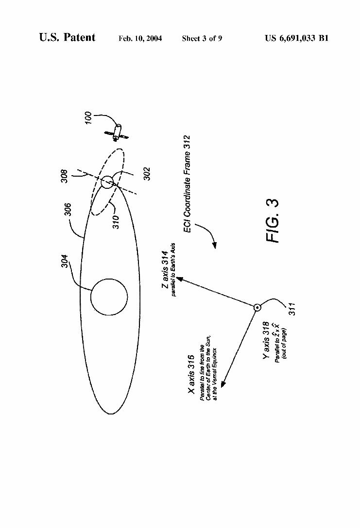
FIG. 3 is a diagram showing an Earth-Centered Inertial (ECI) reference frame;
FIG. 4 is a diagram showing a reference frame for a typical star sensor;
FIG. 5 is a flow chart presenting illustrative method steps used to practice the present invention; and
FIGS. 6A and 6B are diagrams showing one embodiment of the reference frame selected for determining the misalign- ment of the star tracker assembly;
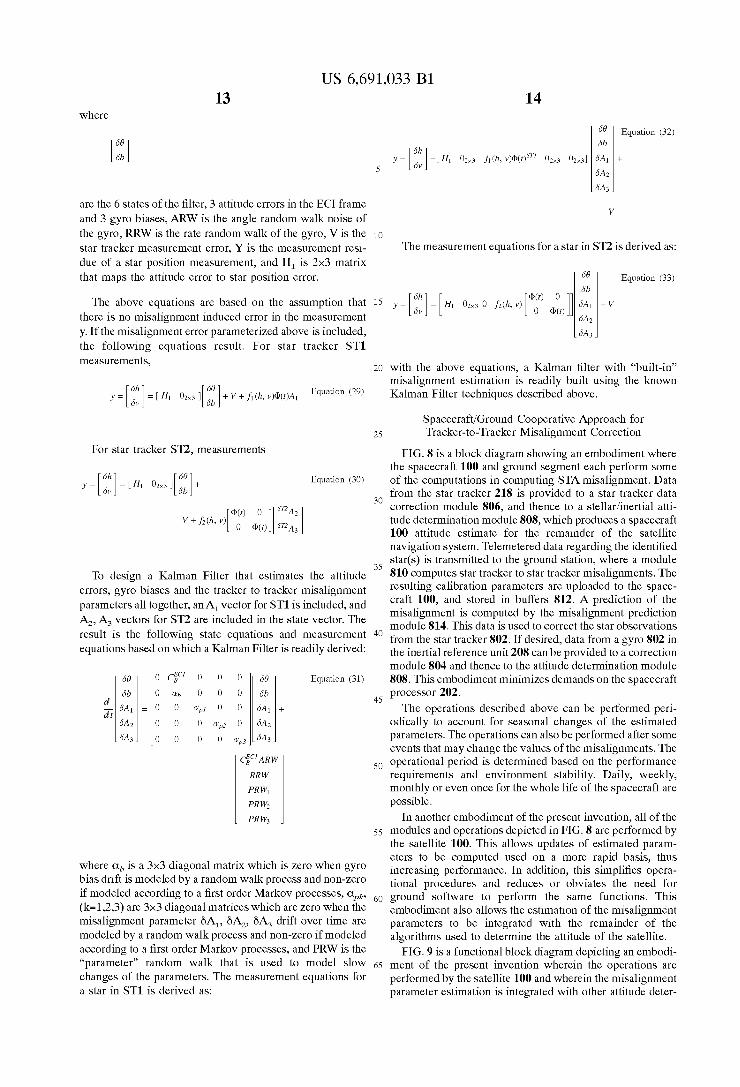
FIG. 7 is a block diagram of a generic Kalman filter; FIG. 8 is a block diagram showing an embodiment of the
present invention in which at least some of the computations performed to determine calibration parameters are per- formed at a ground station; and
FIG. 9 is a block diagram showing an embodiment of the present invention in which the calibration parameters are performed on-board the satellite, and are integrated with stellariinertial attitude estimation system.
DETAILED DESCRIPTION OF PREFERRED EMBODIMENTS
In the following description, reference is made to the accompanying drawings which form a part hereof, and which is shown, by way of illustration, several embodiments of the present invention. It is understood that other embodi- ments may be utilized and structural changes may be made without departing from the scope of the present invention.
FIG. 1 illustrates a three-axis stabilized satellite or space- craft 100. The spacecraft 100 is preferably situated in a stationary orbit about the Earth. The satellite 100 has a main body 102, a pair of solar panels 104, a pair of high gain narrow beam antennas 106, and a telemetry and command omnidirectional antenna 108 which is aimed at a control ground station. The satellite 100 may also include one or more sensors 110 to measure the attitude of the satellite 100. These sensors may include sun sensors, earth sensors, and star sensors. Since the solar panels are often referred to by the designations “North” and “South”, the solar panels in FIG. 1 are referred to by the numerals 104N and 104s for the “North” and “South” solar panels, respectively.
FIG. 1 also illustrates the spacecraft 100 reference frame 112. This reference frame 112 is a body-fixed, non-inertial frame defined so that an object attached to the spacecraft body 102 has an essentially constant position with respect to that frame, regardless of how its position changes in other reference frames to another reference frame such as an earth-centered inertial (ECI) reference frame. The attitude is the orientation of the body-fixed frame with respect to an inertial frame.
The Y (pitch) axis is chosen to be parallel to the solar panel 104 longitudinal axis. The solar panels 104 are designed to rotate about that axis, but the axis itself is typically fixed in the body frame. The X and Z axes are normal to faces of the spacecraft body 102. The X axis, which typically “points” in the direction of spacecraft 100 motion, is the roll axis and the Z axis, which typically “points” to Earth, is the yaw axis. As this frame is body- fixed, even if the spacecraft 100 is at an orientation where the X and Z axes are not pointing in the direction of motion, and Earth 302, respectively, the axes do not change. They are still defined as in FIG. 1.
S
10
1s
20
2s
30
3s
40
4s
so
5s
60
65
4 FIG. 2 is a diagram depicting the functional architecture
of a representative attitude control system. Control of the spacecraft is provided by a computer or spacecraft control processor (SCP) 202. The SCP performs a number of functions which may include post ejection sequencing, transfer orbit processing, acquisition control, stationkeeping control, normal mode control, mechanisms control, fault protection, and spacecraft systems support, among others. The post ejection sequencing could include initializing to ascent mode and thruster active nutation control (TANC). The transfer orbit processing could include attitude data processing, thruster pulse firing, perigee assist maneuvers, and liquid apogee motor (LAM) thruster firing. The acqui- sition control could include idle mode sequencing, sun searchiacquisition, and Earth searchiacquisition. The sta- tionkeeping control could include auto mode sequencing, gyro calibration, stationkeeping attitude control and transi- tion to normal. The normal mode control could include attitude estimation, attitude and solar array steering, momen- tum bias control, magnetic torquing, and thruster momentum dumping (H-dumping). The mechanism mode control could include solar panel control and reflector positioning control. The spacecraft control systems support could include track- ing and command processing, battery charge management and pressure transducer processing.
Input to the spacecraft control processor 202 may come from any combination of a number of spacecraft compo- nents and subsystems, such as a transfer orbit sun sensor 204, an acquisition sun sensor 206, an inertial reference unit 208, a transfer orbit Earth sensor 210, an operational orbit Earth sensor 212, a normal mode wide angle sun sensor 214, a magnetometer 216, and one or more star sensors 218.
The SCP 202 generates control signal commands 220 that are directed to a command decoder unit 222. The command decoder unit operates the load shedding and battery charging systems 224. The command decoder unit also sends signals to the magnetic torque control unit (MTCU) 226 and the torque coil 228.
The SCP 202 also sends control commands 230 to the thruster valve driver unit 232 which in turn controls the liquid apogee motor (LAM) thrusters 234 and the attitude control thrusters 236.
Wheel torque commands 262 are generated by the SCP 202 and are communicated to the wheel speed electronics 238 and 240. These effect changes in the wheel speeds for wheels in momentum wheel assemblies 242 and 244, respectively. The speed of the wheels is also measured and fed back to the SCP 202 by feedback control signal 264.
The spacecraft control processor also sends jackscrew drive signals 266 to the momentum wheel assemblies 243 and 244. These signals control the operation of the jack- screws individually and thus the amount of tilt of the momentum wheels. The position of the jackscrews is then fed back through command signal 268 to the spacecraft control processor 202. The signals 268 are also sent to the telemetry encoder unit 258 and in turn to the ground station 260.
The spacecraft control processor also sends command signals 254 to the telemetry encoder unit 258 that in turn sends feedback signals 256 to the SCP 202. This feedback loop, as with the other feedback loops to the SCP 202 described earlier, assist in the overall control of the space- craft. The SCP 202 communicates with the telemetry encoder unit 258, which receives the signals from various spacecraft components and subsystems indicating current operating conditions, and then relays them to the ground

US 6,691,033 B3 5
station 260. Data received may also be received by the telemetry encoder unit 258 from the ground station 260 and passed to the SCP 202.
The wheel drive electronics 238,240 receive signals from the SCP 202 and control the rotational speed of the momen- tum wheels. The jackscrew drive signals 266 adjust the orientation of the angular momentum vector of the momen- tum wheels. This accommodates varying degrees of attitude steering agility and accommodates movement of the space- craft as required.
The use of reaction wheels or equivalent internal torquers to control a momentum bias stabilized spacecraft allows inversion about yaw of the attitude at will without change to the attitude control. In this sense, the canting of the momen- tum wheel is entirely equivalent to the use of reaction wheels.
Other spacecraft employing external torquers, chemical or electric thrusters, magnetic torquers, solar pressure, etc. cannot be inverted without changing the control or reversing the wheel spin direction. This includes momentum bias spacecraft that attempt to maintain the spacecraft body fixed and steer payload elements with payload gimbals.
The SCP 202 may include or have access to memory 270, such as a random access memory (RAM). Generally, the SCP 202 operates under control of an operating system 272 stored in the memory 270, and interfaces with the other system components to accept inputs and generate outputs, including commands. Applications running in the SCP 202 access and manipulate data stored in the memory 270. The spacecraft 100 may also comprise an external communica- tion device such as a satellite link for communicating with other computers at, for example, a ground station. If necessary, operation instructions for new applications can be uploaded from ground stations.
In one embodiment, instructions implementing the oper- ating system 272, application programs, and other modules are tangibly embodied in a computer-readable medium, e.g., data storage device, which could include a RAM, EEPROM, or other memory device. Further, the operating system 272 and the computer program are comprised of instructions which, when read and executed by the SCP 202, causes the spacecraft processor 202 to perform the steps necessary to implement and/or use the present invention. Computer pro- gram and/or operating instructions may also be tangibly embodied in memory 270 and/or data communications devices (e.g. other devices in the spacecraft 100 or on the ground), thereby making a computer program product or article of manufacture according to the invention. As such, the terms “program storage device,” “article of manufac- ture” and “computer program product” as used herein are intended to encompass a computer program accessible from any computer readable device or media.
Reference Frames Used in Attitude Determination Spacecraft attitude is the orientation of the spacecraft 100
with respect to some known reference frame. One possible reference frame is fixed with respect to both
the Earth 302 and the Sun 304. This reference frame is useful because the satellite’s mission is usually concerned prima- rily with pointing antennae at the Earth 302, and directing the solar panels 104 to at the Sun 304. Attitude determina- tion in such a frame requires finding where the centers of the Sun and Earth are with respect to the spacecraft.
One problem with using such a reference frame is that it is hard to determine exactly where the center of the Sun and/or Earth is with respect to a spacecraft at any given time.
6 Sun sensors 214 and Earth sensors 212, which are used for such purposes, give errors of approximately 0.02 degree and 0.05 degree, respectively. Hence, attitude estimates based on such readings will be off by 0.02 degree, or more. In many
5 cases, this accuracy is insufficient to meet current satellite mission requirements.
The attitude of the spacecraft can also be expressed in accordance with an inertial reference frame. The attitude of
10 the spacecraft 100 in an inertial reference frame can be determined directly from the observation of inertially fixed objects, such as stars, instead of moving objects such as the Sun and Earth. Because a typical star sensor 218 is accurate to about 15 arc-seconds (0.004 degree), attitude estimates
15 formulated using star trackers are more accurate than esti- mates formulated using conventional Sun and Earth sensors 214 and 212. Once the spacecraft attitude is known in the inertial reference frame, the orbital information of the spacecraft, the Sun, and the Earth can be used to compute the
2o angular positions of the Sun and the Earth relative to the satellite 100.
FIG. 3 is a diagram showing an Earth-Centered Inertial (ECI) reference frame 312 used for one embodiment of the
25 method described herein. The origin 310 of the ECI refer- ence frame 312 (where the X axis 316, the Y axis 318, and the Z axis 314 meet) is defined at the current position of the satellite 100. The position of the origin changes in time, but the orientation of axes 314-318 do not. The Z-axis 314 is
30 taken to be parallel to Earth’s spin axis 308, pointing North. The X and Y axes are perpendicular to the Z-axis 314, and are therefore parallel to vectors lying in Earth’s 302 equa- torial plane 311. The X-axis 316 is chosen to be parallel to a line lying in the plane of the ecliptic 306 (the plane containing the orbits of the planets), as well as the equatorial plane. The X axis 316 can be defined as the line from the center of the Earth 302 to the Sun 304 at the vernal equinox (March 21). The stars’ positions in this frame are referenced
40 by unit vectors pointing from the spacecraft 100 to the star. Throughout this disclosure, all vectors are taken to be of unit length, unless specified otherwise. The star positions are nearly fixed in the ECI reference frame 312.
Since the origin of the frame is at the spacecraft position, 45 spacecraft motion affects ECI position of the stars. However,
in practice, the stars are far enough away so that the unit vectors remain essentially constant as the spacecraft moves. The above definition of the ECI reference frame 312 also ignores the fact that the orientation of Earth’s axis changes over time. This is because the Earth precession period is about 26,000 years. Therefore, the axes 314-318 of the ECI reference frame 312 is often specified with respect to a particular time (e.g., noon, Jan. 1, 2000).
3s
55 Star Tracker Reference Frames
FIG. 4 is a diagram showing a reference frame for a typical star sensor 218 and sun shade 402. In most cases, star sensors 218 (hereinafter alternatively referred to as star trackers) make star observations with respect to a body-fixed reference frame pertaining to the star tracker only.
The star tracker 218 reports stars 410 at horizontal and vertical Cartesian coordinate positions (H,, V,) in the star
65 tracker’s field-of-view (FOV). These (H,, V,) positions may be converted to a unit vector expressed in the star tracker’s reference frame as follows:
60

sT'U~ ( k )
sT'U1(l, k )
sT'U1(2, k )
sT'U1(3, k )
US 6,691,033 B1 7 8
determination (ATD) body frame. The ATD body frame can then be defined to be a fixed rotation away from the STA reference frame. As can be seen, in this definition of STA frame and ATD body frame, the boresight axis of the
5 primary star tracker 602 and the plane 612 spanned by the boresight axis of the primary star tracker 602 and the boresight axis of the secondary star tracker 608 provide an error free datum for further computations,
Returning to FIG. 5, the misalignment of at least one star tracker is determined as a rotation of the reference frame defined above. This is depicted in block 504. In one embodiment, the determination of the misalignments depicted in block 504 includes the steps of determining a first misalignment component as a boresight angular rotation angle error sT160, 620 about the Z axis 606, determining a second misalignment component as a separation angle error 6y 622 between the boresight of the primary star tracker 602 and the boresight of the secondary star tracker 608 and a third misalignment component as a boresight rotation angle error '"68,624 about the boresight axis (z) of the secondary
The star position errors due to the 3 misalignment param-
H l ( k ) Equation (1) -
[VI:"']
1
J1 + H:(k) + V:(k)
wherein in the notation STIUlm(k), ST1 indicates that the unit vector is represented in the coordinate frame (h, V, Z) of a first star tracker ST1, the "1" subscript indicates that the unit vector is for a star observed by the first star tracker ST1, the "m" indicates that the value is a measured value, and the "k" in the parentheses indicates that the unit vector refers to star "k" observed by star tracker ST1.
Further, the measurements can be derived from the unit vector as follows:
sT'Ul( l , k ) Equations (2A) (2B) H l ( k ) = ~
sT'U1(3, k )
2o tracker 618. sT'U~ (2, k ) V1(k) = ~
sT'U1(3, k )
eters are provided below. The star tracker 218 may also report the stars' magnitudes, in addition to their positions.
If the star tracker 218 is rigidly attached to the spacecraft body 102, the star tracker reference frame 412 is another type of spacecraft body-fixed frame. Neglecting launch vibration, and or cumulative thermal deformation, a time- invariant transformation between the spacecraft body-fixed 3o frame and the star tracker reference frame 412, can be defined. This transformation is typically expressed in terms of a direction cosine matrix.
2s
Direction Cosine Computation
Alignment data provides apriori knowledge of the direc- tional cosine matrix. Specifically, (')CBST1 represents the apriori knowledge of the directional cosine matrix describ-
3s
ing the relationship between the spacecraft 100 body and star tracker ST1, and (')CBST1 represents the apriori knowl- edge of the directional cosine matrix describing the rela- tionship between the spacecraft 100 body and star tracker ST2. With this information, an initial apriori knowledge of a transformation between the star trackers' reference frames can be defined as:
~ , , ~ " _ ( O ) ~ , ~ " ( ( O ) ~ , ~ ~ ~ ) T , Equation (3)
STA Reference Frame and Parameterization of Star- Tracker Misalignments
FIG. 5 is a flow chart presenting exemplary method steps used to practice one embodiment of the present invention. First, a reference frame is defined for the star tracker assembly (STA), as shown in block 502.
FIGS. 6Aand 6B are diagrams showing the STAreference frame 614. The reference frame is defined according to a boresight V,, 602 of a primary star tracker 604 (axis Z 606) and a boresight V,, 608 of a secondary star tracker 610 selected from at least two secondary star trackers. A datum for the STA reference frame is at least partially defined by the boresight of the primary star tracker 602 and a plane 612 spanned by the boresight of the primary star tracker 602 and the boresight of the secondary star tracker 608. The Y axis 616 is orthogonal to the ulane 612 suanned bv the boresights
40
4s
so
5s
60
For the primary tracker, we have
For the second tracker. we have
Misalignment Component Estimation The value of these components can be determined as
follows. First, apriori knowledge of the STA frame can be used to derive the following three matrices:
(o)C,STAA,(O)CsTAsT1~)csTAs" Equation (4)
An initial estimate of the primary star tracker boresight rotation angle ST%, 626 with respect to the STA reference frame is determined. This is accomplished by applying the relationship (')CSTAsT1 to apriori knowledge of the primary star tracker boresight rotation angle (typically obtained during ground alignment). The misalignment component sT160z to be estimated is an error of this angle. An initial estimate of the secondary star tracker boresight rotation angle '"0, can be similarly determined by applying the relationship (')C,,'" to apriori knowledge of the second- ary star tracker boresight rotation angle. The misalignment component '"60, to be estimated is an error of this angle.
Apair of stars observed by the primary and secondary star trackers are then associated with stars in a star catalog. Typically, the stars in the star catalog are presented in the ECI coordinate frame. An ECI unit vector for each star is then computed. For a pair of stars i and k, the unit vectors are expressed as:
zc'Ul(k) and zc'U2(j). Equation (5) I I
of the primary and secondary star trackers 602, 608, and the 65 X axis 618 is the cross product of the Y axis 616 and the Z axis 606. This reference frame is used to define an attitude
Unit vectors derived from measurements from each star observed by the primary star sensor 610 are transformed into the second star sensor 604's coordinate frame as follows:

US 6,691,033 B3 10
Further, unit vectors derived from measurements from each star observed by the secondary star sensor 604 are transformed to the first star sensor's 610 coordinate frame as follows:
TT,"(k)=(o)c,,~n ,RU,"(k) Equation (7)
Then, for each pair of stars (kj), the following derived measurements are formed.
y ( ~ j ) = < s ~ U l m ( k ) ~ ~ U Z m ( j ) > - < Z C ' U l ( k ) , Z C ' U Z ( j ) > Equation (8)
This determines the difference between the ideal inner product of the measured star positions and the star positions in the star catalog. Next, coefficient matrices are formed. For each star observed by the primary star sensor 610, the following is formed for each star:
Further, for each star observed by the secondary star sensor 604, the following is formed
Equation (10)
wherein the boresight rotation angle is computed as described above. Next, the following 4x3 matrix is formed for each pair of stars:
Equation (1 1)
As a result, for each pair of star measurements, the following measurement equation is obtained:
An estimate of the parameters:
Equation (13)
can now be obtained using least squared estimation or other techniques.
Corrected directional cosine matrices can be derived as follows:
(1 )c , ,~~1=R, (~~6B~) (o )c ,~A~~l
( 1 ) C , , S " = R , ( , R 6 B , + S R B = ) R ~ ( 6 ~ ~ = ( - , ~ ~ ~ ~ ~ ~ ~ ~ A ) and (14B)
As a result, an updated estimate of the directional cosine matrices (indicated by the (1) superscript), can be obtained from the initial (apriori) directional cosine matrices
S
10
1s
20
2s
30
3s
40
4s
so
5s
60
65
(indicated by the (0) superscript). If further iteration is required, the same relationship is used, wherein the updated estimate (1) is substituted for the apriori information (2), and the application of the equation results in an estimate (3).
In addition, the 3 parameters described above in Equation (13) typically change with temperature. And it is often necessary to further represent these parameters by some base functions such as sine and cosine functions that characterize the diurnal errors.
For parameter ~= '~ '68 , 6y, ST268,
Equation (15)
where s are integers, AJs) are the coefficients and $(t,s) are base functions. An example of the base functions are cosine and sine functions, i.e.
4(r, s) = cos((s - 1)2irf) or Equations (16A) and (16B)
where T is the satellite 100 orbit period. In such cases, the measurement equation becomes
where Al, A2 and A3 are the coefficient vectors for the 3 parameters
ST168, 6y, S"68, Using the above equations, a least square estimator for the
misalignment modeling parameters can be constructed. The estimator may be a batch estimator, which is suitable where some or all of the computations are performed by a ground station instead or in addition to the satellite 100, or a recursive estimator, which is typically implemented solely in the satellite 100.
Kalman Filter Background
FIG. 7 illustrates a process that is based on an estimate update equation
.*(t,+)=.*(t,~)+k(t,)o.(t,)-Y *K)l Equation (18)
in which a state prediction x*(t,-) is updated by a portion k(t,) of a residue which is the difference between a mea- surement y(t,) and a measurement prediction y*(t,-) to thereby form an estimate x*(t,'). The portion k(t,) is typi- cally referred to as the Kalman gain and is calculated as

11 US 6,691,033 B1
12 When these replacements are made in equation (2), the
Equation (19) calculation of gain becomes
K(t,)=P(t,~)HT(t,){H(t,)P(t,3HT(t,)+R(t,)l~ Equation (24) 5
in which a,*’(t,-) is the estimate variance (i% uncertainty of the estimate) and 0,’ is the measurement variance 6.e. the uncertainty of the measurement).
As the process is recursively continued, the estimate variance is reduced below the measurement variance so that i o the gain k(t,) declines to a value much less than one. It is
in which the error covariance P(t,) is appropriately modified by the measurement converter H(t,) and its transform HT(t,). The extrapolation process of Equation (24) is performed by the gain calculation of block 762,
The error covariance P(t,) is updated between measure-
apparent from equation (18) therefore, that a large portion of the residue {y(t,)-y*(t,-)} is initially used to update the state prediction x*(t,-) into the updated estimate X*(t,+), but this portion decreases as the process continues (i.e. the IS H(t,). weight given to new measurements are successively reduced). In particular, the estimate variance is reduced at
merits in an update 764 wherein the estimate variance ax*2(tfi> Of equation (20) has been rep1aced by the error covariance P(tn) as modified by the measurement converter
the error covariance p(t,> is Processed as
each measurement y(t,) in accordance with P ( t ~ ) = { I - K ( t ~ ) H ( t ) } P ( t ~ ~ ) Equation (25)
ox. *( t~+)=( l -k( t~) )o~. ’ ( t , - ) Equation (20) 2o The updated error covariance is then passed through a delay 765 and extrapolated over time to form an error covariance P(t,-). As shown in extrapolation block 766, this extrapolation is processed as
These processes are expressed in a more general matrix form in FIG. 7 where they are partitioned into an estimator 742 and a gain calculator 744 that supplies gain K(t,) to a multiplier 746 of the estimator. The estimator 742 receives a measurement Y(t,) at an input port 748 and provides an 25 estimate X*(t,+) for a time just after the measurement to an and is effected with the state transition @(t,,t,-l) and its output port 750. From this estimate matrix, a state prediction transform. In addition, plant or process noise, which X*(t,-) is formed for a time just before the next measure- ment and this state prediction is provided to a Summer 752, includes modeling errors as well as actual noise and system
Because the state of the system typically varies dynami- 3o disturbances, is summarized in a process-noise covariance cally between measurements, the estimate X*(t,+) must be Q(t,- 1)
extrapolated over time to form the state prediction X*(t,-). 744 the error This extrapolation is accomplished by passing the estimate covariance P(tn> in update block 764, delays it in delay 765, X*(t,+) through a delay 754 and multiplying it by a state and extrapolates it in extrapolation block 66 to generate the transition 756 which contains extrapolation information in 35 error covariance p(t,->. The updated, delayed, and extraPo- the form of a state transition @(t,,t,-,). The state prediction lated error COvariance in extrapolation block 766 is then Xyt,-) is also multiplied by a measurement converter 758 combined with the measurement-noise covariance R(t,) in to form a measurement predictionY*(t,-) which is provided the gain Calculation block 762 to Calculate a gain K(t,) to a differencer 760 where it is differenced with the mea- which is provided to the estimator 722 for processing the surement Y(t,). The measurement converter 758 H(t,) con- 40 Current measurement Y(tn) at the input Port 750. The update &ions the state prediction x*(t,-) so that its elements block 764 indicates that the error covariance P(t,) will correspond to those of the measurement Y(t,) and can be reduce Over time to properly differenced with it.
The differencer 760, therefore, generates a residue Y(t,)- H(t,)Y*(t,-) which is then multiplied by multiplier 746 to 45 form a correction K(t,){Y(t,)-H(t,)Y(t,-} that will be used to update the estimate. The updating is performed in the Summer 752 where the correction is summed with the state prediction X*(t,-) to generate the updated estimate
P(t~-)=~.(t~,t~~i)P(t~+)~T(t~,t~~i)+Q(t~~i) Equation (26)
In summarY, the gain
state Operational
Misalignment Estimation Using Gyro and Star Tracker Data
Both gyro and star-tracker data can be used to estimate STAmisalignment. This algorithm produces both the space- craft attitude and the tracker-to-tracker misalignment esti-
so mates and any other estimates (such as gyro bias) typically estimated by the attitude determination Kalman Filter.
To begin, consider a Kalman Filter design without mis- alignment. For example, a simple six-state Kalman Filter that estimates the attitude error and gyro bias based on the
X*(t,+)=X* (t,~)K(t,){Y(t,)-H(t,)Y(t,l Equation (21)
at the output port 750. The gain calculator 744 performs similar updating and
extrapolation processes for the gain K(t,) The estimate variance a,,’(t,-) and the measurement variance a,’ of 55 following state equations: Equation (19) are respectively replaced by an error covari- ance P(t,) and a measurement noise covariance R(t,) which 0 c y C&,ARW Equation (27) are measures of estimate error and of measurement error. In g[:i]=[O 0 ][:i]+[ RRW ] particular, the error covariance P(t,) is defined as
60 P(tJ=E{(X(t,)-X* (L))(X* (L-x(L))T} Equation (22)
and the following measurement equation in which E{*} is the expected value of the argument and refers to the transpose operation. If the difference between a sate parameter and its estimate is referred to as estimation error and shortened to “err”, then equation (22) becomes
6e Equation (28) 65
P(t,)=E(err(X)err(X)‘} Equation (23)
US 6,691,033 B3
~
6b
6A1
6Az
6A3 ~
13
Equation (32)
+
14
y = [ :: 1 = [ H I 0zx3 0 f d h , v) [@F @yr) 11 The above equations are based on the assumption that 15 there is no misalignment induced error in the measurement y. If the misalignment error parameterized above is included,
where
6b
6’1
6A z
~ 6A3
are the 6 states of the filter, 3 attitude errors in the ECI frame and 3 gyro biases, ARW is the angle random walk noise of the gyro, RRW is the rate random walk of the gyro, V is the 10
V
-_ -_ star tracker measurement error, Y is the measurement resi- due of a star position measurement, and H, is 2x3 matrix
The measurement equations for a star in ST2 is derived as:
that maps the attitude error to star position error. 1 Equation (33)
+ V
measurements, 20 with the above equations, a Kalman filter with “built-in”
misalignment estimation is readily built using the known Kalman Filter techniques described above. 6h
= [ 6 v ] = [ H~ oZx3 I [ :;] + v + f l ( h , ”)@([)Al Equation (29)
SpacecraftiGround Cooperative Approach for 2s Tracker-to-Tracker Misalignment Correction
FIG. 8 is a block diagram showing an embodiment where the spacecraft 100 and ground segment each perform some of the computations in computing STA misalignment. Data from the star tracker 218 is provided to a star tracker data correction module 806, and thence to a stellariinertial atti- tude determination module 808, which produces a spacecraft 100 attitude estimate for the remainder of the satellite navigation system. Telemetered data regarding the identified star(s) is transmitted to the ground station, where a module 810 computes star tracker to star tracker misalignments. The
craft 1o02 and in buffers ‘12. A prediction Of the misalignment is computed by the misalignment prediction module 814. This data is used to correct the star observations
state equations and measurement 40 from the star tracker 802, If desired, data from a gyro 802 in the inertial reference unit 208 can be Drovided to a correction
For star tracker S n , measurements
y = [ 6h 6”] = [HI o h 3 I [ :;I+ Equation (30)
30
V + f 2 ( h r v)[@@) ] I S n A z ] 0 @ ( f ) snA3
3s T~ design a ~~l~~~ Filter that estimates the attitude
parameters all together, an A, vector for ST1 is included, and A2, A3 vectors for ST2 are included in the state vector. The
equations based on which a Kalman Filter is readily derived:
errors, gyro biases and the tracker to tracker misalignment parameters are up1oaded to the space-
is the
module 804 and thence to the attitude determination module 808. This embodiment minimizes demands on the spacecraft processor 202.
The operations described above can be performed peri- odically to account for seasonal changes of the estimated parameters. The operations can also be performed after some events that may change the values of the misalignments. The
so operational period is determined based on the performance requirements and environment stability. Daily, weekly, monthly or even once for the whole life of the spacecraft are possible.
In another embodiment of the present invention, all of the 5s modules and operations depicted in FIG. 8 are performed by
the satellite 100. This allows updates of estimated param-
Equation (31)
4s
eters to be computed used on a more rapid basis, thus
bias drift is modeled by a random walk process and non-zero tional procedures and reduces or obviates the need for if modeled according to a first order Markov Processes, 60 ground software to perform the same functions. This (k=1,2,3) are 3x3 diagonal matrices which are zero when the embodiment also allows the estimation of the misalignment misalignment Parameter 6A,, 6 4 , 6A3 drift Over time are parameters to be integrated with the remainder of the modeled by a random walk process and non-zero if modeled algorithms used to determine the attitude of the satellite. according to a first order Markov processes, and PRW is the FIG, 9 is a functional block diagram depicting an embodi- ‘‘Parameter’’ random walk that is used to model Slow 65 ment of the present invention wherein the operations are changes of the parameters. The measurement equations for performed by the satellite 100 and wherein the misalignment a star in ST1 is derived as: parameter estimation is integrated with other attitude deter-
where ab is a 3x3 matrix which is zero when gyro increasing performance, In addition, this simplifies opera-

US 6,691,033 B1 15 16
mination functions and implemented in a Kalman filter 904. Here, star tracker 218 data and gyro 802 data are corrected using estimates of the gyro errors and star tracker misalign- ment errors generated by the Kalman filter 904. Hence, star tracker misalignment computations are used not only to correct the star tracker data, but in the algorithms used in the attitude determination module 902 as well.
determining a second misalignment as the error of a separation angle (6y) between the boresight of the primary star tracker and the boresight of the second star tracker; and
determining a third misalignment as the error of a bore- sight rotation angle (""68,) about the boresight of the second star-tracker.
5
Conclusion This concludes the description of the preferred embodi-
ments of the present invention. In summary, the present lo invention describes a method, apparatus, for determining the attitude of the misalignment of a star tracker assembly.
The foregoing description of the preferred embodiment of the invention has been presented for the purposes of illus- tration and description. For such exemplary purposes, the 15 methods and systems presented herein have been described with respect to a the tracking of single stars from each star tracker. Typically, however, the foregoing operations are completed for multiple star measurements from each star tracker, and such measurements are taken and accumulated 20 across the sky to include hundreds or thousands of mea- surements from each star tracker.
As such, the foregoing is not intended to be exhaustive or to limit the invention to the precise form disclosed. Many modifications and variations are possible in light of the 25 above teaching. It is intended that the scope of the invention be limited not by this detailed description, but rather by the claims appended hereto. The above specification, examples and data provide a complete description of the manufacture and use of the composition of the invention. Since many 3o embodiments of the invention can be made without depart- ing from the spirit and scope of the invention, the invention resides in the claims hereinafter appended.
What is claimed is: 1. A method of determining a misalignment at least one 35
star tracker of star tracker assembly comprising a primary star tracker and second star tracker, comprising the steps of
defining a reference frame for the star tracker assembly according to a boresight of the primary star tracker and a boresight of a second star tracker, wherein the bore- 40 sight of the primary star tracker and a plane spanned by the boresight of the primary star tracker and the bore- sight of the second star tracker at least partially define a datum for the reference frame for the star tracker
determining the misalignment of the at least one star tracker as a rotation of the defined reference frame, wherein the step of defining the reference frame for the star tracker assembly comprises the steps of defining a first axis (z) of a reference frame for the star 50
tracker such that the boresight of the primary star tracker is aligned with a first (z) axis;
defining a second axis (y) the reference frame orthogo- nal to the first axis (z) wherein the second axis (y) is orthogonal to a plane spanned by the boresight of the 5s primary star tracker and the boresight of the second star tracker; and
defining a third axis (x) of the reference frame accord- ing to the cross product of the first axis of the reference frame and the second axis of the reference 60 frame.
2. The method of claim 1, wherein the step of determining the misalignment of the at least one star tracker comprises the steps of
determining a first misalignment as the error of a bore- 65 sight angular rotation angle (sT168z) about the first axis
assembly; and 4s
( 4 ;
3. The method of claim 1, wherein the step of determining the misalignment of the at least one star tracker as a rotation of the defined reference frame comprises the steps of
determining a first misalignment as an angular rotation angle error about the boresight of the primary star tracker;
determining a second misalignment as a separation angle error between the boresight of the primary star tracker and the boresight of the second star tracker; and
determining a third misalignment as an angular rotation angle error about the boresight of the second star tracker.
4. The method of claim 3, wherein the first misalignment, the second misalignment, and the third misalignment include time-varying errors.
5 . The method of claim 1, wherein the misalignment of the star tracker is estimated according to an estimator using a measurement equation described by:
wherein y(j,k) represents a measurement derived from of a pair of stars denoted by k and j by taking a difference between the inner products of the measured star unit vector and the unit vector as determined from a star catalogue, and v(kj) represents measurement noise for the pair of stars denoted by k and j, wherein sT168,, represents the first misalignment angular error, 6y rep- resents the second misalignment angular error, and
68, represents the third misalignment angular error; and wherein ST2
wherein V(k) is the measured position of stark by the first star tracker in a first star tracker vertical axis, H(k) is the measured position of star k by the first star tracker in a first star tracker horizontal axis;
wherein
wherein V(j) is the m red position of star j by the second star tracker in a second star tracker vertical axis and H(j) is the measured position of star j in a second star tracker horizontal axis, SR8z is an apriori value for the boresight angular rotation angle about the boresight of the second star tracker;

US 6,691,033 B3 17
wherein SRU,"(l,k) is a first element of a unit vector in the second star tracker's reference frame for a position of the star k measured by the primary star tracker,
U1"(2,k) is a second element of a unit vector in the second star tracker's reference frame for the position of s the star k measured by the primary star tracker, sTIU,m ( l j ) is a first element of a unit vector in the primary star tracker's reference frame for the position of the star j measured by the second star tracker, and sT1U2m(2,j) is a second element of a unit vector in the primary star i o tracker's reference frame for the position of the star j measured by the second star tracker.
6. The method of claim 1, further comprising the steps of determining a data correction value for each of the star
trackers in the star tracker assembly from the misalign- 15 ment error; and
correcting measurements from each of the star trackers with the data correction values.
7. The method of claim 1, wherein the star tracker assembly is disposed on a satellite, and the step of deter- 2o mining the misalignment of the star tracker assembly com- prises the steps of
transmitting star tracker assembly measurements from the
estimating the misalignment of the star tracker assembly
transmitting the estimated misalignment of the star tracker
8. The method of claim 1, wherein the step of determining 3o
ST2
satellite to a ground station;
at the ground station; and
assembly to the satellite.
2s
a misalignment of the at least one star tracker as a rotation of the defined reference frame comprises the step of apply- ing the measurement to a Kalman filter, the Kalman filter is defined according to:
a state vector representing attitude errors, gyro errors, and 35 star tracker misalignment errors according to the defined reference frame;
an augmented error dynamic model including a state transition matrix, the state transition matrix comprising a matrix modeling spacecraft attitude errors and gyro 40 errors augmented with a model of star tracker misalign- ment errors wherein variation of parameters in the augmented state transition matrix are modeled by a differential equation having random inputs; and
a measurement equation and measurement matrix, the 45 measurement equation and measurement matrix com- prising a measurement equation and a measurement matrix modeling spacecraft attitude measurement errors and gyro measurement errors augmented to model star tracker measurement errors. so
9. The method of claim 8, wherein: the augmented error dynamic model is characterized in a
continuous time domain by
wherein ab, is a 3x3 diagonal matrix which is zero when gyro bias
drift is modeled by a random walk process and non- 65 zero if modeled according to a first order Markov processes;
18 apb (k=1,2,3) are 3x3 diagonal matrices which are zero
when the misalignment parameter 6A,, 6A,, 6A, drift over time are modeled by a random walk process and non-zero if modeled according to a first order Markov processes;
the 68 parameter represents spacecraft attitude errors in an inertial reference frame, the 6b parameter represents gyro biases, the 6A,, 6 4 , 6A, parameters represent coefficient vectors for the defined reference frame, C,"" represents a direction cosine matrix transforma- tion from a spacecraft body reference frame to the inertial reference frame, ARW represents an angle random walk of the gyro, RRW represents a rate random walk of the gyro, PRW,, PRW,, and PRW, represent slow changes of the parameters 6A,, 6 4 , 6A,; and
the measurement equation and measurement matrix for the primary star tracker are characterized by
and the wherein H, represents a geometric mapping from an
inertial reference frame attitude error to a star position error, 6v and 6h represents a difference between mea- sured star position and predicted star position based on known attitude knowledge,
wherein v is the measured position of a star by the first star tracker in a first star tracker vertical axis and h is the measured position of the star in a first star tracker horizontal axis; @(t) represents a matrix formed by base functions parameterizing time-varying misalign- ment parameters
and V represents primary star tracker measurement error; and
the measurement equation and measurement matrix for the secondary star tracker is
+ V

US 6,691,033 B3 19
h -cossTzezl sinsTzOz ' 5
wherein v is a measured position of a star by the second star tracker in a second star tracker vertical axis and h is the measured position of star in a second star tracker horizontal axis, sight angular rotation angle about the boresight of the second star tracker.
10. Amethod for determining a misalignment at least one star tracker of a star tracker assembly comprising a first star tracker and at least one second star tracker, comprising the steps o f
(a) measuring a position of a first star with the first star
(b) transforming the measured position of the first star in 2o
(c) measuring a position of a second star with the second
(d) transforming the measured position of the second star
(e) identifying the first star and the second star; ( f ) determining a reference position of the identified first
star and the identified second star from a star catalog; (g) computing an inner product of the measured position
of the first star and the second star and the reference 30 position of the identified first star and the identified second star, the inner product representing an error in the measured star positions; and
(h) equating the error in the measured star positions with 3s a measurement error equation having error parameters
is an apriori value for the bore- lo
tracker;
a second star tracker reference frame;
star tracker;
in a first star sensor reference frame; 2s
40
wherein ST160z, represents a first misalignment angular error about a boresight of the primary star tracker, 6y represents a second misalignment angular error as a 45 separation angle error between the boresight of the primary star tracker and a boresight of the second star tracker, and SR60z, represents the third misalignment angular error as an angular rotation angle about the
(i) solving the measurement error equation for the error
11. The method of claim 10, further comprising the steps
measuring a position of a third star with the first star ss
transforming the measured position of the third star in the
measuring a position of a fourth star with the second star 6o
transforming the measured position of the fourth star in
identifying the third star and the fourth star; determining a second reference position of the identified 65
third star and the identified fourth star from the star catalog;
boresight of the second star tracker; and so
parameters.
O f
tracker;
second star tracker reference frame;
tracker;
the first star sensor reference frame;
t
computing a second inner product of the measured posi- tion of the third star and the fourth star and the second reference position of the identified third star and the identified fourth star, the inner product representing a second error in the measured star positions;
computing a third inner product of the measured position of the first star and the fourth star and the second reference position of the identified first star and the identified fourth star, the inner product representing a third error in the measured star position; and
equating the error in the measured star positions, the second error in the measured star positions, and the third error in the measured star positions with the measurement error equation and solving the measure- ment error equation for the error parameters.
12. The method of claim 11, wherein the measurement or :quation comprises:
wherein y(j,k) represents a measurement derived from of a pair of stars denoted by k and j by taking a difference between the inner products of the measured star unit vector and the unit vector as determined from a star catalogue and v(kj) represents measurement noise for the pair of stars denoted by k and j; and wherein
wherein
wherein V(k) is the measured position of star k by the first star tracker in a first star tracker vertical axis, H(k) is the measured position of stark by the first star tracker in a first star tracker horizontal axis;
wherein
wherein V(j) is the measured position of star j by the second star tracker in a second star tracker vertical axis and H(j) is the measured position of star j in a second star tracker horizontal axis, is an apriori value for the boresight angular rotation angle about the boresight of the second star tracker;
wherein SRUl"(l,k) is a first element of a unit vector in the second star tracker's reference frame for a position of the star k measured by the primary star tracker,
U1"(2,k) is a second element of a unit vector in the second star tracker's reference frame for the position of the star k measured by the primary star tracker, ST1U2m ( l j ) is a first clement of a unit vector in the primary star tracker's reference frame for the position of the star j
ST2

US 6,691,033 B3 21
measured by the second star tracker, and sT1U2m(2,j) is the is a second element of a unit vector in the primary star tracker's reference frame for the position of the star j measured by the second star tracker.
13. The method of claim 12, further comprising the steps
determining a data correction value for each of the star trackers in the star tracker assembly from the error parameters; and
correcting measurements from each of the star trackers with the data correction values.
14. The method of claim 10, wherein: the method further comprises the step of transmitting star
tracker assembly measurements from a satellite to a ground station;
performing steps (b)-(j) to estimate the error parameters at the ground station; and
transmitting the error parameters to a satellite. 15. An apparatus for determining a misalignment at least
one star tracker of a star tracker assembly comprising a primary star tracker and at least one secondary star tracker, comprising:
a transformation module for transforming a position of a first star measured by the primary star tracker into a reference frame for a secondary star tracker and for transforming the position of a second star measured by the secondary star tracker into a reference frame for the primary star tracker;
a star catalog, including reference position for each star described therein;
a module for computing an inner product of a measured position of the first star and a measured position of the second star and a reference position of the first star and a reference position of the second star, the inner product representing an error in the measured star positions;
a processor for equating the error in the measured star positions with a measurement error equation having error parameters
O f
wherein sT160z, represents a first misalignment angular error about a boresight of the primary star tracker, 6y represents a second misalignment angular error as a separation angle error between the boresight of the primary star tracker and a boresight of the secondary star tracker, and SR60z, represents the third misalign- ment angular error as an angular rotation angle about the boresight of the secondary star tracker; for solving the measurement error equation for the error param- eters.
16. The apparatus of claim 15, wherein: the transformation module further transforms the position
of a third star measured by the primary star tracker into a reference frame for a second star tracker and trans- forms the position of a fourth star measured by the second star tracker star trackers into a reference frame for the primary star tracker;
the module further computes an second inner product of a measured position of the third star and a measured position of the fourth star and a reference position of the third star and a reference position of the fourth star,
22 the second inner product representing an second error in the measured star positions;
the module further computes a third inner product of the measured position of the first star and the measured position of the fourth star and a reference position of the first star and a reference position of the fourth star, the third inner product representing a third error in the measured star positions; and
the processor solves the measurement error equation for the error parameters using the error in the measured star positions, the second error in the measured star positions, and the third error in the measured star positions.
17. The apparatus of claim 15, wherein the measurement equation comprises:
5
lo
20
2s
30
3s
40
4s
so
5s
60
65
wherein y(j,k) represents a measurement of a pair of stars denoted by k and j and v(kj) represents measure- ment noise for the pair of stars denoted by k and j ; and wherein
wherein
wherein V(k) is the measured position of star k by the first star tracker in a first star tracker vertical axis, H(k) is the measured position of stark by the first star tracker in a first star tracker horizontal axis;
wherein
wherein V(j) is the measured position of star j by the second star tracker in a second star tracker vertical axis and H(j) is the measured position of star j in a second star tracker horizontal axis, is an apriori value for the boresight angular rotation angle about the boresight of the second star tracker;
wherein SRU,"(l,k) is a first element of a unit vector in the second star tracker's reference frame for a position of the star k measured by the primary star tracker, sT2U,"(2,k) is a second element of a unit vector in the second star tracker's reference frame for the position of the star k measured by the primary star tracker, sT1U2m ( l j ) is a first element of a unit vector in the primary star tracker's reference frame for the position of the star j measured by the second star tracker, and sT1U2m(2,j) is the second element of a unit vector in the primary star tracker's reference frame for the position of the star j measured by the second star tracker.

US 6,691,033 B3 23
18. The apparatus of claim 15, wherein the processor is disposed at a ground station.
19. An apparatus of determining a misalignment at least one star tracker of a star tracker assembly comprising a primary star tracker and at least one secondary star trackers, comprising:
means for defining a reference frame for the star tracker assembly according to a boresight of the primary star tracker and a boresight of the second star tracker, wherein the boresight of the primary star tracker and a plane spanned by the boresight of the primary star tracker and the boresight of the second star tracker at least partially define a datum for the reference frame for the star tracker assembly; and
means for determining the misalignment of the at least one star tracker as a rotation of the defined reference frame; wherein the means for defining the reference frame for the star tracker assembly comprises: means for defining a first axis (z) of a reference frame
for the star tracker such that the boresight of the primary star tracker is aligned with a first (z) axis;
means for defining a second axis (y) of the reference frame orthogonal to the first axis (z) wherein the second axis (y) is orthogonal to a plane spanned by the boresight of the primary star tracker and the boresight of the second star tracker; and
means for defining a third axis (x) of the reference frame according to the cross product of the first axis of the reference frame and the second axis of the reference frame.
20. The apparatus of claim 19, wherein the means for determining the misalignment of the at least one star tracker comprises:
means for determining a first misalignment as a boresight angular rotation angle (""6eJ about the first axis (z);
means for determining a second misalignment as a sepa- ration angle 6y between the boresight of the primary star tracker and the boresight of the second star tracker; and
means for determining a third misalignment as a boresight rotation angle ('"60,) about the boresight of the sec- ond tracker.
21. The apparatus of claim 19, wherein the means for determining the misalignment of the at least one star tracker as a rotation of the defined reference frame comprises:
means for determining a first misalignment as an angular rotation angle about the boresight of the primary star tracker;
means for determining a second misalignment as a sepa- ration angle error between the boresight of the primary star tracker and the boresight of the second star tracker; and
means for determining a third misalignment as an angular rotation angle about the boresight of the second star tracker.
22. The apparatus of claim 21, wherein the misalignment of the star tracker assembly is estimated according to an estimator based on a measurement equation:
wherein y(j,k) represents a measurement of a pair of stars denoted by k and j and v(kj) represents measurement
24 noise for the pair of stars denoted by k and j; and wherein
wherein 10
1s wherein V(k) is the measured position of star k by the first star tracker in a first star tracker vertical axis, H(k) is the measured position of stark by the first star tracker in a first star tracker horizontal axis;
wherein 20
2s wherein V(j) is the measured position of star j by the second star tracker in a second star tracker vertical axis and H(j) is the measured position of star j in a second star tracker horizontal axis, '"ez is an apriori value for the boresight angular rotation angle about the boresight of the second star tracker;
wherein SRU,"(l,k) is a first element of a unit vector in the second star tracker's reference frame for a position of the star k measured by the primary star tracker,
U1"(2,k) is a second element of a unit vector in the second star tracker's reference frame for the position of the star k measured by the primary star tracker, ST1U2m ( l j ) is a first element of a unit vector in the primary star tracker's reference frame for the position of the star measured by the second star tracker, and ST1U2m(2,j) is the second element of a unit vector in the primary star tracker's reference frame for the position of the star j measured by the second star tracker.
23. The apparatus of claim 21, wherein the first misalignment, the second misalignment, and the third mis- alignment include time-varying errors.
30
ST2 3s
40
4s
24. The apparatus of claim 19, further comprising: means for determining a data correction value for each of
the star trackers in the star tracker assembly from ate
means for correcting measurements from each of the star
25. The apparatus of claim 19, wherein the star tracker assembly is disposed on a satellite, and the means for
ss determining the misalignment of the star tracker assembly comprises:
means for transmitting star tracker assembly measure-
means for estimating the misalignment of the star tracker
means for transmitting the estimated misalignment of the
26. The apparatus of claim 19, wherein the means for determining a misalignment of the at least one star tracker as
65 a rotation of the defined reference frame comprises means for applying the measurement to a Kalman filter, the Kalman filter is defined according to:
so misalignment error; and
trackers with the data correction values.
ments from the satellite to a ground station;
assembly at the ground station; and
star tracker assembly to a satellite.
60

US 6,691,033 B1 25
a state vector representing attitude errors, gyro errors, and star tracker misalignment errors according to the defined reference frame;
an augmented error dynamic model including a stare transition matrix, the state transition matrix comprising a matrix modeling spacecraft attitude errors and gyro errors augmented with a model of star tracker misalign- ment errors wherein variation of parameters in the augmented state transition matrix are modeled by a i o differential equation having random inputs; and
a measurement equation and measurement matrix, the measurement equation and measurement matrix com- prising a measurement equation and a measurement matrix modeling spacecraft attitude measurement errors and gyro measurement errors augmented to model star tracker measurement errors.
5
27. The apparatus of claim 26, wherein: the augmented error dynamic model is characterized in a 20
continuous time domain by
30 wherein ab, is a 3x3 diagonal matrix which is zero when gyro bias
drift is modeled by a random walk process and non- zero if modeled according to a first order Markov processes;
apk, (k=1,2,3) are 3x3 diagonal matrices which are zero when the misalignment parameter 6A,, 6A,, 6A, drift over time are modeled by a random walk process and non-zero if modeled according to a first order Markov 40
processes; the 68 parameter represents spacecraft attitude errors in an
inertial reference frame, the 6b parameter represents gyro biases, the 6A,, 6 4 , 6A, parameters represent coefficient vectors for the defined reference frame, 4s C,"" represents a direction cosine matrix transfoma- tion from a spacecraft body reference frame to the inertial reference frame, ARW represents an angle random walk of the gyro, RRW represents a rate random walk of the gyro, PRW,, PRW,, and PRW, represent slow changes of the parameters 6A,, 6A,, 6A,; and
the measurement equation and measurement matrix for the primary star tracker are characterized by
3s
so
26
Y = + V
and the wherein H, represents a geometric mapping from an inertial reference frame attitude error to a star position error, 6v and 6h represents a difference between measured star position and predicted star position based on known attitude knowledge,
wherein v is the measured position of a star by the first star tracker in a first star tracker vertical axis and h is the measured position of the star in a first star tracker horizontal axis; @(t) represents a matrix formed by base functions parameterizing time-varying misalign- ment parameters
and V represents primary star tracker measurement error; and
the measurement equation and measurement matrix for the secondary star tracker is
t v
wherein
wherein v is a measured position of a star by the second star tracker in a second star tracker vertical axis and h is the measured position of star in a second star tracker horizontal axis, is an apriori value for the bore- sight angular rotation angle about the boresight of the second star tracker.
* * * * *