Embed Size (px)
Citation preview
8/7/2019 11 Ijaest Volume No 2 Issue No 1 Seismic Strengthening of Low Rise Buildings Using Brick Inserts Retrofit) 072 085
http://slidepdf.com/reader/full/11-ijaest-volume-no-2-issue-no-1-seismic-strengthening-of-low-rise-buildings 1/14
SEISMIC STRENGTHENING OF LOW RISE
BUILDINGS USING BRICK INSERTS
(RETROFIT) – EXPERIMENTAL
INVESTIGATION ON 2D & 3D RC FRAMEDSTRUCTURES
Mr.R.Suresh Babu
Research scholar – Anna University, Coimbatore
Partner – PTK Architects, Chennai
Chennai, India
Dr.R.Venkatasubramani
HOD, VLBJCET, Coimbatore
Coimbatore, India
Abstract— Several literature and research papers
were published in the topic of seismic retrofit of
existing buildings. Attention has been focused on
the existing building (designed without seismic
loads) to prevent damages during future
earthquake. A purpose of the study is to investigate
seismic retrofit using brick inserts to upgrade the
capacity of reinforce concrete frame with brick
masonry infill wall and to addresses the buildings
without following the details as stated in BIS
13920. The overall aim of study is by adding asmall brick insert in the partial infilled RC
structures, the structure could double its strength.
An experimental investigation is conducted to study
the effect of lateral behaviour of RC frames with
partial-infill masonry panels (2D & 3D) viz. one
with opening(frame 1) and other with masonry
insert in the opening(frame 2). One-third scale, two-
bay two-storey RC frame (2D & 3D) designed for
gravity loading is tested under in-plane lateral
loading for 2D RC frames and push & pull load for
3D RC frame structures. A non-linear finite elementanalysis has been carried out using Ansys – 10. The
results of experiment and analytical analysis were
only marginal variations. In both 2D & 3D analysis
of both frames, the columns in the bottom storey
sustained critical shear damage with hinges in the
column portions adjacent to the gap. The
experimental results clearly indicated that the partial
infill in RC frame leads to critical damages, which
could be reinforced with the added strength of masonry inserts. Finally it was suggested that, the
existing columns with short-column mechanismcould be strengthened with masonry inserts. By
improving building strength with the above
methods, the damage can be limited to within
repairable limits and complete collapse of the
building/loss of life can be avoided during an
earthquake. The cost effectiveness of providing
brick insert is very much cheaper than retrofit
normally adopted to strengthen the structural
elements and require simple construction method.
Keywords - Masonry Infill; Masonry Inserts;
Captive Column effect; Retrofit;
I INTRODUCTION
Everyone is aware that earthquake occurred inGujarat (Bhuj) - India in the year 2001 had severalincidents of failure or complete collapse. Majority of the failure in the buildings are predominantly due toCaptive column failure or soft storeyed building.
After the revision in IS codes for seismic forces, weare able to take care of the proposed new buildings.But even many old buildings of similar nature stillexists (built as per IS 456 detailed with SP 34) inhighly earthquake prone areas throughout thecountry. Energy dissipation of these buildings arevery poor for lateral loads mainly due to Captivecolumn failure. By providing necessary masonryinserts in the partial infill opening shall increase the
katasubr
BJCET, CoimBJC
oimbatore, Indiabatore,
[email protected] yahoo.
e
atea
de thede the
th brick ick
e buildings
stated in BIS
is by adding apartial infilled RCal inf
ld double its strength.l ts strengt .
tion is conducted to studyu tudy
ehaviour of RC frames withha h
y panels (2D & 3D) viz. oanels
me 1) and other with maand o
ening(frame 2). One-third sc. One
rey RC frame (2D & 3D) derey & 3D
oading is tested under in-ding in-
2D RC frames and pusRC f
structures. A non-lctures. -lcarried outrried o
nt andand
ns
reinforced with the addedf addery inserts. Finally it was sur u
ting columns with short-cong ns w tould be strengthened withbe strengthened
improving building strenim tr
methods, the damage
repairable limits an
building/loss of liil s l
arthquake. ThT
brick insertbr t
normallynorm
lementmen
Ke
Mr.R.Suresh Babu et al. / (IJAEST) INTERNATIONAL JOURNAL OF ADVANCED ENGINEERING SCIENCES AND TECHNOLOGIESVol No. 2, Issue No. 1, 072 - 085
ISSN: 2230-7818 @ 2011 http://www.ijaest.iserp.org. All rights Reserved. Page 72

8/7/2019 11 Ijaest Volume No 2 Issue No 1 Seismic Strengthening of Low Rise Buildings Using Brick Inserts Retrofit) 072 085
http://slidepdf.com/reader/full/11-ijaest-volume-no-2-issue-no-1-seismic-strengthening-of-low-rise-buildings 2/14
stiffness of the building and increase in energydissipation. Due to this the collapse of the buildingwill delay and the structure became more safer. Thisremedy is evaluated without major alteration tostructural elements and without affecting majorexisting functioning of the buildings.
II MATERIALS AND METHODS
A LITERATURE REVIEW
Previous experimental research on the behaviour
of brick infilled RC frames(Achintya et.al.
1991:Yaw-jeng Ciou et.al.1999: Diptesh Das et.al.
2004: Ismail et.al 2004: Marina et.al:2006 have
shown that the strudtural behaviour of the framed
masonry wall subject to in – plane monotonic
loading on partial fill masonry wall induce a short
column effect aleads to severe failures of the
column. Further experimental research of MehmatEmin Kara et.al:2006 have shown that patially
infilled non-ductile RC Frames exhibited
significantly higher ultimate strength and higher
initial stiffness than the bare frame. Prabavathy
et.al(2006) have shown that infill panels can
significantly improve the performance of RC
Frames. Alidad Hashemi et.al(2006) have shown
that infill wall changes the load path and the
distribution of forces Kasim Armagan Korkmazet.al(2007) shown that presence of nonstructural
masonry infill walls can modify the global seismicbehaviour of framed building to a larger extent.
Umarani (2008) examined the behaviour of infilled
frames (5 storey) for lateral loading. Test focused
on the increase of energy dissipation over and above
the base frames. Santiago pujol et.al(2008) shown
that masonry infill walls were effective in increase
the strength(by 100%) and stiffness (by 500%) of
the original reinforced concrete structures. Salah El
– Din Fahmy Taher et.al(2008) lower location of
infill frames yields the higher strength, stiffness and
frequency of the system
III EXPERIMENTAL & ANALYTICAL
INVESTIGATION ON 2D RC FRAME STRUCTURE
1) EXPERIMENTAL INVESTIGATION
A) Modelling of Frames:
A structure representing a multi-storeyed frame
system is analysed and designed. The structure is
modeled for experimental investigation by scaling
down the geometric properties of the prototype
using the laws of Geometric similitude.
B) Details of Test Frame
Test models was fabricated to 1:3 reduced scalefollowing the laws of similitude by scaling down
the geometric and material properties of the
prototype for Frame (1) and Frame (2)(Ref. Fig.1).
Figure.1 Geometry of the frame model
C) Testing Procedure :Lumped mass distribution was
calculated and lateral loads were distributed as 80%for top storey & 20% for bottom storey. All appliedlateral loads were divided accordingly. Frame (1)was tested of first increments of 10 kN base shearfor each cycle and released to zero after each cycle.The deflections at all storey levels were measured ateach increment and decrement of the load. Theformation and propagation of cracks, hingeformation and failure pattern were recorded. Thisprocedure was repeated for frame (2) with masonryinsert.
D) Results:
The results of various parameters like load Vs.
deflection, stiffness degradation and ductility factor
were considered for study of the captive column
behaviour of the frame
i) Loading And Load-Deflection Behaviour(P- ∆ ):
The frame was subjected to unidirectional
lateral loading. The load was applied in increment
of 10 kN base shear for each cycle and released to
zero after each cycle. The deflections at all storey
levels were measured using LVDT at each
increment or decrement of load. The ultimate base
shear of 73 KN was reached in the Eighth cycle of
an
RCR
shownown
and thee
an Korkmazof nonstructural
the global seismice gg to a larger extent.larger e
the behaviour of infilledinfilled
teral loading. Test focusede f ed
rgy dissipation over and abovrgy d
antiago pujol et.al(2008) shoo pu
fill walls were effective in inere e
y 100%) and stiffness (bytiffnes
al reinforced concrete structurl rein struct
hmy Taher et.al(2008) lowTah w
yields the higher strelds the stre
e systemstem
ENTATA
2
Figure.1 Geometry of the fra
) Testing Procedure : s ting Procedure :Lumped massLu m
alculated and lateral loaa for top storey & 20% f lateral loads were de s rewas tested of firsa efor each cyclef le
he deflectiheach incrach c
formata forp
Mr.R.Suresh Babu et al. / (IJAEST) INTERNATIONAL JOURNAL OF ADVANCED ENGINEERING SCIENCES AND TECHNOLOGIESVol No. 2, Issue No. 1, 072 - 085
ISSN: 2230-7818 @ 2011 http://www.ijaest.iserp.org. All rights Reserved. Page 73
8/7/2019 11 Ijaest Volume No 2 Issue No 1 Seismic Strengthening of Low Rise Buildings Using Brick Inserts Retrofit) 072 085
http://slidepdf.com/reader/full/11-ijaest-volume-no-2-issue-no-1-seismic-strengthening-of-low-rise-buildings 3/14
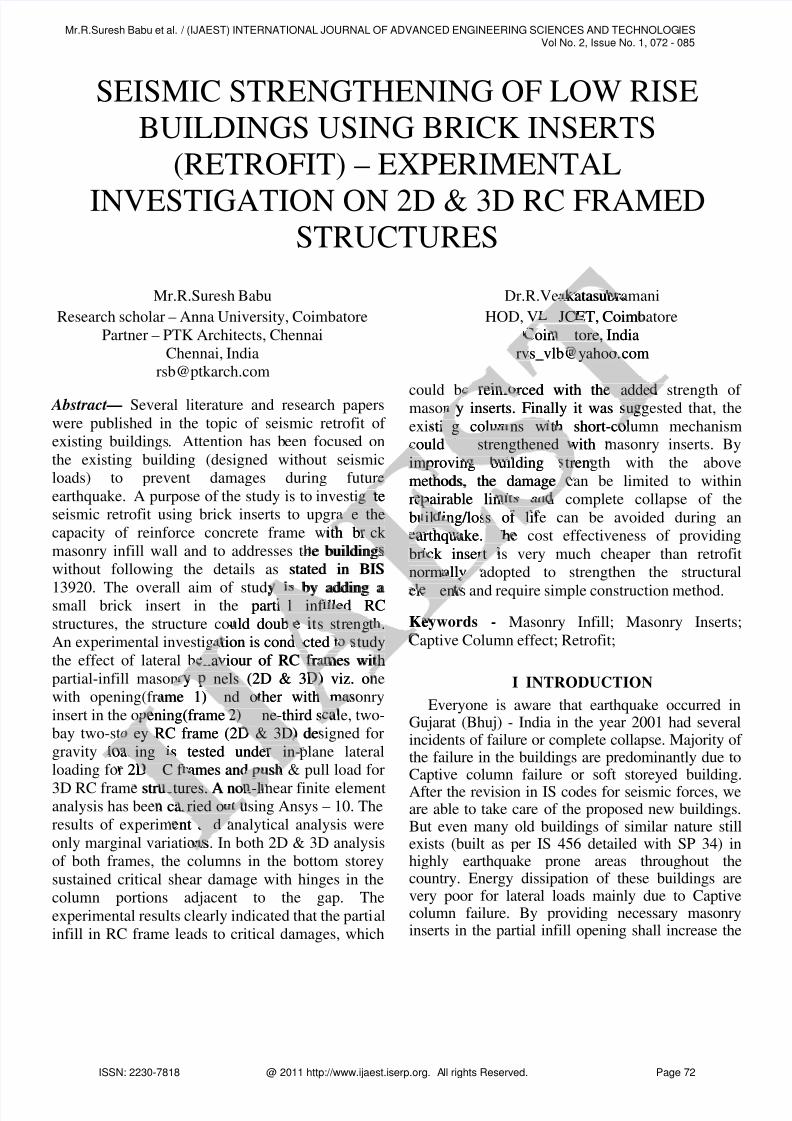
loading and ultimate base shear of 140KN was
reached in fourteenth cycle for frame 1 & 2
respectively.
Top storey deflection versus base shear is shown in
Fig.2. Load and top storey deflection is presented in
Table 1. At the ultimate base shear the top storey
deflection was found to be 47mm for frame (1) and56mm for frame (2).
Table.1: Load and Deflection for Frame 1 & 2
Frame (1) Frame (2)
Load
(KN)
Deflectio
n (mm)
Load
(KN)
Deflect
ion
(mm)
0 0 0 0
10 2 10 0.45
20 3.89 20 1
30 6 30 1.55
40 8.12 40 2.9
50 13.69 50 4.25
60 21.23 60 6.95
70 34.33 70 9.08
80 47 80 11.79
90 15.66
100 19.33
110 29
120 37130 47
140 56
Figure. 2 Base shear Vs Top storey deflection for
both frames
ii) Ductility:The ductility factor (µ) was calculated. For
frame (1), the first yield deflection (y) for the
assumed bi-linear load-deflection behaviour of the
frame was found to be 6 mm for 30 KN base shear,
while for frame (2), the same is found to be
11.79mm for 80 KN base shear. The ductility
factor value µ = (1/ y) for various load cycles of
the frames was worked out and the variation of
ductility factor for both frames with load cycles are
shown in Fig.3.The ductility factor is found to be increasing more
from 1.00 at third cycle to 7.833 at eighth cycle for
frame (1). While for frame (2), the ductility factory
is 1 at eighth cycle of loading and only 4.75 at
fourteenth cycle of loading. This behaviour shows
the reduction of ductility of frame due to the
provision of masonry insert and is shown in Fig.4
Figure. 3 Ductility factor for both frames
iii) Stiffness Degradation:The stiffness of the partially-infilled frames
for various load cycles is calculated and presented.The variation of stiffness with respect to load cycles
is shown in Fig.4. For frame (1), it may be noted
that stiffness decreases from 5 kN/mm in first cycle
to 1.7 kN/mm in eighth cycle. A sudden reduction
in stiffness takes place after the first crack
occurrence in 30 kN load.
For frame (2), the initial stiffness of frame is 20
kN/mm against 5 kN/mm for the first frame and
stiffness is sustained for a longer duration until the
development of first crack and is reduced to 2.5
kN/mm in fourteenth cycle.This behaviour shows that the initial stiffness of
frame (1) is comparatively very low and flexural
hinges and shear cracks are developed at an earlystage of loading. For frame(2) with masonry insert,
initial stiffness is increased and occurrence of
flexural hinges and shear cracks in concrete and
masonry takes place only after the eighth cycle.
Also, it could be noted that the initial stiffness is
.33
29
37474
40 5656
ar VV
g.g.
ility of
insert and is shinser
Figure. 3 Du.
iii) Stiffness DiiiThe s
for varior varihe v
is
Mr.R.Suresh Babu et al. / (IJAEST) INTERNATIONAL JOURNAL OF ADVANCED ENGINEERING SCIENCES AND TECHNOLOGIESVol No. 2, Issue No. 1, 072 - 085
ISSN: 2230-7818 @ 2011 http://www.ijaest.iserp.org. All rights Reserved. Page 74

8/7/2019 11 Ijaest Volume No 2 Issue No 1 Seismic Strengthening of Low Rise Buildings Using Brick Inserts Retrofit) 072 085
http://slidepdf.com/reader/full/11-ijaest-volume-no-2-issue-no-1-seismic-strengthening-of-low-rise-buildings 4/14
increased by 4.5 times due to the introduction of
masonry insert and the stiffness is sustained for a
longer duration of loading. The behaviour of frame
for stiffness values is shown in Fig.4
Figure:4:Stiffness degradation curve for both
frames
iv) Behaviour and Mode of Failure:
a) Frame-1 without masonry insert:
First crack was observed (horizontal hairline) at30kN at the junction of loaded side of the beam and
column at the bottom storey, where moment and
shear forces are maximum while loading further,
similar cracks were developed in the other bay
columns and flexural cracks were developed from
the junction of the loaded areas. Separation of infill
occurred at the tension corners. At the ultimate
failure load of 70 KN, crushing of loaded corner,
widening of diagonal cracks in columns and infill,
layer separation of brick infill were also observed.
Width of the cracks was ranging from 3mm to15mm in concrete and masonry. The crack pattern
indicated a combined effect of flexure and shear
failure. Also plastic hinges formation was observed
first at loaded point and later to the middle column
and finally at the leeward column. Captive column
phenomenon was identified with the failure pattern
of loaded column. It was also noticed that flow of
diagonal crack from the loaded column adjacent to
the opening was discontinuous, due to incomplete
strut action (Fig.5).
b) Frame-2 with masonry insert:
First crack observed (inclined downwards and
forwards) at only 80 kN, (against 30 kN for the
frame without insert) at loaded side of the beam and
column junction of the bottom storey where
moment and shear forces were maximum While
loading further, similar cracks were found to
propagate in middle column beam junctions and
diagonal crack were initiated in the first (loaded)
bay. Further, diagonal cracks were seen to flow
through the brick infill. Separation of infill
occurred at the tension corners. Due to the presence
of insert, diagonal cracks were observed to flow
from the loaded beam – column junction to the
diagonally opposite corner, clearly depicting theexpected strut action (Fig.6). At ultimate load of
140 KN, plastic hinge formation and failure of
frame at all bottom storey junctions were noticed.
The width of the cracks was ranging from 2mm –
10mm in concrete and masonry. The crack pattern
indicated a combined effect of flexure and shear
failure and the direction of flown crack showed the
developed strut action through the brick infill, due
to the presence of masonry insert
Figure.5.Test frame 1 with failure in the bottom and
drift of the top storey (Constructed atVLBJCET,
Coimbatore)
Figure.6.Test frame 2 with failure in the bottom and
drift of the top storey(Constructed atVLBJCET,
Coimbatore)
sonrsonr
effect of e
tion of flown crion o
ction through the bricct throu
of masonry insertf inser
m
nfillnfi
ltimatemate
ed corner,r,
ns and infill,
e also observed.
ng from 3mm tof rry. The crack patterne crack p
ct of flexure and sheard shear
ges formation was observeded
nd later to the middle columnd la
eeward column. Captive colurd co
s identified with the failured with re
umn. It was also noticed thau o noti
rack from the loaded columnrack colu
ing was discontinuous, duewas e
Fig.5)..5).
2 with masonry t h ma
ed (i(i
F
Mr.R.Suresh Babu et al. / (IJAEST) INTERNATIONAL JOURNAL OF ADVANCED ENGINEERING SCIENCES AND TECHNOLOGIESVol No. 2, Issue No. 1, 072 - 085
ISSN: 2230-7818 @ 2011 http://www.ijaest.iserp.org. All rights Reserved. Page 75

8/7/2019 11 Ijaest Volume No 2 Issue No 1 Seismic Strengthening of Low Rise Buildings Using Brick Inserts Retrofit) 072 085
http://slidepdf.com/reader/full/11-ijaest-volume-no-2-issue-no-1-seismic-strengthening-of-low-rise-buildings 5/14
A crack in leeward column of the bottom storey atthe base was also observed (Fig.7). Separation of infill occurred at the tension corners and the highstress concentration at the loaded diagonal ends ledto early crushing of the loaded corners (Fig.8).No
crack was developed in the columns, beams and inthe infill of top storey clearly depicting that theframe has failed only by hinges in columns due toshort column effect.
It is also evident from the propagation of cracks at
bottom storey level of the eighth cycle (80 kN Base
shear). Cracks in tension face of leeward column
were developed after tenth cycle of loading. Also
separation of infill from columns at highly stressed
tension faces of column were seen at tenth cycle of
loading. Further, shear flow was observed in frame
2 from the columns through the insert and brick infill, creating a largely visible crack (about 12mm
wide), which is extended to the adjacent columns.
This phenomenon is clearly exhibits the
development of strut action through masonry insert.
Figure. 7.crack in leeward Figure:8 Crushing of the
column loaded Corners
2) FINITE ELEMENT ANALYSIS – ANSYS –
10:
A comparative study was made between
experimental and analytical values. Non-linear
finite element analysis has been carried out using
ANSYS-10 software for Frame (1) & (2). The
deformed shape of the software model for ultimate
load for Frame (1) and (2) is shown in Fig.9 &10
Load – 80 KN , Deflection – 47.453
Figure.9 Ultimate Deformed Shape of thesoftware Model For Frame 1
Load – 140 KN , Deflection – 56.285
Fig.10 Ultimate Deformed Shape of thesoftware Model For Frame 2
The results obtained from analytical by ANSYS-
10 for Frame (1) & (2) are compared with
experimental results and the variation is mariginal.
The experiments conducted on the two frames
(with and without masonry insert) the following
observations are drawn.
1) It is observed in frame with masonry insert
that at a base shear of 80 kN, cracks are
initiated at the junction of the loaded and
middle end of the beam and column of the
Figure:8 Crushing of theof the
loaded Corners
ENT ANALYSIS – ANSANA
parative study was madparat s m
ntal and analytical valuesand es
nt analysis has beennalys een
ftware for Fraare fo
f the softwe soft
d (2)2
0 KN , Deflection –, Def
.9 Ultimate Deformed Shapei formesoftware Model For Frameso or Fr
Mr.R.Suresh Babu et al. / (IJAEST) INTERNATIONAL JOURNAL OF ADVANCED ENGINEERING SCIENCES AND TECHNOLOGIESVol No. 2, Issue No. 1, 072 - 085
ISSN: 2230-7818 @ 2011 http://www.ijaest.iserp.org. All rights Reserved. Page 76
8/7/2019 11 Ijaest Volume No 2 Issue No 1 Seismic Strengthening of Low Rise Buildings Using Brick Inserts Retrofit) 072 085
http://slidepdf.com/reader/full/11-ijaest-volume-no-2-issue-no-1-seismic-strengthening-of-low-rise-buildings 6/14
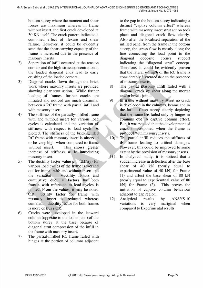
bottom storey where the moment and shear
forces are maximum whereas in frame
without insert, the first crack developed at
30 KN itself. The crack pattern indicated a
combined effect of flexure and shear
failure. However, it could be evidently
seen that the shear carrying capacity of theframe is increased due to the presence of
masonry inserts
2) Separation of infill occurred at the tension
corners and the high stress concentration at
the loaded diagonal ends lead to early
crushing of the loaded corners.
3) Diagonal cracks flown through the brick
work where masonry inserts are provided
showing clear strut action. While further
loading of frames, further cracks are
initiated and noticed are much dissimilarbetween a RC frame with partial infill and
with masonry insert.
4) The stiffness of the partially-infilled frame
with and without insert for various load
cycles is calculated and the variation of
stiffness with respect to load cycles is
plotted. The stiffness of the brick infilled
RC frame with masonry insert is observed
to be very high when compared to frame
without insert. This shows greater
increase of stiffness while introducingmasonry insert.
5) The ductility factor value µ = (1/ y) for
various load cycles of the frame is worked
out for frames with and without insert and
the variation of ductility factors and
cumulative ductility factors for both
frames with reference to load cycles is
plotted. From the values, it may be noted
that ductility factor for frame with
masonry insert is reduced whereas
cumulative ductility factor for both frames
is more or less same.
6) Cracks were developed in the leeward
column (opposite to the loaded end) of the
bottom storey at the base because of
diagonal strut compression of the infill in
the frame with masonry insert.
7) The partial-infilled RC frame failed with
hinges at the portion of columns adjacent
to the gap in the bottom storey indicating a
distinct “captive column effect” whereas
frame with masonry insert strut action took
place and diagonal crack flow clearly.
Also after the localised separation of the
infilled panel from the frame in the bottom
storey, the stress flow is mostly along theline connecting the load point to the
diagonal opposite corner support
indicating the “diagonal strut” concept.
Therefore, it could be evidently proven
that the lateral strength of the RC frame is
considerably increased due to the presence
of masonry inserts.
8) The partial masonry infill failed with a
diagonal crack by shear along the mortar
and/or bricks joints.
9) In frame without masonry insert no crack is developed in the columns, beams and in
the infill of top storey clearly depicting
that the frame has failed only by hinges in
columns due to captive column effect.
But, it was noticed that the development of
crack is postponed when the frame is
provided with masonry inserts.
10) The partial infill reduces the stiffness of
the frame leading to critical damages.
However, this could be improved to some
extent by the provision of masonry inserts. 11) In analytical study, it is noticed that a
sudden increase in deflection after the base
shear of 40 kN (nearly equal to
experimental value of 40 kN) for Frame
(1) and affect the base shear of 80 kN
(nearly equal to experiemtnal value of 80
kN) for Frame (2). This proves the
initiation of captive column behaviour
adjacent to gap region.
12) Analytical results by ANSYS-10
variations is very mariginal when
compared to Experimental results
rengteng
ncreasedn
inserts.insert .
tial masonry infill f i asonr
nal crack by shear along tl she
d/or bricks joints.
f
s iss
nfillednf illed
observeded
red to frame
shows greater
while introducinghile
r value µ = ( 1/ 1/ y) fory) for
cles of the frame is workedl ed
s with and without insert ands wi i
tion of ductility factorsof
tive ductility factors fortility f
es with reference to loade ce to
otted. From the values, it motte . es, it
hat ductility factor forduc or
sonry insert is rery in
lative ductility fave duc
or less samess sam
re ded
n frame without masonry innry iis developed in the column
the infill of top storeyill of
that the frame has faithat the frame h
columns due tot
But, it was notii
crack is pos o
provided
10) The pe p
thee
1
Mr.R.Suresh Babu et al. / (IJAEST) INTERNATIONAL JOURNAL OF ADVANCED ENGINEERING SCIENCES AND TECHNOLOGIESVol No. 2, Issue No. 1, 072 - 085
ISSN: 2230-7818 @ 2011 http://www.ijaest.iserp.org. All rights Reserved. Page 77

8/7/2019 11 Ijaest Volume No 2 Issue No 1 Seismic Strengthening of Low Rise Buildings Using Brick Inserts Retrofit) 072 085
http://slidepdf.com/reader/full/11-ijaest-volume-no-2-issue-no-1-seismic-strengthening-of-low-rise-buildings 7/14
IV EXPERIMENTAL AND ANALYTICAL
INVESTIGATION ON 3D RC FRAME
STRUCTURE
1) EXPERIMENTAL INVESTIGATION
A) Modelling of Frames:A structure representing a multi-storeyed frame
system is analysed and designed. The structure is
modeled for experimental investigation by scaling
down the geometric properties of the prototype
using the laws of Geometric similitude.
Figure.11 Geometry of the 3D frame model 1&2
B) DETAILS OF TEST FRAME
Test models was fabricated to 1:3 reduced scale
following the laws of similitude by scaling down
the geometric and material properties of the
prototype for Frame (1) and Frame (2)(Ref. Fig.11).
C) Testing Procedure :
Lumped mass distribution wascalculated and lateral loads were distributed as 75%
for top storey & 25% for bottom storey. All applied
lateral loads were divided accordingly and applied
as push and pull method. Frame (1) was tested of
first incremental Push load of 5 KN and released to
zero and a pull load of 5 KN and released to zero.
The deflections at top storey levels were recorded.
Further an incremental load of 5 KN(Push and Pull)
were applied and top storey deflections were
measured at each increment and decrement of the
load Using LVDT. Additional LVDT also placed at
other levels to find the frame behavior. The
formation and propagation of cracks, hinge
formation and failure pattern were recorded. This
procedure was repeated for frame (2) with masonryinsert.
D) Results:
The results of various parameters like load Vs.
deflection, stiffness degradation and ductility factor
were considered for study of the captive column
behaviour of the frame
i) Loading And Load-Deflection Behaviour
(P- ∆ ):
The frame was subjected to push and pullloading. The push and pull load was applied in
increment of 5 kN base shear for each cycle and
released to zero after each cycle. The deflections at
top storey levels were measured using LVDT at
each increment or decrement of load. The ultimate
base shear of 105 KN was reached in the twenty
first cycle of loading and ultimate base shear of
195KN was reached in thirty nine cycle for frame 1
& 2 respectively.
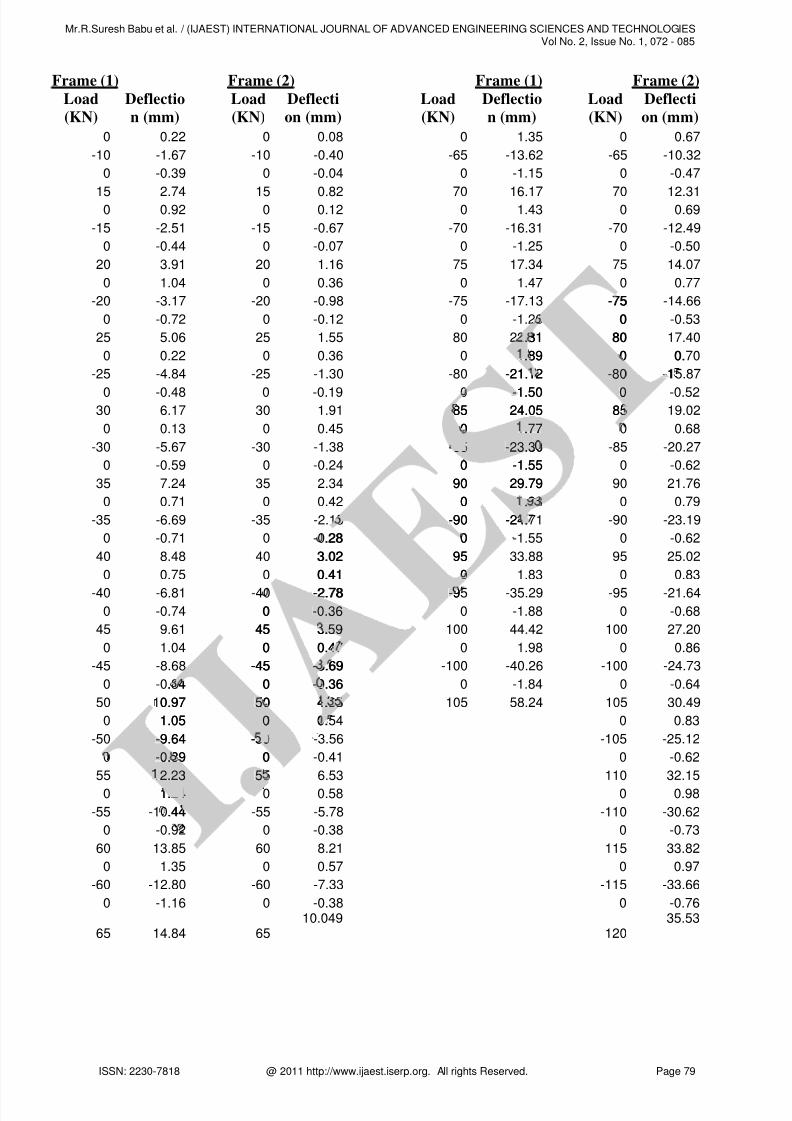
The push pull curve for top storey displacement
versus base shear for both frames is represented inFig.12 & 13. Load and top storey deflection is
presented in Table 2. At the ultimate base shear the
top storey deflection was found to be 58.24mm for
frame (1) and 71.15mm for frame (2).
Table.2: Load and Deflection for Frame 1 & 2
Frame (1) Frame (2)
Load
(KN)
Deflectio
n (mm)
Load
(KN)
Deflecti
on (mm)
0 0.00 0 0.00
5 0.75 5 0.27
0 0.08 0 0.02
-5 -0.66 -5 -0.19
0 -0.02 0 -0.01
10 1.60 10 0.54
me model 1&2
ricated to 1:3 reduced scaleri e e
of similitude by scaling dowf sim a
nd material properties of aterial s
rame (1) and Frame (2)(Ref. FFram . F
ing Procedure :Proce
umped mass ded dlateral loads weral loa
% for bof or bo
vide
atioati
udy of t
ee
And Load-Deflection A oad-
):
rame was subjected to pur e to pu. The push and pull loadd
ement of 5 kN base shear f
leased to zero after each cycld to zero after eac
op storey levels were meo le
ach increment or decre
base shear of 105 Ka
first cycle of loadist a
195KN was reac9 re
& 2 respective& v
The pusThe
versussusFig..
p
Mr.R.Suresh Babu et al. / (IJAEST) INTERNATIONAL JOURNAL OF ADVANCED ENGINEERING SCIENCES AND TECHNOLOGIESVol No. 2, Issue No. 1, 072 - 085
ISSN: 2230-7818 @ 2011 http://www.ijaest.iserp.org. All rights Reserved. Page 78
8/7/2019 11 Ijaest Volume No 2 Issue No 1 Seismic Strengthening of Low Rise Buildings Using Brick Inserts Retrofit) 072 085
http://slidepdf.com/reader/full/11-ijaest-volume-no-2-issue-no-1-seismic-strengthening-of-low-rise-buildings 8/14
Frame (1) Frame (2)
Load
(KN)
Deflectio
n (mm)
Load
(KN)
Deflecti
on (mm)
0 0.22 0 0.08
-10 -1.67 -10 -0.40
0 -0.39 0 -0.04
15 2.74 15 0.82
0 0.92 0 0.12
-15 -2.51 -15 -0.67
0 -0.44 0 -0.07
20 3.91 20 1.16
0 1.04 0 0.36
-20 -3.17 -20 -0.98
0 -0.72 0 -0.12
25 5.06 25 1.55
0 0.22 0 0.36
-25 -4.84 -25 -1.30
0 -0.48 0 -0.19
30 6.17 30 1.91
0 0.13 0 0.45
-30 -5.67 -30 -1.38
0 -0.59 0 -0.24
35 7.24 35 2.34
0 0.71 0 0.42
-35 -6.69 -35 -2.15
0 -0.71 0 -0.28
40 8.48 40 3.02
0 0.75 0 0.41
-40 -6.81 -40 -2.78
0 -0.74 0 -0.36
45 9.61 45 3.59
0 1.04 0 0.47
-45 -8.68 -45 -3.69
0 -0.84 0 -0.36
50 10.97 50 4.35
0 1.05 0 0.54
-50 -9.64 -50 -3.56
0 -0.89 0 -0.41
55 12.23 55 6.53
0 1.24 0 0.58
-55 -10.44 -55 -5.78
0 -0.92 0 -0.38
60 13.85 60 8.21
0 1.35 0 0.57
-60 -12.80 -60 -7.33
0 -1.16 0 -0.38
65 14.84 65
10.049
Frame (1) Frame (2)
Load
(KN)
Deflectio
n (mm)
Load
(KN)
Deflecti
on (mm)
0 1.35 0 0.67
-65 -13.62 -65 -10.32
0 -1.15 0 -0.47
70 16.17 70 12.31
0 1.43 0 0.69
-70 -16.31 -70 -12.49
0 -1.25 0 -0.50
75 17.34 75 14.07
0 1.47 0 0.77
-75 -17.13 -75 -14.66
0 -1.26 0 -0.53
80 22.81 80 17.40
0 1.89 0 0.70
-80 -21.12 -80 -15.87
0 -1.50 0 -0.52
85 24.05 85 19.02
0 1.77 0 0.68
-85 -23.30 -85 -20.27
0 -1.55 0 -0.62
90 29.79 90 21.76
0 1.93 0 0.79
-90 -24.71 -90 -23.19
0 -1.55 0 -0.62
95 33.88 95 25.02
0 1.83 0 0.83
-95 -35.29 -95 -21.64
0 -1.88 0 -0.68
100 44.42 100 27.20
0 1.98 0 0.86
-100 -40.26 -100 -24.73
0 -1.84 0 -0.64
105 58.24 105 30.49
0 0.83
-105 -25.12
0 -0.62
110 32.15
0 0.98
-110 -30.62
0 -0.73
115 33.82
0 0.97
-115 -33.66
0 -0.76
120
35.53
.28
3.02
0.41
-2.78
0 -0.36-0.36
45 3.59.59
0 0.47
-45 -3.69-
. 4 0 -0.36-
0.97 505 4.35.
1.05 00 0.
-9.64- -500
-0.89-0. 0
2.232.23 555
1.2424
.44
-75
0
.81. 80
.89. 0 0.
-21.12 -80-80 -1
-1.50- 00
85 24.05 85
0 .77.77
-8585 -23.30-23.3
0 -1.55
90 29.79
0 .93.
-90 -24..
0
95
0
-9-
Mr.R.Suresh Babu et al. / (IJAEST) INTERNATIONAL JOURNAL OF ADVANCED ENGINEERING SCIENCES AND TECHNOLOGIESVol No. 2, Issue No. 1, 072 - 085
ISSN: 2230-7818 @ 2011 http://www.ijaest.iserp.org. All rights Reserved. Page 79

8/7/2019 11 Ijaest Volume No 2 Issue No 1 Seismic Strengthening of Low Rise Buildings Using Brick Inserts Retrofit) 072 085
http://slidepdf.com/reader/full/11-ijaest-volume-no-2-issue-no-1-seismic-strengthening-of-low-rise-buildings 9/14
Frame (2)
Load
(KN)
Deflecti
on (mm)
0 1.05
-120 -36.92
0 -0.83
125 36.92
0 0.99
-125 -35.63
0 -0.80
130 37.95
0 1.08
-130 -41.47
0 -1.00
135 40.00
0 1.30
-135 -44.96
0 -0.96
140 41.20
0 1.40
-140 -37.90
0 -1.08
145 43.66
0 1.53
-145 -41.76
0 -1.07
150 45.22
0 1.48
-150 -42.94
0 -1.14
155 47.72
0 1.93
-155 -49.08
0 -1.38
160 51.78
0 1.96
-160 -51.04
0 -1.55
165 54.42
0 2.12
-165 -52.99
0 -1.71
170 57.65
0 2.08
-170 -52.01
0 -1.69
Frame (2)
Load
(KN)
Deflecti
on (mm)
175 60.97
0 2.13
-175 -60.81
0 -2.12
180 63.09
0 2.70
-180 -65.89
0 -2.20
185 65.72
0 2.93
-185 -55.88
0 -2.56
190 67.63
0 3.04
-190 -61.93
0 -2.47
195 71.15
Figure. 12 Push and Pull curve for Frame 1
Figure. 12 Push and Pull curve for Frame 1
Figure. 12 Push and Pull Curve for Frame 1
Figure. 13 Push and Pull Curve for Frame 2 I
.07
45.22
1.48
-42.94-
0 -1.14-1.14
155 47.72.72
0 1.93
-155 -49.08-
0 -1.38-1
16016 51.78.
00 1.
-1600 -
0
16516
0
-185
0
1901 6 .
00
-19090 0
19
Mr.R.Suresh Babu et al. / (IJAEST) INTERNATIONAL JOURNAL OF ADVANCED ENGINEERING SCIENCES AND TECHNOLOGIESVol No. 2, Issue No. 1, 072 - 085
ISSN: 2230-7818 @ 2011 http://www.ijaest.iserp.org. All rights Reserved. Page 80

8/7/2019 11 Ijaest Volume No 2 Issue No 1 Seismic Strengthening of Low Rise Buildings Using Brick Inserts Retrofit) 072 085
http://slidepdf.com/reader/full/11-ijaest-volume-no-2-issue-no-1-seismic-strengthening-of-low-rise-buildings 10/14
ii) Ductility:The ductility factor (µ) was calculated. For frame
(1), the first yield deflection (y) for the assumed
bi-linear load-deflection behaviour of the frame was
found to be 8.48 mm for 40 KN base shear, while
for frame (2), the same is found to be 14.06mm for
75 KN base shear. The ductility factor value µ =(1/ y) for various load cycles of the frames was
worked out and the variation of ductility factor for
both frames with load cycles are shown in Fig.14.
The ductility factor is found to be increasing more
from 1 at eighth cycle to 6.86 at twenty first cycle
for frame (1). While for frame (2), the ductility
factory is 1 at fifteenth cycle of loading and only
5.05 at thirty nine cycle of loading. This behaviour
shows the reduction of ductility of frame due to the
provision of masonry insert and is shown in Fig.4
Figure. 14 Ductility factor for both frames
iii) Stiffness Degradation:The stiffness of the partially-infilled frames for
various load cycles is calculated and presented. The
variation of stiffness with respect to load cycles is
shown in Fig.15. For frame (1), it may be noted
that stiffness decreases from 6.7KN/mm in first
cycle to 1.8 KN/mm in twenty first cycle. A sudden
reduction in stiffness takes place after the first crack
occurrence in 40 kN load.
For frame (2), the initial stiffness of frame is
18.69 KN/mm against 6.7 kN/mm for the first frame
and stiffness is sustained for a longer duration until
the development of first crack and is reduced to
2.74 KN/mm in Thirty nine cycle.
This behaviour shows that the initial stiffness of
frame (1) is comparatively very low and flexuralhinges and shear cracks are developed at an early
stage of loading. For frame(2) with masonry insert,
initial stiffness is increased and occurrence of
flexural hinges and shear cracks in concrete and
masonry takes place only after the Fifteenth cycle.
Also, it could be noted that the initial stiffness is
increased by 2.8 times due to the introduction of
masonry insert and the stiffness is sustained for a
longer duration of loading. The behaviour of framefor stiffness values is shown in Fig.15
Figure:15:Stiffness degradation curve for both
frames
iv) Behaviour and Mode of Failure:
a) Frame-1 without masonry insert:
First crack was observed (horizontal hairline) at
40kN at the junction of loaded side of the beam and
column at the bottom storey, where moment andshear forces are maximum while loading further,
similar cracks were developed in the other bay
columns and flexural cracks were developed from
the junction of the loaded areas. Separation of infill
occurred at the tension corners. At the ultimate
failure load of 100 KN, crushing of loaded corner,
widening of diagonal cracks in columns and infill,
layer separation of brick infill were also observed.
Width of the cracks was ranging from 3mm to
17mm in concrete and masonry. The crack pattern
indicated a combined effect of flexure and shear
failure. Also plastic hinges formation was observed
first at loaded point and later to the middle column
and finally at the leeward column. Captive column
phenomenon was identified with the failure pattern
of loaded column. It was also noticed that flow of
diagonal crack from the loaded column adjacent to
the opening was discontinuous, due to incomplete
strut action (Fig.16).
both frames
on:artially-infilled frames f orf or
calculated and presented. Thecalcu s
ss with respect to load cycleith res
. For frame (1), it may beme ( e
decreases from 6.7KN/mm6.7
. KN/mm in twenty first cycle. KN rst cy
in stiffness takes place aftertiffne ter
n 40 kN load.kN l
(2), the initial sthe i
ainst .7 kNt .7 k
inedd
r
Figure:15:Stiffness degradigure:15:Stiffness
framera
iv) Behaviour and M n
a) Frame-1 withou a tho
First cracc
0kN at th0kN
olumnlumshear
si
Mr.R.Suresh Babu et al. / (IJAEST) INTERNATIONAL JOURNAL OF ADVANCED ENGINEERING SCIENCES AND TECHNOLOGIESVol No. 2, Issue No. 1, 072 - 085
ISSN: 2230-7818 @ 2011 http://www.ijaest.iserp.org. All rights Reserved. Page 81

8/7/2019 11 Ijaest Volume No 2 Issue No 1 Seismic Strengthening of Low Rise Buildings Using Brick Inserts Retrofit) 072 085
http://slidepdf.com/reader/full/11-ijaest-volume-no-2-issue-no-1-seismic-strengthening-of-low-rise-buildings 11/14
Figure.16.Test frame 1 with failure in the bottom
and drift of the top storey (Constructed
atVLBJCET, Coimbatore)
b) Frame-2 with masonry insert:
First crack observed (inclined downwards and
forwards) at only 75 kN, (against 40 kN for the
frame without insert) at loaded side of the beam and
column junction of the bottom storey where
moment and shear forces were maximum Whileloading further, similar cracks were found to
propagate in middle column beam junctions and
diagonal crack were initiated in the first (loaded)
bay. Further, diagonal cracks were seen to flow
through the brick infill. Separation of infill
occurred at the tension corners. Due to the presence
of insert, diagonal cracks were observed to flow
from the loaded beam – column junction to the
diagonally opposite corner, clearly depicting the
expected strut action (Fig.17). At ultimate load of
195 KN, plastic hinge formation and failure of frame at all bottom storey junctions were noticed.
The width of the cracks was ranging from 2mm –
10mm in concrete and masonry. The crack pattern
indicated a combined effect of flexure and shear
failure and the direction of flown crack showed the
developed strut action through the brick infill, due
to the presence of masonry insert
Figure.17.Test frame 2 with failure in the bottomand drift of the top storey(Constructed atVLBJCET,
Coimbatore)
A crack in leeward column of the bottom storey atthe base was also observed (Fig.18). Separation of infill occurred at the tension corners and the highstress concentration at the loaded diagonal ends ledto early crushing of the loaded corners (Fig.19).Nocrack was developed in the columns, beams and in
the infill of top storey clearly depicting that theframe has failed only by hinges in columns due toshort column effect.
It is also evident from the propagation of cracks at
bottom storey level of the Fifteenth cycle (75 kN
Base shear). Cracks in tension face of leeward
column were developed after twenty first cycle of
loading. Also separation of infill from columns at
highly stressed tension faces of column were seen at
tenth cycle of loading. Further, shear flow was
observed in frame 2 from the columns through the
insert and brick infill, creating a largely visiblecrack (about 12mm wide), which is extended to the
adjacent columns. This phenomenon is clearly
exhibits the development of strut action through
masonry insert.
s andan
for thethe
e beam and
storey where
maximum Whilem s were found towere
n beam junctions andnctions a
ated in the first (loaded)oaded)
l cracks were seen to flowc
infill. Separation of inf infill.
sion corners. Due to the presrners. e
onal cracks were observedwere
aded beam – column junctiad umn
y opposite corner, clearlyoppos rly
trut action (Fig.17). Ataction
stic hinge formatihing atitom storey justore
racks ws w
gure.17.Test frame 2 with failg id drift of the top storey(Constrift o the top store
oimbatoim
A crack in leeward coluhe base was also obsa s
infill occurred at thf il tstress concentratir c nto early crushio shrack wasrac
he infille inframee sho
Mr.R.Suresh Babu et al. / (IJAEST) INTERNATIONAL JOURNAL OF ADVANCED ENGINEERING SCIENCES AND TECHNOLOGIESVol No. 2, Issue No. 1, 072 - 085
ISSN: 2230-7818 @ 2011 http://www.ijaest.iserp.org. All rights Reserved. Page 82

8/7/2019 11 Ijaest Volume No 2 Issue No 1 Seismic Strengthening of Low Rise Buildings Using Brick Inserts Retrofit) 072 085
http://slidepdf.com/reader/full/11-ijaest-volume-no-2-issue-no-1-seismic-strengthening-of-low-rise-buildings 12/14
Figure 18.crack in leeward Figure.19 Crushing of the
column loaded Corners
2) FINITE ELEMENT ANALYSIS – ANSYS –
10:
A comparative study was made between
experimental and analytical values. Non-linear
finite element analysis has been carried out usingANSYS-10 software for Frame (1) & (2). The
deformed shape of the software model for ultimate
load for Frame (1) and (2) is shown in Fig.20 &21
Load – 105 KN , Deflection – 59.432
Figure.20 Ultimate Deformed Shape of thesoftware Model For Frame 1
Load – 195 KN , Deflection – 70.448
Fig.21 Ultimate Deformed Shape of thesoftware Model For Frame 2
The results obtained from analytical by ANSYS-
10 for Frame (1) & (2) are compared with
experimental results and the variation is mariginal.
The experiments conducted on the two frames
(with and without masonry insert) the following
observations are drawn.
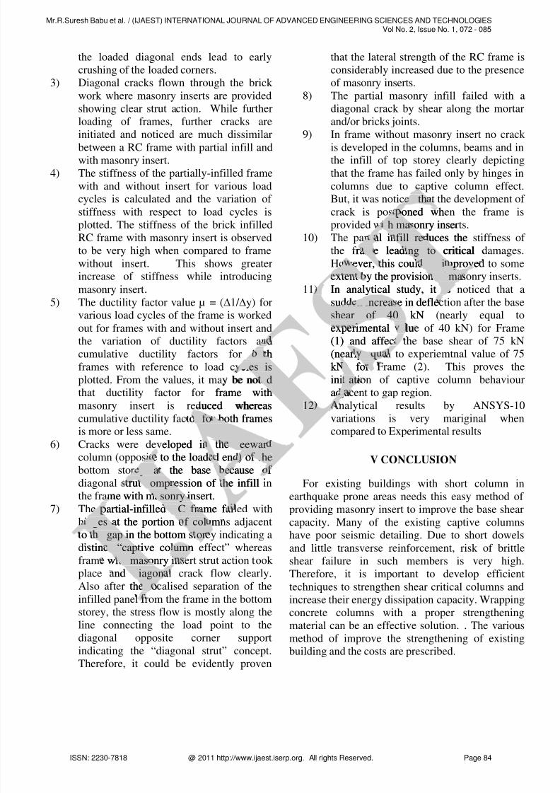
1) It is observed in frame with masonry insert
that at a base shear of 75 kN, cracks are
initiated at the junction of the loaded and
middle end of the beam and column of the
bottom storey where the moment and shear
forces are maximum whereas in frame
without insert, the first crack developed at
40 KN itself. The crack pattern indicated acombined effect of flexure and shear
failure. However, it could be evidently
seen that the shear carrying capacity of the
frame is increased due to the presence of
masonry inserts
2) Separation of infill occurred at the tension
corners and the high stress concentration at
05 KN , DeN ,
atee
Load – 195 KN , Doad – ,
Fig.21 Ultimatesoftwaro a
The results obte lts
10 for Fram1 m
xperimentaxp
TheTh
Mr.R.Suresh Babu et al. / (IJAEST) INTERNATIONAL JOURNAL OF ADVANCED ENGINEERING SCIENCES AND TECHNOLOGIESVol No. 2, Issue No. 1, 072 - 085
ISSN: 2230-7818 @ 2011 http://www.ijaest.iserp.org. All rights Reserved. Page 83
8/7/2019 11 Ijaest Volume No 2 Issue No 1 Seismic Strengthening of Low Rise Buildings Using Brick Inserts Retrofit) 072 085
http://slidepdf.com/reader/full/11-ijaest-volume-no-2-issue-no-1-seismic-strengthening-of-low-rise-buildings 13/14
the loaded diagonal ends lead to early
crushing of the loaded corners.
3) Diagonal cracks flown through the brick
work where masonry inserts are provided
showing clear strut action. While further
loading of frames, further cracks are
initiated and noticed are much dissimilarbetween a RC frame with partial infill and
with masonry insert.
4) The stiffness of the partially-infilled frame
with and without insert for various load
cycles is calculated and the variation of
stiffness with respect to load cycles is
plotted. The stiffness of the brick infilled
RC frame with masonry insert is observed
to be very high when compared to frame
without insert. This shows greater
increase of stiffness while introducingmasonry insert.
5) The ductility factor value µ = (1/ y) for
various load cycles of the frame is worked
out for frames with and without insert and
the variation of ductility factors and
cumulative ductility factors for both
frames with reference to load cycles is
plotted. From the values, it may be noted
that ductility factor for frame with
masonry insert is reduced whereas
cumulative ductility factor for both framesis more or less same.
6) Cracks were developed in the leeward
column (opposite to the loaded end) of the
bottom storey at the base because of
diagonal strut compression of the infill in
the frame with masonry insert.
7) The partial-infilled RC frame failed with
hinges at the portion of columns adjacent
to the gap in the bottom storey indicating a
distinct “captive column effect” whereas
frame with masonry insert strut action took
place and diagonal crack flow clearly.
Also after the localised separation of the
infilled panel from the frame in the bottom
storey, the stress flow is mostly along the
line connecting the load point to the
diagonal opposite corner support
indicating the “diagonal strut” concept.
Therefore, it could be evidently proven
that the lateral strength of the RC frame is
considerably increased due to the presence
of masonry inserts.
8) The partial masonry infill failed with a
diagonal crack by shear along the mortar
and/or bricks joints.
9) In frame without masonry insert no crack is developed in the columns, beams and in
the infill of top storey clearly depicting
that the frame has failed only by hinges in
columns due to captive column effect.
But, it was noticed that the development of
crack is postponed when the frame is
provided with masonry inserts.
10) The partial infill reduces the stiffness of
the frame leading to critical damages.
However, this could be improved to some
extent by the provision of masonry inserts. 11) In analytical study, it is noticed that a
sudden increase in deflection after the base
shear of 40 kN (nearly equal to
experimental value of 40 kN) for Frame
(1) and affect the base shear of 75 kN
(nearly equal to experiemtnal value of 75
kN) for Frame (2). This proves the
initiation of captive column behaviour
adjacent to gap region.
12) Analytical results by ANSYS-10
variations is very mariginal whencompared to Experimental results
V CONCLUSION
For existing buildings with short column in
earthquake prone areas needs this easy method of
providing masonry insert to improve the base shear
capacity. Many of the existing captive columns
have poor seismic detailing. Due to short dowels
and little transverse reinforcement, risk of brittle
shear failure in such members is very high.
Therefore, it is important to develop efficient
techniques to strengthen shear critical columns and
increase their energy dissipation capacity. Wrapping
concrete columns with a proper strengthening
material can be an effective solution. . The various
method of improve the strengthening of existing
building and the costs are prescribed.
d
otho
cles iscles is
be noteded
frame with
uced whereas
or for both framesr fo
eloped in the leewardleewar
te to the loaded end) of thethe
ey at the base because of y a e
trut compression of the infillcomp h
e with masonry insert.asonry
partial-infilled RC frame faiRC fr
nges at the portion of columnges f col
o the gap in the bottom store gap or
tinct “captive columnt “cap um
with masonry inth mas
nd diagonadiagon
the lol
f
d thad th
poned wh
th masonry inseth ma
ial infill reduces thei fill re
rame leading to criticalm ng to
wever, this could be improvebe i
extent by the provision of masof maIn analytical study, it isis
sudden increase in deflen increa
shear of 40 kNshear of 40
experimental valua
(1) and affect
(nearly equae
kN) for)
initiatiiat
adja j
12)12
Mr.R.Suresh Babu et al. / (IJAEST) INTERNATIONAL JOURNAL OF ADVANCED ENGINEERING SCIENCES AND TECHNOLOGIESVol No. 2, Issue No. 1, 072 - 085
ISSN: 2230-7818 @ 2011 http://www.ijaest.iserp.org. All rights Reserved. Page 84
8/7/2019 11 Ijaest Volume No 2 Issue No 1 Seismic Strengthening of Low Rise Buildings Using Brick Inserts Retrofit) 072 085
http://slidepdf.com/reader/full/11-ijaest-volume-no-2-issue-no-1-seismic-strengthening-of-low-rise-buildings 14/14
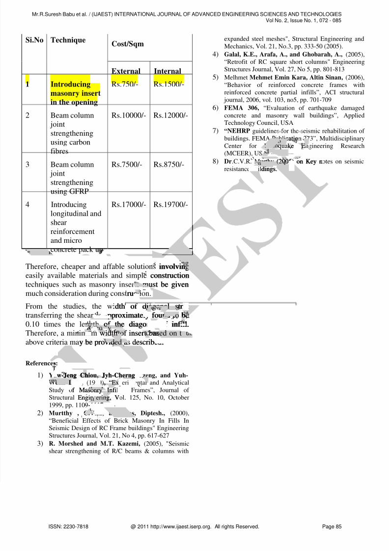
Cost/SqmSi.No Technique
External Internal
1 Introducing
masonry insertin the opening
Rs.750/- Rs.1500/-
2 Beam column
joint
strengthening
using carbon
fibres
Rs.10000/- Rs.12000/-
3 Beam column
joint
strengthening
using GFRP
Rs.7500/- Rs.8750/-
4 Introducing
longitudinal and
shear
reinforcement
and micro
concrete pack up
Rs.17000/- Rs.19700/-
Therefore, cheaper and affable solutions involving
easily available materials and simple construction
techniques such as masonry inserts must be given
much consideration during construction.
From the studies, the width of diagonal strut
transferring the shear is approximately found to be
0.10 times the length of the diagonal of infill.
Therefore, a minimum width of insert based on the
above criteria may be provided as described.
References:
1) Yaw-Jeng Chiou, Jyh-Cherng Tzeng, and Yuh-Wehn Liou, (1999), “Experimental and Analytical
Study of Masonry Infilled Frames”, Journal of
Structural Engineering, Vol. 125, No. 10, October
1999, pp. 1109-1117
2) Murtthy , C.V.R., and Das, Diptesh., (2000),
“Beneficial Effects of Brick Masonry In Fills In
Seismic Design of RC Frame buildings" Engineering
Structures Journal, Vol. 21, No 4, pp. 617-627
3) R. Morshed and M.T. Kazemi, (2005), "Seismicshear strengthening of R/C beams & columns with
expanded steel meshes", Structural Engineering and
Mechanics, Vol. 21, No.3, pp. 333-50 (2005).
4) Galal, K.E., Arafa, A., and Ghobarah, A., (2005),“Retrofit of RC square short columns" Engineering
Structures Journal, Vol. 27, No 5, pp. 801-813
5) Melhmet Mehmet Emin Kara, Altin Sinan, (2006),
“Behavior of reinforced concrete frames with
reinforced concrete partial infills”, ACI structural
journal, 2006, vol. 103, no5, pp. 701-709
6) FEMA 306, “Evaluation of earthquake damaged
concrete and masonry wall buildings”, AppliedTechnology Council, USA
7) “NEHRP guidelines for the seismic rehabilitation of
buildings. FEMA Publication 273”, Multidisciplinary
Center for Earthquake Engineering Research
(MCEER), USA
8) Dr.C.V.R. Murthy (2005) on Key notes on seismic
resistance buildings.
icatiocatio
quake E
involving
construction
s must be given
ruction.tion.
dth of diagonal strutonal str
pproximately found to beto be
of the diagonal of infill.o l.
m width of insert based on twidth a
y be provided as described.vided .
w-Jeng Chiou, Jyh-Cherngng ChLiou,u, (1999)(19 , “Experimperi
f Masonry Infilledasonry
Engineering, Veering,
-111717
.R.
urthy (2005) on Key nu (200
uildings.uil
Mr.R.Suresh Babu et al. / (IJAEST) INTERNATIONAL JOURNAL OF ADVANCED ENGINEERING SCIENCES AND TECHNOLOGIESVol No. 2, Issue No. 1, 072 - 085
ISSN 2230 7818 @ 2011 htt // ij t i All i ht R d P 85


![rethinking-precollege-math.wikispaces.comrethinking-precollege-math.wikispaces.com/file/view/IA... · Web viewEither MATH 072 [elementary algebra], 085 [technical mathematics I],](https://img.dokumen.tips/doc/110x75/5aa1927d7f8b9a1f6d8c133c/rethinking-precollege-math-vieweither-math-072-elementary-algebra-085-technical.jpg)