Embed Size (px)
Citation preview
Copyright 2002 by Hans H. Jucker. Published in the Tube Collector Association Bulletin, Medford OR 97501, U.S.A. October 2002
Early German and American Radar Transmitter Technology
Initially radar engineers worked with commercially available transmitter tubes. The very high voltage operation in radar transmitters caused serious positive ion bom-bardments of the cathode. Therefore only tungsten cathodes or thoriated tungsten cathodes with their rather limited electron emission were sufficiently robust for this service. In 1937 Dr. Felix Herringer of the Lorenz electron tube laboratory mastered the development of an oxide cathode tube, suitable for pulse modulated UHF radar transmitters. The C. Lorenz company filed 1938 for the new type of tube, the patent Nr. 862782 “Anodenimpulsmodelung bei Röhren mit Oxydkathode”
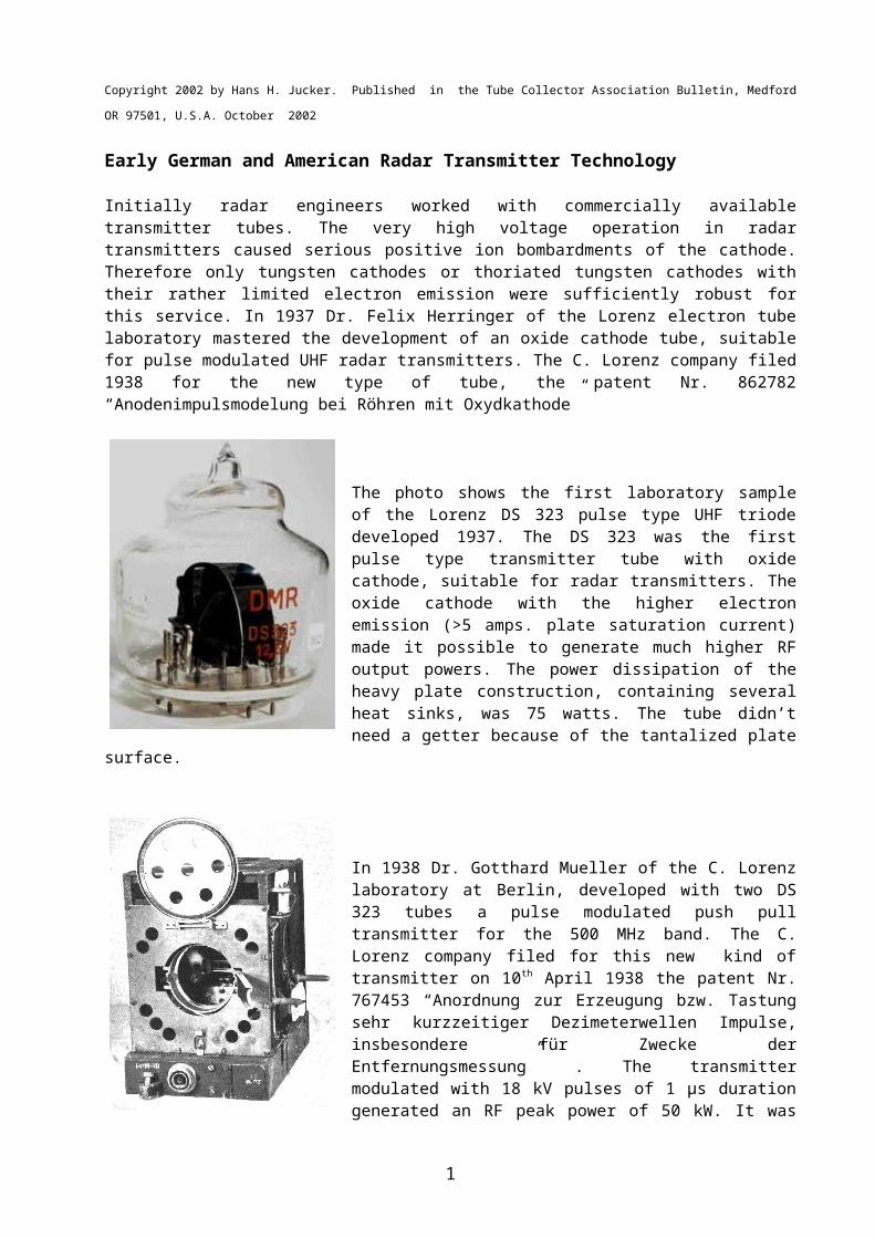
The photo shows the first laboratory sample of the Lorenz DS 323 pulse type UHF triode developed 1937. The DS 323 was the first pulse type transmitter tube with oxide cathode, suitable for radar transmitters. The oxide cathode with the higher electron emission (>5 amps. plate saturation current) made it possible to generate much higher RF output powers. The power dissipation of the heavy plate construction, containing several heat sinks, was 75 watts. The tube didn’t need a getter because of the tantalized plate surface.
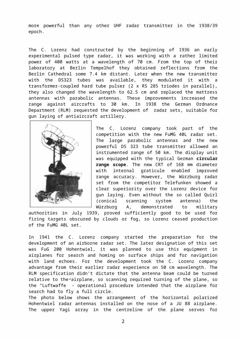
In 1938 Dr. Gotthard Mueller of the C. Lorenz laborat-ory at Berlin, developed with two DS 323 tubes a pulse modulated push pull transmitter for the 500 MHz band. The C. Lorenz company filed for this new kind of transmitter on 10th April 1938 the patent Nr. 767453 “Anordnung zur Erzeugung bzw. Tastung sehr kurzzeitiger Dezimeterwellen Impulse, insbesondere für Zwecke der Entfernungsmessung” . The transmitter modulated with 18 kV pulses of 1 µs duration generated an RF peak power of 50 kW. It was more powerful than any other UHF radar trans-mitter in the 1938/39 epoch.
The C. Lorenz had constructed by the beginning of 1936 an early experimental pulsed type radar, it was working with a rather limited power of 400 watts at a wavelength of 70 cm. From the top of their laboratory at Berlin Tempelhof they ob-tained reflections from the Berlin Cathedral some 7.4 km distant. Later when the new transmitter with the DS323 tubes was available, they modulated it with a trans-former-coupled hard tube pulser (2 x RS 285 triodes in parallel), they also changed the wavelength to 62.5 cm and replaced the mattress antennas with parabolic an-tennas. These improvements increased the range against aircrafts to 30 km. In 1938 the German Ordnance Department (RLM) requested the development of radar sets, suitable for gun laying of antiaircraft artillery.
1
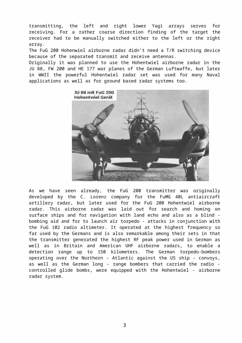
The C. Lorenz company took part of the competition with the new FuMG 40L radar set. The large parabolic antennas and the new powerful DS 323 tube transmit-ter allowed an instrumented range of 50 km. The dis-play unit was equipped with the typical German circu-lar range scope. The new CRT of 168 mm diameter with internal graticule enabled improved range accur-acy. However, the Würzburg radar set from the com-petitor Telefunken showed a clear superiority over the Lorenz device for gun laying. Even without the so called Quirl (conical scanning system antenna) the Würzburg A, demonstrated to military authorities in July 1939, proved sufficiently good to be used for fir-ing targets obscured by clouds or fog, so Lorenz ceased production of the FuMG 40L set.
In 1941 the C. Lorenz company started the prepara-tion for the development of an airborne radar set. The later designation of this set was FuG 200 Hohentwiel, it was planned to use this equipment in airplanes for search and homing on surface ships and for navigation with land echoes. For the de-velopment took the C. Lorenz company advantage from their earlier radar experi-ence on 50 cm wavelength. The RLM specification didn’t dictate that the antenna beam could be turned relative to the airplane, so scanning required turning of the plane, so the “Luftwaffe” - operational procedure intended that the airplane for search had to fly a full circle. The photo below shows the arrangement of the horizontal polarized Hohentwiel radar antennas installed on the nose of a JU 88 airplane. The upper Yagi array in the centreline of the plane serves for transmitting, the left and right lower Yagi arrays serves for receiving. For a rather coarse direction finding of the target the receiver had to be manually switched either to the left or the right array. The FuG 200 Hohenwiel airborne radar didn’t need a T/R switching device because of the separated transmit and receive antennas. Originally it was planned to use the Hohentwiel airborne radar in the JU 88, FW 200 and HE 177 war planes of the German Luftwaffe, but later in WWII the powerful Ho-hentwiel radar set was used for many Naval applications as well as for ground based radar systems too.
2
As we have seen already, the FuG 200 transmitter was originally developed by the C. Lorenz company for the FuMG 40L antiaircraft artillery radar, but later used for the FuG 200 Hohentwiel airborne radar. This airborne radar was laid out for search and homing on surface ships and for navigation with land echo and also as a blind - bombing aid and for to launch air torpedo - attacks in conjunction with the FuG 102 radio altimeter. It operated at the highest frequency so far used by the Germans and is also remarkable among their sets in that the transmitter generated the highest RF peak power used in German as well as in Britain and American UHF airborne radars, to enable a detection range up to 150 kilometers. The German torpedo-bombers op-erating over the Northern - Atlantic against the US ship - convoys, as well as the German long - range bombers that carried the radio - controlled glide bombs, were equipped with the Hohentwiel - airborne radar system.
The Hohentwiel airborne radar transmitter (shown here as open laboratory model) was derived from the DS 323 transmitter. Its push - pull grounded - grid oscillator was tuneable between 525 - 575 MHz. Two Lorenz RD12Tf triodes with oxide - cath-odes (an improved version of the DS 323 tube) were used as oscillator tubes. The transmitter was plate keyed by a thyratron modulator with 10 kV, 2 µs pulses at a pulse repetition rate of approx. 50 Hz. The photo shows on the top the plate resonant circuit, it had six plate connections per tube. One of the two tuneable cathode lines is visible in the foreground. The bot-tom of the photo shows the Lecher line for symmetric to asymmetric conversion of the RF-power by a Balun. The transmitter generates an UHF pulse power of 30 kW.
The schematic diagram of the Hohentwiel-transmitter is shown beside. Feedback voltages for the tube cathodes are pro-duced by voltage - dividing in the tube ca-pacities C plate-cathode and C grid-cathode. The ad-justable cathode line circuits provide phase control for the feed - back. The oscillator frequency is determined by the plate - cir-cuit inductance, the lumped plate - circuit capacitances and the internal gridplate ca-pacitances of the tubes. For the separation from the DC high - voltage potential, in-
ductive coupling is employed between the plate resonant circuit and the output. The UHF – output power is coupled via the tuneable Balun - transformer.
The photo shows the output circuit of the Hohentwiel - transmitter with
3
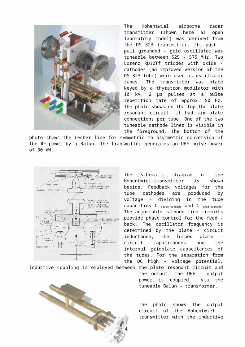
the inductive coupling loop and the tuneable balun transformer. With the adjustable stubs of the Lecher lines shown at the left of the photo the output circuit is tuned to resonance with the transmitter frequency. The adjustable slide bar at the right en-ables to match the transmitter output to the load impedance.
At the highest useful frequencies of triodes, the grid-return or grounded-grid circuitis of great importance for oscillators. The basic reason is the physical position of the grid between cathode and plate in a triode.
Grid-return oscillators can be made in which almost the only coupling between the frequency-determining plate circuit and the feedback to the cathode circuit is produced in the capacitive voltage divider formed by the internal tube capacities Cpk
(plate-cathode 1.35 - 1.65 pf ) and Cgk (grid-cathode 6.3 - 7.7pf for
the RD12Tf triode).
The resonant-transformation effect necessary to supply the feedback voltages to the cathode circuits is produced by this capacitive voltage divider, so that the polarity of the returned voltage is correct and that the required step-down voltage ratio is provided.
The RD12Tf transmitting-triode was de-veloped in 1940 at the C. Lorenz tube laboratory in Berlin, for radar applications. Like its predecessor the DS323 tube, it was fitted with an oxide cathode and was laid out for operation up to 600 MHz. Its con-struction meets the physical requirements for airborne use. As partly visible on the photo, the tube has six plate pins and three grid pins. With forced air cooling the plate dissipation rating is 75 watts. In plate-keying operation the tube may be pulsed up to 18 kV at sea level and gener-ate an RF output power in the region of 50 kW. For the Hohentwiel airborne transmit-ter a plate pulse voltage of 9 kV was ap-plied, but it was reduced above 3000 meters flight altitude, where the low pres-sure caused arcing problems.
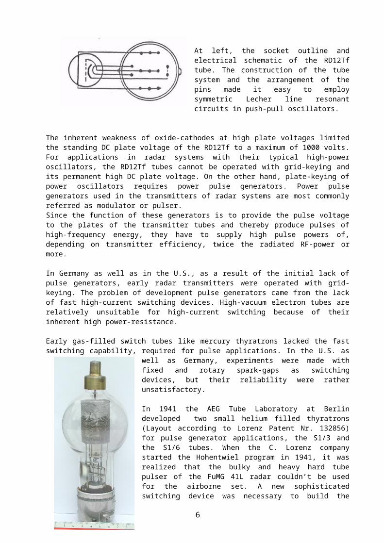
At left, the socket outline and electrical schematic of the RD12Tf tube. The con-struction of the tube system and the ar-rangement of the pins made it easy to em-ploy symmetric Lecher line resonant cir-cuits in push-pull oscillators.
The inherent weakness of oxide-cathodes at high plate voltages limited the standing DC plate voltage of the RD12Tf to a maximum of 1000 volts. For applications in radar systems with their typical high-power oscillators, the RD12Tf tubes cannot be operated with grid-keying and its permanent high DC plate voltage. On the other
4

hand, plate-keying of power oscillators requires power pulse generators. Power pulse generators used in the transmitters of radar systems are most commonly re-ferred as modulator or pulser. Since the function of these generators is to provide the pulse voltage to the plates of the transmitter tubes and thereby produce pulses of high-frequency energy, they have to supply high pulse powers of, depending on transmitter efficiency, twice the radiated RF-power or more.
In Germany as well as in the U.S., as a result of the initial lack of pulse generators, early radar transmitters were operated with grid-keying. The problem of develop-ment pulse generators came from the lack of fast high-current switching devices. High-vacuum electron tubes are relatively unsuitable for high-current switching be-cause of their inherent high power-resistance.
Early gas-filled switch tubes like mercury thyratrons lacked the fast switching capab-ility, required for pulse applications. In the U.S. as well as Germany, experiments were made with fixed and rotary spark-gaps as switching devices, but their reliabil-ity were rather unsatisfactory.
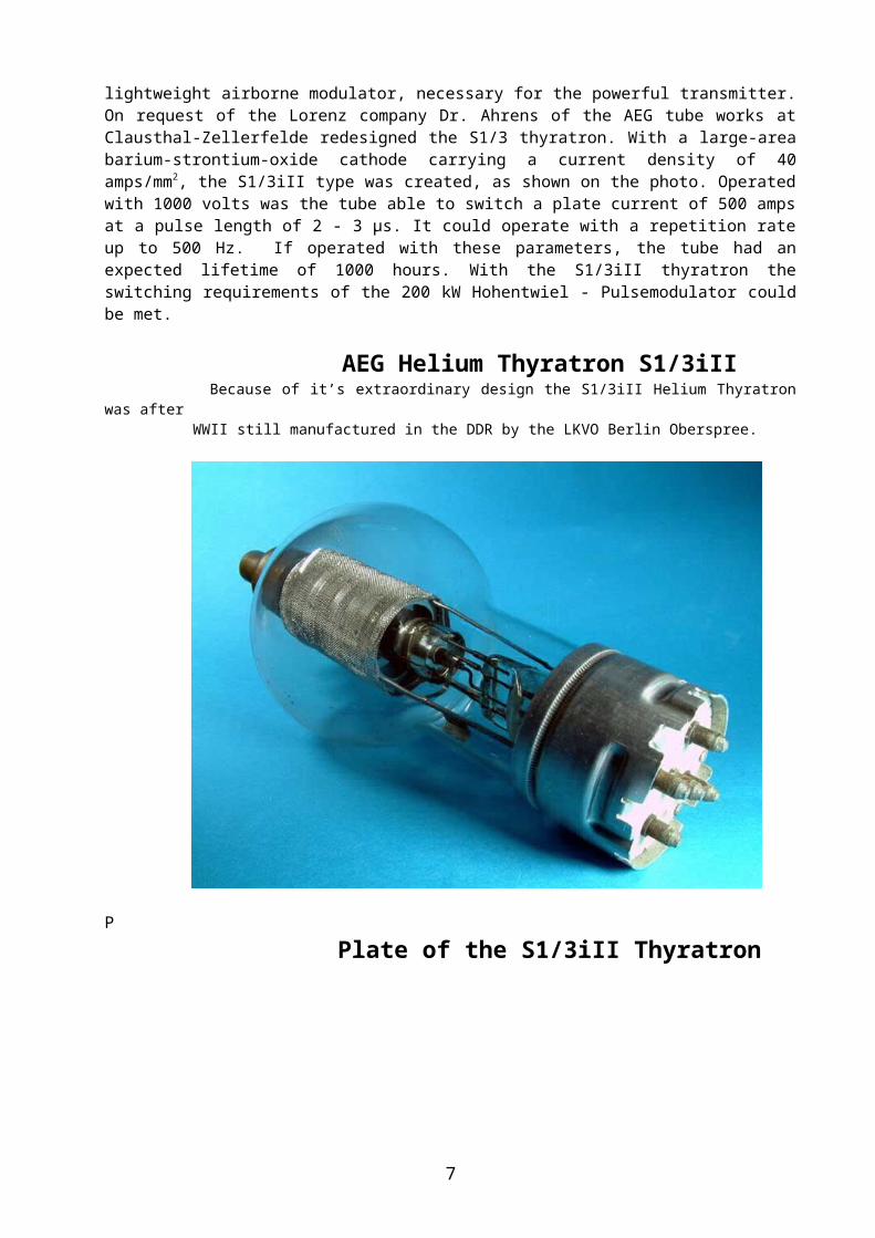
In 1941 the AEG Tube Laboratory at Berlin developed two small helium filled thyratrons (Layout according to Lorenz Patent Nr. 132856) for pulse generator applica-tions, the S1/3 and the S1/6 tubes. When the C. Lorenz company started the Hohentwiel program in 1941, it was realized that the bulky and heavy hard tube pulser of the FuMG 41L radar couldn’t be used for the airborne set. A new sophisticated switching device was necessary to build the lightweight airborne modulator, necessary for the powerful transmitter. On request of the Lorenz com-pany Dr. Ahrens of the AEG tube works at Clausthal-Zellerfelde redesigned the S1/3 thyratron. With a large-area barium-strontium-oxide cathode carrying a current density of 40 amps/mm2, the S1/3iII type was created, as shown on the photo. Operated with 1000 volts was the tube able to switch a plate current of 500 amps at a pulse length of 2 - 3 µs. It could operate with a repetition rate up to 500 Hz. If operated with these parameters, the tube had an expected lifetime of 1000 hours. With the S1/3iII thyratron the switching requirements of the 200 kW Hohentwiel - Pulsemodulator could be met.
AEG Helium Thyratron S1/3iII Because of it’s extraordinary design the S1/3iII Helium Thyratron was after WWII still manufactured in the DDR by the LKVO Berlin Oberspree.
5
P
Plate of the S1/3iII Thyratron
6
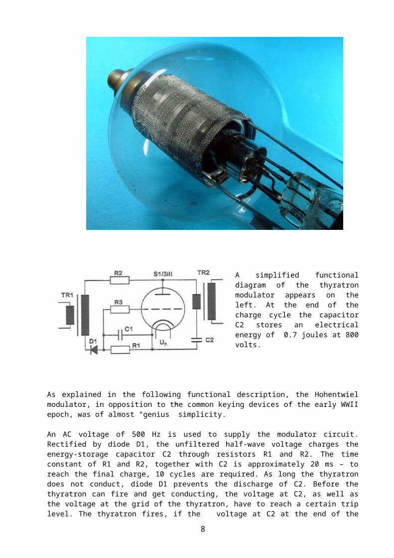
A simplified functional diagram of the thyratron modulator appears on the left. At the end of the charge cycle the capacitor C2 stores an electrical energy of 0.7 joules at 800 volts.
As explained in the following functional description, the Ho-
hentwiel modulator, in opposition to the common keying devices of the early WWII epoch, was of almost “genius” simplicity.
An AC voltage of 500 Hz is used to supply the modulator circuit. Rectified by diode D1, the unfiltered half-wave voltage charges the energy-storage capacitor C2 through resistors R1 and R2. The time constant of R1 and R2, together with C2 is ap-proximately 20 ms – to reach the final charge, 10 cycles are required. As long the thyratron does not conduct, diode D1 prevents the discharge of C2. Before the thyratron can fire and get conducting, the voltage at C2, as well as the voltage at the grid of the thyratron, have to reach a certain trip level. The thyratron fires, if the voltage at C2 at the end of the charge cycle has reached approx. 800 volts and if the grid voltage gets more positive than –10 volts. The initial high charging current of C2 causes a high voltage drop at R1 and charges capacitor C1 to a relatively high negative voltage, which is applied to the grid of the thyratron. The time constant of R-C circuit R1 - C1 is calculated such that the decreasing charging current of C2 does not compensate for its discharge. Therefore the negative voltage at the grid of the thyratron decreases slowly over the 500 Hz cycles. At the tenth have-wave cycle, the thyratron fires. This causes an instant discharge of the energy-storage ca-pacitor C2 into the primary winding of the pulse transformer TR2 and induces a short but high voltage pulse in the secondary winding. TR2 has a turn ratio of 1:24; it provides voltage and impedance transformation between the modulator and the transmitter. The modulator circuit is dividing-down the 500 Hz half-wave cycles into the repetition rate of 50 Hz for keying the transmitter tubes with 10 kV, 2 µs pulses.
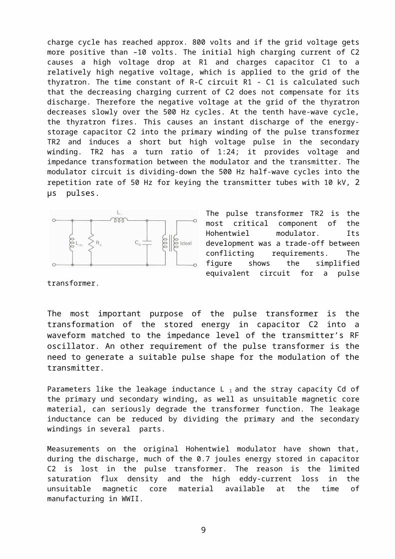
The pulse transformer TR2 is the most critical component of the Hohentwiel modulator. Its development was a trade-off between conflicting requirements. The figure shows the simplified equivalent cir-cuit for a pulse transformer.
The most important purpose of the pulse transformer is the transformation of the stored energy in capacitor C2 into a waveform matched to the impedance level of the transmitter’s RF oscillator. An other requirement of the pulse transformer is the need to generate a suitable pulse shape for the modulation of the transmitter.
Parameters like the leakage inductance L l and the stray capacity Cd of the primary und secondary winding, as well as unsuitable magnetic core material, can seriously degrade the transformer function. The leakage inductance can be reduced by divid-ing the primary and the secondary windings in several parts.
7
Measurements on the original Hohentwiel modulator have shown that, during the discharge, much of the 0.7 joules energy stored in capacitor C2 is lost in the pulse transformer. The reason is the limited saturation flux density and the high eddy-cur-rent loss in the unsuitable magnetic core material available at the time of manufac-turing in WWII.
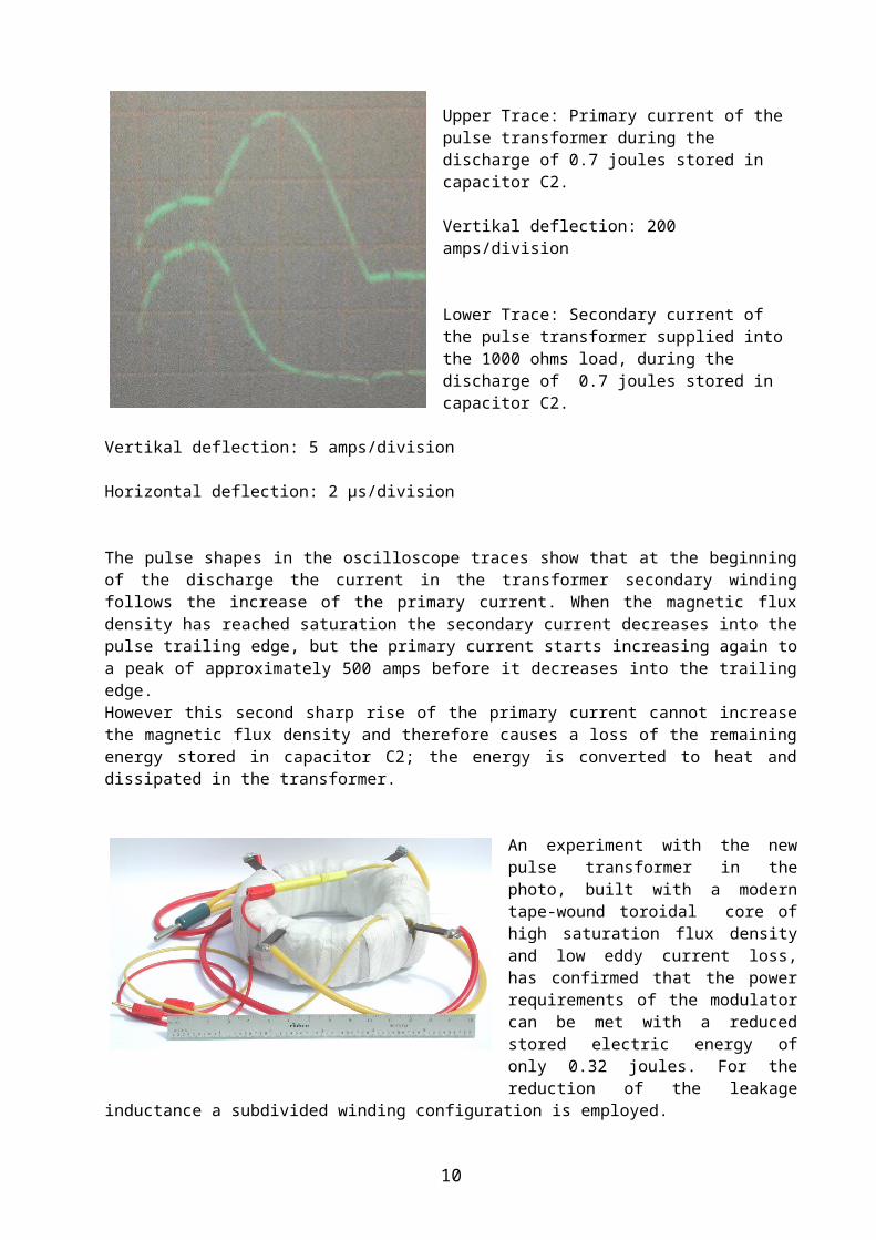
Upper Trace: Primary current of the pulse transformer during the discharge of 0.7 joules stored in capacitor C2. Vertikal deflection: 200 amps/division
Lower Trace: Secondary current of the pulse transformer supplied into the 1000 ohms load, during the discharge of 0.7 joules stored in capacitor C2. Vertikal deflection: 5 amps/division
Horizontal deflection: 2 µs/division
The pulse shapes in the oscilloscope traces show that at the beginning of the dis-charge the current in the transformer secondary winding follows the increase of the primary current. When the magnetic flux density has reached saturation the second-ary current decreases into the pulse trailing edge, but the primary current starts in-creasing again to a peak of approximately 500 amps before it decreases into the trailing edge. However this second sharp rise of the primary current cannot increase the magnetic flux density and therefore causes a loss of the remaining energy stored in capacitor C2; the energy is converted to heat and dissipated in the transformer.
An experiment with the new pulse transformer in the photo, built with a modern tape-wound toroidal core of high saturation flux density and low eddy current loss, has con-firmed that the power require-ments of the modulator can be met with a reduced stored electric en-ergy of only 0.32 joules. For the re-duction of the leakage inductance a subdivided winding configuration is employed.
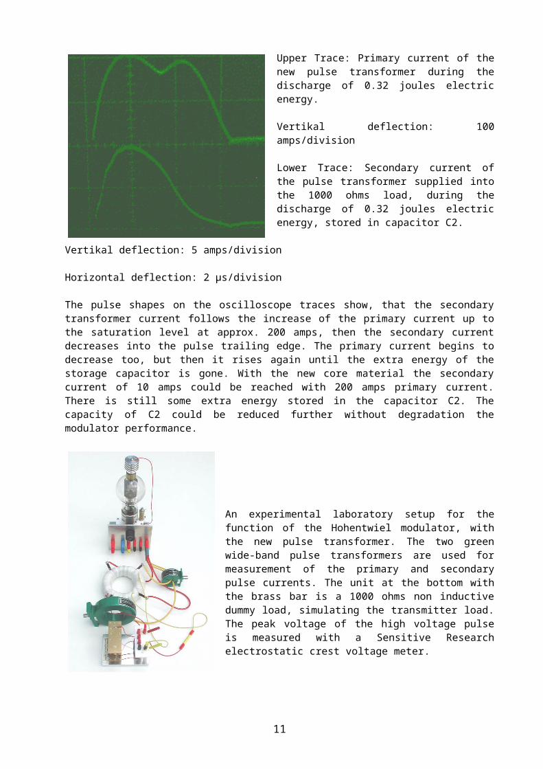
Upper Trace: Primary current of the new pulse transformer during the discharge of 0.32 joules electric energy. Vertikal deflection: 100 amps/division
8
Lower Trace: Secondary current of the pulse transformer supplied into the 1000 ohms load, during the discharge of 0.32 joules electric energy, stored in capacitor C2.
Vertikal deflection: 5 amps/division
Horizontal deflection: 2 µs/division
The pulse shapes on the oscilloscope traces show, that the secondary transformer current follows the increase of the primary current up to the saturation level at ap-prox. 200 amps, then the secondary current decreases into the pulse trailing edge. The primary current begins to decrease too, but then it rises again until the extra energy of the storage capacitor is gone. With the new core material the secondary current of 10 amps could be reached with 200 amps primary current. There is still some extra energy stored in the capacitor C2. The capacity of C2 could be reduced further without degradation the modulator performance.
An experimental laboratory setup for the function of the Hohentwiel modulator, with the new pulse trans-former. The two green wide-band pulse transformers are used for measurement of the primary and sec-ondary pulse currents. The unit at the bottom with the brass bar is a 1000 ohms non inductive dummy load, simulating the transmitter load. The peak voltage of the high voltage pulse is measured with a Sensitive Research electrostatic crest voltage meter.
Project: Transmitter RF Peak-Power Measure-ment
Studies of reports published by the CIOS and BIOS teams about their investigations in German industrial and government laboratories at the end of WWII as well as doc-umentation of the U.S. National Bureau of Standards, have shown that procedures for accurate RF peak power measurements at UHF or microwave frequencies did not exist, neither in Germany nor in the U.S. at the time of WWII. So RF peak pulse power measurements on early UHF radars were a rather difficult ventures. Surprisingly, however, the government laboratories and industrial companies, as well as the military agencies, specified this parameter with tight tolerances, al-though neither standard methods nor accurate test equipments were available in those days. The original technical specifications for the equipments found their way into the post-war literature, probably without further verification in most cases. The presumption is therefore obvious, that many of the specified RF peak power values were rather unreliable and probably to optimistic.
Various methods for RF peak-power measurements at UHF and microwave frequen-cies have been developed and standardized over the past fifty years.
9
In general, the aim has been to develop instruments which indicate the measured quantity directly. Indirect methods such as calculation of the pulse power from the average power are limited in accuracy, because they are strongly influenced by changes in the duty cycle caused by pulse shape fluctuations, etc. It seems there-fore worthwhile and interesting to measure the RF peak pulse power of the Ho-hentwiel radar transmitter with present-day instrumentation, as long as several in-dependent sets of transmitting tubes are available in good conditions.
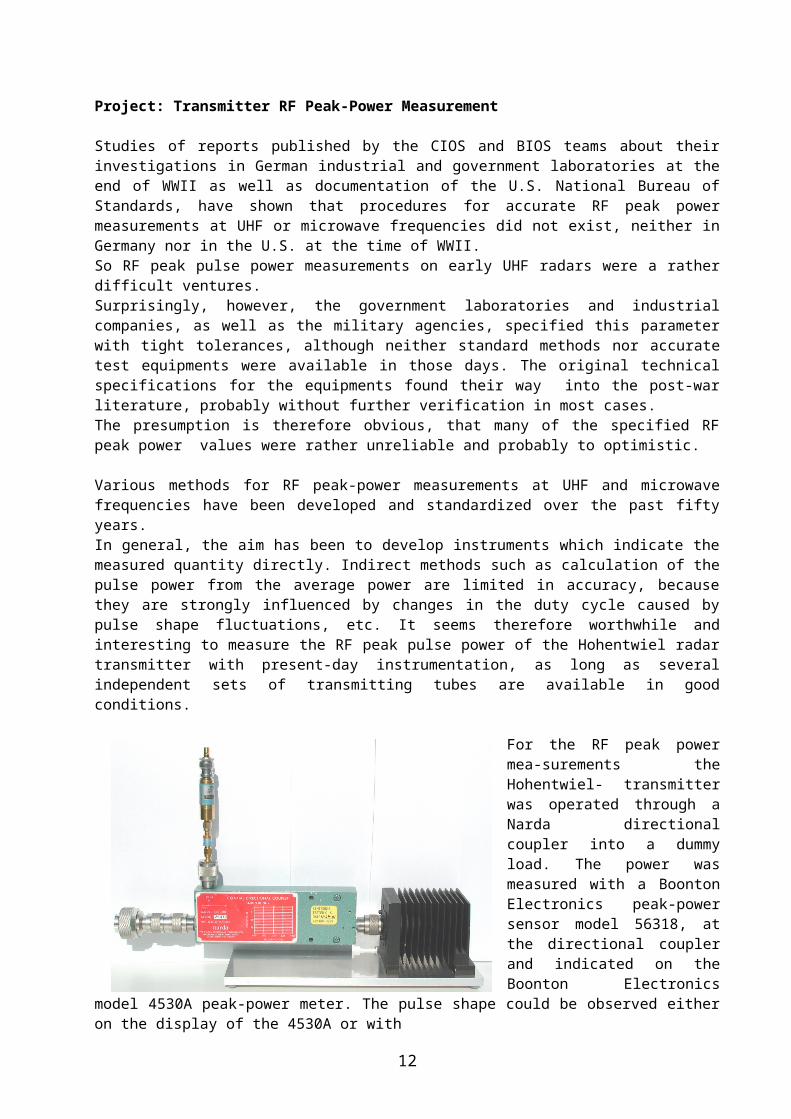
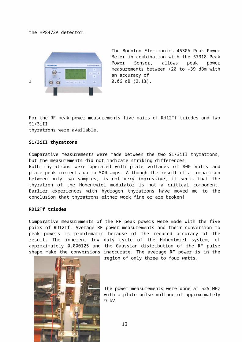
For the RF peak power mea-surements the Hohentwiel- transmitter was operated through a Narda directional coupler into a dummy load. The power was measured with a Boonton Electronics peak-power sensor model 56318, at the directional coupler and indicated on the Boonton Electronics model 4530A peak-power meter. The pulse shape could be observed either on the dis-play of the 4530A or with
the HP8472A detector.
The Boonton Electronics 4530A Peak Power Meter in combination with the 57318 Peak Power Sensor, allows peak power measure-ments between +20 to -39 dBm with an accur-acy of
± 0.06 dB (2.1%).
For the RF-peak power measurements five pairs of Rd12Tf triodes and two S1/3iIIthyratrons were available.
S1/3iII thyratrons
Comparative measurements were made between the two S1/3iII thyratrons, but the measurements did not indicate striking differences.Both thyratrons were operated with plate voltages of 800 volts and plate peak cur-rents up to 500 amps. Although the result of a comparison between only two samples, is not very impressive, it seems that the thyratron of the Hohentwiel modu-lator is not a critical component. Earlier experiences with hydrogen thyratrons have moved me to the conclusion that thyratrons either work fine or are broken!
RD12Tf triodes
Comparative measurements of the RF peak powers were made with the five pairs of RD12Tf. Average RF power measurements and their conversion to peak powers is problematic because of the reduced accuracy of the result. The inherent low duty
10
cycle of the Hohentwiel system, of approximately 0.000125 and the Gaussian distri-bution of the RF pulse shape make the conversions inaccurate. The average RF power is in the region of only three to four watts.
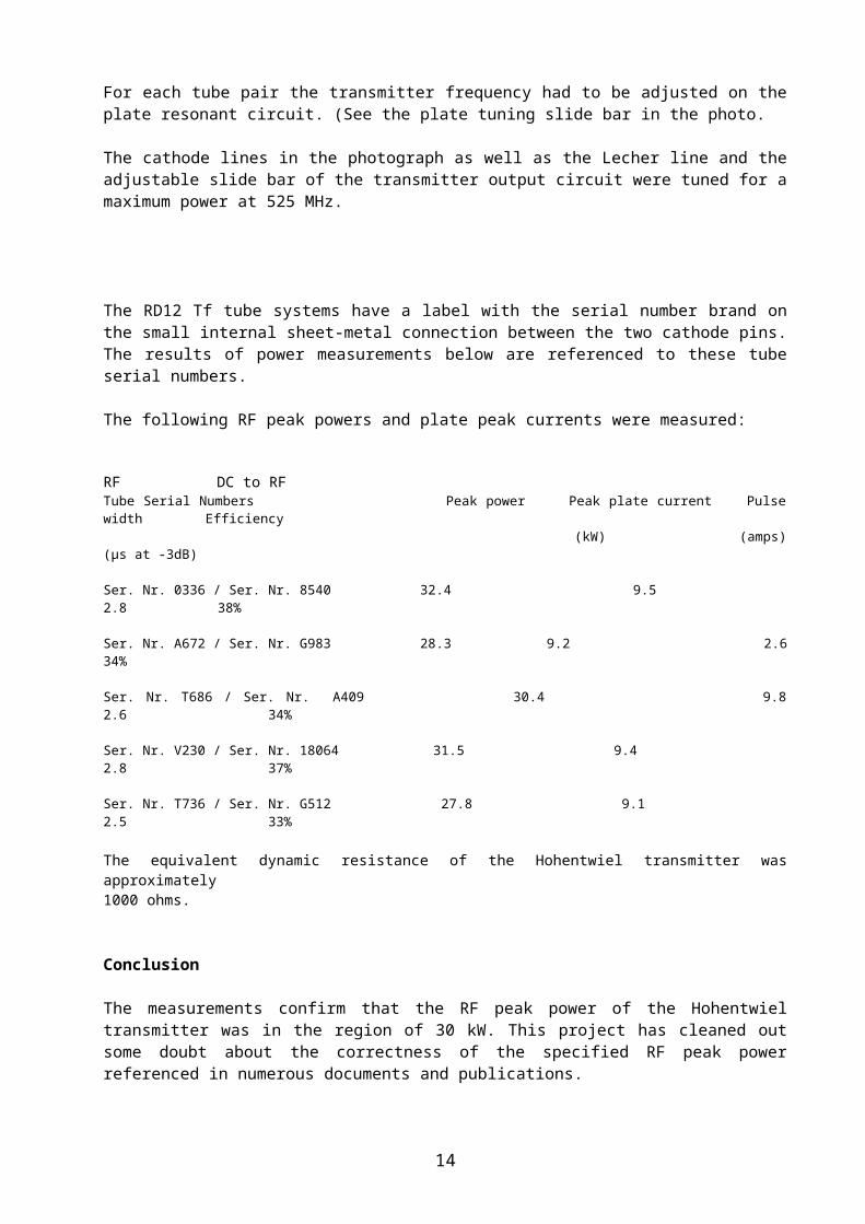
The power measurements were done at 525 MHz with a plate pulse voltage of approximately 9 kV.
For each tube pair the transmitter frequency had to be adjusted on the plate resonant circuit. (See the plate tuning slide bar in the photo.
The cathode lines in the photograph as well as the Lecher line and the adjustable slide bar of the transmitter output circuit were tuned for a max-imum power at 525 MHz.
The RD12 Tf tube systems have a label with the serial number brand on the small in-ternal sheet-metal connection between the two cathode pins. The results of power measurements below are referenced to these tube serial numbers.
The following RF peak powers and plate peak currents were measured:
RF DC to RFTube Serial Numbers Peak power Peak plate current Pulse width Efficiency (kW) (amps) (µs at -3dB)
Ser. Nr. 0336 / Ser. Nr. 8540 32.4 9.5 2.8 38%
Ser. Nr. A672 / Ser. Nr. G983 28.3 9.2 2.6 34%
Ser. Nr. T686 / Ser. Nr. A409 30.4 9.8 2.6 34%
Ser. Nr. V230 / Ser. Nr. 18064 31.5 9.4 2.8 37%
Ser. Nr. T736 / Ser. Nr. G512 27.8 9.1 2.5 33%
The equivalent dynamic resistance of the Hohentwiel transmitter was approximately 1000 ohms.
Conclusion
The measurements confirm that the RF peak power of the Hohentwiel transmitter was in the region of 30 kW. This project has cleaned out some doubt about the cor-rectness of the specified RF peak power referenced in numerous documents and publications.
Hohentwiel-Equipment with common transmit/receive antenna
A modified version of the Hohentwiel equipment with a common rotatable transmit/receive antenna array came in use later in WWII for the U-boats of the German Navy. For the separation of the transmit and receive path a T/R switch device was
11
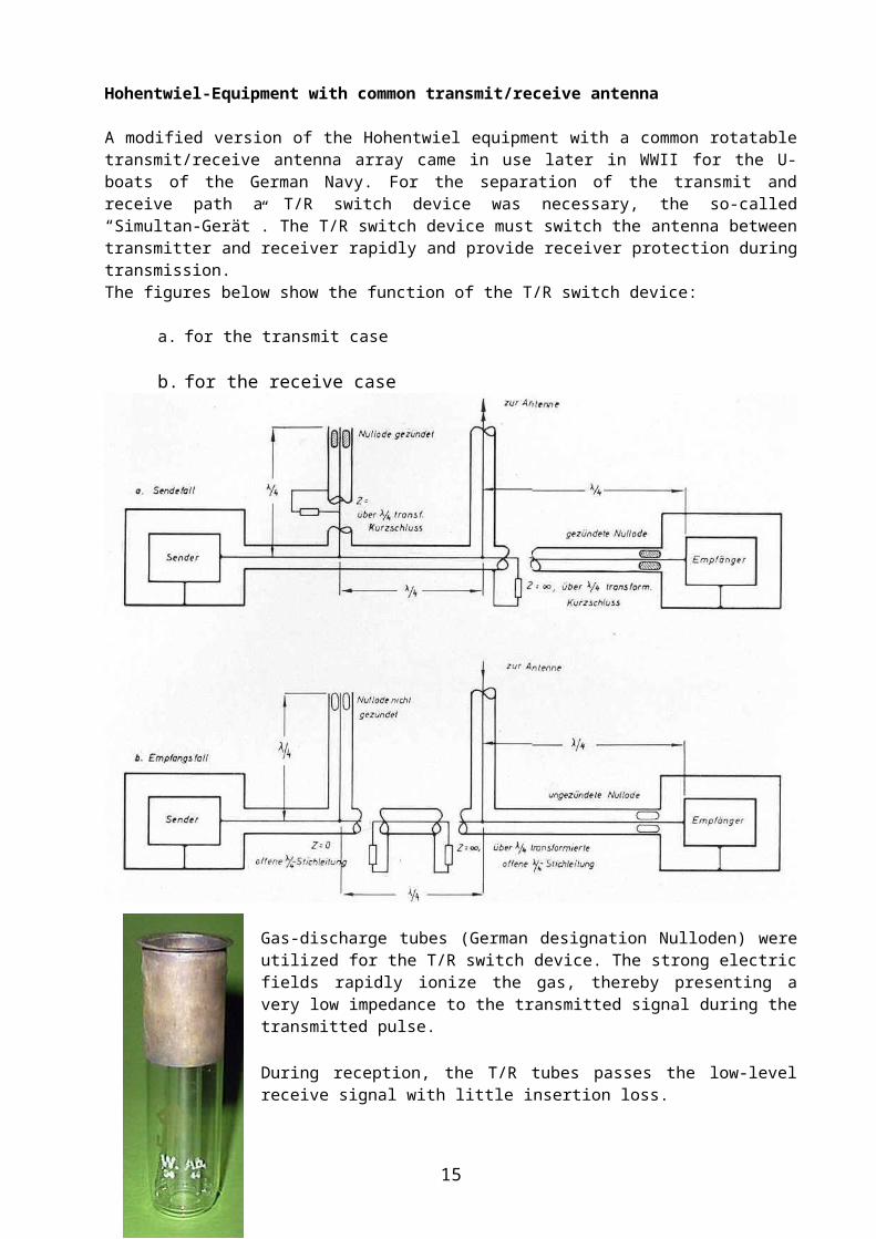
necessary, the so-called “Simultan-Gerät”. The T/R switch device must switch the antenna between transmitter and receiver rapidly and provide receiver protection during transmission.The figures below show the function of the T/R switch device:
a. for the transmit case
b. for the receive case
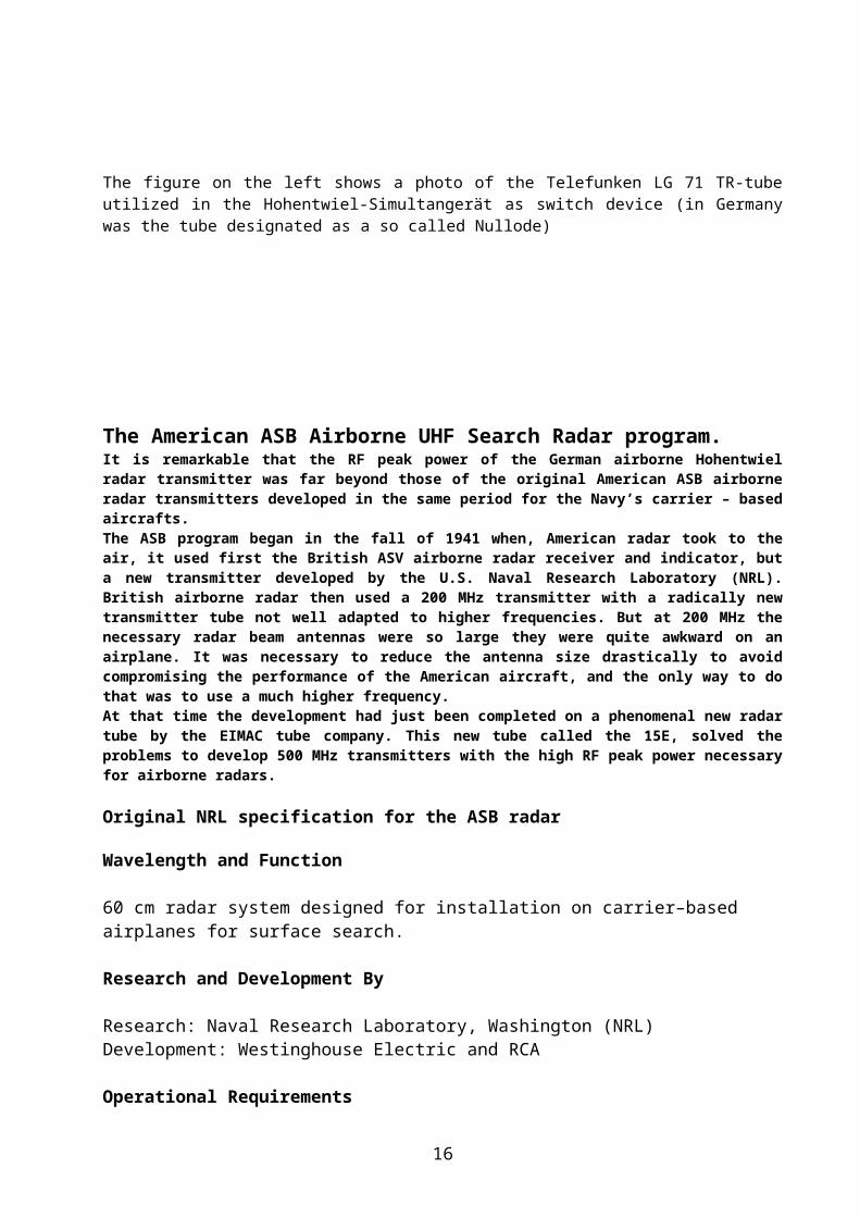
Gas-discharge tubes (German designation Nulloden) were utilized for the T/R switch device. The strong electric fields rapidly ionize the gas, thereby presenting a very low impedance to the transmitted signal during the transmitted pulse.
During reception, the T/R tubes passes the low-level receive signal with little inser-tion loss.
The figure on the left shows a photo of the Telefunken LG 71 TR-tube utilized in the Hohentwiel-Simultangerät as switch device (in Germany was the tube designated as a so called Nullode)
12
The American ASB Airborne UHF Search Radar program.It is remarkable that the RF peak power of the German airborne Hohentwiel radar transmitter was far beyond those of the original American ASB airborne radar transmitters developed in the same period for the Navy’s carrier – based aircrafts.The ASB program began in the fall of 1941 when, American radar took to the air, it used first the British ASV airborne radar receiver and indicator, but a new trans-mitter developed by the U.S. Naval Research Laboratory (NRL). British airborne radar then used a 200 MHz transmitter with a radically new transmitter tube not well adapted to higher frequencies. But at 200 MHz the necessary radar beam an-tennas were so large they were quite awkward on an airplane. It was necessary to reduce the antenna size drastically to avoid compromising the performance of the American aircraft, and the only way to do that was to use a much higher fre-quency.At that time the development had just been completed on a phenomenal new radar tube by the EIMAC tube company. This new tube called the 15E, solved the problems to develop 500 MHz transmitters with the high RF peak power necessary for airborne radars.
Original NRL specification for the ASB radar
Wavelength and Function
60 cm radar system designed for installation on carrier–based airplanes for surface search.
Research and Development By
Research: Naval Research Laboratory, Washington (NRL)Development: Westinghouse Electric and RCA
Operational Requirements
Weight 120 lbPower Supply 345 watts, 115 volts 1 phase, 600 – 1400 HzPerformance
Max. Reliable Range on:Bombers, at 10’000 ft 6 mi.Battleships 40 mi.Heavy Cruisers 40 mi.Destroyers 30 mi.Submarines (surfaced) 5 mi.Cargo vessels 10’000 t. 40 mi.
Minimum Range: 500 yd.Range Accuracy: ± 5 %Angular Accuracy: Azimuth: ± 1°
Search
13
Identical antennas mounted on each wing have 60° wide lobes in azimuth. Antenna can be rotated individually through 90° by operator. In searching over open water, the antennas are oriented so that the lobes from the two antennas are perpendicular to the line of flight. In homing, the lobes point es-sentially parallel to the line of flight.
Antenna Specification
Identical dipole arrays are mounted on each wing, only one antenna at a time being used.The antennas are switched at a rate of 1800 Hz. Each array has a beam width of 60° in azimuth and a gain of 14.7 dB. The antennas can be turned individu-ally so that the beam from either one points in any direction betweenthe lim-its of 90° to the line of flights and essentially parallel the limits of 90° to the line of flight and essentially parallel to it.
Transmitter Specification
Engineering problems involved in the design of the ASB airborne radar trans-mitter as well as changes in tactical and operational requirements caused the necessity of making several versions of transmitters.
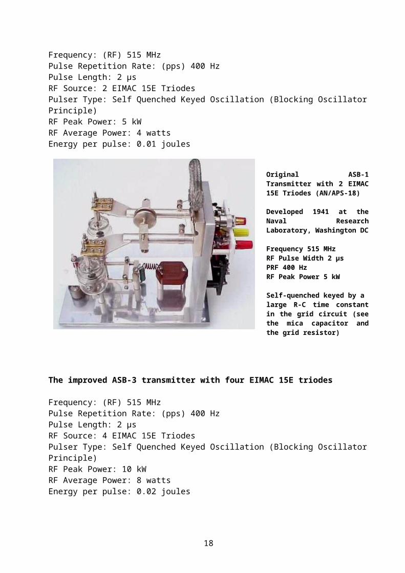
The ASB-1 transmitter with two EIMAC 15E triodes Frequency: (RF) 515 MHzPulse Repetition Rate: (pps) 400 HzPulse Length: 2 µsRF Source: 2 EIMAC 15E TriodesPulser Type: Self Quenched Keyed Oscillation (Blocking Oscillator Principle)RF Peak Power: 5 kWRF Average Power: 4 wattsEnergy per pulse: 0.01 joules
Original ASB-1 Transmit-ter with 2 EIMAC 15E Tri-odes (AN/APS-18)
Developed 1941 at the Naval Research Laborat-ory, Washington DC
Frequency 515 MHzRF Pulse Width 2 µsPRF 400 HzRF Peak Power 5 kW
Self-quenched keyed by alarge R-C time constant in the grid circuit (see the mica capacitor and the grid resistor)
14
The improved ASB-3 transmitter with four EIMAC 15E triodes Frequency: (RF) 515 MHzPulse Repetition Rate: (pps) 400 HzPulse Length: 2 µsRF Source: 4 EIMAC 15E TriodesPulser Type: Self Quenched Keyed Oscillation (Blocking Oscillator Principle)RF Peak Power: 10 kWRF Average Power: 8 wattsEnergy per pulse: 0.02 joules
Improved ASB-3 Transmitter with 4 EIMAC 15E Triodes
Developed 1941 at the Naval Research Laboratory, Washington DC
Frequency 515 MHzRF Pulse Width 2 µsPRF 400 HzRF Peak Power 10 kW
Self - quenched keyed by a large R-C time constant in the grid circuit (mica capacitor and grid resistor on the out-side of the housing)
The improved ASB-7 transmitter with six EIMAC 15E triodes Frequency: (RF) tunable 515 – 530 MHzPulse Repetition Rate: (pps) 400 HzPulse Length: 2 µsRF Source: Ring circuit oscillator with 6 EIMAC 15E Triodes The Ring Circuit Oscillator principle was a typically NRL design to increase the RF output power of the early VHF and UHF radar transmitters, it was first proposed by the NRL expert Robert Morris Page on 1941. It was not limited to four tubes, it only is necessary that the number of tubes be even. As the number of tubes is increased, however the difficulties with matching of the tube parameters and the alignments of the ring circuitry arise. It was foundthat six tubes were very stable.
Pulser Type: High power plate pulsed wide band transmitterRF Peak Power: 50 kWRF Average Power: 8 wattsEnergy per pulse: 0.1 joules
Improved ASB-7 Transmitter with sixEIMAC 15E Triodes (ASB 7 transmitter)
15
Developed 1944 at the Naval Research Laboratory, Washington DC
Frequency tunable 515 – 530 MHz RF Pulsewidth 2 µsPRF 400 HzRF Peak Power 50 kW
High Power Plate Pulsed Wide Band transmitter with a separate pulse modulator unit.
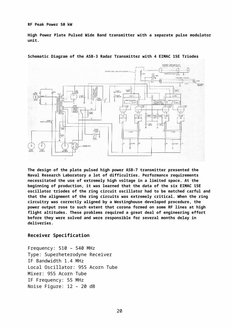
Schematic Diagram of the ASB-3 Radar Transmitter with 4 EIMAC 15E Triodes
The design of the plate pulsed high power ASB-7 transmitter presented the Naval Research Laboratory a lot of difficulties. Performance requirements necessitated the use of extremely high voltage in a limited space. At the beginning of produc-tion, it was learned that the data of the six EIMAC 15E oscillator triodes of the ring circuit oscillator had to be matched carful and that the alignment of the ring cir-cuits was extremely critical. When the ring circuitry was correctly aligned by a Westinghouse developed procedure, the power output rose to such extent that corona formed on some RF lines at high flight altitudes. These problems required a great deal of engineering effort before they were solved and were responsible for several months delay in deliveries. Receiver Specification
Frequency: 510 – 540 MHzType: Superheterodyne ReceiverIF Bandwidth 1.4 MHzLocal Oscillator: 955 Acorn TubeMixer: 955 Acorn Tube IF Frequency: 55 MHzNoise Figure: 12 – 20 dB
The classical description of the superheterodyne receiver includes an RF amplifier at the front end. At uhf frequencies, however, an RF amplifier was
16

not always used. The original ASB radar receivers operated with the mixer as the first stage of the receiver.
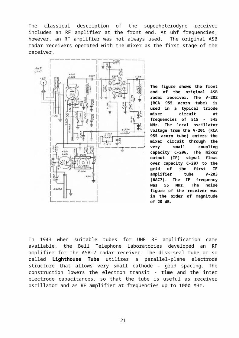
The figure shows the front end of the original ASB radar receiver. The V-202 (RCA 955 acorn tube) is used in a typ-ical triode mixer circuit at frequencies of 515 – 545 MHz. The local oscillator voltage from the V-201 (RCA 955 acorn tube) enters the mixer circuit through the very small coupling capacity C-206. The mixer output (IF) signal flows over capacity C-207 to the grid of the first IF amplifier tube V-203 (6AC7). The IF frequency was 55 MHz. The noise figure of the receiver was in the order of magnitude of 20 dB.
In 1943 when suitable tubes for UHF RF ampli-fication came available, the Bell Telephone Laboratories developed an RF amplifier for the ASB-7 radar receiver. The disk-seal tube or so called Lighthouse Tube utilizes a parallel-plane electrode struc-ture that allows very small cathode - grid spa-cing. The construction lowers the electron transit - time and the inter electrode capacit-ances, so that the tube is useful as receiver os-cillator and as RF ampli-fier at frequencies up to 1000 MHz.
17
The figure shows the front end of the improved ASB-7B radar receiver. The front end consists of a single stage of RF amplifier, a local oscillator, and a mixer. Light-house tube type 446A and coaxial-line resonators are employed in the RF amplifier and mixer unit. In the local oscillator a Lighthouse tube 446A is employed too, but the resonator is of the parallel line type. The local oscillator is tuned by a variable disk capacitance at the plate-line. The connections between units are made by short sections of coaxial cable. Power coupled from the grid line of the local oscil-lator is applied together with echo signals from the RF amplifier, to the grid circuit of the triode mixer. A component of the difference frequency is produced at the plate circuit of the mixer and feed into the IF amplifier.
The noise figure of the ASB-7B radar receiver with the lighthouse RF-amplifier was approx. 12 dB.
Complete Schematic diagram of the ASB-1 Receiver
Complete Schematic diagram of the ASB-7 Receiver
18

Indication and Data Output
5 inches CRT used with vertical sweep from bottom to top along a diameter of the screen. Signals from the port antenna produce horizontal pips to the left while those from the starboard antenna produce horizontal pips to the right. Ranges 7, 28, and 70 Nautical Miles; some sets have 2 miles sweep cal-ibrated only at 1000 yards. The ASB-7A had improved indicator with 5000 yards, 15, 50 and 150 Nautical Mile ranges and provisions for the laboratory.
The 15E UHF triode was developed in 1940 at the Eitel-McCullough company San Bruno CA for pulse os-cillator applications. The 15E has a direct heated thoriated tungsten fila-ment. The plate dissipation of the tube is 20 watts and it can be operated up to a maximum plate voltage of 12.5 kV. The 15E tubes were used by the U.S. Navy in various grounded-plate oscillators at fre-quencies between 400 and 600 MHz. These early pulse type oscillators were typically self-quenched
keyed employing large R-C time constants in the grid circuits.
19
Tubes with oxide coated cathodes like the RD12Tf have an inherent higher pulsed emission density (mA/cm2) than tubes with thoriated tungsten filaments. So transmitters equipped with oxide cathode tubes were able to generate a higher RF peak power with the same plate voltage, but on the other hand they had to be keyed on the plate and required power pulse modulators. Comparative measurements of the cathode emissions were done with a number of 15E’s and RD12Tf’s triodes.
The 15E’s with the thoriated tungsten filament were operated with 5.5 volts. The 15E’s showed pulsed fil-ament emissions in the region of 4 amperes at 6 kV. For the measurements the tubes were operated with a plate - grid connection as diode. The photo shows a 15E, with a plate heat dissipating connector, occa-sionally the filament emission measurement. The RD12TF’s with the oxide cathodes were oper-ated at the highest filament voltage of 14.4 volts, al-lowed, so far for pulse operation. They showed cath-ode emissions in the region of 10 amperes at 6 kV.
In retrospect it may be pointed out that the develop-ment of the oxide cathode transmitting tube DS 323 was very advanced in 1937, as well as the development of the S1/3iII Helium thyratron for the pulse modulator of the FuG 200 Hohentwiel radar set in 1941.
In Britain even for the development of the pulsed microwave radar magnetron on 1940, the application of oxide cathodes was an absolute prerequisite to meet the RF power requirements.
In the United States the thyratron application for radar pulse modulators came not in use before the end of WWII. The development of the Hydrogen thyratron began 1941 under Kenneth J. Germeshausen, but it was delayed by problems with the gas contamination and the gas clean - up in the tube. After WWII founded Kenneth J. Germeshausen together with Harold E. Edgerton and Herbert E. Grier the EG&G company, EG&G is one of the largest supplier for Hydrogen thyratrons.Acknowledgment
This project could not have been undertaken without the support of Ed Willi, Günther Hütter, Günther Riedl, Dieter Beikirch and Arthur Bauer. The author wish to thank these Gentlemen for providing some authentic key components, documentations and much advice.
References Müller G. Funkmessgeräte Entwicklung bei C. Lorenz AG, 1935 – 1945, Firmeninternes Archivheft der SEL, 2. Erweiterte Fassung, Dezember 1981
RLM Werkschrift 4108, Bordfunkmessgerät FuG 200, G. Kdos. August 1943
20
RLM Vorschrift Nr. 75/790, Prüffibel für Bordfunkmessgerät FuG 200, Oktober 1944
RLM Luftfahrtsröhren Ringbuch, Daten und Richtlinien über die Verwendung vonLuftfahrtsröhren, Januar 1945
Dr. Steimel K. Bericht über den Zustand der Röhrentechnik in Deutschland zum Abschluss des Krieges, August 1945
U.S. Air Material Command Dayton OH, Summary Report No. F-SU-1109-ND, The High Frequency War - A survey of German Electronic War, 10th May 1946
CIOS Final Report 1746, German development of modulator valves for radar applic-ations
CIOS report XXX-36, Physikalisch-Technische Reichsanstalt, June 1945
CIOS Report XXVII-46, Design of Radar Test Equipment at Siemens-Halske Munich
BIOS Report 1228, HF Instruments & Measuring Techniques
Achievement in Radio, Radio Science, Technology, Standards and Measurements at the National Bureau of Standards, US Department of Commerce, October 1986
Megla Gerhard, Dezimeterwellentechnik, Kapitel Messgeräte und Messmethoden bei Dezimeterwellen, Fachbuchverlag Leipzig, 1952
Radio Measurements, Proceedings of the IEEE, Volume 55, June 1967
Hewlett Packard, Microwave Measurement Handbook, Chapter RF Peak Power Meas-urement, Procedures and Equipments
Boonton Electronics Company, Application Note AN-50, Measuring the Peak Power
U.S. Naval Research Laboratory, ASB Radar Alignment Procedure, November 1942
21