Embed Size (px)
Citation preview
IEEE New Hampshire SectionRadar Systems Course 1Airborne PD 1/1/2010 IEEE AES Society
Radar Systems Engineering Lecture 14
Airborne Pulse Doppler Radar
Dr. Robert M. O’DonnellIEEE New Hampshire Section
Guest Lecturer
Radar Systems Course 2Airborne PD 1/1/2010
IEEE New Hampshire SectionIEEE AES Society
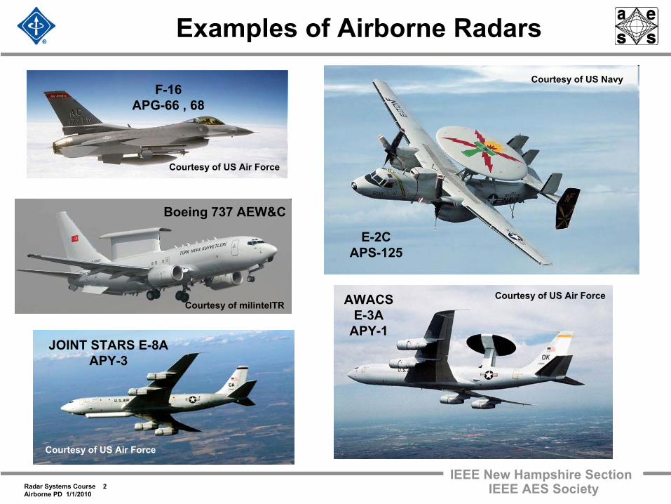
Examples of Airborne Radars
Courtesy of US Air ForceAWACSE-3A
APY-1
F-16APG-66 , 68
E-2CAPS-125
Courtesy of US Navy
JOINT STARS E-8AAPY-3
Courtesy of US Air Force
Courtesy of US Air Force
Courtesy of milintelTR
Boeing 737 AEW&C
Radar Systems Course 3Airborne PD 1/1/2010
IEEE New Hampshire SectionIEEE AES Society
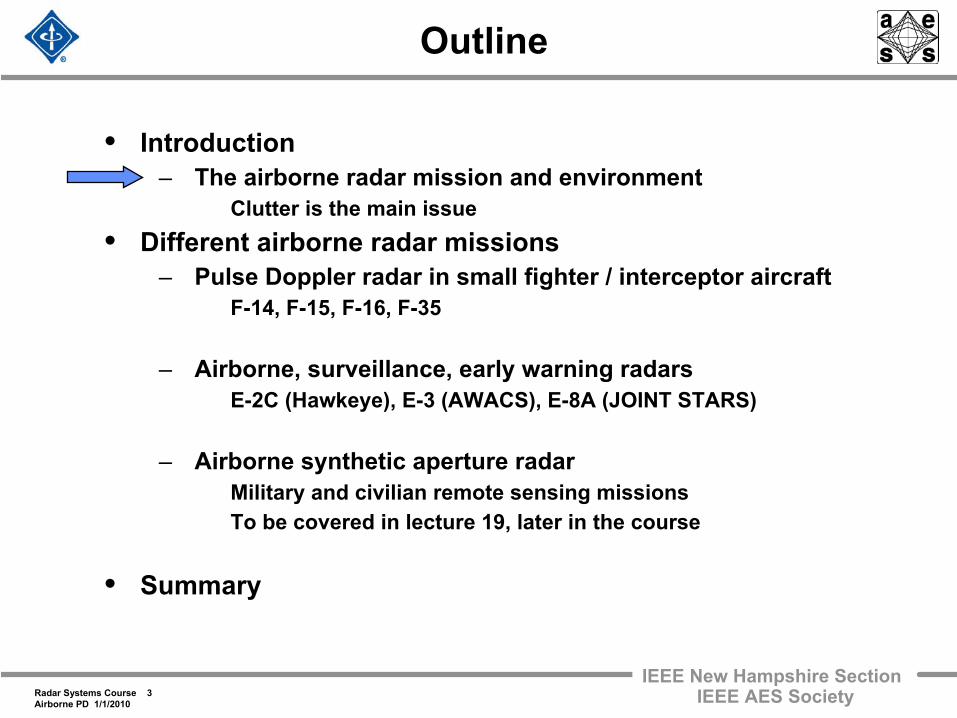
Outline
• Introduction– The airborne radar mission and environment
Clutter is the main issue• Different airborne radar missions
– Pulse Doppler radar in small fighter / interceptor aircraft F-14, F-15, F-16, F-35
– Airborne, surveillance, early warning radars E-2C (Hawkeye), E-3 (AWACS), E-8A (JOINT STARS)
– Airborne synthetic aperture radar Military and civilian remote sensing missions To be covered in lecture 19, later in the course
• Summary
Radar Systems Course 4Airborne PD 1/1/2010
IEEE New Hampshire SectionIEEE AES Society
PulseCompressionReceiver Clutter Rejection
(Doppler Filtering)A / D
Converter
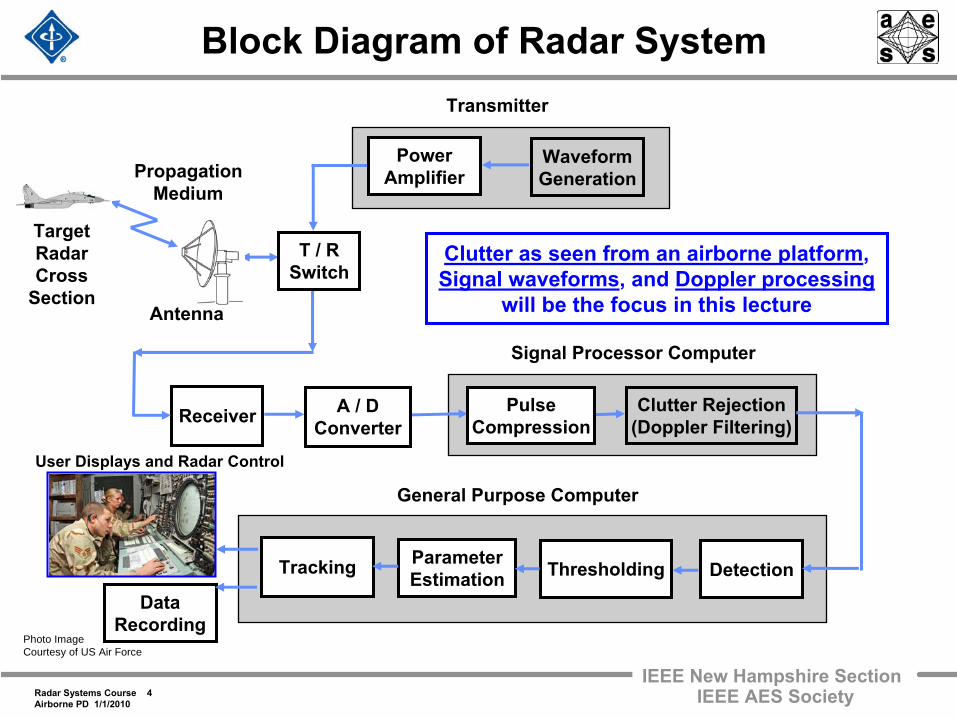
Block Diagram of Radar System
Antenna
PropagationMedium
TargetRadarCross
Section
Transmitter
General Purpose Computer
Tracking
DataRecording
ParameterEstimation
WaveformGeneration
Detection
PowerAmplifier
T / RSwitch
Signal Processor Computer
Thresholding
User Displays and Radar Control
Photo ImageCourtesy of US Air Force
Clutter as seen from an airborne platform, Signal waveforms, and Doppler processing
will be the focus in this lecture
Radar Systems Course 5Airborne PD 1/1/2010
IEEE New Hampshire SectionIEEE AES Society
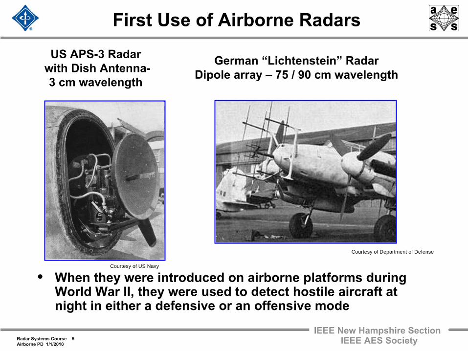
First Use of Airborne Radars
• When they were introduced on airborne platforms during World War II, they were used to detect hostile aircraft at night in either a defensive or an offensive mode
US APS-3 Radarwith Dish Antenna-3 cm wavelength
German “Lichtenstein”
RadarDipole array –
75 / 90 cm wavelength
Courtesy of US Navy
Courtesy of Department of Defense
Radar Systems Course 6Airborne PD 1/1/2010
IEEE New Hampshire SectionIEEE AES Society
Role of Airborne Military Radars
• Missions and Functions– Surveillance, Tracking, Fire Control– Reconnaissance– Intelligence
• Examples– Air-to-air fighter combat
Aircraft interception (against air breathing targets)– Airborne Early warning– Air to ground missions – Close air support – Ground target detection and tracking
• Radar modes– Pulse Doppler radar– Synthetic Aperture radar– Displaced Phase Center Antenna (DPCA)– Ground Moving Target Indication
Radar Systems Course 7Airborne PD 1/1/2010
IEEE New Hampshire SectionIEEE AES Society
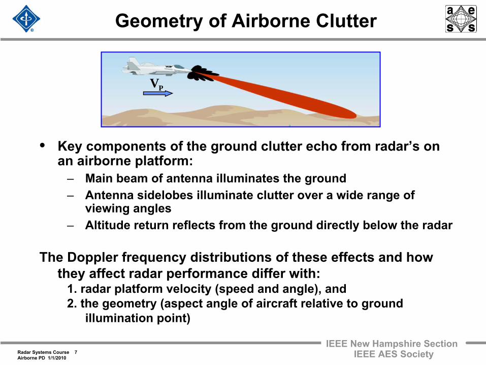
Geometry of Airborne Clutter
• Key components of the ground clutter echo from radar’s on an airborne platform:
– Main beam of antenna illuminates the ground– Antenna sidelobes illuminate clutter over a wide range of
viewing angles– Altitude return reflects from the ground directly below the radar
The Doppler frequency distributions of these effects and how they affect radar performance differ with:
1. radar platform velocity (speed and angle), and 2. the geometry (aspect angle of aircraft relative to ground
illumination point)
PV
Radar Systems Course 8Airborne PD 1/1/2010
IEEE New Hampshire SectionIEEE AES Society
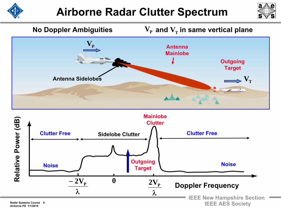
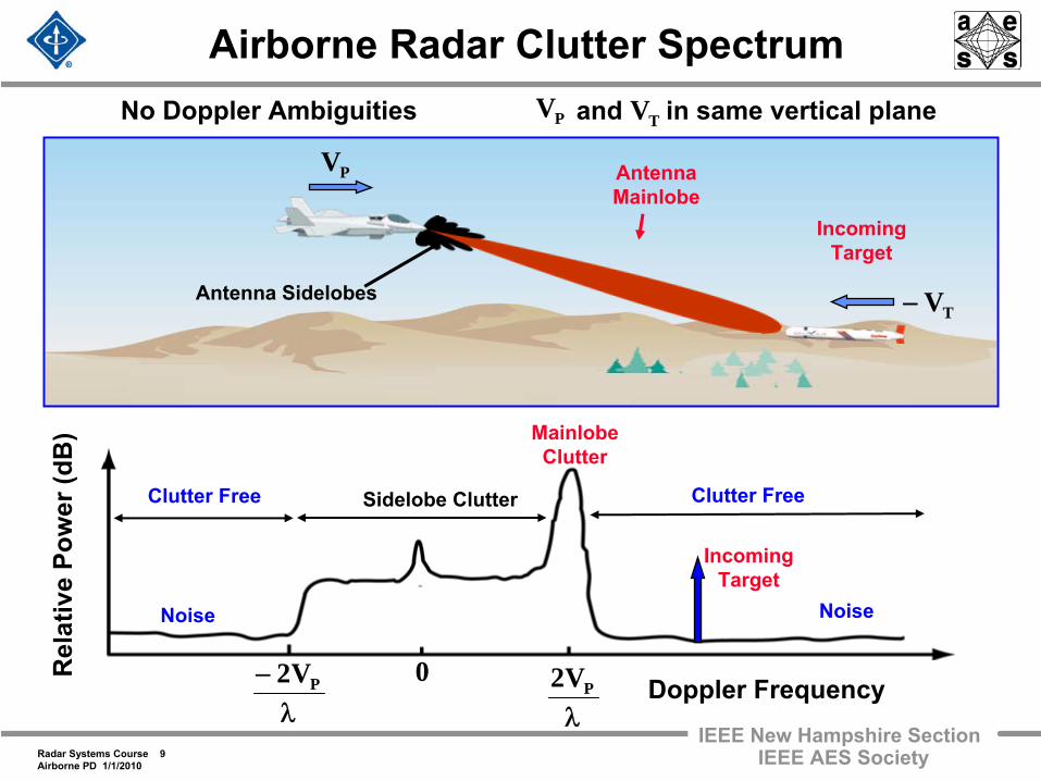
Airborne Radar Clutter Spectrum
Antenna Mainlobe
Antenna Sidelobes
PV
Outgoing Target
Rel
ativ
e Po
wer
(dB
)
λPV20
λ− PV2
Outgoing Target
Doppler Frequency
Noise Noise
Clutter Free Clutter FreeSidelobe Clutter
Mainlobe Clutter
TV
No Doppler Ambiguities and in same vertical plane PV TV
Radar Systems Course 9Airborne PD 1/1/2010
IEEE New Hampshire SectionIEEE AES Society
Airborne Radar Clutter Spectrum
Antenna Mainlobe
Antenna Sidelobes
PV
Incoming Target
Rel
ativ
e Po
wer
(dB
)
λPV20
λ− PV2 Doppler Frequency
Noise Noise
Clutter Free Clutter FreeSidelobe Clutter
Mainlobe Clutter
Incoming Target
No Doppler Ambiguities and in same vertical plane PV TV
TV−
Radar Systems Course 10Airborne PD 1/1/2010
IEEE New Hampshire SectionIEEE AES Society
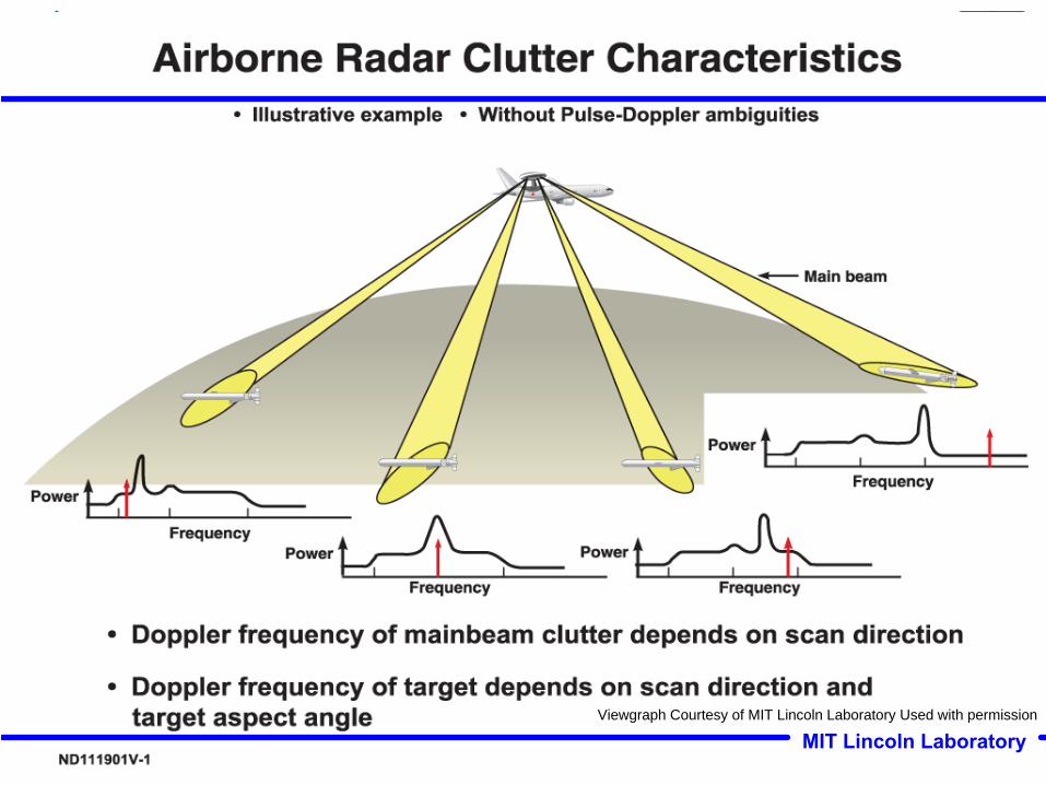
MIT Lincoln LaboratoryViewgraph Courtesy of MIT Lincoln Laboratory Used with permission
Radar Systems Course 11Airborne PD 1/1/2010
IEEE New Hampshire SectionIEEE AES Society
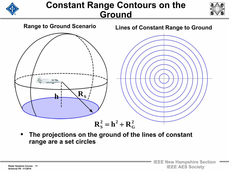
Constant Range Contours on the Ground
• The projections on the ground of the lines of constant range are a set circles
Range to Ground Scenario Lines of Constant Range to Ground
2G
22S RhR +=
SRh
Radar Systems Course 12Airborne PD 1/1/2010
IEEE New Hampshire SectionIEEE AES Society
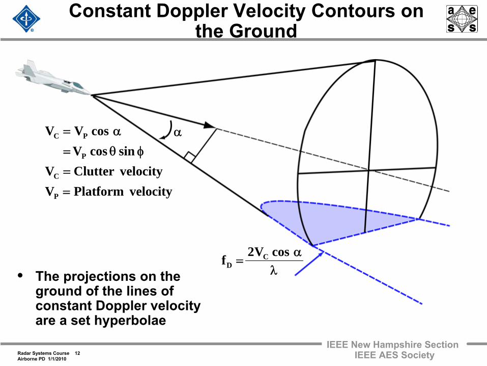
Constant Doppler Velocity Contours on the Ground
• The projections on the ground of the lines of constant Doppler velocity are a set hyperbolae
α
velocityPlatformVvelocityClutterVsincosV
cosVV
P
C
P
PC
=
=
φθ=
α=
λα
=cosV2f C
D
Radar Systems Course 13Airborne PD 1/1/2010
IEEE New Hampshire SectionIEEE AES Society
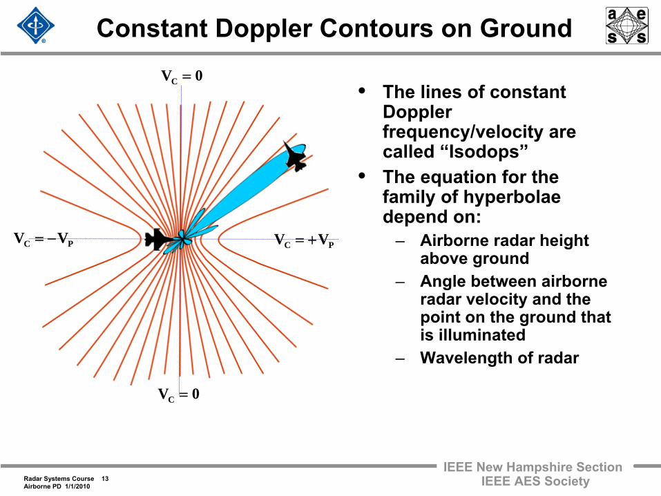
Constant Doppler Contours on Ground
• The lines of constant Doppler frequency/velocity are called “Isodops”
• The equation for the family of hyperbolae depend on:
– Airborne radar height above ground
– Angle between airborne radar velocity and the point on the ground that is illuminated
– Wavelength of radar
PC VV −= PC VV +=
0VC =
0VC =
Radar Systems Course 14Airborne PD 1/1/2010
IEEE New Hampshire SectionIEEE AES Society
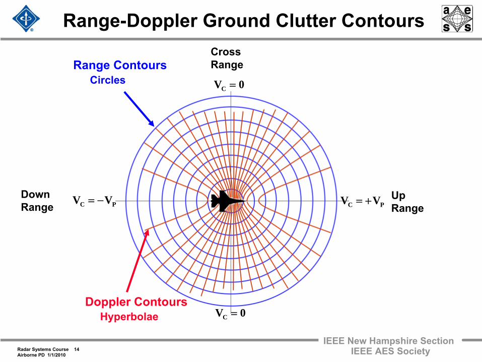
Range-Doppler Ground Clutter Contours
Up Range
Cross Range
Down Range
Range ContoursCircles
Doppler ContoursHyperbolae
PC VV +=PC VV −=
0VC =
0VC =
Radar Systems Course 15Airborne PD 1/1/2010
IEEE New Hampshire SectionIEEE AES Society
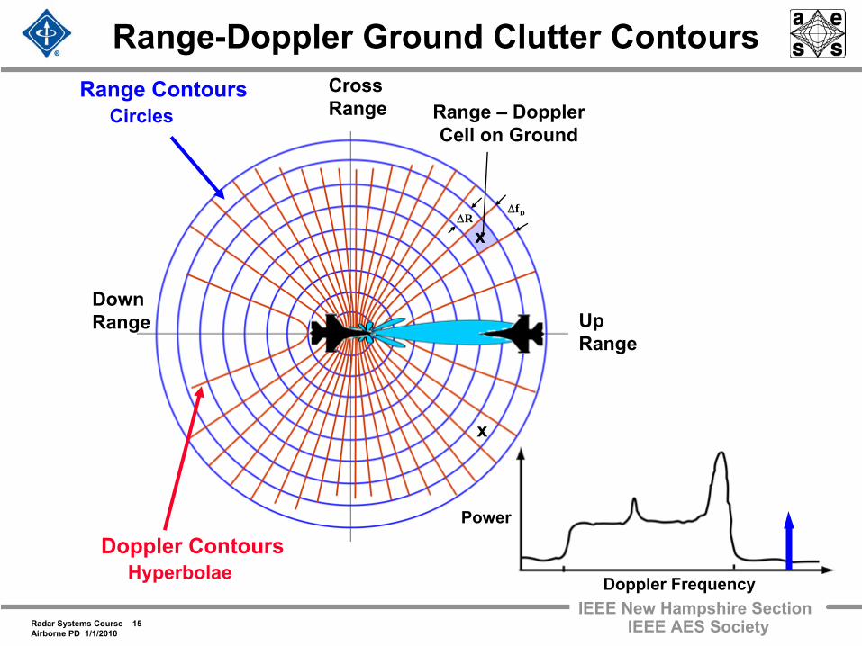
Range-Doppler Ground Clutter Contours
Up Range
Cross Range
Down Range
Range ContoursCircles
Doppler ContoursHyperbolae
RΔ DfΔ
Range –
Doppler Cell on Ground
x
x
Power
Doppler Frequency
Radar Systems Course 16Airborne PD 1/1/2010
IEEE New Hampshire SectionIEEE AES Society
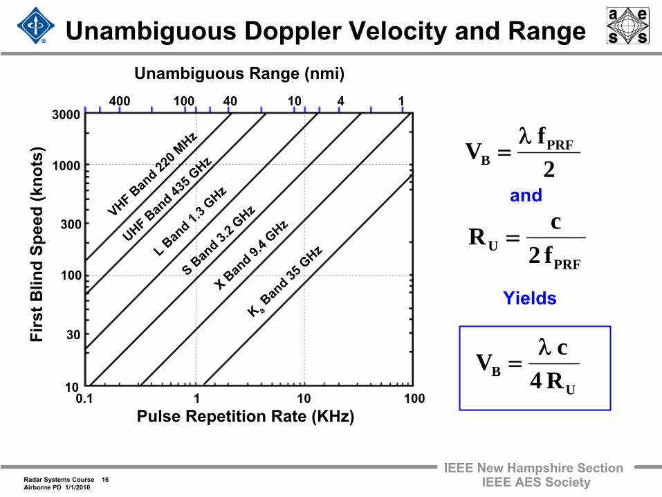
Unambiguous Doppler Velocity and Range
2fV PRF
Bλ
=
PRFU f2
cR =
and
Firs
t Blin
d Sp
eed
(kno
ts)
10
30
100
1000
3000
300
Pulse Repetition Rate (KHz)0.1 1 10 100
Unambiguous Range (nmi)400 100 40 10 4 1
K aBan
d 35 G
HzL Band 1.
3 GHz
UHF Band 43
5 GHz
X Band 9.
4 GHz
S Band 3.
2 GHzVHF Ban
d 220 M
Hz
Yields
UB R4
cV λ=
Radar Systems Course 17Airborne PD 1/1/2010
IEEE New Hampshire SectionIEEE AES Society
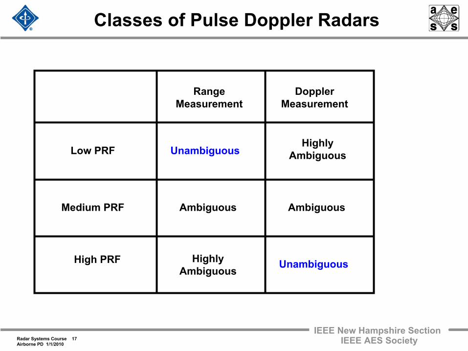
Classes of Pulse Doppler Radars
HighlyAmbiguous
Ambiguous
HighlyAmbiguous
Ambiguous
Unambiguous
Unambiguous
RangeMeasurement
DopplerMeasurement
Low PRF
Medium PRF
High PRF
Radar Systems Course 18Airborne PD 1/1/2010
IEEE New Hampshire SectionIEEE AES Society
Missions for Airborne Military Radars “The Big Picture”
• Fighter / Interceptor Radars– Antenna size constraints imply frequencies at X-Band or higher
Reasonable angle beamwidths – This implies Medium or
High
PRF pulse Doppler modes for look down capability
• Wide Area Surveillance and Tracking– Pulse Doppler solutions
Low, Medium and/or High
PRFs may be used depending on the specific mission
– E-2C UHF – AWACS S-Band – Joint Stars X-Band
• Synthetic Aperture Radars will be discussed in a later lecture
Radar Systems Course 19Airborne PD 1/1/2010
IEEE New Hampshire SectionIEEE AES Society
Outline
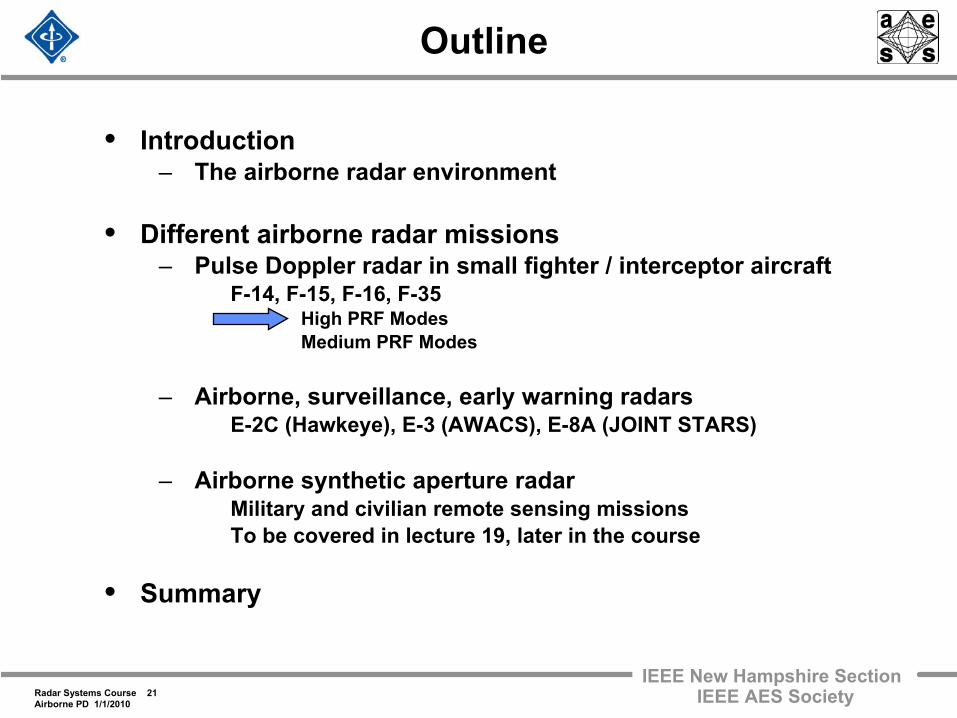
• Introduction– The airborne radar environment
• Different airborne radar missions– Pulse Doppler radar in small fighter / interceptor aircraft
F-14, F-15, F-16, F-35 High PRF Modes Medium PRF Modes
– Airborne, surveillance, early warning radars E-2C (Hawkeye), E-3 (AWACS), E-8A (JOINT STARS)
– Airborne synthetic aperture radar Military and civilian remote sensing missions To be covered in lecture 19, later in the course
• Summary
Radar Systems Course 20Airborne PD 1/1/2010
IEEE New Hampshire SectionIEEE AES Society
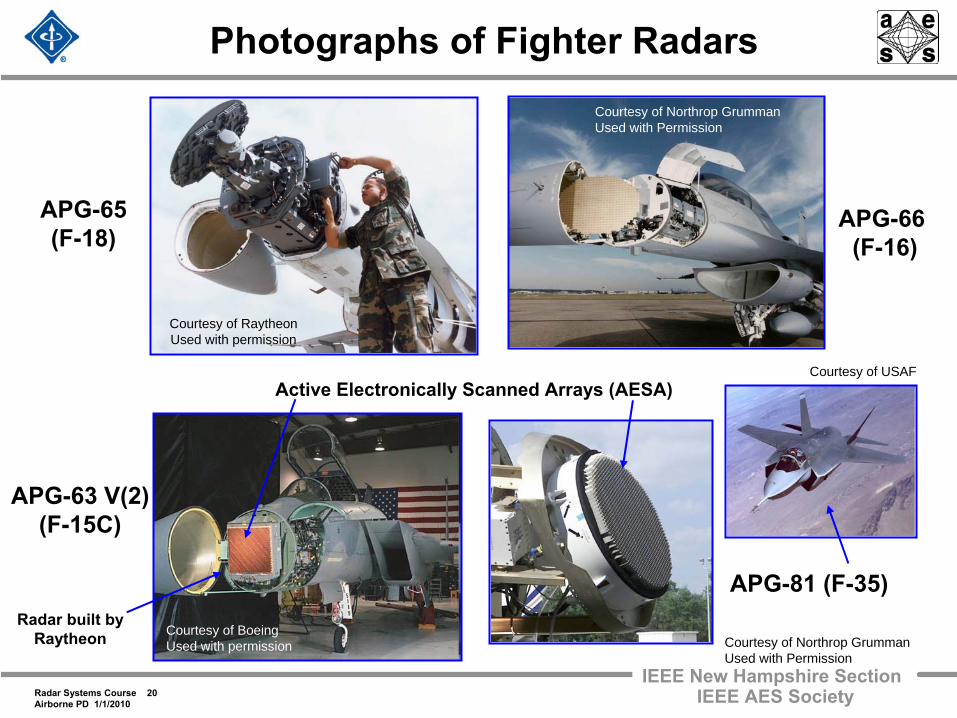
Photographs of Fighter Radars
APG-66 (F-16)
Courtesy of Northrop GrummanUsed with Permission
APG-81 (F-35)
Courtesy of Northrop GrummanUsed with Permission
APG-65(F-18)
Courtesy of RaytheonUsed with permission
Courtesy of BoeingUsed with permission
APG-63 V(2)(F-15C)
Active Electronically Scanned Arrays (AESA)
Radar built by Raytheon
Courtesy of USAF
Radar Systems Course 21Airborne PD 1/1/2010
IEEE New Hampshire SectionIEEE AES Society
Outline
• Introduction– The airborne radar environment
• Different airborne radar missions– Pulse Doppler radar in small fighter / interceptor aircraft
F-14, F-15, F-16, F-35 High PRF Modes Medium PRF Modes
– Airborne, surveillance, early warning radars E-2C (Hawkeye), E-3 (AWACS), E-8A (JOINT STARS)
– Airborne synthetic aperture radar Military and civilian remote sensing missions To be covered in lecture 19, later in the course
• Summary
Radar Systems Course 22Airborne PD 1/1/2010
IEEE New Hampshire SectionIEEE AES Society
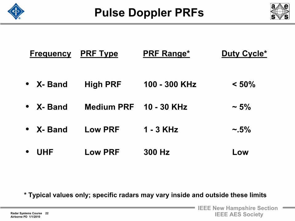
Pulse Doppler PRFs
• X-
Band
High PRF
100 -
300 KHz
< 50%
• X-
Band
Medium PRF
10 -
30 KHz
~ 5%
• X-
Band
Low PRF
1 -
3 KHz
~.5%
• UHF
Low PRF
300 Hz
Low
Frequency
PRF Type
PRF Range*
Duty Cycle*
* Typical values only; specific radars may vary inside and outside these limits
Radar Systems Course 23Airborne PD 1/1/2010
IEEE New Hampshire SectionIEEE AES Society
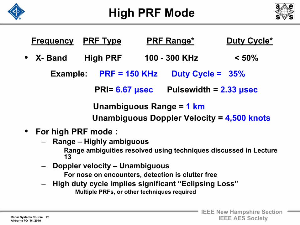
High PRF Mode
• X-
Band
High PRF
100 -
300 KHz
< 50%
• For high PRF mode :– Range –
Highly ambiguous Range ambiguities resolved using techniques discussed in Lecture
13
– Doppler velocity –
Unambiguous For nose on encounters, detection is clutter free
– High duty cycle implies significant “Eclipsing Loss” Multiple PRFs, or other techniques required
Frequency
PRF Type
PRF Range*
Duty Cycle*
Example: PRF = 150 KHz Duty Cycle = 35%
PRI= 6.67 μsec
Pulsewidth = 2.33 μsec
Unambiguous Range = 1 kmUnambiguous Doppler Velocity =
4,500 knots
Radar Systems Course 24Airborne PD 1/1/2010
IEEE New Hampshire SectionIEEE AES Society
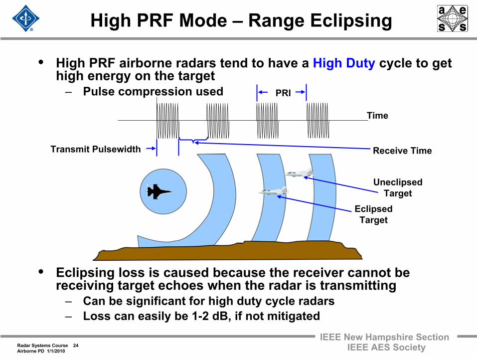
• High PRF airborne radars tend to have a High Duty
cycle to get high energy on the target
– Pulse compression used
• Eclipsing loss is caused because the receiver cannot be receiving target echoes when the radar is transmitting
– Can be significant for high duty cycle radars– Loss can easily be 1-2 dB, if not mitigated
High PRF Mode –
Range Eclipsing
Time
Transmit Pulsewidth
PRI
UneclipsedTarget
Receive Time
EclipsedTarget
Radar Systems Course 25Airborne PD 1/1/2010
IEEE New Hampshire SectionIEEE AES Society
High PRF Pulse Doppler Radar
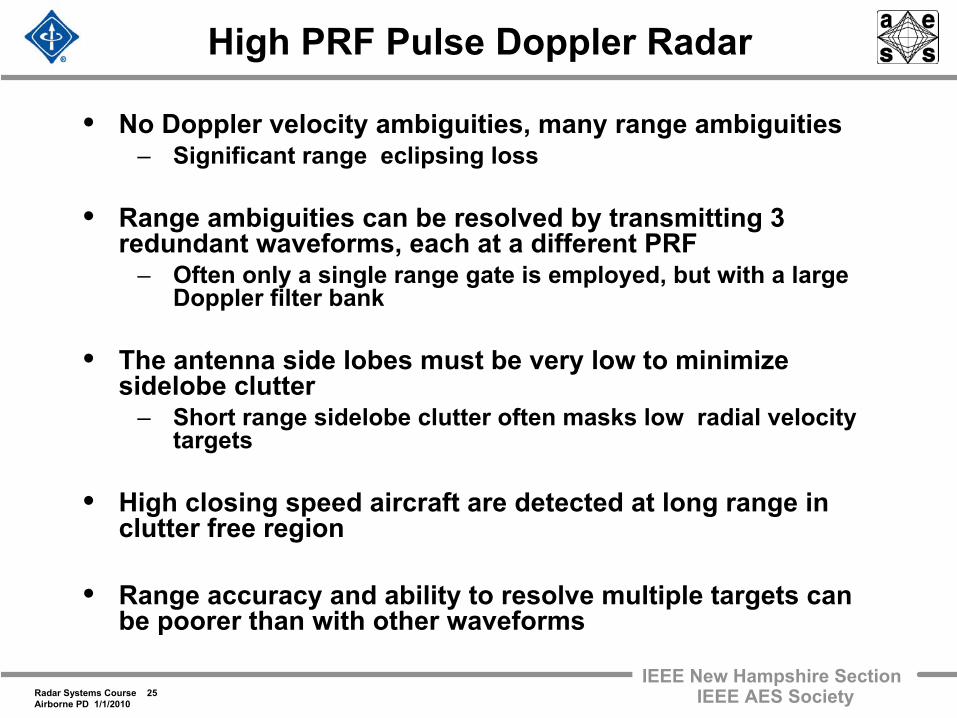
• No Doppler velocity ambiguities, many range ambiguities– Significant range eclipsing loss
• Range ambiguities can be resolved by transmitting 3 redundant waveforms, each at a different PRF
– Often only a single range gate is employed, but with a large Doppler filter bank
• The antenna side lobes must be very low to minimize sidelobe clutter
– Short range sidelobe clutter often masks low radial velocity targets
• High closing speed aircraft are detected at long range in clutter free region
• Range accuracy and ability to resolve multiple targets can be poorer than with other waveforms
Radar Systems Course 26Airborne PD 1/1/2010
IEEE New Hampshire SectionIEEE AES Society
Outline
• Introduction– The airborne radar environment
• Different airborne radar missions– Pulse Doppler radar in small fighter / interceptor aircraft
F-14, F-15, F-16, F-35 High PRF Modes Medium PRF Modes
– Airborne, surveillance, early warning radars E-2C (Hawkeye), E-3 (AWACS), E-8A (JOINT STARS)
– Airborne synthetic aperture radar Military and civilian remote sensing missions To be covered in lecture 19, later in the course
• Summary
Radar Systems Course 27Airborne PD 1/1/2010
IEEE New Hampshire SectionIEEE AES Society
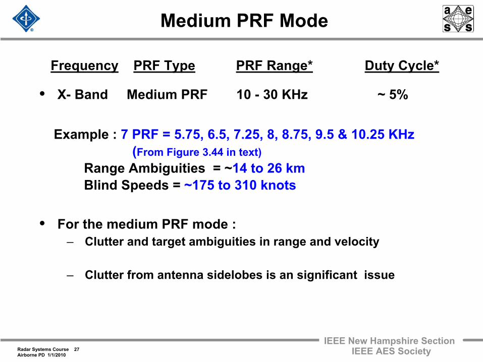
• X-
Band Medium PRF
10 -
30 KHz
~ 5%
• For the medium PRF mode :– Clutter and target ambiguities in range and velocity
– Clutter from antenna sidelobes is an significant issue
Medium PRF Mode
Frequency
PRF Type
PRF Range*
Duty Cycle*
Example : 7
PRF = 5.75, 6.5, 7.25, 8, 8.75, 9.5 & 10.25 KHz (From Figure 3.44 in text)
Range Ambiguities = ~14 to 26 kmBlind Speeds =
~175 to 310 knots
Radar Systems Course 28Airborne PD 1/1/2010
IEEE New Hampshire SectionIEEE AES Society
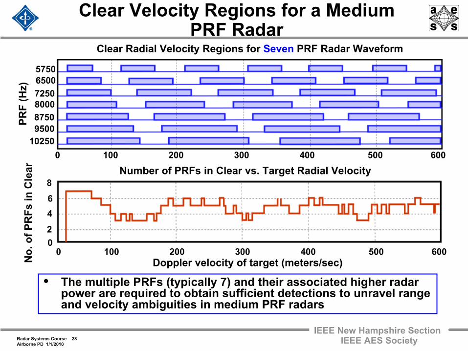
Clear Velocity Regions for a Medium PRF Radar
• The multiple PRFs (typically 7) and their associated higher radar power are required to obtain sufficient detections to unravel range and velocity ambiguities in medium PRF radars
Clear Radial Velocity Regions for Seven
PRF Radar Waveform
0 100 200 300 400 500 600Doppler velocity of target (meters/sec)
0 100 200 300 400 500 600
Number of PRFs in Clear vs. Target Radial Velocity
PRF
(Hz)
575065007250800087509500
10250
No.
of P
RFs
in C
lear
02
468
Radar Systems Course 29Airborne PD 1/1/2010
IEEE New Hampshire SectionIEEE AES Society
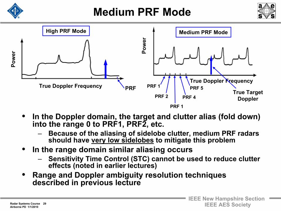
Medium PRF Mode
• In the Doppler domain, the target and clutter alias (fold down) into the range 0 to PRF1, PRF2, etc.
– Because of the aliasing of sidelobe clutter, medium PRF radars should have very low sidelobes
to mitigate this problem• In the range domain similar aliasing occurs
– Sensitivity Time Control (STC) cannot be used to reduce clutter effects (noted in earlier lectures)
• Range and Doppler ambiguity resolution techniques described in previous lecture
High PRF Mode
True Doppler Frequency
Pow
er
PRFPRF 2
PRF 1
PRF 1
PRF 4
PRF 5True Doppler Frequency
Medium PRF Mode
Pow
er
True Target Doppler
Radar Systems Course 30Airborne PD 1/1/2010
IEEE New Hampshire SectionIEEE AES Society
Medium PRF Pulse Doppler Radar
• Both range and Doppler ambiguities exist– Seven or eight different PRFs must be used – Insures target seen at enough Doppler frequencies to resolve range
ambiguities– Transmitter larger because of redundant waveforms used to resolve
ambiguities
• There is no clutter free region– Fewer range ambiguities implies less of a problem with sidelobe
clutter– Antenna must have low sidelobes to reduce sidelobe clutter
• Often best single waveform for airborne fighter / interceptor
• More range gates than high PRF, but fewer Doppler filters for each range gate
• Better range accuracy and Doppler resolution than high PRF systems
Radar Systems Course 31Airborne PD 1/1/2010
IEEE New Hampshire SectionIEEE AES Society
Outline
• Introduction– The airborne radar environment
• Different airborne radar missions– Pulse Doppler radar in small fighter / interceptor aircraft
F-14, F-15, F-16, F-35
– Airborne, surveillance, early warning radars E-2C (Hawkeye), E-3 (AWACS), E-8A (JOINT STARS)
– Airborne synthetic aperture radar Military and civilian remote sensing missions To be covered in lecture 19, later in the course
• Summary
Radar Systems Course 32Airborne PD 1/1/2010
IEEE New Hampshire SectionIEEE AES Society
Airborne Surveillance & Tracking Radars
• Missions and Functions– Surveillance, Tracking, Fire Control– Reconnaissance– Intelligence
• Examples– Airborne early warning – Ground target detection and tracking
• Radar modes– Pulse Doppler radar– Synthetic Aperture radar– Displaced Phase Center Antenna (DPCA)– Other modes/techniques
Elevated radar platforms provide long range andover the horizon coverage of airborne and ground based targets
Radar Systems Course 33Airborne PD 1/1/2010
IEEE New Hampshire SectionIEEE AES Society
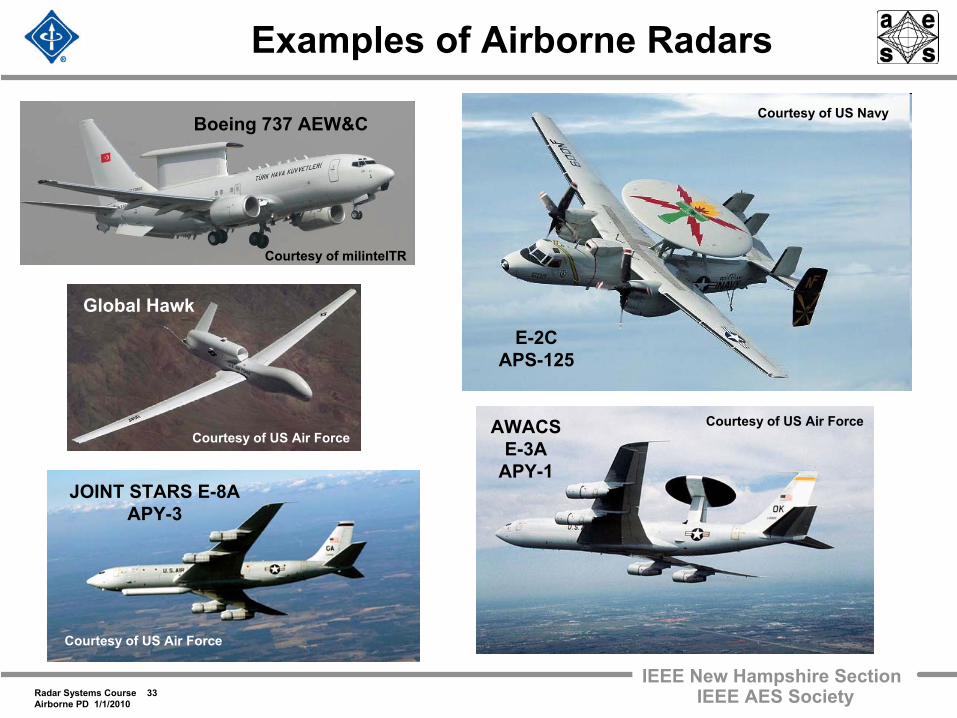
Examples of Airborne Radars
Courtesy of US Air ForceAWACSE-3A
APY-1
E-2CAPS-125
Courtesy of US Navy
JOINT STARS E-8AAPY-3
Courtesy of US Air Force
Courtesy of milintelTR
Boeing 737 AEW&C
Courtesy of US Air Force
Global Hawk
Radar Systems Course 34Airborne PD 1/1/2010
IEEE New Hampshire SectionIEEE AES Society
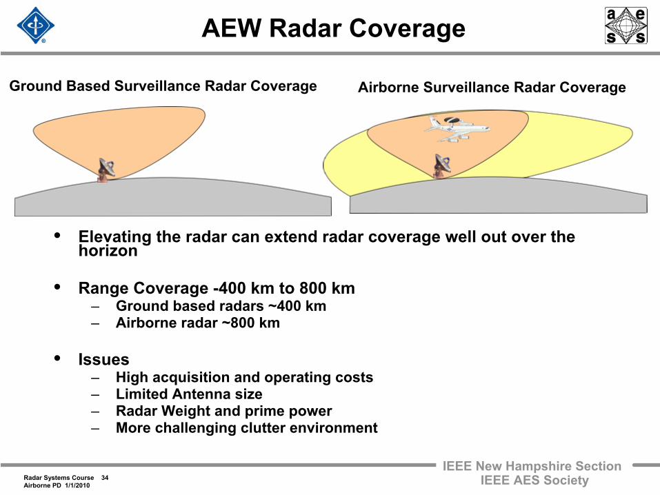
AEW Radar Coverage
• Elevating the radar can extend radar coverage well out over the horizon
• Range Coverage -400 km to 800 km– Ground based radars ~400 km– Airborne radar ~800 km
• Issues– High acquisition and operating costs– Limited Antenna size– Radar Weight and prime power – More challenging clutter environment
Ground Based Surveillance Radar Coverage Airborne Surveillance Radar Coverage
Radar Systems Course 35Airborne PD 1/1/2010
IEEE New Hampshire SectionIEEE AES Society
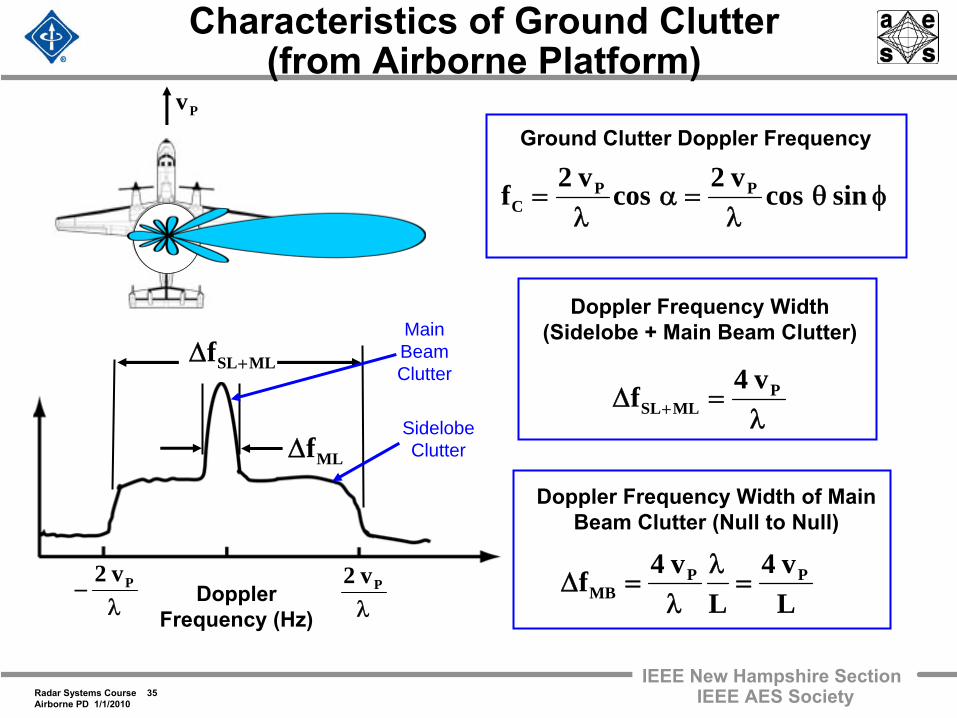
Characteristics of Ground Clutter (from Airborne Platform)
λ− Pv2
λPv2
Doppler Frequency (Hz)
MLfΔ
MLSLf +Δ
Ground Clutter Doppler Frequency
φθλ
=αλ
= sincosv2cosv2f PPC
Doppler Frequency Width (Sidelobe + Main Beam Clutter)
λ=Δ +
PMLSL
v4f
Doppler Frequency Width of Main Beam Clutter (Null to Null)
Lv4
Lv4f PP
MB =λ
λ=Δ
Pv
MainBeamClutter
SidelobeClutter
Radar Systems Course 36Airborne PD 1/1/2010
IEEE New Hampshire SectionIEEE AES Society
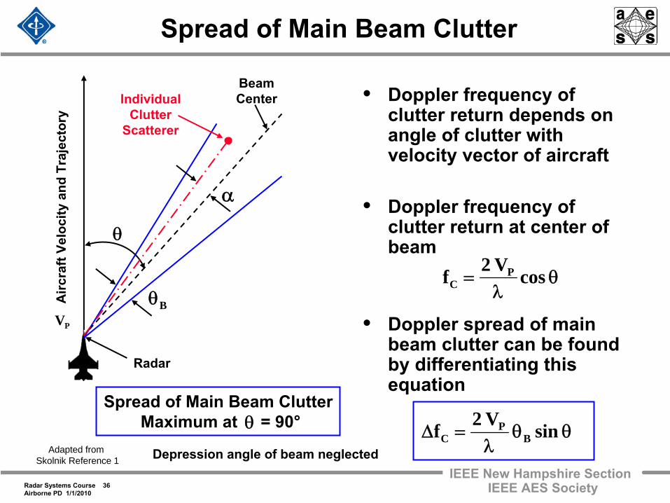
Spread of Main Beam Clutter
• Doppler frequency of clutter return depends on angle of clutter with velocity vector of aircraft
• Doppler frequency of clutter return at center of beam
• Doppler spread of main beam clutter can be found by differentiating this equation
θλ
= cosV2f PC
θ
Bθ
α
BeamCenterIndividual
ClutterScatterer
Radar
PV
Airc
raft
Velo
city
and
Tra
ject
ory
θθλ
=Δ sinV2f BP
C
Spread of Main Beam ClutterMaximum at = 90°θ
Adapted from Skolnik Reference 1 Depression angle of beam neglected
Radar Systems Course 37Airborne PD 1/1/2010
IEEE New Hampshire SectionIEEE AES Society
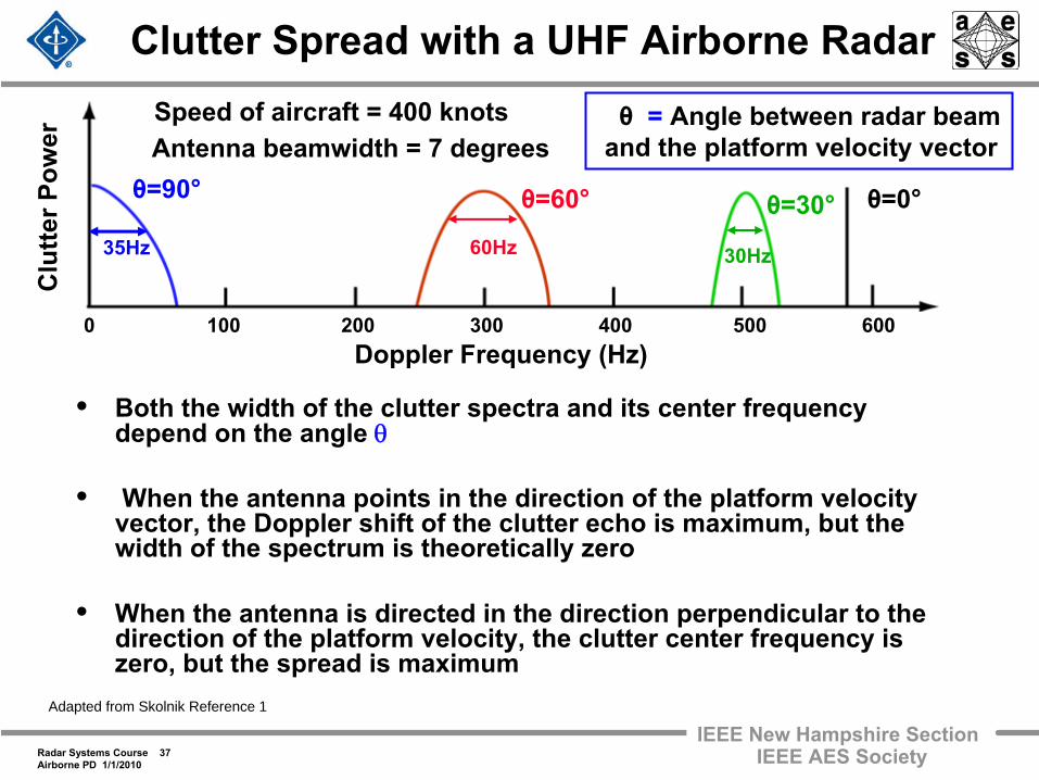
35Hz
Clutter Spread with a UHF Airborne Radar
• Both the width of the clutter spectra and its center frequency depend on the angle θ
• When the antenna points in the direction of the platform velocity vector, the Doppler shift of the clutter echo is maximum, but the width of the spectrum is theoretically zero
• When the antenna is directed in the direction perpendicular to the direction of the platform velocity, the clutter center frequency
is zero, but the spread is maximum
θ=90° θ=0°θ=30°θ=60°
Doppler Frequency (Hz)0 100 200 300 400 500 600
Clu
tter P
ower
Speed of aircraft = 400 knots θ
= Angle between radar beamand the platform velocity vectorAntenna beamwidth = 7 degrees
30Hz60Hz
Adapted from Skolnik Reference 1
Radar Systems Course 38Airborne PD 1/1/2010
IEEE New Hampshire SectionIEEE AES Society
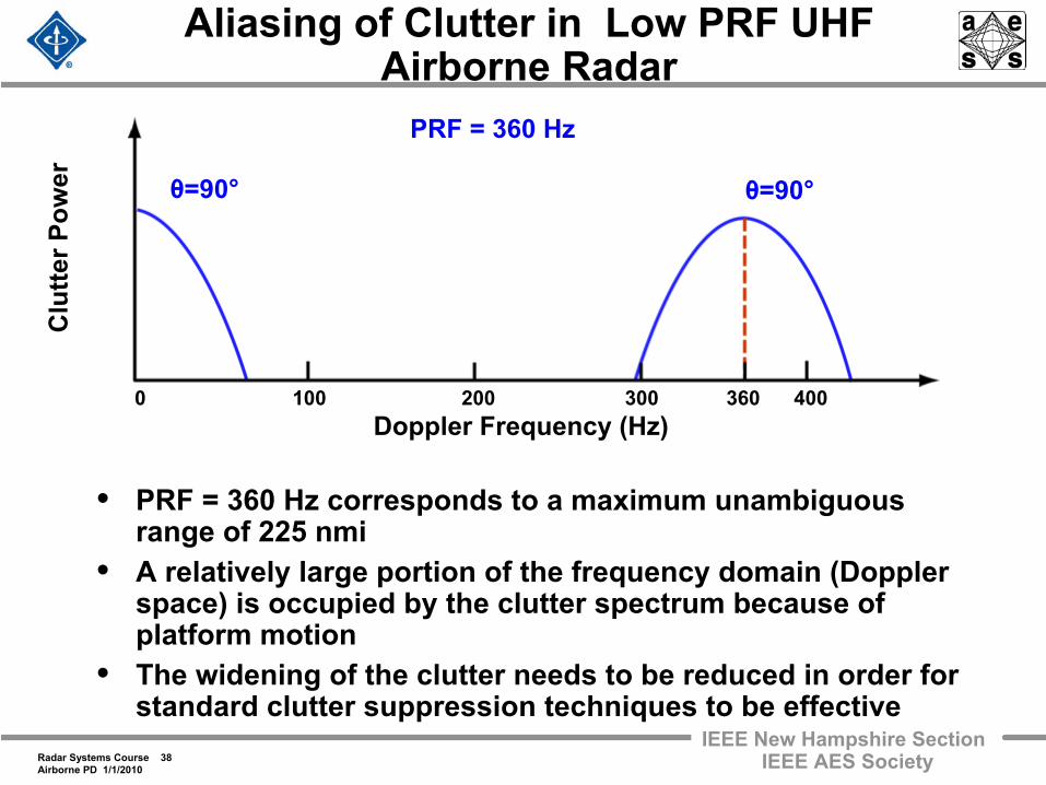
Aliasing of Clutter in Low PRF UHF Airborne Radar
• PRF = 360 Hz corresponds to a maximum unambiguous range of 225 nmi
• A relatively large portion of the frequency domain (Doppler space) is occupied by the clutter spectrum because of platform motion
• The widening of the clutter needs to be reduced in order for standard clutter suppression techniques to be effective
θ=90° θ=90°
PRF = 360 Hz
Clu
tter P
ower
Doppler Frequency (Hz)0 100 200 300 360 400
Radar Systems Course 39Airborne PD 1/1/2010
IEEE New Hampshire SectionIEEE AES Society
AEW Airborne Radar Clutter Rejection
• There are 2 effects that can seriously degrade the performance of a radar on a moving platform
– A non-zero Doppler clutter shift– A widening of the clutter spectrum
• These may be compensated for by two different techniques– TACCAR (Time Averaged Clutter Coherent Airborne Radar)
The change in center frequency of the clutter spectrum– DPCA (Displaced Phase Center Antenna)
The widening of the clutter spectrum
• Radars which have used these techniques, over the years, to compensate for platform motion are Airborne Early Warning radars
Radar Systems Course 40Airborne PD 1/1/2010
IEEE New Hampshire SectionIEEE AES Society
Compensation for Clutter Doppler Shift
• TACCAR (Time Averaged Clutter Coherent Airborne Radar)– Also called “Clutter Lock MTI”
• The Doppler frequency shift from ground clutter can be compensated by using the clutter echo signal itself to set the frequency of the reference oscillator (or coho)
– This process centers the ground clutter to zero Doppler frequency
– The standard MTI filter (notch at zero Doppler) attenuates the ground clutter
• This technique has been used in ground based radars to mitigate the effect of moving clutter
– Not used after the advent of Doppler filter processing
Radar Systems Course 41Airborne PD 1/1/2010
IEEE New Hampshire SectionIEEE AES Society
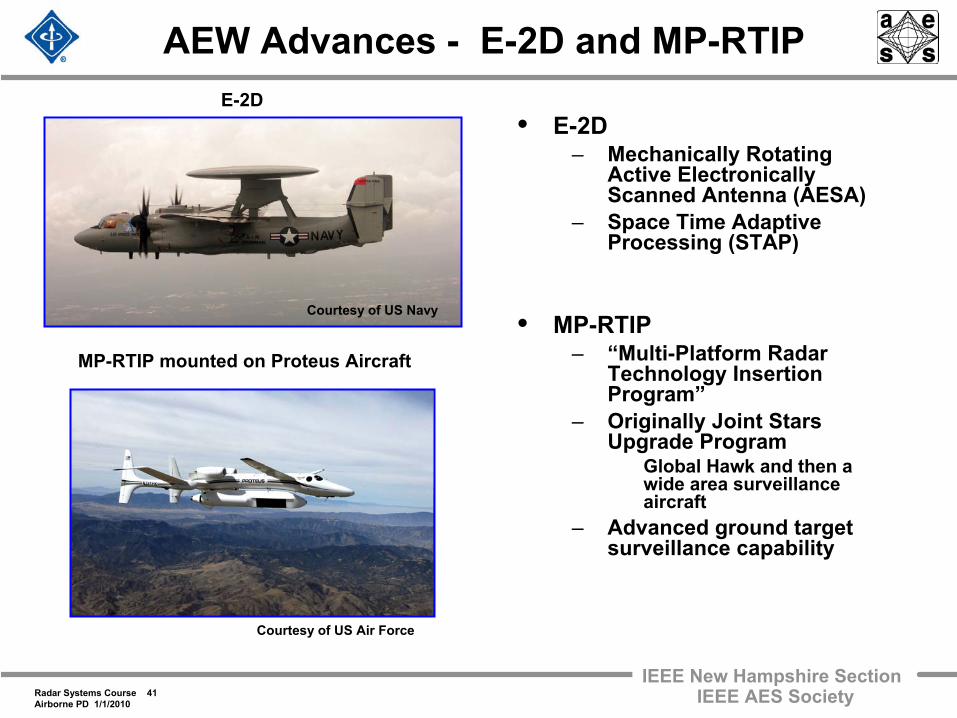
AEW Advances -
E-2D and MP-RTIP
• E-2D– Mechanically Rotating
Active Electronically Scanned Antenna (AESA)
– Space Time Adaptive Processing (STAP)
• MP-RTIP– “Multi-Platform Radar
Technology Insertion Program”
– Originally Joint Stars Upgrade Program
Global Hawk and then a wide area surveillance aircraft
– Advanced ground target surveillance capability
E-2D
MP-RTIP mounted on Proteus Aircraft
Courtesy of US Air Force
Courtesy of US Navy
Radar Systems Course 42Airborne PD 1/1/2010
IEEE New Hampshire SectionIEEE AES Society
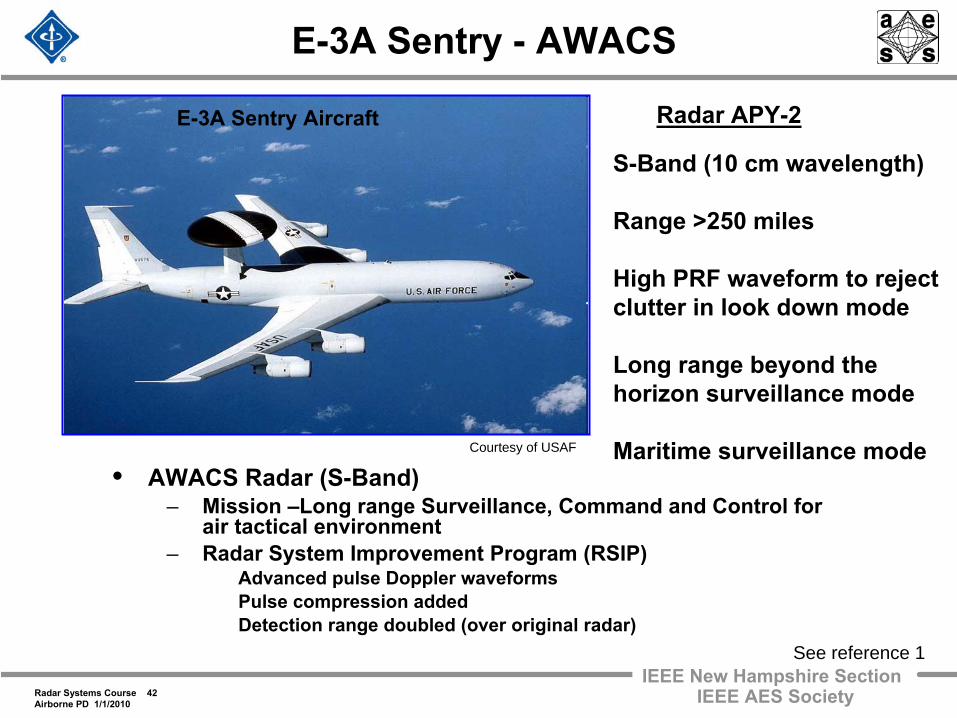
E-3A Sentry -
AWACS
E-3A Sentry Aircraft
• AWACS Radar (S-Band) – Mission –Long range Surveillance, Command and Control for
air tactical environment– Radar System Improvement Program (RSIP)
Advanced pulse Doppler waveforms Pulse compression added Detection range doubled (over original radar)
Courtesy of USAF
See reference 1
Radar APY-2
S-Band (10 cm wavelength)
Range >250 miles
High PRF waveform to reject clutter in look down mode
Long range beyond the horizon surveillance mode
Maritime surveillance mode
Radar Systems Course 43Airborne PD 1/1/2010
IEEE New Hampshire SectionIEEE AES Society
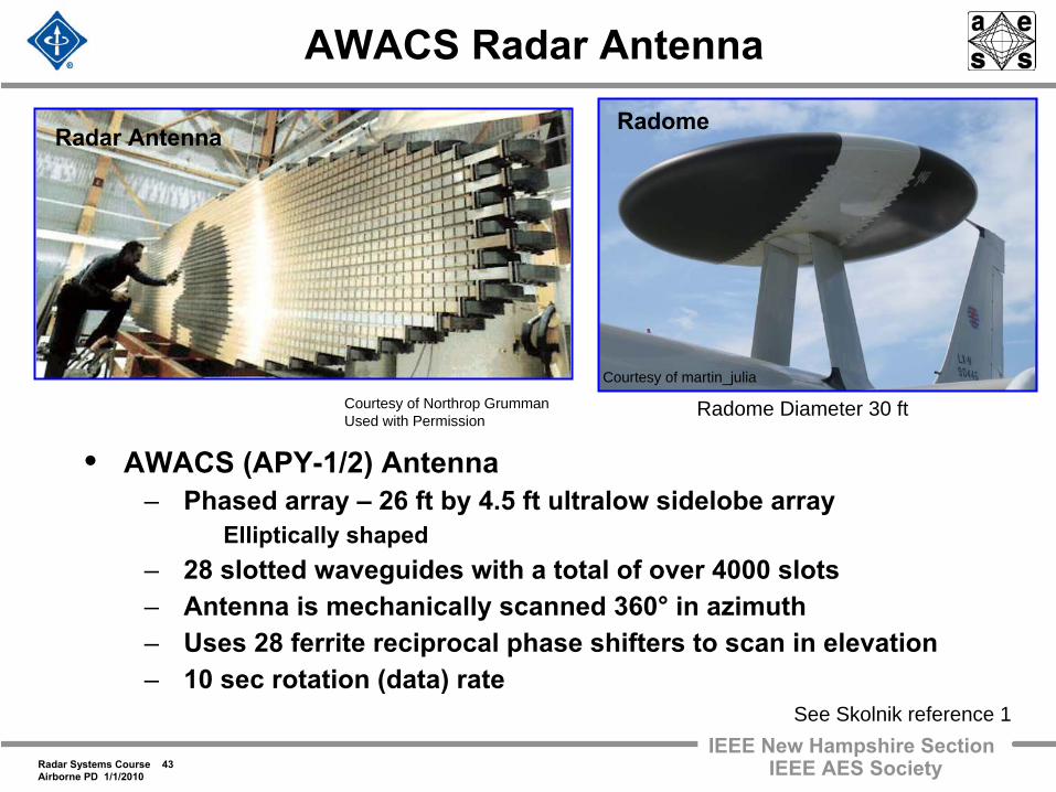
AWACS Radar Antenna
• AWACS (APY-1/2) Antenna– Phased array –
26 ft by 4.5 ft ultralow sidelobe array Elliptically shaped
– 28 slotted waveguides with a total of over 4000 slots– Antenna is mechanically scanned 360°
in azimuth– Uses 28 ferrite reciprocal phase shifters to scan in elevation– 10 sec rotation (data) rate
Radome
Courtesy of martin_julia
Radar Antenna
Courtesy of Northrop GrummanUsed with Permission
See Skolnik reference 1
Radome Diameter 30 ft
Radar Systems Course 44Airborne PD 1/1/2010
IEEE New Hampshire SectionIEEE AES Society
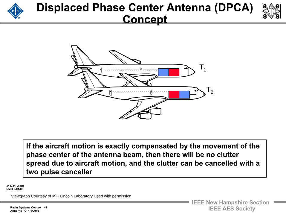
Displaced Phase Center Antenna (DPCA) Concept
344334_2.pptRMO 9-01-00
If the aircraft motion is exactly compensated by the movement of
the phase center of the antenna beam, then there will be no clutter spread due to aircraft motion, and the clutter can be cancelled with a two pulse canceller
T1
T2
Viewgraph Courtesy of MIT Lincoln Laboratory Used with permission
Radar Systems Course 45Airborne PD 1/1/2010
IEEE New Hampshire SectionIEEE AES Society
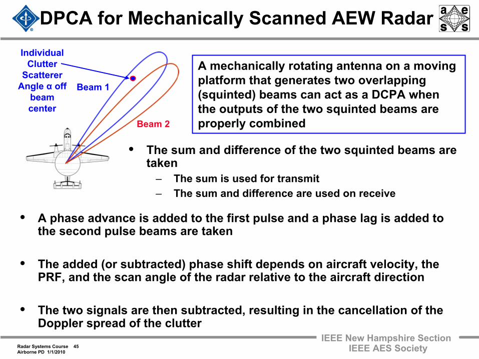
DPCA for Mechanically Scanned AEW Radar
• The sum and difference of the two squinted beams are taken
– The sum is used for transmit– The sum and difference are used on receive
Beam 1
Beam 2
A mechanically rotating antenna on a moving platform that generates two overlapping (squinted) beams can act as a DCPA when the outputs of the two squinted beams are properly combined
• A phase advance is added to the first pulse and a phase lag is added to the second pulse beams are taken
• The added (or subtracted) phase shift depends on aircraft velocity, the PRF, and the scan angle of the radar relative to the aircraft direction
• The two signals are then subtracted, resulting in the cancellation of the Doppler spread of the clutter
IndividualClutter
ScattererAngle α
offbeam center
Radar Systems Course 46Airborne PD 1/1/2010
IEEE New Hampshire SectionIEEE AES Society
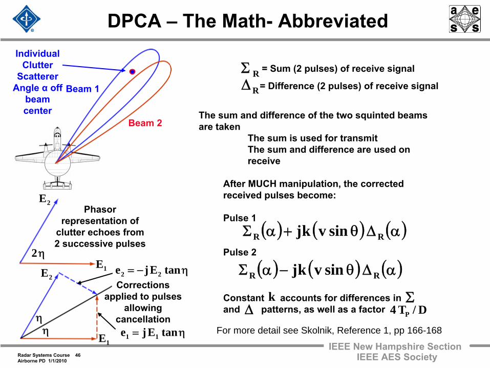
DPCA –
The Math-
Abbreviated
Beam 1
Beam 2
Corrections applied to pulses
allowing cancellation
Phasor representation of
clutter echoes from 2 successive pulses
1E
2E
2E
1E
η2
ηη
η= tanEje 11
η−= tanEje 22
RΣRΔ
= Sum (2 pulses) of receive signal
= Difference (2 pulses) of receive signal
For more detail see Skolnik, Reference 1, pp 166-168
The sum and difference of the two squinted beams are taken
The sum is used for transmitThe sum and difference are used on receive
After MUCH manipulation, the corrected received pulses become:
Pulse 1
Pulse 2
Constant accounts for differences in and patterns, as well as a factor
IndividualClutter
ScattererAngle α
offbeam center
( ) ( ) ( )αΔθ+αΣ RR sinvkj
( ) ( ) ( )αΔθ−αΣ RR sinvkj
D/T4 P
kΔ
Σ
Radar Systems Course 47Airborne PD 1/1/2010
IEEE New Hampshire SectionIEEE AES Society
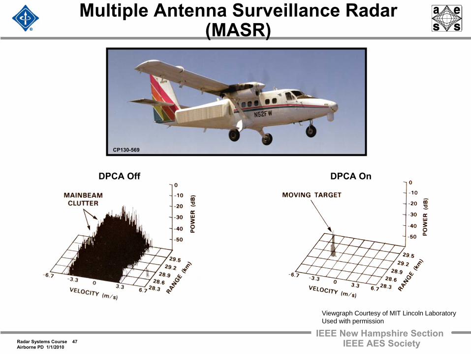
Multiple Antenna Surveillance Radar (MASR)
CP130-569
DPCA Off DPCA On
Viewgraph Courtesy of MIT Lincoln LaboratoryUsed with permission
Radar Systems Course 48Airborne PD 1/1/2010
IEEE New Hampshire SectionIEEE AES Society
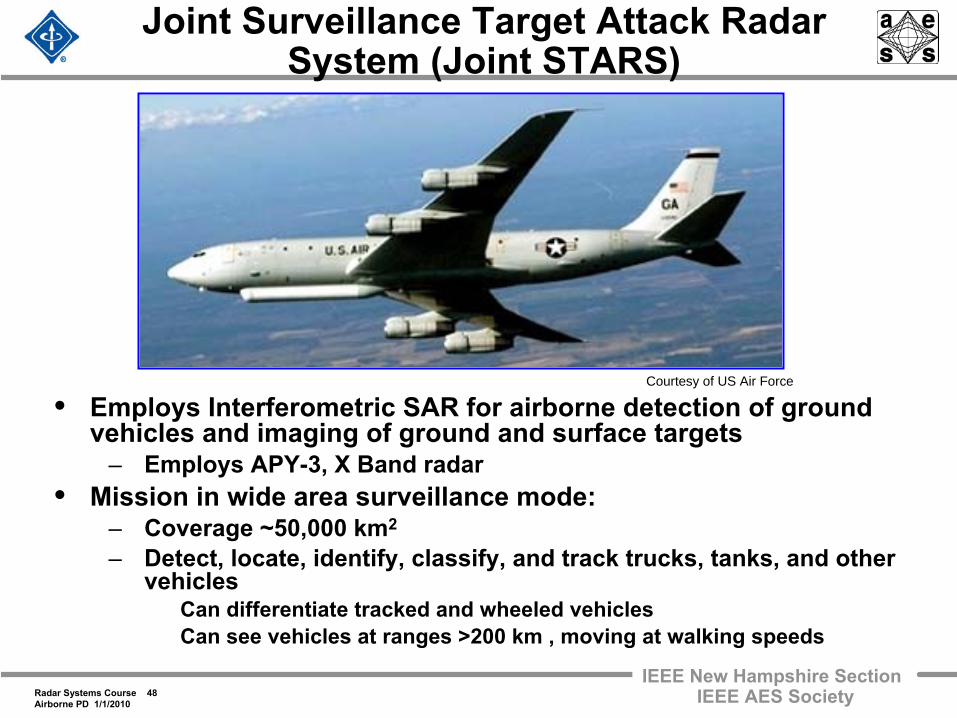
Joint Surveillance Target Attack Radar System (Joint STARS)
• Employs Interferometric SAR for airborne detection of ground vehicles and imaging of ground and surface targets
– Employs APY-3, X Band radar• Mission in wide area surveillance mode:
– Coverage ~50,000 km2
– Detect, locate, identify, classify, and track trucks, tanks, and
other vehicles
Can differentiate tracked and wheeled vehicles Can see vehicles at ranges >200 km , moving at walking speeds
Courtesy of US Air Force
Radar Systems Course 49Airborne PD 1/1/2010
IEEE New Hampshire SectionIEEE AES Society
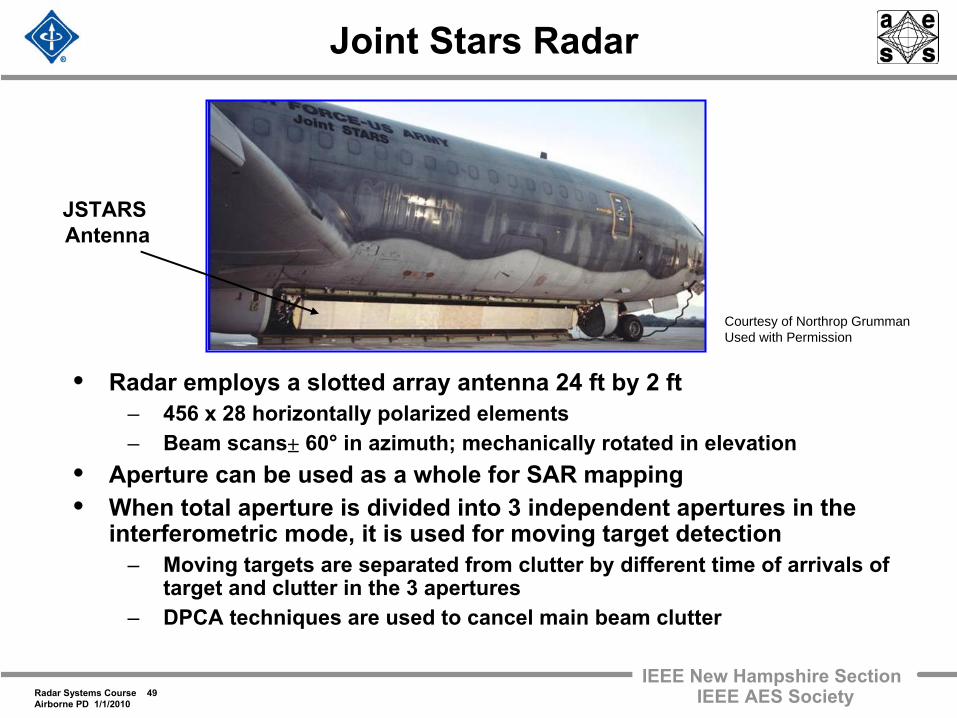
Joint Stars Radar
• Radar employs a slotted array antenna 24 ft by 2 ft– 456 x 28 horizontally polarized elements– Beam scans 60°
in azimuth; mechanically rotated in elevation• Aperture can be used as a whole for SAR mapping• When total aperture is divided into 3 independent apertures in the
interferometric mode, it is used for moving target detection– Moving targets are separated from clutter by different time of arrivals of
target and clutter in the 3 apertures– DPCA techniques are used to cancel main beam clutter
±
JSTARS Antenna
Courtesy of Northrop GrummanUsed with Permission
Radar Systems Course 50Airborne PD 1/1/2010
IEEE New Hampshire SectionIEEE AES Society
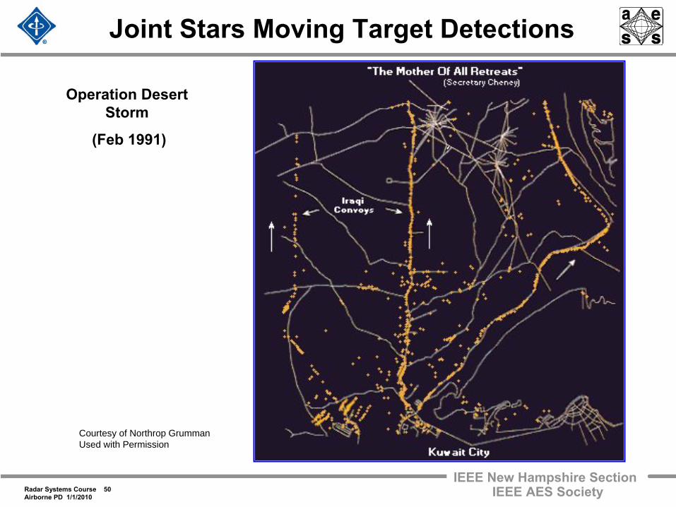
Joint Stars Moving Target Detections
Courtesy of Northrop GrummanUsed with Permission
Operation Desert Storm
(Feb 1991)
Radar Systems Course 51Airborne PD 1/1/2010
IEEE New Hampshire SectionIEEE AES Society
Outline
• Introduction– The airborne radar environment
• Different airborne radar missions– Pulse Doppler radar in small fighter / interceptor aircraft
F-14, F-15, F-16, F-35
– Airborne, surveillance, early warning radars E-2C (Hawkeye), E-3 (AWACS), E-8A (JOINT STARS)
– Airborne synthetic aperture radar SAR basics to be covered in lecture 19 Military and civilian remote sensing missions
To be covered in lecture 19, later in the course
• Summary
Radar Systems Course 52Airborne PD 1/1/2010
IEEE New Hampshire SectionIEEE AES Society
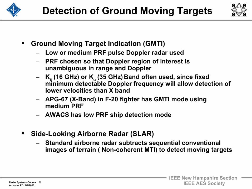
Detection of Ground Moving Targets
• Ground Moving Target Indication (GMTI)– Low or medium PRF pulse Doppler radar used– PRF chosen so that Doppler region of interest is
unambiguous in range and Doppler– Ku (16 GHz) or Kα (35 GHz)
Band often used, since fixed minimum detectable Doppler frequency will allow detection of lower velocities than X band
– APG-67 (X-Band) in F-20 fighter has GMTI mode using medium PRF
– AWACS has low PRF ship detection mode
• Side-Looking Airborne Radar (SLAR)– Standard airborne radar subtracts sequential conventional
images of terrain ( Non-coherent MTI) to detect moving targets
Radar Systems Course 53Airborne PD 1/1/2010
IEEE New Hampshire SectionIEEE AES Society
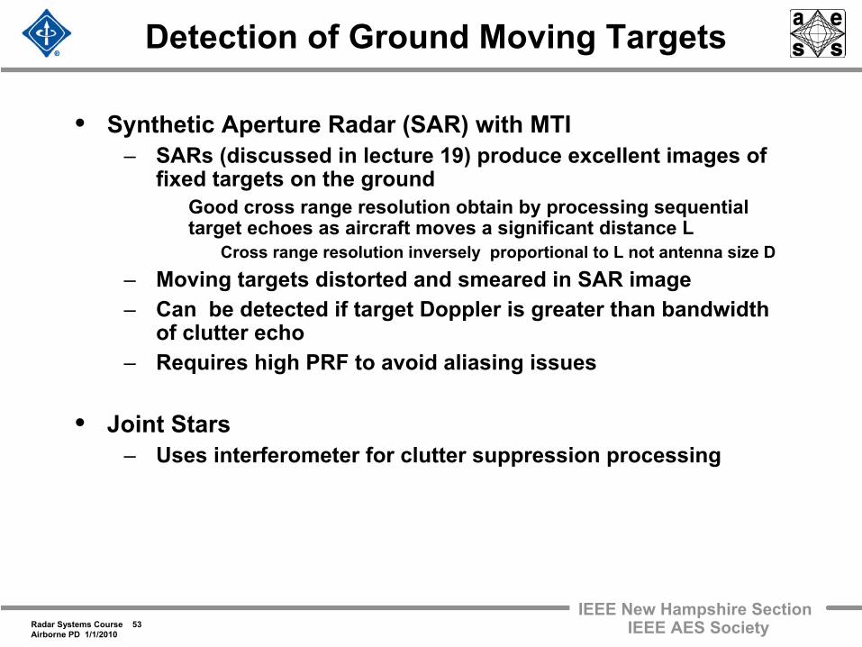
Detection of Ground Moving Targets
• Synthetic Aperture Radar (SAR) with MTI– SARs (discussed in lecture 19) produce excellent images of
fixed targets on the ground Good cross range resolution obtain by processing sequential
target echoes as aircraft moves a significant distance L Cross range resolution inversely proportional to L not antenna size D
– Moving targets distorted and smeared in SAR image– Can be detected if target Doppler is greater than bandwidth
of clutter echo– Requires high PRF to avoid aliasing issues
• Joint Stars– Uses interferometer for clutter suppression processing
Radar Systems Course 54Airborne PD 1/1/2010
IEEE New Hampshire SectionIEEE AES Society
Summary• Difficult ground clutter environment is chief radar design driver for
airborne radars– Elevated radar platform implies ground clutter at long range– Both Doppler frequency of clutter and its spread depend on radar
platform motion and scan angle
• Clutter challenges with Airborne radars– Antenna aperture size often limits frequencies, so that ambiguous
range and Doppler velocity issues arise Low, Medium and High PRF Modes each have unique clutter issues
– Doppler spreading of ground clutter, particularly at broadside, viewing can degrade performance
• Sophisticated clutter suppression techniques can alleviate some of these issues
– DPCA techniques– Medium and High PRF modes often imply higher power
• Active Electronically Scanned arrays and advanced signal processing techniques (STAP) offer significant new capabilities for airborne radars
Radar Systems Course 55Airborne PD 1/1/2010
IEEE New Hampshire SectionIEEE AES Society
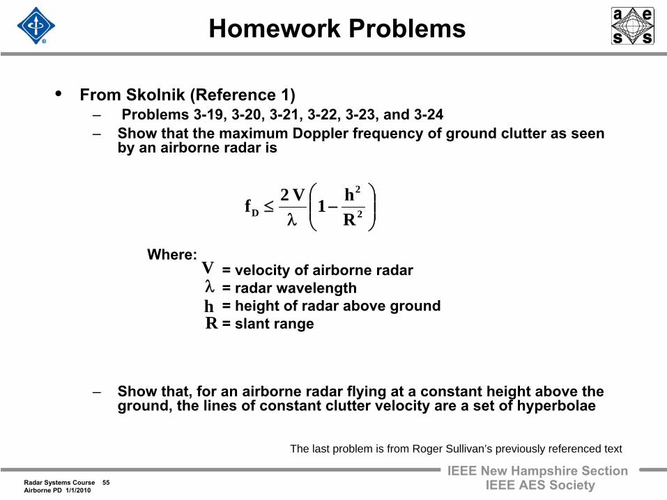
Homework Problems
• From Skolnik (Reference 1)– Problems 3-19, 3-20, 3-21, 3-22, 3-23, and 3-24– Show that the maximum Doppler frequency of ground clutter as seen
by an airborne radar is
– Show that, for an airborne radar flying at a constant height above the ground, the lines of constant clutter velocity are a set of hyperbolae
VWhere:
= velocity of airborne radar= radar wavelength= height of radar above ground= slant range
λhR
⎟⎟⎠
⎞⎜⎜⎝
⎛−
λ≤ 2
2
D Rh1V2f
The last problem is from Roger Sullivan’s previously referenced text
Radar Systems Course 56Airborne PD 1/1/2010
IEEE New Hampshire SectionIEEE AES Society
References
1. Skolnik, M., Introduction to Radar Systems, McGraw-Hill, New York, 3rd
Ed., 20012. Barton, D. K., Modern Radar System Analysis, Norwood,
Mass., Artech House, 19883. Skolnik, M., Editor in Chief, Radar Handbook, New York,
McGraw-Hill, 3rd
Ed., 20084. Skolnik, M., Editor in Chief, Radar Handbook, New York,
McGraw-Hill, 2nd
Ed., 19905. Nathanson, F. E., Radar Design Principles, New York,
McGraw-Hill, 1st
Ed., 19696. Richards, M., Fundamentals of Radar Signal Processing,
McGraw-Hill, New York, 20057. Schleher, D. C., MTI and Pulsed Doppler Radar, Artech,
Boston, 19918. Long, W. H., et. al, “Medium PRF for the AN/APG-66 Radar”,
Proceedings of the IEEE, Vol. 73, No 2, pp 301-311, February 1985
Radar Systems Course 57Airborne PD 1/1/2010
IEEE New Hampshire SectionIEEE AES Society
Acknowledgements
• Niall J. Duffy• Dr. Allen Hearn• Mark A. Weiner