Embed Size (px)
Citation preview

Graduate Student Symposium
Session Moderator:
Brandon Grainger – PhD Student
8th Annual Electric Power Industry Conference
University of Pittsburgh
Swanson School of Engineering
November 11th, 2013

DC and Hybrid Systems Analysis
Shimeng Huang
Augustin Cremer, Emmanuel Taylor
Ansel Barchowsky
8th Annual Electric Power Industry Conference
Swanson School of Engineering
Graduate Student Symposium
November 11th, 2013

Control of Multi-terminal DC Systems
Shimeng Huang
DC Data Center Design
Augustin Cremer, Emmanuel Taylor
Electric Power Systems Laboratory
Ansel Barchowsky
2

Multi-Terminal DC Controls
Prepared by: Shimeng Huang
Ph.D. Student
8th Annual Electric Power Industry Conference
Swanson School of Engineering
Graduate Student Symposium
November 11th, 2013

DC and Hybrid Systems Analysis
Multi-Terminal DC Controls
MTDC systems have great potential in transmission and distribution applications
4

DC and Hybrid Systems Analysis
• Research objective
Study interactions among controllers in a DC grid, develop a control design method that can coordinate local controllers to stabilize the grid and achieve optimal operation in system level
Multi-Terminal DC Controls
Control of MTDC systems involves trade-off between correlated control goals
5

DC and Hybrid Systems Analysis
Multi-Terminal DC Controls
Out state space modeling method is generalizable to arbitrary MTDC configurations
Subsystem
Coupling 0 2 4 6 8 10 12 14 16 18 20
0.85
0.9
0.95
1
i 12 (
pu)
0 2 4 6 8 10 12 14 16 18 200
0.5
1
i d (
pu)
id
id*
0 2 4 6 8 10 12 14 16 18 200.8
0.9
1
P1 (
pu)
P1
P1*
0 2 4 6 8 10 12 14 16 18 200.9
1
1.1
Udc1 (
pu)
Modal analysis :
• Identify critical modes and which states
are contributing to it
• Study how each system or control
parameter influences the damping of a
mode
• Extract simplified model in desired time
resolution for more detailed study.
6

DC and Hybrid Systems Analysis
Multi-Terminal DC Controls
Controller Design Method based on Linear Matrix Inequality (LMI) Optimization
Tune local controllers for
system performance
Add communication among controllers and compare
different topologies
Control and communication
co-design
Features: 1. Tuning control gains to stabilize
the grid as a whole 2. Able to set communication
structure to fit realistic infrastructure condition.
3. More flexibility on cost function
7
DC Data Center Design
Prepared by: Augustin Cremer, Masters Student, Emmanuel Taylor, PhD Student
8th Annual Electric Power Industry Conference
Swanson School of Engineering
Graduate Student Symposium
November 11th, 2013

DC and Hybrid Systems Analysis
DC Data Center Design
The need for computing power continues to increase.
9

DC and Hybrid Systems Analysis
DC Data Center Design
DC load growth has made DC distribution affordable.
10

DC load growth has made DC distribution affordable.
DC and Hybrid Systems Analysis
DC Data Center Design
10

380V DC is already used in datacenter design.
^ AC PSU DC PSU >
DC and Hybrid Systems Analysis
DC Data Center Design
11

» Emerge, shift to 380 V, why it makes sense, pdf dropbox
380V DC allows substantial savings on copper.
DC and Hybrid Systems Analysis
DC Data Center Design
12

Full DC facilities are becoming more prevalent, with higher power capacities
DC DATACENTER PROJECT LISTING
SYSTEM / PROJECT POWER RATING(kW) Voltage (V) Servers DC UPS/Rectifier Year LOCATION
1 Gnesta Municipality 9 350/380 2006 Gnesta, Sweden 2 Elicom 4.5 350 2006 Toreboda, Sweden 3 NTT NEDO Project 20 380 2007 Sendai, Japan 4 NTT University Microgrid 50 380 2007 Aichi, Japan 5 France Telecom 31.5 350/380 2007 Lannion, France 6 Ericsson 4.5 2008 Stockholm, Sweden 7 Soderhamm Teknikpark 6 350/380 2008 Soderhamn, Sweden 8 NTT Data Corp. 100 380 2009 Tokyo, Japan 9 NTT Lab. 100 380 2009 Tokyo, Japan
10 NTT Facilities 100 380 Intel 2009 Tokyo, Japan 11 Compare Test Lab 4.5 2009 Hammaro Karlstad, Sweden 12 Korea Telecom 300/380 2009 Seoul, Korea 13 UCSD 20 380 Oracle Sun Fire X4270, Intel 2600s Emerson 2009 San Diego, California
14 Syracuse University 150 380 2009 Syracuse, New York 15 Swedish Energy Agency 18 350 2010 Eskilstuna, Sweden 16 Compare Test Lab 500 350 2010 Hammaro Karlstad, Sweden 17 Duke Energy 30 380 HP DL 385 G7, IBM Power 795 Delta Products 2010 Charlotte, North Carolina 18 NTT East 100 380 2010 Tokyo, Japan 19 NTT 100 380 2011 Atsuigy City, Japan 20 Intel 400 21 Validus 550 22 China Telecom 240/380 23 China Mobile 380 24 ABB - Green 1000 380 HP DL 385 ABB 2012 Zurich, Switzerland
DC and Hybrid Systems Analysis
DC Data Center Design
13

DC distribution allows for easier and lower cost solar installation:
DC and Hybrid Systems Analysis
DC Data Center Design
14

Commercial solar installations typically interconnect to an AC system
DC and Hybrid Systems Analysis
DC Data Center Design
15

When the AC system is eliminated, the total facility impact is heightened
DC and Hybrid Systems Analysis
DC Data Center Design
15

This DC design concept will be realized through our partnership with PITT-OHIO
DC and Hybrid Systems Analysis
DC Data Center Design
16

The Electric Power Systems Lab
Prepared by: Ansel Barchowsky M.S. Student
8th Annual Electric Power Industry Conference
Swanson School of Engineering
Graduate Student Symposium
November 11th, 2013

DC Power Systems Research The Electric Power Systems Laboratory
– Train the next generation of power systems engineers
– Foster an environment for research at the highest level
Objective: Create a world class facility for hands-on education and research
18

DC Power Systems Research The Electric Power Systems Laboratory
Layout of the laboratory
Lab Benches
UPS
MCCs
IFS
Motors PV Inverter Capacitors
• Mix of Generation:
Grid, PV, Gas, Wind
• Variable system
strength
• Integrated laboratory
workbenches
• Motor Control Centers
• Advanced controls
• UPS and Datacenter
• Power factor correction
• 6 MHz metering
19

DC Power Systems Research The Electric Power Systems Laboratory
Contents:
• 4.5 kVA R, L, and C Loads
• 0.5 kVA Harmonic Load
• Touchscreen HMI PLC
• Motor Control Center
– 15-HP ATL or RVSS control
– 5-HP VFD control
• Auxiliary outlets (1 and 3 phase)
• Integrated Safety Features
Each bench was designed to incorporate controllable load banks and safety features
20
DC Power Systems Research The Electric Power Systems Laboratory
Complex topics can be explored, including:
• Distribution systems
• Power electronics
• Smart grids
• Energy storage
• Renewable energy
• Power quality
• Microgrids
The power systems laboratory can be used for a wide variety of applications:
21

Developing HVDC and FACTS Transmission Technologies
Patrick Lewis
Hashim Al Hassan
Alvaro Cardoza
8th Annual Electric Power Industry Conference
Swanson School of Engineering
Graduate Student Symposium
November 11th, 2013

Modeling and Protection Design Supporting HVDC Technology Development
Patrick Lewis and Hashim Al Hassan
Investigating FACTS Technologies in Weak AC Grid Environments
Alvaro Cardoza
2

Developing HVDC and FACTS Transmission Technologies
Prepared by: Patrick Lewis
M.S. Student
8th Annual Electric Power Industry Conference
Swanson School of Engineering
Graduate Student Symposium
November 11th, 2013

HVDC and FACTS Transmission Technologies Modular Multilevel HVDC Model Development
Role of the University of Pittsburgh within HVDC technology development project with Mitsubishi Electric Corporation
1. HVDC System Modeling 2. DC Fault Analysis 3. DC Protection System Design 4. DC Protective Relaying Schemes
1. AC System
2. Transformer
3. Converter 7. MMC composition 8. Sequence 4. DC Reactor
5. DC Line
6. Fault condition
System Ratings
Rated AC RMS Voltage 500 kV
Rated DC Voltage ± 500 kV
Rated Power of Converter 1000 MW
4

HVDC and FACTS Transmission Technologies Modular Multilevel HVDC Model Development
MMC Topology Design
• Advantages over traditional multilevel designs: – Stronger approximation of a
sinusoidal output – High modularity in hardware and
software – Low generation of harmonics – Lower switching frequency of
semiconductor devices – Easily scalable with increasing
submodules
Transformer
Arm reactance
Vdc
Cable
Cable
Submodule
Phase A Phase B Phase C
Vdc/2Phase A
Upper Arm
Phase A
Lower Arm
Ls
LsLs
Ls
Ls
Ls
Cell
Capacitor
Bypass
Switch
IGBTFWD
5

HVDC and FACTS Transmission Technologies Modular Multilevel HVDC Model Development
Model Implementation in PSCAD
• Goal: Demonstrate expected system functionality of the PSCAD model during both steady state operation and system events
AC Grid Voltage, Converter Output, and Reference
time 2.440 2.450 2.460 2.470 2.480 ...
...
...
-500
-400
-300
-200
-100
0
100
200
300
400
500
V [
kV]
Ea1 V1a1 Va_ref
AC Grid Voltage, Converter Output and Reference
6

HVDC and FACTS Transmission Technologies Modular Multilevel HVDC Model Development
Model Approximations and Considerations
• Simulation run time is of concern when modeling power electronic switching events making model approximations a necessity.
• System Model Simplified to 10 Cells Per Arm for Approximate Modeling
– IEEE 519-1992, a standard focused on harmonic limits and maximum THD levels, was used to determine the number of submodules to model.
– Standard Requirement: Maximum of 1.5% THD on the wye-side of transformer (AC grid side)
AC Voltage of WYE Side of Transformer 1
time 2.440 2.450 2.460 2.470 2.480 ...
...
...
-500
-400
-300
-200
-100
0
100
200
300
400
500
V (
line-t
o-n
eutr
al) [
kV]
Va_prim1 Vb_prim1 Vc_prim1
0.8% THD Level on Wye-Side (AC Side) of Transformer
7

HVDC and FACTS Transmission Technologies Modular Multilevel HVDC Model Development
Future Work
• Task 2: DC Fault Analysis
– Running DC fault case scenarios for the purpose of identifying worst case events to protect against
• Task 3: DC Protection System Design
– Problem: HVDC-MMC is vulnerable to DC faults
– Objective: Design a protection scheme that includes protection coordination and a strategy to address fault currents that cause stress on the converter devices
Single and Double Thyristor Design for Submodule Protection
8

Developing HVDC and FACTS Transmission Technologies
Prepared by: Hashim Al Hassan
M.S. Student
8th Annual Electric Power Industry Conference
Swanson School of Engineering
Graduate Student Symposium
November 11th, 2013

HVDC Protection Research
• Looking into methods of locating faults on hybrid DC systems including submarine cables and OH lines.
• Application System
– Offshore wind using HVDC VSC MMC
• Current fault location identification technology
– Fault locators
• Limitations of fault locators
– Potential Damage
– Unreliability on hybrid systems
– Cannot find location of temporary faults
HVDC and FACTS Transmission Technologies Section Identification & Location Identification of HVDC Faults
10

1. Fault section identification: instantly identify if the fault is on the cable or on the OH line
2. Fault location identification: use transient data recorded at the converter station terminal to identify exact location on hybrid system
Protection Coordination:
AC System 2
MMCAC System 1
MMC
Inverter Rectifier
CableOverhead
Line
Locating Faults without Fault Locator Technology:
HVDC and FACTS Transmission Technologies Section Identification & Location Identification of HVDC Faults
11

1. Fault Location Identification:
– Reduce maintenance time and cost.
– Prevent damage that may be caused by fault locators.
– Identify weak points in the system.(preventative maintenance)
Motivation of Research
2. Fault Section Identification:
– Increase Reliability by:
• Operating reclosers for OH line faults.
• Shutting down the system for cable faults.
HVDC and FACTS Transmission Technologies Section Identification & Location Identification of HVDC Faults
12

• The wave is reflected and refracted at a junction
Travelling Wave Theory: The method applied to research topic
Source: Allan Greenwood, Electrical Transients in Power Systems, Second edition, John
Wiley & Sons, Inc. 1991
HVDC and FACTS Transmission Technologies Section Identification & Location Identification of HVDC Faults
13

• Find a Surge Detection Method.
• Deal with complexity of the hybrid case
• Deal with uncertainty in wave velocity
Using Travelling Wave Theory
HVDC and FACTS Transmission Technologies Section Identification & Location Identification of HVDC Faults
14
Developing HVDC and FACTS Transmission Technologies
Prepared by: Alvaro Cardoza
M.S. Student
8th Annual Electric Power Industry Conference
Swanson School of Engineering
Graduate Student Symposium
November 11th, 2013

HVDC and FACTS Transmission Technologies Investigating FACTS in Weak AC Grid Environments
Project Description
• Exploration of Siemens’ new SVC PLUS ES
• Used to help alleviate a system’s weak grid conditions
– Weak grids occur when a system’s impedance is too high which does not allow for adequate current to flow
• PSS®E Simulation Software
– Main simulation tool for analysis
– Donated to the university by Siemens
16

Modified WECC 9-Bus Model
Synchronous Machine
Synchronous MachineHVDC Line
Type IV Aggregate
Wind Turbine Bus 2b Bus 2a Bus 7 Bus 8 Bus 9 Bus 3
Bus 6Bus 5
Bus 1 Bus 4
AC
DC
DC
AC
SVC PLUS ES
Modifications:
• HVDC Interconnecting Line • Type IV Aggregate Wind Turbine • SVC PLUS ES
HVDC and FACTS Transmission Technologies Investigating FACTS in Weak AC Grid Environments
17

SVC PLUS ES Technology
• SVC PLUS ES uses a full-bridge topology
• Energy storage is incorporated at every level
– Ultra capacitors
– Lithium ion batteries
• Tackles the issue of system inertia
HVDC and FACTS Transmission Technologies Investigating FACTS in Weak AC Grid Environments
Modularized Ultra Capacitor Example
18

Main Project Objectives
• How well does the SVC PLUS ES perform close to HVDC and/or weak grid conditions?
• How does the SVC PLUS ES design compare to alternative solutions?
• Identify applicable test cases within the United States for SVC PLUS ES technology.
HVDC and FACTS Transmission Technologies Investigating FACTS in Weak AC Grid Environments
19

Merits of High Frequency in Next Generation Power Electronics and Electric Machinery
Raghav Khanna
Qinhao Zhang
Oreste Scioscia
8th Annual Electric Power Industry Conference
Swanson School of Engineering
Graduate Student Symposium
November 11th, 2013

Wide Bandgap Semiconductors and Maximum Power Point Tracking
Raghav Khanna and Qinhao Zhang
Novel Magnetic Materials Utilized in Transformers and Electric Machinery
Oreste Scioscia 2

Merits of High Frequency in Next Generation Power Electronics and Electric Machinery
Prepared by: Raghav Khanna
Ph.D. Student
8th Annual Electric Power Industry Conference
Swanson School of Engineering
Graduate Student Symposium
November 11th, 2013

Merits of High Switching Frequency Enhancements in Semiconductor Technology
• High frequency operation in power converters will reduce the size and cost of renewable energy integrations.
– Transistor / MPPT Controller / Transformer
4

5
• Desired objectives for using GaN or SiC (WBGs) to replace Si:
– Reduce the size and potentially cost of power converter
• Higher operating switching frequency capability
• Faster turn-on and turn-off enables high switching frequency capability
– Increase operating efficiency
• Lower on-resistance
• Lower switching losses
– Eliminate mechanical support systems
• High temperature operation
• Ideal for renewable energy integrations.
Merits of High Switching Frequency Enhancements in Semiconductor Technology

• Lower parasitic capacitances for wide bandgap semiconductors enable faster switching.
Reported
Si FET
Reported
GaN FET Development of
GaN Device
Model
Development of
Si Device
Model
Merits of High Switching Frequency Enhancements in Semiconductor Technology
6

• Faster switching however can also lead to certain detrimental “dv/dt” effects.
Experimental
Modeled
Time (ns)
VD
S2
(V
) V
GS
2 (
V)
Merits of High Switching Frequency Enhancements in Semiconductor Technology
7

Merits of High Frequency in Next Generation Power Electronics and Electric Machinery
Prepared by: Qinhao Zhang
Ph.D. Student
8th Annual Electric Power Industry Conference
Swanson School of Engineering
Graduate Student Symposium
November 11th, 2013
9
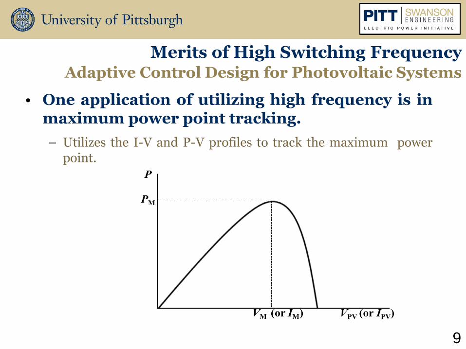
• One application of utilizing high frequency is in maximum power point tracking.
– Utilizes the I-V and P-V profiles to track the maximum power point.
Merits of High Switching Frequency Adaptive Control Design for Photovoltaic Systems

10
Merits of High Switching Frequency Adaptive Control Design for Photovoltaic Systems
Circuit Design
Topology of the circuit design: MPPT generates duty cycle
11
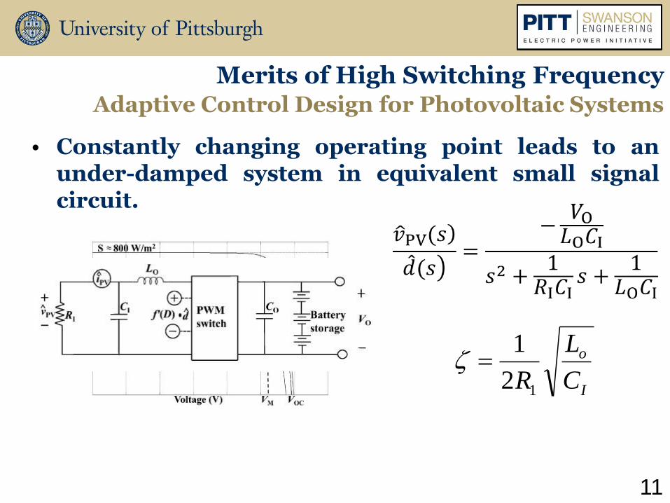
• Constantly changing operating point leads to an under-damped system in equivalent small signal circuit.
Merits of High Switching Frequency Adaptive Control Design for Photovoltaic Systems
I
o
C
L
R12
1

12
• Our proposed adaptive control algorithm will enable the system to converge to the MPP at high switching frequencies.
Adaptive Control Representation
Merits of High Switching Frequency Adaptive Control Design for Photovoltaic Systems

• Improved MPPT exhibits critically damped characteristic and smaller error
13
Merits of High Switching Frequency Adaptive Control Design for Photovoltaic Systems

Merits of High Frequency in Next Generation Power Electronics and Electric Machinery
Prepared by: Rusty Scioscia
M.S. Student
8th Annual Electric Power Industry Conference
Swanson School of Engineering
Graduate Student Symposium
November 11th, 2013

• Novel nanocrystalline material developed that has been proven to reduce magnetic cores of transformers by 60%.
15
Merits of High Switching Frequency Novel Magnetic Materials Utilized in Machine Design
Partners
Size Reduction Observed

• ANSYS Maxwell utilized to predict Steinmetz coefficients of magnetic materials.
16
Merits of High Switching Frequency Novel Magnetic Materials Utilized in Machine Design
Modeled Core
Core Loss vs. Frequency Characteristics
Simulated Core
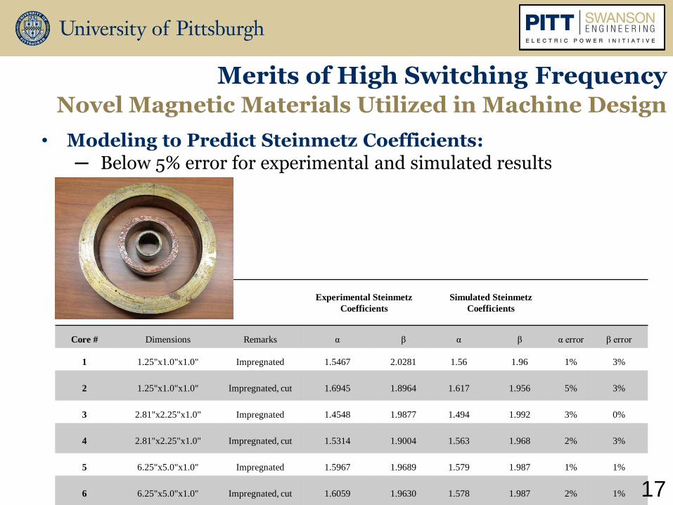
• Modeling to Predict Steinmetz Coefficients: ─ Below 5% error for experimental and simulated results
Merits of High Switching Frequency Novel Magnetic Materials Utilized in Machine Design
Experimental Steinmetz
Coefficients
Simulated Steinmetz
Coefficients
Core # Dimensions Remarks α β α β α error β error
1 1.25"x1.0"x1.0" Impregnated 1.5467 2.0281 1.56 1.96 1% 3%
2 1.25"x1.0"x1.0" Impregnated, cut 1.6945 1.8964 1.617 1.956 5% 3%
3 2.81"x2.25"x1.0" Impregnated 1.4548 1.9877 1.494 1.992 3% 0%
4 2.81"x2.25"x1.0" Impregnated, cut 1.5314 1.9004 1.563 1.968 2% 3%
5 6.25"x5.0"x1.0" Impregnated 1.5967 1.9689 1.579 1.987 1% 1%
6 6.25"x5.0"x1.0" Impregnated, cut 1.6059 1.9630 1.578 1.987 2% 1% 17

18
Merits of High Switching Frequency Novel Magnetic Materials Utilized in Machine Design
• Varying the driving frequency and the number of pole pairs while keeping the mechanical speed constant results in a 55 to 70% size reduction on motor geometry.
Field Strength for a 2 Pole Motor Design
Field Strength for a 16 Pole Optimized Motor Design

Methods and Approaches for Integrating Renewable Energy to an Evolving Grid
Matthew Korytowski
Laura Wieserman
Stephen Abate and Andrew Reiman
8th Annual Electric Power Industry Conference
Swanson School of Engineering
Graduate Student Symposium
November 11th, 2013

2
Integration of Offshore Wind Power to the U.S. Grid
Matthew Korytowski
PV Inverter Grounding
Laura Wieserman
Distribution Modeling for Feeder Analytics and Distributed Energy Resource (DER) Integration
Steve Abate and Andrew Reiman

Integration of Offshore Wind Power to the U.S. Grid
Prepared by: Matthew Korytowski
Ph.D. Student
8th Annual Electric Power Industry Conference
Swanson School of Engineering
Graduate Student Symposium
November 11th, 2013

Methods and Approaches for Integration Integration of Offshore Wind Power
Develop the technical and economic viability data necessary to produce a roadmap to the “20% Wind Energy by 2030” offshore goals
4
Task 4: Technology Assessments
Roadmap to DOE
“20% Wind Energy
by 2030” offshore
goals
Task 2: Wind
Production Profile
Development
Task 1: Offshore Wind
Development
Staging Projections
using ReEDS model &
updated EWITS data
Collector
Alternatives
AC v MVDC
Task 3: Initial Integration
Analysis
Assess Applicability of
Solution Sets
Delivery
Alternatives
AC v DC
Radial
Backbone
Grid
Cabling
Technologies
Installation
Marine
Substations
Design
Hardware
Regulatory
Concerns
Requirements
Cost Allocation

• ABB Power Systems Consulting
– Power systems studies, market analysis, power equipment
– Project lead and technology assessments
• University of Pittsburgh
– Electric Power Initiative, Department of Electrical Engineering
– Technology assessments and cost trends
• Xero Energy Limited
– Grid connection engineering consultant for renewable energy projects
– Technology assessments and cost trends
• AWS Truepower
– Renewable energy consulting and wind farm siting
– Wind resources, power production profiles
• National Renewable Energy Laboratory (NREL)
– Laboratory for renewables research and development
– Wind development staging, study method assessment
• Duke Energy
– Generation and transmission owner
– Regulatory issues assessment
5
Methods and Approaches for Integration Integration of Offshore Wind Power
There are six other companies involved to achieve the desired goals

6
Methods and Approaches for Integration Integration of Offshore Wind Power
Task 1: Determine the expected offshore wind development staging
ReEDS 2030 Build-out progression

7
Methods and Approaches for Integration Integration of Offshore Wind Power
– Develop synthetic power output profiles for theoretical offshore wind plants
– 209 Sites Totaling 134+ GW
– Site Totals By Region: All ReEDS Targets Met or Exceeded
Task 2: Determine the wind generation production profiles

8
Methods and Approaches for Integration Integration of Offshore Wind Power
Task 3: Assess the applicability of onshore wind integration study methods to offshore wind studies
Methods to be assessed: Potential improvements:
Eastern Wind Integration and Transmission Study (EWITS)
Improved offshore wind data sets
Western Wind and Solar Integration Study (WWSIS)
Improved utility system production modeling
Energy Imbalance Market (EIM) analysis Larger balancing regions provided by offshore grid

9
Methods and Approaches for Integration Integration of Offshore Wind Power
1. What options are currently available?
2. What new options are possible (but not implemented) with current technology?
3. What options could be made available with foreseeable technological advancements (and what advancements are needed)?
4. What are the benefits and drawbacks of each possible technology option?
5. What are the economics of each option?
Wind
Turbines
Platforms
Cables
Generation Collection Delivery
Cables
Grid
Interconnection
Equipment
Task 4: Assessment of present-day cost trends and technologies

Photovoltaic Inverter Grounding
Prepared by: Laura Wieserman
M.S. Student
8th Annual Electric Power Industry Conference
Swanson School of Engineering
Graduate Student Symposium
November 11th, 2013

11
Methods and Approaches for Integration PV Inverter Grounding
R. Bravo, R. Yinger, S. Robles, W. Tamae, “Solar PV Inverter Testing for Model Validation”,
IEEE PES General Meeting, Detroit, MI, July 25, 2011.
Inverter Testing

12
jX0 (system)
I0
System SLGF
jX2total
DG
jX1 (system)
jX2 (system)
C0 line
C0 line
C0 line
Loop 1
Loop 2
jX1total
jX0total
I1
I2
Zero
Positive
Negative
Utility
Inverter Modeling
– Starting with superposition to show contribution of the PV inverter to the fault current and overvoltage using symmetrical components
Methods and Approaches for Integration PV Inverter Grounding

13
PhiladelphiaElectric
SubstationTransformer (s)
System Modeling
– Modeling Navy Yard facility in PSCAD and MATLAB
Methods and Approaches for Integration PV Inverter Grounding

14
Methods and Approaches for Integration PV Inverter Grounding
System Testing
– Aggregating PV sources
Correlated Voltage Variations Uncorrelated Voltage Variations
Distribution Feeder

15
Methods and Approaches for Integration PV Inverter Grounding
New Lab Instrumentation
Access to DC and AC
inverter terminals
4kW PV Panels on the roof of Benedum Hall
PV Simulator
PV Simulator Software
Electric Power Systems Lab
Distribution Modeling for Feeder Analytics and Distributed Energy Resource (DER) Integration
Prepared by: Stephen Abate
Andrew Reiman
M.S. Students
8th Annual Electric Power Industry Conference
Swanson School of Engineering
Graduate Student Symposium
November 11th, 2013

17
Methods and Approaches for Integration Distribution Modeling for Feeder Analytics
Basic systems can be modeled using traditional methods
17
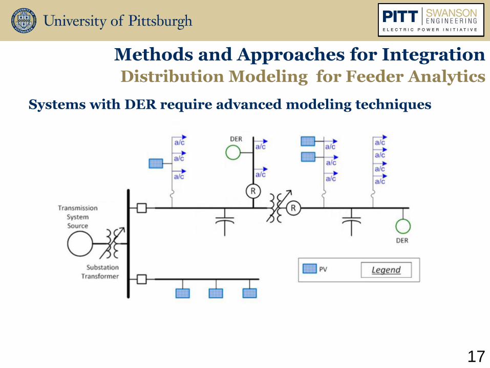
Methods and Approaches for Integration Distribution Modeling for Feeder Analytics
Systems with DER require advanced modeling techniques

17
Methods and Approaches for Integration Distribution Modeling for Feeder Analytics
Sensors are used to validate advanced modeling techniques

18
Methods and Approaches for Integration Distribution Modeling for Feeder Analytics
Open Distribution System Simulator (OpenDSS)
– Flexible open source software
– Time domain analysis (yearly, daily, duty cycle simulations)
– COM Interface (MATLAB, Excel, VBA, Python, etc)
– Ideal for importing data
– Repetitive scripted solutions
– Models smart grid components (DER, Storage, AMI)

Methods and Approaches for Integration Distribution Modeling for Feeder Analytics
OpenDSS models can be created from a variety of different data sources with scripted methods
OpenDSS model
GIS extracts
GIS equipment catalog
Feeder sensor measurements
Equipment test reports
19

20
Methods and Approaches for Integration Distribution Modeling for Feeder Analytics
OpenDSS - Poplar Feeder Model

21
Methods and Approaches for Integration Distribution Modeling for Feeder Analytics
Research Goals
– Create detailed visualizations
– Use non-linear interpolation techniques to analyze non-synchronous data samples
– Estimate states of grid devices including switches and capacitor banks
– Perform real-time acquisition of data and metrics

Thank You