Embed Size (px)
Citation preview

04/19/23 1
VLSI Physical Design Automation
Prof. David Pan
Office: ACES 5.434
Lecture 6. Floorplanning (1)

204/19/23
Hierarchical Design
• Several blocks after partitioning:
• Need to:– Put the blocks together.– Design each block.
Which step to go first?

304/19/23
Hierarchical Design
• How to put the blocks together without knowing their shapes and the positions of the I/O pins?
• If we design the blocks first, those blocks may not be able to form a tight packing.

404/19/23
Floorplanning
The floorplanning problem is to plan the positions and shapes of the modules at the beginning of the design cycle to optimize the circuit performance:– chip area– total wirelength– delay of critical path– routability– others, e.g., noise, heat dissipation, etc.
504/19/23
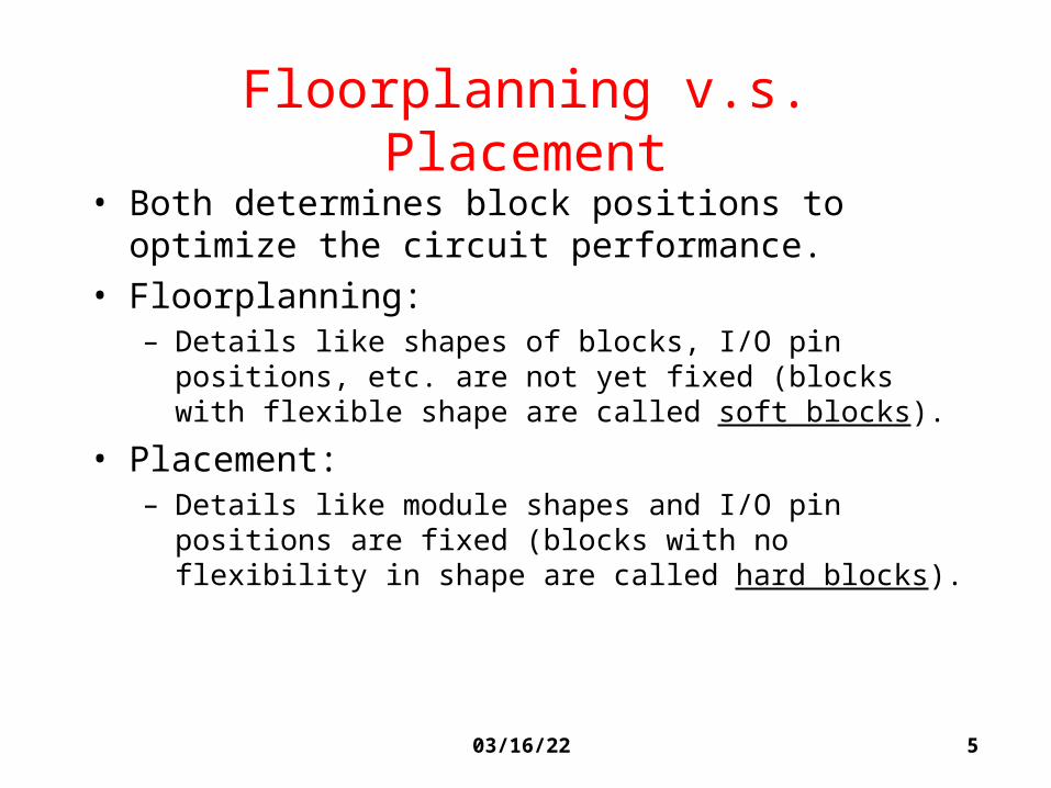
Floorplanning v.s. Placement
• Both determines block positions to optimize the circuit performance.
• Floorplanning:– Details like shapes of blocks, I/O pin positions, etc. are not yet
fixed (blocks with flexible shape are called soft blocks).
• Placement:– Details like module shapes and I/O pin positions are fixed
(blocks with no flexibility in shape are called hard blocks).
604/19/23
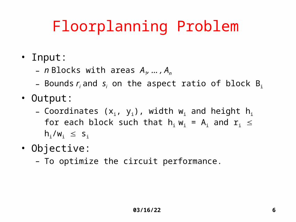
Floorplanning Problem
• Input:– n Blocks with areas A1, ... , An
– Bounds ri and si on the aspect ratio of block Bi
• Output:– Coordinates (xi, yi), width wi and height hi for each block such
that hi wi = Ai and ri hi/wi si
• Objective:– To optimize the circuit performance.

704/19/23
Bounds on Aspect Ratios
If there is no bound on the aspect ratios, can we pack everything tightly? - Sure!
But we don’t want to layout blocks as long strips, so we require ri hi/wi si for each i.

804/19/23
Bounds on Aspect Ratios
• We can also allow several shapes for each block:
• For hard blocks, the orientations can be changed:

904/19/23
Objective Function
A commonly used objective function is a weighted sum of area and wirelength:
cost = A + L
where A is the total area of the packing, L is the total wirelength, and and are constants.

1004/19/23
Wirelength Estimation
• Exact wirelength of each net is not known until routing is done.
• In floorplanning, even pin positions are not known yet.• Some possible wirelength estimations:
– Center-to-center estimation– Half-perimeter estimation
1104/19/23
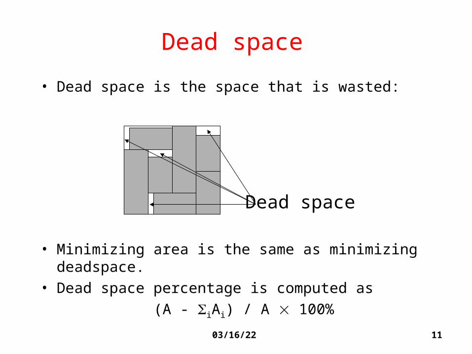
Dead space
• Dead space is the space that is wasted:
• Minimizing area is the same as minimizing deadspace. • Dead space percentage is computed as
(A - iAi) / A 100%
Dead space

1204/19/23
Slicing and Non-Slicing Floorplan
• Slicing Floorplan: One that can be obtained by repetitively subdividing (slicing) rectangles horizontally or vertically.
• Non-Slicing Floorplan:One that may not be obtained by repetitively subdividing alone.
• Otten (LSSS-82) pointed out that slicing floorplans are much easier to handle.

1304/19/23
Polar Graph Representation
• A graph representation of floorplan.• Each floorplan is modeled by a pair of directed
acyclic graphs:– Horizontal polar graph– Vertical polar graph
• For horizontal (vertical) polar graph,– Vertex: Vertical (horizontal) channel– Edge: 2 channels are on 2 sides of a block– Edge weight: Width (height) of the block
Note: There are many other graph representations.

1404/19/23
Polar Graph: Example
Horizontal Polar Graph
Vertical P
olar Graph

04/19/23 15
Simulated Annealing using Polish Expression Representation
Simulated Annealing using Polish Expression Representation
D.F. Wong and C.L. Liu,D.F. Wong and C.L. Liu,““A New Algorithm for Floorplan DesignA New Algorithm for Floorplan Design””
DAC, 1986, pages 101-107.DAC, 1986, pages 101-107.

1604/19/23
Representation of Slicing Floorplan
62
3
54
7
1
Slicing FloorplanV
H H
2 1 3H
V
6 4
V
7 5
Slicing Tree
Polish Expression(postorder traversal
of slicing tree) 21H67V45VH3HV

1704/19/23
Polish Expression
• Succinct representation of slicing floorplan– roughly specifying relative positions of blocks
• Postorder traversal of slicing tree1. Postorder traversal of left sub-tree
2. Postorder traversal of right sub-tree
3. The label of the current root
• For n blocks, a Polish Expression contains n operands (blocks) and n-1 operators (H, V).
• However, for a given slicing floorplan, the corresponding slicing tree (and hence polish expression) is not unique. Therefore, there is some redundancy in the representation.

1804/19/23
Skewed ST and Normalized PE• Skewed Slicing Tree:
– no node and its right son are the same.• Normalized Polish Expression:
– no consecutive H’s or V’s.
62
3
54
7
1
Slicing FloorplanV
H H
2 1 3H
V
6 4
V
7 5
Slicing Tree (Skewed)
Polish Expression 21H67V45VH3HV
V
H H
2 1 HV
6 V7 3
Slicing Tree
4 5
21H67V45V3HHV

1904/19/23
Normalized Polish Expression
• There is a 1-1 correspondence between Slicing Floorplan, Skewed Slicing Tree, and Normalized Polish Expression.
• Will use Normalized Polish Expression to represent slicing floorplans.– What is a valid NPE?
• Can be formulated as a state space search problem.
2004/19/23
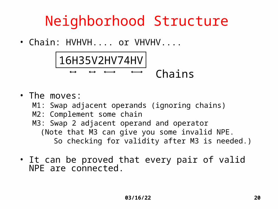
Neighborhood Structure• Chain: HVHVH.... or VHVHV....
• The moves:M1: Swap adjacent operands (ignoring chains)M2: Complement some chainM3: Swap 2 adjacent operand and operator
(Note that M3 can give you some invalid NPE. So checking for validity after M3 is needed.)
• It can be proved that every pair of valid NPE are connected.
16H35V2HV74HVChains

2104/19/23
Example of Moves
2
1
543
34V2H5V1H
14
3 25
32V4H5V1H
1
5
423
32V45HV1H
1
4 5
3 2
32V45VH1H
M1
M3
M2

2204/19/23
Shape Curve• To represent the possible shapes of a block.
w
h
(0,0)
wh = A
Soft block Block with several existing design
w
h
(0,0)
Feasibleregion
Feasibleregion
2304/19/23
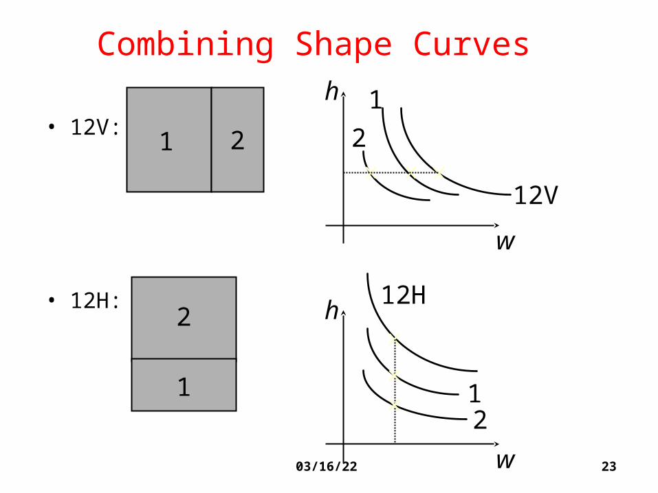
Combining Shape Curves
• 12V:
• 12H:
1 2
h
w
12V
1
2
2
1
w
h
21
12H

2404/19/23
Find the Best Area for a NPE
• Recursively combining shape curves.
V
23
Pick thebest
1
2
31
H

2504/19/23
Updating Shape Curves after Moves
• If keeping k points for each shape curve, time for shape curve computation for each NPE is O(kn).
• After each move, there is only small change in the floorplan. So there is no need to start shape curve computation from scratch.
• We can update shape curves incrementally after each move.
• Run time is about O(k log n).

2604/19/23
Initial Solution
• 12V3V4V...nV
2 31 .... n

2704/19/23
Annealing Schedule
• Ti = Ti-1 where =0.85
• At each temperature, try k x n moves
(k is around 5 to 10)• Terminate the annealing process if
– either # of accepted moves < 5%– or the temperate is low enough

04/19/23 28
Handling both Rectangular and L-Shaped Blocks
Handling both Rectangular and L-Shaped Blocks
D.F. Wong and C.L. Liu,D.F. Wong and C.L. Liu,““Floorplan Design for Rectangular Floorplan Design for Rectangular
and L-Shaped Modulesand L-Shaped Modules””ICCAD, 1987, pages 520-523.ICCAD, 1987, pages 520-523.

2904/19/23
Rectangular and L-Shaped Blocks• Possible shapes:
• Note that L-shaped blocks can be produced even if we start with rectangular blocks only.
• Can even generate non-slicing floorplans.

3004/19/23
Basic Idea
• Similar to the DAC-86 paper by Wong & Liu:– Polish Expression representation.– Simple moves to locally modify floorplan.– Simulated Annealing.
• Differences from the DAC-86 paper:– 5 operators and 4 moves defined to handle the more complex
shapes.– Idea of shape curves no longer applicable.– Depend on Simulated Annealing to pick different shapes for
blocks probabilistically.
3104/19/23
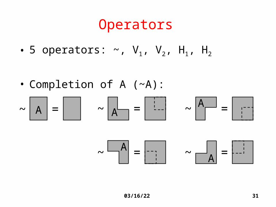
Operators
• 5 operators: ~, V1, V2, H1, H2
• Completion of A (~A):
~ = ~ = ~ =
~ = ~ =
A AA
AA

3204/19/23
Binary Operators V1, V2, H1 and H2
• Need to define what “A op B” means,
where A and B are rectangular or L-shaped blocks, op is V1, V2, H1 or H2.
• Total # of ways to combine 2 blocks
= 5 x 4 x 5 = 100

3304/19/23
Example of Combining 2 Blocks
• Several possible outcomes. Represented as:
V1 =A B A B A B A Bor or
V2 =A B A B A B A Bor or
V1 =A B A B
V2 =A B A B

3404/19/23
Another Example of Combining
H1 =B
H2 =B or or
A AB
A AB
AB
AB
Represented as:
AB

3504/19/23
Moves
• Write the Polish Expression in the form:
b1u1b2u2 ... b2n-1u2n-1
where bi’s are the n blocks, or the n-1 binary operators, and each ui is either ~ or the empty string .
• The moves:
M1: Modify for some i (change to a different shape or a different binary operator).
M2: Change ui to ~ or for some i.
M3: Swap 2 blocks bi and bj.
M4: Swap bi and bi+1 for some i.
(M4 can obtain invalid PE. Checking needed.)

3604/19/23
Another Classic Work
“Optimal Orientation of Cells in Slicing floorplan Designs”
L. Stockmeyer, Information and Control 57(1983), 91-101
- This is an earlier paper than [Wong-Liu’86], dealing with simpler problem
- Given slicing structure and a set of module shapes (or shape list)
- How to orient these modules such that the total area is smallest?
8x117x13
AB
C
DE
5 8
42
3 2
53
8 5
A B
C
DE
5
4 7
2
3
3
6
6
5
2

3704/19/23
Difficulty
v
2
v
2
4
2
v
2
4
16
m1•m2 choices
m1m2

3804/19/23
Key Idea
• Dynamic programming– Compute a set of irredundant solutions at each
sub-tree rooted from the list of irredundant solutions for its two child subtrees
– Pick the best solution from the list of irredundant solutions at the root

3904/19/23
Example of Merging: only keep irredundant solutions

4004/19/23
Stockmeyer Algorithm

4104/19/23
Stockmeyer Algorithm (Cont’d)

4204/19/23
Complexity of the Algorithm
n= # of leaves = 2 * # of modules
d=depth of the tree
Running time= O(nd)
Storage = O(n)
because, at depth k, sum of the lengths of the lists =O(n) time to construct these lists =O(n) configurations stored at this node can be
release as soon as the node is processed
Extension
Each module has k possible shapes
Running time and storage O(nkd)
depth k

4304/19/23
Summary: What’s BIG idea?
• Floorplan problem is definitely NP hard • How to represent it compactly is a big deal.• Slicing is easier to deal with, so let’s start with it• Polish expression is very elegant and easy to make
new moves– Need to be unique (NPE)– Bounding curve for area computation when merging two
blocks, which can be computed incrementally
• For a given set of modules and the slicing tree, Stockmeyer’s algorithm can give the optimal solution– But it’s a very ideal situation that doesn’t happen often – Nice algorithm using dynamic programming