Embed Size (px)
Citation preview

306817NEN
Instructions/Parts
10:1 President Pump Hydra-Clean® Units
For mounting on open 55 gallon supply drum. May be wall-mounted with accessory bracket. For professional use only.
Model 6880119, Series C (PTFE Packings)Model 206515, Series C (Neoprene Packings)
7 MPa, (69 bar, 1000 psi) Maximum Working Pressure
0.7 MPa, (7 bar, 100 psi) Maximum Incoming Air Pressure
• Stainless steel pump and spray valve handle powerful clean solutions at high pressure.
• Divorced design pump—keeps cleaning solution from fouling air motor.
• Accumulator reduces line pulses—air charged at the factory.
• Air line lubricator for automatic lubrication of air motor.
• Suction tube has intake filter.
Solution volume and working pressure can be adjusted using a different tip orifice size and an air regulator. Fan pattern can be changed to concentrating jet stream using blasting tip.
Important Safety InstructionsRead all warnings and instructions in this manual before using the equipment. Save these instructions.

2 306817N
ContentsWarnings . . . . . . . . . . . . . . . . . . . . . . . . . . . . . . . . . . 3Setup . . . . . . . . . . . . . . . . . . . . . . . . . . . . . . . . . . . . . 6
Grounding . . . . . . . . . . . . . . . . . . . . . . . . . . . . . . 6General Information . . . . . . . . . . . . . . . . . . . . . . . 6Connect Hoses and Mount Pump . . . . . . . . . . . . 7
Operation. . . . . . . . . . . . . . . . . . . . . . . . . . . . . . . . . . 8Pressure Relief Procedure. . . . . . . . . . . . . . . . . . 8Before Using . . . . . . . . . . . . . . . . . . . . . . . . . . . . 8Useful Hints . . . . . . . . . . . . . . . . . . . . . . . . . . . . . 9Shutdown and Care of Unit . . . . . . . . . . . . . . . . . 9
Troubleshooting . . . . . . . . . . . . . . . . . . . . . . . . . . . 10Service . . . . . . . . . . . . . . . . . . . . . . . . . . . . . . . . . . . 11
General. . . . . . . . . . . . . . . . . . . . . . . . . . . . . . . . 11Accumulator Repair . . . . . . . . . . . . . . . . . . . . . . 11
Accessories. . . . . . . . . . . . . . . . . . . . . . . . . . . . . . . 11Stainless Steel Spray Tips . . . . . . . . . . . . . . . . . 11
Parts . . . . . . . . . . . . . . . . . . . . . . . . . . . . . . . . . . . . . 12Dimensions . . . . . . . . . . . . . . . . . . . . . . . . . . . . . . . 14Technical Specifications . . . . . . . . . . . . . . . . . . . . 15Graco Standard Warranty . . . . . . . . . . . . . . . . . . . 16

Warnings
306817N 3
WarningsThe following warnings are for the setup, use, grounding, maintenance, and repair of this equipment. The exclamation point symbol alerts you to a general warning and the hazard symbols refer to procedure-specific risks. When these symbols appear in the body of this manual or on warning labels, refer back to these Warnings. Product-specific hazard symbols and warnings not covered in this section may appear throughout the body of this manual where applicable.
WARNINGEQUIPMENT MISUSE HAZARD
Equipment misuse can cause the equipment to rupture or malfunction and result in serious injury.
Use this pump only for pumping water and water--diluted cleaning solutions in a pressure washing system. Never use the pump for paint or any other coatings. Any misapplication of the pump may cause dangerous operating conditions which can result in serious injury and substantial property damage.
• This equipment is for professional use only.• Read all instruction manuals, tags, and labels before operating the equipment.• Use the equipment only for its intended purpose. If you are not sure, call your Graco distributor.• Do not alter or modify this equipment. Use only Graco parts and accessories.• Check equipment daily. Repair or replace worn or damaged parts immediately.• Do not exceed the maximum working pressure stated on the equipment or in the Technical Data for
your equipment. Do not exceed the maximum working pressure of the lowest rated component in your system.
• Use fluids and solvents which are compatible with the equipment wetted parts. Refer to the Technical Data section of all equipment manuals. Read the fluid and solvent manufacturer’s warnings.
• Handle hoses carefully. Do not pull on hoses to move equipment.• Route hoses away from traffic areas, sharp edges, moving parts, and hot surfaces. Do not expose
Graco hoses to temperatures above 66°C (150°F) or below -40°C (-40°F).• Wear hearing protection when operating this equipment.• Do not move or lift pressurized equipment.• Comply with all applicable local, state, and national fire, electrical, and safety regulations.

Warnings
4 306817N
SKIN INJECTION HAZARDSpray from the gun, hose leaks, or ruptured components can inject fluid into your body and cause an extremely serious injury, including the need for amputation. Splashing fluid in the eyes or on the skin can also cause a serious injury.
• Fluid injected into the skin might look like just a cut, but it is a serious injury. Get immediate medical attention.
• Do not point the spray gun at anyone or at any part of the body.• Do not put hand or fingers over the spray tip.• Do not stop or deflect fluid leaks with your hand, body, glove, or rag.• Do not “blow back” fluid; this is not an air spray system.• Always have the tip guard and the trigger guard on the spray gun when spraying.• Check the gun diffuser operation weekly. Refer to the gun manual.• Be sure the gun trigger safety operates before spraying.• Lock the gun trigger safety when you stop spraying.• Follow the Pressure Relief Procedure on page 6 whenever you: are instructed to relieve pressure;
stop spraying; clean, check, or service the equipment; and install or clean the spray tip.• Tighten all the fluid connections before operating the equipment.• Check the hoses, tubes, and couplings daily. Replace worn, damaged, or loose parts immediately.
Do not repair high pressure couplings; replace the entire hose.• Fluid hoses must have spring guards on both ends, to help protect them from rupture caused by kinks
or bends near the couplings.
MOVING PARTS HAZARDMoving parts, such as the air motor piston, can pinch or amputate your fingers.
• Keep clear of all moving parts when starting or operating the pump.• Never operate the pump with the air motor plates removed.• Before checking or servicing the equipment, follow the Pressure Relief Procedure to prevent the
equipment from starting unexpectedly.
WARNING

Warnings
306817N 5
FIRE AND EXPLOSION HAZARDImproper grounding, poor ventilation, open flames or sparks can cause a hazardous condition and result in a fire or explosion and serious injury.
• Ground the equipment and the object being sprayed. See Grounding. • If there is any static sparking or you feel an electric shock while using this equipment, stop spraying
immediately. Do not use the equipment until you identify and correct the problem.• Provide fresh air ventilation to avoid the buildup of flammable fumes from solvents or the fluid being
sprayed.• Keep the spray area free of debris, including solvent, rags, and gasoline.• Before operating this equipment, electrically disconnect all equipment in the spray area.• Before operating this equipment, extinguish all open flames or pilot lights in the spray area.• Do not smoke in the spray area.• Do not turn on or off any light switch in the spray area while spraying or while operating if fumes are
present.• Do not operate a gasoline engine in the spray area.
TOXIC FLUID OR FUMES HAZARDHazardous fluid or toxic fumes can cause serious injury or death if splashed in the eyes or on the skin, inhaled, or swallowed.
• Know the specific hazards of the fluid you are using.• Store hazardous fluid in an approved container. Dispose of hazardous fluid according to all local,
state and national guidelines.• Always wear protective eyewear, gloves, clothing and respirator as recommended by the fluid and
solvent manufacturer.
WARNING

Setup
6 306817N
Setup
Grounding
Although water generally provides a natural electrical ground, the following equipment must be grounded if the cleaning chemical are volatile.
1. When cleaning in enclosed areas, such as storage tanks, locate the pump and air compressor outside the area and well away from it. Provide adequate ventilation. If the area you are cleaning has stored flammable materials. take appropriate precautions to avoid static sparking. Consul your local codes.
2. Pump: use a ground wire and clamp. See FIG. 1 Loosen the grounding lug locknut (W) and washer
(X). Insert one end of a 1.5 mm2 (12 ga) minimum ground wire (Y) into the slot in lug (Z) and tighten the locknut securely. Connect the other end of the wire to a true earth ground. Order Part No. 237569 Ground Wire and Clamp.
FIG. 1
3. Air and fluid hoses: use only electrically conductive hoses.
4. Air compressor: follow manufacturer’s recommendations.
5. Spray gun: ground through connection to a properly grounded fluid hose and pump.
6. Fluid supply container: follow your local code.
7. Object being sprayed: follow your local code.
8. Solvent pails used when flushing: follow your local code. Use only metal pails, which are conductive, placed on a grounded surface. Do not place the pail on a nonconductive surface, such as paper or cardboard, which interrupts the grounding continuity.
9. To maintain grounding continuity when flushing or relieving pressure, hold a metal part of the spray gun firmly to the side of a grounded metal pail, then trigger the gun.
General InformationThe typical setup shown in FIG. 2 is only a guide to selecting and installing required and optional components. For assistance in designing a system to suit your needs, contact your Graco distributor. Refer to FIG. 2 for callouts in parentheses.
Before operating the pump, ground the system as explained below. Also read the section FIREAND EXPLOSION HAZARD on page 5.
Y
W
X
Z

Setup
306817N 7
Connect Hoses and Mount Pump1. Using Loctite Pipe Sealant, screw the hose stud
(10) of the suction hose into the pump’s intake housing. See FIG. 2. Remove one of the screws from the pump base opposite the outlet, and assemble the hanging bracket (19) to the pump with the provided screw (9)—use the lockwasher that was on the replaced screw.
2. Using Loctite® Pipe Sealant, screw the accumulator (7) inlet adapter into the pump outlet. Connect the fluid hose to the accumulator, the nozzle to the spray valve, and the air line lubricator (3) to the pump air inlet. Hang the pump on your cleaning solution drum. NOTE: The filter on the suction hose should be about 1/2 in. (12.7 mm) off the bottom of the drum. If the hose is too long, cut it off as necessary.
3. Close the air ball valve (24), then connect your 1/2 ID (min) air supply hose to the 1/2 nptm(f) inlet union (15)—do not use thread sealer. Install an accessory air filter and water separator to remove excessive moisture that could cause air motor icing. Pour high quality SAE 10 into the lubricator until oil reaches the level mark on the sight glass.
NOTICE
Oils containing phosphate ester or chlorinated hydro-carbons are not compatible with the plastic bowl of the lubricator—be sure that oil used to lubricate the compressor is free of these additives.

Operation
8 306817N
Operation
Pressure Relief ProcedureFollow the Pressure Relief Procedure whenever you see this symbol.
1. Lock the Hydra-Clean® gun trigger safety.
2. Close the pump air regulator.
3. Close the red handled bleed-type master air valve (required in your system)
4. Unlock the gun trigger safety and trigger the gun to relieve pressure.
5. Lock the gun trigger safety.
6. Open the pump drain valve, having a container ready to catch the drainage.
7. Leave the drain valve open until you are ready to spray again.
If you suspect that the dispensing valve, extension, or grease fitting coupler is clogged, or that pressure has not been fully relieved after following the steps above, VERY SLOWLY loosen the coupler or hose end coupling and relieve pressure gradually, then loosen completely, now clear the clog.
Before UsingPrepare cleaning solution as instructed, observing all safety precautions. Pre-mix powered cleaners in a separate bucket of hot water before adding to water in the supply drum.
See FIG. 2. Open the main air supply valve, hold the spray valve open and slowly open the air petcock until the pump is running slowly. After solution is coming from the spray nozzle, open the ball valve (24) all the way and adjust the air line lubricator (3) to deliver about one drop per minute. Refer to the separate lubricator instruction manual.
Release the spray valve trigger and let the pump run. The pump will charge the accumulator with liquid pressure, then stall.
NOTE: Protect surfaces that might be damaged by the cleaning solution and rinse before the solution dries on both surfaces. You can clean stubborn dirt off better with a stronger, heated solution.
WARNINGTo avoid serious injury, including fluid injection and splashing in the eyes or on the skin, never point the gun at yourself or anyone else.
Fluid under high pressure can be injected through the skin and cause serious injury. To reduce the risk of an injury from injection, splashing fluid, or moving parts, follow the Pressure Relief Procedure whenever you:
• are instructed to relieve the pressure,• stop spraying,• check or service any of the system equipment,• or install or clean the spray nozzles.
WARNINGTake care not to get spray containing cleaning chemicals into your eyes, ears, or nose. If any spray does get on your skin or in your eyes, flush immediately and thoroughly with water. Seek immediate medical attention.

Operation
306817N 9
Useful Hints
Hold the spray nozzle about 2 feet (0.6 m) from the surface and completely mist-wet the object you are cleaning. Let it soak briefly, then use the spray to “chisel” the dirt off—keep the nozzle about 6 in. (152.4 mm) from, and at an angle to the surface. If some dirt remains, wet the surface again. Let the object soak a little longer, then hold the nozzle as close as possible and spray to blast the dirt off.
FIG. 2
After all the dirt is cleaned off, rinse all the solution off with clear, cold water. When you are through cleaning, close the air petcock and follow the Pressure Relief Procedure, page 8.
Shutdown and Care of Unit
When shutting down for the day or weekend, shut off the main air supply and relieve the pressure. Rinse all solution off the equipment with clear, cold water, Shut off the water supply valve and relieve the water pressure.
Check the air line lubricator (3) often and keep it filled with oil. Also check the pump packing nut regularly and keep it just tight enough to stop leakage, but no tighter. Use a 1/4 in. diameter rod to tighten.
WARNINGTo reduce the risk of serious injury whenever you are instructed to relieve pressure, always follow the Pressure Relief Procedure, page 8.
6018b
34
9
19
16
10
1
7
24
3
15
NOTICE
Do not allow the pump to run dry. It will quickly accel-erate to a high speed, causing damage. If your pump is running too fast, stop it immediately and check the fluid supply. If the container is empty and air has been pumped into the lines, refill the container and prime the pump and the lines, or flush and leave it filled with a compatible solvent. Eliminate all air from the fluid system.
WARNINGTo reduce the risk of serious injury whenever you are instructed to relieve pressure, always follow the Pressure Relief Procedure, page 8.

Troubleshooting
10 306817N
Troubleshooting1. Follow Pressure Relief Procedure, page 8, before
checking or repairing the equipment
2. Check all possible problems and causes before disassembling the equipment.
Problem Cause Solution
Excessive surge at spray nozzle Obstructed spray tip, valve, or hose Clean, clear
Cleaning solution supply empty Refill
Accumulator not working Recharge—see Service on page 11 and manual 306933
Clogged intake filter, kinked or collapsed suction hose
Clean, unkink
Fluid leaking from valve Loose packing nut or worn packings See manual 307010
Valve will not stop dispensing Valve not adjusted properly See manual 307010
Dirty or worn valve stem or seat Clean, clear, or replace—See manual 307010
Valve will not stop the pump Cleaning solution supply empty Refill
Clogged intake filter, kinked or collapsed suction hose
Clean, unkink
Dirty or worn valve stem or seat Clean clear, or replace—See manual307010
Dirty or worn fluid piston or packings Service—See manual 308117
Pump operating, but spray pressure low on up stroke.
Dirty or worn fluid piston or packings Service—See manual 308117
Pump operating, but spray pressure low on down stroke
Dirty or worn fluid intake valve Clean, clear, or replace—See manual 308117
Pump operating, but spray pressure low on both strokes
Clogged intake filter, kinked or collapsed suction hose
Clean, unkink
Dirty or worn fluid piston or packings Service—See manual 308117
Dirty or worn fluid intake valve Clean, clear, or replace—See manual 308117
Loose packing nut or worn packings Tighten, replace—See manual 308117
Fluid will not come from pump (hose removed)
Restricted air line Check for closed valve; use larger supply hose
Pump throat packing nut too tight Loosen
Pump air motor not working Service—See manual 306982
System will not spray Restricted air line Check for closed valve; use larger supply hose
Pump air motor not working Service—See manual 306982
Service
306817N 11
Service
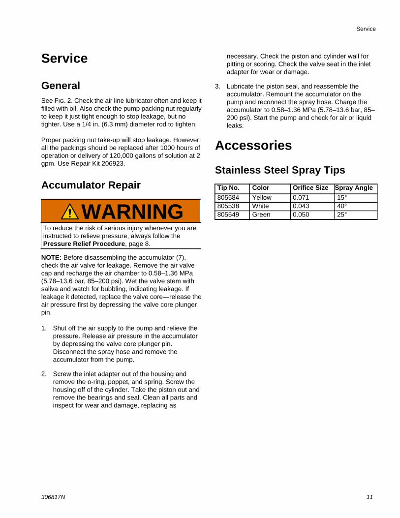
GeneralSee FIG. 2. Check the air line lubricator often and keep it filled with oil. Also check the pump packing nut regularly to keep it just tight enough to stop leakage, but no tighter. Use a 1/4 in. (6.3 mm) diameter rod to tighten.
Proper packing nut take-up will stop leakage. However, all the packings should be replaced after 1000 hours of operation or delivery of 120,000 gallons of solution at 2 gpm. Use Repair Kit 206923.
Accumulator Repair
NOTE: Before disassembling the accumulator (7), check the air valve for leakage. Remove the air valve cap and recharge the air chamber to 0.58–1.36 MPa (5.78–13.6 bar, 85–200 psi). Wet the valve stem with saliva and watch for bubbling, indicating leakage. If leakage it detected, replace the valve core—release the air pressure first by depressing the valve core plunger pin.
1. Shut off the air supply to the pump and relieve the pressure. Release air pressure in the accumulator by depressing the valve core plunger pin. Disconnect the spray hose and remove the accumulator from the pump.
2. Screw the inlet adapter out of the housing and remove the o-ring, poppet, and spring. Screw the housing off of the cylinder. Take the piston out and remove the bearings and seal. Clean all parts and inspect for wear and damage, replacing as
necessary. Check the piston and cylinder wall for pitting or scoring. Check the valve seat in the inlet adapter for wear or damage.
3. Lubricate the piston seal, and reassemble the accumulator. Remount the accumulator on the pump and reconnect the spray hose. Charge the accumulator to 0.58–1.36 MPa (5.78–13.6 bar, 85–200 psi). Start the pump and check for air or liquid leaks.
Accessories
Stainless Steel Spray Tips
WARNINGTo reduce the risk of serious injury whenever you are instructed to relieve pressure, always follow the Pressure Relief Procedure, page 8.
Tip No. Color Orifice Size Spray Angle
805584 Yellow 0.071 15°805538 White 0.043 40°805549 Green 0.050 25°

Parts
12 306817N
Parts
FIG. 3: Model 206515 President Hydra-Clean
15
3
2423
37
31
11
34
9
19
32
16
18
4
5
7
38
1
6
10
8
39

Parts
306817N 13
Parts List for Models 206515 and 6880119 President Hydra-Clean
Ref. Part No. Description Qty.
1 18A826 HOSE, coupled, high press, 40 ft (12 m)
1
3 214847 AIR LINE LUBRICATOR 1
4 206300 SUCTION HOSE FILTER 1
5 224346 10:1 PRESIDENT PUMP, for pressure washing UHMWPE/Neoprene packed Stainless Steel Hydra-Clean Pumps (See manual 308117 for parts)
1
224342 10:1 PRESIDENT PUMP, for severe duty UHMWPE/PTFE or PTFE packed Stainless Steel Pumps (See manual 308116 for parts)
1
6 247879 SPRAY GUN (See manual 307010 for parts)
1
7 207278 AIR CHARGED ACCUMULATOR (See manual 306933 for parts)
2
8 102123 CLAMP, hose 1
9 102235 CAPSCREW, hex hd; 1/4-20 x 1/2 in.
1
10 102550 STUD, barbed hose; 3/8 npt(m) 1
11 158256 UNION, swivel; 1/2 nptf x 3/8 npsm
1
15 162505 UNION, str swivel; 3/8 npt(m) x 1.2 npt(f) swivel
1
16 162802 HOSE, plastic; 3/4 in. ID; 24 in. (0.6 m) long
1
18 164085 SPRING, reinforcing 1
19 165280 BRACKET, pump mounting 1
23 108066 TEE; 1.4 npt(f) 1
24 113333 BLEED-TYPE AIR VALVE, red handled
1
31 113498 VALVE, air relief 1
32 237569 GROUND WIRE 1
34 102024 WASHER, lock 1
37 100176 BUSHING, hex 1
38 235208 UNION, swivel 1
39 15T278 SWIVEL, adapter, 3/8 in.-18 npt, MA 3/8 QR, SST
1
Ref. Part No. Description Qty.

Dimensions
14 306817N
Dimensions
1/2 npt air inlet
28-3/16 in. (715 mm)
14-3/4 in.(375 mm)

Technical Specifications
306817N 15
Technical Specifications
California Proposition 65
10:1 President Pump Hydra-Clean® UnitsUS Metric
Air pressure operating range 20 to 120 psi 1.5 to 8.5 bar (150 to 850 kPa)Pump ratio 10:1Recommended cycle rate for continuous duty 60 cycles per minute, or 3 gpmPump discharge pressure 1200 psi) 83 bar, 8.3 MPaAir volume requirements
Without spray tip23 cfm at 70 psi 0.64 m3/minute
at 4.8 bar (480 kPa)
With 0.062 in. spray tip, included with unit32 cfm at 100 psi 0.90 m3/minute
at 6.9 bar (690 kPa)WeightAll models 55 lb 24.95 kgNoise (dBa)
Sound pressure level* 83 dBa at 100 psi (6.8 bar, 0.68 MPa)—40 cycles/minute (at one meter)
Sound power level** 96 dBa at 100 psi (6.8 bar, 0.68 MPa)—40 cycles/minute*Sound pressure measured 3.37 feet (1 meter) from equipment.
**Sound power measured per ISO-9614-2.
CALIFORNIA RESIDENTS
WARNING: Cancer and reproductive harm – www.P65warnings.ca.gov.
All written and visual data contained in this document reflects the latest product information available at the time of publication. Graco reserves the right to make changes at any time without notice.
Original instructions. This manual contains English. MM 306817Graco Headquarters: Minneapolis
International Offices: Belgium, China, Japan, Korea
GRACO INC. AND SUBSIDIARIES • P.O. BOX 1441 • MINNEAPOLIS MN 55440-1441 • USACopyright 2020, Graco Inc. All Graco manufacturing locations are registered to ISO 9001.
www.graco.comRevision N, November 2020
Graco Standard WarrantyGraco warrants all equipment referenced in this document which is manufactured by Graco and bearing its name to be free from defects in material and workmanship on the date of sale to the original purchaser for use. With the exception of any special, extended, or limited warranty published by Graco, Graco will, for a period of twelve months from the date of sale, repair or replace any part of the equipment determined by Graco to be defective. This warranty applies only when the equipment is installed, operated and maintained in accordance with Graco’s written recommendations.
This warranty does not cover, and Graco shall not be liable for general wear and tear, or any malfunction, damage or wear caused by faulty installation, misapplication, abrasion, corrosion, inadequate or improper maintenance, negligence, accident, tampering, or substitution of non-Graco component parts. Nor shall Graco be liable for malfunction, damage or wear caused by the incompatibility of Graco equipment with structures, accessories, equipment or materials not supplied by Graco, or the improper design, manufacture, installation, operation or maintenance of structures, accessories, equipment or materials not supplied by Graco.
This warranty is conditioned upon the prepaid return of the equipment claimed to be defective to an authorized Graco distributor for verification of the claimed defect. If the claimed defect is verified, Graco will repair or replace free of charge any defective parts. The equipment will be returned to the original purchaser transportation prepaid. If inspection of the equipment does not disclose any defect in material or workmanship, repairs will be made at a reasonable charge, which charges may include the costs of parts, labor, and transportation.
THIS WARRANTY IS EXCLUSIVE, AND IS IN LIEU OF ANY OTHER WARRANTIES, EXPRESS OR IMPLIED, INCLUDING BUT NOT LIMITED TO WARRANTY OF MERCHANTABILITY OR WARRANTY OF FITNESS FOR A PARTICULAR PURPOSE.
Graco’s sole obligation and buyer’s sole remedy for any breach of warranty shall be as set forth above. The buyer agrees that no other remedy (including, but not limited to, incidental or consequential damages for lost profits, lost sales, injury to person or property, or any other incidental or consequential loss) shall be available. Any action for breach of warranty must be brought within two (2) years of the date of sale.
GRACO MAKES NO WARRANTY, AND DISCLAIMS ALL IMPLIED WARRANTIES OF MERCHANTABILITY AND FITNESS FOR A PARTICULAR PURPOSE, IN CONNECTION WITH ACCESSORIES, EQUIPMENT, MATERIALS OR COMPONENTS SOLD BUT NOT MANUFACTURED BY GRACO. These items sold, but not manufactured by Graco (such as electric motors, switches, hose, etc.), are subject to the warranty, if any, of their manufacturer. Graco will provide purchaser with reasonable assistance in making any claim for breach of these warranties.
In no event will Graco be liable for indirect, incidental, special or consequential damages resulting from Graco supplying equipment hereunder, or the furnishing, performance, or use of any products or other goods sold hereto, whether due to a breach of contract, breach of warranty, the negligence of Graco, or otherwise.
FOR GRACO CANADA CUSTOMERS The Parties acknowledge that they have required that the present document, as well as all documents, notices and legal proceedings entered into, given or instituted pursuant hereto or relating directly or indirectly hereto, be drawn up in English. Les parties reconnaissent avoir convenu que la rédaction du présente document sera en Anglais, ainsi que tous documents, avis et procédures judiciaires exécutés, donnés ou intentés, à la suite de ou en rapport, directement ou indirectement, avec les procédures concernées.
Graco InformationFor the latest information about Graco products, visit www.graco.com.For patent information, see www.graco.com/patents.TO PLACE AN ORDER, contact your Graco distributor or call to identify the nearest distributor.Phone: 612-623-6921 or Toll Free: 1-800-328-0211, Fax: 612-378-3505