Embed Size (px)
Citation preview

INSTRUCTIONS–PARTS LIST 307–399Rev. K
Supersedes Rev. J
AIR–POWERED MONARK PUMP
Variable Ratio Hydra-Cat � Proportioning Pump180 psi (12 bar) Maximum Working Air Pressure
Model 226–930, Series B0.9:1 to 3.4:1 Variable Ratio Range
Model 226–931, Series C2.9:1 to 10.0:1 Variable Ratio Range
Model 226–932, Series C4.9:1 to 18.0:1 Variable Ratio Range
GRACO INC. P.O. BOX 1441 MINNEAPOLIS, MN 55440–1441�COPYRIGHT 1980, GRACO INC.
This manual contains important warnings and information. READ AND RETAIN FOR REFERENCE
������

��������
Table of ContentsSymbols 3. . . . . . . . . . . . . . . . . . . . . . . . . . . . . . . . . . . . . . Definition of Terms 3. . . . . . . . . . . . . . . . . . . . . . . . . . . . . Warnings 3. . . . . . . . . . . . . . . . . . . . . . . . . . . . . . . . . . . . . . Specifications of Monark Hydra-Cat Pumps 6. . . . . . . . Installation 6. . . . . . . . . . . . . . . . . . . . . . . . . . . . . . . . . . . .
Connect the Reducer Supply Line 6. . . . . . . . . . . . . . Connect the Fluid Supply Lines 6. . . . . . . . . . . . . . . . Connect the Static Mixer to the Manifold 6. . . . . . . . System Accessories 7. . . . . . . . . . . . . . . . . . . . . . . . . . Connect the Air Supply Line 7. . . . . . . . . . . . . . . . . . . Pressure Relief Valve 7. . . . . . . . . . . . . . . . . . . . . . . . . Electrical Grounding 8. . . . . . . . . . . . . . . . . . . . . . . . . .
Ratio Adjustment 9. . . . . . . . . . . . . . . . . . . . . . . . . . . . . . . Terms 9. . . . . . . . . . . . . . . . . . . . . . . . . . . . . . . . . . . . . . .
Determine the Ratio 10. . . . . . . . . . . . . . . . . . . . . . . . . . . Procedure 1: Base is pre–reduced 10. . . . . . . . . . . . . Procedure 2: Reducer injection by a third
displacement pump (by ratio) 10. . . . . . . . . . . . . . . Procedure 3: Reducer injection by a third
displacement pump (by percentage) 10. . . . . . . . . Set the Ratio 11. . . . . . . . . . . . . . . . . . . . . . . . . . . . . . . . .
Pump Specifications Chart 11. . . . . . . . . . . . . . . . . . . Relationship Between the Primary and
Secondary Pumps 11. . . . . . . . . . . . . . . . . . . . . . . . . Calculate the Ratio Setting 12. . . . . . . . . . . . . . . . . . . . .
Ratio Setting Chart 1 (Model 226–930) 12. . . . . . . . . Ratio Setting Chart 2 (Model 226–931) 13. . . . . . . . . Ratio Setting Chart 3 (Model 226–932) 13. . . . . . . . .
Setting the Secondary Pump(s) 13. . . . . . . . . . . . . . . . . Operation 14. . . . . . . . . . . . . . . . . . . . . . . . . . . . . . . . . . . .
Pressure Relief Procedure 14. . . . . . . . . . . . . . . . . . . . System Flushing 14. . . . . . . . . . . . . . . . . . . . . . . . . . . .
Start the Pump 14. . . . . . . . . . . . . . . . . . . . . . . . . . . . . . Standard Operating Flushing 14. . . . . . . . . . . . . . . . . Checking the Ratio 15. . . . . . . . . . . . . . . . . . . . . . . . . .
Troubleshooting 16. . . . . . . . . . . . . . . . . . . . . . . . . . . . . . . Troubleshooting Techniques 16. . . . . . . . . . . . . . . . . . To isolate the problem 16. . . . . . . . . . . . . . . . . . . . . . . Troubleshooting Chart 16. . . . . . . . . . . . . . . . . . . . . . .
Service 17. . . . . . . . . . . . . . . . . . . . . . . . . . . . . . . . . . . . . . Tools Needed 17. . . . . . . . . . . . . . . . . . . . . . . . . . . . . . . Bearing and Pump Lubrication 18. . . . . . . . . . . . . . . . Air Lubrication 18. . . . . . . . . . . . . . . . . . . . . . . . . . . . . . Detecting the Bearing and Pin Wear 16. . . . . . . . . . . Removing the Lever Arm from the VRHC Frame 18Finding Which Pin Or Bearing Is Worn 19. . . . . . . . . Fitting the Pins into the Bearings 19. . . . . . . . . . . . . . Storage of Spare Pins and Bearings 19. . . . . . . . . . . Removing the Secondary Pump and/or the
Bearings and Pins 20. . . . . . . . . . . . . . . . . . . . . . . . . Replacing the Secondary Pump and/or the
Bearing Pins 21. . . . . . . . . . . . . . . . . . . . . . . . . . . . . . Removing the Primary Pump and/or the
Lower Bearing and Pin 22. . . . . . . . . . . . . . . . . . . . Replacing the Primary Pump and/or
Bearing and Pins 24. . . . . . . . . . . . . . . . . . . . . . . . . Replacing the Lever Arm on the Frame 25. . . . . . . .
Parts 26. . . . . . . . . . . . . . . . . . . . . . . . . . . . . . . . . . . . . . . . Accessories 32. . . . . . . . . . . . . . . . . . . . . . . . . . . . . . . . . . Dimensions 34. . . . . . . . . . . . . . . . . . . . . . . . . . . . . . . . . . . Air Consumption 34. . . . . . . . . . . . . . . . . . . . . . . . . . . . . . Technical Data 35. . . . . . . . . . . . . . . . . . . . . . . . . . . . . . . . Graco Phone Numbers 36. . . . . . . . . . . . . . . . . . . . . . . . . The Graco Warranty and Disclaimers 36. . . . . . . . . . . .

������� �
SymbolsWarning Symbol
WARNING�his symbol alerts you to the possibility of seriousinjury or death if you do not follow the instructions.
Caution Symbol
CAUTIONThis symbol alerts you to the possibility of damage toor destruction of equipment if you do not follow theinstructions.
Definition of TermsWARNING: Alerts the user to avoid or correct condi-tions which could cause serious injury.
CAUTION: Alerts the user to avoid or correct condi-tions which could damage or destroy equipment.
NOTE: Identifies helpful information.
VRHC: The abbreviation for Variable Ratio Hydra-CatPump. This pump automatically proportions and mixestwo or three fluids in a prescribed ratio, which is vari-able within the ranges listed on the cover.
BASE: Also called polyol or resin, is one of two reac-tive chemicals used in a plural component system.
CATALYST: Also called hardener, is the fluid whichreacts with the base fluid.
PART: An undefined unit of measurement. When youdetermine the size of the unit (ounce, pint, gallon), usethat measurement consistently in setting up your sys-tem.
SPRAY GUN: This term refers to any type of spraygun or dispensing valve used to spray or dispense thefluid being pumped.
PLURAL COMPONENT FLUID HAZARDBefore using this equipment, read the fluid manufacturer’s warnings and determine all facts relatingto the fluids used, including any of the potential hazards relating to toxic fumes, fires, explosions,reaction times, and exposure of human beings to the individual components of their resultant mix-tures.
� Store hazardous fluid in an approved container. Dispose of hazardous fluid according to all local,state and national guidelines.
� Wear the appropriate protective clothing, gloves, eyewear and respirator.
� Graco does not manufacture or supply any of the reactive chemical components that may beused in this equipment and is not responsible for their effects. Graco assumes no responsibilityfor loss, damage, expense or claims for personal injury or property damage, direct or consequen-tial, arising from the use of such chemical components.
MOVING PARTS HAZARDMoving parts, such as the air motor piston and the secondary pump lever and connecting rod area,can pinch or amputate fingers.
� Do not operate the equipment with the air motor plates removed.
� Keep your body and tools clear of any moving parts when starting or operating the equipment.
WARNINGWARNING

��������
FIRE AND EXPLOSION HAZARDImproper grounding, poor air ventilation, open flames, or sparks can cause a hazardous conditionand result in fire or explosion and serious injury.
� Ground the equipment and the object being sprayed. See Electrical Grounding on page 8.
� Provide fresh air ventilation to avoid the buildup of flammable fumes from solvent or the fluid be-ing sprayed.
� Extinguish all the open flames or pilot lights in the spray area.
� Electrically disconnect all the equipment in the spray area.
� Keep the spray area free of debris, including solvent, rags, and gasoline.
� Do not turn on or off any light switch in the spray area while operating or if fumes are present.
� Do not smoke in the spray area.
� Do not operate a gasoline engine in the spray area.
� If there is any static sparking while using the equipment, stop spraying immediately . Identifyand correct the problem.
EQUIPMENT MISUSE HAZARDEquipment misuse can cause the equipment to rupture, malfunction, or start unexpectedly and resultin serious injury.
� This equipment is for professional use only.
� Read all instruction manuals, tags, and labels before operating the equipment.
� Use the equipment only for its intended purpose. If you are uncertain about the usage, call GracoTechnical Assistance at 1–800–543–0339.
� Do not alter or modify this equipment. Use only genuine Graco parts and accessories.
� Check the equipment daily. Repair or replace worn or damaged parts immediately.
� All system components must meet or exceed the pressure ratings printed on the pressure reliefvalve. The lever amplification or the secondary pump enables very high fluid pressures to beachieved. A 475 to 575 psi working pressure range relief valve is provided on the secondary sideto limit the fluid pressure. Do not tamper with this pressure relief valve or serious bodily injurycould result.
� Do not lift pressurized equipment.
� Route the hoses away from the traffic areas, sharp edges, moving parts, and hot surfaces. Donot expose Graco hoses to temperatures above 180�F (82�C) or below –40�F (–40�C).
� Do not use the hoses to pull the equipment.
� Use fluids or solvents that are compatible with the equipment wetted parts. See the TechnicalData section of all the equipment manuals. Read the fluid and solvent manufacturer’s warnings.
� Fluid hoses must have spring guards on both ends to protect them from rupture caused by kinksor bends near the couplings.
� Comply with all applicable local, state and national fire, electrical and other safety regulations.
WARNINGWARNING
INSTRUCTIONS

������� �
INJECTION HAZARDSpray from the spray gun, hose leaks or ruptured components can inject fluid into your body andcause extremely serious injury, including the need for amputation. Splashing fluid in the eyes or onthe skin can also cause can also cause serious injury.
� Fluid injected into the skin might look like just a cut, but it is a serious injury. Get immediatemedical attention.
� Do not point the spray gun at anyone or any part of the body.
� Do not put hand or fingers over the spray tip.
� Do not stop or deflect fluid leaks with your hand, body, glove or rag.
� Do not “blow back” fluid; this is not an air spray system.
� Always have the tip guard and the trigger guard on the spray gun (if so equipped) when spraying.
� Check the spray gun diffuser (if so equipped) operation weekly. Refer to the gun manual.
� Be sure the spray gun trigger safety operates before operating the gun.
� Lock the spray gun trigger safety when you stop spraying.
� Follow the Pressure Relief Procedure on page 14 when you are instructed to relieve pressure,stop spraying, check, clean or service any system equipment, or install or change spray tips.
� Tighten all fluid connections before each use.
� Check the hoses, tubes and couplings daily. Replace worn or damaged parts immediately. Per-manently coupled hoses cannot be repaired.
� Handle and route hoses and tubes carefully. Keep hoses and tubes away from moving parts andhot surfaces. Do not use the hoses to pull equipment. Do not expose Graco hoses to tempera-tures above 180�F (82�C) or below –40�F (–40�C).
WARNINGWARNING

��������
Specifications of Monark Hydra-Cat PumpsThe following chart gives specifications for the MonarkHydra–Cat pumps, using No. 10 weight oil. The volu-metric ratio is expressed as the proportion of the vol-ume of fluid of the primary pump compared to the vol-ume of fluid of the secondary pump.
For example, Model 226–930 has a maximum volu-metric ratio of 0.9:1. At this setting the primary andsecondary pumps combined will deliver an output of2.8 gpm (10.6 liter/min). The minimum volumetric ratiofor Model 226–930 is 3.4:1 and the combined output atthat setting is 1.8 gpm (6.8 liters/min).
ModelNumber
Pump Volumetric RatioAdjustment
Output Volumegpm (liter/min)
at 40 cpm
Stall Pressure with 100 psi (6.8 bar)
Inbound pressureNumber Primary Secondary Maximum Minimum Maximum Minimum Maximum Minimum
226–930226–931226–932
215–932215–932215–932
215–932222–015222–019
0.9:12.9:14.9:1
3.4:110:118:1
2.8 (10.6)1.8 (6.8)1.6 (6)
1.8 (6.8)1.5 (5.7)1.4 (5.3)
170 (11)260 (17)310 (29)
280 (19)320 (22)360 (24)
InstallationThe Typical Installation shown above is only a guide tosetting up the complete VRHC system. For assistancein designing a system to suit your particular needs,contact your nearest Graco representative or theGraco Fluid Technology Unit, 9451 West Belmont,Franklin Park, Illinois 60131; (708) 678–7200.
NOTE: The reference numbers and letters in the text cor-respond to the numbers and letters in the drawings.
LocationSit the proportioner on a flat floor surface.
Connect the Solvent Flush Supply LineRemove the safety panels (38, 39, 40). See Fig. 1.Connect a grounded fluid hose (U) from the solventflush pump to the 3/8 npt reducer inlet (M) of the mixermanifold.
Connect the Fluid Supply LinesConnect the grounded fluid hoses to the 3/4 npt(f)pump inlet fittings (P, R). If the unit will be pressure fedfrom separate supply units, install a fluid pressuregauge at each inlet.
NOTE: The pressurized fluid supplies must not exceed1/4 of the operating fluid pressure of the pump. Pres-sure above that level will feed right through the pumpand improper rationing will result.
Connect the Static Mixer to the ManifoldConnect a static mixer (N) to the 1/2 npt(m) manifoldoutlet. Connect a electrically conductive fluid hose andspray gun to the end of the static mixer.
Tighten all of the fittings. Install the safety panels (38,39, 40). See Fig. 1.
Fig. 1 ������
40
EE
GG
38
AA
46
DDFF
39BB
HH CC
KEY
AA Primary pumpBB Secondary pumpCC Ratio adjustment clampDD Manifold leverEE Solvent valves
FF Mixer manifoldGG Sampling valvesHH Lever arm38, 39, 40 Panels46 Pressure relief valve

������� �
Installation
Fig. 2
�����
V T
GG
FE
H
K J U
P
123 124
R
LU
ÎÎ
N
S
45
8
46
M
13106
120
119
KEY
E Air supply lineF Airline filter, P/N 106–149G Air shutoff valveH Air line lubricator, P/N 214–848J Base supply pressure potK Hardener supply pressure potL Solvent flush supply pressure potM Mixer manifold solvent flush inlet
N Static mixerP Primary pump inletR Secondary pump inletS Nitrogen supplyT Spray gunU Grounded fluid hosesV Air pressure regulator for the spray gun8 Air pressure gauge
13 Air regulator45 Bleed–type master air valve46 Pressure relief valve106 Pressure gauge119 Sampling valves120 Mixer manifold123 Primary proportioning pump124 Secondary proportioning pump
System AccessoriesRefer to Fig. 2 and to Accessories on page 32.
NOTE: To ensure the maximum pump performance,be sure that all the accessories used are properlysized to meet your system requirements. Use onlygenuine Graco parts and accessories.
In the air line, install an air filter (F) to remove harmfuldirt and moisture from the compressed air supply.Install an air line lubricator (H) downstream from the airfilter, the supplied air regulator (13) and the bleed–typemaster air valve. The lubricator provides automaticlubrication to the air motor.
WARNINGThe supplied bleed–type master air valve (45) isrequired in your system to relieve the air trappedbetween the valve and the pump after the pump isshut off. Trapped air can cause the pump to cycleunexpectedly, resulting in serious injury, includingamputation.
Connect the Air Supply LineConnect an electrically conductive air supply hose tothe 1/2 npt(f) port of the air manifold (37). Open thebleed–type master air valve (45) and, using the pres-sure gauge (8), set the air regulator (13) to the desiredpressure. See the Typical Installation and the PartsDrawing.
Pressure Relief ValveAll components have rated working pressures of 475psi (33 bar) or greater. For more information about thepressure relief valve, see instruction manual 307–547.

��������
Electrical Grounding
FIRE AND EXPLOSION HAZARDStatic electricity is created by the highvelocity flow of fluid through the pumpand hose. If your system is not properlygrounded, sparking may occur and thesystem may become hazardous.
To reduce the risk of static sparkingwhich can result in a fire or explosionand cause serious injury, follow theserecommendations for providing electricalcontinuity throughout your system.
Also read the WARNING section, FIREAND EXPLOSION HAZARD on page 4.
WARNING
1. Pump: Loosen the grounding lug locknut (A) andwasher. Insert one end of a 12 ga (1.5 m2) mini-mum ground wire (B) into the slot in the lug (C).Tighten the locknut securely. See Fig. 3. Connectthe other end of the ground wire to a true earthground. Order a Grounding Clamp, P/N 103–538,and a Grounding Wire, P/N 208–950, (25 feet (7.6m) long, 12 ga.).
2. Air and fluid hoses: Use only electrically conduc-tive hoses with a maximum of 500 feet (150 m)combined hose length to ensure grounding conti-nuity.
3. Air compressor: follow the air compressormanufacturer’s recommendations.
4. Spray gun or dispensing valve: Obtain groundingthrough connection to a properly grounded fluidhose and pump.
5. Fluid supply container: according to your localcode.
6. Object being sprayed: according to local code.
7. All solvent pails used when flushing, according tolocal code. Use only metal pails which are con-ductive, placed on a positively grounded surface.Do not place the pail on a non–conductive surface,such as paper or cardboard, which interrupts thegrounding continuity.
8. To maintain grounding continuity when flushing orrelieving pressure, always hold a metal part of thegun or dispensing valve firmly to the side of agrounded metal pail, then trigger the gun.
Fig. 3 ����
AB
C
������� �
Ratio AdjustmentUnderstanding the terms used with the Variable RatioHydra-Cat (VHRC) System , how it functions, and howto find and set the correct ratios for your application isthe key to easier, more versatile operation of your pro-portional system.
Be sure to read and understand the following informa-tion before operating the equipment.
TermsRatio refers to the simultaneous output of a certain vol-ume of fluid by the primary and secondary pumps.
The primary pump (AA) is directly under the airmotor; it usually pumps the base fluid. The secondarypump (BB) is on the opposite end of the lever arm(HH); it usually pumps the catalyst . More than onesecondary pump may be used: one for pumping cata-lyst and the other for reducer injection. If two second-ary pumps are used, then two ratios exist. The ratio ofthe secondary pump(s) can be changed by adjustingthe ratio index clamp (CC). See Fig. 1.
There are three main points when applying the use ofratios: (1) determine the ratio that is required, (2) cal-culate the ratio setting, and (3) set the ratio on theVHRC system.
Fig. 4 ������
AA
39BB
HH CCKEY
AA Primary pumpBB Secondary pumpCC Ratio adjustment
clampHH Lever arm

���������
Determine the RatioSet the ratio based on the pumps you are using. If youare using:
� One primary and secondary pump , and the fluids are supplied at a ready-to-spray viscos-ity , simply set the ratio as explained under Setting the Secondary Pump(s) on page 13.
� One primary and one secondary pump and thefluids are NOT supply at ready-to-spray viscos -ity , the ratio must be determined after the reduce isadded to the base, as instructed in Procedure 1 , tothe right.
� Two secondary pumps , one for pumping the cata-lyst and one for the reducer injection, determine theratio as instructed in Procedure 2 (on page 10) ifthe mixing instructions say to reduce the base by acertain number of parts reducer , or as in Proce -dure 3 (on page 10) if the instructions say toreduce the base by a percentage .
NOTE: Evaporation of the reducer in the base causeschanges in the ratio. To prevent evaporation, store thebase in a closed container.
NOTE: Some reducers have very little ability to lubri-cate and many cause seals to dry out. To prolong theseal life, be sure your pump seals are compatible withthe base’s reducer. Contact your Graco representativefor the correct seals to use.
Procedure 1: Base is pre–reducedWhen adding the reducer to the base before propor-tioning with the VRHC system, determine the ratio ofthe base/reducer mixture to the catalyst in order to setthe secondary pump at the correct position.
Example:The instructions on the can say “Mixer 5 parts base to1 part catalyst. Then reduce 3 parts of this mixture to 1part reducer.”
1. Add the parts of the base and catalyst to find theparts mixture.
5 parts base+ 1 parts catalyst
6 parts mixture
2. The next statement on the can says, “Reduce 3 partsof the mixture.” So divide the parts of the mixtureby 3 parts to reduce to find the parts reducer .
6 parts base+ 3 parts to reduce
2 parts reducer
3. To determine the ratio of the secondary pump, addthe appropriate parts to base and reducer to findthe parts combined base/reducer .
5 parts base+ 2 parts reducer
7 parts combined base/reducer to1 part catalyst
The ratio of the secondary pump is 7:1.
Procedure 2: Reducer injection by a thirddisplacement pump (by ratio)Using the same can instructions as in Procedure 1,you know you need,
5 parts base2 parts reducer (refer to Procedure 1, step 2)1 part catalyst
1. Treat each secondary pump as a separate assem-bly. The ratio of base to catalyst is 5:1, so setthe catalyst pump for a 5:1 ratio.
2. The ratio of base to reducer is 5:2. But, since thenumber on the right side of the ratio must alwaysbe one, divide the base proportion by thereducer proportion.
5 base proportion+ 2 reducer proportion
2.5 parts base
The ratio of base to reducer is 2.5:1, so set thereducer pump for a 2.5:1 ratio.
Procedure 3: Reducer injection by a thirddisplacement pump (by percentage)Use this procedure if the mixing instructions say toreduce the base by a percentage.
Example:The instructions on the can say, “Mix 6 parts base to 1part catalyst; reduce the base by 20%.”
1. Treat each secondary pump as a separate assem-bly. The ratio of base to catalyst is 6:1, so setthe catalyst pump for a 6:1 ratio.
2. Convert the percentage to a fraction. 20% equals1/5 or a ratio of 5:1. The ratio of base to reduceris 5:1, so set the reducer pump for a 5:1 ratio.

������� ��
Set the RatioFig. 5 shows the relationship between the primarypump and the secondary pump.
To set the secondary pump on a:
� Standard VRHC System with only two pumps, referto Setting the Secondary Pump(s) on page 13.
� Non–standard VRHC System or for an additionalsecondary pump, refer to Calculate the Ratio Set -ting on page 12.
NOTE: The �� index setting provides equal primaryand secondary pump stroke lengths, ��� is 1.1 timesthe primary pump stroke, allowing adjustability on bothsides of the nominal ratio setting of ��.
NOTE: If the same primary and secondary pump mod-els are used, a �� setting will give a 1:1 ratio. If differ-ent pump models are used, you must know the pump’seffective area to determine the setting. The displace-ment pumps effective area are listed in the PumpSpecifications Chart , below.
Pump Specifications Chart
Pump EffectiveArea
Max.Stroke
SecondaryConnecting
Rod
222–019
222–015
215–932
0.278 inch2
0.470 inch2
1.478 inch2
4.2 inch
4.0 inch
4.0 inch
177–116
177–115
177–114
Relationship Between the Primary and Secondary PumpsMoving the secondary pump close to the primary pump(to a lower index setting) reduces the secondary strokelength, reducing its fluid output. Moving the secondarypump farther from the primary pump (to a higher indexsetting) increases the secondary stroke length,increasing its fluid output.
Fig. 5
�
�
�����
118
� �
26
AA
�� �� ���
JJ JJ
Primary pump stroke, 3 inch
Secondary pump stroke.
Index settings
KEY
26 Lever arm index118 Air motorAA Primary pumpBB Secondary pumpJJ Effective area
BB
�
�

���������
Calculate the Ratio SettingExample:
� A 5:1 ratio of base to catalyst is required.� A 3:1 ratio of base to reduce is required.� The base/primary pump Model is 215–932;
its effective area is 1.478 inch2.� The catalyst/secondary pump Model is 222–019; its
effective area is 0.278 inch2.� The solvent/secondary pump Model 222–015;
its effective area is 0.470 inch2.
1. To determine the base to catalyst setting.
a. Multiply the primary pump’ s effective areaby �� (nominal ratio setting).
1.478 primary pump’s effective areax 91 nominal ratio setting134.50 answer a
b. Multiply the catalyst pump’ s effective areaby the ratio required .
0.278 catalyst pump’s effective areax 5 ratio required
1.39 answer b
c. Divide answer a by answer b to determinethe index setting.
134.50 answer a� 1.39 answer b
96.7 catalyst pump index setting
2. To determine the base to reducer setting.
a. Multiply the primary pump’ s effective areaby �� (nominal ratio setting).
1.478 primary pump’s effective areax 91 nominal ratio setting134.50 answer a
b. Multiply the reducer pump’ s effective areaby the ratio required.
0.470 reducer pump’s effective areax 3 ratio required
1.41 answer c
c. Divide answer a by answer c to determine theindex setting.
134.50 answer a� 1.41 answer c
95.4 reducer pump index setting
3. To make sure the index setting does not exceedthe secondary pump’s maximum stroke length:
a. Multiply the index setting by 0.033 (aconstant number).
96.7 catalyst pump settingx 0.033 constant
3.191 catalyst pump stroke length
95.4 reducer pump settingX 0.033 constant
3.148 reducer pump stroke length
b. See the Pump Specifications Chart on page8 for the pump’s maximum stroke length.DO NOT use an index setting which willexceed the maximum stroke length for youpump model.
4. To make sure the index setting does not go belowthe secondary pump’s minimum ratio setting,see the Ratio Setting Charts to the right.
5. These numbers (3.191 and 3.148, found in Step3.a. above) do not exceed the pump’s maximumstroke or go below the minimum ratio setting , soset the catalyst pump at the 96.7 index setting andthe reducer pump at the 95.4 index setting.
Ratio Setting Chart 1 (Model 226–930)
VolumetricRatio
Ratio Setting
0.9 : 1.01.0 : 1.01.2 : 1.01.4 : 1.01.6 : 1.01.8 : 1.02.0 : 1.02.2 : 1.02.4 : 1.02.6 : 1.02.8 : 1.03.0 : 1.03.2 : 1.03.4 : 1.0
10091766557514641383532302827
Continued on the next page

������� ��
Ratio Setting Chart 2 (Model 226–931)
VolumetricRatio
Ratio Setting
2.9 : 1.93.0 : 1.93.1 : 1.03.5 : 1.04.0 : 1.04.5 : 1.05.0 : 1.05.5 : 1.06.5 : 1.07.0 : 1.07.5 : 1.08.0 : 1.08.5 : 1.09.0 : 1.09.4 : 1.09.5 : 1.010 : 1.0
9995918272645752444138363432303029
Ratio Setting Chart 3 (Model 226–932)
VolumetricRatio
Ratio Setting
4.9 : 1.05.0 : 1.05.3 : 1.05.5 : 1.06.0 : 1.06.5 : 1.07.0 : 1.07.5 : 1.08.0 : 1.09.0 : 1.0
10.0 : 1.011.0 : 1.012.0 : 1.013.0 : 1.014.0 : 1.015.0 : 1.016.0 : 1.017.0 : 1.018.0 : 1.0
99979188807469646054484440373532302827
Setting the Secondary Pump(s)The numbers in the Ratio Setting columns of Chart 1,2 and 3 (starting on page 12) or the pump settings cal-culated from the steps under Calculate the Ratio Set -ting , correspond to the scale numbers on the leverarm (49) of the VRHC. See Fig. 6.
WARNINGTo reduce the risk of a serious injury, always followthe Pressure Relief Procedure on page 14 when-ever you are instructed to relieve pressure.
1. Remove the safety panel (39). See Fig. 1, page6.
2. Loosen the four capscrews (16) holding the sec-ondary pump(s) in place.
3. Open the fluid outlet and lift or push the lever arm(49) to the horizontal position.
4. Move the secondary pump so that the line on theindex clamp (30) is at the desired setting on thescale (26).
5. With the secondary pump as nearly vertical aspossible, tighten the four screws (16) to 50 ft–lb(78 N.m).
6. Replace the safety panel (39). See Fig. 1, page6.
Fig. 6 �����
16
1630
26
49
� Torque to 50 ft–lb (78 N.m)
�
�

���������
Operation
INJECTION HAZARDThe system pressure must be manuallyrelieved to prevent the system fromstarting or spraying accidentally. Fluid
under high pressure can be injected through theskin and cause serious injury. To reduce the risk ofan injury from injection, splashing fluid, or movingparts, follow the Pressure Relief Procedurewhenever you:
� are instructed to relieve the pressure,� stop spraying,� check or service any of the system equipment,� or install or clean the spray tips.
WARNING
Pressure Relief Procedure1. Lock the spray gun’s trigger safety.
2. Shut off the power to the pump.
3. Close the bleed–type master air valve.
4. Unlock the spray gun’s trigger safety.
5. Hold a metal part of the spray gun firmly to theside of a grounded metal pail. Trigger the spraygun into the pail to relieve pressure.
6. Lock the spray gun’s trigger safety.
7. Open the sampling valves, having a containerready to catch the drainage.
8. If you suspect that the spray tip or nozzle or thehose is completely clogged or that pressure hasnot been fully relieved after following the stepsabove, follow this procedure: Very slowly loosenthe tip guard retaining nut or hose end couplingand relieve pressure gradually, then loosen com-pletely. Now clear the obstruction.
System FlushingThe pumps, mixer manifold and other componentswere tested with lightweight oil at the factory. Beforeoperating the pump, thoroughly flush the VRHC to pre-vent contamination of your fluids. Follow the procedurein System Flushing.
NOTE: Flush the mixer, hose and gun often enough toprevent fluid from reacting or curing in them. Contactyour fluid manufacturer for the effective pot life of thefluid you are using.
1. Put the pump intake hoses into a 5 gallon (20 liter)container of a compatible solvent. Refer to the fluidmanufacturer’s recommendations.
2. Start the pump as explained below.
3. Do not install a spray tip yet. Hold a metal part ofthe gun firmly to the side of a grounded metal pail.Using the lowest possible fluid pressure, triggerthe gun into the pail.
4. When clean solvent comes from the spray gun,release the trigger and carefully check all connec-tions in the system for leaks.
5. Take the hoses out of the solvent, and trigger thegun until all the solvent has been pumped out ofthe hoses.
Start the Pump1. Close the bleed–type master air valve, and turn
the air regulator knob all the way out (counter-clockwise).
2. Turn on the main air supply.
3. See Fig. 7. With the mixer manifold handle in theopen (down) position, trigger the gun, slowly openthe bleed–type master air valve, and turn the airregulator knob clockwise until the pump starts.
4. Allow the pump to cycle slowly until all the air ispushed out of the lines. Release the trigger – thepump will stall against the pressure.
5. The manifold handle controls fluid flow. With thelever of the manifold in the open (down) position,base and catalyst are supplied to the gun. To stopthe flow, move the handle to the closed (up) posi-tion.
Standard Operating Flushing1. Use the solvent valves to flush contaminants and
mixed fluids from the mixer manifold, hose andspray gun. Follow the procedure, below.
a. Start the solvent pump, and move the mixermanifold handle to the closed (up) position.See Fig. 7.

������� ��
Fig. 7
�
�
�����
BASE CATALYST
SOLVENT
BASE CATALYST
SOLVENT
SOLVENT OUT MIXED FLUID OUT
Solvent valve shown open
Solvent valve shown closed
�
�
�
�
Manifold handle shown open (DOWN)
Manifold handle shown closed (UP)
�
�
b. Open one of the solvent valve and trigger thegun into the metal pail until thoroughly flushed.Release the trigger.
c. Close the opened solvent valve, and open theother solvent valve. Trigger the gun into thepail until thoroughly flushed. Release the trig-ger.
d. Open both solvent valves and continue flush-ing until all contaminants and fluids areremoved. Release the trigger.
2. To flush the sampling valves, place a groundedmetal pail under the sampling valves. Turn thevalve handle to the open position. Flush until allcontaminants and fluids are removed. Close thesampling and solvent valves. The solvent valvesshould be finger tight only, but must be tightenough to prevent solvent from mixing with thefluid during operation.
3. Trigger the gun to relieve the pressure.
Checking the Ratio1. Open the mixer manifold (120); the handle will be
in the down position. See Fig. 7.
2. Set your operating pressure. After determining theoperating pressure, release the spray gun triggerand engage the safety latch.
3. Close the mixer manifold (120); the handle will bein the up position. See Fig. 7.
4. Open the sampling valve (119) on the secondarypump side approximately three turns. Open thesampling valve on the primary pump side one turn.This will prevent the pressure from building up onthe secondary pump, causing the relief valve (46)to open.
5. Place a grounded waste container under the sam-pling valve (119).
6. Open the mixer manifold (120); the handle will bein the down position. use the sampling valve (119)to adjust the pressures to your normal operatingpressure.
7. Close the mixer manifold; the handle will be in theup position. Put the sampling containers under thesampling valves.
8. Open the mixer manifold; the handle in the downposition. Check the ratio; make sure the pressureis within 20% of your normal operating pressure.Close the mixer manifold when enough fluid hasbeen dispensed into the sampling containers.
NOTE: If the pressure readings are not within 20% ofyour normal operating pressure, follow the flushingprocedure on page 14, then take a sample again. Ifyour sample ratio is incorrect, there is a problem withthe sampling valves, secondary pump setting, or pumpoperation. Check the pump setting or service the sam-pling valves or pump.

���������
TroubleshootingTroubleshooting TechniquesBecause the pumps are mechanically linked, the actionof one pump can affect the readings of the secondpump. Therefore, the key to successful troubleshootingis to be sure to isolate the problem.
For example, the secondary pump pressure, as readon the gauge, is low and sluggish during the pumpchangeover. The most like problem is a binding pri-mary pump.
To isolate the problem1. Relieve the pressure.
WARNINGTo reduce the risk of a serious injury, always followthe Pressure Relief Procedure on page 14 when-ever you are instructed to relieve the pressure.
2. Disconnect the index (30) from the secondarypump and lean the pump out of the way of thelever arm (49). now you can verify the operation ofthe primary pump alone.
3. Using the sampling valves (119) at the mixer man-ifold (120).
a. Check the outlet ratio for the primary side.
b. With the sampling valves closed, check for pumpstalling on both the up and down strokes.
c. Check for rapid gauge response during thepump changeover.
4. When the operation of the primary side has beenverified, reconnect the lever arm (49) to the sec-ondary pump. Let the primary pump run freely in apail of fluid and repeat the checks in Step 3 on thesecondary side.
WARNINGUse very low air pressure to the air motor whentroubleshooting the system. This system can pro-duce very high fluid pressure, which can causeserious injury, including injection, splashing in theeyes or on the skin, and injury from moving pats.
To reduce the risk of a serious injury, always followthe Pressure Relief Procedure on page 14 if theproblem you are checking does not require air.
WARNINGTo reduce the risk of injuring or amputating yourhands, fingers, or other body parts, never placeyour hands, body or tools inside the safety panelfor any reason while the unit is operating.
Troubleshooting Chart
PROBLEM CAUSE SOLUTION
The system will not run or itstops while running.
The air pressure or the air volume is toolow.
Increase the air pressure. Check the aircompressor.p g
The air line or an air valve is closed orrestricted.
Open or clean the air line or air valve asrequired.
The fluid valves are closed. Open the fluid valves.
The fluid hose is clogged. Replace the fluid hose.
The air motor is worn or damaged. Service the air motor. See manual307–043, supplied.
The displacement pump is seized. Service the pump. See manual 307–430or 307–431.
������� ��
Troubleshooting Chart
PROBLEM CAUSE SOLUTION
The reduce is not being deliverto the system.
The air pressure or the air volume is toolow.
Increase the air pressure. Check the aircompressor.y
The air line or an air valve is closed orrestricted.
Open or clean the air line or air valve asrequired.
The manifold is clogged. Clean and service the manifold. Seemanual 307–400.
The reduce is not being deliverto the system
There is no reducer in the reservoir. Refill the reducer reservoir.gto the system. The air motor is worn or damaged. Service the air motor. See manual
307–043, supplied.
The fluids are not mixing properly.
The filter in the fluid line is clogged. Clean the filter and replace the element,if necessary.p p y
The manifold has problems. Refer to manual 307–400.
Check the ratio. Check or replace the pump.
The fluid hose is clogged. Replace the fluid hose.
The system speeds up or runserratically.
The fluid containers are empty. Check the containers often and keepthem filled.y
The displacement pump parts are worn ordamaged.
See the displacement pump manuals307–430 or 307–431.
A squeaking or knocking noiseis heard.
The bearing(s) is dry or worn. Lubricate the bearing(s) or replace them,if required.
The pump is bottoming out. See the next Problem.
The system stops running onthe end of a stroke.
The secondary displacement pump bot-tomed out because the ratio index clampwas set out too far.
Adjust the ratio index clamp.
The secondary displacement pump bot-tomed out because the top pivot bearingsare set too high.
Adjusting the bearings. See Removingthe Lever Arm from the VRHC Frame,on page 18.
Service
WARNINGTo reduce the risk of a serious injury, always followthe Pressure Relief Procedure on page 14 when-ever you are instructed to relieve pressure.
Tools NeededTool Usage
3/32”–90� or Tee–handle hex key wrench
For all setscrews
3/4” open end wrench For clamp bolts and fluidhose on the pump outlet.
1” open end wrench Use for the locknuts on thecapscrews.
9/16” open end wrench For the tie rod nuts.
1/2” open end wrench To loosen the tie rods fromthe motor base.
1–1/8” open end wrench For the pivot bearing lock-nuts.
Adjustable open end wrench To tighten the connectingrod to the pumps.
Needle nose pliers To bend and pull out cotterpins.
Medium slotted screwdriver To remove the shields.
Small hammer and 6” punch To tap out the pins.

���������
Service
Bearing and Pump Lubrication
Insert one end of the nylon hose (52) into the wetcup.Hold the other end of the hose up and pour the GracoThroat Seal Liquid (44) through the hose and into thewetcup until it is full.
Lubricate the VRHC periodically with Graco GearReducer Oil (43). If the pump is operating continuouslyat 60 cycles/minute, lubricate at the points shown inFig. 8 once every five days.
Service instructions are in the manuals for the sepa-rate components. Refer to Troubleshooting chartstarting on page 16 to help find the cause of the prob-lem. The component manual numbers are shown inthe Solution column.
Air Lubrication
If your air supply is very dry, install air line lubricatorsbetween the air regulators and the pumps for auto-matic air motor lubrication.
Fig. 8�����
A
B
CD
E
Detecting the Bearing and Pin Wear
Audio detection: When a bearing fails, it makes aknocking noise each time the pump changes stroke.When you hear this noise, shut off the system immedi-ately to avoid serious damage. Replace the bearing(s).
Visual detection: Check the movement of the lever arm(49) by watching it through the opening in the safetypanel (39). If it bounces, shut off the system immedi-ately to avoid serious damage. Replace the bearingpin.
Removing the Lever Arm from the VRHC Frame1. Flush the entire system with a solvent compatible
with the fluid being pumped. Disconnect the airline. Relieve the pressure.
WARNINGTo reduce the risk of a serious injury, always followthe Pressure Relief Procedure on page 14 when-ever you are instructed to relieve pressure.
2. Remove the safety panels (38, 39, 40). See Fig. 9.
3. Loosen the two setscrews (59) holding the primarydisplacement pump pin (35c) in the lever arm (49).See Fig. 11. The setscrews must be backed out farenough to clear the countersinks of the pin, Tapthe pump pin out of the lever arm and bearing.
4. Slide the primary pump out of the lever arm (49)slot, and save the two nylon spacers (27c). SeeFig. 11.
5. Slowly lower the pump to the floor until it supportsitself with the lower bearing (14d). See Fig. 14,page 23.
6. Push down on the secondary displacement pumpend of the lever arm (49) at point (JJ) until it is atthe bottom of the stroke. See Fig. 11.
7. Remove the two top capscrews (16a) from theindex clamp (30).
8. Raise the lever arm (49) slowly, and lower the sec-ondary pump to the floor until it supports itself withthe lower bearing.
9. Loosen the two setscrews (17) located above theends of the frame pin (33). The setscrews must beturned out far enough to clean the countersinks ofthe pin. See Fig. 11.
10. Using a long punch and hammer, gently drive theframe pin (33) out from one end until it can bepulled out.
CAUTIONDo not drop the pin; dents will make the reas-sembly difficult.

������� ��
Fig. 9 ������
138
121
39
49
40
11. Remove the punch, and lift the lever arm (49) offthe VRHC frame.
12. Loosen the two pivot bearing locknuts (2) and turnthe bearings (15) out of the housing (122). Thebearings should only be hand tight. If they aretighter, use a wrench on the flats of the bearing(15) to unscrew the bearing from the frame. SeeFig. 16, page 25.
Finding Which Pin Or Bearing Is WornDisassemble the VRHC. After the pins and bearingsare removed, wipe them off with a clean rag.
First, visually inspect the pins for scoring, lines,grooves and scratches on the area in contact with thebearing. Then feel the surface of the pin for roughareas or a difference in size. If these signs of wear aredetected, replace both the pin and the bearing.
To check the bearings, hold the threaded part of thebearing in one hand and use the other hand to movethe balls inside the bearing up and down. If there isany noticeable movement, replace the bearings. Alsocheck the bearings for roundness. If a bearing appearsto be-round (egg shaped), replace it.
Fitting the Pins into the BearingsTolerances between the surface of the pin and thebearings are very close. Never force the pin in to thebearing. If the pin does not fit, sand it from the end tojust past the countersinks using 500 grit sandpaper.See Fig. 10. If the pin still does not fit, return it to thefactory for replacement. Always replace the bearingwhen replacing the pin.
Storage of Spare Pins and BearingsCompletely coat the spare pins and bearings withGraco Gear Reducer Oil (43) or equivalent when stor-ing them. Never use grease.
Fig. 10 �����
Fig. 11 �����
16a30
JJ
49
17
3134a
35c27c
59121
33

���������
Removing the Secondary Pump and/or theBearings and Pins1. Flush the entire system with a compatible solvent.
Relieve the pressure.
WARNINGTo reduce the risk of a serious injury, always followthe Pressure Relief Procedure on page 14 when-ever you are instructed to relieve pressure.
2. Remove the safety panel (39). Disconnect the inletand outlet fluid hoses of the secondary displace-ment pump (124). See Fig. 12 and 13 .
3. Push down on the lever arm (49) until the second-ary pump (124) wrench flats (KK) are just abovethe wetcup (LL). Remove the ratio index clampcapscrews (16a) and the index clamp (30).
NOTE: Some fluid will drip from the pump when youare removing the ratio index clamp.
4. Raise the lever arm (49) off the pivot pin support(31a).
5. If the pump has one, remove the connecting rodcotter pin (102). Unscrew the connecting rodassembly (117, 14a, 34a, 31a) in one piece fromthe pump (124).
6. If removing the pump only, remove it from the inletmanifold (32). If the secondary pump(s) needsrepair, follow the instructions in the separatemanual, 307–430 or 307–431.
If removing the bearings and pins, tilt the second-ary pump (124) forward until it rests on the floor.Then follow Steps 7 and/or 8.
7. If removing the upper bearing (14a) and supportpin (34a):
a. Loosen the setscrews (17a). Back out the set-screws far enough to clean the countersinks ofthe support pin (34a).
Fig. 12 �����
1
39
b. Place the support (31a) in a vise. Unscrew theconnecting rod (117) from the bearing (14a). Theconnecting rod and bearing are sealed withthread sealant and may be difficult to unscrew.
c. Remove the support (31a) from the vise.Gently tap the support pin (34a) out with ahammer and punch.
d. Replace the pin (34a) and bearing (14a).
Fig. 13 �����
3
14b
17b31b
34b
50
28
16b
32
124
LLKK
102
117
14a
17a
31a
34a
16a30
49

������� ��
8. If removing the lower bearing (14b) and supportpin (34b): (See Fig. 13.)
a. Remove one of the lower clamps (28) andcapscrews (16b).
b. Loosen the locknut (3) and screw the pumpmanifold (32) off the bearing (14b) to removethe secondary displacement pump (124).
c. Remove the remaining clamp (28) and cap-screw (16b) from the lower support (31b).
d. Raise the VRHC lower frame (5) and removethe support (31b).
e. Gently tap the support pin (34b) out with ahammer and punch.
f. Replace the pin (34b) and bearing (14b).
Replacing the Secondary Pump and/or theBearing Pins1. If only the secondary pump is being replaced:
(See Fig. 13.)
a. Screw the secondary pump (124) into the inletmanifold (32). The manifold must face the endof the VRHC as shown in Fig. 13. If it doesnot, rotate the secondary displacement pumpuntil it does, and tighten the locknut (3) againstthe inlet manifold. Torque the locknut to 60 ft–lb (81 N.m).
b. Replace the connecting rod assembly (117,14a, 34a, 31a) onto the displacement rod, andline up the cotter pin holes. Insert the cotterpin (102).
c. Raise the lever arm (49), and place the sup-port (31a) under the proper slot.
d. Push down the lever arm until the support fitsinto the slot. If the support does not line upwith the slot, rotate it clockwise until it does.
e. Place the ratio index clamp (30) over the top ofthe support (31a). Insert the capscrews (16a).
f. Set the index clamp (30) for the proper ratio,and tighten the capscrews (16a).
2. If replacing the lower bearing (14b) and support pin(34b): (See Fig. 13.)
a. Place a generous amount of Graco gearreducer oil (43) on the inside of the lower bear-ing (14b) and the surface of the support pin(34b).
b. Screw the locknut (3) onto the bearing (14b)threads until the locknut bottoms out.
c. Slide the bearing into the slot in the support(31b). Insert the pin (34b) into place with thecountersinks under the setscrew (17) holes.Tighten the setscrews to 35 in–lb (4 N.m).These are 10–32 self–locking setscrews. If nodrag is felt while turning, replace the setscrew.
d. Screw the secondary displacement pump(124) and manifold (32) onto the bearing (14b)until it bottoms out. Be sure it is not restingagainst the locknut (3).
e. Align and loosely install the two clamps (28)and capscrews (16b).
3. If replacing the upper bearing (14a) and supportpin (34a): (See Fig. 13.)
a. Place a generous amount of Graco gearreducer oil (43) on the inside of the upperbearing (14a) and the surface of the supportpin (34a).
b. Slide the support (31a) onto the bearing (14a).Insert the support pin (34a) with the counter-sinks in place under the setscrews (17a) holes.
c. Tighten the setscrews (17a) to 35 in–lb (4 N.m).These are 10–32 self–locking screws. If no dragis felt while turning, replace the setscrews.
d. Place the support (31a) in a vise and screwthe connecting rod (117) onto the bearing(14a). The connecting rod and the bearing canbe disassembled and then reused one timebefore needing replacement. Be sure to sealthe connecting rod and the bearing with threadsealant such as Loctite No. 271–05 or theequivalent. Apply 3 drops of sealant to thethreads of the bearing (14a).
e. Screw the connecting rod (117) onto the pump(124) until the cotter pin holes line up (if thedisplacement pump has them). Install the cot-ter pin (102), and tighten down the connectingrod against the piston shoulder of the displace-ment pump.
f. Follow steps 1.c. and 1.f., above.
g. Tighten the capscrews (16b) at the bottom ofthe secondary displacement pump (124).

���������
Removing the Primary Pump and/or theLower Bearing and Pin (See Fig. 14.)
1. Flush the entire system with a compatible solvent.Relieve the pressure.
WARNINGTo reduce the risk of a serious injury, always followthe Pressure Relief Procedure on page 14 when-ever you are instructed to relieve pressure.
2. Remove the safety panels (39, 40). Disconnect theprimary displacement pump (123) inlet and outlethoses.
3. Remove the three tie rod locknuts (103) and pushup on the air motor (118) until the three tie rods(116) clear the mounting holes of the displacementpump.
4. Using a wrench on the flats of the tie rods,unscrew them from the air motor base.
5. Remove the upper cotter pin (102c) and unscrewthe air motor from the connecting rod (121).
NOTE: If only the air motor needs repair, follow theinstructions given in manual 307–043, supplied.
6. Remove the lower cotter pin (102d) from the con-necting rod (121), if the pump has one. Back outthe setscrews (59) until they clear the countersinkof the bearing support pin (35c).
7. Hold the connecting rod (121) and gently tap outthe support pin (35c) with a a hammer and punch.
8. Slowly pull the connecting rod (121) away from thelever arm (49), and tilt the pump (123) forward untilit rests on the frame. Save the two nylon spacers(27c).
9. Unscrew the connecting rod (121) from the dis-placement pump (123). If necessary, replace theconnecting rod.
10. If removing the pump only, remove it from themanifold (32). If the primary pump needs repair,follow the instructions in the manual, 307–430 or307–431, supplied.
If removing the lower bearing (14d) and pin (35d),tilt the primary pump (123) forward until it rests onthe floor. Then follow steps 11 through 13.
11. Loosen the lower rod end locknut (3) and unscrewthe pump manifold (32) to remove the primarypump (123).
12. Back out the setscrews (17b) far enough to clearthe countersinks of the support pin (35d).
13. Remove the pin (35d) and save the two nylonspacers (27d) and bearing (14d).

������� ��
Fig. 14 �����
�����
�����
35d
17b
32
3
14d
27d
27d
59
35c
27c
12149
116
103123
102d
102c121
118

���������
Replacing the Primary Pump and/or Bearing and Pins (See Fig. 15.)
1. Screw the displacement pump (123) into the inletmanifold (32) so the outlet is facing the back left-hand corner.
2. Screw the connecting rod (121) onto the primarydisplacement pump (123) until the cotter pin holesline up. Install the cotter pin (102d) if the pump hasone; if not, bottom the connecting rod out on thedisplacement pump.
3. Pull the connecting rod (121) upward until the dis-placement pump (123) stops.
4. Screw the air motor (118) onto the connecting rod(121) until the cotter pin holes line up. Install thecotter pin (102c).
5. Rotate the air motor (118) until the air inlet port ison the same side as the air inlet manifold (37).Also see the parts drawing on page 30.
6. Screw the three tie rods (116) into the air motorbase and torque to 35–50 ft–lb (47–68 N.m).
NOTE: One of the tie rods will run through the leverarm slot.
7. Push down the air motor (118) and place the tierods (116) into the displacement pump tie plate.Tighten the tie rod locknuts (103).
8. To install the support pin (35c) into the upper bear-ing:
a. Remove the two capscrews (16a) from thesupport (31a) on the secondary pump (124).
b. Move the lever arm (49) until you can placethe nylon spacers (27c) and support pin (35c)in line with the bearing in the connecting rod(121).
c. Lubricate the support pin (35c) with gearreducer oil (43) and tap it into the upper bear-ing with the countersinks facing up.
CAUTIONDo not force the pin into place. Check for burrs onthe pin or in the VRHC frame if the pin does notslide into lace. Sand with 500 grit sandpaperbetween the countersinks.
d. Torque the two setscrews (59) to 35 in–lb (4 N.m).
e. Move the lever am (49) back into place andinstall the two capscrews (16a) onto the sup-port (31a) of the secondary pump.
Fig. 15 �����
59
27c
116
103
32
123
102d
35c
49
102c121
118�
�
Torque to 35 in–lb (4 N.m)
�
Torque to 35–50 ft–lb (47–68 N.m)
�

������� ��
9. If replacing the lower bearing (14d) and pin (35d):(See Fig. 16.)
a. Thread the locknut (3) all the way onto thebearing.
b. Screw the inlet manifold (32) onto the bearingtwelve turns, and tighten the locknut up to theinlet manifold. Torque to 60 ft–lb (81 N.m).
c. Lubricate the support pin (35d) with the gearreducer oil (43). Install the pin with the coun-tersinks facing up into one side of the framebase (50). Place one nylon spacer (27d) onthe end of the support pin.
d. Install the bearing (14d) and manifold (32) andalign them with the support pin (35d).
e. Tap the pin so it is flush with the opposite sideof the frame. Align the second nylon spacerwith the support pin, and tap the pin all theway into the side of the frame base (50).
f. Tighten the two setscrews (17b) onto the sup-port pin (35d). Torque to 35 in–lb (4 N.m).
g. Follow the procedure for replacing the primarypump on page 24.
Replacing the Lever Arm on the FrameNOTE: Tolerances between the surface of the frameand the bearing are very close. Never force the sup-port pin into the bearing. If the pin does not fit, gentlysand the support with with 500 grit sandpaper betweenthe countersinks.
1. Screw the locknuts (2) onto the pivot bearing (15).
2. Screw the pivot bearing into the frame base (50).Adjust the distance from the top of the support pin(33) to the bottom of the frame (50) to 26.125 inch(664 mm). See the inset in Fig. 16.
3. With the bearings at the correct height and parallelto each other, torque the locknuts (2) to 60 ft–lb (81 N.m).
4. Place a generous amount of lubricant (43) onto thesupport pin (33) and place the lever arm (49) overthe bearings (15).
5. Slide the support pin (33), with the countersinksup, through the lever arm (49) and bearings (15).Torque the two setscrews (17) to 35 in–lb (4 N.m).
NOTE: If no drag is felt while turning the setscrews,replace them.
Fig. 16
�
�
�����
�����
50
32
124
31
215
1749
3016
33
59
27c
35c
121
123
Torque to 60 ft–lb (18 N.m)
�
Torque to 35 in–lb (4 N.m)
�
1533
50
26.125 in.(664 mm)
122 �����
314d
35d
27d
17b
�
�

���������
Parts
������
108
110
120119
109
105
106
115
124
107 or111
117
102
103
123
116
121
118
107
122
125
126
127
128
130
129

������� ��
PartsModel 226–930, Series BModel 226–931, Series CModel 226–932, Series C
Ref.No. Part No. Description Qty.
Ref.No. Part No. Description Qty.
102 100–103 PIN, cotter 3103 101–566 LOCKNUT, 3/8–16 3104 104–088 RIVET 2105 100–139 PLUG, pipe, 1/8 npt 2106 105–770 FLUID PRESSURE GAUGE, 2
1000 psi (70 bar), 1/4 npt(m)107 155–494 UNION, 3/8 npt(m) x 3/8 npt(f)
used in Model 226–930 1used in Model 226–931, 226–932 2
108 155–541 SWIVEL UNION, 90�, 11/4 npt(m) x 1/4 npsm(f)
109 156–823 UNION, 1/4 npt(m x f) 2110 158–962 ELBOW, street, 2
1/4 npt(f) x 1/8 npt(m)111 161–037 SWIVEL UNION, 1/2 npt(m) x
3/8 npsm (f)used in Model 226–930 2used in Model 226–931, 226–932 1
114 172–446 PLATE, designation 1115 177–088 SWIVEL UNION, 3/8 npt(f) x 2
3/8 npsm(f), two 1/8 npt(f) ports116 177–109 TIE ROD, 15.81 inch (401.6 mm) 3
shoulder–to–shoulder117 177–114 CONNECTING ROD, 1
2.535 inch (64.4 mm) longused in Model 226–930
177–113 CONNECTING ROD 12.62 inch (66.5 mm) longused in Models 226–931, 226–932
118 205–997 AIR MOTOR, Monark 1See parts in manual 308–043
119 108–233 SAMPLE VALVE, needle 2120 215–626 MANIFOLD 1
See parts in manual 307–400
121 215–693 CONNECTING ROD 112.67 inch (321.8 mm) long
122 215–925 UNIT FRAME 1see parts on pages 28 to 29
123 215–932 PRIMARY DISPLACEMENT PUMP1
See parts in manual 307–430
124 222–015 SECONDARY DISPL. PUMP 1Used in Model 226–931
See parts in manual 307–431215–932 SECONDARY DISPL. PUMP 1
Used in Model 226–930
See parts in manual 307–430222–019 SECONDARY DISPL. PUMP 1
Used in Model 226–932
See parts in manual 307–431125 162–449 NIPPLE, 1/2 x 1/4 1126 237–060 RELIEF VALVE 1
475 (33) to 575 (400) psi (bar)working pressure
127 159–239 NIPPLE, 3/8 x 1/2 1128 158–683 ELBOW 90�, 1/2 x 1/2 1129 113–187 CONNECTOR, female, tube 1130 190–738 TUBE, nylon 1
Manual Change Summary
This revision was incorporated to reflect the replace-ment of the adjustable relief valve with the new reliefvalve 237–060.
���������
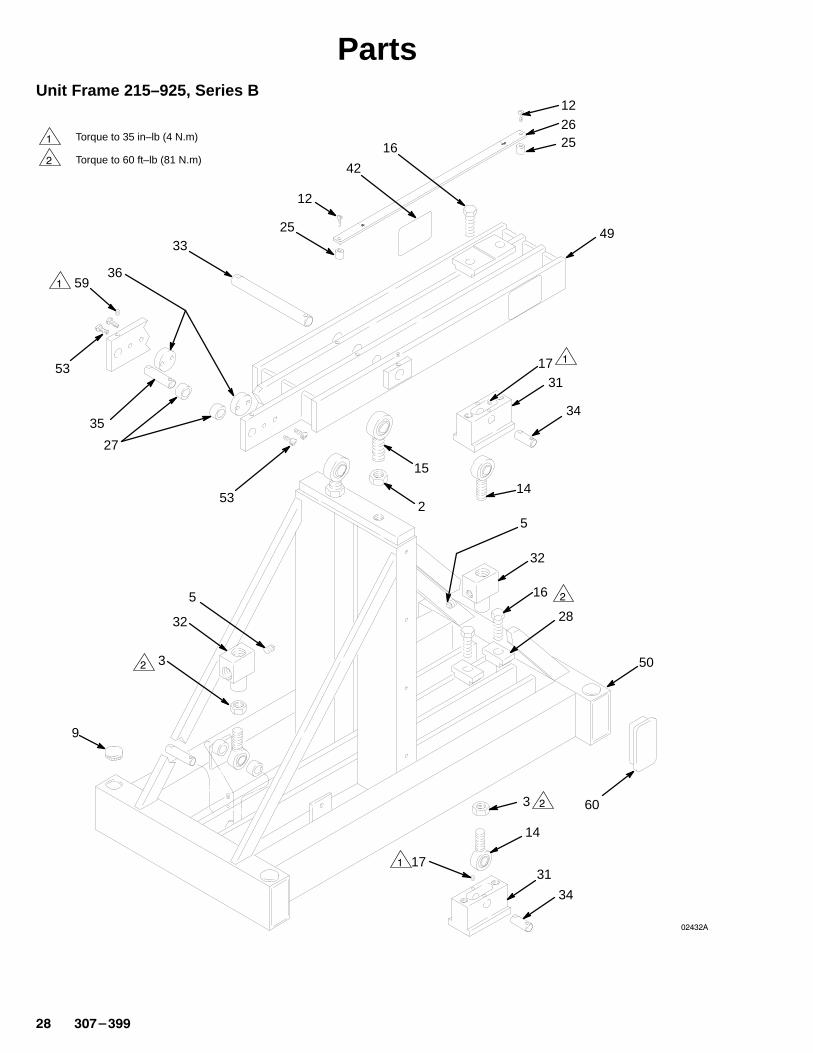
PartsUnit Frame 215–925, Series B
�
�
������
1731
34
14
15
2
16
28
50
3
14
31
34
17
9
3
32
5
53
27
35
3659
53
3325
12
2526
12
42
49
Torque to 35 in–lb (4 N.m)
Torque to 60 ft–lb (81 N.m)
�
�
�
�
�
�
16
32
5
60

������� ��
PartsUnit Frame 215–925, Series BAdditional parts for the Unit Frame are given on pages 30 and 32.
Ref.No. Part No. Description Qty.
Ref.No. Part No. Description Qty.
2 100–071 LOCKNUT, hex, 3/4–16 23 100–155 NUT, 5/8–18 25 100–509 PLUG, pipe, 1/4 npt 39 101–747 PLUG, bottom, 1/4 npt(m) 412 103–836 SCREW, slotted head,
10–32 x 3/4 in. (19 mm) 1214 105–751 BEARING, rod end 315 105–752 BEARING, rod end 216 100–060 CAPSCREW, hex head,
1/2–13 x 1–3/4 inch (44 mm) 417 105–762 SETSCREW, 10–32 825 159–463 SPACER 426 177–042 GAUGE, designation 227 177–086 SPACER, 1/4, nylon 428 177–089 CLAMP, lower 230 177–099 CLAMP, top, index 131 177–100 SUPPORT, pivot pin 2
32 177–101 MANIFOLD, inlet 233 177–105 PIN, pivot, frame 134 177–106 PIN, pivot, housing 235 177–107 PIN, pivot, pump 236 177–108 PLATE, wear 242� 177–144 LABEL, WARNING 444 206–994 THROAT SEAL LIQUID
(not shown) 8 ounces49 215–664 ARM, lever 150 215–665 FRAME BASE, VRHC 152 061–135 HOSE, nylon (not shown) 1.5 feet53 102–790 SCREW, 10–24 459 108–038 SETSCREW, 10–32 260 189–559 CAP, end 4
� Replacement Danger and Warning labels, tags andcards are available at no cost.

���������
Parts
������
21
Ref. 60
61
39
29
4860
637
13
7
84522
47
24
19
4
38
42
40
11
1
51
1258
5557
56
Unit Frame 215–925, Series B

������� ��
PartsUnit Frame 215–925, Series BAdditional parts for the Unit Frame are given on pages 28 and 29.
Ref.No. Part No. Description Qty.
Ref.No. Part No. Description Qty.
1 108–036 STUD, fastener 124 100–377 SCREW, slotted head,
1/4–20 x 5/8 in. (16 mm) 26 100–737 PLUG, pipe, 1/2 npt 47 100–840 ELBOW, street, 1/4 npt (m x f) 18 100–960 GAUGE, air pressure, 0–200 psi
(0–14 bar) 111 108–037 NUT, sheet spring, 10–24 1212 103–836 SCREW, slotted head,
10–32 x 3/4 in. (19 mm) 1213 104–267 AIR REGULATOR, 1/2 npt(f) inlet
and outlet, 1/4 npt(f) gauge ports0–125 psi (0–8 bar) range.See manual 307–204 1
19 155–470 SWIVEL UNION, 90�, 1/2 npt(m)x 1/2 npsm(f) swivel 1
21 157–785 SWIVEL UNION, straight, 3/4 npt(m) x 1/2 npsm(f) swivel 2
22 100–081 BUSHING, 3/8 npt(f) x 1/2 npt(m) 123 158–244 GROMMET 124 158–491 NIPPLE, 1/2 npt 129� 177–096 LABEL, WARNING 137 177–117 MANIFOLD, air 138 177–118 PANEL, safety 1
39 177–119 PANEL, safety 140 177–120 PANEL, safety 142� 177–144 LABEL, WARNING 445 107–142 AIR VALVE, bleed–type master 147 214–652 HOSE, buna–s, 1/2 inch (13 mm)
ID, coupled 3/8 npt(mbe),1.5 foot (0.45 m) long 1
48 215–247 HOSE, nylon, 1/4 inch (6 mm) ID,coupled 3/8 npt (mbe); 5 foot(1.8 m) long 1
51 062–035 MOLDING, rubber 1.8 feet55 180–673 BRACKET 156 100–179 NUT, 10–24 257 100–718 WASHER, no. 10 258 180–674 U–BOLT, 10–24 160 223–778 HOSE, PTFE�, 1/4 inch (6 mm)
ID, coupled 1/4 npsm(fbe),5 feet (1.8 m) long 1
61 164–672 ADAPTER, 3/8 npt x 1/4 npsm(mbe) 1
� Replacement Danger and Warning labels, tags andcards are available at no cost.

���������
AccessoriesUse Only Genuine Graco Parts and Accessories
Inlet Fluid Filter 202–271300 psi (21 bar) Maximum Working PressureFilters foreign particles from fluid. 3/8 npt(f) inlet and3/8 npt(m) outlet. Includes 156–967, 60 mesh screen.
Replacement Screens157–332 40 mesh156–967 60 mesh156–939 100 mesh
Y–Line Filter 101–078500 psi (34 bar) Maximum Working Pressure3/4 npt(f) inlet and outlet. 20 mesh screen included.
Fluid Pressure Regulators250 psi (17.5 bar) Maximum Working PressureFor positive accurate control of the fluid pressure toone spray gun, spray gun or atomizing head.
Regulator No. Regulated Fluid Pressure Range
203–831204–501205–425214–895
0–60 psi (0–4 bar)20–160 psi (1.4–11 bar)0–60 psi (0–4 bar)0–60psi (0–4 bar)
HeaterUsed to control paint viscosity in a heated spray sys-tem.
Model No. Voltage Ports
226–816226–819
120 volt, 60 hz240 volt, 60 hz
1/2 npt(f)1/2 npt(f)
Air Line Lubricator 214–848250 psi (17.5 bar) Maximum Working Pressure1/2 npt inlet and outlet
Air Line Filter 106–149250 psi (17.5 bar) Maximum Working Pressure1/2 npt inlet and outlet
Additional Pump Installation Kit215–934This kit is designed for the addition of another dis-placement pump to the Hydra–Cat.
Color Change ManifoldsFor quick color fluid changes and solvent flush for thedisplacement pumps. 1/4 npt ports
955–395 Two color valve, 1 solvent valve955–396 Three color valve, 1 solvent valve955–397 Four color valve, 1 solvent valve955–398 Five color valve, 1 solvent valve
Air Spray Guns (Aluminum or Stainless Steel)100 psi (7 bar) Maximum Working Pressure1/4 npsm(m) air inlet, 3/8 npsm(m) fluid inlet
AluminumModel No.
Stainless SteelModel No.
Orifice Size
217–900217–901217–902
217–910217–911217–912
0.042 inch0.055 inch0.070 inch
Swivel Caster 102–399Order 4 casters. Mount in sockets provided in a frame.

������� ��
AccessoriesUse Only Genuine Graco Parts and Accessories
Pressure PotsSupplies solvents and fluids at a constant pressure up to 100 psi (7 bar). See manual 307–232.
Model No. Air Outlet Net Weight Description
210–391210–394210–397
3/8 npt(m)3/8 npt(m)3/8 npt(m)
75 lb (34 kg)86 lb (39 kg)
100 lb (45.5 kg)
5 gallon, single regulator without agitator10 gallon, single regulator without agitator15 gallon, single regulator without agitator
210–392210–395210–398
3/8 npt(m)3/8 npt(m)3/8 npt(m)
78 lb (35.4 kg)89 lb (40.4 kg)
105 lb (47.6 kg)
5 gallon, single regulator with agitator10 gallon, single regulator with agitator15 gallon, single regulator with agitator
210–393210–396210–399
1/4 npt(m)1/4 npt(m)1/4 npt(m)
80 lb (36.7 kg)91 lb (41.3 kg)
107 lb (48.5 kg)
5 gallon, dual regulator with agitator10 gallon, dual regulator with agitator15 gallon, dual regulator with agitator
Static MixersA static mixer consists of a tube with helical interior elements which thoroughly blend the base and catalyst into theproper mix.
Part No. Size Wetted Parts Max. Working Pressure Fittings
504–068 8 inch (203 mm) long3/8 inch (9 mm) OD1/4 inch (6 mm) ID24 elements
Polyethylene,Brass
135 psi (10 bar) 1/4 npt(m)
500–639 14 inch (356 mm) long3/8 inch (9 mm) OD.32 inch (8.1 mm) ID27 elements
Stainless Steel 3000 psi (210 bar) Note 1
500–586 25 feet (635 mm) long1/12 inch (12 mm) OD.44 inch (11.2 mm) ID32 elements
Stainless Steel 3000 psi (210 bar) Note 2
NOTE 1: Order tube fittings separately. 502–170, 3/8 inch (9 mm) OD tube x 3/8 npt(m).
NOTE 2: Order tube fittings separately. 502–172, 1/2 inch (12 mm) OD tube x 1/2 npt(m).

���������
Dimensions(A) Height 45.5 inch (1028 mm). . . . . . . . . . . . . . . . . . . . (B) Length 35.0 inch (889 mm). . . . . . . . . . . . . . . . . . . . . (C) Width 18 inch (457 mm). . . . . . . . . . . . . . . . . . . . . . . . (D) Air Inlet* 1/2 npt(f). . . . . . . . . . . . . . . . . . . . . . . . . . . . (E) Fluid Inlets** Two, 3/4 npsm(f) swivel. . . . . . . . . . . . . (F) Solvent Inlet 1/4 npt(m). . . . . . . . . . . . . . . . . . . . . . . . (G) Fluid Outlet 1/4 npt(f). . . . . . . . . . . . . . . . . . . . . . . . . (H) Valve Outlets Two, 1/4 npt(m). . . . . . . . . . . . . . . . . . . Net Weight 267 pound (121 kg). . . . . . . . . . . . . . . . . . . .
*The air manifold has four 1/2 npt(f) plugged outlets.**The fluid manifolds have one 1/4 npt(f) pluggedcleanout port.
������
B
C
A
E
DF
GH
E
Four socketsfor casters.
Air ConsumptionAt 40 psi(2.8 bar)
CFM(m3/min)
At 70 psi(4.9 bar)
CFM(m3/min)
At 100 psi(7 bar)CFM
(m3/min)
At cyclesper
minute
2 (0.06)3 (0.08
3 (0.08)5 (0.14)
4 (0.11)6 (0.16)
1020
4 (0.10)5 (0.14)
6 (0.16)8 (0.23)
8 (0.23)10 (0.28)
3040
6 (0.16)7 (0.19)
10 (0.28)12 (0.34)
13 (0.37)16 (0.45)
5060
8 (0.23) 13 (0.37) 18 (0.51) 70

������� ��
Technical DataAir motor effective diameter 3 inch (76 mm). . . . . . . . . . . . . . . . . . . . . . . . . . . . . . . . . . . Air motor stroke 3 inch (76 mm). . . . . . . . . . . . . . . . . . . . . . . . . . . . . . . . . . . . . . . . . . . . . Operating air pressure range 40 to 180 psi (3 to 12 bar). . . . . . . . . . . . . . . . . . . . . . . . Recommended pump speed 40 cycles per minute. . . . . . . . . . . . . . . . . . . . . . . . . . . . . Maximum fluid inlet pressure 50 psi (3.4 bar). . . . . . . . . . . . . . . . . . . . . . . . . . . . . . . . . Maximum pump operating temperature 180�F (82�C). . . . . . . . . . . . . . . . . . . . . . . . . . Wetted parts:
Model 226–930Primary and secondary displacement pumps Chrome–plated. . . . . . . . . . . . . . .
and Electro–polished stainless steel, Stainless steel, Polyethylene and PTFE plastics �
Models 226–931, 226–932Secondary displacement pumps Chrome–plated steel,. . . . . . . . . . . . . . . . . . . .
nitralloy steel, Stainless steel Tungsten carbide, Zinc–plated steel, PTFE plastic �
All ModelsFluid manifolds Zinc–plated steel. . . . . . . . . . . . . . . . . . . . . . . . . . . . . . . . . . . . . . . . Fluid hoses Nylon, Zinc–plated steel couplings. . . . . . . . . . . . . . . . . . . . . . . . . . . . Pressure relief valves 304 Stainless steel, Graphite-filled PTFE �. . . . . . . . . . .
Tungsten carbide (Nickel binder)Mixer manifold Chrome alloy Nickel Chrome–plated. . . . . . . . . . . . . . . . . . . . . . . .
and zinc–plated steels, Stainless steel, Delrin�, Nylon and PTFE plastics �
Noise level at 100 psi (7 bar) inlet air and at 60 cpm normal load
Pressure level 85 dB(A). . . . . . . . . . . . . . . . . . . . . . . . . . . . . . . . . . . . . . . . . . . . . . . . Power level 96.5 dB(A). . . . . . . . . . . . . . . . . . . . . . . . . . . . . . . . . . . . . . . . . . . . . . . .
Noise level at 180 psi (12.4 bar) inlet air and at 25 cpm maximum load
Pressure level 96.5 dB(A). . . . . . . . . . . . . . . . . . . . . . . . . . . . . . . . . . . . . . . . . . . . . . Power level 111.2 dB(A). . . . . . . . . . . . . . . . . . . . . . . . . . . . . . . . . . . . . . . . . . . . . . . .
Delrin�� is a registered trademark of the DuPont Company.
Loctite� is a registered trademark of the Loctite Corporation.

���������
The Graco Warranty and DisclaimersWARRANTY
Graco warrants all equipment manufactured by it and bearing its name to be free from defects in material and workmanship onthe date of sale by an authorized Graco distributor to the original purchaser for use. As purchaser’s sole remedy for breach of thiswarranty, Graco will, for a period of twelve months from the date of sale, repair or replace any part of the equipment proven defec-tive. This warranty applies only when the equipment is installed, operated and maintained in accordance with Graco’s written rec-ommendations.
This warranty does not cover, and Graco shall not be liable for, any malfunction, damage or wear caused by faulty installation,misapplication, abrasion, corrosion, inadequate or improper maintenance, negligence, accident, tampering, or substitution ofnon–Graco component parts. Nor shall Graco be liable for malfunction, damage or wear caused by the incompatibility with Gracoequipment of structures, accessories, equipment or materials not supplied by Graco, or the improper design, manufacture, instal-lation, operation or maintenance of structures, accessories, equipment or materials not supplied by Graco.
This warranty is conditioned upon the prepaid return of the equipment claimed to be defective to an authorized Graco distributorfor verification of the claim. If the claimed defect is verified, Graco will repair or replace free of charge any defective parts. Theequipment will be returned to the original purchaser transportation prepaid. If inspection of the equipment does not disclose anydefect in material or workmanship, repairs will be made at a reasonable charge, which charges may include the costs of parts,labor and transportation.
DISCLAIMERS AND LIMITATIONS
The terms of this warranty constitute purchaser’s sole and exclusive remedy and are in lieu of any other warranties (express orimplied), including warranty of merchantability or warranty of fitness for a particular purpose , and of any non–contractualliabilities, including product liabilities, based on negligence or strict liability. Every form of liability for direct, special or consequen-tial damages or loss is expressly excluded and denied. In no case shall Graco’s liability exceed the amount of the purchase price.Any action for breach of warranty must be brought within two (2) years of the date of sale.
EQUIPMENT NOT COVERED BY GRACO WARRANTY
Graco makes no warranty, and disclaims all implied warranties of merchantability and fitness for a particular purpose , withrespect to accessories, equipment, materials, or components sold but not manufactured by Graco. These items sold, but notmanufactured by Graco (such as electric motor, switches, hose, etc.) are subject to the warranty, if any, of their manufacturer.Graco will provide purchaser with reasonable assistance in making any claim for breach of these warranties.
Graco Phone NumbersTO PLACE AN ORDER , contact your Graco distrib-utor, or call this number to identify the distributorclosest to you: 1–800–367–4023 Toll Free
FOR TECHNICAL ASSISTANCE, service repairinformation or assistance regarding the application ofGraco equipment: 1–800–543–0339 Toll Free
Sales Offices: Atlanta, Chicago, Detroit, Los AngelesForeign Offices: Belgium; Canada; England; Korea; Switzerland; France; Germany; Hong Kong; Japan
GRACO INC. P.O. BOX 1441 MINNEAPOLIS, MN 55440–1441PRINTED IN U.S.A. 307–399 September, 1980, Revised August 1995