Embed Size (px)
Citation preview

10 MPa double-acting type hydraulic cylinder
100H-2 SERIES
New floating cushion provides effective cushioning and quick start of each stroke.10 MPa double acting hydraulic cylinders with bores from 32 mm to 125 mmSeals in sliding sections conform to ISO standards for packing groove
Lightweight and compact body realized by conformity to ISO 10762/JIS B8367-5 standard.
CAT. -524aA 11

22
M20×1.5
M16×1.5
30 141+100=241
105+100=205
100H-2
70H-8
30
25
Designed to ISO 10762New floating cushion
High-performance cushionVarious models
Switches set
10 MPa double-acting type hydrau lic cylinder with bores from 32 mm to 125 mm100H-2 SERIESConformance to both ISO and JIS standards is enhanced, with the spread of global standards for hydraulic cylinders.
100H-2 Series cylinders conform to ISO 10762 (JIS B8367-5).100H-2 Series cylinders conform to ISO 10762 (JIS B8367-5).
Designed to ISO10762 (JIS B8367-5)
New floating cushion provides effective cushioning and
quick start of each stroke.
Switches can be used to all bore sizes in standard, 32 mm
to 125 mm.
Seals in sliding sections were designed to ISO standard.
Various models
7 types of bores from 32 mm to 125 mm, 10 types of mounting styles
Double-rod type is also available
Rod B series
Piping ports are applicable to Rc (tapered thread) and G (BSPP)
Cylinders with boots or rod end attachment are available
Succeeded features of 140H-8 and 160H-1 Series
High-performance cushion
Cushion valve easy to adjust
Small switches AX and AZ, with great variety and improved
maintainability
Features
Cushion plunged Startup
Cover
Cushion ring
Float ring
Set ring
Oil
Piston rod
With 63 mm bore, 500 kg load
Theoretical outputs when 10 MPa pressure is applied to 100H-2 and 7 MPa is applied to 70H-8
Output: Increased by 14%
4. Output
3. Improved start performance by new floating cushion
Start performance of cylinder
Cyl
inde
r sp
eed
Start
0.1 0.2 Sec
70H-8
100H-2
400mm/s
Time
Comparison to 70H-8 SeriesComparison to 70H-8 Series 1. Compact body
465
SD type with 40 mm bore and 100 mm stroke
SD type with 100 mm bore and 100 mm stroke
Mounting length: Reduced by 16%
Weight: Reduced by 42%
2. Weight
17.9kg100H-2
30.8kg70H-8
NEWNEW

100H-23
1. General port G thread typesTwo types of port G threads, flat surface type and corner O-ring seal type, are mainly used for hydraulic cylinders. We adopted the flat surface type as the standard type.
• Flat surface type • Corner O-ring seal type
2. Sealing methods and joint typesFlat surface type• Elastomer joint • Edge seal joint
• O-ring seal joint
Corner O-ring sealing type
Joint shape
Gasket
Joint shape
O-ring Backup washerMetal ring
Joint shape
Backup washer O-ringO-ring
Joint shape
Flat spot facing and sealing on spot facing face Tapering to fit O-ring and sealing with O-ring
The O-ring is fitted to the tapered section for sealing. As for another type, the backup washer is fitted onto the O-ring, and tightened with the lock nut in order to change the angle of the joint.
3. standard G thread sizesAll the joints for flat surfaces are usable.
FF port dia DE AE
G1/8
G1/4
G3/8
G1/2
G3/4
G1
17.2
21.5
25.5
30
36.9
46.1
8
12
12
14
16
18
Unit : mm
4. Applicable series and port sizes
Seriesφ20 φ25 φ32 φ40 φ50 φ63 φ80 φ100 φ125 φ140 φ150 φ160
100H-2-
-
-
- G1/4 G3/8 G3/8 G1/2 G1/2 G3/4 G3/4
-
-
-
-
-
-
Bore (mm)
Unit : mm
Note) • Spacers for the rod side ports are provided for the 100H-2 with 32 mm bore. Be sure to use them for piping.
DE
FF
AE
Sealing with using the gasket for the joint to be sealed on the end face.
Sealing by tightening force with the metal surfaces come into contact with each other.
Sealing with using the O-ring. The metal ring is fitted to the O-ring on the outside. As for another type, the backup washer is fitted onto the O-ring, and tightened with the lock nut in order to change the angle of the joint.
Port G thread type

10 MPa double-actinghydraulic cylinder 100H-2 SERIES
For safety use
Selection materials
Precautions for use (Be sure to read them)
100H-2
How to order 100H-2
Dimensional drawing of 100H-2
Switch specifications
List of seals
.........................................................5
................................................7
......17
...................................................................21
..........................................23
........................29
...........................................58
..........................................................88

100H-2 For safety use5
Inappropriate handling of the products may lead to the unreliable performance or serious accidents. In order to prevent any accident, be sure to read carefully this catalogue, and fully understand the contents for safe handling.
Remember that your special attention must be paid to the messages with the words "DANGER", "WARNING", "CAUTION", and "NOTES". Non-observance of these messages may pose dangers to operators or machines. These are important safety messages and require your strict observance, adding to ISO4413, JIS B 8361 and other safety rules.
Operators with sufficient knowledge and experiences should operate the equipment.The assembly, operation, and maintenance of machines and devices using hydraulic equipment must be performed by only the persons with sufficient knowledge and experiences.Keep away from fire.Since highly ignitable working oil is used for hydraulic equipment, the possibility of fires is inevitable.Do not handle the machines and devices or remove the hydraulic cylinder until safety is confirmed.
Prior to removal of hydraulic cylinders, ensure that safety countermeasures are provided, the hydraulic power supply is stopped, and the pressure in the hydraulic circuit is lost.Ensure the safety of prevention against the drop of matters to be driven before maintenance and service of machines and devices.The temperature of a cylinder is very high right after operation is stopped. Ensure that the temperature of the cylinder and oil is low before removing the cylinder.When restarting the machines and devices, ensure that there is no abnormality in the bolts and other components, and slowly increase the pressure of the hydraulic source from low pressure to the set pressure.
Mount protect covers if any danger may occur to operator’s body.If there is any danger to operator’s body by matters to be driven or the movable part of the cylinder, try to consider the structure so that any part of operator’s body cannot touch them.Deceleration circuit or shock absorber may be required.When the speed of matters to be driven is excessively high, or the weight of them is excessively heavy, shock absorption by only the cylinder cushion may be difficult. In such a case, the provision of the deceleration circuit in front of the cushion or the external shock absorber is required as countermeasures against shocks. Also, take the hardness of machines and devices into consideration.Securely connect so that the fixed part and connecting part of the cylinder will not be loosened.
Use the bolts with the specified size and strength class for fixing the cylinder attachments, and clamp them with the specified clamping
torque. For rotary attachments, use the pin of the specified size.If the connection is inappropriate or the bolts or the pin with the size other than the specified may lead to the slackened or damaged bolts due to the driving force and reaction force of the cylinder.Use mounting components made of the material with sufficient hardness.
Do not loosen the air vent valve excessively during air vent. Excessive loosening of the air vent valve may lead to coming-off or jumping of the air vent valve from the cylinder, causing spouted oil, leading to injury or malfunction of the cylinder.Consider the movements at an emergency stop.Consider the design without a risk of injuries of the operator or damages on machines and devices due to the cylinder movement, preparing for the case that the safety device is actuated to stop the machines at the emergency stop or system abnormalities due to power suspension.Check the specifications.
The products in this catalogue have been designed and manufactured as general industrial machine components. DO NOT use them under the pressure, temperature, or operating environment out of the specified range. Otherwise, the breakage or malfunctions of the machines may occur.For electric components, such as switches, carefully check the specifications, including those of load current, temperature, and shocks. Otherwise, malfunction, breakage, or inflammable damages may occur.
DO NOT make any modification on the products.Otherwise, injury, electric shocks, fires due to malfunctions may occur.Take safety countermeasures into consideration, and contact us before using the products under the conditions and environment shown below.
The use of the products under the environment or conditions other than specified and the use of them outdoors.Applications related to public safety (Ex.: machines or devices used for atomic, railway, aeronautics, car, medical, and entertainment industries, emergency shutdown circuit, brake circuit, and machines and devices which contact drinks and foods)Use in safety equipment.Applications requiring reliable safety.
The instructions in this catalogue are classified into "DANGER", "WARNING", "CAUTION", and "NOTES", according to the degree of risk and hindrance.
Related laws and rules
• High-pressure gas preservation law• Labor safety and hygiene law• Fire laws• ISO 4413 : Hydraulic fluid power-General rules for the application of equipment to transmission and control systems• ISO 7425-1 : Hydraulic fluid power-Housings for elastomer-energized, plastic-faced seals-Dimensions and tolerances-
(applicable to the piston packings for 160H-1 Series)• ISO 5597 : Hydraulic fluid power-Cylinders-Housings for piston and rod seals in reciprocating applications-
Dimensions and tolerances- (applicable to the piston packings (U-packings) and rod packings for 160H-1 Series)• ISO 6195 : Fluid power systems and components-Cylinders-Housing for rod wiper rings in reciprocating applications-
Dimensions and tolerances (applicable to the wiper rings for 160H-1 Series)• JIS B 8361 : General rules for hydraulic system• JIS B 8367-5 : Hydraulic cylinder• JIS B 8243 : Structure of pressure container• NAS 1638 : Classification of contamination particles levels
Instructions in this catalogue
Instructions which are required to be followed for appropriate use of the products.
Potential hazardous situation. Unless the situation is avoided, slight or medium injury, or physical damages may occur.
Potential hazardous situation. Unless the situation is avoided, loss of life or serious injury may occur.
Imminent hazardous situation. Unless the situation is avoided, loss of life or serious injury may occur.DANGER
WARNINGCAUTIONNOTES
These products have been designed and manufactured as a general industrial machine component.
Warning
If you have any question, contact us.

100H-2For safety use6
(General precautions)When the weight of the cylinder exceeds 15 kg, use a lifting tool or a carrier.Keep good arrangement and cleanliness of the working site. The slippage due to oil leak may lead to a turnover. Keep clean, and try to find oil leak soon.When mounting a cylinder, be sure to perform centering. Otherwise, the rod and tube may be disordered, causing the wear and breakage of the tube inside, surfaces of bush or rod, and packings. The rod may not move smoothly, causing stick slip or noise.When using the external guide, adjust it so that it is not disordered in any position of the stroke, or connect considering the connection of the rod end and loads.Use the working oil applicable to the material of the packings for the cylinder, and DO NOT mix working oil of other types.The recommended cleanliness of working oil is the grade NAS 12 or higher.
(Piping)Perform flushing before piping to reduce chips, cutting oil, dusts in the pipes.Remove the cylinder before flushing to avoid the ingress of flushing fluid into the cylinder.Application of sealing tapeWhen connecting pipings with sealing tape, apply the tape with one or two threads on the thread tip left.When screwing pipings and fittings in, take care to avoid the ingress of chips or sealing material of the piping screw into the piping. When applying liquid packing to the fittings, similarly pay attention. Scraps of sealing tape or chips may cause oil leak or other malfunctions.When piping, take care to avoid air accumulation.When using steel pipe for piping, select proper size and avoid rusts and corrosion.If welding is required for piping, ground in other safety location to avoid ground current in the cylinder. The ground current between the bush and rod, cylinder tube and piston may lead to a spark, causing the damages on surfaces and malfunctions.
(Adjustment of air vent and cushion)Excessive loosening of the air vent valve during air vent may lead to coming-off or jumping of the air vent valve from the cylinder, causing spouted oil.
Feed oil under a low pressure (such that the cylinder can move at a low speed of approximately 10 mm/s), and loosen the air vent valve by one or two turns (counterclockwise) to vent air in the oil from the air vent valve.For cylinders without air vent valves, install throttle valves to vent air.
The initial increase of the piston speed during the cushion adjustment may lead to abnormal surge pressures, causing the damaged cylinder or machines.
Slowly increase the piston speed from the low speed of approx. 50 mm/s or lower to adjust the cushion.When adjusting the cushion, adjust depending on matters to be driven (loads).If the cushioning is excessive, the cylinder may not reach the stroke end due to the contained oil in the cushion.
(Notes on trial run and operation)Ensure that the machines and devices are correctly mounted. DO NOT start without the confirmation of no oil leak.Run with the minimum pressure to start the piston rod (the piston speed must be approx. 50 mm/s or lower), and ensure that it is worked smoothly.
(Maintenance and service)Perform maintenance and service (daily and regular inspection) to use cylinders safely for a long period.
Prior to the maintenance and service, be sure to shut down the pressure source. Completely relieve the pressure in a cylinder.When relieving the pressure in a cylinder after shutting down the pressure source, the rod may be actuated with a load. Pay attention to the unexpected movement, and try to provide reliable safety countermeasures against it.
(Storage)DO NOT pile up cylinders. If any vibration is applied to the piled cylinders, they may become unfastened, causing an extreme danger and the damaged parts.DO NOT apply a vibration nor a shock to the stored cylinders, causing the damaged parts.Provide rust preventive measures to avoid rust occurrence to the stored cylinders.
(Wiring and connection)Prior to wiring, be sure to shut down the power supply to the electric circuit of the connection side.Otherwise, the operator may get an electric shock during working, or the switches or load devices may be damaged.Pay attention to avoid bending, pulling, twist of the switch cord, causing broken wires.Especially, provide appropriate measures to avoid any load applied to the end of the switch cord, including the fixing of the switch cord. When fixing the cord, do not clamp the cord excessively. Otherwise, the cord may be damaged, causing broken wires (of the cord).Any load applied to the end of the cord may lead to the damaged electric circuit boards in the switches.The larger bending radius is better. If it is excessively small, the cord may be damaged. The recommended bending radius is twice of the cord dia. or larger.
(Wiring)If the connection distance is long, fix the cord every 20 cm to avoid a sag in the cord.When laying the cord on the floor, protect it by covering with metallic tubes to avoid direct treading on it or a crush under machines. Otherwise, the coating of the cord may be damaged, leading to the broken wires or short-circuit.The distance between the switches and load devices or power supply must be 10 m or shorter.Otherwise, inrush current may occur to the switches during operation, causing the damaged switches.DO NOT bind the cord with high-voltage cables for other electric appliances, the power supply, nor with the power supply cord. NEVER perform wiring near these cables.Otherwise, noises may enter the switch cord from the high-voltage cables and power source or power supply cable, causing the malfunctioned switches or load devices. It is recommended that the cord is protected with a shield tube.
(Connection)DO NOT directly connect the switches to the power supply. Be sure to connect them with the specified load devices, such as small relays and programmable controllers. Otherwise, short-circuit may occur, causing the inflammable damage of the switches.Carefully check the switches used, voltage of power supply and load devices, and current specifications.Inappropriate voltage or current specifications may lead to the malfunctioned or damaged switches.Perform wiring correctly according to the colors of lead wires. Prior to wiring, be sure to shut down the power supply to the electric circuit of the connection side.Operation, wrong wiring, and short-circuit of load devices with electric current supplied may lead to the damaged switches and electric circuit in the load devices. Even if the short-circuit is momentary, it causes the inflammable damage of the main circuit or output circuit.
Caution

100H-2 Selection materials7
φ32
φ40
φ50
φ63
φ80
φ100
φ125
Boremm
804
1257
1963
3117
5027
7854
12272
Set pressure MPaPressurized area mm2
Theoretical output table at out stroke (load rate 100%) Unit : kN (1kN 102kgf)
Unit : kN (1kN 102kgf)
φ32
φ40
φ50
φ63
φ80
φ100
φ125
Theoretical output table at retract stroke (load rate 100%)
14.0
7.70
12.27
18.87
29.39
48.11
75.47
117.93
10.0
5.50
8.77
13.48
20.99
34.36
53.91
84.23
7.0
3.85
6.14
9.43
14.70
24.05
37.74
58.96
5.0
2.75
4.38
6.74
10.50
17.18
26.95
42.12
3.5
1.92
3.07
4.72
7.35
12.03
18.87
29.48
1.0
0.55
0.88
1.35
2.10
3.44
5.39
8.42
550
877
1348
2099
3436
5391
8423
Series type Boremm
Rod dia.mm
Pressurized area mm2
Set pressure MPa
The bore of a hydraulic cylinder depends on the required cylinder force.
Push side cylinder forceF1 = A1 × P × β (N)
F2 = A2 × P × β (N)
Pull side cylinder force
Supply
W d
A2
D A1
F1
F2
A1 : Out stroke piston pressurized area (mm2) A1 = D2
A2 : Retract stroke piston pressurized area (mm2) A2 = (D2 — d2)
D : cylinder bore (mm) d: piston rod dia. (mm)
P : set pressure (MPa)
β : load rate
The hydraulic cylinder theoretical output table is based on the calculation results of the formula above.
Selection of cylinder bore
14.0
11.26
17.59
27.49
43.64
70.37
109.96
171.81
10.0
8.04
12.57
19.63
31.17
50.27
78.54
122.72
7.0
5.63
8.80
13.74
21.82
35.19
54.98
85.90
5.0
4.02
6.28
9.82
15.59
25.13
39.27
61.36
3.5
2.81
4.40
6.87
10.91
17.59
27.49
42.95
1.0
0.80
1.26
1.96
3.12
5.03
7.85
12.27
16.0
12.86
20.11
31.40
49.88
80.42
125.66
196.35
16.0
8.80
14.02
21.56
33.59
54.98
86.26
134.77
φ18
φ22
φ28
φ36
φ45
φ56
φ70
100H-2
When deciding the actual cylinder output, the resistance in the cylinder slipping part and the pressure loss in piping and machines must be considered.The load rate is the ratio of the actual force loaded onto the cylinder to the theoretical force (theoretical cylinder force) calculated from the circuit set pressure. The general set points are shown below.
For low speed working ..... 60 to 80%For high speed working ..... 25 to 35%
π4
π4
Notes) • When deciding the actual cylinder output, consider the resistance in the cylinder slipping part and the pressure loss in piping and machines.
• Remember that the output at start may be decreased when the piston comes to a close contact status at the stroke end due to a load.

100H-2Selection materials 8
M
M
Notes on piston rod buckling
• Definition of a load when the cylinder stopping method is selected
• Definition of a load when the cylinder stopping method is selected
M
M
Calculation of cylinder buckling Calculation method of cylinder buckling (use of buckling chart)
L
L
3kN
Load
2258
φ50 (Rod B type)
Rod dia (φ28)
mm
Cylinder bore
Series name
100H-2
φ32
φ18 φ22 φ28 φ36 φ45 φ56 φ70
φ40 φ50 φ63 φ80 φ100 φ125
Rod diameter list Unit: mm
In the case of 1
In the case of 2
1
2
In the case of : load = M • gIn the case of : load = µ M • g µ : frictional coefficient g : gravity acceleration
9.8 m/s2
M : load weight (kg)
1) Be sure to calculate the cylinder buckling.
2) In the case of using a hydraulic cylinder, the stress and buckling must be considered depending on the cylinder stroke.The strength in the case that the piston rod is regarded as a long column, the buckling strength, cannot be enhanced by adopting highly tension-proof steel or heat treatment. The only way to improve the buckling strength of a cylinder is to widen the piston rod dia., and therefore, the selection of the piston rod is the very important point.The buckling chart shown in the next page, based on the Euler’s equation that is applicable to an upright long column, indicates the maximum safe L values against the piston rod dia. when the cylinder is used with the compressive load that is most frequently applied.
3) When buckling occurs to a cylinder, the cylinder rod may be bent, causing malfunctions or serious accidents.
1. Find the L value (distance between the cylinder mounting position and load mounting position) with a cylinder fully extended.
2. Select any buckling chart depending on the mounting style, and find the maximum working load.
< Exercise >Find the maximum working load for the 100H-2, φ50, rod B (rod dia. φ28), in case that the stroke is 1000 mm, CA type with the rod end eye.
< Answer >1. Find the L value with the cylinder fully extended. From the dimensional drawings in this catalogue,
the L value can be calculated by the formula below. L = 158 + 67+ 1000 + 1000 = 2225 mm2. From the buckling chart of the both ends pin joints,
the load can be found as below. W = 3 kN ( 306 kgf)
Prior to the calculation of the piston rod buckling, consider the cylinder stopping method. The stopping methods of a cylinder include the cylinder stopping method, in which a cylinder is stopped at the stroke end, and the external stopping method, in which a cylinder is stopped with the external stopper. The definition of load differs depending on the selection of the stopping method as shown below.
The state of stopping at the cylinder stroke end as shown in the figure.For the load required for the buckling calculation, apply the formula below.
The state of halfway stopping with the external stopper as shown in the figure.The load required for the buckling calculation in this case is not the M, but the cylinder theoretical output (Relief set pressure MPa × Piston area mm2).

100H-29
L L
L
L
Buckling chart by cylinder mounting style
Fixed cylinder, rod end free
1 2 3 4 5 10 20 30 40 50 100
L (×100mm)
1
500
100
50
10
5
0.5
0.1
1000
Load
(kN
)
Rod dia φ45
Rod dia φ56
Rod dia φ70
Rod dia φ36R
od dia φ28
Rod dia φ22
Rod dia φ18
1 2 3 4 5 10 20 30 40 50 100
L (×100mm)
1
500
100
50
10
5
0.5
0.1
1000
L
LL
L
Buckling chart by cylinder mounting style
Both ends pin joints
Load
(kN
)
Rod dia φ45
Rod dia φ56
Rod dia φ70
Rod dia φ36
Rod dia φ28
Rod dia φ22
Rod dia φ18
Buckling chart Buckling chart

100H-2 10
L L
L
L
1 2 3 4 5 10 20 30 40 50 100
1
500
100
50
10
5
0.5
0.1
1000
Fixed cylinder, rod end pin joint
1 2 3 4 5 10 20 30 40 50 100
1
500
100
50
10
5
0.5
0.1
1000
L L
L
L
Buckling chart by cylinder mounting style
Fixed cylinder, rod end guide
L (×100mm)
Load
(kN
)
L (×100mm)
Load
(kN
)R
od dia φ45R
od dia φ56
Rod dia φ70
Rod dia φ36
Rod dia φ28
Rod dia φ22
Rod dia φ18
Rod dia φ45
Rod dia φ56
Rod dia φ70
Rod dia φ36
Rod dia φ28
Rod dia φ22
Rod dia φ18
Buckling chart by cylinder mounting style
Buckling chart Buckling chart

100H-2 Selection materials11
Selection of seal material
Adaptability of seal material to working oil and working temperature range of seal material
Nitrile rubber
Urethane rubber
Hydrogenated nitrile rubberr
Petroleum-based fluid
Waterglycol fluid
Phosphate ester fluid
W/Ofluid
O/Wfluid
-50 -10 0 50 80 100 120 150
Seal material
Applicable working oilOil temperature and ambient temperature (°C)
Criteria for selection of urethane rubber and nitrile rubber
Abrasion resistance
Life against inferiority of working oil
Life with high oil temperature
Oil leak from rod
High use frequency under high pressure
Low use frequency under low pressure
Pull strength (reference value) (MPa)
Packing material
Items
Table of seal selection criteria
Nitrile rubber
(JIS B type)
17
Urethane rubber
(JIS A type)
47
Hydrogenated nitrile rubber
(JIS B type)
30
Note) , , and - marks indicate the priority of selection in this order.
Prior to the selection of seal material, check the conditions below.1. Oil temperature in a cylinder and ambient
temperature2. Type of working oil3. Use freguency
Notes) • Select the packing material suitable for the working oil used. The wrong material selection may lead to the inferiority of packing material, causing the damaged packings.
• The recommended cleanliness level of the working oil used is the NAS grade 12 or higher.
• DO NOT mix fluids of different types. Otherwise, the mixed fluids may be changed in quality, posing inferiority of the packings.
• In the case that working oil including water (water-glycol fluid, water in oil fluid, oil in water fluid, etc.) is used, and the cylinder tube is made of carbon steel for machine-structural use, it is recommended to plate the cylinder tube inside. When you request the plated cylinder tube,
Notes) • The and -marked items are applicable, while the -marked items are inapplicable. For the -marked items, contact us.• In case that the priority is given to the abrasion resistance, adopt the packing material of the -marked combinations.• In case that hydrogenated nitrile rubber is adopted for the use of water-glycol fluid, water in oil fluid, oil in water fluid, the oil
temperature must be ranged from -10 to +100°C.• The temperature range in the table above indicates the working temperature range of packing material, and it is not the
working temperature range of the cylinder. For the use of a cylinder at high temperature, contact us.• When using combined seals (code 8), refer to the notes on nitrile rubber.
The material of the packing for standard cylinders includes urethane rubber and nitrile rubber. When selecting the material, refer to the criteria for selection in the table below.• Characteristics of urethane rubber Urethane rubber, having 2.5 times pull strength of nitrile rubber as shown in the table below, features the superior
resistance against pressure and abrasion.However, urethane rubber may be changed in quality due to heat and inferiority in working oil in a long run (and the multiplier effect of oil temperature), and therefore, disassembly and inspection are required every year.
• Characteristics of nitrile rubberThe influences of heat and inferiority in working oil on nitrile rubber is less than those on urethane rubber. Since the pull strength of nitrile rubber is less than that of urethane rubber, nitrile rubber is rather inferior to urethane rubber in the resistance against pressure and abrasion. Therefore, in case that the use frequency is low under low pressures and disassembly and inspection are not performed for two or three years, it is recommended to adopt nitrile rubber.
• Characteristics of hydrogenated nitrile rubberHydrogenated nitrile rubber is most suitable for hot places or places where more reliable abrasion resistance than that of nitrile rubber is required at normal temperature.
Notes)

100H-2Selection materials 12
0.050.1
0.2
0.3
0.5
Oil
leak
(cm
3 )
20 25 40 50 60 80 100 120 140
Rod dia.D (mm)
Nitrile rubber and hydrogenated nitrile rubber
Urethane rubber
Less than 0.05cm3
Less than 0.05cm3
Relation between external oil leak amount and rod dia.
External oil leak is the total of oil leak from the wiper ring with the piston moving distance of 100 m. (Refer to JIS B8367).
Selection of boots
J
JN
JK
Sym
bols
Name
Nylon tarpaulin
Chloroprene
Conex
Resistible tempera-ture
80°C
130°C
200°C
Material
Vinyl-coated nylon cloth
Nylon cloth coated with chloroprene
Silicon-coated Conex cloth
Boots type and resistible temperature
Structures and selection guidance of seals for 100H-2
Urethane rubber
Hydrogenated nitrile rubber
Hydrogenated nitrile rubber
Hydrogenated nitrile rubber
Hydrogenated nitrile rubber
Hydrogenated nitrile rubber
Packing code
Name of type
1
Nitrile rubber type
2
Urethane rubber type
6
Hydrogenated nitrile rubber type
8
Combined seal type
Pac
king
str
uctu
re
Piston packing
Rod packing and wiper ring
Fixed section (including O-ring) Nitrile rubber Nitrile rubber Hydrogenated nitrile rubber Nitrile rubber
WWeight
Notes on packings• If any external force is applied to the cylinder as shown in the figure on the right, and the
piston must be held at the fixed position, use of the nitrile rubber type or hydrogenated nitrile rubber type (code 1 or 6) U-packing as the piston packing is recommended.
• When the cylinder is operated at approximately 20 mm/s, stick-slip (crack) may occur to the nitrile rubber type, urethane rubber type, or hydrogenated nitrile rubber type packing depending on conditions (viscosity of fluid and hardness of machine).Combined seals are suitable for general use. For details, contact us.
Note) 1. If the boots are provided, the length of extended cylinder rod is changed.Note) 2. Remember that the resistible temperatures in the table above are for the
boots, not for the cylinder.Note) 3. Conex is the registered trademark of Teijin Ltd.
If hydraulic cylinders are used in the places under unfavorable conditions, where are subjected to wind, wind and rain, and dusts, the piston rod especially needs to be protected. When selecting the boots, consider the environment conditions and temperature.
Fluoric resin
Nitrile rubber
Urethane rubber
Nitrile rubber
Wear ring Wear ring

100H-2 Selection materials13
V = 1.67 × 10⁴ × Qc/A
Chart of relation between cylinder speed, required flow rate, and flow velocity in pipe
Oil volume required
10 7 5 3 2 1 0 50 70 100 200 300 500
100 /min
200 /min
400 /min
40 /min50 /min
30 /min
20 /min
10 /min
5 /min
25A
15A20A
φ125
φ100
φ40φ32
φ50φ63
φ80
1B (φ25 )3/4 B (φ19.4)1/2B (φ14.3)3/8 B (φ10.9)1/4 B (φ7.8)
Appropriate range
Check of port dia. depending on cylinder speed
V
: cylinder speed (mm/s)Qc : oil volume supplied into cylinder (L/min) A : pressurized area of piston (mm2)
100H-2 Series standard port diameter
Bore (mm)
Port dia. Rc, G
φ32
1 4
φ40
3 8
φ50
3 8
φ63
1 2
φ80
1 2
φ100
3 4
φ125
3 4
Note) Spacers for the rod side ports are provided for the 100H-2 with 32 mm bore. Be sure to use them for piping.
Cylinder speed depends on the volume of oil fed into a cylinder.The cylinder speed V can be obtained from the following formula:
< Example >In the case of the 100H-2 series with an 80 mm cylinder bore and 300 mm/s cylinder speed, is the standard port dia. applicable? Also, find the flow velocity in pipe.
< Answer >In the chart below, find the cross point of the straight line from the point of 300 mm/s cylinder speed and the slant line of 63 mm cylinder bore, and draw a straight line parallel with the lateral axis until it reaches the slant line of the port dia. 1/2 (the standard port dia. for the 100H-2 series with a cylinder bore of 80 mm).From the cross point on the slant port dia. line, draw a straight line parallel with the longitudinal axis until it reaches the lateral axis. From the cross point, the correspondig flow velocity in pipe is 5.2 m/s.Since the cross point found based on the port diameter, cylinder speed, and bore is within the appropriate range, the standard port diameter is applicable.
The chart below shows the relation between the speed and the required flow rate for each size of standard hydraulic cylinders (cylinder inside) and that between the required flow rate and flow velocity in pipe for each port dia.
Note)The appropriate flow velocity in pipe for the appropriate range is 7 m/s or under. In general, if the flow velocity in pipe exceeds 7 m/s, the piping resistance and pressure loss are increased, causing less output during cylinder work and lower speed.To reduce pressure loss, adopt piping with larger dia. of one grade to the cylinder port. The flow velocity is calculated with steel tube for piping S ch80.
Pipe inside flow velocity (m/s) Cylinder speed (mm/s)

100H-2Selection materials 14
Maximum energy absorbed of cylinder cushion
The procedures to find each item above are shown below.
Inertia energy of load at the inrush into cushionE1
Maximum energy absorbed of the cylinder cushionEt
Energy generated by the external force applied to the cylinder at the inrush into cushion
E2
CAUTION
Inertia moment calculation table
D
M
b a
The conditions of absorbed energy allowable for the cylinder cushion can be obtained from the formula below. If a load is moved horizontally and straight, see the simplified charts on the page for selection.
Find the inertia energy of load at the inrush into cushion, E1. In the case of linear movement: E1 = MV2/2 (J) M : load weight (kg) V : load speed at the inrush into cushion (m/s) In the case of rotation movement: E1 = ω2/2 (J) : inertia moment of load (kg • m2) ω : angular velocity of load at the inrush into cushion (rads)Notes: If the cylinder speed is less than 0.08 m/s (80 mm/s), the
cushioning effect is weakened.Even if the cylinder speed is less than 0.08 m/s (80 mm/s), suppose it is 0.08 m/s to find the E1.In the case of rotation movement, even when the cylinder speed is 0.08 m/s or lower, similarly suppose it is 0.08 m/s, and calculate the angular velocity ω to find the E1.
Find the energy generated by the external force applied to the cylinder at the inrush into cushion, E2.
The forces acting in the direction of the cylinder axis at the inrush into cushion are shown below.
• The force applied to the cylinder by the gravity of load• The force applied by other cylinders• The force applied to the cylinder by springs
Find the external force F, which is applied to the cylinder at the inrush into cushion, and the energy E2 by using the "Chart of conversion of external force into energy at the inrush into cushion".In case that such an external force is not applied, the following condition is satisfied: E2 = 0.For the selection of cushion, suppose that the frictional resistance of load is 0.
Find the maximum energy absorbed of the cylinder cushion, Et.Find it with the corresponding chart of the "Maximum energy absorbed".
Ensure that E1 + E2 is same as the maximum energy absorbed Et, or smaller.If the following condition is satisfied, the cylinder is applicable: E1 + E2 Et.
If the following condition is satisfied, the cylinder is inapplicable: E1 + E2 Et.In such a case, perform the steps below, and then, select again.
• Decrease the inertia force of load.• Decrease the external force applied to the cylinder.• Lower the set pressure.• Widen the cylinder bore.• Install a shock absorber.
When installing a shock absorber, refer to the "TAIYO Shock absorber general catalogue".DO NOT use the cylinder cushion together with a shock absorber. Otherwise, the inertia force of load may be applied to either of them due to the difference of cushioning characteristics.
Be sure to use cylinders within the range of the maximum energy absorbed of the cylinder cushion.Otherwise, the cylinder or the peripheral devices may be damaged, leading to serious accidents.
Outline Inertia moment:
In the case of the axis at rod end
In the case of a cylinder (including a disk)
Note) The axis passes through the center of gravity.
1:
In the case of an arm (rotated around the axis A)
=M 2
3
MD2
8
= M1 12+ 1
+ M2 22
3The inertia moment of a weight when the axis passing through the center of the gravity of the weight (axis B) is the center.
M1:M2:
:
:
Weight of a weightWeight of an armDistance from the axis A to the center of a weightArm length
In the case of the axis in the middle of rod
In the case of a rectangular parallelepiped
Note) The axis passes through the center of gravity.
Note) The axis passes through the center of gravity.
( 1)
M (M1, M2)
, a, b
D
: Inertia moment kg • m2
: Weight kg
: Length m
: Diameter m
=M 2
12
= (a2+b2)M
12
=
M2
Axis B
Axis A
M1
1
1
2
2

100H-2 Selection materials15
Chart of conversion of external force into energy at inrush into cushion of 100H-2
100H-2 Rod B Maximum energy absorbed
100 1000 10000 100000 1000000
10000
1000
100
10
1
0.1
1000
1
100
10
2 4 6 8 10
φ100
φ125
φ80
φ63
φ50
φ40
φ 32
External force at inrush into cushion F (N)
Ene
rgy
E2
(J)
Set pressure P1 (MPa)
Max
imum
ene
rgy
abso
rbed
Et (
J)

100H-2Selection materials 16
Example of calculation for selection
θ
Mg sin θ
θ = 30°Mg
7.5J
2450 N
Rack and pinion
D
φ6340J
8 MPa
φ63100J
10 MPa
< Example 1 >Cylinder 100H-2 rod B φ63Set pressure P1 = 6 MPaLoad weight M = 500 kgLoad speed V = 0.3 m/s (the speed at the inrush into cushion
is 300 mm/s)Load moving direction Downward θ = 30° (there is no external force
applied to the cylinder other than gravity)Working direction Forward (the direction of the piston rod ejected
from the cylinder)Gravitational acceleration g = 9.8 m/s2
< Answer >1. Find the inertia energy of load at the inrush into cushion, E1.
Inertia energy in the case of linear movement, E1
E1 = MV2/2 = 500 × 0.32/2 = 22.5J
2. Find the E2, energy generated by the external force F, applied to the cylinder at the inrush into cushion.2.1 Find the external force F, applied in the direction of the cylinder
axis at the inrush into cushion.F = Mgsin θ = 500 × 9.8 × sin30° = 2450N
4. Ensure that E1 + E2 is same as the maximum energy absorbed Et, or smaller.E1 + E2 = 22.5 + 7.5 = 30J where, Et= 62J Therefore, the following condition is satisfied: E1 + E2 Et.As a result, the cylinder is applicable.
< Reference >In case that the load moving direction is horizontal and there is no external force applied (E2 = 0), from the set pressure, first find the maximum energy absorbed, Et. Then, the allowable load weight and allowable load speed can be found.
To find the allowable load weight, M : M = 2Et/V2
To find the allowable load speed, V : V = 2Et/M
< Example 2 >Cylinder 100H-2 rod B φ63Set pressure P1 = 8 MPaLoad weight M = 500 kgLoad dia. D = 0.7 m (Uniform disk)Angular velocity of load ω = 1.5 rad/s (angular speed at the inrush into cushion)Load moving direction Horizontal (without external force applied to the cylinder)Working direction Forward (the direction of the piston rod ejected from
the cylinder)The weight of the rack and pinion is so light that it can be ignored.
< Answer >1. Find the inertia energy of a load at the inrush into cushion, E1.
1.1 Find the inertia moment of a load, .
From the inertia moment calculation table, the can be calculatedas below.
= MD2/8 = 500 × 0.72/8 = 30.6(kg • m2)
1.2 Find the inertia energy of a load, E1. E1 = ω2/2 = 30.6 × 1.52/2 = 34.4J
2. Find the energy generated by the external force applied to the cylinder at the inrush into cushion, E2.
E2 = 0, since there is no external force generated from the gravity of a load.
3. Find the maximum energy absorbed of the cylinder, Et. In the right chart, find the cross point of the straight line from the point of
8 MPa on the lateral axis, the supply pressure of the "maximum energy absorbed of cushion" of the 100H-2 and the curve of φ63 bore. Then, draw a straight line from the cross point on the curve parallel with the lateral axis until it reaches the longitudinal axis of the chart. The cross point 40 J, indicates the maximum energy absorbed.
Et = 40J
4. Ensure that E1 + E2 is same as the maximum energy absorbed, Et, or smaller.
E1 + E2 = 34.4 + 0 = 34.4 J where, Et = 40JTherefore, the following condition is satisfied: E1 + E2 Et.As a result, the cylinder is applicable.
Note: Even if the cylinder speed is less than 0.08 m/s (80 mm/s), suppose it is 0.08 m/s, and find the angular velocity for calculation.
< Reference >In case of the rotation movement, of which load moving direction is horizontal, without an external force (E2 = 0), from the set pressure, first find the maximum energy absorbed, Et. Then, the allowable inertia moment and allowable load angular velocity can be found.
To find the allowable load inertia moment, = 2Et/ω2
To find the allowable load angular velocity, ω = 2Et/
2.2 Convert the external force F, found in the step 2.1, into the energy E2.In the "Chart of conversion of external force into energy at the inrush into cushion of 100H-2", find the cross point of the straight line from the point of 2450 N on the lateral axis F and the slant line shown in the chart. Then, draw a straight line from the cross point on the slant line parallel with the lateral axis until it reaches the longitudinal axis of the chart. The cross point 7.5 J, indicates the energy applied by the external force.
E2 = 7.5J
3. Find the maximum energy absorbed of the cylinder, Et.In the right chart, find the cross point of the straight line from the point of 010 MPa on the lateral axis, the set pressure of the "Maximum energy absorbed of cushion" of the 100H-2 and the curve of φ63. Then, draw a straight line from the cross point on the curve parallel with the lateral axis until it reaches the longitudinal axis of the chart. The cross point, 62 J, indicates the maximum energy absorbed.
Et = 62J
External force F applied during cushion stroke
Ene
rgy
E2
Max
imum
ene
rgy
abso
rbed
Et
Set pressure P1
Max
imum
ene
rgy
abso
rbed
Et
Set pressure P1

100H-2 Precautions for use (Be sure to read these)17
4. Mounting
CAUTION
Working environmental conditions
Sands, dusts, soil, chips, welder spatter, etc.
Rain, water, sea water, oil, chemicals, etc.
Direct sunlight (ozone), humidity, etc.
High temperature, low temperature, freezing, etc.
Highly magnetic field
Vibrations
Specified tie rod tightening torque table
Rod
Art
icle
EA type
EB type
Use cylinders only under the operating conditions within the allowable range specified for each series. Otherwise, the performance may become unreliable as described below, or accidents may occur.
1. PressureThe pressure supplied to cylinders, including surge pressure, must be lower than the maximum allowable level.The use with the pressure exceeding the maximum allowable level may lead to galling in the slipping part or the damaged cylinder.
2. SpeedUse cylinders within the allowable working speed range. Otherwise, troubles below may occur.When cylinders are used with the speed slower than the lower limit of the working speed range:
• Stick-slip (cracks)• Unsmooth speed control
When cylinders are used with the speed faster than the upper limit of the working speed range:
• Damaged cylinder due to increased kinetic energy• Damaged packings due to slipping heat• Increased internal or external oil leak due to thickened oil film• Higher flow velocity in the piping part, causing the lowered energy
efficiency due to increased pressure loss
3. Environmental conditions3-1) TemperatureUse cylinders only within the allowable working temperature range. Otherwise, troubles below may occur.When cylinders are used at the temperature lower than the lower limit of the working temperature range:
• Brittle fracture due to lowered stretch of cylinder material• Oil leak due to lowered elasticity of packings
When cylinders are used at the temperature higher than the upper limit of the working temperature range:
• Damage due to lowered strength of cylinder material• Damaged packings• Galling due to thermal expansion in the slipping part
3-2) Rust-proof measuresThe use and storage of cylinders in the places where are highly humid, or are splashed with water or sea water require the consideration of rust-proof and anti-corrosion measures. In such a case, contact us.
3-3) Installing location(1) Use cylinders only indoors.(2) DO NOT use them in locations where dusts and vibration are excessive.
Use of them under the environmental conditions shown below requires protection of the rod, rustproof measures, review of parts material, magnetic shield, and vibration-proof measures. If any countermeasure required for the cylinder side, contact us.
4-1) Mounting of rod end in the case of fixed type(SD, EA, EB types)The movement direction of articles moved by a cylinder must be always aligned with the axis center of the piston rod movement. If the axis center is runout, premature wear of the bush, baking or galling of the cylinder tube may occur. To check the runout of the axis center, be sure to measure the core deviation of mounting part of the article at the position where the piston rod is fully ejected, and align the core. Then, connect the cylinder with the article.
4-2) Mounting of cylinderWhen mounting cylinders, consider the following points.We cannot take responsibility for malfunctions due to wrong cylinder mounting.(1) In the case of fixed type
SD type • Thread accuracy of tie rod : JIS 6g
• Clamping torque : tie rod clamping specified torque value
LA typeTo mount LA type, fix the attachments with clamping bolts. However, remember that this procedure is not perfect for the move in the axial direction when a load is applied. Therefore, install the stopper to the
EA, EB, FA and FB types Fix cylinders as shown in the figures below.
Note) When mounting the EA or EB type switch set cylinder, prevent the switch from interfering with the mounting plate.
Rod
• When mounting a cylinder, use bolts of the specified size, and fix it with the bolts of the specified strength class (strength class 10.9).In the case of rotary type, use pins of the specified size. Use of bolts or pins other than designated ones may cause looseness of or damage to screws due to cylinder driving force or its reaction force.
• When a cylinder is mounted with fixed, the performance of the cylinder largely depends on the hardness of the mounting material. Therefore, insufficient hardness of mounting material may lead to a warp in mounting material due to the driving force of the cylinder and the disordered piston rod and bush, causing premature wear and the damaged thread of the piston rod. Use the mounting material with sufficient hardness.
Art
icle
Use with push
Stopper
Stopper
Stopper Use with pull
Use with push and pull
Stopper
Use with push Use with pull
Use with push Use with pull
Bore
Tie rod thread
Tightening torque N• m
φ32
M6 × 1
8
φ40
M6 × 1
8
φ50 • 63
M8 × 1
22
φ80
M10 × 1.25
41
φ100
M14 × 1.5
120
φ125
M16 × 1.5
170

100H-2Precautions for use (Be sure to read these)
7. Operation
• Trial run (before operation)
7-1) Air vent
ON OFF
• When a cylinder moves forward • When a cylinder moves backward
(2) Rotary type• For the cylinder of which mounting part moves inside a plane, be sure to
connect the connection fittings of the rod end with pins, so that the mounting part can move inside the plane. For the plane and rectangular direction, perform centering similarly to the fixed type.
• Be sure to apply lubricant to the bearing part of the connection fittings.• DO NOT use floating joints for rod end attachments.
CA, CB, TA type attachments• Use pins of the size specified in this catalogue.• In the case of a long stroke (1000 mm or longer), avoid horizontal
mounting. Otherwise, a lateral load is applied to the bush part due to the weight of the cylinder, causing uneven abrasion, substantially shorter service life, or galling.
TA type attachmentsMount counterpart attachments so that they are vertical with the trunnion boss. If they are mounted slantingly, uneven abrasion may occur in the boss bearing area, causing a substantially shorter service life.
5. Piping• Take sufficient care to avoid dusts and chips of pipes in the piping.
Avoid any air accumulation in pipes.• When piping, avoid any air accumulation in pipes.• When connecting with a rubber hose, do not bend it with the bending
radius smaller than the specified level.• Be sure to perform piping flushing. After flushing is complete, connect to
the cylinder. Otherwise, the cylinder may be malfunctioned or oil leak may occur due to dusts in the piping.
6. Other notes• When welding near a cylinder, it may be subjected with spatters. Protect
the cylinder rod to avoid spatters.• When welding during mounting, take sufficient care to avoid an electric
current in the cylinder. Any electric current in the cylinder may lead to arcs between the rod and bush or between the piston and tube, causing the damaged cylinder parts.
• After mounting is complete, be sure to perform air vent and cushion adjustment. For the adjustment methods, follow the descriptions in "7. Operation".
(1) Feed oil of low pressure (the pressure that the cylinder moves at a low speed, approx. 10 mm/s) to the cylinder, and vent air in oil from the air vent valve.
• At this time, if the check valve is excessively loosened, it may be come off from the cylinder, causing spouted oil and serious accidents.
• Repeat the step above until no air remains in the pipe.• Exhaust air in the piping, as well as that in the cylinder. Any air remained
may cause malfunctions below.[Symptoms]a) Stick-slipb) Unsmooth speed controlc) Damaged packings due to increased temperature caused by adiabatic
compression d) Shock or vibration occurs to outsidee) Impossibility of set output
CAUTION
• If the piston speed is fast from the beginning, abnormal surge pressure may occur, causing the damaged cylinder or machine.
CAUTIONExcessive loosening of the air vent valve during air vent may lead to coming-off of the air vent valve from the cylinder, causing spurted oil and serious accidents.
Loosen the check valve on the rod side
Loosen the check valve on the head side
18

100H-2 Precautions for use (Be sure to read these)19
7-2) Adjustment of cushion needle
CAUTION
Structure of cushion needle and air vent valve
Cushion valve structure
Air vent valve structure
Type 1
Type 1
1
1
1
1
1
1
1
2.5
2.5
2.5
2.5
3
3
3
φ32
φ40
φ50
φ63
φ80
φ100
φ125
Type
Width across flats of Allen key wrench used
1
1
1
1
1
1
1
3
3
3
3
4
4
4
φ32
φ40
φ50
φ63
φ80
φ100
φ125
Width across flats of Allen key wrench used
Note) Cushion valve positions depend on the bore diameters.
(Cylinder with cushion)Increase the piston speed gradually from a low speed, 50 mm/s or lower, and adjust the cushion.• The cushion must be adjusted, since it has not been adjusted at our
factory.• If the piston speed is fast from the beginning, abnormal surge pressure
may occur, causing the damaged cylinder or machine.
• When adjusting cushion valves, use an Allen key wrench.a) Turn clockwise: Cushion stroke speed decreases.b) Turn counterclockwise: Cushion stroke speed increases.
Excessive loosening of the cushion needle & plug during cushion adjustment may cause oil leaking and serious accidents.
Bore
Identical rod side and head side
Rod B
Type AVS1 sizeCushion valve
Air vent valve
DO NOT loosen (bush set screw)
Cushion needle
Cushion valve seal
Cushion plugCVS1
Bore
Rod B
CVS1 size
Allen key wrench
DO NOT loosen
Steel ball
AVS1

100H-2Precautions for use (Be sure to read these) 20
83
61
475
2
Note If the seal is first fit in the cover hole, and then, it is screwed in, it may be damaged.
8. Maintenance (maintenance and inspection) To use cylinders without an accident for a long time, daily and regular inspections are required.
1) Daily inspectionFor the daily inspection, check the points described below.(1) Check that the cylinder set bolts and nuts are not loosened.(2) Check that the working conditions are normal.(3) Check that there is no external leakage.(4) Check that there is no abnormality in other parts of the cylinder (tie rod,
flange, etc.)
2) Regular inspection (disassembly inspection)Decide the interval of the regular inspection depending on the working conditions and requirement, and perform according to the decided schedule. It is recommended to perform it once a year.• Replace packings and gaskets with fresh ones at regular inspections.• Do not use packings which have been stored for two years or more.• Notes on fitting of valve seals Valve seals must be fit in the specified direction and sequence. Wrong
fitting direction and sequence will lead to the damaged packings, causing oil leak.Fitting sequences• Check the direction of a valve seal. The marked side must be faced inside (refer to Fig.1).• Fit the valve seal to the shaft of the cushion valve in the correct fitting
direction (refer to Fig.2).• Take care to prevent the valve seal from being dropped, and screw it in
(refer to Fig.3).
• Notes on tie rod tightening torque at assembly1) Assembly instruction manual for disassembly inspection of the TC type is
available. Contact us.2) For other types, refer to the "Specified tie rod tightening torque table" of
"4-2) Installation of cylinder".
When tightening the tie rods, DO NOT tighten only a tie rod at a time, but tighten them gradually in order as shown in the figure below. Uneven tightening of the tie rods may lead to malfunction or cracks.
9. Storage 1) Notes on storageWhen storing cylinders, take countermeasures against the following:(1) Rusts(2) Permanent warp and inferiority of packings
2) Storage location(1) Store cylinders in cool and dark place (max. temperature: 37°C), and
protect them from direct sunlight and humidity. Place them higher than 30 cm from the floor.
(2) DO NOT apply vibrations or shocks to the stored cylinders. The cylinder parts may be damaged.
3) Control and inspection during storage(1) Pack working oil (including rust preventive oil) in cylinders, and plug the port part.
• If the port part is unplugged during storage, change working oil with fresh one, and plug again. Failure to perform this step may cause rusts on tube inside.
(2) It is recommended to turn the stored cylinder 90° every three months to let packed oil flow and reduce permanent warp of packings.• If there is any abnormality in the working condition of the cylinder that
has been stored for a long time, replace packings.• If the storage period is a year or longer, it is recommended to perform
the internal inspection of the stored cylinder.(3) Repeat of rust preventive treatmentAfter the purchase of cylinders, repeat rust preventive treatment every year.
• Internal rust-proof measures (rust-proof measures for cylinder inside) Change working oil (including rust preventive oil) in the cylinder.• External rust-proof measures (for machined face, exposed part) Apply rust preventive oil to mounting faces to machines and
machined faces, such as a rod end screw part. Also, apply grease to the rod slipping part and the dust seal part, and protect with oil paper.
10. Disposal1) Disassemble cylinders, sort the disassembled components by material
(iron, copper, aluminum, resin, rubber, waste oil, etc.), and then, dispose of them.
2) Piston rods are hard chrome plated. When disposing of them, consult with a disposal company.
3) Dispose of resin base and rubber base components as nonflammable wastes.
4) When disposing of waste oil, conform to related laws and rules.
Fig.1
Fig.2 Fig.3
(Identification mark)Hydrogenated nitrile rubber : orange
Fit with the marked side facing inside of the cylinder.
Cushion needle
Mark side
Mark
Valve seal
(Valve seal fitting sequence)

100H-2 10 MPa double-acting type hydraulic cylinder
10 MPa
Metal fitting system
JIS 6g/6H
Types other than TC type: 10 MPa
TC type: 10 MPa (φ63 or less), 7MPa (φ80 or more)
15MPa
Head side: 0.3 MPa or less
Rod side: 0.45 MPa or less
SD • FA • FB • EA • EB • LA • CA • CB • TA • TC
250 mm or less
251 - 1000 mm
1001 - 2000 mm
• The maximum allowable pressures for the TC type areapplicable when load is applied to only one side with theTC positioned in the center.
+1.0 0+1.4 0+1.8 0
21
Rod B
Models and mounting dimensionsshown below are not specified inJIS B8367-5.
• Double rod type(100H-2D, 100H-2RD)
• Cutting oil proof type(100HW-2, 100HW-2R)
• Mounting styles SD, FA, and FB
10 MPa double-acting hydrauliccylinder with size conforming toISO standards• 10 MPa double-acting hydraulic cylinder with bores
from 32 mm to 125 mm.
• Designed to ISO 10762 cylinder (conforming to JISB8367-5).
• Adoption of floating cushion allows smooth start.
• High-performance cushion.
• Packing grooves in sliding sections conform to ISOstandards
Standard type, switch setTypes
Nominal pressure
Maximum allowablepressure
Minimum workingpressure
Proof test pressure
Standard specifications
Operating speed range
Temperature range (ambient temperature)
Structure of cushioning
Adaptable working oil
Tolerance of thread
Tolerance of stroke
Mounting type
Accessories
Rod series
• Rod end eye (T-end)
• Rod end clevis (Y-end) with pin
• Lock nut
• Boots : Nylon tarpaulin: Chloroprene: Conex
Standard type : -10 - + 80°CSwitch set : -10 - + 70°C(Free from freezing)
φ32 - φ63 : 8 - 400 mm/sφ80 - φ125 : 8 - 300 mm/s
Petroleum-based fluid
(When using other fluids, refer to the table showing applicability of fluids.)
Nominal pressurePressure given for a cylinder for conve-nience of naming. It is not always the sameas the operating pressure (rated pressure)that guarantees performance under thespecified conditions.
Maximum allowable pressureThe maximum allowable pressure generatedin a cylinder (surge pressure, etc.)
Proof test pressureTest pressure against which a cylinder canwithstand without unreliability performanceat the return to nominal pressure.
Minimum working pressureThe minimum pressure that the cylinderplaced horizontally without a load can work.
Notes) The cylinder with 32 mm bore con-forms to JIS B8367-6.
Rod series B and port Rc conformto JIS B8367 (not included in ISO10762 standards for body).
Appropriate temperature range de-pends on the packing material. Fordetails, refer to the selection mate-rials.
In case that the lock nut is attachedto the piston rod end thread part,lengthen the thread length (dimen-sion A).
Mounting dimensions of the CAmounting style cylinder differ fromthose of the standard type.
As for the EA mounting style cylin-der with 63 mm bore, only the lengthof centering guide (dimension F) dif-fers from that of the standard type.
Conex, material of the boots, is thetrademark of Teijin, Ltd.
Terminologies

10 MPa double-acting type hydraulic cylinder 100H-2
Switch set
(100H-2R . 100HW-2R)
Standard type
(100H-2D)
Switch set
(100H-2RD)
φ32
21
23
25
Bore
φ32 . φ40
φ50 . φ63
φ80
φ100
φ125
Stroke
- 1200
-1400
- 1600
- 1800
- 2000
φ40 φ50 φ63 φ80 φ100 φ125
6
6
6
L L
Le Le
22
Notes) • When using a switch, use a switch set cylinder.• No switch can be mounted onto the standard type cylinder.
Lines
• The strokes above indicate the maximum availablestrokes for the standard type. If you request largerstrokes than those in the table above, contact us.
• For the rod buckling, check with the buck-ling chart in the selection materials.
• Figures shown in the table above indicate the cushion stroke lengths in the case of cylindersused up to the stroke end.
• In the case that a cylinder is not used up to the stroke end, and if it is stopped 5 mm or morebefore the stroke end, the cushioning effect will be weakened. In such a case, contact us.
Gen
eral
pu
rpo
se t
ype
Structure Type
Standard type100H-2
Rod dia.
DoubleActingDouble
Rod
DoubleActingSingleRod
Standard type100H-2D
Switch set100H-2R
Switch set100H-2RD
Rod B
Rod B
Rod B
Rod B
Rod B
Rod BSwitch set100HW-2R
DoubleActingSingleRod
Cutti
ng o
il pro
of ty
pe Switch set100HW-2
Unit : mm
Double Acting Single Rod Double Acting Double Rod
Standard type
(100H-2 . 100HW-2)
Standard stroke fabrication range Cushion stroke length Unit : mmUnit : mm
Cushion ringlength L
Cushion ringparallel partlength Le
Bore
φ32
φ40 . φ50
φ63 - φ125

100H-2 10 MPa double-acting type hydraulic cylinder
Con
tact
Hydrogenated nitrile rubber
Cylinder bore (mm)
φ32 - φ80Double-Acting Single Rod
Note) As for the descriptions on the types other than the above,refer to the descriptions on the general purpose type.
23
No
cont
act
General purpose type
• Standard type
The items in broken lines in the codes below need not to be entered, if unnecessary. Semi-standard specification
• Switch set
Series
1
Packin
g mate
rial
Cushio
n typ
e
Cylind
er bo
re
Mounti
ng ty
pe
Rod ty
pe
Stroke
2 34 5
Rod end
attach
ment
Lock
nut
Boots
Cushion
valve
positio
n
Switch c
ode
Switch q
uanti
ty
Port p
ositio
n
Port sp
ecifica
tion78 9 10
1112 13
14 156
2 LA 50 100B B
2 LA 50 100B B AH 2
100H-2
100H-2R A
AB
B
Double-Acting Single Rod
100H-2 : Standard type100H-2R : Switch set
Double-Acting Double Rod
100H-2D : Standard type100H-2RD : Switch set
1 Nitrile rubber
2 Urethane rubber
6 Hydrogenated nitrile rubber
8 Combined seal
Mounting type
Cylinder bore (mm)
φ32 • φ40 • φ50 • φ63 • φ80 • φ100 • φ125
• For packing configuration, refer tothe selection materials at the begin-ning of this catalogue.
B Rod B
B with cushions on both ends
R with cushion on the rod side
H with cushion on the head side
N without cushion
Cylinder stroke (mm)
Rc thread
G thread
None
G
Cushion valve position (A, B, C, D, 0)
Switch quantity (1, 2, to n)
Nylon tarpaulin
Chloroprene
Conex
JJNJK
K Long thread with lock nut
• For thread length, re-
fer to the "Threadlength with lock nut".
T T-end (rod end eye)
Y Y-end (rod end clevis)
Switch codeNote) Select applicable switches out of the
Switch List ! Notes on order for switch sets• If a switch is unnecessary, enter the
switch code and the switch quantity of 0.
1112
Cutting oil proof type
• Standard type
• Switch set
6
6
100HW-2
100HW-2R
LA
LA
50
50
B
B
B
B
100
100
A
A
B
B 5 2
100HW-2 : Standard type100HW-2R : Switch set
5 WR505 (with 5 m cord)
7 WR505F (with 5 m cord/flexible tube attached)
6 WR515 (with 5 m/cord type)
2 WS215 (with 5 m cord)
4 WS215F (with 5 m cord/flexible tube attached)
3 WS225 (with 5 m/cord type)
Port position (A, B, C, D)
How to order

10 MPa double-acting type hydraulic cylinder 100H-2
General purpose type AX type (Rear wiring)
Cutting oil proof type WR • WS type switches
For the switch code 11 , pay attention to the points shownbelow when ordering the cutting oil proof type switches, WRand WS types.
Kind
Con
tact
No
cont
act
AF
AG
AH
AJ
AE
AK
AL
AP
AR
AS
AT
AN
AU
AW
5
7
6
BE
BF
CE
CF
CH
CJ
BM
BN
CM
CN
2
4
3
CT
CU
CV
CW
CX
CY
AX101
AX105
AX111
AX115
AX125
AX11A
AX11B
AZ101
AZ105
AZ111
AZ115
AZ125
AZ11A
AZ11B
WR505
WR505F
WR515
AX201
AX205
AX211
AX215
AX21C
AX21D
AZ201
AZ205
AZ211
AZ215
WS215
WS215F
WS225
AX211CE
AX215CE
AX21BCE
AZ211CE
AZ215CE
AZ21BCE
1.5m
5m
1.5m
5m
5m
0.5m
0.5m
1.5m
5m
1.5m
5m
5m
0.5m
0.5m
5m
5m
5m
1.5m
5m
1.5m
5m
0.5m
1m
1.5m
5m
1.5m
5m
5m
5m
5m
1.5m
5m
0.5m
1.5m
5m
0.5m
DC:1.5W
AC:2VA
DC:1.5W
AC:2VA
DC:5 - 30V 5 - 40mA -
AC:5 - 120V
DC:5 - 30V
5 - 20mA
5 - 40mA
2VA
1.5W
2VA
1.5W
5 - 20mA
5 - 40mA
AC:5 - 120V
DC:5 - 30V
None
Present
None
Present
None
Present
None
Present
None
Present
Present
LED(Lights up in red
during ON)
0.3 mm2, 2-core, outer dia. 4 mm,
rear wiring
0.3 mm2, 2-core, outer dia. 4 mm,
rear wiring
LED(Lights up in red
during ON)
LED(Lights up in red
during ON)
LED(Lights up in red
during ON)
LED(Lights up in red
during ON)
LED(Lights up in red
during ON)
LED(Lights up in red
during ON)
LED(2-lamp type,
red/green)
LED(2-lamp type,
red/green)
LED(2-lamp type,
red/green)
LED(Lights up in red
during ON)
No
No
DC:5 - 50V
AC:5 - 120V
DC:3 - 40mA
AC:3 - 20mA
DC:1.5W
AC:2VA
DC:10 - 30V 6 - 70mA -
DC:5 - 30V
AC:5 - 120V
DC:30V or lessAC:120V or less
DC:40mA or lessAC:20mA or less
DC:30V or lessAC:120V or less
DC:40mA or lessAC:20mA or less
DC:5 - 40mA
AC:5 - 20mA
DC:5 - 30V
AC:5 - 120V
DC:5 - 40mA
AC:5 - 20mA
Switch symbolLoad voltage
rangeLoad current
range
Maximum open/close
capacity
Protective circuit Indicating lamp Wiring method Cord length
Applicable load device
0.3 mm2, 2-core, outer dia.
4 mm, rear wiring
0.3 mm2, 2-core, outer dia.
4 mm, rear wiring
4-pin connector type, rear wiring
4-pin connector type, rear wiring
0.3 mm2, 2-core, outer dia. 4 mm, upper
wiring
0.3 mm2, 2-core, outer dia. 4 mm, upper
wiring
4-pin connector type, upper wiring
Small relay programmable
controller
Small relay programmable
controller
Small relay programmable
controllerDC:5 - 30V 5 - 40mA - Present
0.3 mm2, 2-core, outer dia. 4 mm,
rear wiring4-pin connectortype, rear wiring
0.3 mm2, 2-core, outer dia. 4 mm,
upper wiring4-pin connector
type, upper wiring
No
cont
act
(CE
cof
orm
ed)
AZ type (Upper wiring)
24
Switches
Notes) For the switches without a protective circuit, be sure to provide the protective circuit (SK-100) with load devices when using induction load devices(relay, etc.).
For the handling of switches, be sure to refer to the switch specifications in the end of this catalogue. For the 200 V AC type, contact us. We recommend AND UNIT (AU series) for multiple switches connected in series.
The switch and straight box connector (F-SB) arecombined [the flexible tube (F-05: 4.8 m) is required].
The flexible tube (F-05: 4.8 m) is attached to theswitch and straight box connector (F-SB).
5 WR505
2 WR215
7 WR505F
4 WS215F

100H-2 10 MPa double-acting type hydraulic cylinder
TC TC type (intermediate trunnion mounting)
EA EA type (Rectangular rod cover attached)
EB EB type (Rectangular head cover attached)
CA CA type (Eye mounting)
CB CB type (Clevis mounting)
TA TA type (head trunnion mounting)
FA FA type (head rectangular flange mounting)
FB FB type (cap rectangular flange mounting)<MS2> <ME6>
<ME5>
<MP1>
<MT1>
<MT4>
6 Hydrogenated nitrile rubber
Cutting oil proof type/Adaptability of seal materials to cutting oil
Packing material
K: Applicable : Inapplicable
Nonaqueous cutting oil
K
Type 1 Type 2Aqueous cutting oil
K
For the working temperature range of packing materials, refer to theselection materials in the beginning of this catalogue.
Notes) • The minimum stroke isidentical whether only oneswitch (one-side strokeend detector) or twoswitches (double enddetector) mounted.
• For the TC type, thefigures are applicablewhen the TC fitting is in thecenter, and the switch canbe installed to both the rodside and the head side.
Hydrogenated nitrile rubber
Hydrogenated nitrile rubber
Hydrogenated nitrile rubber
Hydrogenated nitrile rubber
Hydrogenated nitrile rubber
Urethane rubber
Packing code
Name of type
1
Nitrile rubber type
2
Urethane rubber type
6
Hydrogenated nitrile rubber type
8
Combined seal type
Fixed section (including O-ring) Nitrile rubber Nitrile rubber Hydrogenated nitrile rubber Nitrile rubber
Piston packing
Rod packing and
wiper ring
Pac
king
str
uctu
re
Fluoric resin
Nitrile rubberUrethane rubber
Nitrile rubber
Wear ring Wear ring
K
K
K
K
K
K
K
K
K
Switch mounting minimum allowable stroke
• Figures in the parentheses on the line of 32 mm bore indicate the minimum strokes when the rod side detectorswitch and the head side detector switch are mounted on the same surface.
Mounting style
Switch type
φ32
φ40
φ50
φ63
φ80
φ100
φ125
Types other than TC type
AX type
30 (40)
30
30
30
30
25
20
AX type
115
115
125
130
140
150
160
WR • WS type
170
170
175
180
190
200
210
TC type
WR • WS type
55 (75)
55
55
55
55
50
50
25
SD SD type (Basic type)
Mounting type Codes in the < > marks below are names called in ISO 10762.
LA LA type (Side lugs mounting)
Note) SD, FA, and FB types are not included in ISO standards.
Seal structures and selection guidelines
Unit : mm
1 Nitrile rubber
2 Urethane rubber
6 Hydrogenated nitrile rubber
8 Combined seal
Adaptability of working oil to seal material
Packingmaterial
Adaptable working oil
O/WOil in water
fluid
W/OWater inoil fluid
Phosphateesterfluid
Water-glycol fluid
Petroleum-basedfluid
The and K-marked items are applicable, while the -marked items areinapplicable.
For the -marked items, contact us before usage. The -marked items are the recommended packing materials in the case of
giving the first priority to wear resistance. For the working temperature range, refer to the selection materials.

10 MPa double-acting type hydraulic cylinder 100H-2
Mounting style
SD . LA . CA . CB . FA . FB . TC
EB
EA . TA
Order symbol
Port position
A (B . C . D)
A
A
Rod cover
Port position
A (B . C . D)
A
A
Valve position
B (C . D . A)
B
C
Head cover
Port position
A (B . C . D)
A
A
Valve position
B (C . D . A)
C
B
A
B
C
D
Valve position
B (C . D . A)
B
C
3
Spacer
G1/4 Gasket
26
The symbols A shown in the table above indicate the standard port positions of types other than EA, EB,and TA, and symbols B indicate the standard cushion valve positions. When changing any position, writedown symbols shown in dimensional drawings.
100H-2 2CA50BB100-AB-X PPC
Order symbols and port and cushion valve positions shown above are applicable to the EA, EB, and TA types.When changing any position, specify the position on the rod side or the head side.
As for the TA type rod cover, neither port nor cushion valve can be provided on the B or D side.As for the EA type rod cover, cushion valves cannot be provided on the B or D side.As for the EB type head cover, cushion valves cannot be provided on the B or D side.
If the cylinder has no cushion, cushion valve position is indicated as "0". If the ports are located on the B or D side of the LA type cylinder and general piping joints are used, they may interfere with
the cylinder mounting bolts. Air vents are located on the same side as that the cushion valves are installed.
If the cylinder has no cushion, they are located on the B side ( C side, in the case of the EA or TA type rod cover).
Port position and cushion needle position Standard type: With both end cushions
Standard port position, cushion valve position
100H-2R 2CA50BB100- B A AH2(Example)
Port position (A, B, C, D)
Cushion valve position (A, B, C, D, 0)
Rod side port and cushion valve position
Specification of change in positions of head side port and cushion valve
Head side port and cushion positionchange specification symbol
Head side port and cushion valve position
(Example)
Position specification: PC- BA
100H-2R 2CA50BB100 - G A B
Port G thread (BSPP) type As for the port G thread type, add "G" ahead of the port position symbol.
(Example)
Spacers for the rod side ports are provided for the 100H-2 with 32 mm bore. Be sure to use them for piping.(If no spacer is attached to it, the joint may interfere with the parts in the cylinder.)
Port G thread type
Port position
Cushion valve position

100H-2 10 MPa double-acting type hydraulic cylinder
Lock nut
A
27
Note) When a lock nut is attached to the rod end, length "A"shown in the figure above must be the same as that ofthe long thread with lock nut type or longer. For details,refer to "Thread length with lock nut".
Notes on order of cylinder with lock nut
The rod end thread length (A) must be longer when a lock nut K is attached to the rod end.
(Example)
Long thread with lock nut100H-2R 2LA50BB200- ABAH2 - K
A without lock nutA=28
A of long threadwith lock nutA=40
Delivery of rod end attachment (T-end and Y-end)
Semi-standard fabrication range
Change in piston rod end(Size symbol: WF (W), A, KK)
Plated cylinder tube(Hard chrome plated 2/100 mm)
With boots
Delivery specifications of the cylinder with lock nut and rod end attachment differ from those of the cylinder with rodend attachment only (without lock nut). For details, refer to the dimensional drawing of rod end attachment.

10 MPa double-acting type hydraulic cylinder 100H-2
1.31
1.96
3.18
4.99
8.65
14.27
22.91
1.73
2.50
4.06
6.32
11.24
17.66
28.22
0.0062
0.0062
0.0103
0.0144
0.0227
0.0362
0.0547
0.0082
0.0092
0.0151
0.0224
0.0351
0.0554
0.0848
0.26
0.24
0.25
0.32
0.68
1.13
1.40
-
0.43
0.64
0.72
1.26
1.31
1.51
-
0.43
0.62
0.91
1.33
1.99
2.86
0.32
0.45
0.75
1.26
2.16
3.15
5.53
0.28
0.37
0.68
1.11
1.86
2.81
4.98
0.15
0.22
0.31
0.88
1.22
2.15
4.88
0.19
0.29
0.36
1.07
1.40
2.65
6.09
0.04
0.06
0.11
0.22
0.49
0.82
1.30
0.16
0.56
0.97
1.39
2.66
3.85
6.97
0.31
0.38
0.50
1.25
1.66
2.98
6.78
0.38
0.54
0.62
1.86
2.08
3.98
9.25
0.03
0.03
0.05
0.09
0.13
0.23
0.31
LA EA EB FA FB CA CB TA TC
φ32
φ40
φ50
φ63
φ80
φ100
φ125
Basic weight (SD type)
Single rod type
Double rod type
Single rod type
Double rod type
Rod end eye (T-end)
Rod end clevis
(Y-end )
Lock nut
Additional weight per
1 mm strokeMounting accessories weight
Rod end attachment
weightBoremm
AX type
φ32 - φ80
φ100 - φ125
Cord length 5 mCord length 1.5 mBore (mm)
Switch
Connector typeWR • WS
type
0.05
0.07
0.13
0.15
0.04
0.06
0.5
0.5
28
Unit: kgWeight table
Switch additional weight Unit: kg
Calculation formula cylinder weight (kg) = basic weight + (cylinder stroke mm × additional weight per 1 mm stroke) + mountingaccessories weight + rod end attachment weight + (switch additional weight × switch quantity)
Calculation example 100H-2R, bore φ80, cylinder stroke 200 mm, LA type, 2 pcs. of AX2158.65 + (0.0227 × 200) + 0.68 + (0.13 × 2) = 14.13 kg

100H-2 10 MPa double-acting type hydraulic cylinder Unit: mm
Positions of the cushion needles and airvents depend on the cylinder bore.
Rod end thread length (A) must be longerwhen a lock nut is attached to the rod end.Refer to "Rod end attachment/Rod endthread length with lock nut".
For the use of the SD type, be sure torefer to the "Precautions for use, 4. Mount-ing" in the beginning of this catalogue.
When you want to change the length ofthe projected rod, specify the "WF".
φ32·φ40 1/3 Stroke+Xφ50 1/3.5 Stroke+Xφ63 - φ100 1/4 Stroke+Xφ125 1/5 Stroke+X
φ32 1/2 Stroke+Xφ40·φ50 1/2.5 Stroke+Xφ63 - φ100 1/3 Stroke+Xφ125 1/3.5 Stroke+X
Y PJ + stroke
WF
VD
G H + stroke J
ZJ + stroke
OF
TG
E 8 max
Cushion valve
Air vent
MM
HL + stroke
A
KK
BB
2-EE
A
BD
C
PL
FP
SL
B
S
4-DD
DEFF
AE
Port G thread (BSPP) type
2-EEWF
OFMM
A
KK
FP
PK + stroke
G HM + stroke GLZ + stroke
FP
ZM + stroke X2
WF+ strokeAir vent
Cushion valve
ZK + stroke
MMOF
A
KK
Air vent
WW
WF
YJ
29
SD 100H-2 2 SD Bore B B Stroke - A B
Double-acting double rod
When the calculated WF has decimals, raise them to the next whole number.
With boots
WF
Material
Semi-standardStandard
Resistibletemperature
Notes) Remember that the resistible temperatures shown in thetable above are for the boots, not for the cylinder.
Conex is the registered trademark of Teijin Ltd. The boots have been mounted at our factory prior to
delivery.
Chloroprene
80°C
Nylon tarpaulin
200°C
Conex
130°C
Distance between the covers of the double rod type cylinder islonger than that of the single rod type cylinder by 10 mm.
Nylon tarpaulinChloroprene
Conex

10 MPa double-acting type hydraulic cylinder 100H-2Unit: mm
Dimensional tableSymbol
Bore
φ32
φ40
φ50
φ63
φ80
φ100
φ125
φ30f9
φ34f9
φ42f9
φ50f9
φ60f9
φ72f9
φ88f9
φ34f9
φ40f9
φ46f9
φ55f9
φ65f9
–
–
KK
M14 1.5
M16 1.5
M20 1.5
M27 2
M33 2
M42 2
M48 2
MM
φ18
φ22
φ28
φ36
φ45
φ56
φ70
OF
φ17
φ21
φ26
φ34
φ43
φ54
φ68
A
18
22
28
36
45
56
63
S
14
17
22
30
38
50
60
SL
10
9
11
14
17
21
24
VD
10
12
15
15
8
16
13
Standard type Cutting oil proof type
B
Symbol
Bore
φ32
φ40
φ50
φ63
φ80
φ100
φ125
HM
38
38
38
40
44
50
57
J
26
29
29
34
35
42
42
LZ
136
134
134
146
168
172
181
PJ
56
58
58
66
74
86
93
PK
66
68
68
76
84
96
103
PL
12
14
14
16
15
19
19
TG
33.2
40
50
58
75
90
112
Y
60
58
65
69
77
79
80
ZJ
128
130
137
151
166
184
192
ZK
161
159
166
180
203
213
222
ZM
186
184
198
214
238
254
263
Notes) For the cylinder with 32 mm bore and the G thread port, the thread length adjuster spacer is installed onthe rod side.
Allowance of MM is f8.
WF
25
25
32
34
35
41
41
Symbol
Boreφ32
φ40
56
φ65
φ50
φ50
58
φ75
φ63
φ71
71
φ83
φ80
φ80
73
φ93
φ100
φ100
75
φ105
φ125
φ100
89
φ120
WW
X
YJ
φ40
φ50
56
φ70
30
Symbol
Bore
φ32
φ40
φ50
φ63
φ80
φ100
φ125
DD
M6 1
M6 1
M8 1
M8 1
M10 1.25
M14 1.5
M16 1.5
DE
φ21.5
φ25.5
φ25.5
φ30 or more
φ30 or more
φ36.9 or more
φ36.9 or more
E
45
52
65
76
94
114
140
AE
12 Note)
12
12
14
14
16
16
EE
RC1/4
RC3/8
RC3/8
RC1/2
RC1/2
RC3/4
RC3/4
FF
G1/4
G3/8
G3/8
G1/2
G1/2
G3/4
G3/4
FP
35
33
33
35
42
38
39
BB
7
7
9
9
11
14
16
G
49
48
48
53
62
61
62
H
28
28
28
30
34
40
47
HL
103
105
105
117
131
143
151
With boots

100H-2 10 MPa double-acting type hydraulic cylinder Unit: mm
φ32·φ40 1/3 Stroke+Xφ50 1/3.5 Stroke+Xφ63 - φ100 1/4 Stroke+Xφ125 1/5 Stroke+X
φ32 1/2 Stroke+Xφ40·φ50 1/2.5 Stroke+Xφ63 - φ100 1/3 Stroke+Xφ125 1/3.5 Stroke+X
Standard Semi-standard
PJ + strokeWFZJ + stroke
OF
Cushion valve
Air vent
MM
VD
A
SL
2-EEWidth across flats S
A
BD
C
PLFP
USTS
ST
LH
EH
E 4 max
XS SS + stroke
XB + stroke
SY SX
SW SZ
4-SB
BB
FO
CO KC
B
SDE
FF
AE
Port G thread (BSPP) type
2-EEWF
OFMM
A FP PK + stroke FP WF + stroke
Air vent
Cushion valve
XS
KK
SV + stroke XS + stroke
SY SX SX SY
MMOF
A
KK
WW
WF
31
LA 100H-2 2 LA Bore B B Stroke - A B
Positions of the cushion needles and air ventsdepend on the cylinder bore.
Rod end thread length (A) must be longerwhen a lock nut is attached to the rod end.Refer to "Rod end attachment".
Notes on mounting boltsUse bolts with hexagonal hole as the mount-ing bolts for cylinders other than the cylinderwith 32 mm bore.If hexagonal bolts are used, bolt heads mayinterfere with the cover or spot facing, caus-ing failure in mounting.
The CO, FO, and KC are key groove (op-tional) dimensions.
When you want to change the length of theprojected rod, specify the "WF".
Double-acting double rod (Rod B)
Distance between the covers of the double rod type cylinder islonger than that of the single rod type cylinder by 10 mm.
With boots
When the calculated WF has decimals, raise them to the next whole number.
WF
Notes) Remember that the resistible temperatures shown in thetable above are for the boots, not for the cylinder.
Conex is the registered trademark of Teijin Ltd. The boots have been mounted at our factory prior to
delivery.
Chloroprene
Resistibletemperature
Material
80°C
Nylon tarpaulin
200°C
Conex
130°C
Nylon tarpaulinChloroprene
Conex

10 MPa double-acting type hydraulic cylinder 100H-2Unit: mm
φ30f9
φ34f9
φ42f9
φ50f9
φ60f9
φ72f9
φ88f9
φ34f9
φ40f9
φ46f9
φ55f9
φ65f9
–
–
KK
M14 1.5
M16 1.5
M20 1.5
M27 2
M33 2
M42 2
M48 2
MM
φ18
φ22
φ28
φ36
φ45
φ56
φ70
OF
φ17
φ21
φ26
φ34
φ43
φ54
φ68
A
18
22
28
36
45
56
63
S
14
17
22
30
38
50
60
SL
10
9
11
14
17
21
24
VD
10
12
15
15
8
16
13
B
PortEE
LE LPMounting
boltM
Spot facing dia.
SEP Note1
φ32
φ40
φ50
φ63
φ80
φ100
φ125
5.5
6.5
10
11
14
16
20
15
20
30
37
43.5
48
58.5
8
10
10
10
12
16
20
18
18
18
19
24
28
32
20
20
20
20
27
33
38
1/4
3/8
3/8
1/2
1/2
3/4
3/4Note1. When determining the length P, interference of joints
with mounting bolts must be taken into consideration.
Symbol
Bore
Whole surface processed
SE/2
Mounting bolt M
Piping, joint P
LE
EE when the ports are located on the side
LP
SE spot facing
D
DA
C
B
BEE when the ports are located on the side
Bore from 32 mm to 63 mmWithout spot facing, with the whole surface processed
Nut
Mounting plate
Cylinder Mounting bolt
Piping, joint
φ32
φ40
φ50
φ63
φ80
φ100
φ125
φ32
φ40
φ50
φ63
φ80
φ100
φ125
AE
12 (Note)
12
12
14
14
16
16
BB
7
7
9
9
11
14
16
DE
φ21.5
φ25.5
φ25.5
φ30 or more
φ30 or more
φ36.9 or more
φ36.9 or more
EE
RC1/4
RC3/8
RC3/8
RC1/2
RC1/2
RC3/4
RC3/4
E
45
52
65
76
94
114
140
FF
G1/4
G3/8
G3/8
G1/2
G1/2
G3/4
G3/4
FP
35
33
33
35
42
38
39
LH
22h10
25.5h10
32h10
38h10
47.5h10
57h10
69.5h10
PJ
56
58
58
66
74
86
93
PK
66
68
68
76
84
96
103
PL
12
14
14
16
15
19
19
SB
φ9
φ11
φ11
φ11
φ14
φ18
φ22
SS
73
59
59
68
74
86
95
ST
12.5
12
12
12
18
25
31
SV
96
68
68
78
84
96
105
SW
16
16
16
19
20
23
24
SX
29
15
15
19
17
20
21
SY
20
33
33
34
39
35
35
SZ
10
13
13
15
13
16
17
TS
63
70
83
95
121
145
175
US
84
90
103
115
147
179
216
WF
25
25
32
34
35
41
41
φ32
φ40
φ50
φ63
φ80
φ100
φ125
XB
118
117
124
136
151
165
174
XS
45
58
65
68
77
79
79
ZJ
128
130
137
151
166
184
192
CO
6N9
6N9
6N9
12N9
14N9
14N9
14N9
FO
14
18
19
21
30
30
30
KC
1.8 +0.3/0
1.8 +0.3/0
1.8 +0.3/0
3.3 +0.3/0
3.8 +0.3/0
3.8 +0.3/0
3.8 +0.3/0
Key groove (optional)
Notes) For the cylinder with 32 mm bore and theG thread port, the thread length adjusterspacer is installed on the rod side.
Allowance of MM is f8.
φ32
φ40
56
φ50
φ50
58
φ63
φ71
71
φ80
φ80
73
φ100
φ100
75
φ125
φ100
89
WW
X
φ40
φ50
56
EH
44.5
51.5
64.5
76
94.5
114
139.5
32
Symbol
Bore
Symbol
Bore
Dimensional table
With boots
Standard type Cutting oil proof type
Notes on LA type with ports on lateral side ( B or D side) The port G thread type is not the standard type. (Position on the A or
C side is the same as that of the standard type.) Positions of the ports are deviated from the cylinder center by the
distance LE. Take into consideration the interference of the piping and joint with the
mounting bolts (including handling of tightening tools), referring to thetable on the right.
When the cylinder bore is 32 mm, mounting with hexagonal bolts isrecommended.
When the cylinder bore is 40 mm or longer, hexagonal bolts cannot beused (because the head of a hexagonal bolt may interfere with the coveror spot facing). Thus, in such a case, use bolts with hexagonal hole, andmount the cylinder by tightening nuts on the back of the mounting plate(refer to the drawing on the right side).
Symbol
Bore
Symbol
Bore

100H-2 10 MPa double-acting type hydraulic cylinder Unit: mm
φ40 1/3 Stroke+Xφ50 1/3.5 Stroke+Xφ63 - φ100 1/4 Stroke+Xφ125 1/5 Stroke+X
φ40·φ50 1/2.5 Stroke+Xφ63 - φ100 1/3 Stroke+Xφ125 1/3.5 Stroke+X
Y PJ + stroke
OF
Cushion valve
MM
A
SL
PL
A
BD
C
TO
UO
R
4-FB
E
8 max
WE
FG LL + stroke
HF + stroke
VE
KK
FVD
WF
BB
EAir vent
RD B
SDE
FF
AE
Port G thread (BSPP) type
Y
OFMM
A PK + stroke
WE
KK
ZL + stroke WF + stroke
ZR + stroke
Y + stroke
WF
OF MM
A
KK
2-EE
Air ventCushion valve
WW
WF
YJ
33
EA 100H-2 2 EA Bore B B Stroke - A C
Positions of the cushion needles and air vents de-pend on the cylinder bore.
Rod end thread length (A) must be longer when alock nut is attached to the rod end. Refer to "Rodend attachment/Rod end thread length with lock nut".
If the mounting plate is located on the cylinder tubeside of the switch set cylinder, take into consider-ation the interference of the switch with the mount-ing plate.
When you want to change the length of the projectedrod, specify the "WF".
The symbols (A) and (C) shown in the figure aboveindicate the standard positions of port and cushionvalve. (Rod side: (A) (C), Head side: (A) (B))When changing any position, be sure to specify theport positions and cushion positions on the rod sideor head side.
Double-acting double rod
Distance between the covers of the double rod type cylinder islonger than that of the single rod type cylinder by 10 mm.
With boots
When the calculated WF has decimals, raise them to the next whole number.
WF
Notes) Remember that the resistible temperatures shown in thetable above are for the boots, not for the cylinder.
Conex is the registered trademark of Teijin Ltd. The boots have been mounted at our factory prior to
delivery.
Semi-standardStandard
Chloroprene
Resistibletemperature
Material
80°C
Nylon tarpaulin
200°C
Conex
130°C
Nylon tarpaulinChloroprene
Conex

10 MPa double-acting type hydraulic cylinder 100H-2Unit: mm
φ40
φ50
φ63
φ80
φ100
φ125
φ34f9
φ42f9
φ50f9
φ60f9
φ72f9
φ88f9
φ40f9
φ46f9
φ55f9
φ65f9
–
–
KK
M16 1.5
M20 1.5
M27 2
M33 2
M42 2
M48 2
MM
φ22
φ28
φ36
φ45
φ56
φ70
OF
φ21
φ26
φ34
φ43
φ54
φ68
A
22
28
36
45
56
63
BRD
φ51f8
φ62f8
φ72f8
φ92f8
φ110f8
φ130f8
S
17
22
30
38
50
60
SL
9
11
14
17
21
24
VD
12
15
15
8
16
13
VE
22
24
29
24
32
29
φ40
φ50
φ63
φ80
φ100
φ125
DE
φ25.5
φ25.5
φ30 or more
φ30 or more
φ36.9 or more
φ36.9 or more
E
52
65
76
94
114
140
AE
12
12
14
14
16
16
EE
RC3/8
RC3/8
RC1/2
RC1/2
RC3/4
RC3/4
BB
7
9
9
11
14
16
F
10
9
14 (Note 1)
16
16
16
FB
φ6.6
φ9
φ9
φ11
φ13.5
φ17.5
FG
38
39
39
46
45
46
HF
95
96
103
115
127
135
LL
57
57
64
69
82
89
FF
G3/8
G3/8
G1/2
G1/2
G3/4
G3/4
φ40
φ50
φ63
φ80
φ100
φ125
PJ
58
58
66
74
86
93
PK
68
68
76
84
96
103
PL
14
14
16
15
19
19
R
40
50
56
70
90
110
TO
70
86
98
119
138
168
UO
86
105
118
142
161
194
WF
25
32
34
35
41
41
Y
58
65
69
77
79
80
ZL
124
125
132
152
156
165
ZR
149
157
166
187
197
206
WE
35
41
48
51
57
57
φ50
φ50
58
φ75
φ63
φ71
71
φ83
φ80
φ80
73
φ93
φ100
φ100
75
φ105
φ125
φ100
89
φ120
φ40
φ50
56
φ70
WW
XX
YJ
34
Symbol
Bore
Symbol
Bore
Symbol
Bore
Standard type Cutting oil proof type
Dimensional table
Note 1) According to the standard (JIS B8367-5), the maximum is 10. Allowance of MM is f8.
With boots
Symbol
Bore

100H-2 10 MPa double-acting type hydraulic cylinder Unit: mm
φ40 1/3 Stroke+Xφ50 1/3.5 Stroke+Xφ63 - φ100 1/4 Stroke+Xφ125 1/5 Stroke+X
φ40·φ50 1/2.5 Stroke+Xφ63 - φ100 1/3 Stroke+Xφ125 1/3.5 Stroke+X
E 8 max
A
BD
C
TO
UO
R
4-FB
PJ + strokeWF
VD
OF
Cushion valve
Air vent
MM
A
SL2-EE
FP
8 max
E
PL
HB + stroke J
ZJ + stroke
B
SDE
FF
AE
Port G thread (BSPP) type
WW
WF
35
The symbols (A) and (C) shown in thefigure above indicate the standard posi-tions of port and cushion valve. (Rod side:(A) (C), Head side: (A) (B))When changing any position, be sure tospecify the port positions and cushionpositions on the rod side or head side.
EB100H-2 2 EB Bore B B Stroke - A B
Positions of the cushion needles and air vents dependon the cylinder bore.
Rod end thread length (A) must be longer when a locknut is attached to the rod end. Refer to "Rod end at-tachment/Rod end thread length with lock nut".
If the mounting plate is located on the cylinder tube sideof the switch set cylinder, take into consideration theinterference of the switch with the mounting plate.
When you want to change the length of the projectedrod, specify the "WF".
With boots
When the calculated WF has decimals, raise them to the next whole number.
WF
Notes) Remember that the resistible temperatures shown in thetable above are for the boots, not for the cylinder.
Conex is the registered trademark of Teijin Ltd. The boots have been mounted at our factory prior to
delivery.
Chloroprene
Resistibletemperature
Material
80°C
Nylon tarpaulin
Semi-standardStandard
200°C
Conex
130°C
Nylon tarpaulinChloroprene
Conex

10 MPa double-acting type hydraulic cylinder 100H-2Unit: mm
φ40
φ50
φ63
φ80
φ100
φ125
φ34f9
φ42f9
φ50f9
φ60f9
φ72f9
φ88f9
φ40f9
φ46f9
φ55f9
φ65f9
–
–
KK
M16 1.5
M20 1.5
M27 2
M33 2
M42 2
M48 2
MM
φ22
φ28
φ36
φ45
φ56
φ70
OF
φ21
φ26
φ34
φ43
φ54
φ68
A
22
28
36
45
56
63
S
17
22
30
38
50
60
SL
9
11
14
17
21
24
VD
12
15
15
8
16
13
B
DE
φ25.5
φ25.5
φ30 or more
φ30 or more
φ36.9 or more
φ36.9 or more
E
52
65
76
94
114
140
AE
12
12
14
14
16
16
EE
RC3/8
RC3/8
RC1/2
RC1/2
RC3/4
RC3/4
FF
G3/8
G3/8
G1/2
G1/2
G3/4
G3/4
FP
33
33
35
42
38
39
HB
101
108
117
131
142
150
J
31
31
36
37
45
46
PJ
58
58
66
74
86
93
FB
φ6.6
φ9
φ9
φ11
φ13.5
φ17.5
PK
68
68
76
84
96
103
φ40
φ50
φ63
φ80
φ100
φ125
φ40
φ50
φ63
φ80
φ100
φ125
R
40
50
56
70
90
110
PL
16
16
18
17
22
23
TO
70
86
98
119
138
168
WF
25
32
34
35
41
41
ZJ
132
139
153
168
187
196
UO
86
105
118
142
161
194
φ50
φ50
58
φ63
φ71
71
φ80
φ80
73
φ100
φ100
75
φ125
φ100
89
WW
X
φ40
φ50
56
Allowance of MM is f8.
36
Symbol
Bore
Symbol
Bore
Standard type Cutting oil proof type
With boots
Dimensional table
Symbol
Bore
Symbol
Bore

100H-2 10 MPa double-acting type hydraulic cylinder Unit: mm
Positions of the cushion needles and airvents depend on the cylinder bore.
Rod end thread length (A) must be longerwhen a lock nut is attached to the rod end.Refer to "Rod end attachment/Rod endthread length with lock nut".
When you want to change the length ofthe projected rod, specify the "W".
φ32·φ40 1/3 Stroke+Xφ50 1/3.5 Stroke+Xφ63 - φ100 1/4 Stroke+Xφ125 1/5 Stroke+X
φ32 1/2 Stroke+Xφ40·φ50 1/2.5 Stroke+Xφ63 - φ100 1/3 Stroke+Xφ125 1/3.5 Stroke+X
OF
E 8 max
Cushion valve
Air vent
MM
A SL 2-EE
A
BD
C
TOUO
RFE
4-FB
VF
FP PJ + stroke
F HL + stroke
HN + stroke BBW
PL
BA
SDEFF
AE
Port G thread (BSPP) type
2-EEFP PK + stroke FP WF + stroke
Air vent
Cushion valve
OFMMBA
FW ZR + stroke X2
VF VDAKK
OF MM
A
KK
B
W
WW
YJ
37
Chloroprene
Resistibletemperature
Material
80°C
Nylon tarpaulin
Semi-standardStandard
200°C
Conex
130°C
FA100H-2 2 FA Bore B B Stroke - A B
Double-acting double rod
Distance between the covers of the double rod type cylinder islonger than that of the single rod type cylinder by 10 mm.
With boots
When the calculated W has decimals, raise them to the next whole number.
W
Notes) Remember that the resistible temperatures shown in thetable above are for the boots, not for the cylinder.
Conex is the registered trademark of Teijin Ltd. The boots have been mounted at our factory prior to
delivery.
Nylon tarpaulinChloroprene
Conex

100H-210 MPa double-acting type hydraulic cylinderUnit: mm
φ32
φ40
φ50
φ63
φ80
φ100
φ125
φ30f9
φ34f9
φ42f9
φ50f9
φ60f9
φ72f9
φ88f9
φ34f9
φ40f9
φ46f9
φ55f9
φ65f9
–
–
KK
M14 1.5
M16 1.5
M20 1.5
M27 2
M33 2
M42 2
M48 2
MM
φ18
φ22
φ28
φ36
φ45
φ56
φ70
OF
φ17
φ21
φ26
φ34
φ43
φ54
φ68
A
18
22
28
36
45
56
63
BS
14
17
22
30
38
50
60
SL
10
9
11
14
17
21
24
VD
10
12
15
15
8
16
13
VF
13
13
13
13
13
13
13
BA
φ34f9
φ40f9
φ46f9
φ55f9
φ65f9
φ77f9
φ92f9
φ32
φ40
φ50
φ63
φ80
φ100
φ125
DE
φ21.5
φ25.5
φ25.5
φ30 or more
φ30 or more
φ36.9 or more
φ36.9 or more
E
45
52
65
76
94
114
140
AE
12 (Note 1)
12
12
14
14
16
16
EE
RC1/4
RC3/8
RC3/8
RC1/2
RC1/2
RC3/4
RC3/4
F
11
11
13
16
18
20
24
FB
φ6.6
φ6.6
φ9
φ9
φ11
φ13.5
φ17.5
BB
7
7
9
9
11
14
16
FE
47
54
67
78
96
116
142
FF
G1/4
G3/8
G3/8
G1/2
G1/2
G3/4
G3/4
HL
103
105
105
117
131
143
151
HN
114
116
118
133
149
163
175
FP
35
33
33
35
42
38
39
φ32
φ40
φ50
φ63
φ80
φ100
φ125
PJ
56
58
58
66
74
86
93
PK
66
68
68
76
84
96
103
PL
12
14
14
16
15
19
19
R
33
40
50
56
70
90
110
TO
58
70
86
98
119
138
168
UO
70
86
105
118
143
162
194
W
35
35
41
48
51
57
57
WF
25
25
32
34
35
41
41
ZR
172
170
179
196
221
233
246
Note 1) For the cylinder with 32 mm bore and the G thread port, the thread lengthadjuster spacer is installed on the rod side.
Allowance of MM is f8.
φ32
φ40
45
φ65
φ50
φ50
45
φ75
φ63
φ71
55
φ83
φ80
φ80
55
φ93
φ100
φ100
55
φ105
φ125
φ100
65
φ120
WW
X
YJ
φ40
φ50
45
φ70
38
Symbol
Bore
Symbol
Bore
Symbol
Bore
Standard type Cutting oil proof type
Dimensional table
With boots
Symbol
Bore

100H-2 10 MPa double-acting type hydraulic cylinder Unit: mm
φ32·φ40 1/3 Stroke+Xφ50 1/3.5 Stroke+Xφ63 - φ100 1/4 Stroke+Xφ125 1/5 Stroke+X
φ32 1/2 Stroke+Xφ40·φ50 1/2.5 Stroke+Xφ63 - φ100 1/3 Stroke+Xφ125 1/3.5 Stroke+X
E 8 max
A
BD
C
TO
UO
RFE
4-FB
PJ + strokeWF
VD
OF
Cushion valve
Air vent
MM
HL + stroke
A
SL
2-EE
PLFP
F
ZF + stroke
B
SDE
FF
AE
Port G thread (BSPP) type
WW
WF
39
For the G thread type, the FB attachmentmay interfere with the joint when the jointis screwed into the head side port, de-pending on the joint type. Refer to thePL, and check the size of the joint to beused.Contact us if any interference occurs.
FB100H-2 2 FB Bore B B Stroke - A B
Positions of the cushion needles and air ventsdepend on the cylinder bore.
Rod end thread length (A) must be longer whena lock nut is attached to the rod end. Refer to"Rod end attachment/Rod end thread length withlock nut".
When you want to change the length of the pro-jected rod, specify the "WF".
With boots
When the calculated WF has decimals, raise them to the next whole number.
WF
Notes) Remember that the resistible temperatures shown in thetable above are for the boots, not for the cylinder.
Conex is the registered trademark of Teijin Ltd. The boots have been mounted at our factory prior to
delivery.
Chloroprene
Resistibletemperature
Material
80°C
Nylon tarpaulin
Semi-standardStandard
200°C
Conex
130°C
Nylon tarpaulinNylon tarpaulinChloroprene
Conex

100H-210 MPa double-acting type hydraulic cylinderUnit: mm
φ32
φ40
φ50
φ63
φ80
φ100
φ125
φ30f9
φ34f9
φ42f9
φ50f9
φ60f9
φ72f9
φ88f9
KK
M14 1.5
M16 1.5
M20 1.5
M27 2
M33 2
M42 2
M48 2
MM
φ18
φ22
φ28
φ36
φ45
φ56
φ70
OF
φ17
φ21
φ26
φ34
φ43
φ54
φ68
A
18
22
28
36
45
56
63
S
14
17
22
30
38
50
60
SL
10
9
11
14
17
21
24
VD
10
12
15
15
8
16
13
B
φ34f9
φ40f9
φ46f9
φ55f9
φ65f9
–
–
φ32
φ40
φ50
φ63
φ80
φ100
φ125
DE
φ21.5
φ25.5
φ25.5
φ30 or more
φ30 or more
φ36.9 or more
φ36.9 or more
E
45
52
65
76
94
114
140
AE
12 (Note 1)
12
12
14
14
16
16
EE
RC1/4
RC3/8
RC3/8
RC1/2
RC1/2
RC3/4
RC3/4
F
11
11
13
16
18
20
24
FB
φ6.6
φ6.6
φ9
φ9
φ11
φ13.5
φ17.5
FE
47
54
67
78
96
116
142
FF
G1/4
G3/8
G3/8
G1/2
G1/2
G3/4
G3/4
FP
35
33
33
35
42
38
39
HL
103
105
105
117
131
143
151
PJ
56
58
58
66
74
86
93
φ32
φ40
φ50
φ63
φ80
φ100
φ125
PK
66
68
68
76
84
96
103
PL
12
14
14
16
15
19
19
R
33
40
50
56
70
90
110
TO
58
70
86
98
119
138
168
UO
70
86
105
118
143
162
194
WF
25
25
32
34
35
41
41
ZF
139
141
150
167
184
204
216
φ32
φ40
56
φ50
φ50
58
φ63
φ71
71
φ80
φ80
73
φ100
φ100
75
φ125
φ100
89
WW
X
φ40
φ50
56
40
Symbol
Bore
Symbol
Bore
Symbol
Bore
Standard type Cutting oil proof type
Note 1) For the cylinder with 32 mm bore and the G thread port, thethread length adjuster spacer is installed on the rod side.
Allowance of MM is f8.
Dimensional table
With boots
Symbol
Bore

100H-2 10 MPa double-acting type hydraulic cylinder Unit: mm
EW
CD
MR
φ32·φ40 1/3 Stroke+Xφ50 1/3.5 Stroke+Xφ63 - φ100 1/4 Stroke+Xφ125 1/5 Stroke+X
φ32 1/2 Stroke+Xφ40·φ50 1/2.5 Stroke+Xφ63 - φ100 1/3 Stroke+Xφ125 1/3.5 Stroke+X
PJ + strokeWF
VD
OF
B
S
Cushion valve
Air vent
MM
A
SL2-EE
A
D
FP
XC + stroke
ZC + stroke
E8 max
CD
MR
L
EW
C
B
DEFF
AE
Port G thread (BSPP) type
WW
WF
41
CA100H-2 2 CA Bore B B Stroke - A B
Positions of the cushion needles and air vents depend onthe cylinder bore.
Rod end thread length (A) must be longer when a lock nutis attached to the rod end. Refer to "Rod end attachment/Rod end thread length with lock nut".
When you want to change the length of the projected rod,specify the "WF".
Bore 32 mm, 125 mm
With boots
When the calculated WF has decimals, raise them to the next whole number.
WF
Notes) Remember that the resistible temperatures shown in thetable above are for the boots, not for the cylinder.
Conex is the registered trademark of Teijin Ltd. The boots have been mounted at our factory prior to
delivery.
Chloroprene
Resistibletemperature
Material
80°C
Nylon tarpaulin
Semi-standardStandard
200°C
Conex
130°C
Nylon tarpaulinChloroprene
Conex
Bore from 40mm to 100mm

100H-210 MPa double-acting type hydraulic cylinderUnit: mm
φ32
φ40
φ50
φ63
φ80
φ100
φ125
φ30f9
φ34f9
φ42f9
φ50f9
φ60f9
φ72f9
φ88f9
φ34f9
φ40f9
φ46f9
φ55f9
φ65f9
–
–
KK
M14 1.5
M16 1.5
M20 1.5
M27 2
M33 2
M42 2
M48 2
MM
φ18
φ22
φ28
φ36
φ45
φ56
φ70
OF
φ17
φ21
φ26
φ34
φ43
φ54
φ68
A
18
22
28
36
45
56
63
S
14
17
22
30
38
50
60
SL
10
9
11
14
17
21
24
VD
10
12
15
15
8
16
13
B
φ32
φ40
φ50
φ63
φ80
φ100
φ125
DE
φ21.5
φ25.5
φ25.5
φ30 or more
φ30 or more
φ36.9 or more
φ36.9 or more
E
45
52
65
76
94
114
140
AE
12 Note)
12
12
14
14
16
16
EE
RC1/4
RC3/8
RC3/8
RC1/2
RC1/2
RC3/4
RC3/4
FF
G1/4
G3/8
G3/8
G1/2
G1/2
G3/4
G3/4
FP
35
33
33
35
42
38
39
L
R19
R19
R19
R32
R32
R39
R54
MR
R17
R17
R17
R29
R29
R34
R50
PJ
56
58
58
66
74
86
93
CD
φ12H9
φ14H9
φ14H9
φ20H9
φ20H9
φ28H9
φ36H9
EW
16h14
20h14
20h14
30h14
30h14
40h14
50h14
WF
25
25
32
34
35
41
41
φ32
φ40
φ50
φ63
φ80
φ100
φ125
XC
147
151
158
185
200
226
250
ZC
164
168
175
214
229
260
300
φ32
φ40
56
φ50
φ50
58
φ63
φ71
71
φ80
φ80
73
φ100
φ100
75
φ125
φ100
89
WW
X
φ40
φ50
56
42
Symbol
Bore
Symbol
Bore
Symbol
Bore
Symbol
Bore
Standard type Cutting oil proof type
Notes) For the cylinder with 32 mm bore and the Gthread port, the thread length adjuster spacer isinstalled on the rod side.
Allowance of MM is f8.
Dimensional table
With boots

100H-2 10 MPa double-acting type hydraulic cylinder Unit: mm
CB
UB
CD
MR
φ32·φ40 1/3 Stroke+Xφ50 1/3.5 Stroke+Xφ63 - φ100 1/4 Stroke+Xφ125 1/5 Stroke+X
φ32 1/2 Stroke+Xφ40·φ50 1/2.5 Stroke+Xφ63 - φ100 1/3 Stroke+Xφ125 1/3.5 Stroke+X
PJ + strokeWF
OF
Cushion valve
Air vent
MM
A
SL2-EE
A
D
FP
XC + stroke
ZC + stroke
CB
UB
E8 max
CD
MR
With pinL
VD
B
S
C
B
KK
DEFF
AE
Port G thread (BSPP) type
WW
WF
43
CB100H-2 2 CB Bore B B Stroke - A B
Positions of the cushion needles and air vents dependon the cylinder bore.
Rod end thread length (A) must be longer when a locknut is attached to the rod end. Refer to "Rod end at-tachment/Rod end thread length with lock nut".
When you want to change the length of the projectedrod, specify the "WF".
Bore 32 mm
With boots
When the calculated WF has decimals, raise them to the next whole number.
WF
Notes) Remember that the resistible temperatures shown in thetable above are for the boots, not for the cylinder.
Conex is the registered trademark of Teijin Ltd. The boots have been mounted at our factory prior to
delivery.
ChloropreneResistible
temperature
Material
80°C
Nylon tarpaulin
Semi-standardStandard
200°C
Conex
130°C
Nylon tarpaulinChloroprene
Conex
Bore from 40mm to 125mm

100H-210 MPa double-acting type hydraulic cylinderUnit: mm
φ32
φ40
φ50
φ63
φ80
φ100
φ125
φ30f9
φ34f9
φ42f9
φ50f9
φ60f9
φ72f9
φ88f9
φ34f9
φ40f9
φ46f9
φ55f9
φ65f9
–
–
KK
M14 1.5
M16 1.5
M20 1.5
M27 2
M33 2
M42 2
M48 2
MM
φ18
φ22
φ28
φ36
φ45
φ56
φ70
OF
φ17
φ21
φ26
φ34
φ43
φ54
φ68
A
18
22
28
36
45
56
63
S
14
17
22
30
38
50
60
SL
10
9
11
14
17
21
24
VD
10
12
15
15
8
16
13
B
φ32
φ40
φ50
φ63
φ80
φ100
φ125
DE
φ21.5
φ25.5
φ25.5
φ30 or more
φ30 or more
φ36.9 or more
φ36.9 or more
E
45
52
65
76
94
114
140
AE
12 (Note 1)
12
12
14
14
16
16
EE
RC1/4
RC3/8
RC3/8
RC1/2
RC1/2
RC3/4
RC3/4
FF
G1/4
G3/8
G3/8
G1/2
G1/2
G3/4
G3/4
FP
35
33
33
35
42
38
39
L
R19
R19
R19
R32
R32
R39
R54
MR
R17
R17
R17
R29
R29
R34
R50
CD
φ12 H9/f8
φ14 H9/f8
φ14 H9/f8
φ20 H9/f8
φ20 H9/f8
φ28 H9/f8
φ36 H9/f8
CB
16A16
20A16
20A16
30A16
30A16
40A16
50A16
PJ
56
58
58
66
74
86
93
φ32
φ40
φ50
φ63
φ80
φ100
φ125
UB
32
43
43
65
65
83
103
WF
25
25
32
34
35
41
41
XC
147
151
158
185
200
226
250
ZC
164
168
175
214
229
260
300
φ32
φ40
56
φ50
φ50
58
φ63
φ71
71
φ80
φ80
73
φ100
φ100
75
φ125
φ100
89
WW
X
φ40
φ50
56
44
Symbol
Bore
Symbol
Bore
Symbol
Bore
Symbol
Bore
Standard type Cutting oil proof type
Note 1) For the cylinder with 32 mm bore and the Gthread port, the thread length adjuster spaceris installed on the rod side.
Allowance of MM is f8.
Dimensional table
With boots

100H-2 10 MPa double-acting type hydraulic cylinder Unit: mm
φ32·φ40 1/3 Stroke+Xφ50 1/3.5 Stroke+Xφ63 - φ100 1/4 Stroke+Xφ125 1/5 Stroke+X
φ32 1/2 Stroke+Xφ40·φ50 1/2.5 Stroke+Xφ63 - φ100 1/3 Stroke+Xφ125 1/3.5 Stroke+X
PJ + strokeWF
OF
Cushion valve
Air vent
MM
A
SL
2-EE
A
BD
C
PLFP
TC
UT
TL TL
E
8 max
TD
XG XH + stroke
VD
ZJ + stroke BB
JR
B
S
KK
DEFF
AE
Port G thread (BSPP) type
2-EEY
WF
OFMM
A FPPK + stroke
FP WF + stroke
ZK + stroke
MMOF
A
XGKK KK
Air ventCushion valve
WW
WF
45
Chloroprene
Resistibletemperature 80°C
Nylon tarpaulin
Semi-standardStandard
200°C
Conex
130°C
Material
TA100H-2 2 TA Bore B B Stroke - A C
Positions of the cushion needles and airvents depend on the cylinder bore.
Rod end thread length (A) must be longerwhen a lock nut is attached to the rod end.Refer to "Rod end attachment/Rod endthread length with lock nut".
If the stroke is short, pay attention to pre-vent the cushion valve from interfering withthe mounting bracket.
When you want to change the length of theprojected rod, specify the "WF".
Double-acting double rod
With boots
Distance between the covers of the double rod type cylinder islonger than that of the single rod type cylinder by 10 mm.
When the calculated WF has decimals, raise them to the next whole number.
WF
Notes) Remember that the resistible temperatures shown in thetable above are for the boots, not for the cylinder.
Conex is the registered trademark of Teijin Ltd. The boots have been mounted at our factory prior to
delivery.
Nylon tarpaulinChloroprene
Conex

100H-210 MPa double-acting type hydraulic cylinderUnit: mm
φ32
φ40
φ50
φ63
φ80
φ100
φ125
φ30f9
φ34f9
φ42f9
φ50f9
φ60f9
φ72f9
φ88f9
φ34f9
φ40f9
φ46f9
φ55f9
φ65f9
–
–
KK
M14 1.5
M16 1.5
M20 1.5
M27 2
M33 2
M42 2
M48 2
MM
φ18
φ22
φ28
φ36
φ45
φ56
φ70
OF
φ17
φ21
φ26
φ34
φ43
φ54
φ68
A
18
22
28
36
45
56
63
S
14
17
22
30
38
50
60
SL
10
9
11
14
17
21
24
VD
10
12
15
15
8
16
13
B
φ32
φ40
φ50
φ63
φ80
φ100
φ125
DE
φ21.5
φ25.5
φ25.5
φ30 or more
φ30 or more
φ36.9 or more
φ36.9 or more
E
45
52
65
76
94
114
140
AE
12 (Note 1)
12
12
14
14
16
16
EE
RC1/4
RC3/8
RC3/8
RC1/2
RC1/2
RC3/4
RC3/4
FF
G1/4
G3/8
G3/8
G1/2
G1/2
G3/4
G3/4
FP
35
33
33
35
42
38
39
BB
7
7
9
9
11
14
16
JR
R2
R2
R2
R2.5
R2.5
R3
R3
PJ
56
58
58
66
74
86
93
PK
66
68
68
76
84
96
103
PL
12
14
14
16
15
19
19
TC
44h14
55h14
68h14
80h14
100h14
120h14
145h14
φ32
φ40
φ50
φ63
φ80
φ100
φ125
TD
φ16f8
φ16f8
φ20f8
φ25f8
φ32f8
φ40f8
φ50f8
TL
12
12
16
20
25
32
40
UT
68
79
100
120
150
184
225
WF
25
25
32
34
35
41
41
XG
54
54
61
67
73
79
71
XH
74
76
76
84
93
105
121
ZJ
128
130
137
151
166
184
192
ZK
161
159
166
180
203
213
222
φ32
φ40
56
φ50
φ50
58
φ63
φ71
71
φ80
φ80
73
φ100
φ100
75
φ125
φ100
89
WW
X
φ40
φ50
56
46
Symbol
Bore
Symbol
Bore
Symbol
Bore
Symbol
Bore
Standard type Cutting oil proof type
Note 1) For the cylinder with 32 mm bore and the G thread port, the threadlength adjuster spacer is installed on the rod side.
Allowance of MM is f8.
Dimensional table
With boots

100H-2 10 MPa double-acting type hydraulic cylinder Unit: mm
φ32·φ40 1/3 Stroke+Xφ50 1/3.5 Stroke+Xφ63 - φ100 1/4 Stroke+Xφ125 1/5 Stroke+X
Bore
Minimum stroke
φ32
10
φ40
50
φ50
50
φ63
50
φ80
100
φ100
100
φ125
100
PJ + strokeWF
VD
ZJ + stroke
OF
Cushion valve
Air vent
MM
A
SL
2-EE
A
BD
C
PLFP
XV + 1/2 stroke
PV + 1/2 stroke
BBUM
TL TM TL
E 8 max
TD UW
JR
BD
B
S
HL + stroke
KK
DEFF
AE
Port G thread (BSPP) type
WF
OFMM
A FP WF + strokeZK + stroke
MMOF
A
XW + stroke
PW + stroke
PK + stroke FP
KK KK
2-EE
Air ventAir vent Cushion valve
Conex φ32 1/2 Stroke+Xφ40·φ50 1/2.5 Stroke+Xφ63 - φ100 1/3 Stroke+Xφ125 1/3.5 Stroke+X
WW
WF
47
TC100H-2 2 TC Bore B B Stroke - A B
Positions of the cushion needles and air vents de-pend on the cylinder bore.
Rod end thread length (A) must be longer when alock nut is attached to the rod end. Refer to "Rodend attachment/Rod end thread length with lock nut".
If the stroke is short, pay attention to prevent the cush-ion valve from interfering with the mounting bracket.
When you want to change the length of the projectedrod, specify the "WF".("WF" is necessary for specifying XV and XW.)
The TC attachment must be normally positioned inthe center. When changing the position, contact us.
Double-acting double rod
Distance between the covers of the double rod type cylinder is longer thanthat of the single rod type cylinder by 10 mm.
Minimum stroke of TC type
Note) As for the minimum stroke with the switch set, refer to the page including the model codes.
With boots
WF
When the calculated WF has decimals, raise them to the next whole number.
Notes) Remember that the resistible temperatures shown in thetable above are for the boots, not for the cylinder.
Conex is the registered trademark of Teijin Ltd. The boots have been mounted at our factory prior to
delivery.
Chloroprene
Resistibletemperature
Material
80°C
Nylon tarpaulin
Semi-standardStandard
200°C
Conex
130°C
Nylon tarpaulinChloroprene

100H-210 MPa double-acting type hydraulic cylinderUnit: mm
φ32
φ40
φ50
φ63
φ80
φ100
φ125
φ30f9
φ34f9
φ42f9
φ50f9
φ60f9
φ72f9
φ88f9
φ34f9
φ40f9
φ46f9
φ55f9
φ65f9
–
–
KK
M14 1.5
M16 1.5
M20 1.5
M27 2
M33 2
M42 2
M48 2
MM
φ18
φ22
φ28
φ36
φ45
φ56
φ70
OF
φ17
φ21
φ26
φ34
φ43
φ54
φ68
A
18
22
28
36
45
56
63
S
14
17
22
30
38
50
60
SL
10
9
11
14
17
21
24
VD
10
12
15
15
8
16
13
B
Bore φ32
10
φ40
10
φ50
10
φ63
10
φ80
7
φ100
7
φ125
7Maximum allowable pressure (MPa)
Maximum allowable pressure of TC type The TC attachment is at the normal position (center), and load is applied on the one side only.
φ32
φ40
φ50
φ63
φ80
φ100
φ125
DE
φ21.5
φ25.5
φ25.5
φ30 or more
φ30 or more
φ36.9 or more
φ36.9 or more
E
45
52
65
76
94
114
140
AE
12 Note)
12
12
14
14
16
16
EE
RC1/4
RC3/8
RC3/8
RC1/2
RC1/2
RC3/4
RC3/4
FF
G1/4
G3/8
G3/8
G1/2
G1/2
G3/4
G3/4
FP
35
33
33
35
42
38
39
HL
103
105
105
117
131
143
151
JR
R2
R2
R2
R2.5
R2.5
R3
R3
PJ
56
58
58
66
74
86
93
BB
7
7
9
9
11
14
16
PK
66
68
68
76
84
96
103
BD
30
30
38
43
53
63
73
PL
12
14
14
16
15
19
19
Notes) For the cylinder with 32 mm bore and the G thread port, the thread length adjuster spacer isinstalled on the rod side.
Allowance of MM is f8.
φ32
φ40
φ50
φ63
φ80
φ100
φ125
TL
12
12
16
20
25
32
40
PV
63
62
62
68
79
81
85.5
TM
55h14
63h14
76h14
88h14
114h14
132h14
165h14
UM
79
87
108
128
164
196
245
UW
55
63
75
88
107
126
157
WF
25
25
32
34
35
41
41
XV
88
87
94
102
114
122
126.5
XW
93
92
99
107
119
127
131.5
PW
68
67
67
73
84
86
90.5
ZJ
128
130
137
151
166
184
192
TD
φ16f8
φ16f8
φ20f8
φ25f8
φ32f8
φ40f8
φ50f8
ZK
161
159
166
180
203
213
222
With boots
φ32
φ40
56
φ50
φ50
58
φ63
φ71
71
φ80
φ80
73
φ100
φ100
75
φ125
φ100
89
WW
X
φ40
φ50
56
48
Symbol
Bore
Symbol
Bore
Symbol
Bore
Symbol
Bore
Standard type Cutting oil proof type
Dimensional table

100H-2 10 MPa double-acting type hydraulic cylinder Unit: mm
AX type ••••• AZ type (Contact, no contact)
WR type (Contact) ••••• WS type (No contact/Two-wire two-lamp type) (Cutting oil proof type)
49
RN
RVRV UX 45.5 UX
RY
SwitchIndicator lamp
RVRV
RN
UX UX30 7
RY
SwitchIndicator lamp
Switch set
100H-2R 2 SD Bore B B Stroke - A B Switch symbol Switch quantity

10 MPa double-acting type hydraulic cylinder 100H-2Unit: mm
φ32
φ40
φ50
φ63
φ80
φ100
φ125
4
4
3
1
2
3
4
RN
AX type WR • WS type
6
5
5
4
3
5
1
33
37
42
46
55
65
76
RV
39
40
46
51
58
70
80
66
74
84
92
110
130
152
RY
78
80
92
102
116
140
160
4
5
5
6
8
11
14
UX (single rod)
2
2
2
3
5
8
11
4
4
4
5
7
10
13
9
10
10
11
13
16
19
7
7
7
8
10
13
16
UX (double rod)
9
9
9
10
12
15
18
φ32
φ40
φ50
φ63
φ80
φ100
φ125
4 - 14
5 - 10
7 - 11
5 - 12
8 - 17
2 or smaller
5 - 10
6 - 9
8 - 10
9 - 11
10 - 17
2 or smaller
3 - 8
3 - 6
3 - 7
4 - 10
1 or smaller
6 - 16
12 - 14
10 - 12
15 - 25
1or smaller
50
Bore
Symbol
Dimensional table
Note) Figures on the previous page show the AX type switch (rear wiring). As for the AZ type switch (upper wiring), take intoconsideration the bending radius of cord.
The dimension UX indicates the optimum switch mounting position at the detection of the stroke end.
Working range and difference
AX type WR • WS type AX type WR • WS type AX type WR type WR type WR • WS typeAX typeWS type
No contact
Working range Difference
AX1
Contact
Working range Difference
WR typeBore
mmWorking range Difference Working range Difference
AX2 WS type

100H-2 10 MPa double-acting type hydraulic cylinder Unit: mm
ER
KK
Set screw
RA
ED
CE
LE
EM EF
CK AV
BL
CV
KK
ED
ER
RA
CELE
CL
CW
CM
CW
CK AV
Set screw
KK
Keeper plate
CRER
CE
J
LE
ED
RA
CK AV
45°
BL CL CM
CW
CV
CW
Keeper plate
Hexagonal head boltφ32 • φ40 Bolt w/hexagonal holeφ50 • φ63 Hexagonal head bolt
Set screw
Set screw is not attached.Only tapping is done.
Rod end attachment
Rod end attachment
Drilled
Set screw (full dog point)
Piston rod
Piston rod
Lock nut
51
Rod end attachment
Rod end eye (T-end)
Rod end clevis (Y-end)
Delivery of rod end attachment (T-end, Y-end)
(1) In the case that the lock nut and rod end attachment areadditionally orderedThe rod end attachment and lock nut are temporarily as-sembled to the piston rod for delivery. Since the lock nut isnot tightened, tighten it after the position of the rod end at-tachment is adjusted. No set screw is included.
(2) In the case that only the rod end attachment is additionallyordered (without lock nut)The rod end attachment is tightened to the piston rod, and adrill hole is made on the piston rod for delivery.
If a drill hole is unnecessary, advise us.
Bore from 32 mm to 80 mm Bore from 100 mm to 125 mm

10 MPa double-acting type hydraulic cylinder 100H-2Unit: mm
φ 32
φ 40
φ 50
φ 63
φ 80
φ 100
φ 125
RTH-14-H
RTH-16-3-H
RTH-20-4-H
RTH-27-H
RTH-33-1-H
RTH-42-1-H
RTH-48-4-H
Part code
Dimensional table/rod end eye (T-end)
21
25
31
39
48
59
66
AV
50
55
67
78
94
112
135
CE
25
30
35
40
50
65
75
EF
M14 × 1.5
M16 × 1.5
M20 × 1.5
M27 × 2
M33 × 2
M42 × 2
M48 × 2
KK
67
72
84
107
123
146
185
RA
M6
M6
M6
M6
M6
M8
M10
Set screw
φ 32
φ 40
φ 50
φ 63
φ 80
φ 100
φ 125
φ12H9
φ14H9
φ14H9
φ20H9
φ20H9
φ28H9
φ36H9
CK
34
34
34
58
58
68
100
ED EM
R17
R17
R17
R29
R29
R34
R50
ER
19
19
19
32
32
39
54
LE
16
20
20
30
30
40
50
0–0.27
0–0.33
0–0.33
0–0.33
0–0.33
0–0.39
0–0.39
φ 32
φ 40
φ 50
φ 63
φ 80
φ 100
φ 125
RYH-14-H
RYH-16-3-H
RYH-20-4-H
RYH-27-H
RYH-33-1-H
RYH-42-1-H
RYH-48-4-H
Part code
Dimensional table/rod end clevis (Y-end)
21
25
31
39
48
59
66
AV
50
55
67
78
94
112
135
M14 × 1.5
M16 × 1.5
M20 × 1.5
M27 × 2
M33 × 2
M42 × 2
M48 × 2
KK
67
72
84
107
123
143
178
RA
M6
M6
M6
M6
M6
M8
M10
Set screw
φ 32
φ 40
φ 50
φ 63
φ 80
φ 100
φ 125
φ12H9/f8
φ14H9/f8
φ14H9/f8
φ20H9/f8
φ20H9/f8
φ28H9/f8
φ36H9/f8
CK
42
50
50
72
72
92
115
BL
16
20
20
30
30
40
50
+0.69+0.2932
40
40
60
60
80
100
CL CM CR
8
8
8
10
10
10
13
CV
8
10
10
15
15
20
25
CW
34
34
34
58
58
65
90
ED
R17
R17
R17
R29
R29
R33
R48
ER
–
–
–
–
–
22
24
J
–
–
–
–
–
31
43
19
19
19
32
32
39
54
LE
+0.70+0.30
+0.70+0.30
+0.70+0.30
+0.70+0.30
+0.91+0.31
+0.92+0.32
52
Bore
Symbol
Bore
Symbol
Bore
Symbol
Bore
Symbol
CE

100H-2 10 MPa double-acting type hydraulic cylinder Unit: mm
2-L
N
F
G
H
I
J
K
C DE
BL
CK
53
Parallel pin
Keeper plate

10 MPa double-acting type hydraulic cylinder 100H-2Unit: mm
φ 32
φ 40
φ 50
φ 63
φ 80
φ 100
φ 125
42
50
50
72
72
92
115
BL
4
4
4
5.5
5.5
5.5
7
C CK
4
4
4
4.5
4.5
4.5
6
D
2
2
2
3
3
4
5
E
φ12f8
φ14f8
φ14f8
φ20f8
φ20f8
φ28f8
φ36f8
Rod B
φ 32
φ 40
φ 50
φ 63
φ 80
φ 100
φ 125
19
19
19
32
32
38
44
F
Rod B
G H I J K L N
Mountingbolt
10
10
10
17
17
23
24
5.5
5.5
5.5
8
8
7
11
4.5
4.5
4.5
8
8
8
11
10
10
10
16
16
15
22
3
3
3
4.5
4.5
4.5
6
φ 5.5
φ 5.5
φ 5.5
φ 6.6
φ 6.6
φ 6.6
φ 9
C2.5
C2.5
C2.5
C4
C4
C4
C3
M5
M5
M5
M6
M6
M6
M8
54
Bore
Symbol
Bore
Symbol
Dimensional table/Parallel pin
Dimensional table/Keeper plate

100H-2 10 MPa double-acting type hydraulic cylinder Unit: mm
Lock nutRod end attachment
A
KK
H B
C
d
55
The standard fitting length of the rod end attachment and piston rod isapproximately 80% of the thread diameter. When using a lock nut, it isrequired to lengthen the thread length (A) as shown in the figure above.If you order a cylinder with lock nut attached (symbol: K), the threadlength (A) is as shown in the table on the next page.
Lock nut
Thread length with lock nut

10 MPa double-acting type hydraulic cylinder 100H-2Unit: mm
φ 32
φ 40
φ 50
φ 63
φ 80
φ 100
φ 125
LNH-14F-H
LNH-16F-1-H
LNH-20F-2-H
LNH-27F-H
LNH-33F-H
LNA-42F-1-H
LNA-48F-2-H
Parts model
22
24
30
41
50
65
75
B
M14 × 1.5
M16 × 1.5
M20 × 1.5
M27 × 2
M33 × 2
M42 × 2
M48 × 2
d
φ 32
φ 40
φ 50
φ 63
φ 80
φ 100
φ 125
28
32
40
54
66
84
96
A
25.4
27.7
34.6
47.3
57.7
75.0
86.5
C
11
13
16
22
26
34
38
H
M14 × 1.5
M16 × 1.5
M20 × 1.5
M27 × 2
M33 × 2
M42 × 2
M48 × 2
KK
Rod B
Rod B
56
Dimensional table/Lock nut
Dimensional table/A when lock nut is used (long thread)
Bore
Symbol
Bore
Symbol

100H-2 10 MPa double-acting type hydraulic cylinder Unit: mm57
The basic dimension table (=100H-2 Standard dimension)
A01’s basic dimension shows the original 100H-2’s standard itself. Don't use semi-standard symbols to avoid confusion in such a case.
In case of over sized thread, the symbol should be ‘A00’ , not ‘A01’.
• bore:40mm, rod:B, thread size:M16×2, WF:80mm (order) 100H-2 1CA40BB250-AB-X A01
KM-16, KP-2, WF-80(manufacturing) rod end style A=22, KM=16, KP=2,
WF=80, fMM=f22, fOF=f21, R=1.6, S=17
• bore:100mm, rod:B, thread size:M45×1.5 ‘A01’ can’t be used. Refer to the symbol ‘A00’.
In case of ordering over sized thread In case of applying the standard thread size of
70/140H-8 series
On this symbol ‘A00’ the basic dimension is completely different from that of ‘A01’. A00’s basic is originally based on the standard of 70/140H-8.
• bore:63mm, rod:B, ‘A00’ basic dimensions (order) 100H-2R 2FA63BB300-BC-X A00(manufacturing) rod end style A=45, KM=30,
KP=1.5, W=48, fMM=f36, R=1.6, S=30
• bore:100mm, rod=B, thread size M45×1.5, other dimensions from ‘A01’ basic
(order) 100H-2 2CB100BR500-AB-X A00KM-45, KP-1.5, A-56
(manufacturing) rod end style A=56, KM=45, KP=1.5, WF=41, fMM=f56, R=1.6, S=50
• bore:50mm, rod:B, thread size:M22×1.5, WF:100mm, other dimensions from the basic(order) 100H-2 2CA50BB500-AB-X A00 KM-22, KP-1.5, WF-100(manufacturing) rod end style A=35, KM=22,
KP=1.5, WF=100, fMM=f28, R=1, S=24
f32
f40
f50
f63
f80
f100
f125
Bore
18
22
28
36
45
56
63
14
16
20
27
33
42
48
1.5
1.5
1.5
2
2
2
2
f18
f22
f28
f36
f45
f56
f70
f17
f21
f26
f34
f43
f54
f68
1
1.6
1.6
2
2
2
2
14
17
22
30
38
50
60
35
35
41
48
51
57
57
25
25
32
34
35
41
41
A KM KP MM OF R SW
(FA type)
WF
(Others)
The basic dimension table (Standard dimension)
f32
f40
f50
f63
f80
f100
f125
Bore
25
30
35
45
60
75
95
16
20
24
30
39
48
64
1.5
1.5
1.5
1.5
1.5
1.5
2
f18
f22
f28
f36
f45
f56
f70
1
1
1
1.6
1.6
1.6
2
14
19
24
30
41
50
65
35
35
41
48
51
57
57
25
25
32
34
35
41
41
A KM KP MM R SW
(FA type)
WF
(Others)
Within the basic thread sizeOver the basic thread size, it goes for ‘A00’
Parameter KM and KP need to be specified as a pair.
Semi-standard symbols:
Optional parameters:
A01
A W WFKM KP
Parameter KM and KP need to be specified as a pair.
Semi-standard symbols:
Optional parameters:
A00
A W WFKM KP
• Dimensions indicated by Mark are fixed as our semi-standard. • You are requested to consult us if you would like to change fixed dimensions.
Occasion
ex.
Note
Occasion
ex.
Note
Slight dimension change on the basis of 100H-2 series standard thread size.
A 0 1
Special specification at the rod end For rod size B (Please cosult us in case of ‘A rod’ or the case that doesn’t go for ‘A01’ or ‘A00’ below.)
How to order
You can easily order following categolized items using the Semi-standard symbols and dimensional parameters. (No need to specify dimensional parameters if you would apply the basic dimensions.)
Series Model number – X Semi-standard symbols Dimensional parameters
fOF
R
Width across flats S
KM×KP
Flat E
3
15˚
A
fMM
W,WF
3
15˚
fMM
R
Width across flats SA W,WF
KM×KP
Symbol A00
over sized thread
the basic size thread

100H-210 MPa double-acting type hydraulic cylinder
8
3
6
1
4
75
2
WR Type ••••• WS Type
Notes on assembly
Adjust until the switch comes in contact with the cylinder tube.
Hold with hands.
Tie rod size (M6 and M10) : M5 set screw (clamp torque 1 to 2 N • mTie rod size (M12 to M27) : M6 set screw (clamp torque 2 to 3 N • m
Tie rod
M4 switch mounting screw [clamp torque 0.6 to 1 N • m]
Tie rod
Adjust until the switch comes in contact with the cylinder tube.
Hold with hands.
M5 set screw clamp torque 1 to 2 N • m( )
M4 switch mounting screw
clamp torque 0.6 to 1 N•m( )
Fit the attachment into the middle position of the switch.Fit from the direction shown in the left figure for easier fitting.
Fix to the bracket with the M4 switch mounting screw.
φ63φ50
M8 × 1
22
M8 × 1
22
φ100φ80
M14 × 1.5
120
M10 × 1.25
41
φ125
M16 × 1.5
170
φ40φ32
M6 × 1
8
M6 × 1
8
Tie rod thread
Tightening torque N • m
Bore (mm)
57
1. Loosen the two set screws with an Allen wrench, andmove them along with the tie rod.
2. Adjust the detecting position (for the 2-lamp type,the position that the green lamp lights up) 2 to 5 mm(about half of the working range is appropriate) be-fore the required position that the switch indicatorlamp starts to light up (ON). Then, gently hold thetop of the switch so that the cylinder tube contactsthe detecting face of the switch, and clamp the setscrew with the appropriate clamp torque.Note) Inappropriate clamp torque may cause the off-
center of the switch position.3. The indicator lamp lights up when the switch is set to
the ON position.4. Switches can be mounted to any of four tie rods and
on the most suitable position depending on themounting space of the cylinder and wiring method.
5. Mount a switch to the most suitable position todetect the stroke end with the “Switch mountingdimension” (dimension UX).
Apply lubrication oil (fluid is applicable) to the nutbearing surface and the thread surface before fas-tening the tie rods. Fastening with dry surfacesmay cause failure in appropriate tie rod axial ten-sion.
When fastening the tie rods, DO NOT fasten onlyone tie rod at once, but fasten them gradually inthe order shown in the right diagram. Uneven fas-tening of them may cause malfunctions or cracksof cylinders.
Specified tie rod tightening torque table (Note:Molybdenous Grease should be used.)
Fastening of tie rod
58
Setting method of switch detecting position
AX Type ••••• AZ Type


SwitchSelection materials
Switch specifications
Precautions common to all switches
Switch selection materials
Magnetic proximity type (with contact )
Magnetic proximity type (No contact/Three-wire one-lamp type)
Magnetic proximity type (No contact/Two-wire one-lamp type)
Magnetic proximity type (No contact/Two-wire two-lamp type)
Magnetic proximity type (Cutting oil proof type)
Switch list
...................61
....................................63
.................69
....73
....75
....79
.......85
.................................................................89

Switch Selection materials
Strong magnetic substance (such as iron)
Approx. 20 mm or more(Approx. 10 mm)
Strong magnetic field source
Magnetic shield
61
Correct use (common to all switches)
Important precautions
Supply voltage, current, load capacityAvoid the voltage and current out of the specifications of the switches, and the load exceeding the contact open/close capacity.DO NOT apply AC voltage to the switches applicable to DC voltage. Application of wrong voltage or current may lead tomalfunctions, breakage, or inflammable damages of the switches.
Shutdown of power supplyPrior to wiring and connection, be sure to shut down the power supply. Otherwise, the operator may get an electric shock.
Wrong wiringPerform wiring correctly according to the colors of lead wires.If wiring is performed incorrectly, the inflammable damage or breakage of the switch will occur, even if the wrong wiring ismomentary.
No load connectionDO NOT connect the switches direct to the power supply.Be sure to connect them through load devices, such as relays and programmable controllers.If the switches are connected direct to the power supply, the switches or load devices will be damaged or inflammabledamages will occur, even if the connection is momentary.
( + ) Brown White
or
( – ) Blue Black
Caution
Be sure to check the operation of the switchesbefore actual use.
8) Strong magnetic field Prior to the use of the switches near a strong mag-
netic field, install the magnetic shield with steelplates (install it 20 mm or more distant from thecylinders and switches).
Otherwise, the switches may work incorrectly dueto the influence of the magnetic field.
1. Selection
When selecting switches, be sure to follow the se-
quences in the “Switch selection materials”.
2. Working environmental conditions
1) These products do not have explosion-protectedstructure. DO NOT use them in the places wheredangerous materials, including firing and ignitableobjects, are present.
2) Use the switches indoors only.3) Use the switches within the temperature range
shown in the specifications of the switches. In thecase of a hydraulic cylinder, the temperature of oil init may be increased depending on the workingconditions. Provide countermeasures in a hydrau-lic circuit, or install an oil cooler.
4) Use the switches within the allowable range ofvibrations and shocks shown in the specifications.
5) DO NOT use the switches in the atmosphere ofchemicals.
6) DO NOT use the switches in the places where thecylinders or switches are subjected to chips, cuttingoil, and water. Otherwise, cords may be damagedor the switches may be malfunctioned.
7) Pay close attention to approach of cylinders. When two or more switch set cylinders placed
parallel and closely are used, the switch may bemalfunctioned due to mutual magnet interference.Thus, keep one cylinder tube from the other by 50mm or more. If allowable distances are specifiedfor respective cylinder series, observe them.
9) Strong magnetic substance Keep away strong magnetic substances (such as
iron) from cylinders outside and switches. Separatethem by approx. 20 mm or more (as a guide). Forcompact cylinders, separate them by approx. 10 mmor more (KR and ZR type switches, etc.).
Otherwise, the switches may work incorrectly dueto the influence of the magnetic field.
2-wire typeswitch
3-wire typeswitch
(Power supply) Brown Red(Output) Black or White(GND) Blue Black

SwitchSelection materials62
3. Wiring
1) Prior to wiring, be sure to shut down the power sup-ply. Otherwise, the operator may get an electric shock
during working, or the switches or load devicesmay be damaged.
2) Pay attention to avoid bending, pulling, twist of theswitch cord. Especially, provide appropriate
measures to avoid any load applied to the end ofthe switch cord, including the fixing of the switch cordto the tie rod.
Otherwise, the cord may be damaged, causingbroken wires. Especially, any load applied to the
end of the cord may lead to the damaged electriccircuit boards in the switches.
When fixing the cord to the tie rod, do not clampthe cord excessively. Otherwise, the cord may bedamaged, causing broken wires.
3) The larger bending radius (twice of the cord dia. orlarger) is better for the cord. Otherwise, the cord may be damaged, causing
broken wires.4) If the connection distance is long, fix the cord every
20 cm to avoid a sag in the cord.5) When laying the cord on the floor, protect it by
covering with metallic tubes. Otherwise, the coating of the cord may be
damaged, leading to the broken wires or short-
circuit.6) The distance between the switches and load devices
or power supply must be 10 m or shorter. Otherwise, inrush current may occur to the
switches during operation, causing the damaged
switches. For the countermeasures against inrushcurrent, refer to the “Precautions for contactprotection”.
7) DO NOT bind the cord with high-voltage cables forother electric appliances, the power supply, nor with
the power supply cord. NEVER perform wiring nearthese cables. Otherwise, noises may enter the switch cord from
the high-voltage cables and power source, orpower supply cable, causing the malfunctions of
the switches or load devices. It is recommendedthat the cord is protected with a shield tube.
4. Mounting
1) Tighten the switch mounting screws with thespecified clamp torque.
If the clamp torque exceeds the specified torque,the switch may be damaged.If the clamp torque is smaller than the specifiedtorque, the switch may be loosened.
2) Adjust the switch position until the switch detecting
position is centered on the switch working range.
5. Maintenance and inspection
For stable working of the switches for a long period,perform maintenance and inspection of the items shownbelow similarly to general electric appliances.
DO NOT disassemble the switches.1) Off-center of switch mounting position and loose-
ness of mounting screws2) Working statuses of indicator lamps and load
devices
3) Abnormalit ies in environmental condit ions(vibrations, shocks, temperature, etc.)
4) Attachment of metallic dusts and chips5) Presence of cutting oil and water6) Abnormalities in wiring, wired parts, and cords.
6. Storage
1) Prior to storage, consider the storage temperature,and provide countermeasures against rusts,inferiority in cords, vibrations, and shocks.
2) Store the switches in cool and dark (–10 ~ 25°C )
places.
7. Disposal
1) DO NOT put them into fire. Otherwise, poisonousgas may be generated.
2) Dispose of them as nonflammable wastes.

Switch Selection materials63
Protective structure
IEC (International Electrotechnical Commission) standards (IEC529)
No detrimental influ-ence occurs even ifwater is splashedfrom any direction.
No detrimental influ-ence occurs even ifwater is injected directfrom any direction.
No ingress of water oc-curs even if water isstrongly injected directfrom any direction.
No ingress of water oc-curs even if the object issoaked in water under thespecified pressure and forthe specified period.
The object can beu s e d w i t h s u b -merged.
Splash water from all thedirections for 10 minutes.
Inject water from all the direc-tions for 15 minutes in total.
Inject water from all the direc-tions for 15 minutes in total.
Soak in 1 m from the watersurface for 30 minutes.
Individually specified.
Grade of protection fromingress of water
4
Grades
5
6
7
8
Contents of protection
Protection from splashes
Protection from water injection
Protection from strong water injection
Protection from a soak
Protection from submer-gence
IP-6 Test methods
6
Dusts proof type
Grades Contents of protection
No i ng ress o fdusts occur.
GOil proof type
Grades Contents of protection
No ingress of oildrops or splashesfrom any directionoccurs.
Grade of protection of humanbody and from solid foreignmatters
(International Protection)
JEM (The Japan Electrical Manufacturers’ Association) standards
IP-6
Grade of protectionfrom ingress of oil
Same as IEC529
Same as IEC529
Grade of protection fromingress of water
Grade of protection of human bodyand from solid foreign matters
G

SwitchSelection materials64
Switch terminologies
General comparison of contact type with no contact type
Reliability
Number of working time (durability)
Chattering
Responsibility
Vibration and shock resistance
Difference
Number of lead wires
Price
No contact
High, due to the non-presence of the mechanical contacts
Semi-eternal
No
Fast
High
Small
2 or 3
High
Contact
Low, due to the mechanical contacts
Several millions to ten millions times
Yes
Slow
Low
Large
2
Low
Items
Contact type
Power supply voltageThe voltage to actuate the switch main circuit.(3-wire no contact type)
Load voltage (working voltage)The voltage applicable to switches.(For the 3-wire no contact type, the voltage applicable
to the output part.)
Load current (working current)The current applicable to switches.(For the 3-wire no contact type, the current flowing inthe output part.)
Consumption currentThe current flowing in the switch main circuit.(3-wire no contact type)
Inner drop voltageThe voltage generated between the poles of a switch,+ and –, (for the 3-wire no contact type, between theoutput and the GND) when a switch is set to the ON
position. Thus, the voltage applied to load devices whenthe switch is set to the ON position decreasesaccording to the inner drop voltage.
Leakage currentThe current flowing between the poles of a switch,+ and –, (for the 3-wire no contact type, between the
output and the GND) when a switch is set to the OFFposition.
Working time, return timeWorking time: the time required for a switch to enter
the ON status from the OFF status aftera magnetic force reaches the levelrequired for the switch to enter the ON
status.Return time: the time required for a switch to enter
the OFF status from the ON status aftera magnetic force reaches the levelrequired for the switch to enter the OFF
status.
Response timeThis term means both of the working time and return
time. Since they are almost same in the case of the nocontact type, this term is used for indicating both of them.
Magnetic force
Switch output
Working time
Return time
High
Low
ON
OFF

Switch Selection materials65
When mounting a switch, adjust the mounting position so that the detecting position of the switch is centered onthe working range (for the 2-lamp type, the center of the range within which the green indicator lamp remains lit).
In case of the position detection at both ends of the cylinder stroke, mount the switch at the “Most suitable settingposition of switch” (refer to the catalogue of each cylinder) to center the detecting position of the switch on theworking range.
Notes) For the max. sensitive position of each switch, refer to the dimensional drawings of each switch. For the working range and difference of each switch, refer to the catalogue of the applicable cylinder.
[ 2-lamp type ]
Types of switch indicator lamp
The max. sensitive position and working range/difference of switch
[ 1-lamp type ]
1) 1-lamp type
a) Lights with switch ONThe indicator lamp lights up when the switch de-tects the piston position to indicate that the switchenters the ON status. While the piston positionis not detected, the indicator lamp remains unlit
to indicate that the switch is in the OFF status.b) Lights with switch OFF
The indicator lamp becomes unlit when theswitch detects the piston position to indicate thatthe switch enters the ON status. While the pis-
ton position is not detected, the indicator lampremains lit to indicate that the switch is in theOFF status.
2) 2-lamp type
The indicator lamp lights up when the switch detectsthe piston position to indicate that the switch entersthe ON status. At that time, either of the red or greenindicator lamps lights up according to the detectedpiston position. The range within which the green
indicator lamp remains lit is called the best adjust-ment range.When mounting a switch, adjust the mounting posi-tion so that the detecting position of the switch iscentered on the best adjustment range.
Switch output
ON
OFF
Switch output
ON
OFF
Switch output
ON
OFF
Unl
it
Unl
it
Unl
it
Unl
it
Lit
Lamp color
Working range
Lit
Lit
Unlit
Working range
Best adjustment range
Working range
Red Green Red
Max. sensitive position
Working range
Working range
Difference
Difference Working range
Max. sensitive position
Red Red
Best adjustment range (lamp color: green)
Difference
Difference
Working range

SwitchSelection materials
A B
Piston moving direction
Working range
AC
Piston moving direction
DifferenceReverse direction
66
Theory of operation
1) Magnetic proximity type working
The piston position is detected when the piston with a magnet equipped passes under the magnetic proximityswitch mounted on the periphery of the tube. The cylinder stroke position can be externally detected without
contact.
If the piston moves toward the direction, theswitch enters the ON status when the magnetreaches the position A .The ON status continues from when the magnetreaches the position A until it reaches the B . The
period is called the working range.
If the piston is moved toward the direction, theswitch enters the ON status when it reaches theposition A . When the piston is moved in thereverse direction, the ON status continues until itreaches the position C .
The period required for moving between the A and
C is called a difference.It occurs at the both ends of the working range.
Note) The figures above show the AX type switch.
Fig. A Fig. B
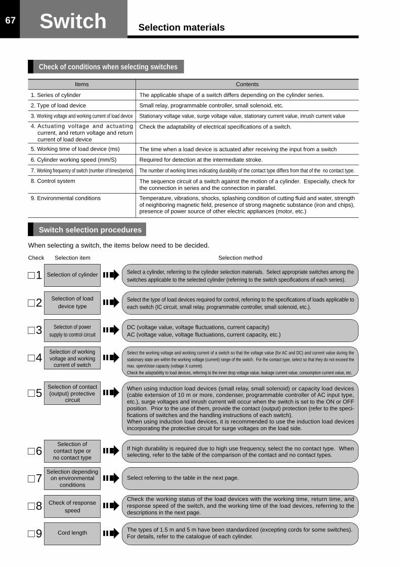
Switch Selection materials67
Contents
The applicable shape of a switch differs depending on the cylinder series.
Small relay, programmable controller, small solenoid, etc.
Stationary voltage value, surge voltage value, stationary current value, inrush current value
Check the adaptability of electrical specifications of a switch.
The time when a load device is actuated after receiving the input from a switch
Required for detection at the intermediate stroke.
The number of working times indicating durability of the contact type differs from that of the no contact type.
The sequence circuit of a switch against the motion of a cylinder. Especially, check forthe connection in series and the connection in parallel.
Temperature, vibrations, shocks, splashing condition of cutting fluid and water, strengthof neighboring magnetic field, presence of strong magnetic substance (iron and chips),presence of power source of other electric appliances (motor, etc.)
When selecting a switch, the items below need to be decided.
1
2
Selection of cylinder
Selection of loaddevice type
Check Selection item Selection method
Check of conditions when selecting switches
Switch selection procedures
Select a cylinder, referring to the cylinder selection materials. Select appropriate switches among theswitches applicable to the selected cylinder (referring to the switch specifications of each series).
Select the type of load devices required for control, referring to the specifications of loads applicable toeach switch (IC circuit, small relay, programmable controller, small solenoid, etc.).
DC (voltage value, voltage fluctuations, current capacity)AC (voltage value, voltage fluctuations, current capacity, etc.)
Select the working voltage and working current of a switch so that the voltage value (for AC and DC) and current value during thestationary state are within the working voltage (current) range of the switch. For the contact type, select so that they do not exceed themax. open/close capacity (voltage X current).Check the adaptability to load devices, referring to the inner drop voltage value, leakage current value, consumption current value, etc.
When using induction load devices (small relay, small solenoid) or capacity load devices(cable extension of 10 m or more, condenser, programmable controller of AC input type,etc.), surge voltages and inrush current will occur when the switch is set to the ON or OFFposition. Prior to the use of them, provide the contact (output) protection (refer to the speci-fications of switches and the handling instructions of each switch).When using induction load devices, it is recommended to use the induction load devicesincorporating the protective circuit for surge voltages on the load side.
If high durability is required due to high use frequency, select the no contact type. Whenselecting, refer to the table of the comparison of the contact and no contact types.
Select referring to the table in the next page.
Check the working status of the load devices with the working time, return time, andresponse speed of the switch, and the working time of the load devices, referring to thedescriptions in the next page.
The types of 1.5 m and 5 m have been standardized (excepting cords for some switches).For details, refer to the catalogue of each cylinder.
3 Selection of powersupply to control circuit
4Selection of workingvoltage and working
current of switch
5Selection of contact(output) protective
circuit
6Selection of
contact type orno contact type
7Selection depending
on environmentalconditions
8 Check of responsespeed
9 Cord length
Items
1. Series of cylinder
2. Type of load device
3. Working voltage and working current of load device
4. Actuating voltage and actuatingcurrent, and return voltage and returncurrent of load device
5. Working time of load device (ms)
6. Cylinder working speed (mm/S)
7. Working frequency of switch (number of times/period)
8. Control system
9. Environmental conditions

SwitchSelection materials68
The places where dangerous materials, including fir-ing and ignitable objects, are present
The places where the atmosphere of chemicals, etc.is present
The places where are subjected to chips
The places where strong magnetic fields aregenerated
When strong magnetic substances (iron, etc.)approach switches or cylinder
The places where are subjected to vibrations andshocks
The places where are subjected to direct sunlight(outdoor)
Environmental conditions
1) Working temperatureUse switches within the ambient temperature range described in the specifications of each switch.
For hydraulic cylinders, oil temperature may be increased depending on the working conditions.Provide some countermeasures in the hydraulic circuit or install an air conditioner.
3) Other environmental conditions
Detectable cylinder piston speed
Notes) Refer to the materials related to the working time of load devices including relays of each manufacturer. Apply the minimum value to the working range of a switch, and apply the maximum value to the working
time of a load device.
Detectable piston speed (mm/s) = × 1000working range of switch (mm)
working time of load device (ms)
Refer to the vibration and shock resistance specifications of eachswitch.
Use only indoors.In the places where are subjected to direct sunlight, provide covers.
DO NOT use under these conditions.
Provide countermeasures referring to the recommended mountinglocations specified in the handling instructions of the switches.
When mounting the switch on the intermediate position, be sure to adjust the maximum cylinder speed to 300 mm/s or slower on account of the response speed of the load relays, etc.
If the piston speed is excessively high, the switch working time becomes shorter, although the switch works, and load devices including relays may not work.Determine the detectable cylinder piston speed, referring to the formula below.
2) Criteria for selection in case that switches are splashed with cutting fluid or water
Conditions
Use the cutting fluid proof type switches (WR, WS types) even if cutting fluid orwater is mist, or they are splashed only several times a day.However, in the case of the use of switches in the places where are splashed withnonaqueous cutting fluid of the type 2, contact us.
DO NOT use even if momentarily.
Criteria for selection
In cutting fluid or water
When switches are splashed withcutting fluid or water always orfrequently

69 Magnetic proximity type(with contact)AX Type Switch
With cord With connector
Applicable hydraulic cylinder
(Brown)
(Blue)
Protectivecircuit
Reed switch
Series Bore
35S-1R
HQS2R
100S-1R
160S-1R
210S-1R
35Z-1R
35H-3R
f20, f25, f32, f40, f50, f63
f32, f40, f50, f63, f80, f100
f32, f40, f50, f63, f80, f100
f32, f40, f50, f63, f80
f32, f40, f50, f63, f80
f20, f25, f32
f32, f40, f50, f63, f80, f100
Series Bore
100Z-1R
100H-2R
70/140H-8R
160H-1R
f20, f25, f32
f32, f40, f50, f63, f80,
f100, f125
f32, f40, f50, f63, f80,
f100, f125, f140
f32, f40, f50, f63, f80,
f100, f125, f140, f160
Series Bore
210C-1R
70/140Y-2R
35P-3R
70/140P-8R
f40, f50, f63, f80
f32, f40, f50, f63, f80,
f100, f125
f32, f40, f50, f63, f80,
f100
f32, f40, f50, f63, f80,
f100
Notes) When using induction load devices (small relay, etc.), be sure to provide the protective circuit (SK-100). For the cord length and connector pin position of the connector type, refer to the dimensional drawings. When using the AC voltage input programmable controller as a load, select the switch with contact protective circuit.
Specifications
Load voltage range
With cord (1.5m)
With cord (5m)
With connector (AC type)
With connector (DC type)
—
AX125——
———
AX11B
——
AX11A—
AX111AX115
——
AX101AX105
——AC : 5 - 120V DC : 5 - 30V AC : 5 - 120V
1ms or less
Small relay • Programmable Controller
Cod
e
DC : 5 - 30V AC: 120 V or less DC: 30 V or less
AC : 2VA DC : 1.5W
0µA
2V (at 10mA) 3V or less (at 40mA)
10µA or less
0V
Maximum open/close capacity
Inner drop voltage
Current leak
Working time
AC : 5 - 20mA DC : 5 - 40mA
1ms or less
0µA
Return time
100 M Ω or more at 500 MV DC (between case and cord)Insulation resistance
Voltage-proof AC1500V 1 min (between case and cord)
Shock resistance
Vibration-proof
Ambient temperature
294m/s2 (Non-repetition)
Wiring method
Protective structure
Total amplitude 1.5mm, 10 - 55Hz (1 sweep, 1 min) 2 hours in X, Y, and Z directions
–10 - +70°C (at non-freezing condition)
0.3mm2 2-core Outer diameter 4mm Oil-proof cabtyre cord
IP67 (IEC standards), JIS C0920 (dusts-proof, immersion-proof type)
Contact protective circuit Note) None Equipped Note) None
NoneIndicating lamp LED (red lamp lights up during ON)
Electric circuit
Applied loadIC circuit, small relay,programmablecontroller
Load current range 5 - 20mA 5 - 40mA AC: 20 mA or less DC: 40 mA or less
-10 - +100°C (at non-freezing condition)
(Brown)
(Blue)Reed switch Reed switch
(Brown)
(Blue)
No polarity ,

10
99
10
30 7 500 44.5
M12
13.5 13φ14.5
φ4
Max. sensitive position
Indicating lamp
3
4
1
2
Connector pin position
(Brown : +)
(Blue : –)
AX101 • AX111:1500AX105 • AX115 • AX125:5000
10
99
10
7
10 7
13.5 13
30
φ4
Max. sensitive position
Indicating lamp
3
4
1
2
(Brown : +) (Blue : –)
Connector pin position
70Magnetic proximity type(with contact) AX Type Switch
Unit: mm
Dimensional Drawing
Cord typeAX101 • AX105AX111 • AX115AX125
Connector typeAX11A • AX11B
AX11A (AC type) AX11B (DC type)
No. of connector standardsModels M12X1 screw locking• IEC 947-5-2• DIN/VDE 0660 part 208 A2• NECA (The Japan Electric Control Equipment Industry Association) 4202
Connector for FA sensor
Manufacturers
Correns Co., Ltd.
Omron Corporation
Hirose Electric Co., Ltd.
VA connectorXS2 sensor I/O connectorConnector for FA sensor
VA-4DS, VA-4DLXS2HR24
Connector series name
Applicable counter connectors
For details, refer to the catalogues of the manufacturers’products.

71
-10 - +100°C (at non-freezing condition)
Series Bore
35S-1R
HQS2R
100S-1R
160S-1R
210S-1R
35Z-1R
35H-3R
f20, f25, f32, f40, f50, f63
f32, f40, f50, f63, f80, f100
f32, f40, f50, f63, f80, f100
f32, f40, f50, f63, f80
f32, f40, f50, f63, f80
f20, f25, f32
f32, f40, f50, f63, f80, f100
Series Bore
100Z-1R
100H-2R
70/140H-8R
160H-1R
f20, f25, f32
f32, f40, f50, f63, f80,
f100, f125
f32, f40, f50, f63, f80,
f100, f125, f140
f32, f40, f50, f63, f80,
f100, f125, f140, f160
Series Bore
210C-1R
70/140Y-2R
35P-3R
70/140P-8R
f40, f50, f63, f80
f32, f40, f50, f63, f80,
f100, f125
f32, f40, f50, f63, f80,
f100
f32, f40, f50, f63, f80,
f100
Notes) When using induction load (including a small relay) for the switch without contact protective circuit, be sure to provide theprotective circuit (SK-100) for the load.
For the cord length and connector pin position of the connector type, refer to the dimensional drawings. When using the AC voltage input programmable controller as a load, select the switch with contact protective circuit.
Specifications
Load voltage range
With cord (1.5m)
With cord (5m)
With connector (AC type)
With connector (DC type)
—
AZ125——
———
AZ11B
——
AZ11A—
AZ111AZ115
——
AZ101AZ105
——AC : 5 - 120V DC : 5 - 30V AC : 5 - 120V
1ms or less
Small relay • Programmable Controller
Cod
e
DC : 5 - 50V
AC : 2VA DC : 1.5W
0µA
2V (at 10mA) 3V or less (at 40mA)
10µA or less
0V
Maximum open/close capacity
Inner drop voltage
Current leak
Working time
AC : 5 - 20mA DC : 5 - 40mA
1ms or less
0µA
Return time
100 M Ω or more at 500 MV DC (between case and cord)Insulation resistance
Voltage-proof AC1500V 1 min (between case and cord)
Shock resistance
Vibration-proof
Ambient temperature
294m/s2 (30G) (Non-repetition)
Wiring method
Protective structure
Total amplitude 1.5mm, 10 - 55Hz (1 sweep, 1 min) 2 hours in X, Y, and Z directions
–10 - +70°C (at non-freezing condition)
0.3mm2 2-core Outer diameter 4mm Oil-proof cabtyre cord
IP67 (IEC standards), JIS C0920 (dusts-proof, immersion-proof type)
Contact protective circuit Note) None Equipped Note) None
NoneIndicating lamp LED (red lamp lights up during ON)
Electric circuit
Applied loadIC circuit, small relay,programmablecontroller
Load current range 5 - 20mA 5 - 40mA
(Brown)
(Blue)Reed switch
(Brown)
(Blue)
Protectivecircuit
Reed switchReed switch
(Brown)
(Blue)
No polarity ,
AC: 120 V or less DC: 30 V or less
AC: 20 mA or less DC: 40 mA or less
Applicable hydraulic cylinder
Magnetic proximity type(with contact)AZ Type Switch
With cord With connector

9
13.5
9 10
10 30
13
20 44.5
φ4
φ14.5M12
500
Max. sensitive position
Indicating lamp
3
4
1
2
Connector pin position
(Brown : +)
(Blue : –)
13.5
13
9
9
10
10 30φ4
10 7
20AZ101 • AZ111:1500
AZ105 • AZ115 • AZ125:5000
Max. sensitive position
Indicating lamp
3
4
1
2
(Brown : +) (Blue : –)
Connector pin position
72Magnetic proximity type(contact type) AZ Type Switch
Unit: mm
AZ11A (AC type) AZ11B (DC type)
No. of connector standardsModels M12X1 screw locking• IEC 947-5-2• DIN/VDE 0660 part 208 A2• NECA (The Japan Electric Control Equipment Industry Association) 4202
Connector for FA sensor
Manufacturers
Correns Co., Ltd.
Omron Corporation
Hirose Electric Co., Ltd.
VA connectorXS2 sensor I/O connectorConnector for FA sensor
VA-4DS, VA-4DLXS2HR24
Connector series name
Applicable counter connectors
For details, refer to the catalogues of the manufacturers’products.
Dimensional Drawing
Cord typeAZ101 • AZ105AZ111 • AZ115AZ125
Connector typeAZ11A • AZ11B

73
Rear wiringDC : 5 - 30V
DC : 30 V or lessMax. 200mA (NPN open collector output)
Max. 15mAAt 200 mA, 0.6 V max.At 30 V DC, 10µA max.
1 ms or shorter1 ms or shorter
100 MΩ or more at 500 MV DC (between case and cord)AC 1500 V, 1 min (between case and cord)
490m/s2 (Non-repetition)Total amplitude 0.6 mm, 10 Hz to 200 Hz (log sweep 1 hour) in X, Y, and Z directions
-10°C to +70°C (at non-freezing condition)0.3 mm2 3-core Outer diameter 4 mm Oil-proof cabtyre cord
IP67 (IEC standards), JIS C0920 (dust-proof, immersion-proof type)Equipped
LED (red lamp lights up during ON)
Specifications
Wiring directionPower supply voltage rangeLoad voltage rangeLoad currentConsumption currentInner drop voltageLeak currentWorking timeReturn timeInsulation resistanceVoltage-proofShock resistanceVibration-proofAmbient temperatureWiring methodProtective structureProtective circuitIndicating lamp
Electric circuit
Applied load
With cord (1.5m)With cord (5m)
AX221AX225
IC circuit, small relay, programmable controller
Cod
e
LED
Transistor
Output (OUT, black)
GND (-, blue)
Power supply (+, brown)
Sw
itch
mai
n ci
rcui
t
Series Bore
35S-1R
HQS2R
100S-1R
160S-1R
210S-1R
35Z-1R
35H-3R
f20, f25, f32, f40, f50, f63
f32, f40, f50, f63, f80, f100
f32, f40, f50, f63, f80, f100
f32, f40, f50, f63, f80
f32, f40, f50, f63, f80
f20, f25, f32
f32, f40, f50, f63, f80, f100
Series Bore
100Z-1R
100H-2R
70/140H-8R
160H-1R
f20, f25, f32
f32, f40, f50, f63, f80,
f100, f125
f32, f40, f50, f63, f80,
f100, f125, f140
f32, f40, f50, f63, f80,
f100, f125, f140, f160
Series Bore
210C-1R
70/140Y-2R
35P-3R
70/140P-8R
f40, f50, f63, f80
f32, f40, f50, f63, f80,
f100, f125
f32, f40, f50, f63, f80,
f100
f32, f40, f50, f63, f80,
f100, f125
Applicable hydraulic cylinder
Magnetic proximity type(No contact/Three-wire one-lamp type)AX Type Switch
With cord

AX201:1500AX205:5000
φ4
10
99
10
7
10 7
13.5 13
30
Max. sensitive position
Indicating lamp
74Magnetic proximity type(No contact/Three-wire one-lamp type) AX Type Switch
Unit: mm
Dimensional Drawing
Cord typeAX221 • AX225

75
DC : 5 - 30VDC : 5 - 40 mA
3 V or less (at 40 mA)0.7 mA or less1 ms or shorter1 ms or shorter
100 MΩ or more at 500 MV DC (between case and cord)AC 1500 V, 1 min. (between case and cord)
490m/s2 (Non-repetition)Total amplitude 0.6 mm, 10 Hz to 200 Hz (log sweep 1 hour) in X, Y, and Z directions
-10°C to +70°C (at non-freezing condition)0.3 mm2 2-core Outer diameter 4 mm Oil-proof cabtyre cord
IP67 (IEC standards), JIS C0920 (dust-proof, immersion-proof type)\Equipped
LED (red lamp lights up during ON)
Wiring directionLoad voltage rangeLoad current rangeInner drop voltageLeak currentWorking timeReturn timeInsulation resistanceVoltage-proofShock resistanceVibration-proofAmbient temperatureWiring methodProtective structureContact protective circuitIndicating lamp
Electric circuit
Applied load
AX201AX205AX20B
Rear wiring
Small relay, programmable controller
Switch main circuit
LED Transistor
Output (Brown)
GND (Blue)
SpecificationsWith cord (1.5m)With cord (5m)With connector
Cod
e
Applicable hydraulic cylinder
Series Bore
35S-1R
HQS2R
100S-1R
160S-1R
210S-1R
35Z-1R
35H-3R
f20, f25, f32, f40, f50, f63
f32, f40, f50, f63, f80, f100
f32, f40, f50, f63, f80, f100
f32, f40, f50, f63, f80
f32, f40, f50, f63, f80
f20, f25, f32
f32, f40, f50, f63, f80, f100
Series Bore
100Z-1R
100H-2R
70/140H-8R
160H-1R
f20, f25, f32
f32, f40, f50, f63, f80,
f100, f125
f32, f40, f50, f63, f80,
f100, f125, f140
f32, f40, f50, f63, f80,
f100, f125, f140, f160
Series Bore
210C-1R
70/140Y-2R
35P-3R
70/140P-8R
f40, f50, f63, f80
f32, f40, f50, f63, f80,
f100, f125
f32, f40, f50, f63, f80,
f100
f32, f40, f50, f63, f80,
f100
Magnetic proximity type(No contact/Two-wire one-lamp type)AX Type Switch
With cord With connector

76Magnetic proximity type(No contact/Two-wire one-lamp type) AX Type Switch
Unit: mm
AX20B (DC type)
No. of connector standardsModels M12X1 screw locking• IEC 947-5-2• DIN/VDE 0660 part 208 A2• NECA (The Japan Electric Control Equipment Industry Association) 4202
Connector for FA sensor
Manufacturers
Correns Co., Ltd.
Omron Corporation
Hirose Electric Co., Ltd.
VA connectorXS2 sensor I/O connectorConnector for FA sensor
VA-4DS, VA-4DLXS2HR24
Connector series name
Applicable counter connectors
For details, refer to the catalogues of the manufacturers’products.
Dimensional Drawing
Cord typeAX201 • AX205
Connector typeAX20B
10
99
10
30 7 500 44.5
M12
13.5 13φ14.5
φ4
Max. sensitive position
Indicating lamp
3
4
1
2
Connector pin position
(Brown : +)
(Blue : –)
AX201:1500AX205:5000
φ4
10
99
10
7
10 7
13.5 13
30
Max. sensitive position
Indicating lamp

77 Magnetic proximity type(No contact/Two-wire one-lamp type)AZ Type Switch
With cord With connector
Switch main circuit
LED Transistor
Output (Brown)
GND (Blue)
DC : 5 - 30VDC : 5 - 40 mA
3 V or less (at 40 mA)0.7 mA or less1 ms or shorter1 ms or shorter
100 MΩ or more at 500 MV DC (between case and cord)AC 1500 V, 1 min. (between case and cord)
490m/s2 (Non-repetition)Total amplitude 0.6 mm, 10 Hz to 200 Hz (log sweep 1 hour) in X, Y, and Z directions
-10°C to +70°C (at non-freezing condition)0.3 mm2 2-core Outer diameter 4 mm Oil-proof cabtyre cord
IP67 (IEC standards), JIS C0920 (dust-proof, immersion-proof type)Equipped
LED (red lamp lights up during ON)
Wiring directionLoad voltage rangeLoad current rangeInner drop voltageLeak currentWorking timeReturn timeInsulation resistanceVoltage-proofShock resistanceVibration-proofAmbient temperatureWiring methodProtective structureContact protective circuitIndicating lamp
Electric circuit
Applied load
AZ201AZ205AZ20B
Upper wiring
Small relay, programmable controller
SpecificationsWith cord (1.5m)With cord (5m)With connectorC
ode
Applicable hydraulic cylinder
Series Bore
35S-1R
HQS2R
100S-1R
160S-1R
210S-1R
35Z-1R
35H-3R
f20, f25, f32, f40, f50, f63
f32, f40, f50, f63, f80, f100
f32, f40, f50, f63, f80, f100
f32, f40, f50, f63, f80
f32, f40, f50, f63, f80
f20, f25, f32
f32, f40, f50, f63, f80, f100
Series Bore
100Z-1R
100H-2R
70/140H-8R
160H-1R
f20, f25, f32
f32, f40, f50, f63, f80,
f100, f125
f32, f40, f50, f63, f80,
f100, f125, f140
f32, f40, f50, f63, f80,
f100, f125, f140, f160
Series Bore
210C-1R
70/140Y-2R
35P-3R
70/140P-8R
f40, f50, f63, f80
f32, f40, f50, f63, f80,
f100, f125
f32, f40, f50, f63, f80,
f100
f32, f40, f50, f63, f80,
f100

78Magnetic proximity type(No contact/Two-wire one-lamp type) AZ Type Switch
Unit: mm
AZ20B (DC type)
No. of connector standardsModels M12X1 screw locking• IEC 947-5-2• DIN/VDE 0660 part 208 A2• NECA (The Japan Electric Control Equipment Industry Association) 4202
Connector for FA sensor
Manufacturers
Correns Co., Ltd.
Omron Corporation
Hirose Electric Co., Ltd.
VA connectorXS2 sensor I/O connectorConnector for FA sensor
VA-4DS, VA-4DLXS2HR24
Connector series name
Applicable counter connectors
For details, refer to the catalogues of the manufacturers’products.
Dimensional Drawing
Cord typeAZ201 • AZ205
Connector typeAZ20B
9
13.5
9 10
10 30
13
20 44.5
φ4
φ14.5M12
500
Max. sensitive position
Indicating lamp
3
4
1
2
Connector pin position
(Brown : +)
(Blue : –)
13.5
13
9
9
10
10 30φ4
10 7
20AZ201:1500AZ205:5000
Max. sensitive position
Indicating lamp

79 Magnetic proximity type(No contact/Two-wire two-lamp type)AX Type Switch
With cord With connector
Specifications
Wiring directionLoad voltage rangeLoad current rangeInner drop voltageLeak currentWorking timeReturn timeInsulation resistanceVoltage-proofShock resistanceVibration-proofAmbient temperatureWiring methodProtective structureContact protective circuitIndicating lamp
Electric circuit
Applied load
With cord (1.5m)With cord (5m)
With connector
AX211
AX215AX21C
AX21DRear wiring
Small relay, programmable controller
DC : 5 - 30VDC : 5 - 40 mA
3 V or less (at 40 mA)0.7 mA or less1 ms or shorter1 ms or shorter
100 MΩ or more at 500 MV DC (between case and cord)AC 1500 V, 1 min. (between case and cord)
490m/s2 (Non-repetition)Total amplitude 0.6 mm, 10 Hz to 200 Hz (log sweep 1 hour) in X, Y, and Z directions
-10°C to +70°C (at non-freezing condition)0.3 mm2 2-core Outer diameter 4 mm Oil-proof cabtyre cord
IP67 (IEC standards), JIS C0920 (dust-proof, immersion-proof type)Equipped
Working position: Red/green LED lights up Most suitable position: Green LED lights up
LED
Switch main circuit
Transistor
Output (Brown)
GND (Blue)
OFF
ON
Best adjustment range
Max. sensitive positionWorking range
Red RedGreenLED indicating style (Two-wire, two-lamp type)
Note) AX211CE, AX215CE, and AX21BCE confirming to CE standards are also available.
Applicable hydraulic cylinder
Cod
e
Series Bore
35S-1R
HQS2R
100S-1R
160S-1R
210S-1R
35Z-1R
35H-3R
f20, f25, f32, f40, f50, f63
f32, f40, f50, f63, f80, f100
f32, f40, f50, f63, f80, f100
f32, f40, f50, f63, f80
f32, f40, f50, f63, f80
f20, f25, f32
f32, f40, f50, f63, f80, f100
Series Bore
100Z-1R
100H-2R
70/140H-8R
160H-1R
f20, f25, f32
f32, f40, f50, f63, f80,
f100, f125
f32, f40, f50, f63, f80,
f100, f125, f140
f32, f40, f50, f63, f80,
f100, f125, f140, f160
Series Bore
210C-1R
70/140Y-2R
35P-3R
70/140P-8R
f40, f50, f63, f80
f32, f40, f50, f63, f80,
f100, f125
f32, f40, f50, f63, f80,
f100
f32, f40, f50, f63, f80,
f100

80Magnetic proximity type(No contact/Two-wire two-lamp type) AX Type Switch
Unit: mm
AX21C • AX21D (DC type)
As for the connector pin layout conforming to the IEC standards (1:+4:-), contact us. AX21B conforming to TMS standards is also available.
Manufacturers
Correns Co., Ltd.
Omron Corporation
Hirose Electric Co., Ltd.
VA connectorXS2 sensor I/O connectorConnector for FA sensor
VA-4DS, VA-4DLXS2HR24
Connector series name
Applicable counter connectors
For details, refer to the catalogues of the manufacturers’products.
Dimensional Drawing
Cord typeAX211 • AX215
Connector typeAX21C • AX21D
TMS standards conforming type
10
99
10
30 7 44.5
M12
13.5 13φ14.5
φ4
AX21C:500AX21D:1000
Max. sensitive position
Indicating lamp
3
4
1
2
(Brown : +)(Blue : –)
Connector pin position
AX211:1500AX215:5000
φ4
10
99
10
7
10 7
13.5 13
30
Max. sensitive position
Indicating lamp

81 Magnetic proximity type(No contact/Two-wire two-lamp type)AZ Type Switch
With cord With connector
Specifications
Wiring directionLoad voltage rangeLoad current rangeInner drop voltageLeak currentWorking timeReturn timeInsulation resistanceVoltage-proofShock resistanceVibration-proofAmbient temperatureWiring methodProtective structureContact protective circuitIndicating lamp
Electric circuit
Applied load
With cord (1.5m)With cord (5m)
With connector
AZ211
AZ215AZ21C
AZ21DUpper wiring
Small relay, programmable controller
DC : 5 - 30VDC : 5 - 40 mA
3 V or less (at 40 mA)0.7 mA or less1 ms or shorter1 ms or shorter
100 MΩ or more at 500 MV DC (between case and cord)AC 1500 V, 1 min. (between case and cord)
490m/s2 (Non-repetition)Total amplitude 0.6 mm, 10 Hz to 200 Hz (log sweep 1 hour) in X, Y, and Z directions
-10°C to +70°C (at non-freezing condition)0.3 mm2 2-core Outer diameter 4 mm Outer diameter Oil-proof cabtyre cord
IP67 (IEC standards), JIS C0920 (dust-proof, immersion-proof type)Equipped
Working position: Red/green LED lights up Most suitable position: Green LED lights up
LED indicating style(Two-wire, two-lamp type)
Applicable hydraulic cylinder
Cod
e
LED
Switch main circuit
Transistor
Output (Brown)
GND (Blue)
OFF
ON
Best adjustment range
Max. sensitive positionWorking range
Red RedGreen
Series Bore
35S-1R
HQS2R
100S-1R
160S-1R
210S-1R
35Z-1R
35H-3R
f20, f25, f32, f40, f50, f63
f32, f40, f50, f63, f80, f100
f32, f40, f50, f63, f80, f100
f32, f40, f50, f63, f80
f32, f40, f50, f63, f80
f20, f25, f32
f32, f40, f50, f63, f80, f100
Series Bore
100Z-1R
100H-2R
70/140H-8R
160H-1R
f20, f25, f32
f32, f40, f50, f63, f80,
f100, f125
f32, f40, f50, f63, f80,
f100, f125, f140
f32, f40, f50, f63, f80,
f100, f125, f140, f160
Series Bore
210C-1R
70/140Y-2R
35P-3R
70/140P-8R
f40, f50, f63, f80
f32, f40, f50, f63, f80,
f100, f125
f32, f40, f50, f63, f80,
f100
f32, f40, f50, f63, f80,
f100

82Magnetic proximity type(No contact/Two-wire two-lamp type) AZ Type Switch
Unit: mm
AZ21C • AX21D (DC type)
Manufacturers
Correns Co., Ltd.
Omron Corporation
Hirose Electric Co., Ltd.
VA connectorXS2 sensor I/O connectorConnector for FA sensor
VA-4DS, VA-4DLXS2HR24
Connector series name
Applicable counter connectors
For details, refer to the catalogues of the manufacturers’products.
Dimensional Drawing
Cord typeAZ211 • AZ215
Connector typeAZ21C • AZ21D
TMS standards conforming type
9
13.5
9 10
10 30
13
20 44.5
φ4
φ14.5M12
AZ21C: 500AZ21D:1000
Max. sensitive position
Indicating lamp
3
4
1
2
(Brown : +)(Blue : –)
Connector pin position
13.5
13
9
9
10
10 30φ4
10 7
20AZ211:1500AZ215:5000
Max. sensitive position
Indicating lamp


WR/WS type switches.........85
Switch specificationsMagnetic proximity type(Cutting oil proof type)

WR·WS type switches Magnetic proximity switch (Cutting oil proof type)
Wiring direction
Load voltage range
Load current range
Inner drop voltage
Max. load capacity
Leak current
Working time
Return time
Insulation resistance
Voltage-proof
Shock resistance
Vibration-proof
Ambient temperature
Wiring method
Protective structure
Indicating lamp
Electric circuit
Applied load
Type
Reliable sealingperformance even inenvironment directlysubject to cutting oil.• Protective structure IP67G.• Standardized flexible tube for protec-
tion of cabtyre cords.• Longer service life even in environ-
ment directly subject to cutting oil(approx. ten times longer than ourconventional product).
• Oil proof type soft PVC used for coat-ing of flexible tube.
• Upper wiring and cord type (withoutflexible tube) are added to allow se-lection appropriate for purposes.
• No contact type with two wires en-ables saving of wiring. Adoption oftwo lamps enables easier setting ofthe optimum fixing position.
Note) When using the induction load (small relay, etc.), be sure to install theprotective circuit (SK-100) to the load.
Unit: mmStructure of flexible tube
Flexible tube: F-05
Connector: F-FC
SwitchStraight box connector: F-SB
4.8m(Optional: F-05)
Bore: φ6mmOuter dia.: φ9mm
Connector: F-KC
w/ cord (5 m)
Contact type No contact
WR505, WR515,WR525, WR545
WR535, WR555
Rear
Switch specifications
Upper
WS215, WS225,WS235, WS255
WS245, WS265
Rear Upper
AC: 5 - 120V DC: 5 - 50V
AC: 3 - 20mA DC: 3 - 40mA
2V or less
DC1.5W • AC2VA
0µA
4V or less
-
1mA or less
1ms or less
1ms or less
100 MΩ or more at 500 MV DC (between case and cord)
AC 1500 V, 1 min. (between case and cord)
294m/s2 (Non-repetition)
Vibration width 1.5 mm, from 10Hz to 55 Hz (1 sweep, 1 min.) 2hours in X, Y, and Z directions
490m/s2 (Non-repetition)
Vibration width 0.6 mm, from 10Hz to 200 Hz, log sweep 1 hour
in X, Y, and Z directions
-10 to + 60°C (at non-freezing condition)
0.3mm2 2-core Outer diameter 4 mm Oil-proof cabtyre cord
IP67G (JEN standards) (Oil proof type)
Red LED lights upWorking position: Red/Green LEDOptimum position: Green LED
Small relay, programmable controller
• Switch typeFlexible tube typeContactWR505, WR525, WR545 (Rear)WR535, WR555 (Upper)No contactWS215, WS235, WS255 (Rear)WS245, WS265 (Upper)
• Flexible tubeCode: F-05(Selling unit: 4.8 m)
Cord typeContact WR515No contact WS225
• For the flexible tube type, be sure to use the switch together with the flexible tube.
• For the flexible tube type, the straight box connector (F-SB) is normally equipped with
the switch.
• Note that the flexible tube type (F-05) must be ordered separately.
Switch shapes depend on the models.
Reed switch
Diode
Brown
Blue
LEDZener diode
Switch main circuit
(Brown)
(Red)(Green) (Blue)
DC10 - 30V
6 - 70mA
Contact
85

WR·WS type switchesMagnetic proximity switch (Cutting oil proof type)
Applicable actuator and mounting bracket list
Notes) • The -marked actuators are of the cutting oil proof type. The WR and WS type switches can be provided for them as the standardoutfits.
• As for the actuators other than the -marked ones, the WR and WS type switches can be provided as the semi-standard outfits.• Before using the WR or WS type switch for the actuators other than the -marked ones, check the operating environment, and
select appropriate switch.
R21 WR505 -H
Bracket (band) code Switch type
<Code example>
86
-
-
-
-
-
-
-
-
-
-
WR525WS235
(Rear wiring)
-
-
R21WR (WS) -HR21WR (WS) -H
R22WR (WS) -H
R22WR (WS) -H
R23WR (WS) -H
R23WR (WS) -H
-
-
160S-1R160SW-1R
35S-1R35SY-1R
Hydraulic actuator
WR505 WS215 (Flexible tube type)
WR515 WS225 (Cord type)WR535WS245
(Upper wiring)
-
-
-
-
-
-
T07WR (WS) -H
70/140H-8R70/140HW-8R70/140Y-2R70/140YW-2R
35H-3R100H-2R100H-2RD100HW-2R
Switch type
Bore
φ20
φ25
φ32
φ40
φ50
φ63
φ80
φ100
φ125
φ140
φ160
Actuatorseries
-
-
R22WR (WS) -H
R23WR (WS) -H
R24WR (WS) -H
R25WR (WS) -H
R26WR (WS) -H
-
-
-
-
-
-
HQS2RHQSW2R100S-1R
100SW-1R

A
φ9
Maximum sensitivity position
15 (Width across flats)
18φ16.512.3
1378
45.5
15
4.5
25
Indicator lamp
A
φ9 18φ16.59
1378
45.5
15
4.5
24
Maximum sensitivity position
15 (Width across flats)Indicator lamp
Dimensional drawings
[Rear wiring]
[Rear wiring]
[Rear wiring]
A
WR (Contact)
WS (No contact)
12
10
A
WR (Contact)
WS (No contact)
12
10
A
WR (Contact)
WS (No contact)
12
10
WR·WS type switches
45.5
15
A
φ9 18φ16.5
Maximum sensitivity position
15 (Width across flats
Indicator lamp
WR505 (Contact)WS215 (No contact)
WR525 (Contact)WS235 (No contact)
WR545 (Contact)WS255 (No contact)
Magnetic proximity switch (Cutting oil proof type)
A
φ6
Maximum sensitivity position
1812.3
137
8
43.5
15
4.5
25
Indicator lamp
15 (Width across flats)
46
30
15
16.5
A
18
φ9
29
Maximum sensitivity position
Indicator lamp
A
18
φ9
29
9
84.5
46137
2415
φ16.
5
15 (Width across flats)
Maximum sensitivity position
Indicator lamp
WR515 (Contact)WS225 (No contact)
WR535 (Contact)WS245 (No contact)
WR555 (Contact)WS265 (No contact)
[Cord type]
[Upper wiring]
[Upper wiring]
A
WR (Contact)
WS (No contact)
12
10
A
WR (Contact)
WS (No contact)
12
10
A
WR (Contact)
WS (No contact)
12
10
Unit: mm
87

• Connector parts configuration
• Mounting to switch
• Connector parts configuration
• Mounting to switch
1. Cut the flexible tube at the required length (Avoid anyburr and deformation on the cut surface. Otherwise, theterminal cap may not be able to be fit).
2. Insert the jam nut , ring washer seal packing , andterminal cap into the flexible tube in this order (Insertthe terminal cap into the bore of the flexible tube ).
3. From the terminal cap side, pass the cord throughthe flexible tube with the parts from to inserted.
4. Insert the unit above into the switch bush , and tightenthe jam nut onto the threads of the switch bush .
5. Tighten the jam nut until its end face comes in contactwith the width across flats of the switch bush (in thearrow direction). Then, the mounting is complete.
* When tightening the jam nut , wrench the width acrossflats of the switch bush with a spanner.
WR·WS type switchesMagnetic proximity switch (Cutting oil proof type)
Switch Switch bush Terminal capF-TC
Seal packingF-SP
Ring washerF-RW
Jam nutF-JN1 2
3 4 5 6
Width across flats
Cord
Flexible tubeF-05
8
7
Fully contact
Turn
Spanner
Jam nut6
Turn
Lock nutF-RN
Body packingF-BP
Nipple bodyF-NB
Seal packingF-SP
Ring washerF-RW
Jam nutF-JN
Terminal capF-TC
1 2 3 4 5 6 7
Fully contact
Flexible tubeF-05
8
Lock nutF-RN
M14×1Width across flats 17 Width
across flats 19Interruption box or panel
(plate thickness: 1 to 5 mm)
Body packingF-BP
10
212.5
12
*In the case of the mounting to panels, etc., the mounting hole dia. must be φ15.
Switch Switch bush Bush capF-BC
Rubber bushF-GB
Ring washerF-RW
Connector: F-KC
1 23 4 5
Width across flats
Cord 6
Handling instructions
Horizontal type Vertical type
Straight box connector and flexible tube
• Mounting to straight box connector (F-SB)
1. Insert the jam nut , ring washer , seal packing , andterminal cap into the flexible tube in this order (screw theterminal cap into the bore of the flexible tube ).
2. Insert the end of the flexible tube with the parts from to inserted into the threads of the nipple body , and tighten
the jam nut onto the threads of the nipple body .3. Tighten the jam nut until its end face comes in contact with
the end face of the width across flats of the nipple body (inthe arrow direction). Then, the mounting is complete.
1. Pass the cord through the rubber bush , ring washer , andbush cap in this order.
2. Insert the parts passed through the cord into the switch bush , andtighten the bush cap onto the thread of the switch bush .
3. Tighten the bush cap until its end face comes in contact with theend face of the width across flats of the switch bush (in the arrowdirection). Then, the mounting is com-plete.
* When tightening the bush cap , holdthe width across flats of the switch bush
with a spanner, and tighten withhands.
Fully contact
Turn
Spanner
S
88
Switch and flexible tube
• Parts of straight box connector (F-SB)
• Sectional drawing of completed mounting to straightbox connector (F-SB)
Cord type

Switch list Switch and bracket assembly89
10 MPa double-acting type hydraulic cylinder
R32
R33
R34
R35
R36
R32
R33
R34
R35
R36
R21-H
R22-H
R22-H
R32AX2
R33AX2
R34AX2
R35AX2
R36AX2
R32AZ2
R33AZ2
R34AZ2
R35AZ2
R36AZ2
R21WS -H
R22WS -H
R22WS -H
R32AX1
R33AX1
R34AX1
R35AX1
R36AX1
R32AZ1
R33AZ1
R34AZ1
R35AZ1
R36AZ1
R21WR -H
R22WR -H
R22WR -H
φ32 • φ40
φ50 • φ63
φ80
φ100
φ125
φ32 • φ40
φ50 • φ63
φ80
φ100
φ125
φ32 • φ40
φ50 • φ63
φ80
AX type AX1
No contactGeneral purpose type• 2-wire, 1-lamp typeCord rear wiringBE: AX201 (with 1.5 m cord)BF: AX205 (with 5 m cord)Cord upper wiringBM: AZ201 (with 1.5 m cord)BN: AZ205 (with 5 m cord)• 2-wire, 2-lamp typeCord rear wiringCE: AX211 (with 1.5 m cord)CF: AX215 (with 5 m cord)Cord upper wiringCM: AZ211 (with 1.5 m cord)CN: AZ215 (with 5 m cord)• 3-wire, 1-lamp typeCord rear wiringBH: AX221 (with 1.5 m cord)BJ: AX225 (with 5 m cord)Cord upper wiringBR: AZ221 (with 1.5 m cord)BS: AZ225 (with 5 m cord)Cutting oil proof type2: WS215 (2-lamp type w/ 5 m cord)4: WS215F (2-lamp type w/ 5 m cord/flexible tube attached)3: WS225 (2-lamp type w/ 5 m cord)
Symbol/code for order of switches Contact
General purpose typeCord rear wiringAF: AX101 (with 1.5 m cord)AG: AX105 (with 5 m cord)AH: AX111 (with 1.5 m cord)AJ: AX115 (with 5 m cord)AE : AX125 (with 5 m cord/no lamp)AK: AX11A (connector type/AC)AL : AX11B (connector type/DC)Cord upper wiringAP : AZ101 (with 1.5 m cord)AR: AZ105 (with 5 m cord)AS : AZ111 (with 1.5 m cord)AT : AZ115 (with 5 m cord)AN: AZ125 (with 5 m cord/no lamp)AU: AZ11A (connector type/AC)AW: AZ11B (connector type/DC)Cutting oil proof type5: WR505 (with 5 m cord)7: WR505F (with 5 m cord/flexible tube attached)6: WR515 (with 5 m cord)
CE standard No contact
General purpose type• 2-wire, 2-lamp typeCord rear wiringCT: AX211CE (with 1.5 m cord)CU: AX215CE (with 5 m cord)CV: AX21B (connector type/DC)Cord upper wiringCW: AZ211CE (with 1.5 m cord)CX: AZ215CE (with 5 m cord)CY: AZ21B (connector type/DC)
AX2
AZ type
WR type • WS type
AZ1 AZ2
WR -H WS -H
Switch type
Switch bracket assembly model code Code for order of switches and bracket
assemblies Code for order of
bracket bands
Bracket band symbol
R32AX111
Switch type
AX111R32
Bracket band symbol
Code for order ofswitches
100H-2R ••••• 100HW-2R
No contactContactNo contactContactBoreSwitch type
Assy type Switch single unit type Brackettype

List of seals

100H-2 Sectional drawings/List of seals
Double acting single rod/Standard type/100H-2
Seal material: 2 Urethane rubber, 8 combined seal
Double acting single rod/Switch set/100H-2R
Seal material: 2 Urethane rubber, 8 combined seal
293027
2528
32
31
26
293027
2528
32
31
26
91

Sectional drawings/List of seals 100H-2
Double acting single rod/Standard type/100H-2
Seal material: 1 Nitrile rubber, 6 Hydrogenated nitrile rubber
Double acting single rod/Switch set/100H-2R
Seal material: 1 Nitrile rubber, 6 Hydrogenated nitrile rubber
28
26
31 25
3227 30 29
293027 32
2531
26
28
92

100H-2 Sectional drawings/List of seals
2
1
1
2
1
1
1
1
2
1 set
1 set
No.
Piston seal
Rod seal
Wiper ring
Cover seal
O-ring for cushion ring
O-ring for bush
Valve seal
φ32
TT-32
S-12.5
P-15
S-15
P-21
CX-8H
RH1/PKS1-032B
φ40 φ50 φ63
RH1R/PKS1-032B
OUHR32 25 5
IUH18 25 5
LBH18 24 3.5 4.5
OUHR40 32 5.4
IUH22 29 5
LBH22 28 3.5 4.5
OUHR50 42 5.4
IUH28 36 5.4
LBH28 36 4.5 6
OUHR63 55 5.4
IUH36 44 5.4
LBH36 44 4.5 6
TT-40
P-18
P-15
S-18
G-25
CX-8H
TT-50
P-22
P-18
P-22
G-30
CX-8H
TX-63
G-30
G-25
G-30
G-40
CX-8H
QH2/PKS1-040B
QH2R/PKS1-040B
QH2/PKS1-050B
QH2R/PKS1-050B
QH2/PKS1-063B
QH2R/PKS1-063B
O-ring for pistonrod
2
1
1
2
1
1
1
1
2
1 set
1 set
No.
Piston seal
Rod seal
Wiper ring
Cover seal
O-ring for cushion ring
O-ring for bush
Valve seal
φ80
TX-80
G-40
G-35
G-40
G-50
CX-12H
QH2/PKS1-080B
φ100 φ125
(w/o switch)
(w/ switch)
QH2R/PKS1-080B
OUHR80 70 6.5
IUH45 53
5.4
LBH45 53 4.5 6
OUHR100 90 6.5
IUH56 66
6.5
LBH56 66 5 6.5
OUHR125 110 9.6
IUH70 80 6.5
LBH70 80 5 6.5
TX-100
G-50
G-45
G-50
G-60
CX-12H
TX-125
G-65
G-55
G-65
G-80
CX-14H
QH2/PKS1-100B
QH2R/PKS1-100B
QH2/PKS1-125B
QH2R/PKS1-125B
O-ring for pistonrod
S-12.5 is made of hydrogenated nitrile rubber with hardness of 70. Other O-rings conform to JIS B 2401-1A.Note) Nominal seal models are subject to change.
93
Sea
l kit
Parts name Material Q'ty.Parts code
S
eal k
it
(w/o switch)
(w/ switch)
100H-2(standard type)
100H-2R(switch set)
Hydrogenated nitrilerubber
Hydrogenated nitrilerubber
Hydrogenated nitrilerubber
Nitrile rubber
Nitrile rubber
Nitrile rubber
Nitrile rubber
Nitrile rubber
Canned hydrogenatednitrile rubber
1 Nitrile rubber/100H-2, 100H-2RSeal kit
Hydrogenated nitrilerubber
Hydrogenated nitrilerubber
Hydrogenated nitrilerubber
Canned hydrogenatednitrile rubber
Parts name Material Q'ty.Parts code
100H-2 (standard type)
100H-2R(switch set)
Nitrile rubber
Nitrile rubber
Nitrile rubber
Nitrile rubber
Nitrile rubber
@5
@6
@7
@8
@9
#0
#1
#2
@5
@6
@7
@8
@9
#0
#1
#2

Sectional drawings/List of seals 100H-2
1
1
1
2
1
1
1
1
2
1 set
1 set
No.
Piston seal
Rod seal
Wiper ring
Cover seal
O-ring for cushion ring
O-ring for bush
Valve seal
TT-32
S-12.5
S-12.5
S-15
P-21
CX-8H
RH1/PKS2-032B
RH1R/PKS2-032B
KR003200701
B31826P5008
AY1080P5008
TT-40
P-18
P-15
S-18
G-25
CX-8H
TT-50
P-22
P-18
P-22
G-30
CX-8H
TX-63
G-30
G-25
G-30
G-40
CX-8H
QH2/PKS2-040B
QH2R/PKS2-040B
QH2/PKS2-050B
QH2R/PKS2-050B
QH2/PKS2-063B
QH2R/PKS2-063B
φ32 φ40 φ50 φ63
KR304000701
B32229P5008
AY2020P5008
KR005000701
B32836P5008
AY2080P5008
KR006300701
B33644P5008
AY3060P5008
O-ring for pistonrod
1
1
1
2
1
1
1
1
2
1 set
1 set
No.
Piston seal
Rod seal
Wiper ring
Cover seal
O-ring for cushion ring
O-ring for bush
Valve seal
φ80
QH2/PKS2-080B
φ100 φ125
QH2R/PKS2-080B
QH2/PKS2-100B
QH2R/PKS2-100B
QH2/PKS2-125B
QH2R/PKS2-125B
O-ring for pistonrod
TX-80
G-40
G-35
G-40
G-50
CX-12H
TX-100
G-50
G-45
G-50
G-60
CX-12H
TX-125
G-65
G-55
G-65
G-80
CX-14H
KR408000701
B34050P5008
AY4045P5008
KR010000701
B35666P5008
AY5060P5008
KR012500701
B37079P5008
AY7000P5008
94
Parts name Material Q'ty.Parts code
Parts name Material Q'ty.Parts code
2 Urethane rubber/100H-2, 100H-2RSeal kit
S
eal k
it
(w/o switch)
(w/ switch)
100H-2 (standard type)
100H-2R(switch set)
S
eal k
it
(w/o switch)
(w/ switch)
100H-2 (standard type)
100H-2R(switch set)
S-12.5 is made of hydrogenated nitrile rubber with hardness of 70. Other O-rings conform to JIS B 2401-1A.Note) Nominal seal models are subject to change.
Urethane rubber +Nitrile rubber
Urethane rubber
Urethane rubber
Canned hydrogenatednitrile rubber
Urethane rubber +Nitrile rubber
Canned hydrogenatednitrile rubber
Urethane rubber
Urethane rubber
Nitrile rubber
Nitrile rubber
Nitrile rubber
Nitrile rubber
Nitrile rubber
Nitrile rubber
Nitrile rubber
Nitrile rubber
Nitrile rubber
Nitrile rubber
@5
@6
@7
@8
@9
#0
#1
#2
@5
@6
@7
@8
@9
#0
#1
#2

100H-2 Sectional drawings/List of seals
2
1
1
2
1
1
1
1
2
1 set
1 set
No.
Piston seal
Rod seal
Wiper ring
Cover seal
O-ring for cushion ring
O-ring for bush
Valve seal
RH1/PKS6-032B
RH1R/PKS6-032B
QH2/PKS6-040B
QH2R/PKS6-040B
QH2/PKS6-050B
QH2R/PKS6-050B
QH2/PKS6-063B
QH2R/PKS6-063B
φ32 φ40 φ50 φ63
O-ring for pistonrod
OUHR32 25 5
IUH18 25 5
LBH18 24 3.5 4.5
OUHR40 32 5.4
IUH22 29 5
LBH22 28 3.5 4.5
OUHR50 42 5.4
IUH28 36 5.4
LBH28 36 4.5 6
OUHR63 55 5.4
IUH36 44 5.4
LBH36 44 4.5 6
TT-32
S-12.5
P-15
S-15
P-21
CX-8H
TT-40
P-18
P-15
S-18
G-25
CX-8H
TT-50
P-22
P-18
P-22
G-30
CX-8H
TX-63
G-30
G-25
G-30
G-40
CX-8H
2
1
1
2
1
1
1
1
2
1 set
1 set
No.
Piston seal
Rod seal
Wiper ring
Cover seal
O-ring for cushion ring
O-ring for bush
Valve seal
φ80
QH2/PKS6-080B
φ100 φ125
QH2R/PKS6-080B
QH2/PKS6-100B
QH2R/PKS6-100B
QH2/PKS6-125B
QH2R/PKS6-125B
O-ring for pistonrod
TX-80
G-40
G-35
G-40
G-50
CX-12H
TX-100
G-50
G-45
G-50
G-60
CX-12H
TX-125
G-65
G-55
G-65
G-80
CX-14H
OUHR80 70 6.5
IUH45 53 5.4
LBH45 53 4.5 6
OUHR100 90 6.5
IUH56 66 6.5
LBH56 66 5 6.5
OUHR125 110 9.6
IUH70 80 6.5
LBH70 80 5 6.5
95
Sea
l kit
(w/o switch)
(w/ switch)
100H-2 (standard type)
100H-2R(switch set)
S
eal k
it
(w/o switch)
(w/ switch)
100H-2 (standard type)
100H-2R(switch set)
Parts name Material Q'ty.Parts code
Hardness of the O-ring S-12.5 is 70. For other O-rings, hardness is 90.Note) Nominal seal models are subject to change.
Parts name Material Q'ty.Parts code
Hydrogenated nitrilerubber
Hydrogenated nitrilerubber
Hydrogenated nitrilerubber
Hydrogenated nitrilerubber
Canned hydrogenatednitrile rubber
Hydrogenated nitrilerubber
Hydrogenated nitrilerubber
Hydrogenated nitrilerubber
Canned hydrogenatednitrile rubber
Seal kit6 Hydrogenated nitrile rubber/100H-2, 100H-2R
Hydrogenated nitrilerubberHydrogenated nitrilerubberHydrogenated nitrilerubberHydrogenated nitrilerubber
Hydrogenated nitrilerubberHydrogenated nitrilerubberHydrogenated nitrilerubberHydrogenated nitrilerubberHydrogenated nitrilerubber
@5
@6
@7
@8
@9
#0
#1
#2
@5
@6
@7
@8
@9
#0
#1
#2

Sectional drawings/List of seals 100H-2
1
1
1
2
1
1
1
1
2
1 set
1 set
No.
Piston seal
Rod seal
Wiper ring
Cover seal
O-ring for cushion ring
O-ring for bush
Valve seal
RH1/PKS8-032B
RH1R/PKS8-032B
QH2/PKS8-040B
QH2R/PKS8-040B
QH2/PKS8-050B
QH2R/PKS8-050B
QH2/PKS8-063B
QH2R/PKS8-063B
φ32 φ40 φ50 φ63
O-ring for pistonrod
IUH18 25 5
LBH18 24 3.5 4.5
IUH22 29 5
LBH22 28 3.5 4.5
IUH28 36 5.4
LBH28 36 4.5 6
IUH36 44 5.4
LBH36 44 4.5 6
TT-32
S-12.5
S-12.5
S-15
P-21
CX-8H
TT-40
P-18
P-15
S-18
G-25
CX-8H
TT-50
P-22
P-18
P-22
G-30
CX-8H
TX-63
G-30
G-25
G-30
G-40
CX-8H
OE032005200211B
OE040005200211B
OE050005200211C
OE063005200211C
2
1
1
2
1
1
1
1
2
1 set
1 set
No.
Piston seal
Rod seal
Wiper ring
Cover seal
O-ring for cushion ring
O-ring for bush
Valve seal
φ80
QH2/PKS8-080B
φ100 φ125
QH2R/PKS8-080B
QH2/PKS8-100B
QH2R/PKS8-100B
QH2/PKS8-125B
QH2R/PKS8-125B
O-ring for pistonrod
TX-80
G-40
G-35
G-40
G-50
CX-12H
TX-100
G-50
G-45
G-50
G-60
CX-12H
TX-125
G-65
G-55
G-65
G-80
CX-14H
IUH45 53 5.4
LBH45 53 4.5 6
IUH56 66 6.5
LBH56 66 5 6.5
IUH70 80 6.5
LBH70 80 5 6.5
OE080005200211C
OE100005200211D
OE125005200211D
96
S
eal k
it
(w/o switch)
(w/ switch)
100H-2 (standard type)
100H-2R(switch set)
S
eal k
it
(w/o switch)
(w/ switch)
100H-2 (standard type)
100H-2R(switch set)
Parts name Material Q'ty.Parts code
S-12.5 is made of hydrogenated nitrile rubber with hardness of 70. Other O-rings conform to JIS B 2401-1A.Note) Nominal seal models are subject to change.
Parts name Material Q'ty.Parts code
Fluoric resin +Nitrile rubber
Canned hydrogenatednitrile rubber
Fluoric resin +Nitrile rubber
Canned hydrogenatednitrile rubber
8 Combined seal/100H-2, 100H-2RSeal kit
Hydrogenated nitrilerubber
Hydrogenated nitrilerubber
Hydrogenated nitrilerubber
Hydrogenated nitrilerubber
@5
@6
@7
@8
@9
#0
#1
#2
@5
@6
@7
@8
@9
#0
#1
#2
Nitrile rubber
Nitrile rubber
Nitrile rubber
Nitrile rubber
Nitrile rubber
Nitrile rubber
Nitrile rubber
Nitrile rubber
Nitrile rubber
Nitrile rubber

100H-2 Sectional drawings/List of seals
2
1
2
1
1
1
1
2
1 set
1 set
No.
Piston seal
Rod seal
Cover seal
O-ring for cushion ring
O-ring for bush
Valve seal
RHW1/PKS6-032B
RHW1R/PKS6-032B
φ32 φ40 φ50 φ63
OUHR32 25 5
IUH18 25 5
OUHR40 32 5.4
IUH22 29 5
OUHR50 42 5.4
IUH28 36 5.4
OUHR63 55 5.4
IUH36 44 5.4
TT-32
S-12.5
P-15
S-15
P-21
CX-8H
TT-40
P-18
P-15
S-18
G-25
CX-8H
TT-50
P-22
P-18
P-22
G-30
CX-8H
TX-63
G-30
G-25
G-30
G-40
CX-8H
QHW2/PKS6-040B
QHW2R/PKS6-040B
QHW2/PKS6-050B
QHW2R/PKS6-050B
QHW2/PKS6-063B
QHW2R/PKS6-063B
QHW2/PKS6-080B
QHW2R/PKS6-080B
φ80
OUHR80 70 6.5
IUH45 53 5.4
TX-80
G-40
G-35
G-40
G-50
CX-12H
97
O-ring for pistonrod
S
eal k
it
(w/o switch)
(w/ switch)
100HW-2 (standard type)
100HW-2R(switch set)
Parts name Material Q'ty.Parts code
S-7 and S-12.5 are made of hydrogenated nitrile rubber with hardness of 70. Other O-rings conform to JIS B 2401-1A. The cutting oil proof type wiper ring is pressed into the bush to be incorporated into it. When replacing the wiper ring, replace it
together with the bush.Note) Nominal seal models are subject to change.
Canned hydrogenatednitrile rubber
6 Cutting oil proof type/100HW-2, 100HW-2RSeal kit
Hydrogenated nitrilerubber
Hydrogenated nitrilerubberHydrogenated nitrilerubberHydrogenated nitrilerubberHydrogenated nitrilerubberHydrogenated nitrilerubber
Hydrogenated nitrilerubber@5
@6
@8
@9
#0
#1
#2

90

Features
Features
Specifications
Hydraulic Cylinder 160H-1 Series
Hydraulic Cylinder 210C-1/1R Series
The first 21 MPa new series with magnetic proximity switch (bore from 40 mm to 80 mm)
Tiny-Bore Hydraulic Cylinder 100Z-1 Series
10 MPa round type tiny-bore hydraulic cylinder with high-performance cushion
Conforming to ISO6020-2 (JIS B8367-2)
NEW
New brand satisfying global standards
• Seals in sliding sections conform to ISO standards groove size.• Normally equipped switches for cylinders with bores from 32 mm to 160
mm.(CE mark switches are also available.)
• Adoption of the floating cushion unique to TAIYO (patent pending).• Improved start performance.• Cushion performance is hard to be affected by fluctuations in oil temperature.(Change in cushioning time is less to fluctuations in oil temperature.)
• Main specifications• Rod series: Two, A and B• Nine types of bores from 32 mm to 160 mm are available.• Ports are applicable to Rc (tapered thread) and G (straight thread).
• More compact and lightweight than our 140H-8.• Normally equipped high-performance cushion• Cushion valve easy to adjust.
• More lightweight, compact, and low-cost than 210H-3 Series.• Double rod type and larger bore type (from 180 mm to 250
mm) are added.• Meets request for space-saving design.• Normally equipped high-performance cushion• Rod A is also available in addition to standard rod.• G thread type is also available.
• 10 MPa tiny-bore hydraulic cylinders with bores 20, 25, and 32 mm.• Cushion adjustable to all the bores and floating cushion.• Nitrile rubber and hydrogenated nitrile rubber are used as the materials of seals for sliding
section, widen the applicable range of hydraulic fluid.• Completely identical mounting dimensions to those of 70Z-1 Series.• New small type switches AX and AZ.
Bore (mm) : Standard type φ40 • φ50 • φ63 • φ80 • φ100 • φ125 • φ140 • φ160 • φ180 •
φ200 • φ224 • φ250Switch set φ40 • φ50 • φ63 • φ80
Nominal pressure : 21 MPa
Bore (mm) : φ20 • φ25 • φ32 Nominal pressure : 10 MPa
Bore (mm) : φ32 • φ40 • φ50 • φ63 • φ80 • φ100 • φ125 • φ140 • φ160Nominal pressure : 16MPaMounting style : SD • FA • FB • EA • EB • FE • LA • CA • CB • TA • TC
Features
Specifications
Specifications

Full line of equipment with various series to meet the needs of users
Compact Design Hydraulic Cylinder HQS2 Series
Compact Design Hydraulic Cylinder 100S-1 Series
Compact Design Hydraulic Cylinder 160S-1 Series
Space saving/10 MPa compac design hydraulic cylinder
Depending on usage frequency, pressures up to 16 MPa can be used
Bore (mm) : φ20 • φ25 • φ32 • φ40 • φ50 • φ63 • φ80 • φ100 Rated pressuer : 16 MPaType: General purpose, abrasive-fluid-resistant, double-acting single rod,
double rod, standard, switch set
• Allows economical selection depending on use frequency and operating pressure.• Conforms to JIS B8367. Fatigue test class A1.• Great variety of mounting styles, SD, LD, FA, and FB.
• Standardized cutting oil proof type.• Can be disassembled for easier maintenance.• Allows highly precise mounting.• Standardized switch outfit type. (Magnetic proximity type and cutting oil proof type)• Great variety of mounting styles, SD, LA, LD, FA, and FB.• Dog limit switch outfit type is also available. (Semi-standard type)
• Economical selection can be made based on usage frequency and operating pressure.• Comforms to JIS B8367-6. Fatigue test class A1.• Type of mounting, SD, LD, FA, FB.• Interchangeable with the 100S-1 and 160S-1 series, our preceding model. • The switch of CE standard is also prepared.
Bore (mm) : φ20 • φ25 • φ32 • φ40 • φ50 • φ63 • φ80 • φ100Nominal pressure : 10 MPaType: General purpose type/Cutting oil proof type
Double-acting single rod/Double rod typeStandard type/Switch set
Bore (mm) : φ20 • φ25 • φ32 • φ40 • φ50 • φ63 • φ80 • φ100 • φ125Nominal pressure : 16 MPaType: General purpose type/Cutting oil proof type
Double-acting single rod/Double rod/Foot typeStandard type/Switch set
Features
Features
Features
Specifications
Specifications
Specifications
16 MPa compact design hydraulic cylinder requires less mounting space

For further information please contact:
TOKYO OFFICEImaasa Bldg.,1-1-21, Higashi-Shinbashi, Minato-ku, Tokyo 105-0021, JapanPhone : (03) 5568-6231Fax : (03) 5568-6237
OSAKA OFFICE1-1-1, Kitaeguchi, Higashiyodogawa-ku, Osaka 533-0002, JapanPhone : (06) 6340-3090Fax : (06) 6340-9508
Specifications are subject to change without notice.
July 2003
URL:http://www.alrpro-taiyo.com
CHICAGO HEAD OFFICE800 North York RoadBensenville, IL 60106Phone : 847/750/8811Fax : 847/750/8817
AMERICA, INC.NASHVILLE OFFICE2840 S, Church St. #G-705Murfreesboro, TN37127Phone : 615/907-3355Fax : 615/907-3390
SAN DIEGO OFFICE6162 Mission Gorge Road#E San Diego, CA 92120Phone : 619/521-9973Fax : 619/521-9962
COLUMBUS OFFICE2669 Sawbury Blvd.Columbus, OH 43235Phone : 614/793-8995Fax : 614/793-8980