Embed Size (px)
DESCRIPTION
BHP Well Control Policy
Citation preview
CONTROL DOCUMENT
INFORMATION
DOCUMENT NAME: Well Control Standard
DOCUMENT NO: WWD 005
REVISION NO: 2
TO: Distribution FROM: Worldwide Drilling Manager DATE: May 2010 DEPARTMENT: Worldwide Drilling
ISSUE CONTROL: Issue Controlled by restricted access to WWD Intranet site
Worldwide Drilling Controlled Document
Document No. WWD005
WELL CONTROL STANDARD
APPROVAL CONTROL
FUNCTION AUTHORITY SIGNATURE DATE
Author • Worldwide Drilling Manager • Signature on File May 2010
Approval • Drilling Engineering Manager • Signature on File May 2010
Worldwide Drilling Controlled Document
Document No. WWD005
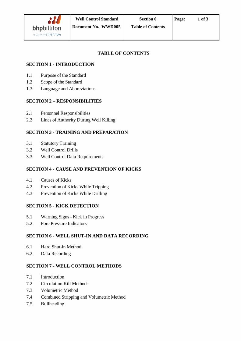
REVISION SUMMARY
Revision Description Issue
2 • Included Performance Standards for Well Control system testing • Included Performance Standards for DP Well Control System BOP stack
configurations • Changed corporate log and deleted unauthorized logos
May 2010
1 • Worldwide Drilling structure & organisation, replacing references to ‘Group Centre’ and ‘Regional’
• Deleted ‘Well Control Policies’ Section 2 – now contained in WWD000 Drilling Policies
• Changes to allowable Kick Tolerance to bring in line with WWD000
September 2006
0 • Original Issue December 1997
Well Control Standard
Document No. WWD005
Section 0
Table of Contents
Page: 1 of 3
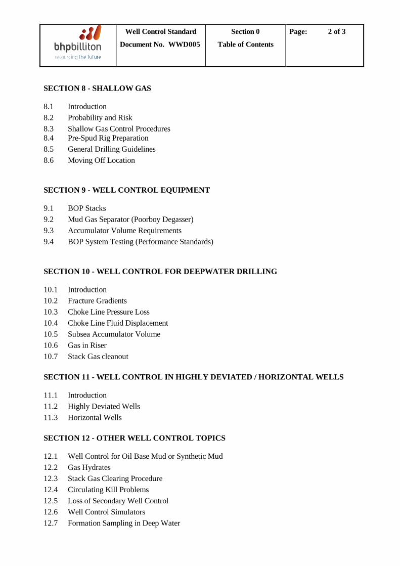
TABLE OF CONTENTS SECTION 1 - INTRODUCTION 1.1 Purpose of the Standard 1.2 Scope of the Standard 1.3 Language and Abbreviations SECTION 2 – RESPONSIBILITIES 2.1 Personnel Responsibilities 2.2 Lines of Authority During Well Killing SECTION 3 - TRAINING AND PREPARATION 3.1 Statutory Training 3.2 Well Control Drills 3.3 Well Control Data Requirements SECTION 4 - CAUSE AND PREVENTION OF KICKS 4.1 Causes of Kicks 4.2 Prevention of Kicks While Tripping 4.3 Prevention of Kicks While Drilling SECTION 5 - KICK DETECTION 5.1 Warning Signs - Kick in Progress 5.2 Pore Pressure Indicators SECTION 6 - WELL SHUT-IN AND DATA RECORDING 6.1 Hard Shut-in Method 6.2 Data Recording SECTION 7 - WELL CONTROL METHODS 7.1 Introduction 7.2 Circulation Kill Methods 7.3 Volumetric Method 7.4 Combined Stripping and Volumetric Method 7.5 Bullheading
Well Control Standard
Document No. WWD005
Section 0
Table of Contents
Page: 2 of 3
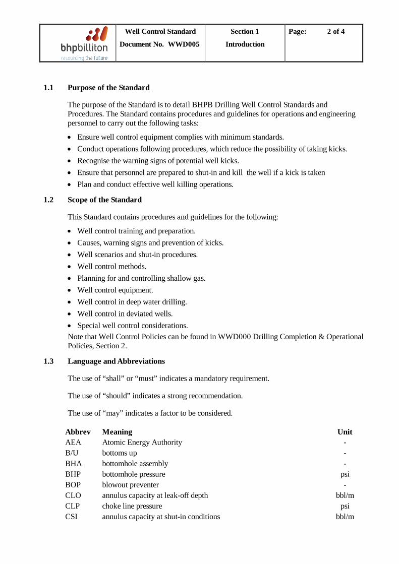
SECTION 8 - SHALLOW GAS 8.1 Introduction 8.2 Probability and Risk 8.3 Shallow Gas Control Procedures 8.4 Pre-Spud Rig Preparation 8.5 General Drilling Guidelines 8.6 Moving Off Location SECTION 9 - WELL CONTROL EQUIPMENT 9.1 BOP Stacks 9.2 Mud Gas Separator (Poorboy Degasser) 9.3 Accumulator Volume Requirements 9.4 BOP System Testing (Performance Standards) SECTION 10 - WELL CONTROL FOR DEEPWATER DRILLING 10.1 Introduction 10.2 Fracture Gradients 10.3 Choke Line Pressure Loss 10.4 Choke Line Fluid Displacement 10.5 Subsea Accumulator Volume 10.6 Gas in Riser 10.7 Stack Gas cleanout SECTION 11 - WELL CONTROL IN HIGHLY DEVIATED / HORIZONTAL WELLS 11.1 Introduction 11.2 Highly Deviated Wells 11.3 Horizontal Wells SECTION 12 - OTHER WELL CONTROL TOPICS 12.1 Well Control for Oil Base Mud or Synthetic Mud 12.2 Gas Hydrates 12.3 Stack Gas Clearing Procedure 12.4 Circulating Kill Problems 12.5 Loss of Secondary Well Control 12.6 Well Control Simulators 12.7 Formation Sampling in Deep Water

Well Control Standard
Document No. WWD005
Section 0
Table of Contents
Page: 3 of 3
APPENDICES - WELL CONTROL EXAMPLE CALCULATIONS APPENDIX 1 - CONVENTIONAL KILL - WAIT AND WEIGHT
APPENDIX 2 - WELL CONTROL EXAMPLE: COMBINED STRIPPING AND
VOLUMETRIC KILL
APPENDIX 3 - SUMMARY OF UK HSE NOTICE 11/90
APPENDIX 4 - WELL CONTROL STANDARD OPERATING PROCEDURES

Well Control Standard
Document No. WWD005
Section 1
Introduction
Page: 1 of 4
TABLE OF CONTENTS
1.1 Purpose of the Standard ...........................................................................................................2 1.2 Scope of the Standard................................................................................................................2 1.3 Language and Abbreviations....................................................................................................2
Well Control Standard
Document No. WWD005
Section 1
Introduction
Page: 2 of 4
1.1 Purpose of the Standard
The purpose of the Standard is to detail BHPB Drilling Well Control Standards and Procedures. The Standard contains procedures and guidelines for operations and engineering personnel to carry out the following tasks:
• Ensure well control equipment complies with minimum standards. • Conduct operations following procedures, which reduce the possibility of taking kicks. • Recognise the warning signs of potential well kicks. • Ensure that personnel are prepared to shut-in and kill the well if a kick is taken • Plan and conduct effective well killing operations.
1.2 Scope of the Standard
This Standard contains procedures and guidelines for the following:
• Well control training and preparation. • Causes, warning signs and prevention of kicks. • Well scenarios and shut-in procedures. • Well control methods. • Planning for and controlling shallow gas. • Well control equipment. • Well control in deep water drilling. • Well control in deviated wells. • Special well control considerations. Note that Well Control Policies can be found in WWD000 Drilling Completion & Operational Policies, Section 2.
1.3 Language and Abbreviations
The use of “shall” or “must” indicates a mandatory requirement.
The use of “should” indicates a strong recommendation.
The use of “may” indicates a factor to be considered.
Abbrev Meaning Unit AEA Atomic Energy Authority - B/U bottoms up - BHA bottomhole assembly - BHP bottomhole pressure psi BOP blowout preventer - CLO annulus capacity at leak-off depth bbl/m CLP choke line pressure psi CSI annulus capacity at shut-in conditions bbl/m
Well Control Standard
Document No. WWD005
Section 1
Introduction
Page: 3 of 4
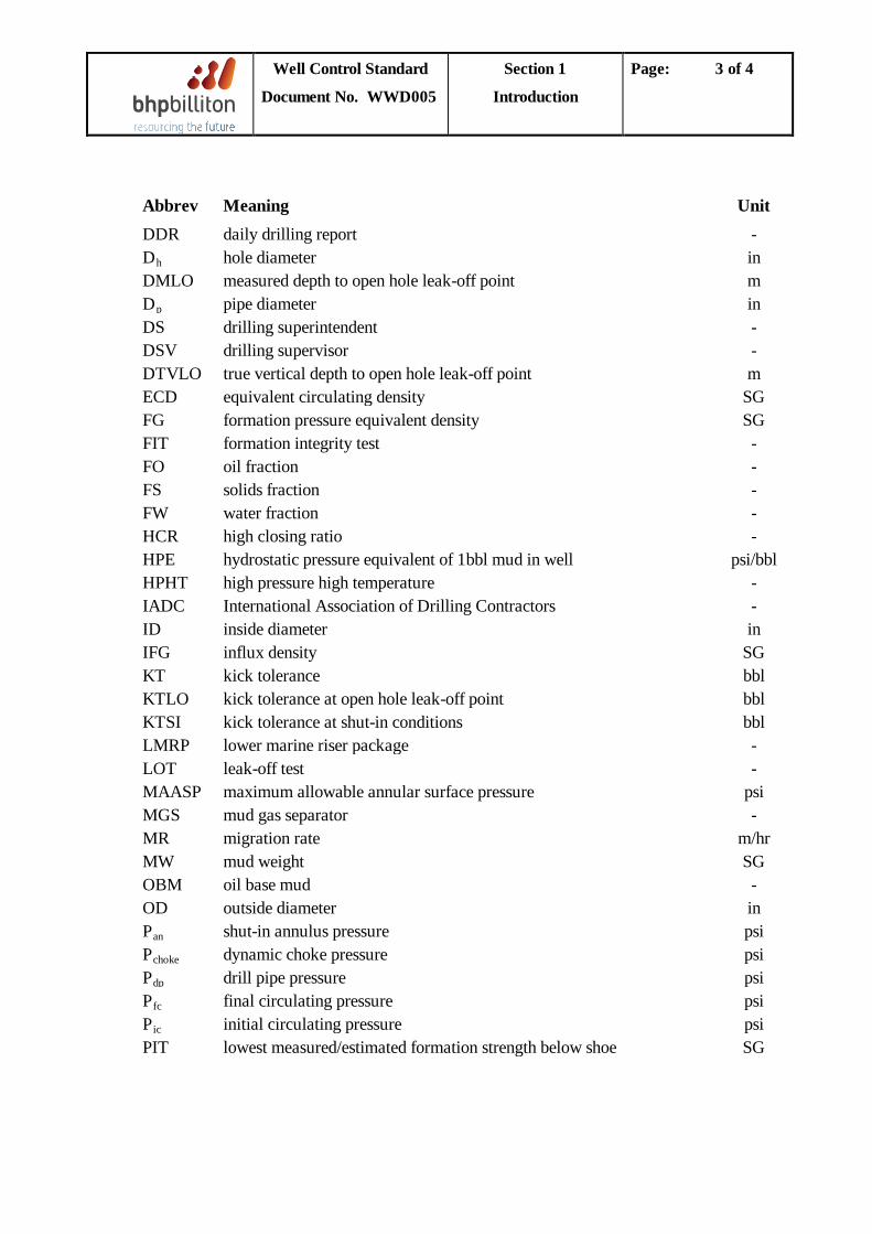
Abbrev Meaning Unit DDR daily drilling report - D hole diameter h in DMLO measured depth to open hole leak-off point m D pipe diameter p in DS drilling superintendent - DSV drilling supervisor - DTVLO true vertical depth to open hole leak-off point m ECD equivalent circulating density SG FG formation pressure equivalent density SG FIT formation integrity test - FO oil fraction - FS solids fraction - FW water fraction - HCR high closing ratio - HPE hydrostatic pressure equivalent of 1bbl mud in well psi/bbl HPHT high pressure high temperature - IADC International Association of Drilling Contractors - ID inside diameter in IFG influx density SG KT kick tolerance bbl KTLO kick tolerance at open hole leak-off point bbl KTSI kick tolerance at shut-in conditions bbl LMRP lower marine riser package - LOT leak-off test - MAASP maximum allowable annular surface pressure psi MGS mud gas separator - MR migration rate m/hr MW mud weight SG OBM oil base mud - OD outside diameter in P shut-in annulus pressure an psi P dynamic choke pressure choke psi P drill pipe pressure dp psi P final circulating pressure fc psi P initial circulating pressure ic psi PIT lowest measured/estimated formation strength below shoe SG

Well Control Standard
Document No. WWD005
Section 1
Introduction
Page: 4 of 4
Abbrev Meaning Unit PMAX maximum allowable downhole pressure at open hole weak point psi POB personnel on board - POOH pull out of hole - PWD Pressure While Drilling (tools) - SCR slow circulating rate SPM SF safety factor - SICP shut-in casing pressure psi SIDPP shut-in drill pipe pressure psi SPM strokes per minute - TDS top drive system - W&W wait and weight well kill method - WBM water base mud -

Well Control Standard
Document No. WWD005
Section 2
Responsibilities
Page: 1 of 6
TABLE OF CONTENTS
2.1 Personnel Responsibilities ......................................................................................................2
2.2 Lines of Authority During Well Killing .................................................................................4
Well Control Standard
Document No. WWD005
Section 2
Responsibilities
Page: 2 of 6
2.1 Personnel Responsibilities
Primary Well Control must be maintained at all times. In the event that Secondary Control becomes necessary, the well must be brought back under control as safely as possible.
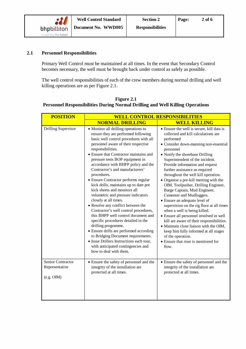
The well control responsibilities of each of the crew members during normal drilling and well killing operations are as per Figure 2.1.
Figure 2.1 Personnel Responsibilities During Normal Drilling and Well Killing Operations
POSITION WELL CONTROL RESPONSIBILITIES
NORMAL DRILLING WELL KILLING Drilling Supervisor
• Monitor all drilling operations to ensure they are performed following basic well control procedures with all personnel aware of their respective responsibilities.
• Ensure that Contractor maintains and pressure tests BOP equipment in accordance with BHPP policy and the Contractor’s and manufacturers’ procedures.
• Ensure Contractor performs regular kick drills, maintains up to date pre kick sheets and monitors all volumetric and pressure indicators closely at all times.
• Resolve any conflict between the Contractor’s well control procedures, this BHPP well control document and specific procedures detailed in the drilling programme.
• Ensure drills are performed according to Bridging Document requirements.
• Issue Drillers Instructions each tour, with anticipated contingencies and how to deal with them.
• Ensure the well is secure, kill data is collected and kill calculations are performed
• Consider down-manning non-essential personnel
• Notify the shorebase Drilling Superintendent of the incident. Provide information and request further assistance as required throughout the well kill operation.
• Organise a pre-kill meeting with the OIM, Toolpusher, Drilling Engineer, Barge Captain, Mud Engineer, Cementer and Mudloggers.
• Ensure an adequate level of supervision on the rig floor at all times when a well is being killed.
• Ensure all personnel involved in well kill are aware of their responsibilities.
• Maintain close liaison with the OIM, keep him fully informed at all stages of the operation.
• Ensure that riser is monitored for flow.
Senior Contractor Representative (e.g. OIM)
• Ensure the safety of personnel and the integrity of the installation are protected at all times.
• Ensure the safety of personnel and the integrity of the installation are protected at all times.
Well Control Standard
Document No. WWD005
Section 2
Responsibilities
Page: 3 of 6
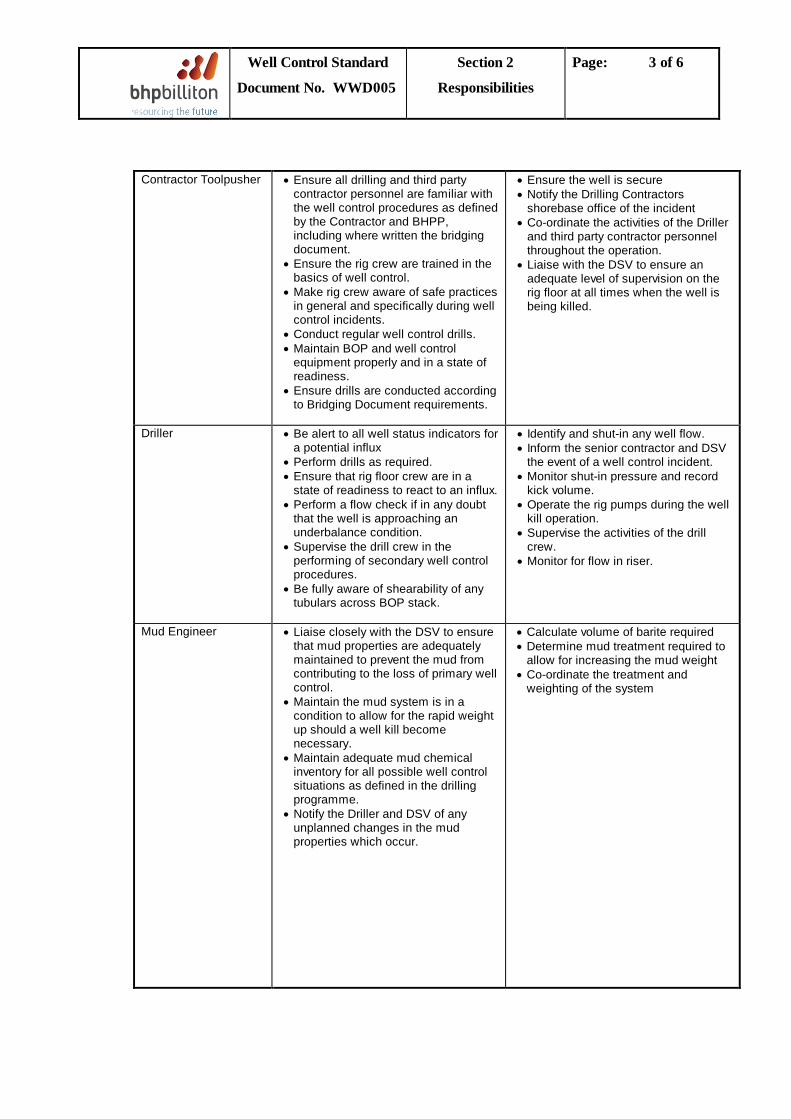
Contractor Toolpusher • Ensure all drilling and third party
contractor personnel are familiar with the well control procedures as defined by the Contractor and BHPP, including where written the bridging document.
• Ensure the rig crew are trained in the basics of well control.
• Make rig crew aware of safe practices in general and specifically during well control incidents.
• Conduct regular well control drills. • Maintain BOP and well control
equipment properly and in a state of readiness.
• Ensure drills are conducted according to Bridging Document requirements.
• Ensure the well is secure • Notify the Drilling Contractors
shorebase office of the incident • Co-ordinate the activities of the Driller
and third party contractor personnel throughout the operation.
• Liaise with the DSV to ensure an adequate level of supervision on the rig floor at all times when the well is being killed.
Driller • Be alert to all well status indicators for a potential influx
• Perform drills as required. • Ensure that rig floor crew are in a
state of readiness to react to an influx. • Perform a flow check if in any doubt
that the well is approaching an underbalance condition.
• Supervise the drill crew in the performing of secondary well control procedures.
• Be fully aware of shearability of any tubulars across BOP stack.
• Identify and shut-in any well flow. • Inform the senior contractor and DSV
the event of a well control incident. • Monitor shut-in pressure and record
kick volume. • Operate the rig pumps during the well
kill operation. • Supervise the activities of the drill
crew. • Monitor for flow in riser.
Mud Engineer • Liaise closely with the DSV to ensure that mud properties are adequately maintained to prevent the mud from contributing to the loss of primary well control.
• Maintain the mud system is in a condition to allow for the rapid weight up should a well kill become necessary.
• Maintain adequate mud chemical inventory for all possible well control situations as defined in the drilling programme.
• Notify the Driller and DSV of any unplanned changes in the mud properties which occur.
• Calculate volume of barite required • Determine mud treatment required to
allow for increasing the mud weight • Co-ordinate the treatment and
weighting of the system
Well Control Standard
Document No. WWD005
Section 2
Responsibilities
Page: 4 of 6
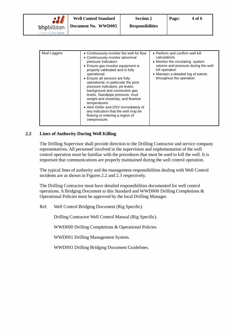
Mud Loggers • Continuously monitor the well for flow
• Continuously monitor abnormal pressure indicators
• Ensure gas monitor equipment is properly calibrated and is fully operational.
• Ensure all sensors are fully operational, in particular the pore pressure indicators, pit levels, background and connection gas levels, Standpipe pressure, mud weight and resistivity, and flowline temperatures.
• Alert Driller and DSV immediately of any indication that the well may be flowing or entering a region of overpressure.
• Perform and confirm well kill calculations
• Monitor the circulating system volume and pressure during the well kill operation
• Maintain a detailed log of events throughout the operation
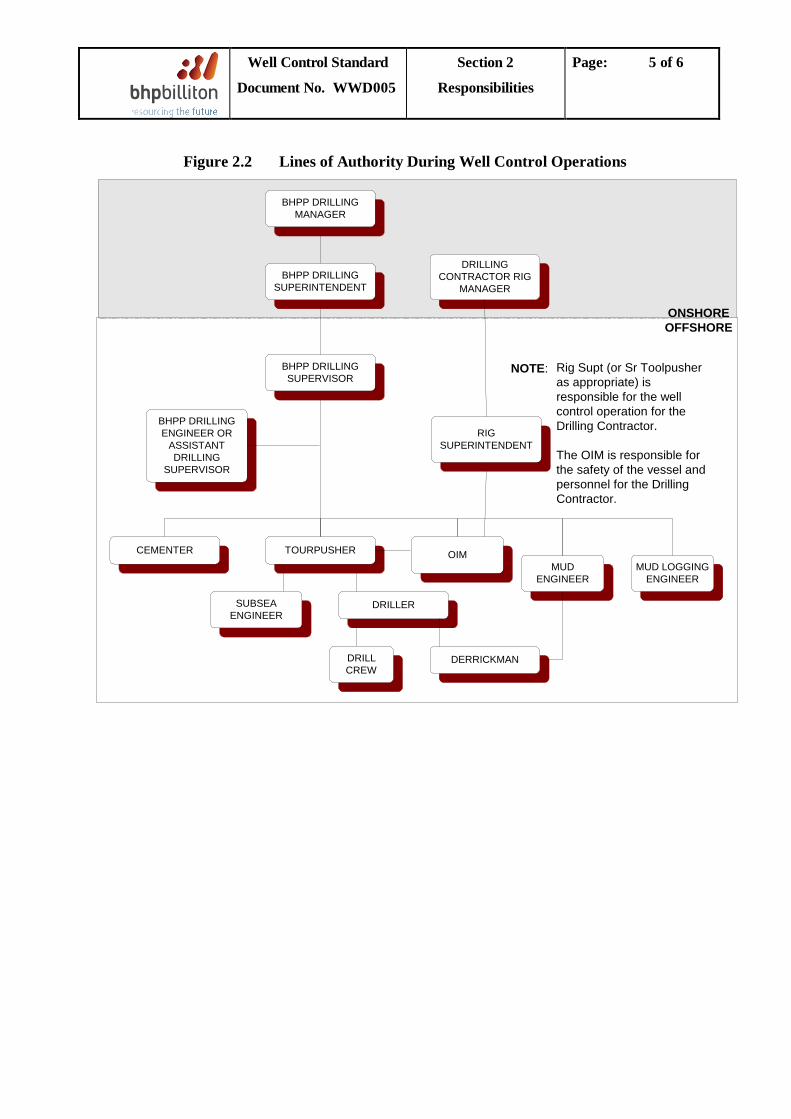
2.2 Lines of Authority During Well Killing
The Drilling Supervisor shall provide direction to the Drilling Contractor and service company representatives. All personnel involved in the supervision and implementation of the well control operation must be familiar with the procedures that must be used to kill the well. It is important that communications are properly maintained during the well control operation.
The typical lines of authority and the management responsibilities dealing with Well Control incidents are as shown in Figures 2.2 and 2.3 respectively.
The Drilling Contractor must have detailed responsibilities documented for well control operations. A Bridging Document to this Standard and WWD000 Drilling Completions & Operational Policies must be approved by the local Drilling Manager.
Ref. Well Control Bridging Document (Rig Specific).
Drilling Contractor Well Control Manual (Rig Specific).
WWD000 Drilling Completions & Operational Policies
WWD001 Drilling Management System.
WWD003 Drilling Bridging Document Guidelines.
Well Control Standard
Document No. WWD005
Section 2
Responsibilities
Page: 5 of 6
Figure 2.2 Lines of Authority During Well Control Operations
BHPP DRILLINGMANAGER
BHPP DRILLINGSUPERINTENDENT
DRILLINGCONTRACTOR RIG
MANAGER
BHPP DRILLINGSUPERVISOR
BHPP DRILLINGENGINEER OR
ASSISTANTDRILLING
SUPERVISOR
CEMENTER TOURPUSHER OIMMUD LOGGING
ENGINEERMUD
ENGINEER
DRILLERSUBSEAENGINEER
DRILLCREW
DERRICKMAN
ONSHOREOFFSHORE
NOTE: Rig Supt (or Sr Toolpusheras appropriate) isresponsible for the wellcontrol operation for theDrilling Contractor.
The OIM is responsible forthe safety of the vessel andpersonnel for the DrillingContractor.
RIGSUPERINTENDENT
Well Control Standard
Document No. WWD005
Section 2
Responsibilities
Page: 6 of 6
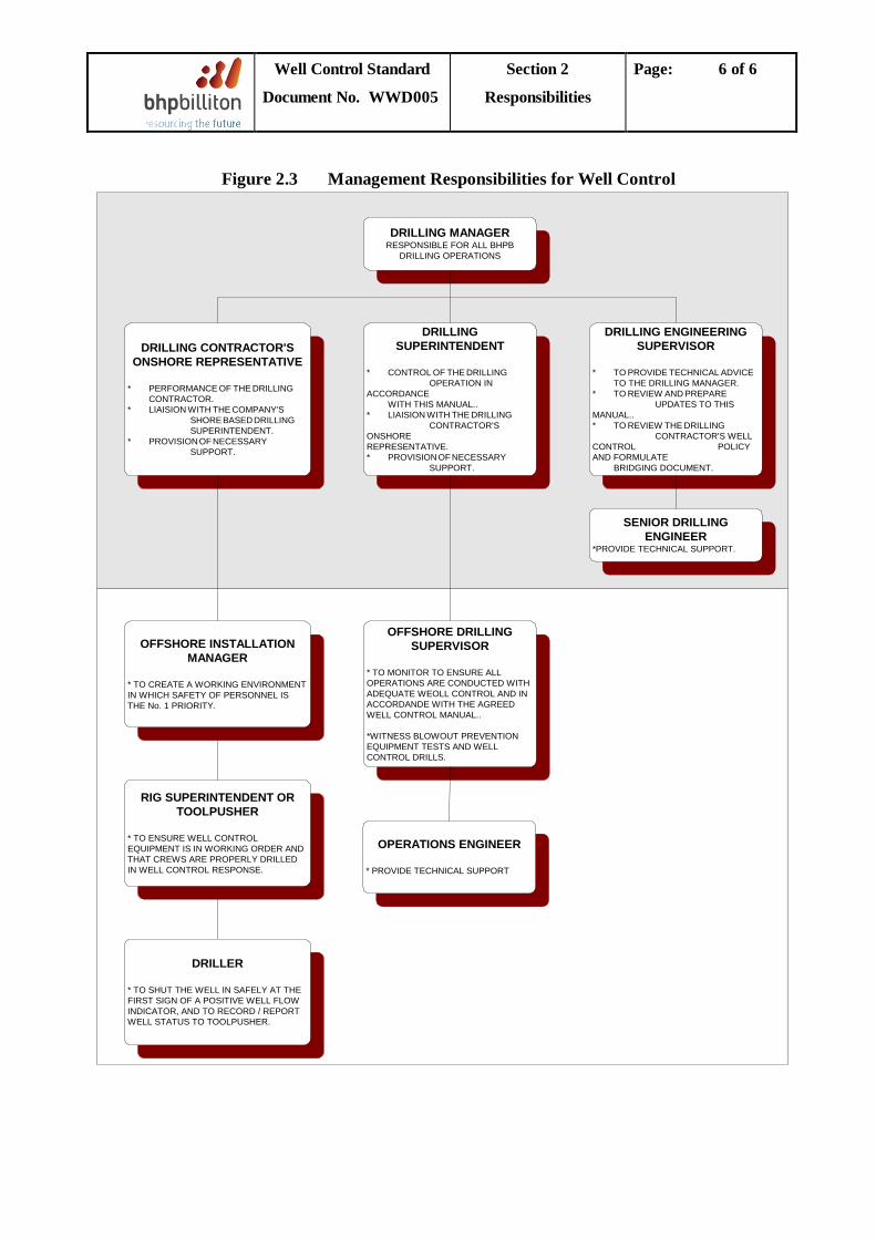
Figure 2.3 Management Responsibilities for Well Control
DRILLING MANAGERRESPONSIBLE FOR ALL BHPB
DRILLING OPERATIONS
DRILLINGSUPERINTENDENT
* CONTROL OF THE DRILLING OPERATION IN
ACCORDANCEWITH THIS MANUAL..
* LIAISION WITH THE DRILLING CONTRACTOR'S
ONSHOREREPRESENTATIVE.* PROVISION OF NECESSARY
SUPPORT.
DRILLING CONTRACTOR'SONSHORE REPRESENTATIVE
* PERFORMANCE OF THE DRILLING CONTRACTOR.
* LIAISION WITH THE COMPANY'S SHORE BASED DRILLING SUPERINTENDENT.
* PROVISION OF NECESSARY SUPPORT.
DRILLING ENGINEERINGSUPERVISOR
* TO PROVIDE TECHNICAL ADVICE TO THE DRILLING MANAGER.
* TO REVIEW AND PREPARE UPDATES TO THIS
MANUAL..* TO REVIEW THE DRILLING
CONTRACTOR'S WELLCONTROL POLICYAND FORMULATE
BRIDGING DOCUMENT.
SENIOR DRILLINGENGINEER
*PROVIDE TECHNICAL SUPPORT.
OFFSHORE INSTALLATIONMANAGER
* TO CREATE A WORKING ENVIRONMENTIN WHICH SAFETY OF PERSONNEL ISTHE No. 1 PRIORITY.
RIG SUPERINTENDENT ORTOOLPUSHER
* TO ENSURE WELL CONTROLEQUIPMENT IS IN WORKING ORDER ANDTHAT CREWS ARE PROPERLY DRILLEDIN WELL CONTROL RESPONSE.
DRILLER
* TO SHUT THE WELL IN SAFELY AT THEFIRST SIGN OF A POSITIVE WELL FLOWINDICATOR, AND TO RECORD / REPORTWELL STATUS TO TOOLPUSHER.
OFFSHORE DRILLINGSUPERVISOR
* TO MONITOR TO ENSURE ALLOPERATIONS ARE CONDUCTED WITHADEQUATE WEOLL CONTROL AND INACCORDANDE WITH THE AGREEDWELL CONTROL MANUAL..
*WITNESS BLOWOUT PREVENTIONEQUIPMENT TESTS AND WELLCONTROL DRILLS.
OPERATIONS ENGINEER
* PROVIDE TECHNICAL SUPPORT
Well Control Standard
Document No. WWD005
Section 3
Training & Preparation
Page: 1 of 14
TABLE OF CONTENTS
3.1 Statutory Training .....................................................................................................................2
3.2 Well Control Drills ....................................................................................................................2
3.2.1 General Requirements ................................................................................................2
3.2.2 Reaction Times .............................................................................................................2
3.2.3 Stripping Drills .............................................................................................................3
3.3 Well Control Data Requirements ............................................................................................4
3.3.1 Slow Circulating Rates (SCR’s) .................................................................................4
3.3.2 Pore Pressure Prediction ............................................................................................4
3.3.3 Fracture Gradient........................................................................................................4
3.3.4 Leak Off Test ................................................................................................................5
3.3.4.1 Leak-Off Test Profiles .....................................................................................5
3.3.4.2 LOT Procedure................................................................................................7
3.3.4.3 Calculation and Interpretation......................................................................9
3.3.5 Maximum Allowable Annular Surface Pressure ................................................... 10
3.3.6 Kick Tolerance .......................................................................................................... 10
3.3.6.1 General .......................................................................................................... 10
3.3.6.2 Calculation ..................................................................................................... 11
3.3.6.3 Kick Tolerance Levels .................................................................................. 11
3.3.7 Equivalent Circulating Density............................................................................... 13
3.3.8 Pre Kick Sheet ........................................................................................................... 13
Well Control Standard
Document No. WWD005
Section 3
Training & Preparation
Page: 2 of 14
3.1 Statutory Training
All key personnel must hold a recognised well control certificate equivalent to IWCF or MMS (IADC Well CAP). Renewal is required at no more than two yearly intervals. These personnel shall include:
• Drilling Supervisor • Senior Contractor Representative • Contractor Toolpushers / Tourpushers • Drillers • Assistant Drillers • Derrickmen • Mud Engineers • Mud Loggers
3.2 Well Control Drills
3.2.1 General Requirements a) Well control drills shall be initiated by and performed under the supervision of the DSV to
ensure that the crews are adequately trained and prepared to implement well control procedures correctly. They must be performed in compliance with the Bridging Document.
b) Well control drills shall only be conducted when they do not complicate ongoing operations. A kick should be simulated by manipulation of a primary kick indicator such as the tank level indicator or the flow line indicator.
c) It may be necessary to repeat the drills each tour until the DSV is satisfied that the crews are adequately trained and responsive. Thereafter, in order to maintain their alertness and competence, the frequency of the drills can be reduced.
d) Trip drills should only be conducted if the BHA is inside the casing shoe. e) Out-of-hole drills may be conducted at any time when out of hole with no tools or wireline
through the BOP stack. f) Diverter drills should be conducted prior to drilling out the surface casing shoe, and daily
thereafter for each crew whenever Standing Instructions are to divert. g) Stripping drills should be conducted once per well for each crew, prior to drilling out a
casing shoe.
3.2.2 Reaction Times
The following shall be recorded in the IADC tour report and the DDR:
• The types of drill conducted and the reaction time from the moment the kick is simulated until the crew is ready to start the closing procedure.
• The total time taken complete the drill.
The DSV shall then be in a position to judge the performance of the crew and equipment. Recommendations for improving the performance should be discussed with the crews.
Well Control Standard
Document No. WWD005
Section 3
Training & Preparation
Page: 3 of 14
3.2.3 Stripping Drills
Stripping drills should be held with the drill pipe in the casing, before drilling out the shoe. The following procedure is recommended:
1. Install and close Kelly cock. 2. Install Gray valve, open Kelly cock. 3. Open Choke line valve (HCR), close annular preventer. 4. Close Choke line valve behind choke. 5. Pressure up annulus to 500 psi via kill line. 6. Reduce operating pressure of the annular preventer to a minimum, whilst avoiding preventer
leakage. 7. Open ball valve to the surge bottle, (If using a Cameron D-preventer remove Vent plug on
opening side). 8. Line up choke manifold to the trip and stripping tank. 9. Empty trip tank to 30% (to enable proper measurements). 10.Pick up and make up stand of drill pipe, grease tool joint upset, (bottom side), remove tong
die marks and all drill pipe/casing protectors. 11.Strip in, keep Pch at Pan
12.When the Stand is stripped in, close the choke at P = 500 psi.
an
13.Drain the closed end displacement of the stand from the trip tank into a calibrated stripping tank (if available).
= 500 psi.
14.Check the trip tank for volume gain. 15.Run another 1 to 2 stands. 16.End of stripping drill, (If using a Cameron D-preventer, install vent plug). 17.Bleed off Pan
18.Open annular preventer, close HCR.
= 0, close surge bottle ball valve, increase annular preventer working pressure to normal.
19.Pull stripped-in stands, close Kelly cock, remove Gray valve, open Kelly cock and remove same.
Notes:
• Prepare for and fill up stands with original mud. • Check for trapped pressures under Gray valve and Kelly cock before removal. • To avoid risk of cross threading the vent plug by the Cameron D, the Weco union of the
opening line can be loosened.
Well Control Standard
Document No. WWD005
Section 3
Training & Preparation
Page: 4 of 14
3.3 Well Control Data Requirements
Basic well data must be recorded accurately at regular intervals and be easily available. The quality of this pre-recorded data may determine the success of well control operations.
3.3.1 Slow Circulating Rates (SCR’s)
SCR pressures should be taken once per tour and upon changes in mud weight and recorded on the IADC report and on the DDR.
A minimum of two pump rates shall be taken. The SCR’s chosen should not be less than 0.5 bbl/min and not greater than 4 bbl/min. The pressures must be recorded using the gauge to be used during well kill operations.
Notes:
• Choke line pressure (CLP) loss on floaters should be calculated by comparing circulation pressure via the riser, and via the choke line. CLP is the difference between the two pressures minus any choke backpressure. Where CLP is high, it should be measured by pumping down the choke line to prevent subjecting the formation to unnecessary additional pressure.
• In general the SCR pressure will be confirmed just prior to circulating out a kick when the pumps are brought up to speed by the constant casing pressure method.
• On many floating rigs, stack mounted choke and kill gauges can be used to monitor pressure at the wellhead and can therefore be used for constant pressure start-up.
3.3.2 Pore Pressure Prediction
A pore pressure estimate is required to allow calculation of kick tolerance (see Section 3.3.6). This should be generated by the mud logger using indicators such as background and connection gas levels, shale density and mud properties (see Section 5.2).
This is normally generated by the BHP Billiton Geological Operations Group and / or Well Project team. On the rig, the mud loggers must monitor the well for all pore pressure indicators as directed by the Drilling Supervisor.
3.3.3 Fracture Gradient
The formation fracture pressure is the pressure at the formation required to initiate a fracture and allow whole mud to be pumped in to it. It is the sum of the rock matrix stress and the pore pressure within it. Formation fracture pressures should be expressed as an equivalent mud weight.
The fracture gradient prediction shall be provided in the Drilling Programme. It must be updated by the mud logger for inclusion on the well log by the Senior Drilling Engineer and maintained on the rig by the Mud Loggers.
Well Control Standard
Document No. WWD005
Section 3
Training & Preparation
Page: 5 of 14
3.3.4 Leak Off Test
LOT’s should be conducted in accordance with the Drilling Programme. They may be required at any of the following times:
• After drilling out every casing shoe after the BOP stack is run. • Prior to drilling a suspected or known overpressure zone. • After drilling a suspected weak formation.
The leak-off value shall be used to establish the MAASP for well control procedures, and to calculate Kick Tolerance for determining maximum casing setting depth.
LOT data must be plotted on a graph of Applied Surface Pressure versus Volume Pumped to determine the surface leak-off pressure. The formation fracture pressure for a given depth is calculated as the sum of the mud hydrostatic pressure and the applied surface pressure at leak-off.
3.3.4.1 Leak-Off Test Profiles
It is important to understand the behaviour of different types of rock during the LOT because this will affect the way in which the test is conducted.
A soft recent sediment behaves plastically as shown in Figure 3.1 with no definite deviation from the trend to indicate the leak-off pressure. In such a case the leak-off pressure is a subjective value, and there is little danger in exceeding this pressure in order to justify the point chosen.
Conversely, an older sediment like the consolidated impermeable formation in Figure 3.1 will show a marked departure from the trend and if pumping is continued past the leak-off pressure, the formation breakdown pressure may be exceeded. This may result in a new leak-off pressure considerably lower than if the LOT had been halted at initial leak-off, causing mud losses or significant reduction in the maximum allowable mud weight for the section.

Well Control Standard
Document No. WWD005
Section 3
Training & Preparation
Page: 6 of 14
Figure 3.1 LOT Profiles
BLEED OFF
FCPISIP
FPP
FBP
LEAKOFF
PRESSURES
CONTINUOUSINJECTIONPERIOD
SHUT INPERIOD
1
PRES
SURE
CUMULATIVE VOLUME
UNCONSOLIDATED PLASTIC FORMATION (SOFT RECENT SEDIMENT)
PRES
SURE
CUMULATIVE VOLUME
CONSOLIDATED FORMATIONSLOW PERMEABILIY OR IMPERMEABLE
1
PRES
SURE
CUMULATIVE VOLUME
CONSOLIDATED FORMATIONS“LIMIT TEST”
DESIREDTESTPRESSURE
GENERAL SCHEMATIC OF EXTENDED LOT
1
FINAL PUMP PRESSURE AFTER EACH INCREMENT
FINAL PRESSURE AFTER WAITING PERIOD
LEAK-OFF PRESSURE
LOT Profiles
Leak-off Pressure (LOP) : The pressure fluid starts leaking off into the formation or through the casing cementation. Formation Breakdown Pressure (FBP) : The pressure a fracture is initiated in the formation. Fracture Propagation Pressure (FPP) : The pressure required to propagate fluid further into the formation. Instantaneous Shut in Pressure (ISIP) : At the moment the pumps are shut in there is an almost instantaneous pressure drop once injection
stops. The ISIP is the pressure level after this drop. Fracture Closure Pressure (FCP) : The fluid pressure at which the fracture width reduces to zero. It is a slope inflection point below the
ISIP. A relationship between FCP, depth (TVDSS) and pore pressure has been developed which appear to be applicable field wide.
Well Control Standard
Document No. WWD005
Section 3
Training & Preparation
Page: 7 of 14
3.3.4.2 LOT Procedure
The following procedure should be followed:
1. Drill out casing shoe and drill 3 meters (10 feet) of new formation. 2. Circulate to ensure mud column is balanced and cuttings are circulated out. 3. Assess the formation type and anticipate the most probable leak-off profile. 4. Pull bit inside casing shoe. If a slug has been pumped, ensure it is circulated out. 5. Hang off the drillstring on the designated pipe rams (floating rig). 6. Pump down the drillpipe at a constant rate with the cement unit. Suggested pump rate
should be less than 0.5 bpm. 7. Record the applied pressure at small incremental volumes of mud pumped. It is suggested
that 0.25 bbl increments be recorded and plotted, in order to determine when the leak-off value has been reached and pumping should stop [plot pressure (psi) versus barrels (bbls) pumped during the test].
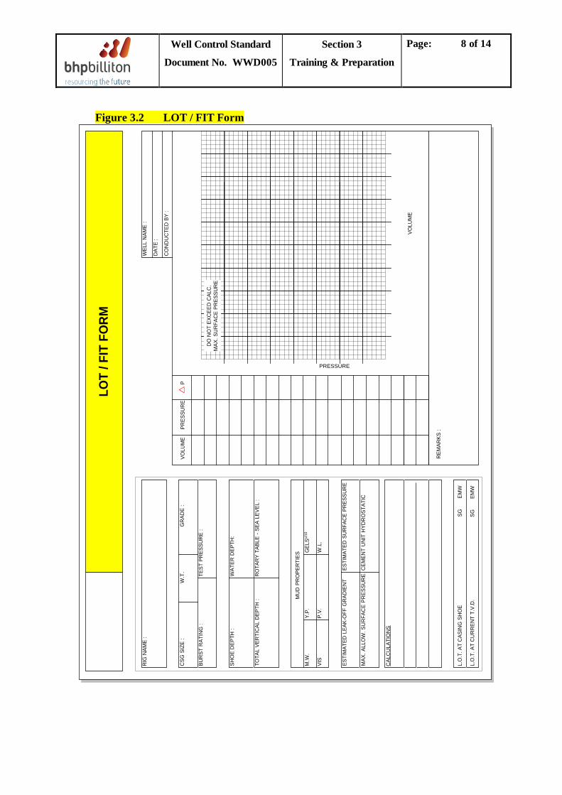
8. The LOT/FIT Form (Figure 3.2, or other as approved by the Drilling Superintendent) shall be prepared prior to conducting the test, with the estimated surface applied leak-off pressure and maximum applied surface pressure plotted on the graph.
9. For a LOT, stop pumping when leak-off is judged to have occurred based on the LOT profile anticipated in Step 3. For a FIT, stop pumping when the preset maximum required surface pressure is reached, or the formation leak-off is reached, whichever occurs first. Record and plot the pressures in one-minute intervals after shutting down the pump until the pressure stabilises.
10.Bleed off the pressure and record the volume of fluid recovered. Any difference between the volume bled back and the volume pumped is volume that has been lost to the hole.
Note: Where a Pressure While Drilling tool is in the BHA, it is advisable to “pump up” LOT data to validate / calibrate the surface LOT/FIT data. When the Pressure While Drilling tool is recovered to surface, the memory data should be recovered to provide a downhole full form LOT / FIT.
Well Control Standard
Document No. WWD005
Section 3
Training & Preparation
Page: 8 of 14
Figure 3.2 LOT / FIT Form LO
T / F
IT F
ORM
WEL
L N
AME
:
DAT
E :
CO
ND
UC
TED
BY
:
RIG
NAM
E :
CSG
SIZ
E :
W.T
.G
RAD
E :
BU
RST
RAT
ING
: T
EST
PRES
SUR
E :
SH
OE
DEP
TH :
WAT
ER D
EPTH
:
TO
TAL
VER
TIC
AL D
EPTH
: R
OTA
RY
TABL
E - S
EA L
EVEL
:
MU
D P
RO
PER
TIES
M.W
. Y
.P.
GEL
Su/10
VIS
P.V
. W
.L.
EST
IMAT
ED L
EAK-
OFF
GR
ADIE
NT
EST
IMAT
ED S
UR
FAC
E PR
ESSU
RE
MAX
. ALL
OW
. SU
RFA
CE
PRES
SUR
E C
EMEN
T U
NIT
HYD
RO
STAT
IC
CAL
CU
LATI
ON
S
L.O
.T. A
T C
ASIN
G S
HO
E
SG
E
MW
L.O
.T. A
T C
UR
REN
T T.
V.D
.
SG
EM
W
PRESSURE
VOLU
ME
VOLU
ME
PRES
SUR
EP
R
EMAR
KS :
DO
NO
T EX
CEE
D C
ALC
.M
AX. S
UR
FAC
E PR
ESSU
RE
Well Control Standard
Document No. WWD005
Section 3
Training & Preparation
Page: 9 of 14
3.3.4.3 Calculation and Interpretation
The leak-off pressure gradient shall be calculated as follows:
LOT = PS 1.421 D
+ MW
Where: LOT = maximum equivalent mud weight (SG) PS = applied surface pressure at leak-off (psi) D = depth of suspected leak-off (m) MW = mud weight (SG) OR LOT = PS 0.052 D
+ MW
Where: LOT = maximum equivalent mud weight (ppg) PS = applied surface pressure at leak-off (psi) D = depth of suspected leak-off (ft) MW = mud weight (ppg)
The depth used in this calculation should either be:
• The true vertical depth of the casing shoe. • The true vertical depth of the suspected weakest formation in the open hole section.
The applied surface pressure used shall be the pressure at the identified leak-off point (or the final stabilised pressure, in the case of a FIT). This pressure should be corrected for the mud hydrostatic pressure from the rig floor to the cement unit and for frictional pressure loss at the pump rate used. This is important in situations where there is limited kick tolerance and accurate leak-off values are required. Note that where there is a Pressure While Drilling tool in use, the Drilling Supervisor should set a hard line ECD limit based on the measured downhole LOT/FIT to avoid breaking the shoe.
The shape of the Pressure vs. Volume plot should be analysed to ensure that an accurate leak-off value has been obtained and that the integrity of the casing shoe cement job is satisfactory. The following guidelines shall assist in determining if the leak-off value is valid.
a. A cement channel is indicated if the leak-off pressure is significantly lower than expected, if the pressure versus volume plot has two slopes or if the shut-in shows a continual decline in pressure:
• The low leak-off pressure is due to a large channel allowing communication up hole to a weaker formation.
• The two-slope behaviour is due to a small channel, which restricts fluid flow sufficiently to allow the pressure to increase to leak-off below the shoe after leak-off has already occurred up hole via the channel.
Well Control Standard
Document No. WWD005
Section 3
Training & Preparation
Page: 10 of 14
b. The existence of a plastic zone in the near wellbore region due to drilling damage can result in a fracture being initiated in the formation at a low pressure. If pumping is continued, the pressure can be increased to a higher value until fracture is initiated in the elastic zone further away from the wellbore.
c. A penetrating type of fluid, i.e. water should produce a lower leak-off pressure than should a non-penetrating fluids, e.g. mud.
d. Leak-off tests should always be repeated where results differ from expected.
3.3.5 Maximum Allowable Annular Surface Pressure
The mud hydrostatic head must not exceed the formation strength at any time. In practice the only known formation strength may be at the casing shoe, where a leak-off test was taken. During well control operations, the maximum allowable pressure at the casing shoe is considered to be the critical factor. This pressure is referred to at the surface as MAASP. MAASP equals the formation fracture strength at the shoe minus the hydrostatic head of the mud and/or influx in the casing. When the hydrostatic head of the mud changes, the value of MAASP must be revised.
When an influx enters the casing shoe, the hydrostatic head in the casing decreases and the surface pressure increases. Because of this, the pressure at the choke may be allowed to exceed the original MAASP to maintain bottom hole pressure.
MAASP = (Equiv. Max. MW (SG) - Current MW (SG)) x (Dshoe - TVD)(m) x 1.421
OR
MAASP = (Equiv. Max. MW (ppg) - Current MW (ppg)) x (Dshoe - TVD)(ft) x 0.052
3.3.6 Kick Tolerance
3.3.6.1 General
Kick tolerance is defined as the maximum influx volume that can be circulated past the casing shoe without exceeding the formation strength at the shoe. It is expressed in bbls. Kick tolerance is a design tool used to determine the minimum shoe strength required to reach a predetermined section TD or conversely the maximum drilling depth for a given shoe strength.
Well Control Standard
Document No. WWD005
Section 3
Training & Preparation
Page: 11 of 14
3.3.6.2 Calculation
The preliminary basis for design requires a kick volume tolerance based upon hole size, and in accordance with Table 3.1 of WWD000 Worldwide Drilling Policies, although a smaller margin is permissible if mitigating conditions apply and subject to approval by the Drilling Manager. The Drilling Programme must highlight the required shoe strength for the relevant kick volume tolerance. During the course of a well it is not normally necessary to recalculate the kick tolerance though under some circumstances it will be required. Such circumstances might be:
a) Actual leak-off is less than anticipated. b) Section TD is deeper than originally programmed. c) Mud weight used is greater than originally programmed.
Some of the issues that should be considered when determining allowable influx volume, and the calculation method to be used, are shown in WWD006 Well Design Standard, Sections 2.5.3 and 2.5.4.
3.3.6.3 Kick Tolerance Levels
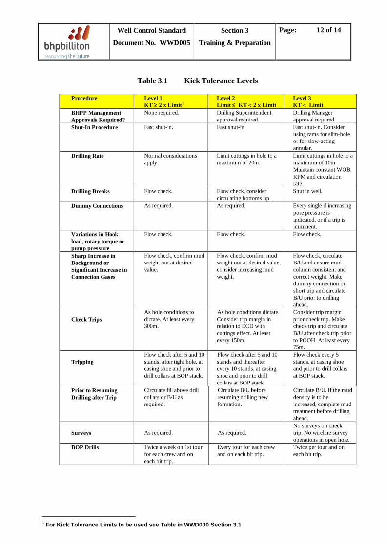
Kick tolerance levels (see Table 3.1) shall be used to provide a method of establishing the procedures to be followed in order to limit the severity of a kick.
Well Control Standard
Document No. WWD005
Section 3
Training & Preparation
Page: 12 of 14
Table 3.1 Kick Tolerance Levels
Procedure Level 1 KT ≥ 2 x Limit1
Level 2 Limit ≤ KT < 2 x Limit
Level 3 KT < Limit
BHPP Management Approvals Required?
None required. Drilling Superintendent approval required.
Drilling Manager approval required.
Shut-In Procedure Fast shut-in. Fast shut-in Fast shut-in. Consider using rams for slim-hole or for slow-acting annular.
Drilling Rate Normal considerations apply.
Limit cuttings in hole to a maximum of 20m.
Limit cuttings in hole to a maximum of 10m. Maintain constant WOB, RPM and circulation rate.
Drilling Breaks Flow check. Flow check, consider circulating bottoms up.
Shut in well.
Dummy Connections As required. As required. Every single if increasing pore pressure is indicated, or if a trip is imminent.
Variations in Hook load, rotary torque or pump pressure
Flow check. Flow check. Flow check.
Sharp Increase in Background or Significant Increase in Connection Gases
Flow check, confirm mud weight out at desired value.
Flow check, confirm mud weight out at desired value, consider increasing mud weight.
Flow check, circulate B/U and ensure mud column consistent and correct weight. Make dummy connection or short trip and circulate B/U prior to drilling ahead.
Check Trips
As hole conditions to dictate. At least every 300m.
As hole conditions dictate. Consider trip margin in relation to ECD with cuttings effect. At least every 150m.
Consider trip margin prior check trip. Make check trip and circulate B/U after check trip prior to POOH. At least every 75m.
Tripping
Flow check after 5 and 10 stands, after tight hole, at casing shoe and prior to drill collars at BOP stack.
Flow check after 5 and 10 stands and thereafter every 10 stands, at casing shoe and prior to drill collars at BOP stack.
Flow check every 5 stands, at casing shoe and prior to drill collars at BOP stack.
Prior to Resuming Drilling after Trip
Circulate fill above drill collars or B/U as required.
Circulate B/U before resuming drilling new formation.
Circulate B/U. If the mud density is to be increased, complete mud treatment before drilling ahead.
Surveys
As required.
As required.
No surveys on check trip. No wireline survey operations in open hole.
BOP Drills Twice a week on 1st tour for each crew and on each bit trip.
Every tour for each crew and on each bit trip.
Twice per tour and on each bit trip.
1 For Kick Tolerance Limits to be used see Table in WWD000 Section 3.1
Well Control Standard
Document No. WWD005
Section 3
Training & Preparation
Page: 13 of 14
3.3.7 Equivalent Circulating Density
The ECD is important when the pressure margins between pore pressure, mud weight and fracture gradient are small. The daily mud and DDR should show the current estimate for the ECD in ppg. The most appropriate fluid behaviour law for the type of fluid in use should be used in the calculation. Where Pressure While Drilling tools are in use, the Drilling Supervisor must set a “hard line” for maximum ECD, based on the downhole LOT/FIT, which shall be agreed and approved by the Drilling Superintendent.
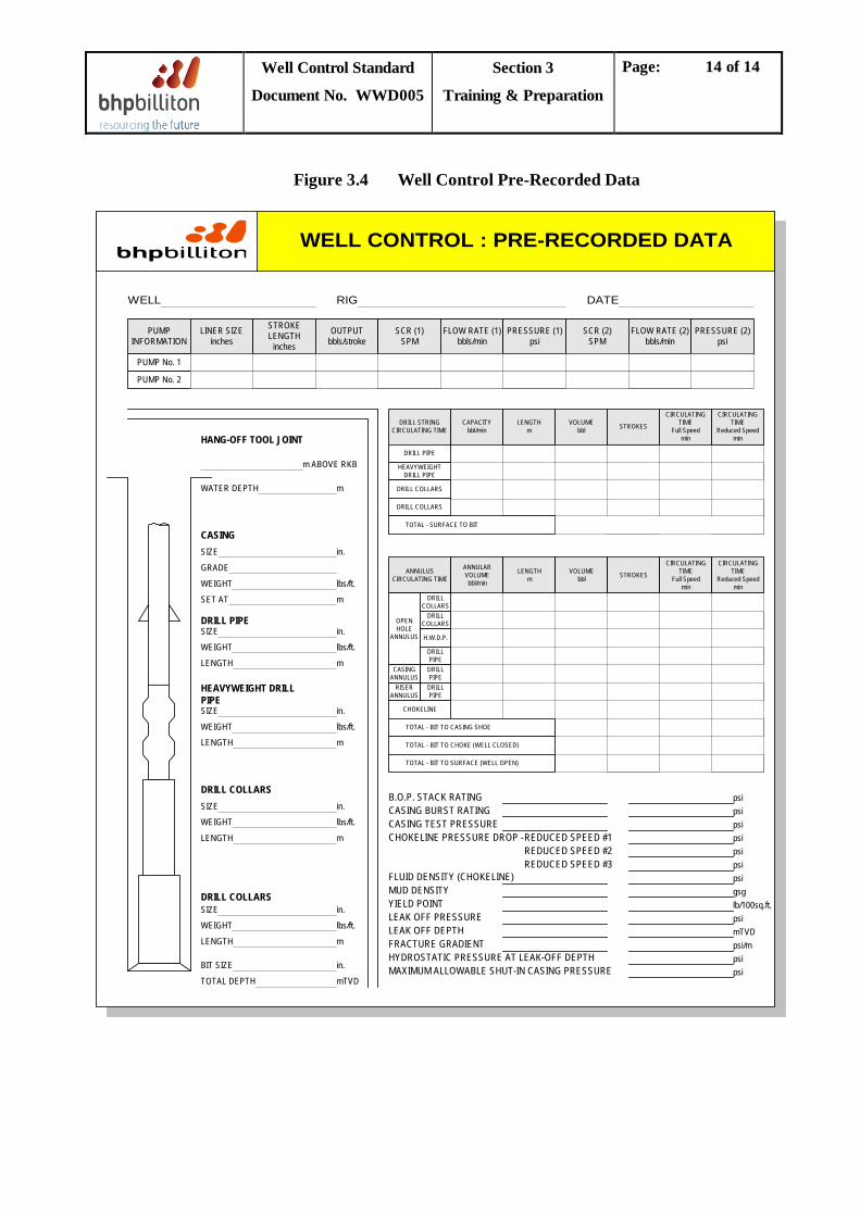
3.3.8 Pre Kick Sheet
A pre kick sheet shall be completed and updated every 24 hours or 300 metres (1000ft) drilled, and when mud weight changes, for all bit runs, to ensure the basic well data is readily available in the event of a kick. (Figure 3.4)
Well Control Standard
Document No. WWD005
Section 3
Training & Preparation
Page: 14 of 14
Figure 3.4 Well Control Pre-Recorded Data
ANNULUSCIRCULATING TIME
OPENHOLE
ANNULUS
DRILLCOLLARS
DRILLCOLLARS
H.W.D.P.
DRILLPIPE
DRILLPIPE
DRILLPIPE
RISERANNULUS
CASINGANNULUS
ANNULARVOLUMEbbl/min
LENGTHm
VOLUMEbbl STROKES
CIRCULATINGTIME
Full Speedmin
CIRCULATINGTIME
Reduced Speedmin
CHOKELINE
TOTAL - BIT TO CASING SHOE
TOTAL - BIT TO CHOKE (WELL CLOSED)
TOTAL - BIT TO SURFACE (WELL OPEN)
DRILL STRINGCIRCULATING TIME
DRILL PIPE
HEAVYWEIGHTDRILL PIPE
DRILL COLLARS
DRILL COLLARS
CAPACITYbbl/min
LENGTHm
VOLUMEbbl STROKES
CIRCULATINGTIME
Full Speedmin
CIRCULATINGTIME
Reduced Speedmin
TOTAL - SURFACE TO BIT
PUMPINFORMATION
LINER SIZEinches
STROKELENGTH
inches
OUTPUTbbls/stroke
SCR (1)SPM
FLOW RATE (1)bbls/min
PRESSURE (1)psi
SCR (2)SPM
FLOW RATE (2)bbls/min
PRESSURE (2)psi
PUMP No. 1
PUMP No. 2
WELL RIG DATE
B.O.P. STACK RATINGCASING BURST RATINGCASING TEST PRESSURECHOKELINE PRESSURE DROP -REDUCED SPEED #1
REDUCED SPEED #2REDUCED SPEED #3
FLUID DENSITY (CHOKELINE)MUD DENSITYYIELD POINTLEAK OFF PRESSURELEAK OFF DEPTHFRACTURE GRADIENTHYDROSTATIC PRESSURE AT LEAK-OFF DEPTHMAXIMUM ALLOWABLE SHUT-IN CASING PRESSURE
psipsipsipsipsipsipsigsglb/100sq.ft.psimTVDpsi/mpsipsi
m ABOVE RKB
WATER DEPTH
SIZE
GRADE
WEIGHT
SET AT
SIZE
WEIGHT
LENGTH
SIZE
WEIGHT
LENGTH
SIZE
WEIGHT
LENGTH
SIZE
WEIGHT
LENGTH
BIT SIZE
TOTAL DEPTH mTVD
in.
m
lbs/ft.
in.
m
lbs/ft.
in.
m
lbs/ft.
in.
m
lbs/ft.
in.
m
lbs/ft.
in.
m
DRILL COLLARS
DRILL COLLARS
HEAVYWEIGHT DRILLPIPE
DRILL PIPE
HANG-OFF TOOL JOINT
CASING
WELL CONTROL : PRE-RECORDED DATA
Well Control Standard
Document No. WWD005
Section 4
Cause & Prevention of Kicks
Page: 1 of 6
TABLE OF CONTENTS
4.1 Causes of Kicks ............................................................................................................................2
4.2 Prevention Of Kicks While Tripping ........................................................................................2
4.2.1 Preparation for a Trip ....................................................................................................3
4.2.2 Tripping guidelines .........................................................................................................5
4.3 Prevention Of Kicks While Drilling ..........................................................................................5
4.3.1 Preparation ......................................................................................................................5
4.3.2 Drilling Guidelines ..........................................................................................................6
Well Control Standard
Document No. WWD005
Section 4
Cause & Prevention of Kicks
Page: 2 of 6
4.1 Causes of Kicks
A kick is caused by the loss of primary well control in a permeable formation.
Primary well control must be maintained at all times by:
a. Using the correct mud weight. b. Maintaining a full column of drilling mud.
The five most common mechanisms that cause the loss of primary well control are summarised below. Procedures for avoidance during specific applications are contained in Sections 4.2, 4.3.
a. Insufficient Mud Weight
• Drilling into a higher-pressure zone.
When the mud hydrostatic pressure is less than the formation pressure, formation fluids may enter the wellbore. This may occur due to the following:
• Dilution of the drilling fluid or settling of weighted material.
b. Failure to Fill the Hole Properly
c.
As the drill string is pulled out of the hole, the mud level drops due to the volume of pipe being removed, this may result in sufficient reduction in hydrostatic pressure to allow formation fluids to enter the wellbore.
Swabbing
• High pulling speeds.
Swabbing is caused by moving pipe under one or more of the following circumstances:
• High mud viscosity and high gels. • Excessive mud fluid loss leading to thick filter cake. • Inadequate pipe/hole clearance or balling up of bit or stabilisers. • Vigorous acceleration and deceleration of the pipe.
d. Lost Circulation
• The loss of hydrostatic head may result in a well control situation.
Loss of circulation may have two adverse effects on well control:
• The drop in mud level prevents accurate measurement and monitoring of the fluid level in the hole.
e. Loss of Riser Drilling Fluid Column
This loss of riser mud hydrostatic column due to accidental disconnection, riser damage or displacement of riser with mud of insufficient weight.
4.2 Prevention Of Kicks While Tripping
Well Control Standard
Document No. WWD005
Section 4
Cause & Prevention of Kicks
Page: 3 of 6
During tripping the potential exists for a significant reduction in bottom hole pressure due to the following effects:
• Loss of equivalent circulating density (ECD) as the pumps are stopped. • Swab pressures due to pipe motion. • Reduction in height of the mud column as pipe is removed from the well.
4.2.1 Preparation for a Trip
The following should be carried out prior to tripping.
a. Circulate and condition the hole to ensure: • Entrained gas or cuttings are circulated out. • Mud weight is correct, and consistent in the pit and at the flowline. • Rheology will not cause excessive swab/surge pressures.
b. Line up and inspect the trip tank. • All line-up valves and flow paths must be checked and function tested for leaks. • The level indicator must be inspected for smooth running and the tank should be filled
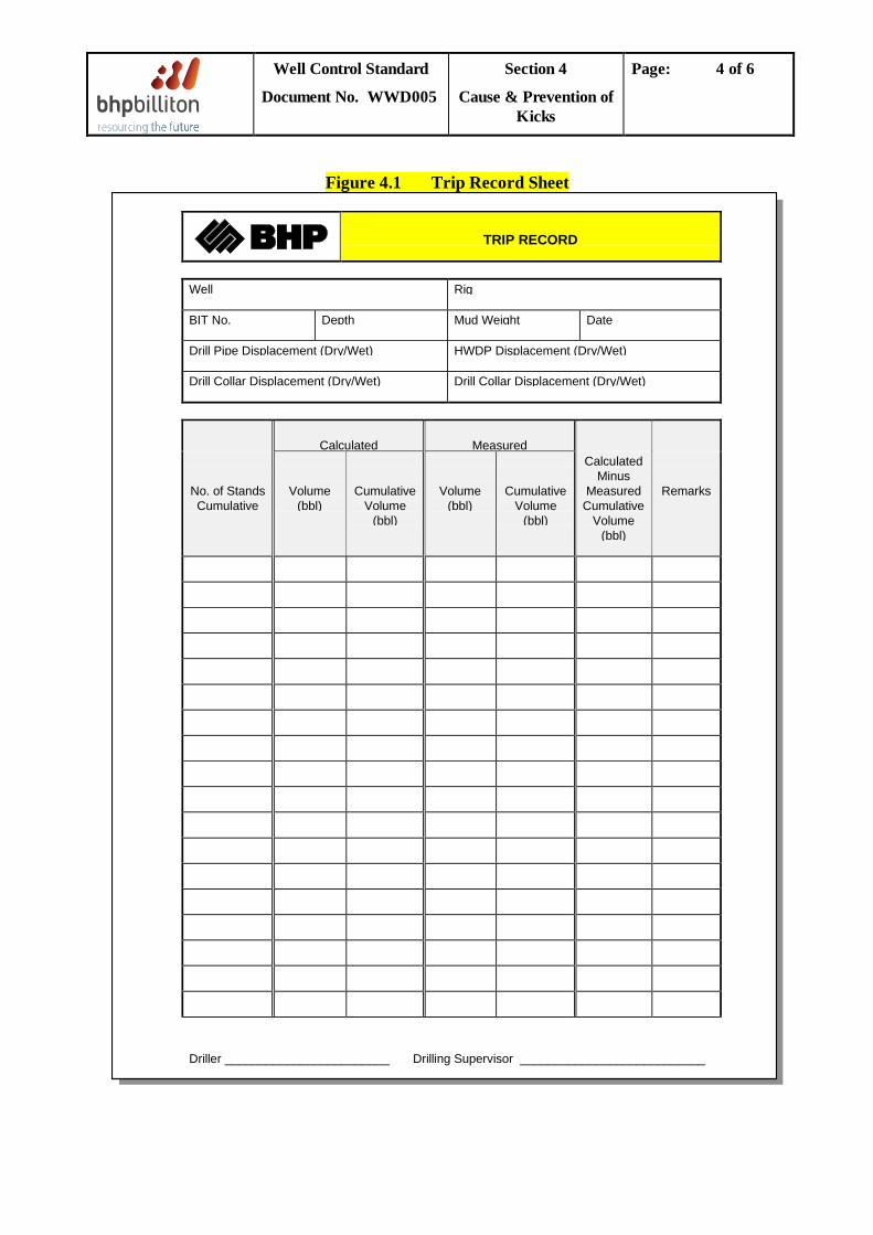
before commencing the trip. • A trip record sheet (see Figure 4.1) must be prepared. The Driller should be told the
reason for the trip and of any indicators of increasing pore pressure or a near balance condition.
c. Safety Valves • Sufficient tested safety valves must be made up with the proper crossovers to fit all string
connections. The valves must be in the 'open' position in preparation for stabbing. • The closing/opening wrench must be readily available for immediate use. • A backup safety valve should be available on the rig floor to be used in the event that the
drill pipe safety valve does not hold pressure, or if stripping in the hole is required and no dart sub is in the string.
d. The drop-in dart for the dart sub shall be correctly maintained and easily accessible on the drill floor. The dart should be physically latched into the dart sub to check for compatibility prior to making up the BHA. BHA IDs above the dart sub should be checked to ensure that the dart will pass. Following risk assessment, the campaign may elect not to run a dart sub in the string, but rather have available on the drill floor
e. Every attempt should be made to cure static losses prior to tripping out of the hole. f. The mud logging and rig floor monitors must be accurately set with alarms activated before
commencement of the trip. g. Flow check for a minimum time of 15 minutes prior to pumping the slug to ensure that the
well is stable with the ECD effect removed. h. Pump a slug. This enables the pipe to be pulled dry and the hole to be accurately monitored. The slug
should be mixed to maintain a minimum of five stands of dry pipe and should be accurately displaced.
Well Control Standard
Document No. WWD005
Section 4
Cause & Prevention of Kicks
Page: 4 of 6
Figure 4.1 Trip Record Sheet
TRIP RECORD
Well Rig
BIT No. Depth Mud Weight Date
Drill Pipe Displacement (Dry/Wet) HWDP Displacement (Dry/Wet)
Drill Collar Displacement (Dry/Wet) Drill Collar Displacement (Dry/Wet)
Calculated Measured
No. of StandsCumulative
Volume(bbl)
CumulativeVolume
(bbl)
Volume(bbl)
CumulativeVolume
(bbl)
CalculatedMinus
MeasuredCumulative
Volume(bbl)
Remarks
Driller ________________________ Drilling Supervisor ___________________________
Well Control Standard
Document No. WWD005
Section 4
Cause & Prevention of Kicks
Page: 5 of 6
4.2.2 Tripping guidelines a. If the overbalance is estimated to be minimal, consideration should be given to conducting a
short trip. After returning to bottom, the overbalance can be assessed from the level of the trip gas at bottoms up and the presence or otherwise of fill.
b. Pull the first 2-5 stands off bottom with the hole fill pump off, monitor the hole visually through the rotary table and ensure that the annulus level drops as pipe is removed from the hole. The pipe wiper should only be installed after the bit is above the shoe. Note: ID pipe wipers should not be dropped until inside the shoe and it has been confirmed that the hole is taking the correct fill.
c. Circulate the hole across the trip tank and monitor hole fill with the aid of the trip sheet. • If the hole does not take the correct amount of fluid, the trip should be stopped and a flow
check must be carried out. • If the flow check indicates no flow and the cause of the discrepancy cannot be accounted
for at surface, the string should be returned to bottom while paying attention to displacement volumes. After circulating bottoms up, consideration should be given to increasing the mud weight before restarting the trip out of the hole.
• If the flow check is positive, the well should be shut in and subsequent action shall be taken dependent upon well conditions.
d. If a trip is interrupted for any reason, it is preferred to continue to circulate the well while monitoring the active pits; otherwise, the safety valve must be installed, closed and the well monitored on the trip tank.
e. Tripping speed must be controlled to minimise swab and surge effects. When drilling in a hole size smaller than 12.1/4”, the DSV must ensure compliance with safe tripping speed as determined by a swab/surge computer programme. This is particularly important on wells with limited kick tolerance. Breaking circulation at the shoe while tripping in will reduce surge effects caused by time related gel strength.
4.3 Prevention Of Kicks While Drilling
4.3.1 Preparation
• The choke and kill manifold shall be lined up for the hard shut-in (see Section 7.1.1). • Ensure pre-recorded data (see Section 4.3.8) is maintained. • A ported float shall be installed in BHA’s. Note that prop-open floats are acceptable and
may be used to eliminate the need for pipe filling on trips in the hole. Proper hole fill-up must be monitored when prop-open floats are used.
• On HPHT wells, where surface pressures in the event of a kick are likely to exceed 3000psi, a high pressure kill assembly or kill stand should be prepared prior to drilling the HPHT section. This comprises a drill pipe pup joint, safety valve and king swivel that can be connected to the cement unit kill line with chiksans.
Well Control Standard
Document No. WWD005
Section 4
Cause & Prevention of Kicks
Page: 6 of 6
4.3.2 Drilling Guidelines a. Flow Checks Warning signs that a kick has occurred while drilling are discussed in Section 6.1. At the
driller’s discretion, or under well-specific standing instructions that must be posted in the doghouse, any one or a combination of these shall justify a flow check. During the flow check, the pipe should be positioned at the correct hang-off height for the upper pipe rams and the string rotated slowly. Flow checking is mandatory in the following circumstances: • Unexplained increase in mud level in the active system. • Increase in percentage returns from flowline. • Drilling breaks in the reservoir section exceeding 1.5 metres (5 feet) in length.
b. Free communication flow between driller, derrick man and mud logger must be maintained, and monitored and encouraged by the Drilling Supervisor. Consideration should be given to providing a hands-free dedicated, UPS-protected talk back system between the driller, derrick man, mud-logger, DPO’s (for DP rigs) and ROV operator (floaters).
c. The mud weight shall be monitored for any reduction that may indicate incorporation of formation fluids.
d. The vacuum degasser shall be run if the measured gas level exceeds 3% to prevent a build up of entrained gas progressively lowering the mud weight.
e. Connection gas peaks shall be closely monitored for increases between successive connections. Other pore pressure indicators (see Section 6.2) should also be continuously monitored, to give early warning of increasing pore pressures.
f. Regular examination of returned cuttings should be made to check for cavings. It is recommended that the mud loggers record and track the percentage of splintery (pressured) and blocky (stressed) cavings in each cutting sample and advise the BHPB Drilling Supervisor of any changes in trend.

Well Control Standard
Document No. WWD005
Section 5
Kick Detection
Page: 1 of 4
TABLE OF CONTENTS
5.1 Warning Signs - Kick in Progress .............................................................................................2
5.2 Pore Pressure Indicators ............................................................................................................3
5.2.1 Gas Levels ........................................................................................................................3
5.2.2 Other indicators ..............................................................................................................3
Well Control Standard
Document No. WWD005
Section 5
Kick Detection
Page: 2 of 4
5.1 Warning Signs - Kick in Progress
One or more of the following warning signs may be associated with the initiation of a kick, all can be caused by other factors:
a.
A gain in pit volume is a definitive indicator of a kick.
Increase in Pit Volume
b.
This is an increase in return flowrate while the pumps are still running at a constant output. This is often the first positive indicator that a kick is occurring, however an influx from a low permeability formation may be difficult to identify.
Increase in Relative Flow
c.
A drilling break generally indicates a change in lithology. The effect on the rate of penetration may also be due to increases in formation porosity, permeability and pore pressure. Breaks may be positive or negative.
Drilling Break
d.
If the volume of drilling mud required to fill the hole while pulling pipe is less than the calculated pipe displacement, formation fluids may be entering the wellbore.
Incorrect Hole Fill
e.
An increase in mud gas level may be due either to a gas flow or to drilled gas. The latter case is a result of drilling a formation with a high gas content, and does not usually become a problem unless the quantity of gas is large and leads to a significant reduction in mud hydrostatic.
Gas Cut Mud
f.
Mud weight reduction (or any significant change in other mud properties, e.g. Chlorides, ES for invert muds, mud resistivity) may indicate a dilution of the mud by formation fluids.
Reduced Mud Weight
g.
A reduction in ECD observed via Pressure While Drilling (PWD) tools may indicate the passage of an influx past, and above, the tools.
Observed ECD (PWD)
h.
A large influx of formation fluid, reduces the hydrostatic pressure in the annulus. The mud in the drill string may U-tube into the annulus and the result is a reduction in pump load and pressure. The pressure reduction can cause the pumps to speed up. Normally if this indicator is seen, a serious kick has occurred and other indicators should be associated with it.
Decrease in Pump Pressure
Well Control Standard
Document No. WWD005
Section 5
Kick Detection
Page: 3 of 4
i.
When an influx displaces the drilling fluid in the wellbore there should be a reduction in the buoyancy of the drill string that may be seen on surface as an increase in the hook load. An increase in hook load is not a reliable method of detecting a kick, because it requires a large influx of low density fluid to produce a measurable hook load increase.
Increase in Hook load
5.2 Pore Pressure Indicators
5.2.1 Gas Levels a.
Background gas is the mud gas content which enters the system when the formation in which it was formerly contained is removed as cuttings. It is unrelated to pore pressure and will occur even in overbalanced drilling conditions. High Background Gas levels that do not respond to small incremental increases in mud weight may indicate a steady flow of gas from an underbalanced, low permeability formation.
Background Gas
b.
Connection gas is caused by the temporary reduction in bottomhole pressure during a connection, due to the combined effects of ECD loss and the swabbing effect of moving the pipe. Connection Gas is characterised as a peak above background gas that is recorded one lag time after the connection
Connection Gas
The presence of Connection Gas indicates pore pressure is less than drilling ECD, and greater than mud hydrostatic during swabbing. Increase in Connection Gas magnitude on successive connections is an indicator of increasing pore pressure.
c.
Trip gas is gas that entered the hole during tripping. Trip gas will be detected in the mud on circulating bottoms up after a trip.
Trip Gas
If the static mud column is sufficient to balance the formation pressure, the trip gas is a result of swabbing and osmosis from the gas bearing formation. The gas may be held in suspension by the gel strength of the mud, and only appear on surface after subsequently circulating bottoms up.
Significant trip gas may indicate that a close to balance situation exists in the hole.
5.2.2 Other indicators a.
Any cuttings that have not been created by bit action are termed ‘cavings’. Pressure cavings are long, splintered, fresh and angular and form when overpressure causes the shale borehole wall to crack and burst into the well. It is important to be able to distinguish between such splintered, fresh cavings and ‘blocky’ cavings that are not pressured and not ‘fresh’.
Shale Cavings
b. Chloride Trends
Well Control Standard
Document No. WWD005
Section 5
Kick Detection
Page: 4 of 4
Chloride trends may indicate increasing pore pressures. Theoretically, over pressured shale has a higher water content and hence higher salinity than normal; however this does not always hold true and the indicator may be unreliable unless the chloride response is already known for the area. Continuous measurement of the mud resistivity both in and out of the hole allows monitoring of the trend. (Mud additives and make-up water can affect resistivity and chloride measurements).
c.
Shale density normally increases with depth but this trend is reversed in abnormally pressured zones. The density of the cuttings is measured and plotted versus depth. Any deviation from the normal trend line may be interpreted as a pore pressure change.
Decrease in Shale Density
d.
A change in temperature gradient is often associated with an abnormally pressured formation. The limitation of this method is that the mud temperature can usually only be measured on surface and is subject to external influences.
Temperature Measurements
e.
Formation changes may be detected by real-time formation evaluation tools run in the BHA. Tools are currently available to measure resistivity/gamma-ray, compressional and shear sonic and to perform a VSP “look ahead” investigation; this latter can be produced by processing, but not in real time. Although this is not strictly a pore pressure indicator, the interpretation of such data can aid in the identification of overpressure.
Logging While Drilling
Well Control Standard
Document No. WWD005
Section 6
Well Shut-in & Data Recording
Page: 1 of 10
TABLE OF CONTENTS
6.1 Hard-Shut-in Method ...............................................................................................................2
6.1.2 Special Shut-In Situations ..............................................................................................2
6.2 Data Recording ..........................................................................................................................9
6.2.1 Data Requirements .........................................................................................................9
6.2.2 Confirmation Of Shut-In Pressures .............................................................................9
6.2.3 High Pressure Kill Assembly ...................................................................................... 10
Well Control Standard
Document No. WWD005
Section 6
Well Shut-in & Data Recording
Page: 2 of 10
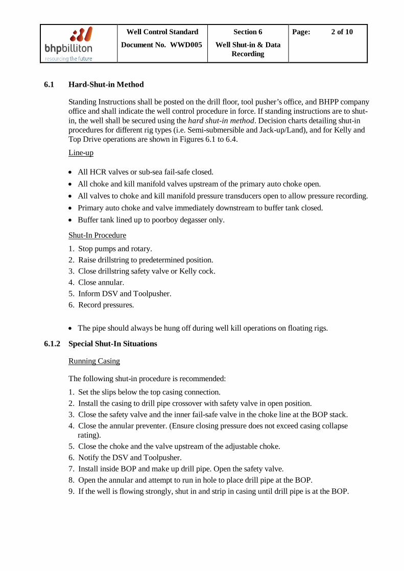
6.1 Hard-Shut-in Method
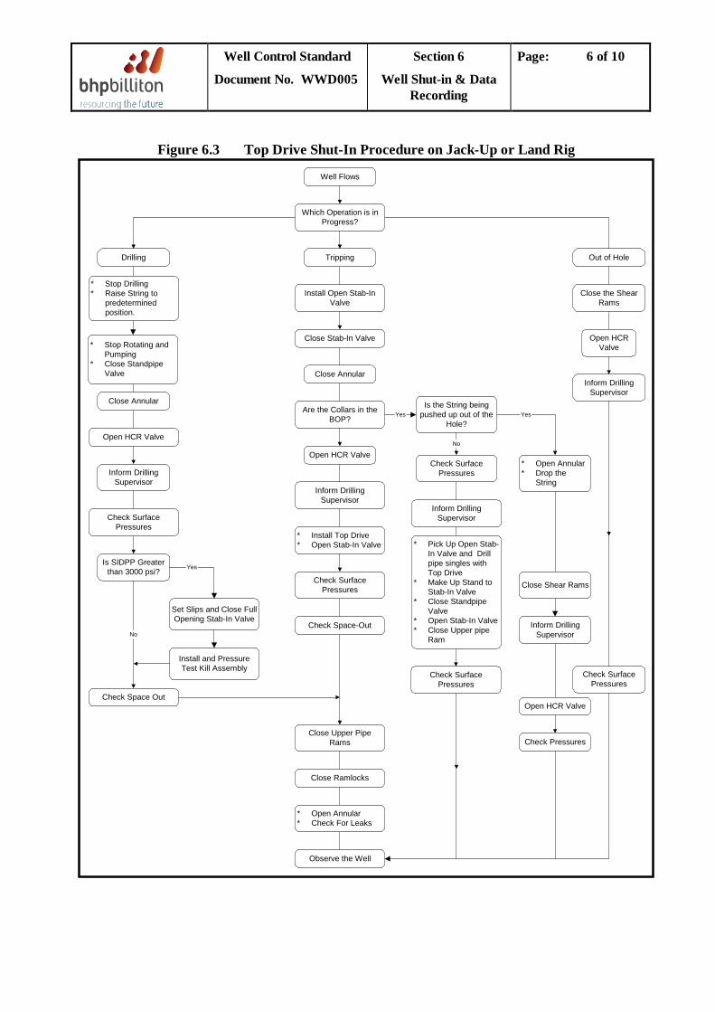
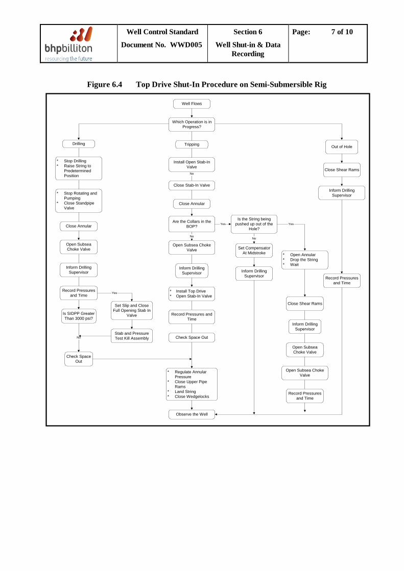
Standing Instructions shall be posted on the drill floor, tool pusher’s office, and BHPP company office and shall indicate the well control procedure in force. If standing instructions are to shut-in, the well shall be secured using the hard shut-in method. Decision charts detailing shut-in procedures for different rig types (i.e. Semi-submersible and Jack-up/Land), and for Kelly and Top Drive operations are shown in Figures 6.1 to 6.4.
Line-up
• All HCR valves or sub-sea fail-safe closed. • All choke and kill manifold valves upstream of the primary auto choke open. • All valves to choke and kill manifold pressure transducers open to allow pressure recording. • Primary auto choke and valve immediately downstream to buffer tank closed. • Buffer tank lined up to poorboy degasser only.
1. Stop pumps and rotary.
Shut-In Procedure
2. Raise drillstring to predetermined position. 3. Close drillstring safety valve or Kelly cock. 4. Close annular. 5. Inform DSV and Toolpusher. 6. Record pressures. • The pipe should always be hung off during well kill operations on floating rigs.
6.1.2 Special Shut-In Situations
The following shut-in procedure is recommended:
Running Casing
1. Set the slips below the top casing connection. 2. Install the casing to drill pipe crossover with safety valve in open position. 3. Close the safety valve and the inner fail-safe valve in the choke line at the BOP stack. 4. Close the annular preventer. (Ensure closing pressure does not exceed casing collapse
rating). 5. Close the choke and the valve upstream of the adjustable choke. 6. Notify the DSV and Toolpusher. 7. Install inside BOP and make up drill pipe. Open the safety valve. 8. Open the annular and attempt to run in hole to place drill pipe at the BOP. 9. If the well is flowing strongly, shut in and strip in casing until drill pipe is at the BOP.

Well Control Standard
Document No. WWD005
Section 6
Well Shut-in & Data Recording
Page: 3 of 10
The following procedure is recommended:
Logging
1. Cease wireline operations and close the well on the upper annular. 2. Open kill line valves and begin to record shut-in pressure and pit gain.
Note: If possible the wireline should be pulled or stripped out of the hole. The shear rams should be considered as a last resort and used only if the annular(s) fail to secure the well.
Well Control Standard
Document No. WWD005
Section 6
Well Shut-in & Data Recording
Page: 4 of 10
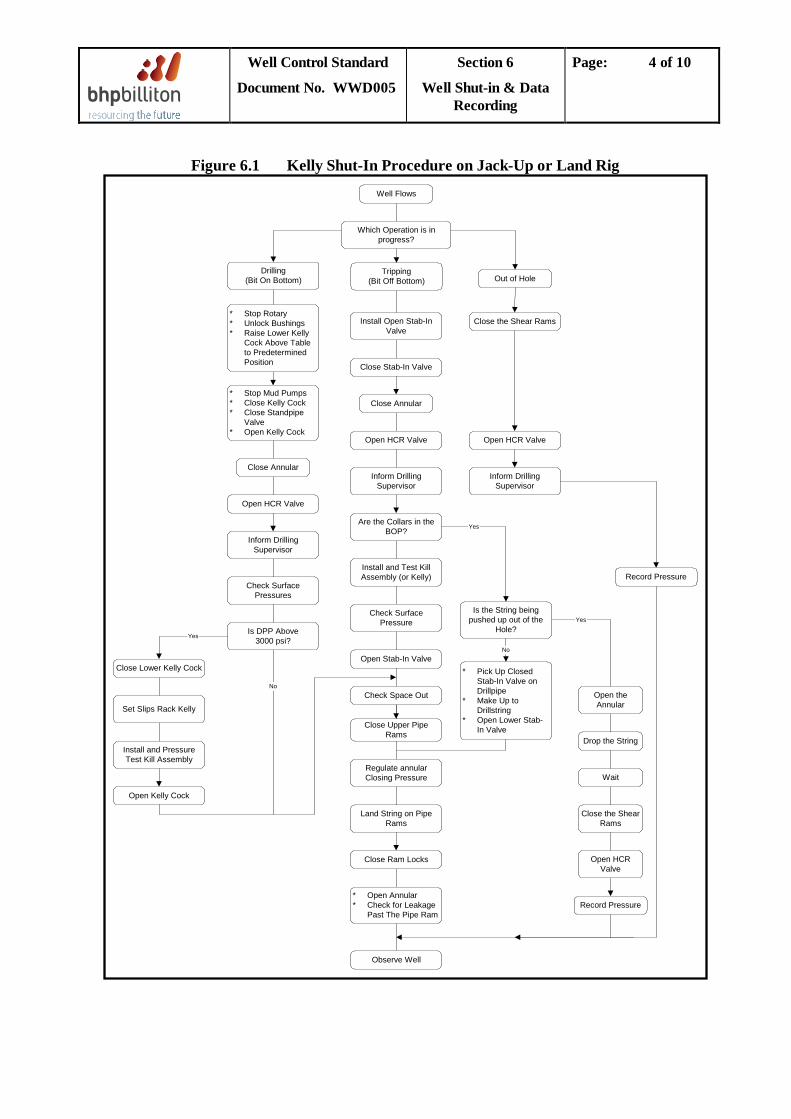
Figure 6.1 Kelly Shut-In Procedure on Jack-Up or Land Rig
No
Yes
Well Flows
Which Operation is inprogress?
Tripping(Bit Off Bottom)
Install Open Stab-InValve
Close Stab-In Valve
Close Annular
Open HCR Valve
Inform DrillingSupervisor
Are the Collars in theBOP?
Install and Test KillAssembly (or Kelly)
Check SurfacePressure
Open Stab-In Valve
Check Space Out
Close Upper PipeRams
Regulate annularClosing Pressure
Land String on PipeRams
Close Ram Locks
* Open Annular* Check for Leakage
Past The Pipe Ram
Observe Well
* Pick Up ClosedStab-In Valve onDrillpipe
* Make Up toDrillstring
* Open Lower Stab-In Valve
Is the String beingpushed up out of the
Hole?
Inform DrillingSupervisor
Open HCR Valve
Close the Shear Rams
Out of HoleDrilling
(Bit On Bottom)
* Stop Rotary* Unlock Bushings* Raise Lower Kelly
Cock Above Tableto PredeterminedPosition
* Stop Mud Pumps* Close Kelly Cock* Close Standpipe
Valve* Open Kelly Cock
Close Annular
Open HCR Valve
Inform DrillingSupervisor
Check SurfacePressures
Is DPP Above3000 psi?
Close Lower Kelly Cock
Set Slips Rack Kelly
Install and PressureTest Kill Assembly
Open Kelly Cock
Record Pressure
Yes
Open theAnnular
Drop the String
Wait
Close the ShearRams
Open HCRValve
Record Pressure
No
Yes
Well Control Standard
Document No. WWD005
Section 6
Well Shut-in & Data Recording
Page: 5 of 10
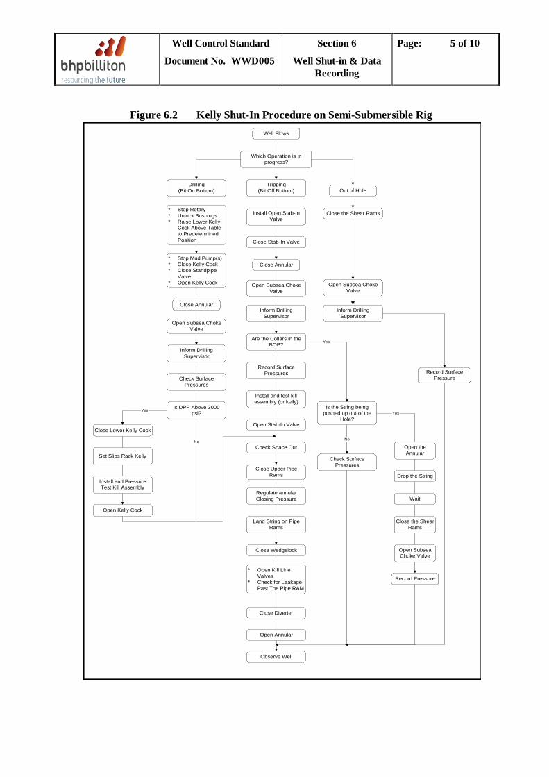
Figure 6.2 Kelly Shut-In Procedure on Semi-Submersible Rig
No
Yes
Well Flows
Which Operation is inprogress?
Tripping(Bit Off Bottom)
Install Open Stab-InValve
Close Stab-In Valve
Close Annular
Open Subsea ChokeValve
Inform DrillingSupervisor
Are the Collars in theBOP?
Record SurfacePressures
Install and test killassembly (or kelly)
Open Stab-In Valve
Check Space Out
Close Upper PipeRams
Regulate annularClosing Pressure
Land String on PipeRams
Close Wedgelock
* Open Kill LineValves
* Check for LeakagePast The Pipe RAM
Close Diverter
Check SurfacePressures
Is the String beingpushed up out of the
Hole?
Inform DrillingSupervisor
Open Subsea ChokeValve
Close the Shear Rams
Out of HoleDrilling
(Bit On Bottom)
* Stop Rotary* Unlock Bushings* Raise Lower Kelly
Cock Above Tableto PredeterminedPosition
* Stop Mud Pump(s)* Close Kelly Cock* Close Standpipe
Valve* Open Kelly Cock
Close Annular
Open Subsea ChokeValve
Inform DrillingSupervisor
Check SurfacePressures
Is DPP Above 3000psi?
Close Lower Kelly Cock
Set Slips Rack Kelly
Install and PressureTest Kill Assembly
Open Kelly Cock
Record SurfacePressure
Yes
Open theAnnular
Drop the String
Wait
Close the ShearRams
Open SubseaChoke Valve
Record Pressure
No
Yes
Open Annular
Observe Well
Well Control Standard
Document No. WWD005
Section 6
Well Shut-in & Data Recording
Page: 6 of 10
Figure 6.3 Top Drive Shut-In Procedure on Jack-Up or Land Rig
Well Flows
Which Operation is inProgress?
Tripping
Install Open Stab-InValve
Close Stab-In Valve
Close Annular
Are the Collars in theBOP?
Open HCR Valve
Inform DrillingSupervisor
* Install Top Drive* Open Stab-In Valve
Check SurfacePressures
Check Space-Out
Close Upper PipeRams
Close Ramlocks
* Open Annular* Check For Leaks
Observe the Well
Drilling
* Stop Drilling* Raise String to
predeterminedposition.
* Stop Rotating andPumping
* Close StandpipeValve
Close Annular
Open HCR Valve
Inform DrillingSupervisor
Check SurfacePressures
Is SIDPP Greaterthan 3000 psi?
Check Space Out
Set Slips and Close FullOpening Stab-In Valve
Install and PressureTest Kill Assembly
Is the String beingpushed up out of the
Hole?
Check SurfacePressures
Inform DrillingSupervisor
* Pick Up Open Stab-In Valve and Drillpipe singles withTop Drive
* Make Up Stand toStab-In Valve
* Close StandpipeValve
* Open Stab-In Valve* Close Upper pipe
Ram
Check SurfacePressures
Out of Hole
* Open Annular* Drop the
String
Close Shear Rams
Inform DrillingSupervisor
Open HCR Valve
Check Pressures
Check SurfacePressures
Close the ShearRams
Open HCRValve
Inform DrillingSupervisor
No
Yes
YesYes
No
Well Control Standard
Document No. WWD005
Section 6
Well Shut-in & Data Recording
Page: 7 of 10
Figure 6.4 Top Drive Shut-In Procedure on Semi-Submersible Rig
No
No
Well Flows
Which Operation is inProgress?
Tripping
Install Open Stab-InValve
Close Stab-In Valve
Close Annular
Are the Collars in theBOP?
Open Subsea ChokeValve
Inform DrillingSupervisor
* Install Top Drive* Open Stab-In Valve
Record Pressures andTime
Check Space Out
* Regulate AnnularPressure
* Close Upper PipeRams
* Land String* Close Wedgelocks
Observe the Well
Set Slip and CloseFull Opening Stab In
Valve
Stab and PressureTest Kill Assembly
Check SpaceOut
Is SIDPP GreaterThan 3000 psi?
Record Pressuresand Time
Inform DrillingSupervisor
Open SubseaChoke Valve
Close Annular
* Stop Rotating andPumping
* Close StandpipeValve
* Stop Drilling* Raise String to
PredeterminedPosition
Drilling
Is the String beingpushed up out of the
Hole?
Set CompensatorAt Midstroke
Inform DrillingSupervisor
* Open Annular* Drop the String* Wait
Close Shear Rams
Inform DrillingSupervisor
Open SubseaChoke Valve
Open Subsea ChokeValve
Record Pressuresand Time
Record Pressuresand Time
Out of Hole
Close Shear Rams
Inform DrillingSupervisor
Yes
Yes Yes
No
No
Well Control Standard
Document No. WWD005
Section 6
Well Shut-in & Data Recording
Page: 8 of 10
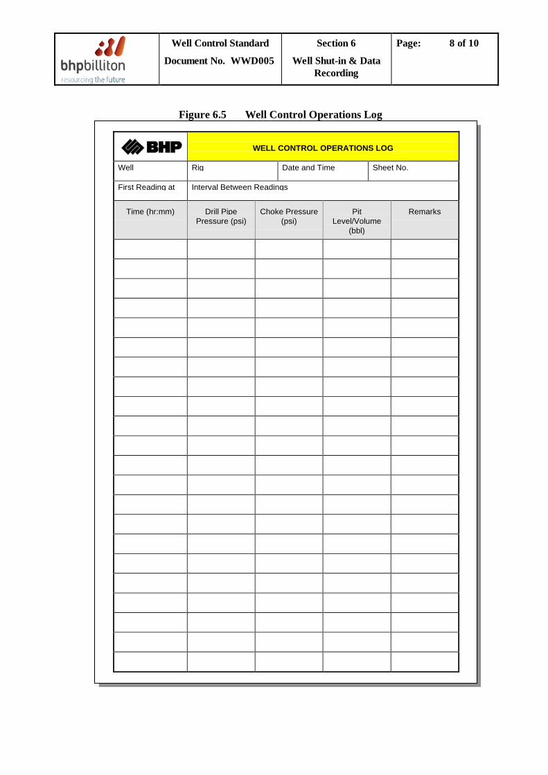
Figure 6.5 Well Control Operations Log
WELL CONTROL OPERATIONS LOG
Well Rig Date and Time Sheet No.
First Reading at Interval Between Readings
Time (hr:mm) Drill PipePressure (psi)
Choke Pressure(psi)
PitLevel/Volume
(bbl)
Remarks
Well Control Standard
Document No. WWD005
Section 6
Well Shut-in & Data Recording
Page: 9 of 10
6.2 Data Recording
6.2.1 Data Requirements
The following data shall be monitored and recorded on the Well Control Operations Log (see Figure 6.5) at the drill floor throughout a well kill operation (the Mug Loggers must also manually record all volume and surface pressure data on a continual basis, primarily as back up to the data being recorded by the logging unit computer system).
a. Times. b. Pressure Data (from Auto-Choke Control Panel). Pressures shall be recorded at one minute
intervals until they have stabilised. Thereafter the frequency of recording shall be as directed by the DSV: • The shut-in casing pressure (SICP). • Drill pipe pressure. In order to measure the shut-in drill pipe pressure (SIDPP) when a
float valve or other drill string non-return valve is installed, the valve must be pumped open. With the mud pumps lined up on the drill pipe pump very slowly to the well while monitoring both the pump and casing pressures. Record and plot the increase in pump pressure against the volume of mud pumped. The pump pressure will increase sharply initially; the first indication of pump pressure stabilising or casing pressure increasing signifies the float valve open, and true SIDPP can be observed (if this pressure is greater than 80% of the rated working pressure of the standpipe, swivel or rotary hose, the high pressure kill assembly must be installed, see Section 6.2.3).
c. Active pit volume. d. Description of events.
6.2.2 Confirmation Of Shut-In Pressures
Before commencing kill calculations. The pressure must be confirmed using the following guidelines.
a. Choke line fluid in sub-sea wells If the mud in the choke line has a different weight from active mud, this must be taken into account when calculating influx density and anticipated surface pressures. Note that it is preferable to isolate the well and circulate the choke and kill lines to active mud before commencing well kill operations.
b. SIDPP > SICP This shall not be automatically assumed to be a kick inside the drill pipe. Other reasons may be: • Annulus loaded with cuttings. • Light mud pumped down the drill pipe; all pit levels should be checked to ensure mud
stocks are correct. • Gauge error; check and replace gauges.
Well Control Standard
Document No. WWD005
Section 6
Well Shut-in & Data Recording
Page: 10 of 10
c. Trapped Pressure If the initial shut-in pressures do not increase, this indicates that either the influx is not migrating (i.e. the influx is not gas), or pressure has been trapped below the BOPs as a result of pipe movement through the preventer or dynamic system pressure which did not dissipate before the preventer closed. Trapped pressure will result in overkill if not bled-off. Check for trapped pressure by slowly bleeding off mud via a manual choke to the stripping tank or trip tank: i. A fixed increment should be bled off (50 psi or 0.5 bbl). ii. The well should be closed in to allow pressures to stabilise. iii. If drill pipe pressure decreases, there is trapped pressure. More mud should be bled off in
fixed increments. iv. When the drill pipe pressure no longer decreases, drill pipe pressure shall be taken as
SIDPP. Note: In formations prone to ballooning, typically characterized by incremental decreases in SIDPP when following the above procedure, the forward course of action shall be discussed and agreed with the BHPB Drilling Superintendent.
6.2.3 High Pressure Kill Assembly If circulating pressures are in excess of 80% of the surface equipment, the high pressure kill assembly shall be installed above the closed drill string safety valve and a chiksan line run to the cement unit kill standpipe (see Section 4.3.1).
Well Control Standard
Document No. WWD005
Section 7
Well Control Methods
Page: 1 of 17
TABLE OF CONTENTS
7.1 Introduction .................................................................................................................................27.2 Circulation Kill Methods ...........................................................................................................2
7.2.1 Advantages and Disadvantages of Circulation Kill Methods ...................................27.2.2 Calculations Prior to Circulating .................................................................................3
7.2.2.1 Drill string and Annulus Volumes ....................................................................37.2.2.2 Kill Mud Weight .................................................................................................37.2.2.3 Barite Required ..................................................................................................37.2.2.4 Influx Gradient ...................................................................................................3
7.2.3 Wait And Weight Method ..............................................................................................47.2.3.1 Preparation of Kill Graph (Figure 7.1, Well Kill Worksheet) ....................47.2.3.2 Well Killing Procedure .....................................................................................67.2.3.3 Concurrent Method .........................................................................................6
7.2.4 The Driller's Method ......................................................................................................77.2.4.1 First Circulation ..............................................................................................77.2.4.2 Second Circulation ..........................................................................................7
7.3 Volumetric Method .....................................................................................................................87.3.1 Principle of Volumetric Method ...................................................................................97.3.2 Static Volumetric Control procedure ...........................................................................9
7.4 Combined Stripping And Volumetric Method ...................................................................... 127.4.1 Principle ........................................................................................................................ 127.4.2 Practical Considerations ............................................................................................. 12
7.4.2.1 Preparation .............................................................................................................. 127.4.2.2 Choice of Preventer ................................................................................................ 127.4.2.3 Measurement of Volumes and Pressures ............................................................. 137.4.2.4 Effect of Adding Pipe .............................................................................................. 137.4.2.5 Effect of Influx Migration ...................................................................................... 137.4.2.6 Effect of Entering the Influx ................................................................................. 137.4.2.7 Assumptions ............................................................................................................. 13
7.4.3 Combined Stripping and Volumetric Kill Procedure .............................................. 147.4.3.1 Shut-In and Initial Calculation .............................................................................. 147.4.3.2 Stripping into the Hole ........................................................................................... 15
7.4.4 Alternative combined volumetric and stripping procedure .................................. 157.5 Bullheading ............................................................................................................................... 17
Well Control Standard
Document No. WWD005
Section 7
Well Control Methods
Page: 2 of 17
7.1 Introduction
After a well has been safely shut in on an influx, the choice of Well Kill or Well Control method can be made based on the pre-recorded data (Section 4.3), and shut-in pressure data (Section 7.2).
The objective should always be to kill the well as quickly and safely as possible, maintaining bottomhole pressure (BHP) constant at a value greater than formation pressure by a calculated safety margin.
The principle of constant bottomhole pressure is essentially followed for all methods discussed in this section, except Bullheading.
A stripping procedure is covered in Section 7.4. Although this is not itself a Well Control method, it is required in certain cases before one may be implemented.
7.2 Circulation Kill Methods This section details the Wait and Weight (W&W), and Driller’s methods. Both techniques ensure that bottomhole pressure is maintained constant and equal to, or slightly greater than, formation pressure.
7.2.1 Advantages and Disadvantages of Circulation Kill Methods
The advantages of the W&W over the Driller’s method are as follows:
• Maintains constant bottomhole pressure while imposing lower pressure on the formation. • Results in lower surface pressures. • Only one circulation is required to kill the well, hence less circulating time and less wear on
BOP equipment. • The well and well control equipment will be under pressure for less time.
The Driller's method requires two complete hole circulations to kill the well. The first circulation displaces the kick out of the hole with the original mud. The kill weight mud is prepared and a further circulation carried out to kill the well. During the first circulation, the choke pressures will be higher than those during the W&W method. Pressures at the casing shoe will also be higher when using the Driller’ Method unless the open-hole annular capacity is smaller than the capacity of the drill pipe, in which case any influx will reach the shoe before kill weight mud reaches the bit.
The Driller’s method should be considered instead of the W&W method in the following situations:
• If there are insufficient stocks of weighting material at the rig site and the mud weighting system is not capable of increasing active mud weight to kill mud weight while circulating.
• If there is some considerable doubt as to the mud weight required to kill the well. • If impending bad weather dictates that the kick must be displaced from the hole as quickly
as possible.
Disadvantages of the Driller's method include the following:
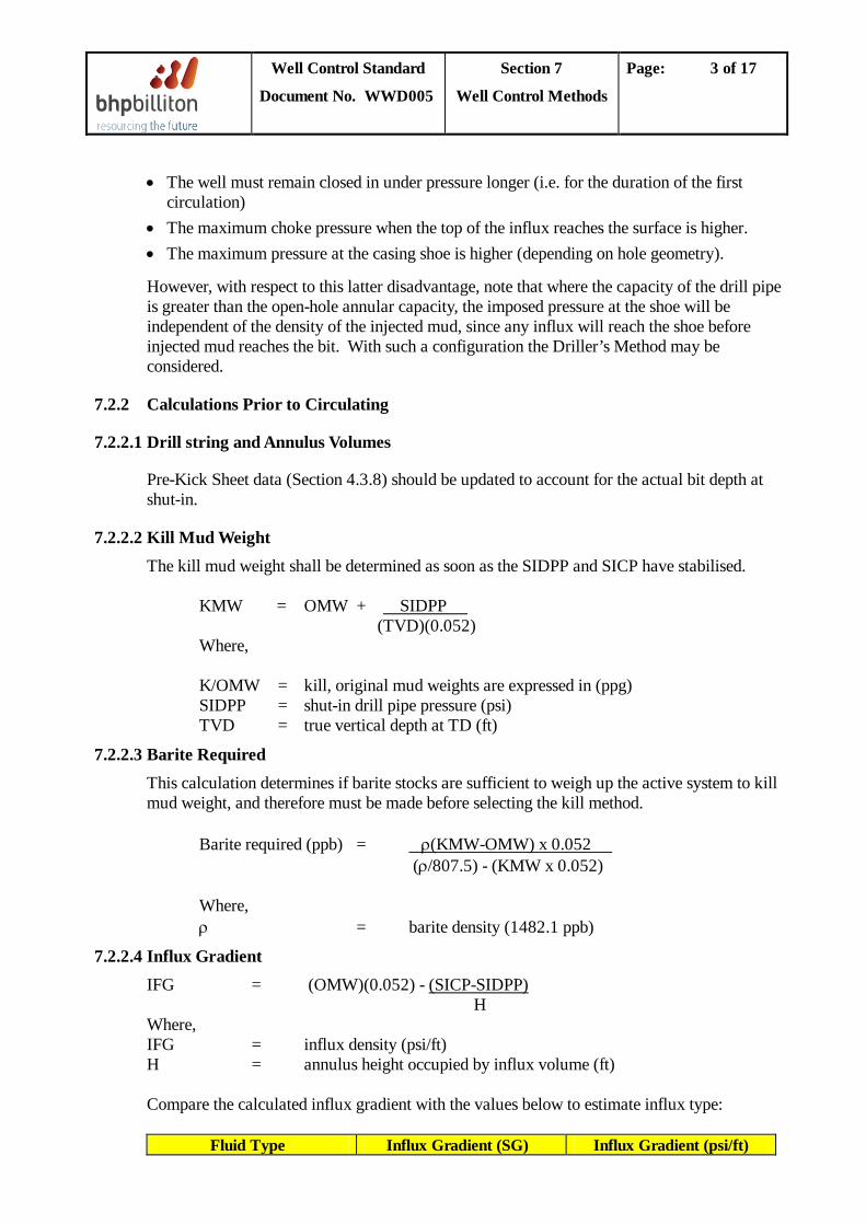
Well Control Standard
Document No. WWD005
Section 7
Well Control Methods
Page: 3 of 17
• The well must remain closed in under pressure longer (i.e. for the duration of the first circulation)
• The maximum choke pressure when the top of the influx reaches the surface is higher. • The maximum pressure at the casing shoe is higher (depending on hole geometry).
However, with respect to this latter disadvantage, note that where the capacity of the drill pipe is greater than the open-hole annular capacity, the imposed pressure at the shoe will be independent of the density of the injected mud, since any influx will reach the shoe before injected mud reaches the bit. With such a configuration the Driller’s Method may be considered.
7.2.2 Calculations Prior to Circulating
7.2.2.1 Drill string and Annulus Volumes
Pre-Kick Sheet data (Section 4.3.8) should be updated to account for the actual bit depth at shut-in.
7.2.2.2 Kill Mud Weight The kill mud weight shall be determined as soon as the SIDPP and SICP have stabilised. KMW = OMW + (TVD)(0.052)
SIDPP
Where, K/OMW = kill, original mud weights are expressed in (ppg) SIDPP = shut-in drill pipe pressure (psi) TVD = true vertical depth at TD (ft)
7.2.2.3 Barite Required This calculation determines if barite stocks are sufficient to weigh up the active system to kill mud weight, and therefore must be made before selecting the kill method. Barite required (ppb) =
(ρ/807.5) - (KMW x 0.052) ρ(KMW-OMW) x 0.052
Where, ρ = barite density (1482.1 ppb)
7.2.2.4 Influx Gradient IFG = (OMW)(0.052) - H
(SICP-SIDPP)
Where, IFG = influx density (psi/ft) H = annulus height occupied by influx volume (ft)
Compare the calculated influx gradient with the values below to estimate influx type:
Fluid Type Influx Gradient (SG) Influx Gradient (psi/ft)
Well Control Standard
Document No. WWD005
Section 7
Well Control Methods
Page: 4 of 17
Gas 0.12 - 0.46 .052 - 0.199 Oil 0.69 - 0.92 0.299 - 0.398
Water > 0.92 > 0.398
7.2.3 Wait And Weight Method The preferred kill method in WWD for all under-balanced kicks is the Wait and Weight Method. Example calculations for the W&W method are provided in Appendix 1.
7.2.3.1 Preparation of Kill Graph (Figure 7.1, Well Kill Worksheet)
The standpipe pressure at the start of the circulating operation (Pic - Initial Circulating Pressure) is the sum of the SIDPP and the pump pressure at the slow circulating rate (PSCR
P
).
ic = PSCR
The circulating pressure when the kill mud reaches the bit (P
+ SIDPP
fc
- Final Circulating Pressure) is calculated as follows:
P = P x (psi)fc SCRKill Mud Weight
Original Mud Weight
The standpipe pressure versus volume pumped or time should be plotted. Standpipe pressures should include a safety margin (use 150 psi) to allow for choke operator reaction time.
The procedure is as follows:
1. Plot the initial standpipe pressure (Pic
2. Plot the standpipe pressure when kill mud has reached the bit (P) at time (or volume) zero.
fc
3. Connect the two points with a straight line. This line represents the standpipe pressure whilst pumping the kill mud from the surface to the bit.
).
4. Note: Where a tapered drill string is in use, Pic and Pfc will be joined by 2 lines of different gradients due to the non-linear relationship between volume pumped and depth of kill mud.
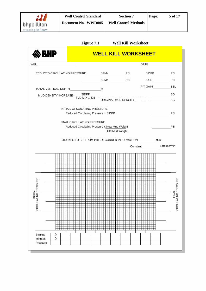
Well Control Standard
Document No. WWD005
Section 7
Well Control Methods
Page: 5 of 17
Figure 7.1 Well Kill Worksheet
WELL
REDUCED CIRCULATING PRESSURE
DATE
SPM= PSI
SPM= PSI
TOTAL VERTICAL DEPTH m
MUD DENSITY INCREASE= SIDPPTVD M X 1.421
SIDPP PSI
SICP PSI
PIT GAIN BBL
SG
SGORIGINAL MUD DENSITY
INITIAIL CIRCULATING PRESSUREReduced Circulating Pressure + SIDPP PSI
FINAL CIRCULATING PRESSUREReduced Circulating Pressure x New Mud WeightReduced Circulating Pressure x Old Mud Weight
PSI
STROKES TO BIT FROM PRE-RECORDED INFORMATION stks
Constant Strokes/min
00
StrokesMinutesPressure
FIN
AL
CIR
CU
LATI
NG
PR
ES
SU
RE
INIT
IAL
CIR
CU
LATI
NG
PR
ES
SU
RE
WELL KILL WORKSHEET
Well Control Standard
Document No. WWD005
Section 7
Well Control Methods
Page: 6 of 17
7.2.3.2 Well Killing Procedure 1. Zero stroke counter. Start the pump slowly while simultaneously opening the remote
adjustable choke. 2. Increase pump speed to the selected kill pump rate while maintaining kill line pressure
constant. • The kill line shall be used to monitor wellhead pressure to account for choke line pressure
drop. This is critical in deep water sub-sea wells. • Where stack-mounted gauges are available, constant pressure start-up can be monitored
directly. Stack-mounted gauge readouts should be clearly visible at all times to the choke operator.
3. After the pump is up to speed, read and record the Initial Circulating Pressure (Pic). The actual Pic should be compared to the calculated value and, if required, adjustment made to the drillpipe pressure schedule to account for any differences between the two values. In all cases, use the actual Pic
• If choke line contains fluid other than active weight mud, the kill line (wellhead) pressure should be held constant until choke line is displaced to mud. The P
rather than the calculated value.
ic
4. Maintain the drillpipe pressure as per the drillpipe pressure schedule. Maintain constant pump speed throughout circulation.
shall be recorded at this point and the drillpipe pressure schedule adjusted accordingly.
5. After the kill mud reaches the bit, maintain the drillpipe pressure constant at the Pfc
6. When kill mud reaches surface, shut down the pump and close the choke. Check drillpipe and casing for pressure. If drillpipe and casing pressures are recorded, bleed off pressures to check for trapped pressure. If the well is not dead, resume circulation to ensure uniform kill mud throughout wellbore.
by choke adjustment until kill mud reaches surface.
7. If drillpipe and casing pressures equal zero, flow check through the choke line. 8. If well is dead proceed with clearing stack gas. 9. Circulate wellbore conventionally and add a suitable overbalance to the mud weight.
Notes: • If it is necessary to stop pumping at any time during the well circulation, immediately
shut-in the well. To resume pumping, maintain kill line (wellhead) pressure constant while bringing the pump up to speed to account for choke line pressure drop. Pic
• Example calculations for the W&W circulation kill method are shown in Appendix 1.
shall be re-checked as per Step 3, and the drill pipe schedule adjusted if necessary.
7.2.3.3 Concurrent Method
This method is a variation of W&W, used when it is not possible to weigh up the mud system to kill weight at once, but when the Driller’s method will result in unacceptably high well bore pressure.
The mud weight is increased in stages until the well is full of kill weight mud, with each new weight being circulated all the way to surface. A new drill pipe schedule is constructed for each circulation as per W&W
Well Control Standard
Document No. WWD005
Section 7
Well Control Methods
Page: 7 of 17
7.2.4 The Driller's Method
7.2.4.1 First Circulation
A kill graph is not required for the first circulation, since drill pipe pressure will be maintained constant at Pic after bringing the pump up to speed. Pic
P
should be estimated prior to commencing circulation:
ic = PSCR
The procedure for the first circulation is as follows:
+ SIDPP (psi)
1. Zero stroke counter. Start the pump slowly while simultaneously opening the remote adjustable choke.
2. Increase pump speed to the selected kill pump rate while maintaining kill line (wellhead) pressure constant to account for choke line pressure drop. • Where stack-mounted gauges are available, constant pressure start-up can be monitored
directly. Stack-mounted gauge readouts should be clearly visible at all times to the choke operator.
3. After the pump is up to speed read and record the Pic. The actual Pic
• In all cases maintain the drillpipe pressure constant at the actual P
should be compared to the calculated value to check for discrepancies.
ic throughout the circulation. Maintain constant pump rate. If actual Pic differs significantly from calculated Pic, calculate the actual SCR pressure to be used for determining Pfc
• If the choke line contains fluid other than active weight mud, the kill line (wellhead) pressure should be held constant until choke line is displaced to mud. The P
for the second circulation.
ic
4. When the influx has been circulated out of the well stop the pump and shut the well in at the choke. Read and record SICP and SIDPP. If the influx has been totally removed SICP should equal SIDPP.
shall be recorded at this point.
7.2.4.2 Second Circulation a. Preparation of Kill Graph (see Figure 7.1):
The stand pipe pressure at the start of the second circulation (Pic
P = P x (psi)fc ACTUALKill Mud Weight
Original Mud Weight
) may be taken as the actual circulating pressure at the end of the first circulation. The circulating pressure when the kill mud reaches the bit shall be calculated as follows:
The standpipe pressure versus volume pumped or time should be plotted. Standpipe pressures should include a safety margin (use 150 psi) to allow for choke operator reaction time.
Well Control Standard
Document No. WWD005
Section 7
Well Control Methods
Page: 8 of 17
The procedure is as follows: 1. Plot the initial standpipe pressure (Pic
2. Plot the standpipe pressure when kill mud has reached the bit (P) at the start of the second circulation.
fc
3. Connect the two points with a straight line. This line represents the standpipe pressure whilst pumping the kill mud from the surface to the bit.
).
b. Well Killing Procedure
1. Zero stroke counter. Start the pump slowly while simultaneously opening the adjustable choke.
2. Increase pump speed to the selected kill pump rate while maintaining kill line pressure constant to account for choke line pressure losses. • Where stack-mounted gauges are available, constant pressure start-up can be
monitored directly. Stack-mounted gauge readouts should be clearly visible at all times to the choke operator.
3. After the pump is up to speed, read and record the Pic.. The actual Pic. should be compared to the calculated value, and if required, adjustment made to the drillpipe pressure schedule to account for any differences between the two values. In all cases, use the actual Pic
4. Maintain the drillpipe pressure as per the drillpipe pressure schedule. Maintain constant pump speed throughout circulation.
. rather than the calculated value.
5. After kill mud reaches the bit, maintain the drillpipe pressure constant at the Pfc
6. When kill mud reaches surface shut down the pump and close the choke. Check drillpipe and casing for pressure. If drillpipe and casing pressures are recorded, bleed off pressures to check for trapped pressure. if the well is not dead, resume circulation to ensure uniform kill weight mud throughout wellbore.
by choke adjustment until kill mud reaches surface.
7. If drillpipe and casing pressures equal zero, flow check through the choke line. 8. If well is dead proceed with clearing stack gas. 9. Circulate wellbore conventionally and add a suitable overbalance to the mud weight. Note: If it is necessary to stop pumping at any time during the well circulation,
immediately shut-in the well. To resume pumping, maintain kill line (wellhead) pressure constant while bringing the pump up to speed to account for choke line pressure drop. Pic
7.3 Volumetric Method
shall be re-checked as per Step 3, and the drill pipe schedule adjusted if necessary.
The volumetric method is not a well killing technique. When the implementation of a circulation kill method is delayed or impossible, the method is used to prevent bottomhole pressure rising excessively as an influx migrates to surface.
The volumetric may be have to be used for any of the following reasons:
• Drill string out of hole. • Combined stripping and volumetric method (see Section 7.4) • Drill string cannot be stripped to bottom.
Well Control Standard
Document No. WWD005
Section 7
Well Control Methods
Page: 9 of 17
• Washed out or parted drill string. • Plugged bit. • Circulation kill methods cannot be used.
7.3.1 Principle of Volumetric Method
If no control is placed on a migrating gas influx, it percolates up the well bore without expansion carrying formation pressure. The bottomhole pressure increases because the mud column below the influx becomes progressively longer while the influx pressure remains constant. The method requires mud to be bled-off at constant casing pressure in a series of controlled expansions as the influx migrates.
7.3.2 Static Volumetric Control procedure 1. Prepare the Volumetric Control Worksheet (Figure 7.2) for the kill operation. 2. Determine the influx migration rate:
MR = P2 - P1 OR MW x 1.421 x T MW x 0.052 x T
P2 - P1
where, MR = migration rate up constant cross section annulus (m/hr or ft/hr) P1 = surface pressure at start of time interval T (psi) P2 = surface pressure at end of time interval T (psi) MW = mud weight (SG or ppg) T = time interval between pressure readings (hours)
3. Calculate the hydrostatic pressure equivalent of one barrel of mud in the annulus or open hole.
HPE = (445.7) (MW) OR ( dh
(53.5) (MW) 2 - do2 ) ( dh2 - do2
)
Where: HPE = hydrostatic pressure equivalent of 1 barrel of mud in the
annulus (psi) MW = mud weight in hole (SG or ppg) dh = hole or casing ID (in) do = drill string OD (in)
4. Allow casing pressure to increase by an overbalance margin plus an operating margin. The
suggested value for each of these margins is 100 psi. 5. Bleed off a volume of mud from the annulus that is equivalent to the operating pressure
margin. Maintain the casing pressure constant as the mud is bled from the well. This may be a slow process because the allowable rate of expansion is governed by the migration rate. This will result in the formation remaining overbalanced by the overbalance margin. Use a standard choke to ensure adequate control. Record all volumes and pressures on the Volumetric Control Worksheet.
Well Control Standard
Document No. WWD005
Section 7
Well Control Methods
Page: 10 of 17
6. Repeat this sequence of allowing the casing pressure to increase by the operating margin and bleeding off the calculated volume of mud at constant casing pressure until the influx reaches surface. Do not vent gas when the influx reaches surface as the bottomhole pressure will decrease and a further influx may be taken.
7. Prepare high density mud to pump into the well. Calculate the hydrostatic pressure equivalent for one barrel of lubricating mud in the annulus using the same equation outlined in Step 2.
8. Line up to pump lubricating mud down the kill line 9. Pump lubricating mud into the well until pump pressure reaches a predetermined limit
based on MAASP. Record volume pumped. Note: The pressure increase as mud is lubricated into the well provides a good indication of how much gas remains in the well bore (using Boyle’s Law). 10.Allow the lubricating mud to fall through the influx as the well is left static. 11.Bleed gas from the well to reduce the casing pressure by an amount equivalent to the
hydrostatic pressure of the lubricating mud pumped into the well. Ensure returns are lined up through the poor boy degasser and the volume of any mud bled back is recorded. Shut-in immediately when mud returns are noted when bleeding off.
12.Repeat Steps 8-10 until all gas has been vented from the well.
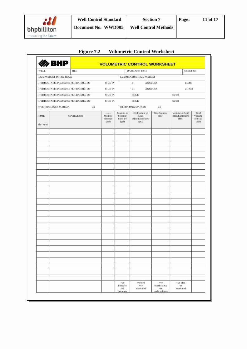
Well Control Standard
Document No. WWD005
Section 7
Well Control Methods
Page: 11 of 17
Figure 7.2 Volumetric Control Worksheet
VOLUMETRIC CONTROL WORKSHEETWELL RIG DATE AND TIME SHEET No
MUD WEIGHT IN THE HOLE LUBRICATING MUD WEIGHT
HYDROSTATIC PRESSURE PER BARREL OF MUD IN x ANNULUS psi/bbl
HYDROSTATIC PRESSURE PER BARREL OF MUD IN x ANNULUS psi?bbl
HYDROSTATIC PRESSURE PER BARREL OF MUD IN HOLE psi/bbl
HYDROSTATIC PRESSURE PER BARREL OF MUD IN HOLE psi/bbl
OVER BALANCE MARGIN psi OPERATING MARGIN psi
TIME
(hr min)
OPERATION........
MonitorPressure
(psi)
Change inMonitorPressure
(psi)
Hydrostatic ofMud
Bled/Lubricated(psi)
Overbalance(psi)
Volume of MudBled/Lubricated
(bbl)
TotalVolumeof Mud
(bbl)
+veincrease
-vedecrease
-ve bled+ve
lubricated
+veoverbalance
-veunderbalance
+ve bled-ve
lubricated
Well Control Standard
Document No. WWD005
Section 7
Well Control Methods
Page: 12 of 17
7.4 Combined Stripping And Volumetric Method
7.4.1 Principle
This is a constant bottomhole pressure method that is used to move pipe through the BOPs with the well under pressure. Example calculations are shown in Appendix 2. While stripping in the hole, BHP is maintained constant by bleeding a small volume of mud from the well to allow for:
• the closed-end volume of pipe run in the hole • possible migration of the influx • displacement of the influx around the BHA as the string is moved into it
7.4.2 Practical Considerations
7.4.2.1 Preparation
Stripping places high stress on the BOP equipment and requires a great deal of coordination by the drill crew. The following should be carefully considered by the DSV before commencing a stripping operation:
a. Accurate measurement of the fluid bled off must be possible, via a stripping tank if available.
b. Competence of the drill crew to perform the stripping operation. c. External condition of the drill pipe. Remove any burrs and drill pipe rubbers. d. Condition of BOPs (rams, annulars, pressure regulators). e. Annular preventer closing pressure must be capable of adjustment after the preventer is
closed. f. Accuracy of pressure gauges. g. Anticipation of influx migration. h. Preparation of stripping worksheet (see Figure 7.3).
7.4.2.2 Choice of Preventer
The annular preventer is usually used because it involves less risk than combination stripping. It is preferred for the following reasons:
• The procedure is relatively simple. • Only the annular element in the BOP is subjected to wear. • On a floating rig the upper annular is used and can be replaced without pulling the BOP
stack.
In practice the surface pressure determines whether the annular can be used. Surface pressures should be reduced by circulating the influx out, bullheading or use of the volumetric method depending on the position of the kick in the annulus and the position of the drill pipe.
Well Control Standard
Document No. WWD005
Section 7
Well Control Methods
Page: 13 of 17
7.4.2.3 Measurement of Volumes and Pressures
Accurate measurement of fluid volumes and pressures is crucial to the success of the stripping operation. Constant bottomhole pressure can only be maintained by close attention to surface measurements.
7.4.2.4 Effect of Adding Pipe
If drill pipe is stripped into the well without bleeding off mud, pressure in the well rises because pipe is forced into a closed system. The effect of this is to increase bottomhole pressure and lead to possible formation fracture and further influxes. Therefore for each stand of pipe stripped-in a volume of mud equivalent to the pipe capacity plus the metal volume of the drill pipe and tool joints must be bled-off. The stand should be filled with mud at each connection after stripping-in.
The displacement volume should preferably be bled-off while the pipe is being stripped-in.
7.4.2.5 Effect of Influx Migration
If the influx is gas that is migrating, the surface pressure will tend to rise even if the correct amount of fluid is bled-off. If migration is suspected then additional fluid must be bled-off by the volumetric method, maintaining the choke pressure constant.
7.4.2.6 Effect of Entering the Influx
When the BHA is run into the influx a large reduction in bottomhole pressure will occur as the height of the influx is increased. The loss of hydrostatic head anticipated should be calculated and a corresponding additional backpressure added to the allowable choke pressure as in the volumetric method at the start of the stripping operation. Adding this pressure increment at the commencement of stripping avoids having to continually estimate the relative position of the BHA versus influx, during stripping.
7.4.2.7 Assumptions
The stripping procedure is simplified by making the following assumptions:
• The influx remains as a discrete volume and is not strung out in the well bore. • The influx is always assumed to occupy an annular space equivalent to the DC/OH annulus
since this is the smallest annular space. When the bit has returned to the bottom of the hole there will be an additional backpressure acting equivalent to the difference in height and corresponding head of influx across the drill collars and the drill pipe.
Well Control Standard
Document No. WWD005
Section 7
Well Control Methods
Page: 14 of 17
7.4.3 Combined Stripping and Volumetric Kill Procedure
7.4.3.1 Shut-In and Initial Calculation 1. Close-in the well. Record shut-in pressures and influx volume. Calculate the height and
gradient of the influx. After closed-in pressures have stabilised, record pressures at regular intervals.
2. Install drill pipe dart. Allow to fall until it seats in the dart sub. Check that dart has landed by bleeding-off 1 bbl of mud from the drill pipe. Install a gray valve if the dart has failed to seat.
3. Prepare the Stripping Worksheet (see Figure 7.3) using the following formulae: a. Calculate the hydrostatic pressure per barrel of mud for the various capacities.
Equivalent hydrostatic = (0.052)(MW) pressure per barrel Capacity bbl
psi
Where: Capacity = capacity of DC/OH annulus or openhole (bbl/ft) MW = mud weight (ppg)
b. Calculate the volume of mud displaced by the drill pipe (the ‘closed end displacement
volume’). This can be calculated using tables or by the following formula (does not including tool joint external upset volume):
Volume of mud displaced = (0.000972)(DP)2
bbl/ft
Where: DP = drill pipe outside diameter (in)
c. Calculate the entering influx margin, Ps
.
Ps
= (0.052)(MW-IW)(V/C1 - V/C2) psi
Where: IW = influx density (ppg) V = influx volume (bbl) C1 = DC/OH capacity (bbl/ft) C2 = open hole capacity (bbl/ft)
d. Select the overbalance margin, Pw
(this value should be between 50 and 200 psi and should be applied throughout the stripping operation).
e. Calculate the pressure the annulus will be allowed to build to while stripping (Pchoke
) where SICP is the initial closed-in casing pressure (psi), from:
Pchoke = SICP + Ps + Pw
Well Control Standard
Document No. WWD005
Section 7
Well Control Methods
Page: 15 of 17
7.4.3.2 Stripping into the Hole 1. Reduce the annular closing pressure sufficiently to allow pipe to move without leakage. 2. Strip the first stand into the hole, running slowly to avoid surging the formation. Strip in
additional pipe until the closed-in annulus pressure has built to Pchoke
3. Once the annulus pressure has reached P.
choke, estimate the length of pipe above the rotary table, and bleed-off the volume of mud corresponding to the remaining pipe still above the rotary (as calculated in 7.4.3.1 Step 3b) while maintaining constant choke pressure Pchoke
4. Repeat Step 3 for subsequent stands, bleeding-off mud to compensate for stripped pipe while maintaining constant choke pressure P
and as the remainder of the stand is stripped-in.
choke
• If the annulus pressure is greater than P, until the pipe is back on bottom.
choke after bleeding-off the correct mud volume, the influx is migrating, and a further mud volume increment must be bled-off at the same constant choke pressure. The volume increment is calculated as in 7.4.3.1 Step 3a. This new annulus pressure is now Pchoke
5. Perform a conventional kill procedure (see Section 7.2). .
7.4.4 Alternative combined volumetric and stripping procedure
A variation of the procedure in Section 7.4.3 is to bleed off a volume increment at the end of each stripped stand that is in addition to the closed end displacement. The additional volume is denoted ∆V and is equivalent to the overbalance margin Pw
.
Where: ∆V = (Pw)(C1) MW
bbl
The additional overbalance volume bled at the end of each stand automatically allows for influx migration as per the volumetric method. If a stripping tank is available, the ∆V volumes bled off are drained into the stripping tank at the end of each stand stripped-in while keeping the closed end displacement volumes bled-off into the trip tank. This allows the two volumetric aspects of the operation to be more easily accounted for.
When both the closed end displacement volumes and the ∆V volumes have been bled-off, the choke is closed and the annulus pressure allowed to rise by Pw
This process is repeated until the pipe is on bottom and a conventional kill procedure can be performed.
, by virtue of stripping the next stand in.
This alternative method is more complicated and depends on the existence of a stripping tank on the rig. It also requires more coordination at the rig-site and a longer communication chain during the operation. However some crews may be familiar with this method if the Drilling Contractor has adopted it.
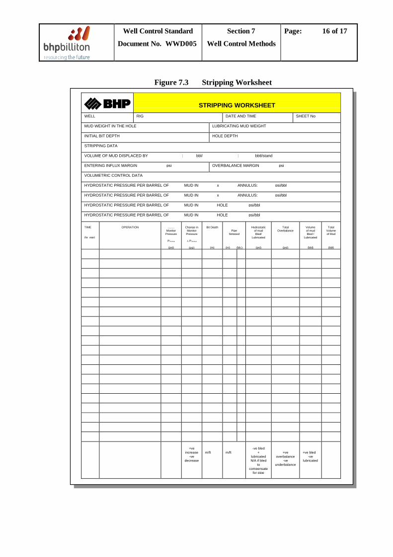
Well Control Standard
Document No. WWD005
Section 7
Well Control Methods
Page: 16 of 17
Figure 7.3 Stripping Worksheet
STRIPPING WORKSHEETWELL RIG DATE AND TIME SHEET No
MUD WEIGHT IN THE HOLE LUBRICATING MUD WEIGHT
INITIAL BIT DEPTH HOLE DEPTH
STRIPPING DATA
VOLUME OF MUD DISPLACED BY : bbl/ : bbtl/stand
ENTERING INFLUX MARGIN psi OVERBALANCE MARGIN psi
VOLUMETRIC CONTROL DATA
HYDROSTATIC PRESSURE PER BARREL OF MUD IN x ANNULUS: psi/bbl
HYDROSTATIC PRESSURE PER BARREL OF MUD IN x ANNULUS: psi/bbl
HYDROSTATIC PRESSURE PER BARREL OF MUD IN HOLE psi/bbl
HYDROSTATIC PRESSURE PER BARREL OF MUD IN HOLE psi/bbl
TIME
(hr min)
OPERATION ........Monitor
Pressure
Pchoke
(psi)
Change inMonitor
Pressure
∆ Pchoke
(psi)
Bit Depth
(m)
PipeStripped
(m) (bb;)
Hydrostaticof mudBled/
Lubricated
(psi)
TotalOverbalance
(psi)
Volumeof mudBled /
Lubricated
(bbl)
TotalVolumeof Mud
(bbl)
+veincrease
-vedecrease
m/ft m/ft-ve bled
+lubricatedN/A if bled
tocompensate
for pipe
+veoverbalance
-veunderbalance
+ve bled-ve
lubricated
Well Control Standard
Document No. WWD005
Section 7
Well Control Methods
Page: 17 of 17
7.5 Bullheading
Bullheading is a method whereby an influx is pumped back into the formation.
Although bullheading is a routine technique used in producing well workovers for displacing hydrocarbons from the completion tubulars with a kill weight fluid, the method is not routine for well control in drilling operations, because there is no way of controlling where, in the open hole, fluids are displaced.
However, the technique may be useful in the following circumstances:
1. There is a suspected string washout at or near surface. 2. Calculation shows that the MAASP would be exceeded during a conventional circulating
kill method, and conditions are such that the pressure exerted at the shoe during bullheading are less than those calculated for a conventional circulating kill. These conditions would normally only be satisfied in the following cases: • The influx is too large to be safely handled through the surface equipment. • The influx is suspected to contain a huge concentration of H2
• A combination of kick and losses prevents the use of a controlled circulating kill method. S.
The rating of surface equipment, the burst design safety factor should determine / limit the bullheading pressure, the formation strength and the likely consequences of initiating a fracture must be taken into account when considering a bullheading operation.
Well Control Standard
Document No. WWD005
Section 8
Shallow Gas
Page: 1 of 8
TABLE OF CONTENTS
8.1 Introduction................................................................................................................................2
8.2 Probability and Risk ..................................................................................................................2
8.3 Shallow Gas Control Procedures .............................................................................................2
8.4 Pre-Spud Rig Preparation ........................................................................................................6
8.5 General Drilling Guidelines .....................................................................................................6
8.6 Moving Off Location.................................................................................................................7
Well Control Standard
Document No. WWD005
Section 8
Shallow Gas
Page: 2 of 8
8.1 Introduction
Shallow gas is defined as any hydrocarbon-bearing zone that may be encountered at a depth close to the surface or mudline. Generally it is not possible to close-in and contain a gas influx from a shallow zone because weak formation integrity will lead to breakdown and broaching to surface/mudline. This situation is particularly hazardous when drilling from a fixed installation or jack-up.
Shallow gas-bearing zones are usually normally pressured though the effective increase in pore pressure due to gas gradient can lead to underbalance when a shallow gas zone is first penetrated.
8.2 Probability and Risk
The identification and avoidance of shallow gas must be a principal objective in well planning and site survey procedures. All Drilling Programmes will contain a clear statement on the probability and risk of encountering shallow gas. This shall be based on a suitable shallow seismic survey and interpretation, together with offset geological and drilling data. If a suitable gas-free zone cannot be identified, written approval from the Drilling Manager is required before proceeding with spudding-in on an expected gas-prone location.
8.3 Shallow Gas Control Procedures
Procedures for dealing with the shallow gas hazard onshore, on floaters and on bottom-supported rigs are summarised in Figures 8.1-8.3.
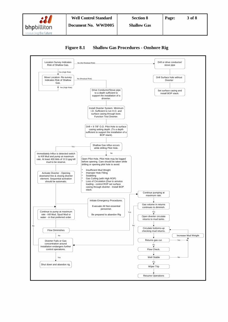
Well Control Standard
Document No. WWD005
Section 8
Shallow Gas
Page: 3 of 8
Figure 8.1 Shallow Gas Procedures - Onshore Rig
Yes
Location Survey IndicatesRisk of Shallow Gas.
Drill or drive conductor/stove pipe
Move Location- Re-surveyIndicates Risk of Shallow
Gas.
Drive Conductor/Stove pipeto a depth sufficient to
support the installation of adriverter.
Install Diverter System. MinimumI.D. Sufficient to run H.O. andsurface casing through bore.
Function Test Diverter.
Drill < 9 7/8" O.D. Pilot Hole to surfacecasing setting depth. (To a depth
sufficient to support the installation of aBOP stack).
Shallow Gas influx occurswhile drilling Pilot Hole.
Open Pilot Hole, Pilot Hole may be loggedbefore opening. Care should be taken whiledrilling or opening pilot hole to avoid:
* Insufficient Mud Weight* Improper Hole Filling* Swabbing* Gas Cutting (with High ROP)* Loss of Circulation (Due to annulus
loading - control ROP set surfacecasing through diverter - Install BOPstack.
Initiate Emergency Procedures.
Evacuate All Non-essentialpersonnel.
Be prepared to abandon Rig
Immediately Influx is detected switchto Kill Mud and pump at maximum
rate. At least 400 bbls of 12.0 ppg killmud to be reserve.
Activate Diverter - Openingdownwind line & closing diverterelement. Sequential activation
should be automatic.
Continue to pump at maximumrate - Kill Mud, Spud Mud or
water - in that preferred order.
Flow Diminishes
Diverter Fails or Gasconcentration around
installation endangers furthercontrol operations.
Shut down and abandon rig.
No
No
Yes
No
Yes (High Risk)
No (Residual Risk)
Yes (High Risk)
No (No Residual Risk)
Drill Surface hole withoutDiverter
Set surface casing andinstall BOP stack.
Continue pumping atmaximum rate.
Gas volume in returnscontinues to diminish.
Open diverter circulatereturns to mud tanks.
Circulate bottoms-upchecking mud returns.
Returns gas cut.
Flow Check.
Well Stable
Wiper Trip
Resume Operations
Increase Mud Weight
Yes
No
Yes
No
Yes
Yes
No
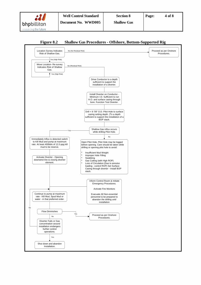
Well Control Standard
Document No. WWD005
Section 8
Shallow Gas
Page: 4 of 8
Figure 8.2 Shallow Gas Procedures - Offshore, Bottom-Supported Rig
Yes
Location Survey IndicatesRisk of Shallow Gas.
Proceed as per OnshoreProcedures.
Move Location- Re-surveyIndicates Risk of Shallow
Gas.
Drive Conductor to a depthsufficient to support theinstallation of a diverter.
Install Diverter on Conductor -Minimum I.D. Sufficient to run
H.O. and surface casing throughbore. Function Test Diverter.
Drill < 9 7/8" O.D. Pilot Hole to surfacecasing setting depth. (To a depth
sufficient to support the installation of aBOP stack.
Shallow Gas influx occurswhile drilling Pilot Hole.
Open Pilot Hole, Pilot Hole may be loggedbefore opening. Care should be taken whiledrilling or opening pilot hole to avoid:
* Insufficient Mud Weight* Improper Hole Filling* Swabbing* Gas Cutting (with High ROP)* Loss of Circulation (Due to annulus
loading - control ROP) Set SurfaceCasing through diverter - Install BOPstack.
Inform Control Room & InitiateEmergency Procedures.
Activate Fire Monitors
Evacuate All Non-essentialpersonnel & be prepared to
abandon the drilling unit/installation
Proceed as per OnshoreProcedures.
Immediately Influx is detected switchto Kill Mud and pump at maximum
rate. At least 400bbls of 12.0 ppg killmud to be reserve.
Activate Diverter - Openingdownwind line & closing diverter
element.
Continue to pump at maximumrate - Kill Mud, Spud Mud or
water - in that preferred order.
Flow Diminishes
Diverter Fails or Gasconcentration aroundinstallation endangers
further controloperations.
Shut down and abandonInstallation.
No
YesNo
Yes
No
Yes (High Risk)
No (Residual Risk)
Yes (High Risk)
No (No Residual Risk)
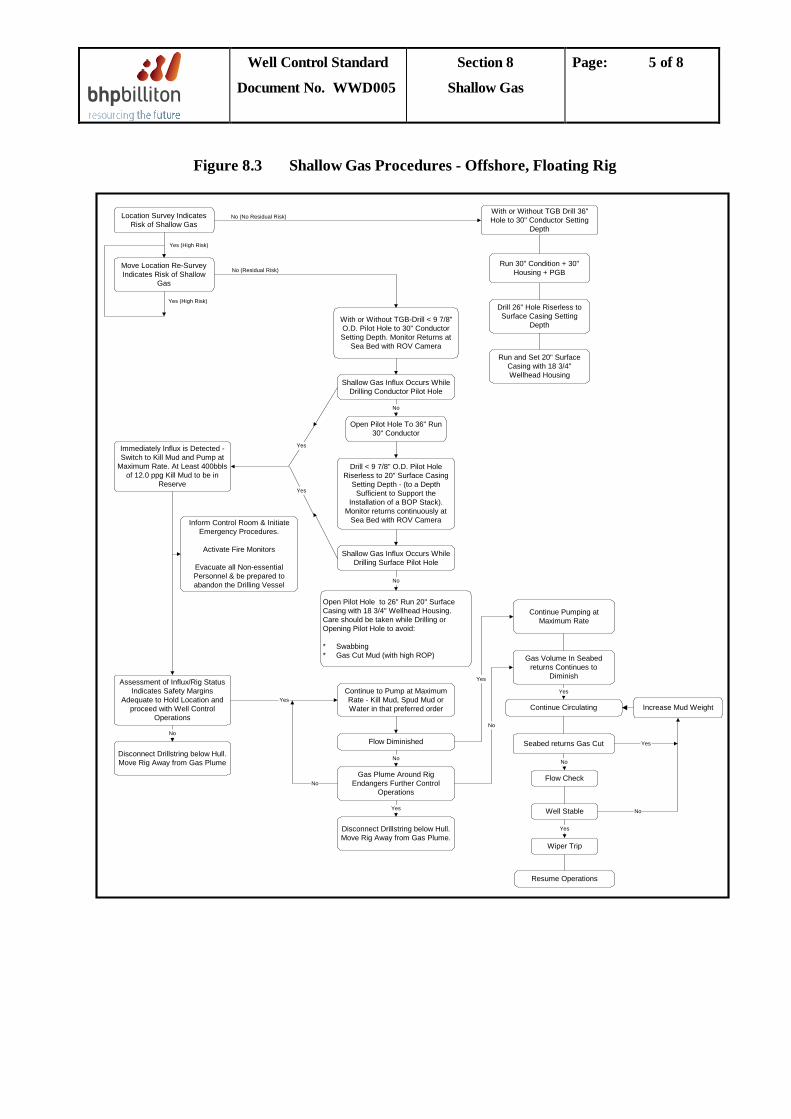
Well Control Standard
Document No. WWD005
Section 8
Shallow Gas
Page: 5 of 8
Figure 8.3 Shallow Gas Procedures - Offshore, Floating Rig
Location Survey IndicatesRisk of Shallow Gas
Move Location Re-SurveyIndicates Risk of Shallow
Gas
With or Without TGB-Drill < 9 7/8"O.D. Pilot Hole to 30" ConductorSetting Depth. Monitor Returns at
Sea Bed with ROV Camera
Shallow Gas Influx Occurs WhileDrilling Conductor Pilot Hole
Open Pilot Hole To 36" Run30" Conductor
Drill < 9 7/8" O.D. Pilot HoleRiserless to 20" Surface Casing
Setting Depth - (to a DepthSufficient to Support the
Installation of a BOP Stack).Monitor returns continuously at
Sea Bed with ROV Camera
Shallow Gas Influx Occurs WhileDrilling Surface Pilot Hole
Open Pilot Hole to 26" Run 20" SurfaceCasing with 18 3/4" Wellhead Housing.Care should be taken while Drilling orOpening Pilot Hole to avoid:
* Swabbing* Gas Cut Mud (with high ROP)
Continue to Pump at MaximumRate - Kill Mud, Spud Mud orWater in that preferred order
Flow Diminished
Gas Plume Around RigEndangers Further Control
Operations
Disconnect Drillstring below Hull.Move Rig Away from Gas Plume.
Immediately Influx is Detected -Switch to Kill Mud and Pump at
Maximum Rate. At Least 400bblsof 12.0 ppg Kill Mud to be in
Reserve
Inform Control Room & InitiateEmergency Procedures.
Activate Fire Monitors
Evacuate all Non-essentialPersonnel & be prepared toabandon the Drilling Vessel
Assessment of Influx/Rig StatusIndicates Safety Margins
Adequate to Hold Location andproceed with Well Control
Operations
Disconnect Drillstring below Hull.Move Rig Away from Gas Plume
With or Without TGB Drill 36"Hole to 30" Conductor Setting
Depth
Run 30" Condition + 30"Housing + PGB
Drill 26" Hole Riserless toSurface Casing Setting
Depth
Run and Set 20" SurfaceCasing with 18 3/4"Wellhead Housing
No
No
No
Yes
Yes
Yes
No (No Residual Risk)
No (Residual Risk)
Yes (High Risk)
Yes (High Risk)
Yes
No
No
Continue Pumping atMaximum Rate
Gas Volume In Seabedreturns Continues to
Diminish
Continue Circulating
Seabed returns Gas Cut
Flow Check
Well Stable
Wiper Trip
Resume Operations
No
Yes
No
Yes
Yes
Increase Mud Weight
No
Yes
Well Control Standard
Document No. WWD005
Section 8
Shallow Gas
Page: 6 of 8
8.4 Pre-Spud Rig Preparation a. For floating rigs the anchor chain pre tension shall be specified. The minimum move
capability shall be based on the chain available in the lockers. The status of winch locks, brakes, clutch and motors shall be checked. Water spray system shall be ready and the hatches and doors closed.
b. A hot work prohibition shall be enforced until the shallow gas risk is passed. POB shall be
kept at a minimum, with responsible persons identified and duties allocated at a pre spud meeting that shall address all aspects of the shallow gas hazard.
c. Pull off, diverter and safety drills shall be conducted. d. The standby and anchor handling boats shall be in attendance at all times. Weather and
current shall be monitored closely. e. A moonpool and sea surface watcher shall be posted. f. The mud pumps shall be fitted with the largest available liner size. g. Emergency evacuation plans and both offshore and onshore management response shall be
rehearsed prior to spud. h. All rig gas sensors must be working and correctly positioned.
8.5 General Drilling Guidelines a. Potential shallow gas zones shall be drilled in daylight hours only. b. Consideration should be given to drilling a test hole to a depth 10m deeper than the casing
string after which normal well control measures are programmed. The test hole should be as small as practical and the BHA shall include a float valve. If test hole is a pilot for the main hole, the BHA size and design must consider deviation and subsequent hole opening. The major advantages of a small test hole are:
• Lesser degree of gas cutting. • Greater chance of bridging in a gas flow situations. • Marginally less initial inflow rate. • Greater chance of dynamically killing a gas flow due to increased ECD effect at high
pump rate. c. All top hole sections drilled from floating rigs shall be drilled riserless.
d. Drillships shall not be used in shallow gas prone areas if the water depth is less than 200m
(650 ft). e. On jack-ups, consideration should be given to drilling a test hole in floating or near floating
mode if weather and sea conditions permit.
Well Control Standard
Document No. WWD005
Section 8
Shallow Gas
Page: 7 of 8
f. The ROP shall be controlled to avoid overloading the annulus with cuttings and inducing losses.
g. All losses shall be cured prior to drilling ahead. h. Pump pressure shall be closely monitored and all connections shall be flow checked. i. Pipe should be pumped out of hole at a moderate rate to prevent swabbing. j. Test hole and pilot hole BHAs should be slick. k. Consideration shall be given to using an LWD GR/Resistivity tool to identify gas zones. l. ROV shall be deployed on sub-sea wells during conductor and surface hole sections,
continuously observing for signs of gas while drilling. ROV should be used to monitor any anomalous flow checks.
8.6 Moving Off Location
If flow continues after pumping all of the kill mud, the rig should be moved off location. Although it is preferable to remove the string from the hole prior to moving, the safety of the installation and its crew are the main priority. The following are suggested courses of action that can be taken depending on circumstances:
a. Pull the string above the seabed, then move the rig. b. Move the rig partially off location and then attempt to pull or drop the string. c. Drop the string immediately and move off. d. Move the rig off immediately and allow the string to fracture. In the case of a. above, proceed as follows: 1. Close the lower Kelly cock or TDS lower safety valve, remove Kelly/TDS. 2. If the float valve is not holding insert drop-in dart, make up/TDS. 3. Pressure behind the Kelly cock or lower safety valve, then open the valve. This prevents the
dart being pushed into the gooseneck, in the event of flow up the drill string. 4. Chase the dart with kill mud until seated and latched. 5. Check for flow in the string. Remove/TDS. 6. Pull bit above the seabed. Move rig. In the case of b. above, then: 1. Close the lower Kelly cock or top drive system (TDS) lower safety valve, remove/TDS. 2. If the float valve is not holding insert drop-in dart, make up/TDS. 3. Pressure behind the Kelly cock or lower safety valve, then open the valve. This prevents the
dart being pushed into the gooseneck, in the event of flow up the drill string. 4. Chase the dart with kill mud until seated and latched. 5. Check for flow in the string. Remove/TDS.
Well Control Standard
Document No. WWD005
Section 8
Shallow Gas
Page: 8 of 8
6. Pull back enough pipe so that when the string is dropped, the top of the pipe is clear of the hull when the bit hits bottom.
7. With pipe hanging in the elevators, attach tugger line to the elevator latch and release the pipe.
In the case of c. above, then: 1. Close lower Kelly cock, remove Kelly. 2. With pipe hanging in the elevators attach tugger line to the elevator latch and release the
pipe.
or, for a TDS: 1. Close lower safety valve. 2. Re-set pipe handler and break the connection between upper and lower safety valves. 3. Spin out connection with TDS motor in reverse to release the pipe.
Note: When releasing the drill string the elevators should be lowered as near as possible to the rotary table prior to unlatching the drill string. For safety considerations be aware that when the drill string weight is removed from the elevator - the blocks may recoil a considerable distance.
In the case of d. above, be aware of the danger this threatens to personnel working in the moonpool and rig floor areas and the potential damage to the hull, moonpool and rig floor equipment.
Well Control Standard
Document No. WWD005
Section 9
Well Control Equipment
Page: 1 of 31
TABLE OF CONTENTS
9.1 BOP Stacks .......................................................................................................................................2 9.1.1 Subsea BOP Stacks .............................................................................................................2
9.1.1.1 Moored Drilling Rigs ...................................................................................................2 9.1.1.2 Dynamically Positioned Drilling Rigs .........................................................................3
9.1.2 Subsea Stack Emergency Systems ......................................................................................6 9.1.3 Surface BOP Stacks ............................................................................................................6
9.2 Mud Gas Separator (Poorboy Degasser) ..........................................................................................7 9.2.1 Definition of Terms .............................................................................................................7 9.2.2 Discussion on Mud Gas Separator (MGS) Design ............................................................8 9.2.3 Mud Gas Separator Capacity - Design and Assessment ....................................................9
9.3 Accumulator Volume Requirements .............................................................................................. 12 9.4 BOP System Testing ...................................................................................................................... 15
9.4.1 General Testing Practices ............................................................................................... 15 9.4.2 Deadman – Surface Test ................................................................................................ 16 9.4.3 Hydril Autoshear – Surface Test .................................................................................... 18 9.4.4 Plunger Type Autoshear – Surface Test ......................................................................... 19 9.4.5 EDS - Surface Test ......................................................................................................... 20 9.4.6 ROV Function - Surface Test ........................................................................................ 23 9.4.7 ROV Operation if BOP Functions (Subsea) .................................................................. 25 9.4.9 Stack Testing Procedure ................................................................................................. 29 9.4.10 Diverter System Testing ................................................................................................. 30 9.4.11 Accumulator Drill .......................................................................................................... 30
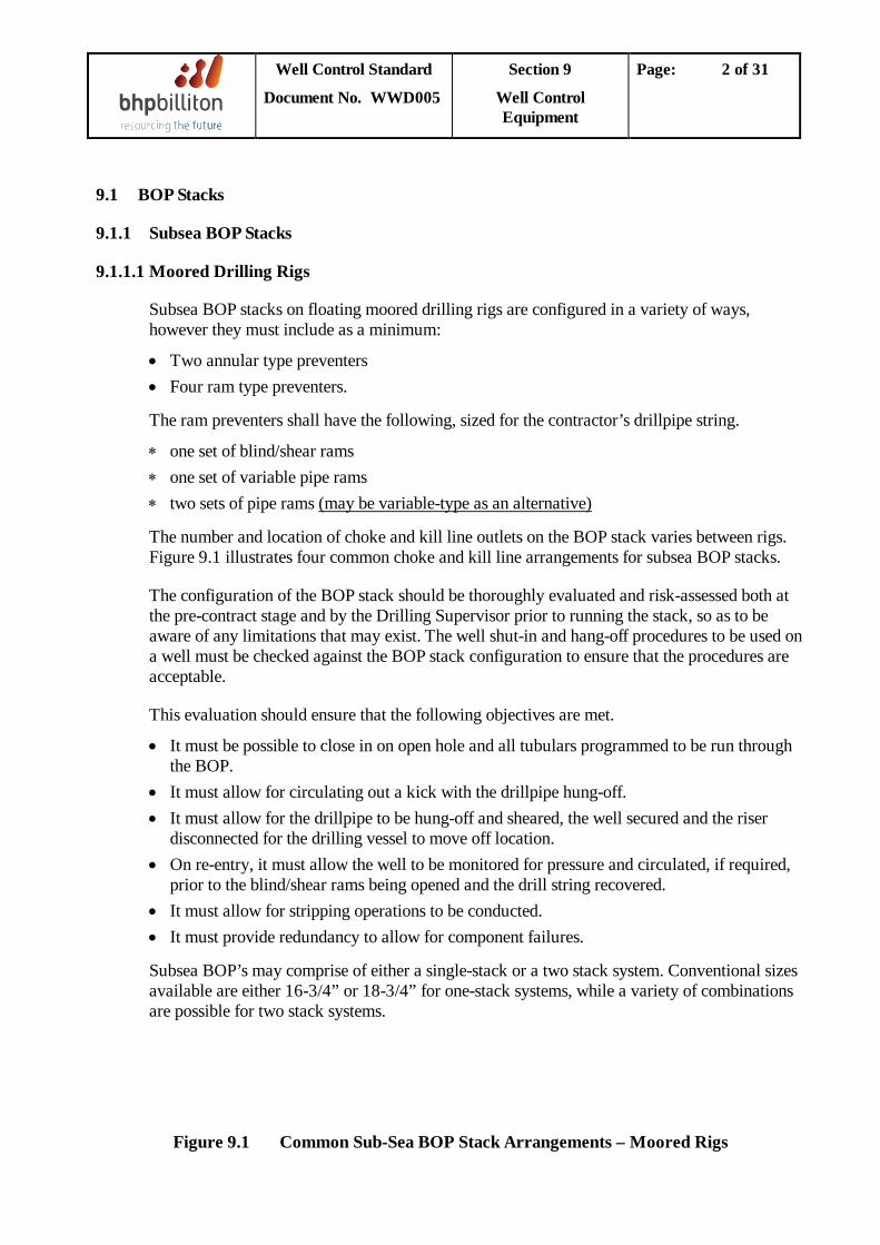
Well Control Standard
Document No. WWD005
Section 9
Well Control Equipment
Page: 2 of 31
9.1 BOP Stacks
9.1.1 Subsea BOP Stacks
9.1.1.1 Moored Drilling Rigs
Subsea BOP stacks on floating moored drilling rigs are configured in a variety of ways, however they must include as a minimum:
• Two annular type preventers • Four ram type preventers.
The ram preventers shall have the following, sized for the contractor’s drillpipe string.
∗ one set of blind/shear rams ∗ one set of variable pipe rams ∗ two sets of pipe rams
The number and location of choke and kill line outlets on the BOP stack varies between rigs. Figure 9.1 illustrates four common choke and kill line arrangements for subsea BOP stacks.
(may be variable-type as an alternative)
The configuration of the BOP stack should be thoroughly evaluated and risk-assessed both at the pre-contract stage and by the Drilling Supervisor prior to running the stack, so as to be aware of any limitations that may exist. The well shut-in and hang-off procedures to be used on a well must be checked against the BOP stack configuration to ensure that the procedures are acceptable.
This evaluation should ensure that the following objectives are met.
• It must be possible to close in on open hole and all tubulars programmed to be run through the BOP.
• It must allow for circulating out a kick with the drillpipe hung-off. • It must allow for the drillpipe to be hung-off and sheared, the well secured and the riser
disconnected for the drilling vessel to move off location. • On re-entry, it must allow the well to be monitored for pressure and circulated, if required,
prior to the blind/shear rams being opened and the drill string recovered. • It must allow for stripping operations to be conducted. • It must provide redundancy to allow for component failures.
Subsea BOP’s may comprise of either a single-stack or a two stack system. Conventional sizes available are either 16-3/4” or 18-3/4” for one-stack systems, while a variety of combinations are possible for two stack systems.
Figure 9.1 Common Sub-Sea BOP Stack Arrangements – Moored Rigs
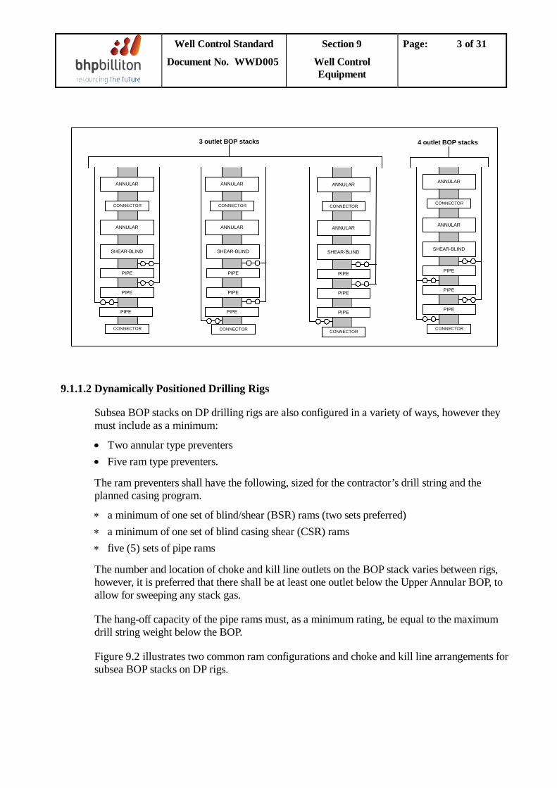
Well Control Standard
Document No. WWD005
Section 9
Well Control Equipment
Page: 3 of 31
ANNULAR
CONNECTOR
ANNULAR
SHEAR-BLIND
PIPE
CONNECTOR
PIPE
PIPE
ANNULAR
CONNECTOR
ANNULAR
SHEAR-BLIND
PIPE
CONNECTOR
PIPE
PIPE
ANNULAR
CONNECTOR
ANNULAR
SHEAR-BLIND
PIPE
CONNECTOR
PIPE
PIPE
ANNULAR
CONNECTOR
ANNULAR
SHEAR-BLIND
PIPE
CONNECTOR
PIPE
PIPE
3 outlet BOP stacks 4 outlet BOP stacks
9.1.1.2 Dynamically Positioned Drilling Rigs
Subsea BOP stacks on DP drilling rigs are also configured in a variety of ways, however they must include as a minimum:
• Two annular type preventers • Five ram type preventers.
The ram preventers shall have the following, sized for the contractor’s drill string and the planned casing program.
∗ a minimum of one set of blind/shear (BSR) rams (two sets preferred) ∗ a minimum of one set of blind casing shear (CSR) rams ∗ five (5) sets of pipe rams
The number and location of choke and kill line outlets on the BOP stack varies between rigs, however, it is preferred that there shall be at least one outlet below the Upper Annular BOP, to allow for sweeping any stack gas.
The hang-off capacity of the pipe rams must, as a minimum rating, be equal to the maximum drill string weight below the BOP.
Figure 9.2 illustrates two common ram configurations and choke and kill line arrangements for subsea BOP stacks on DP rigs.
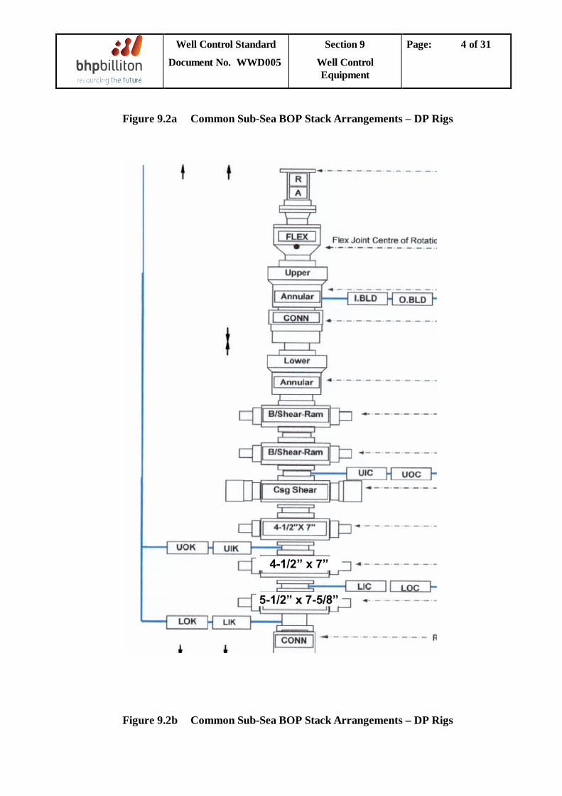
Well Control Standard
Document No. WWD005
Section 9
Well Control Equipment
Page: 4 of 31
Figure 9.2a Common Sub-Sea BOP Stack Arrangements – DP Rigs
Figure 9.2b Common Sub-Sea BOP Stack Arrangements – DP Rigs
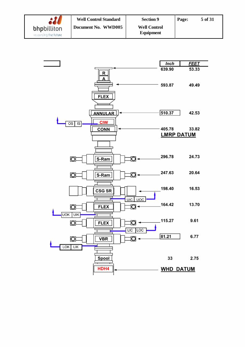
Well Control Standard
Document No. WWD005
Section 9
Well Control Equipment
Page: 5 of 31
Well Control Standard
Document No. WWD005
Section 9
Well Control Equipment
Page: 6 of 31
9.1.2 Subsea Stack Emergency Systems An acoustic emergency backup system may be installed on the BOP stack, to actuate selected BOP functions when primary control system contact with the BOP stack is lost. However, such systems have been used by BHPB Drilling in the past but did not perform satisfactorily. An acoustic emergency backup system should only be used where (a) the rig has an acceptable performance record for the emergency system and / or (b) where it is a requirement of local legislation The systems operate by using acoustic signals emitted on location, either from the rig or off location from a boat or helicopter, transmitted through the water to either or both hydrophones located on the BOP stack. The acoustic signals are converted to electrical signals, which actuate solenoid pilot valves. The solenoid pilot valves send an hydraulic signal to actuate a control valve that allows fluid to flow from an accumulator bank to the function. The system is connected to the primary control system through shuttle valves. The acoustic backup system is similar to the electro-hydraulic systems except that the signals are sent acoustically rather than electrically.
9.1.3 Surface BOP Stacks
Surface BOP stacks are configured in a variety of ways, however they should include both an annular type preventer and ram type preventers, irrespective of size and pressure rating.
The number and location of choke and kill line outlets on surface BOP stack varies between rigs. Configurations of land and offshore surface BOP stacks should be thoroughly evaluated and risk-assessed both at the pre-contract stage and by the Drilling Supervisor prior to spud, to be aware of any limitations which may exist.
The evaluation should ensure that it is possible to close in on open hole and on all tubulars programmed to be run through the BOP, including casing strings and liners, that stripping operations can be conducted and that redundancy is provided to allow for component failures.
Conventional sizes and ratings available are generally a function of the rig’s depth rating and common casing sizes in the area where the rig usually operates. Nominal 20” 2M/3M stacks are common for top-hole drilling, with 13.3/8” and 11” 5M, 10M and 15M. All offshore surface BOP’s must be fitted with a blind / shear ram. Land BOP’s rated at less than 10,000 psi may be fitted with a blind ram without shear capability, but only if the rig is contracted for a short-term campaign, is equipped with such rams as standard, obtaining a replacement stack with shear capability would be impracticable and after a risk assessment confirms that the residual risks are acceptable. Choke and kill lines should be dual-purpose, by preference, each with two full-bore valves of which one should be hydraulic-operated. Choke and kill lines should allow circulation beneath the blind / shear rams. All ram-type preventers should be fitted with ram locks.
It should be noted that some types of shear ram are not capable of shearing higher grade drill pipe and all casing sizes and materials. Shear ram capabilities should be evaluated as part of any rig inspection or hazard assessment conducted, to determine any deficiencies.
Well Control Standard
Document No. WWD005
Section 9
Well Control Equipment
Page: 7 of 31
9.2 MUD GAS SEPARATOR (POORBOY DEGASSER)
The purpose of the mud gas separator (sometimes referred to as the “poorboy degasser”) is to remove free gas from the mud leaving the choke manifold, before the de-gassed mud is routed back to the mud treatment skid. Often mud gas separators are undersized, which restricts the maximum circulation rate when an influx is circulated from a well.
There is no industry standard overall design requirement for mud gas separators, though API 12J had been used historically. Because of the inadequacies in design of such separators, legislation was introduced in the UK to enforce minimum standards of design (UK Health and Safety Executive Safety Notice 11/90 - referred to a “PED 11/90” below). Typical arrangements for mud gas separators are shown in Figure 9.4. A discussion on design aspects of mud gas separators follows in section 9.2.2 below. Guidance on design assessment and acceptable standards of mud gas separators is provided in section 9.2.3 below.
Prior to contracting any rig, the MGS capacity should be calculated at various flow rates, to determine the design suitability. The test that should be applied is that described in 9.2.3 below.
9.2.1 Definition of Terms
• Separation Capacity The separation capacity can be defined as being the rate of delivery of mud and gas to the separator at which the mud carry-over rate becomes significant. Once the separation capacity is exceeded then a significant quantity of mud is carried into the vent line. For a mud gas separator (MGS) the separator performance and its capacity is dependent on two main factors, namely the separator design and fluid / kick properties (i.e. separator diameter, inlet pipe diameter, height between inlet and gas outlet).
• Blowdown Capacity The mud seal blowdown capacity can be defined as the gas vent rate at which the vent line pressure drop equals the hydrostatic head due to the mud seal. The blowdown capacity is therefore dependent upon the vent line diameter, vent line length, the mud seal height and also the mud and gas densities. The separator pressure at which a blowdown occurs is totally dependent on the hydrostatic head available in the mud seal.
• Safe Operating Capacity When circulating out a kick, there must be an appropriate safety factor between the operating capacity and the operating limits (the separation capacity and the blowdown capacity) of the MGS. This is called the safe operating capacity. The safe operating capacity is then used to establish the maximum allowable slow circulation rate for the design maximum casing pressure. The safe operating capacity must be lower than the separation capacity to reduce the effect of mud carry-over on vent line pressure drop, and is given by either the separation or the blowdown capacity divided by a safety factor. The safe operating capacity can be expressed either as a gas volumetric rate downstream of the choke or a rate of delivery of mud and gas upstream of the choke.
Well Control Standard
Document No. WWD005
Section 9
Well Control Equipment
Page: 8 of 31
• Safety factors Separation capacity safety factor - A value of 1.5 is recommended if the API 12J specification is used for sizing vertical or horizontal gravity separators. A much larger safety factor (2.0) is recommended if the separation capacity is calculated using the liquid carry-over model. Blowdown capacity safety factor - A large safety factor between the MGS blowdown capacity and safe operating capacity is required to allow for any condition that may occur during a kill operating and also to reduce the effect of liquid carry-over on the vent line pressure drop. The Weymouth formula has traditionally been used to size the vent line. This uses the expected gas vent rate and maximum back-pressure which the separator mud seal can withstand (a function of mud seal height and mud weight) to estimate the vent-line pressure drop for any given vent line diameter. A safety factor of 5.0 is recommended if this traditional method for sizing the vent line is used. Alternatively if the AEA method of sizing the vent line is used (see 9.2.3. below) then a safety factor of 3.0 is recommended.
• Recommended Minimum Blowdown Capacity Operating of the choke valve during a kill operation is of particular importance, as the pressure upstream of the choke valve can be large. The higher the pressure upstream of the choke valve, the larger the volume of gas when expanded to near atmospheric conditions, and the operation of the choke valve becomes more critical. It is very important to note that it is the instantaneous gas rate (and mud carry-over rate) that sets the separator pressure. A larger volumetric gas rate passing through the separator for a very short period of time is sufficient to cause blowdown of the mud seal. The recommended minimum blowdown capacity is based on a choke valve discharge area of 0.125 in2
9.2.2 Discussion on Mud Gas Separator (MGS) Design
. The predicted blowdown capacity should be equal to or greater than the recommended minimum blowdown capacity.
The performance of the MGS will control the rate at which a kick can be circulated out of the well. This section discusses the mechanical design of the MGS and the consequence of the design on separators performance.
Separator performance is a function of separator diameter, therefore the choice of diameter will have a significant effect on the separation capacity of the MGS.
The inlet size also plays an important role in defining the separation capacity of a MGS. A small inlet size will maximise the gas from mud separation on entry into the separator. However, with smaller inlet sizes, the proportion of mud entrained as fine droplets in the gas flow increases due to the higher gas velocity in the inlet pipe. For a gas flow of 1 MMscf/D in a 4” pipe, the gas velocity is over 132 ft/sec (at standard conditions). Fine droplets are more readily carried over with the gas, thus adding to the vent line pressure drop and increasing the risk of mud seal blowdown.
Well Control Standard
Document No. WWD005
Section 9
Well Control Equipment
Page: 9 of 31
The inlet device design will influence the performance of the separator. Often baffles are installed to aid the separation process though these can lead to “break-up” of the mud droplets increasing the likelihood of carry-over with the gas thus increasing back pressure.
The vent line pressure drop is highly sensitive to the vent line size and controls the venting capacity for a given mud seal height. The Department of Energy Safety Notice PED 11/90, which is valid for the UK North Sea sector, states that the vent line should not be less than 8” in diameter.
A mud seal is obtained by ensuring a minimum mud hold-up volume within the MGS vessel. PED 11/90 states that the mud seal height should be a minimum of 10’, but preferably 20’. The amount by which the MGS can be pressurised is totally dependent upon the hydrostatic head available in the mud seal.
A siphon breaker is a particularly important design feature if the mud return line is below the separator fluid level elevation. Secondly, the siphon breaker will act as a vent if a blowdown occurs and will reduce the quantity of the mud /explosive gas mixture flowing to the shaker room if such an event should occur. PED 11/90 recommends that the siphon breaker must be present and should be a minimum of 6” diameter; Also, the siphon breaker must not be tied into the main vent line as gas could back-flow from the main vent line to the shaker room.
A low range pressure gauge (0 -7.5 psig) should be installed on the separator and must be clearly visible from the choke control position.
A separate ‘hot mud inlet’, if fitted, will allow for the circulation of gas free mud into the degasser to maintain the fluid level and to ensure that if gas condensate should be flowing into the MGS, the mud seal does not become progressively diluted with condensate, which may reduce the density of liquid in the mud seal and consequently increase the possibility of blowdown. Similarly, if raw gas flows into the MGS the static mud may eventually be carried over into the vent line. A ‘hot mud inlet’ provides a means of maintaining the mud flow and mud seal fluid level in such circumstances.
9.2.3 Mud Gas Separator Capacity - Design and Assessment
• AEA Technology MGS PET Separator Performance Model The algorithms developed by AEA Technology in the UK have been used previously by BHPB to carry out MGS performance analysis for particular rigs involved in Category 1 wells, where the mud gas separator did not meet PED 11/90 requirements.
AEA Technology’s “MGS PET” software is based on an industry-sponsored study that lead to the development of a liquid carry-over model based upon both experimental data and two-phase flow theory. A kick-sensitivity model (kick size; severity) is first used to define casing pressure and two-phase (gas/mud) surface flowrate, which are used as inputs to the separator design model. For any given separator design the AEA algorithm provides the flowrate at which liquid carry-over will occur for any casing pressure (i.e. choke upstream pressure), using a notional 0.125” choke size. Vent line capacity is then determined from the two-phase carry-over model and vent line diameter, in conjunction with a two-phase flow-rate / pressure drop
Well Control Standard
Document No. WWD005
Section 9
Well Control Equipment
Page: 10 of 31
correlation (Lockhart-Martinelli), rather than the traditional simplistic single-phase Weymouth equation for gas only.
• Design Check Guidelines The requirements specified in the UK Health and Safety Executive Safety Notice 11/90 must be used to assess the acceptable dimensions and design details of all equipment associated with the mud gas separator, including the separator itself, for all Category 1 wells. While API 12J may be used, with caution, to size the separation chamber based upon the design safety factors presented in section 9.2.2 above, use of the AEA Technology “MGS PET” algorithm is preferred.
If the dimensions of a particular mud gas separator satisfies the requirements stated in PED 11/90 then further analysis is unnecessary. For those mud gas separators that do not satisfy the PED 11/90 requirements, further analysis of the operating capacity of the mud gas separator system should be performed.
Where any rig used to drill a Category 1 well does meet the requirements for mud gas separator design and operation specified in the UK Health and Safety Executive Safety Notice 11/90 (summarised in Appendix 3), Worldwide Drilling’s preferred contractor AEA Technology should be requested to conduct a design check on behalf of the Regional Drilling Department.
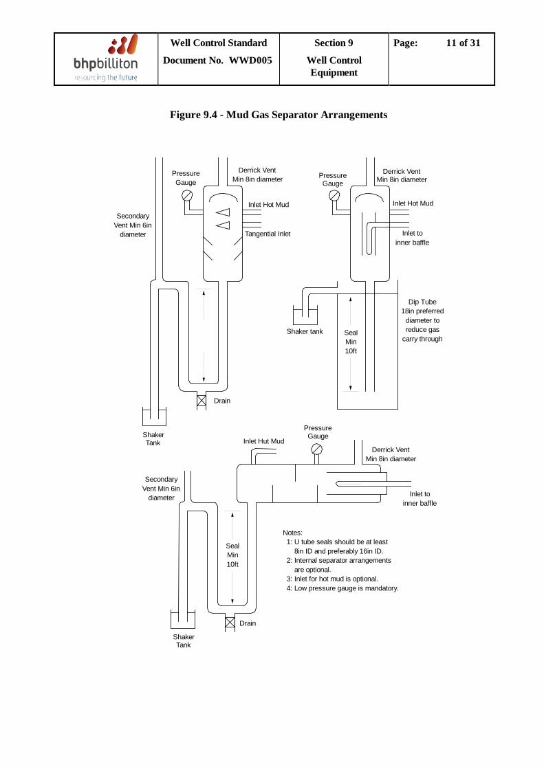
Well Control Standard
Document No. WWD005
Section 9
Well Control Equipment
Page: 11 of 31
Figure 9.4 - Mud Gas Separator Arrangements
SecondaryVent Min 6in
diameter
PressureGauge
Derrick VentMin 8in diameter
Inlet Hot Mud
Tangential Inlet
PressureGauge
Derrick VentMin 8in diameter
Inlet Hot Mud
Inlet toinner baffle
Shaker tank SealMin10ft
Dip Tube18in preferred
diameter toreduce gas
carry through
Derrick VentMin 8in diameter
PressureGauge
Drain
ShakerTank Inlet Hut Mud
SecondaryVent Min 6in
diameter
SealMin10ft
Drain
ShakerTank
Inlet toinner baffle
Notes: 1: U tube seals should be at least 8in ID and preferably 16in ID. 2: Internal separator arrangements are optional. 3: Inlet for hot mud is optional. 4: Low pressure gauge is mandatory.
Well Control Standard
Document No. WWD005
Section 9
Well Control Equipment
Page: 12 of 31
9.3 Accumulator Volume Requirements
The accumulator must have sufficient accumulator volume to meet established criteria. The most commonly used criteria as outlined in API RP 53 “Recommended Practices for Blowout Prevention Equipment Systems for Drilling Wells” is as follows:
“As a minimum requirement, closing units for subsea installations should be equipped with accumulator bottles with sufficient volumetric capacity to provide the usable fluid volume (with pumps inoperative) to open and close the ram preventers and one annular preventer. Usable fluid volume is defined as the volume of fluid recoverable from an accumulator between the accumulator operating pressure and 200 psi above the precharge pressure.”
In addition to the API RP 53 criteria, it is preferred by BHPB to have sufficient volume to also function the other annular, fail-safe valves, ram-locks, pod selector and the LMRP connector, and to add an additional opening and closing volume for all functions.
The requirements specified by the governing regulatory agency must also be checked to ensure compliance.
The accumulator volume on a specific rig must be checked to ensure the established minimum volume criteria is exceeded. The following procedure is to be used:
1. Calculate the fluid volume required to meet API criteria and also to meet BHPB Preferred
criteria. Figure 9.5 should be used for this calculation. 2. Calculate the usable fluid in the accumulator system for the rig. This should include all
bottles on surface or subsea, which should deliver fluid to the control system in the time frame required for the component being functioned.
Surface Bottles
The following equation calculates the total usable fluid volume for surface bottles. USV = (NS) (VI) ( PP - PP PP + 200 AP
)
Where: USV = total usable surface fluid volume (gals) NS = number of surface bottles Vl = original gas volume (nominal volume) per bottle (gals) PP = surface precharge pressure(psi) AP = accumulator operating pressure (psi)
Well Control Standard
Document No. WWD005
Section 9
Well Control Equipment
Page: 13 of 31
Subsea Bottles
The precharge pressure required for subsea bottles is primarily a function of the water depth, calculated as follows: PPS = PP + (FG)(WD) Where: PPS = subsea bottle precharge pressure (psi) WD = water depth (m) FG = control fluid gradient (psi/m) (1.46 for seawater)
In deep water or areas where seafloor temperatures vary considerably from surface temperatures, the departure from ideal gas behaviour of nitrogen will introduce significant error in subsea usable fluid volume.
The total usable fluid volume for subsea bottles is then calculated as follows: USSV = (NSS) (Vl) ( PP - PPS PP + 200 AP + (FG)(WD)
)
Where: USSV = total usable subsea fluid volume (gals) NSS = number of subsea bottles 3. Compare the actual total usable accumulator fluid volume in both surface and subsurface
bottles to the required volume as calculated in step I). The actual volume must exceed the API RP53 criteria and preferably should exceed the BHPB Preferred criteria.
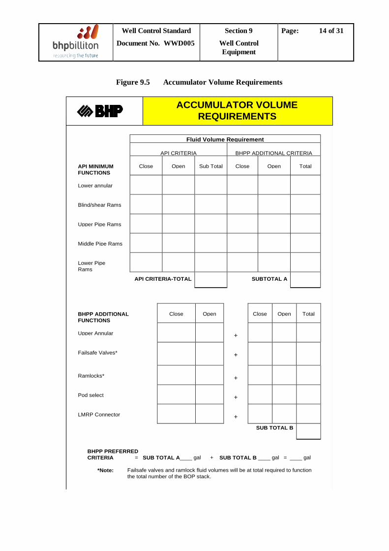
Well Control Standard
Document No. WWD005
Section 9
Well Control Equipment
Page: 14 of 31
Figure 9.5 Accumulator Volume Requirements
Fluid Volume Requirement
API CRITERIA BHPP ADDITIONAL CRITERIA
API MINIMUMFUNCTIONS
Close Open Sub Total Close Open Total
Lower annular
Blind/shear Rams
Upper Pipe Rams
Middle Pipe Rams
Lower PipeRams
API CRITERIA-TOTAL SUBTOTAL A
BHPP ADDITIONALFUNCTIONS
Close Open Close Open Total
Upper Annular +
Failsafe Valves* +
Ramlocks* +
Pod select +
LMRP Connector +
SUB TOTAL B
BHPP PREFERREDCRITERIA = SUB TOTAL A____ gal + SUB TOTAL B ____ gal = ____ gal
*Note: Failsafe valves and ramlock fluid volumes will be at total required to functionthe total number of the BOP stack.
ACCUMULATOR VOLUMEREQUIREMENTS
Well Control Standard
Document No. WWD005
Section 9
Well Control Equipment
Page: 15 of 31
9.4 BOP System Testing The safe and effective planning, preparation and execution of BOP system testing activities is intended to achieve the following: • Validate the correct function and initiation of the system.
• Validate that the BOP operating sequences are as intended.
• Confirm that the power, batteries, and communications systems are able to complete the sequence.
• Confirm that sufficient hydraulic volume and pressure will be available to complete the sequence.
BOP system testing must only commence after all maintenance is complete and prior to the BOP stack being run.
9.4.1 General Testing Practices
• The pressure and function testing requirements for the BOP system must comply with the relevant regulations of the governing regulatory agency for the area where the well is being drilled.
• BHPB Drilling’s requirement is that the BOP system should be pressure tested every
fourteen days. Where operations do not permit the BOP stack to be tested on schedule, approval to delay the test must be obtained from the Drilling Superintendent.
• The BOP pressure test sequence for a particular BOP stack should be based on the
following principles:
− All BOP system components should be subjected to test pressures in the direction that simulates the components use in service.
− The annular preventers should be pressure tested first in order to allow them additional time to relax prior to pulling the test plug.
− Ensure valves are open downstream of the component being pressure tested. − Maximise the number of components being tested on each test in order to minimise the
number of tests. − Ensure the downstream side of all upper choke and kill valves are pressure tested.
• Ensure rams and annular preventers are closed only on the correct size of drillpipe or test
mandrel. • All BOP system components shall be tested to a low pressure test of 200 psi prior to the
required final high pressure test value. • BOP system pressure tests should be conducted with the following criteria for a satisfactory
test:
− five minutes with no decline, or − fifteen minutes with a decline less than 5% of test pressure.
Well Control Standard
Document No. WWD005
Section 9
Well Control Equipment
Page: 16 of 31
• Test fluid volumes pumped and bled back must be carefully monitored and recorded. This
is particularly important when testing against the casing pack-off to avoid pressuring the casing annulus and risking casing collapse.
• The pod and control panel used should be alternated on each function and pressure test. • For MUX control systems with redundant SEMs, the Drilling Superintendent should
review and approve the proposed schedule for BOP testing to ensure that pods, stations and SEM’s are appropriately tested.
• All pressure tests shall be witnessed and signed for by the BHPB Drilling Supervisor.
Pressure tests shall be recorded on a chart recorder, reported in the IADC report and detailed in the BHPB BOP Pressure Test Report Form (Figure 9.6).
• Ensure all remote panels are used, in rotation, for carrying out routine BOP tests.
9.4.2 Deadman – Surface Test The Cameron Deadman System is an electrical Deadman circuit that resides in both pods on the LMRP and is powered by batteries. This system can be armed and disarmed from the BOP control panels. When loss of electrical (both sides) and hydraulic power (both sides) is detected, then both pods (and both SEMs within each pod) begin the pre-selected shut in sequence, activating the control system solenoids using the onboard battery power which will pilot pod valves supplied by the subsea accumulated hydraulic fluid.
Preparation Activities:
1.
2.
Have a clear and detailed plan to test every configuration
3.
BOP must be aligned to normal drilling mode
4.
PODS must be aligned to normal drilling mode
Ensure NO
5.
Pipe across BOP
6.
Hotline & Conduit hydraulic supply charged
7.
Stack accumulators charged
8.
Deadman armed and confirmed at panel.
Confirm that Deadman batteries are within usable criteria (periodic replacement and usage check as per Manufacturer recommendation) after the test and up to the end of the planned well. Replace as required prior to the test.
Execu1.
tion Activities: Isolate, one by one, the hydraulic supply and electrical power to PODs and SEMs according to predefined schedule.
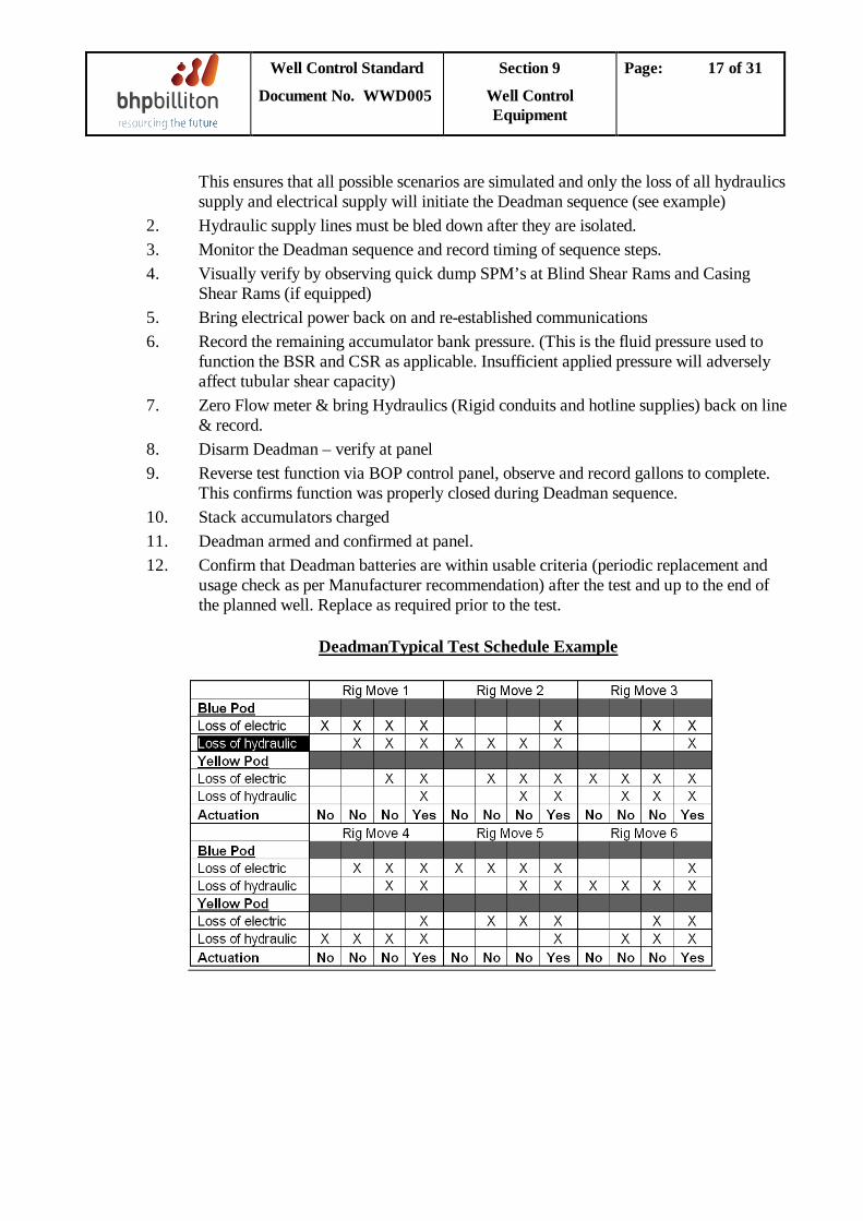
Well Control Standard
Document No. WWD005
Section 9
Well Control Equipment
Page: 17 of 31
2.
This ensures that all possible scenarios are simulated and only the loss of all hydraulics supply and electrical supply will initiate the Deadman sequence (see example)
3. Hydraulic supply lines must be bled down after they are isolated.
4. Monitor the Deadman sequence and record timing of sequence steps.
5.
Visually verify by observing quick dump SPM’s at Blind Shear Rams and Casing Shear Rams (if equipped)
6. Bring electrical power back on and re-established communications
7.
Record the remaining accumulator bank pressure. (This is the fluid pressure used to function the BSR and CSR as applicable. Insufficient applied pressure will adversely affect tubular shear capacity)
8.
Zero Flow meter & bring Hydraulics (Rigid conduits and hotline supplies) back on line & record.
9. Disarm Deadman – verify at panel
10.
Reverse test function via BOP control panel, observe and record gallons to complete. This confirms function was properly closed during Deadman sequence.
11. Stack accumulators charged
12. Deadman armed and confirmed at panel. Confirm that Deadman batteries are within usable criteria (periodic replacement and usage check as per Manufacturer recommendation) after the test and up to the end of the planned well. Replace as required prior to the test.
DeadmanTypical Test Schedule Example
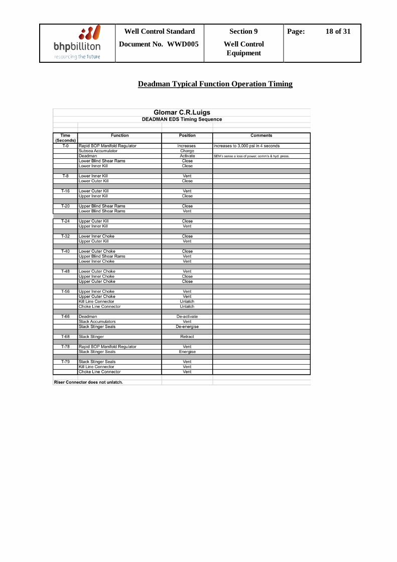
Well Control Standard
Document No. WWD005
Section 9
Well Control Equipment
Page: 18 of 31
Deadman Typical Function Operation Timing
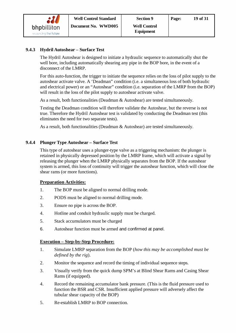
Well Control Standard
Document No. WWD005
Section 9
Well Control Equipment
Page: 19 of 31
9.4.3 Hydril Autoshear – Surface Test The Hydril Autoshear is designed to initiate a hydraulic sequence to automatically shut the well bore, including automatically shearing any pipe in the BOP bore, in the event of a disconnect of the LMRP.
For this auto-function, the trigger to initiate the sequence relies on the loss of pilot supply to the autoshear activate valve. A ‘Deadman” condition (i.e. a simultaneous loss of both hydraulic and electrical power) or an “Autoshear” condition (i.e. separation of the LMRP from the BOP) will result in the loss of the pilot supply to autoshear activate valve.
As a result, both functionalities (Deadman & Autoshear) are tested simultaneously.
Testing the Deadman condition will therefore validate the Autoshear, but the reverse is not true. Therefore the Hydril Autoshear test is validated by conducting the Deadman test (this eliminates the need for two separate tests).
As a result, both functionalities (Deadman & Autoshear) are tested simultaneously.
9.4.4 Plunger Type Autoshear – Surface Test This type of autoshear uses a plunger-type valve as a triggering mechanism: the plunger is retained in physically depressed position by the LMRP frame, which will activate a signal by releasing the plunger when the LMRP physically separates from the BOP. If the autoshear system is armed, this loss of continuity will trigger the autoshear function, which will close the shear rams (or more functions).
1. Preparation Activities:
2.
The BOP must be aligned to normal drilling mode.
3.
PODS must be aligned to normal drilling mode.
4.
Ensure no pipe is across the BOP.
5.
Hotline and conduit hydraulic supply must be charged.
6.
Stack accumulators must be charged
Autoshear function must be armed and confirmed at panel.
1.
Execution – Step-by-Step Procedure:
2.
Simulate LMRP separation from the BOP (how this may be accomplished must be defined by the rig).
3.
Monitor the sequence and record the timing of individual sequence steps.
4.
Visually verify from the quick dump SPM’s at Blind Shear Rams and Casing Shear Rams (if equipped).
5.
Record the remaining accumulator bank pressure. (This is the fluid pressure used to function the BSR and CSR. Insufficient applied pressure will adversely affect the tubular shear capacity of the BOP)
Re-establish LMRP to BOP connection.
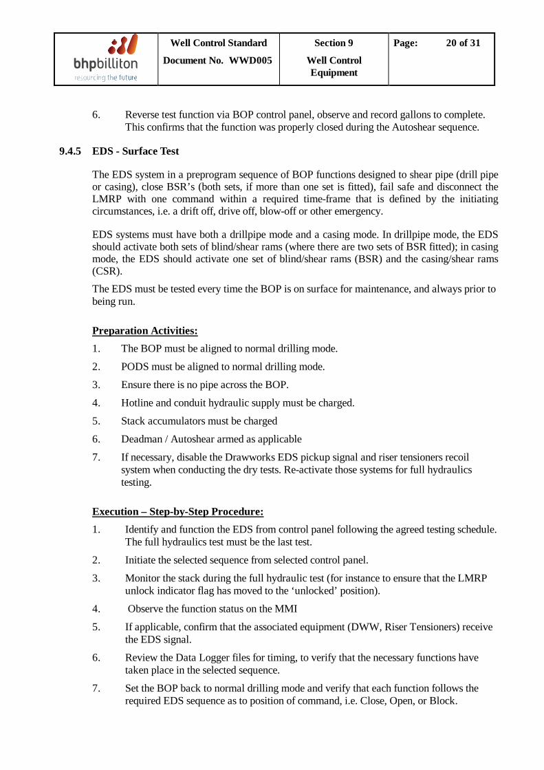
Well Control Standard
Document No. WWD005
Section 9
Well Control Equipment
Page: 20 of 31
6.
9.4.5 EDS - Surface Test
Reverse test function via BOP control panel, observe and record gallons to complete. This confirms that the function was properly closed during the Autoshear sequence.
The EDS system in a preprogram sequence of BOP functions designed to shear pipe (drill pipe or casing), close BSR’s (both sets, if more than one set is fitted), fail safe and disconnect the LMRP with one command within a required time-frame that is defined by the initiating circumstances, i.e. a drift off, drive off, blow-off or other emergency.
EDS systems must have both a drillpipe mode and a casing mode. In drillpipe mode, the EDS should activate both sets of blind/shear rams (where there are two sets of BSR fitted); in casing mode, the EDS should activate one set of blind/shear rams (BSR) and the casing/shear rams (CSR). The EDS must be tested every time the BOP is on surface for maintenance, and always prior to being run.
1. Preparation Activities:
2.
The BOP must be aligned to normal drilling mode.
3.
PODS must be aligned to normal drilling mode.
4.
Ensure there is no pipe across the BOP.
5.
Hotline and conduit hydraulic supply must be charged.
6.
Stack accumulators must be charged
7.
Deadman / Autoshear armed as applicable
If necessary, disable the Drawworks EDS pickup signal and riser tensioners recoil system when conducting the dry tests. Re-activate those systems for full hydraulics testing.
1. Execution – Step-by-Step Procedure:
2.
Identify and function the EDS from control panel following the agreed testing schedule. The full hydraulics test must be the last test.
3.
Initiate the selected sequence from selected control panel.
4.
Monitor the stack during the full hydraulic test (for instance to ensure that the LMRP unlock indicator flag has moved to the ‘unlocked’ position).
5.
Observe the function status on the MMI
6.
If applicable, confirm that the associated equipment (DWW, Riser Tensioners) receive the EDS signal.
7.
Review the Data Logger files for timing, to verify that the necessary functions have taken place in the selected sequence.
Set the BOP back to normal drilling mode and verify that each function follows the required EDS sequence as to position of command, i.e. Close, Open, or Block.
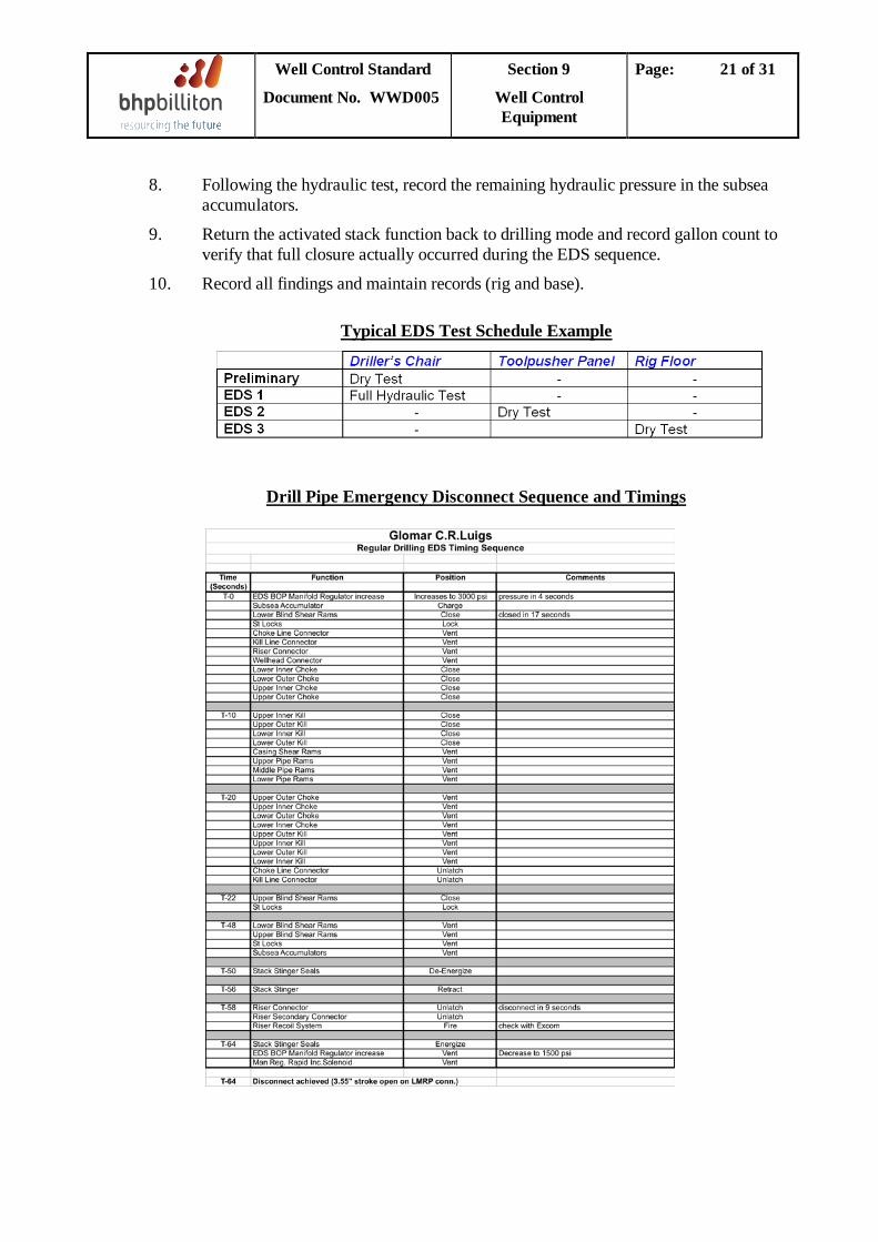
Well Control Standard
Document No. WWD005
Section 9
Well Control Equipment
Page: 21 of 31
8.
9.
Following the hydraulic test, record the remaining hydraulic pressure in the subsea accumulators.
10.
Return the activated stack function back to drilling mode and record gallon count to verify that full closure actually occurred during the EDS sequence.
Record all findings and maintain records (rig and base).
Typical EDS Test Schedule Example
Drill Pipe Emergency Disconnect Sequence and Timings
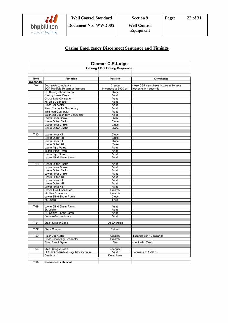
Well Control Standard
Document No. WWD005
Section 9
Well Control Equipment
Page: 22 of 31
Casing Emergency Disconnect Sequence and Timings
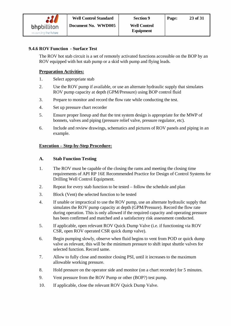
Well Control Standard
Document No. WWD005
Section 9
Well Control Equipment
Page: 23 of 31
9.4.6 ROV Function - Surface Test The ROV hot stab circuit is a set of remotely activated functions accessible on the BOP by an ROV equipped with hot stab pump or a skid with pump and flying leads.
1. Preparation Activities:
2.
Select appropriate stab
3.
Use the ROV pump if available, or use an alternate hydraulic supply that simulates ROV pump capacity at depth (GPM/Pressure) using BOP control fluid
4.
Prepare to monitor and record the flow rate while conducting the test.
5.
Set up pressure chart recorder
6.
Ensure proper lineup and that the test system design is appropriate for the MWP of bonnets, valves and piping (pressure relief valve, pressure regulator, etc).
Include and review drawings, schematics and pictures of ROV panels and piping in an example.
Execution – Step-by-Step Procedure:
A.
1. The ROV must be capable of the closing the rams and meeting the closing time requirements of API RP 16E Recommended Practice for Design of Control Systems for Drilling Well Control Equipment.
Stab Function Testing
2. Repeat for every stab function to be tested – follow the schedule and plan
3. Block (Vent) the selected function to be tested
4. If unable or impractical to use the ROV pump, use an alternate hydraulic supply that simulates the ROV pump capacity at depth (GPM/Pressure). Record the flow rate during operation. This is only allowed if the required capacity and operating pressure has been confirmed and matched and a satisfactory risk assessment conducted.
5. If applicable, open relevant ROV Quick Dump Valve (i.e. if functioning via ROV CSR, open ROV operated CSR quick dump valve).
6. Begin pumping slowly, observe when fluid begins to vent from POD or quick dump valve as relevant, this will be the minimum pressure to shift input shuttle valves for selected function. Record same.
7. Allow to fully close and monitor closing PSI, until it increases to the maximum allowable working pressure.
8. Hold pressure on the operator side and monitor (on a chart recorder) for 5 minutes.
9. Vent pressure from the ROV Pump or other (BOP?) test pump.
10. If applicable, close the relevant ROV Quick Dump Valve.
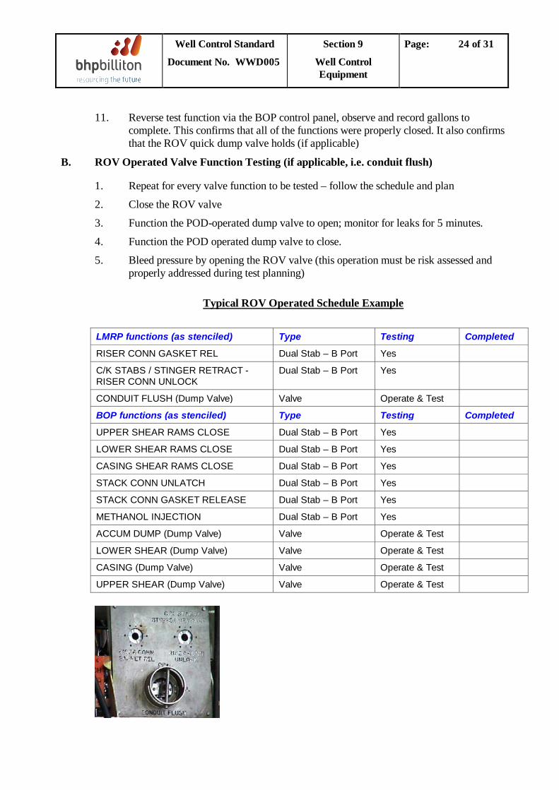
Well Control Standard
Document No. WWD005
Section 9
Well Control Equipment
Page: 24 of 31
11. Reverse test function via the BOP control panel, observe and record gallons to complete. This confirms that all of the functions were properly closed. It also confirms that the ROV quick dump valve holds (if applicable)
B. ROV Operated Valve Function Testing (if applicable, i.e. conduit flush)
1. Repeat for every valve function to be tested – follow the schedule and plan
2. Close the ROV valve
3. Function the POD-operated dump valve to open; monitor for leaks for 5 minutes.
4. Function the POD operated dump valve to close.
5. Bleed pressure by opening the ROV valve (this operation must be risk assessed and properly addressed during test planning)
Typical ROV Operated Schedule Example
LMRP functions (as stenciled) Type Testing Completed
RISER CONN GASKET REL Dual Stab – B Port Yes
C/K STABS / STINGER RETRACT - RISER CONN UNLOCK
Dual Stab – B Port Yes
CONDUIT FLUSH (Dump Valve) Valve Operate & Test
BOP functions (as stenciled) Type Testing Completed
UPPER SHEAR RAMS CLOSE Dual Stab – B Port Yes
LOWER SHEAR RAMS CLOSE Dual Stab – B Port Yes
CASING SHEAR RAMS CLOSE Dual Stab – B Port Yes
STACK CONN UNLATCH Dual Stab – B Port Yes
STACK CONN GASKET RELEASE Dual Stab – B Port Yes
METHANOL INJECTION Dual Stab – B Port Yes
ACCUM DUMP (Dump Valve) Valve Operate & Test
LOWER SHEAR (Dump Valve) Valve Operate & Test
CASING (Dump Valve) Valve Operate & Test
UPPER SHEAR (Dump Valve) Valve Operate & Test
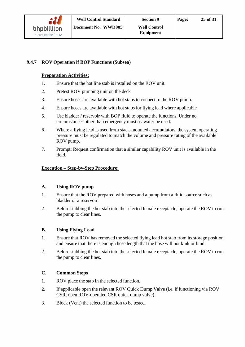
Well Control Standard
Document No. WWD005
Section 9
Well Control Equipment
Page: 25 of 31
9.4.7 ROV Operation if BOP Functions (Subsea)
1. Ensure that the hot line stab is installed on the ROV unit. Preparation Activities:
2. Pretest ROV pumping unit on the deck
3. Ensure hoses are available with hot stabs to connect to the ROV pump.
4. Ensure hoses are available with hot stabs for flying lead where applicable
5. Use bladder / reservoir with BOP fluid to operate the functions. Under no circumstances other than emergency must seawater be used.
6. Where a flying lead is used from stack-mounted accumulators, the system operating pressure must be regulated to match the volume and pressure rating of the available ROV pump.
7. Prompt: Request confirmation that a similar capability ROV unit is available in the field.
Execution – Step-by-Step Procedure:
A. 1.
Using ROV pump
2.
Ensure that the ROV prepared with hoses and a pump from a fluid source such as bladder or a reservoir.
B.
Before stabbing the hot stab into the selected female receptacle, operate the ROV to run the pump to clear lines.
1. Using Flying Lead
2.
Ensure that ROV has removed the selected flying lead hot stab from its storage position and ensure that there is enough hose length that the hose will not kink or bind.
Before stabbing the hot stab into the selected female receptacle, operate the ROV to run the pump to clear lines.
1. C. Common Steps
2.
ROV place the stab in the selected function.
3.
If applicable open the relevant ROV Quick Dump Valve (i.e. if functioning via ROV CSR, open ROV-operated CSR quick dump valve).
Block (Vent) the selected function to be tested.
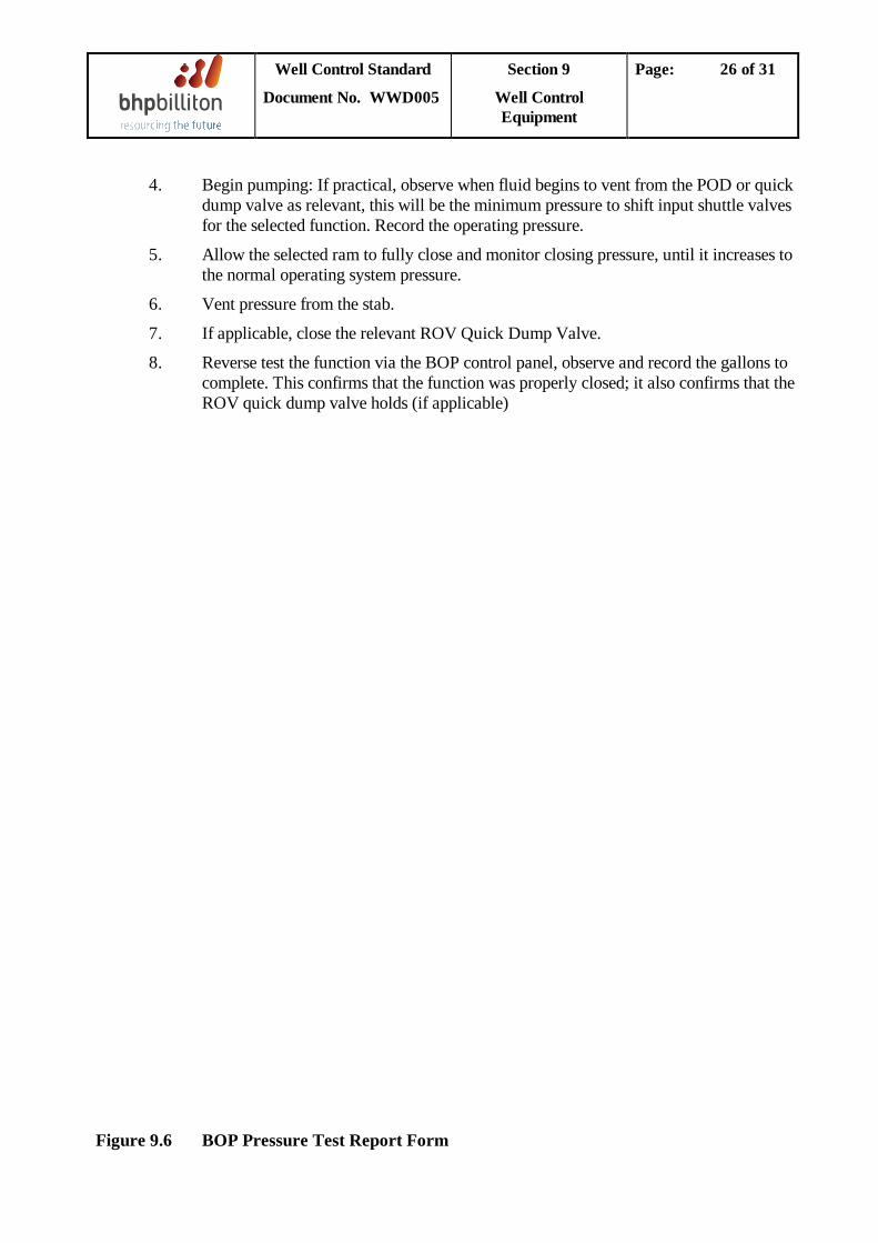
Well Control Standard
Document No. WWD005
Section 9
Well Control Equipment
Page: 26 of 31
4.
5.
Begin pumping: If practical, observe when fluid begins to vent from the POD or quick dump valve as relevant, this will be the minimum pressure to shift input shuttle valves for the selected function. Record the operating pressure.
6.
Allow the selected ram to fully close and monitor closing pressure, until it increases to the normal operating system pressure.
7.
Vent pressure from the stab.
8.
If applicable, close the relevant ROV Quick Dump Valve.
Reverse test the function via the BOP control panel, observe and record the gallons to complete. This confirms that the function was properly closed; it also confirms that the ROV quick dump valve holds (if applicable)
Figure 9.6 BOP Pressure Test Report Form
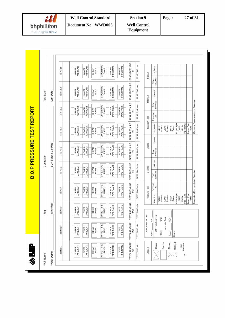
Well Control Standard
Document No. WWD005
Section 9
Well Control Equipment
Page: 27 of 31
Test
No.
1Te
st N
o.2
Test
No.
3Te
st N
o.4
Test
No.
5Te
st N
o.6
Test
No.
7Te
st N
o.8
Test
No.
9Te
st N
o.10
TEST
PR
ESSU
RE
PSI
TEST
PR
ESSU
RE
PSI
TEST
PR
ESSU
RE
PSI
TEST
PR
ESSU
RE
PSI
TEST
PR
ESSU
RE
PSI
TEST
PR
ESSU
RE
PSI
TEST
PR
ESSU
RE
PSI
TEST
PR
ESSU
RE
PSI
TEST
PR
ESSU
RE
PSI
TEST
PR
ESSU
RE
PSI
TEST
TIM
E m
in.
TEST
TIM
E m
in.
TEST
TIM
E m
in.
TEST
TIM
E m
in.
TEST
TIM
E m
in.
TEST
TIM
E m
in.
TEST
TIM
E m
in.
TEST
TIM
E m
in.
TEST
TIM
E m
in.
TEST
TIM
E m
in.
Lege
nd Clo
sed
Ope
ned
Clo
sed
Ope
ned
Inpu
tPr
essu
re
BOP
Pres
sure
Tes
t
Pane
l :__
____
PO
D:_
____
_
BOP
Func
tion
Test
Pane
l :__
____
PO
D:_
____
_
Acou
stic
Tes
t
Pane
l :__
____
PO
D:_
____
_
Not
es:
Pres
sure
Tse
tO
pene
dC
lose
dFu
nctio
n Te
stO
pene
dC
lose
d Volu
me
Tim
eSe
cond
sVo
lum
eTi
me
Seco
nds
Pres
sure
psi
Func
tion
Volu
me
Tim
eSe
cond
sFu
nctio
nPr
essu
reps
iTi
me
Seco
nds
Volu
me
Upp
erAn
nula
rLo
wer
Annu
lar
Shea
rR
ams
Upp
er P
ipe
Ram
sM
iddl
ePi
pe R
ams
Low
er P
ipe
Ram
s
Upp
erAn
nula
rLo
wer
Annu
lar
Shea
rR
ams
Upp
er P
ipe
Ram
sM
iddl
ePi
pe R
ams
Low
er P
ipe
Ram
sC
ontra
ctor
s R
epre
sent
ativ
e Si
gnat
ure
Com
pany
Rep
rese
ntat
ive'
s Si
gnat
ure
UPP
ERAN
NU
LAR
LOW
ERAN
NU
LAR
SHEA
RR
AMS
UPP
ER P
IPE
RAM
S
MID
DLE
PIPE
RAM
S
LOW
ERPI
PE R
AMS
UPP
ERAN
NU
LAR
LOW
ERAN
NU
LAR
SHEA
RR
AMS
UPP
ER P
IPE
RAM
S
MID
DLE
PIPE
RAM
S
LOW
ERPI
PE R
AMS
UPP
ERAN
NU
LAR
LOW
ERAN
NU
LAR
SHEA
RR
AMS
UPP
ER P
IPE
RAM
S
MID
DLE
PIPE
RAM
S
LOW
ERPI
PE R
AMS
UPP
ERAN
NU
LAR
LOW
ERAN
NU
LAR
SHEA
RR
AMS
UPP
ER P
IPE
RAM
S
MID
DLE
PIPE
RAM
S
LOW
ERPI
PE R
AMS
UPP
ERAN
NU
LAR
LOW
ERAN
NU
LAR
SHEA
RR
AMS
UPP
ER P
IPE
RAM
S
MID
DLE
PIPE
RAM
S
LOW
ERPI
PE R
AMS
UPP
ERAN
NU
LAR
LOW
ERAN
NU
LAR
SHEA
RR
AMS
UPP
ER P
IPE
RAM
S
MID
DLE
PIPE
RAM
S
LOW
ERPI
PE R
AMS
UPP
ERAN
NU
LAR
LOW
ERAN
NU
LAR
SHEA
RR
AMS
UPP
ER P
IPE
RAM
S
MID
DLE
PIPE
RAM
S
LOW
ERPI
PE R
AMS
UPP
ERAN
NU
LAR
LOW
ERAN
NU
LAR
SHEA
RR
AMS
UPP
ER P
IPE
RAM
S
MID
DLE
PIPE
RAM
S
LOW
ERPI
PE R
AMS
UPP
ERAN
NU
LAR
LOW
ERAN
NU
LAR
SHEA
RR
AMS
UPP
ER P
IPE
RAM
S
MID
DLE
PIPE
RAM
S
LOW
ERPI
PE R
AMS
UPP
ERAN
NU
LAR
LOW
ERAN
NU
LAR
SHEA
RR
AMS
UPP
ER P
IPE
RAM
S
MID
DLE
PIPE
RAM
S
LOW
ERPI
PE R
AMS
Wat
er D
epth
:W
ellh
ead:
BOP
Stac
k Si
ze/T
ype
Last
Dat
e
Wel
l Nam
e:R
ig:
Con
tract
orTe
st D
ate
B.O
.P P
RES
SUR
E TE
ST R
EPO
RT
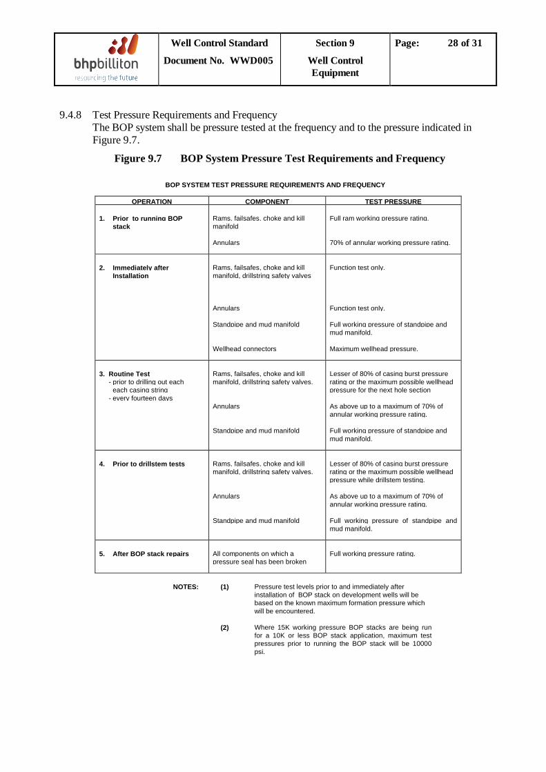
Well Control Standard
Document No. WWD005
Section 9
Well Control Equipment
Page: 28 of 31
9.4.8 Test Pressure Requirements and Frequency The BOP system shall be pressure tested at the frequency and to the pressure indicated in
Figure 9.7.
Figure 9.7 BOP System Pressure Test Requirements and Frequency
BOP SYSTEM TEST PRESSURE REQUIREMENTS AND FREQUENCY
OPERATION COMPONENT TEST PRESSURE
1. Prior to running BOP stack
Rams, failsafes, choke and killmanifold
Annulars
Full ram working pressure rating.
70% of annular working pressure rating.
2. Immediately after Installation
Rams, failsafes, choke and killmanifold, drillstring safety valves
Annulars
Standpipe and mud manifold
Wellhead connectors
Function test only.
Function test only.
Full working pressure of standpipe andmud manifold.
Maximum wellhead pressure.
3. Routine Test - prior to drilling out each
each casing string - every fourteen days
Rams, failsafes, choke and killmanifold, drillstring safety valves.
Annulars
Standpipe and mud manifold
Lesser of 80% of casing burst pressurerating or the maximum possible wellheadpressure for the next hole section
As above up to a maximum of 70% ofannular working pressure rating.
Full working pressure of standpipe andmud manifold.
4. Prior to drillstem tests Rams, failsafes, choke and killmanifold, drillstring safety valves.
Annulars
Standpipe and mud manifold
Lesser of 80% of casing burst pressurerating or the maximum possible wellheadpressure while drillstem testing.
As above up to a maximum of 70% ofannular working pressure rating.
Full working pressure of standpipe andmud manifold.
5. After BOP stack repairs All components on which apressure seal has been broken
Full working pressure rating.
NOTES: (1) Pressure test levels prior to and immediately after installation of BOP stack on development wells will be based on the known maximum formation pressure which will be encountered.
(2) Where 15K working pressure BOP stacks are being runfor a 10K or less BOP stack application, maximum testpressures prior to running the BOP stack will be 10000psi.
Well Control Standard
Document No. WWD005
Section 9
Well Control Equipment
Page: 29 of 31
9.4.9 Stack Testing Procedure
Prior to running the BOP stack, a function and pressure testing procedure on the stump must be performed. The objectives of these tests are to ensure proper function and pressure integrity of all components.
Stump Test
a. All accumulator bottles on the BOP and LMRP must be checked for precharge pressure. Required pressures vary with water depth and bottle function. The precharge pressure of the surface accumulator bottles shall also be checked prior to the BOP stack being run (see Section 9.4.4).
b. The acoustic beacons should be fully charged and all electrical components tested. c. Visually inspect lines, hoses, valves, bottles etc. on the exterior of the stack for indications
of leaks or damage. d. Pressure test ram preventers, fail-safe valves and wellhead connector to full working
pressure rating of the equipment. Pressure test annular preventers and LMRP connector to half of the full working pressure rating of the annulars.
e. Function test all BOP stack functions, open and close modes, with 1500 psi regulator
pressure using both pods. Also function test the acoustic system on the appropriate functions. Record opening and closing volumes and times. Compare volumes with nominal values.
f. Install new steel wellhead connector gasket.
All Tests After Stack Landed
a. The choke and kill manifold shall be pressure tested prior to performing the stack test and shall be done concurrently with other operations.
b. Function test both annulars and all rams and fail-safes. c. Pull nominal seat protector if wellhead type requires it. d. Run test plug and test wellhead connector. e. Retrieve test plug and rerun nominal seat protector as required. f. Re-align valves on the choke and kill manifold to the drilling configuration.
Well Control Standard
Document No. WWD005
Section 9
Well Control Equipment
Page: 30 of 31
9.4.10 Diverter System Testing
A function and pressure test of the diverter system should be conducted prior to spudding the well. The recommended procedure is as follows:
1. A test plate designed to be picked up on drillpipe and seal on the bottom of the diverter housing should be fabricated if the rig does not have one. The plate must have a drillpipe box connection to allow it to be picked up and also must have circulating ports to allow full circulation through the drillpipe.
2. Install diverter element. Pick up plate from trolley in moonpool with drillpipe and kelly and
pull up to seal on bottom of diverter housing. Close diverter element. Pump seawater at maximum pump rate out both overboard lines.
3. Temporarily connect air control lines to allow the shaker line and both diverter valves to be
closed. Pressure test diverter system to 50-100 psi with water. Reconnect air control lines to original configuration and function test. Pump through lines to confirm they are connected correctly.
4. Open diverter element. Rig down test plate.
9.4.11 Accumulator Drill a. Pre-Charge Pressure Test
This test should be conducted on each well prior to spudding and every 30 days thereafter at convenient times. i. Shut off all accumulator pumps. ii. Drain the accumulators to the reservoir. iii. Using a charging and gauging assembly, check the nitrogen pre-charge on each bottle. iv. Recharge or bleed bottles as required (see table below).
Accumulator
Rating (psi)
Nominal Pre-Charge
(psi)
Minimum Pre-Charge
(psi)
Maximum Pre-Charge
(psi) 1500 750 750 850 2000 1000 950 1100 3000 1000 950 1100
Well Control Standard
Document No. WWD005
Section 9
Well Control Equipment
Page: 31 of 31
b. Closing Test
This test should be carried out before BOP stack tests.
i. Position a drill pipe stand in the BOP stack. ii. Isolate the power supply to the accumulator pumps. iii. Record the accumulator pressure. Set the annular preventer pressure to 1500 psi. iv. Close and open all the well control functions as appropriate. (Apart from blind/shear
rams.) v. Simulate the closing of the blind/shear rams. After each step, record the volume used,
the time taken and the residual pressure. Ensure that the final accumulator pressure is at least 200 psi greater than the pre-charge pressure.
vi. Inspect the reservoir and confirm that the fluid is free from any debris or contaminants. vii. Prepare and switch on the accumulator pumps. Record the time to charge the
accumulator to the normal operating pressure.
c. Closing Unit Pump Test
This test should be conducted before any BOP stack test. It can be scheduled either immediately before or after the accumulator closing test. Prior to starting this test, ensure that the hydraulic reservoir is free from any debris or contaminants.
i. Position a drill pipe stand in the BOP stack. ii. Isolate the accumulators from the closing unit manifold. iii. If the closing unit pumps are air driven, isolate the normal rig air supply to the pumps
and operate them from dedicated air accumulation. If the pumps are dual powered (i.e. air and electric), both power supplies should be separately tested.
iv. Close the annular preventer and open choke line fail-safe valves. Record the time for the pumps to close the annular, open the choke line valves and produce 200 psi over the pre-charge pressure. If it takes longer than 2 minutes it is an indication that the system is performing unsatisfactorily. The following areas should be checked:-
• Systems Pre-charge (all bottles correctly pre-charged) • Control System (all valves operating smoothly, no leaks) • Ram Operation (all rams operating smoothly) • Accumulator Charge Pressure (normally set at 3000 psi)
v. Close the choke line valves, open the annular preventer and recommission the
accumulator and closing unit.
Well Control Standard
Document No. WWD005
Section 10
Well Control for Deepwater Drilling
Page: 1 of 11
TABLE OF CONTENTS
10.1 Introduction .................................................................................................................................2
10.2 Fracture Gradients ......................................................................................................................2
10.3 Choke Line Pressure Loss ..........................................................................................................2
10.4 Choke Line Fluid Displacement ................................................................................................8
10.5 Subsea Accumulator Volume ......................................................................................................9
10.6 Gas in Riser ............................................................................................................................... 10
10.7 Stack Gas Cleanout .................................................................................................................. 10
Well Control Standard
Document No. WWD005
Section 10
Well Control for Deepwater Drilling
Page: 2 of 11
10.1 Introduction
Well control for deepwater drilling differs from those operations in shallower water for the following reasons:
• Lower formation fracture gradients • Higher choke line pressure losses • Greater fluid displacement effects in choke line. • Greater expansion of a gas bubble in the riser.
10.2 Fracture Gradients
Fracture gradients at any particular depth decrease as the water depth increases. This results from a larger section of the overburden being comprised of water instead of rock.
10.3 Choke Line Pressure Loss
The frictional pressure loss is directly proportional to the length of the choke line. Deep-water drilling operations therefore have significant choke line pressure losses (PCL
During circulating out a kick, the circulating rate selected should be such that the resulting choke line pressure loss is less than the SICP. If not, the formation will be exposed to a higher pressure than required to kill the well (see next page for examples).
). The choke line pressure loss will result in additional pressure being applied, which may lead to formation fracturing in the open hole.
Choke line pressure loss can be determined using standard hydraulics calculations based on the choke line ID and the mud properties. Although it is preferable to measure the actual pressure loss it may not be operationally practical due to alternate fluid (glycol-water) in the choke line.
The pressure loss shall be predetermined by one of the following three methods:
1. Prior to drilling out the casing, take slow circulating rate (SCR) pressures by first circulating up the riser, shutting in at the BOP stack and then circulating up the choke line. The difference between these two pressures is the choke line pressure loss (PCL
Obtain kill line pressure loss (KLP) using the same technique.
).
2. After drilling ahead, it is recommended to measure the choke line pressure loss using a method that does not expose the open formation to additional pressures. In order to determine the most suitable SCR, pump down the choke line with the rig pumps and record pressure versus rate for the range of SCR's. Use a pressure gauge as close as possible to the choke line. Obtain KLP using the same technique.
Choke line pressure loss should change as the mud weight changes. It is recommended that the choke line pressure loss be re-measured for significant changes in mud weights, i.e. 0.2 SG.
3. For situations where the choke line pressure loss has not been measured, an estimate can be obtained as follows:
Well Control Standard
Document No. WWD005
Section 10
Well Control for Deepwater Drilling
Page: 3 of 11
PCL = (6.41)(MW)0.8 (Q)1.8 (PV)0.2
(D) where:
P
4.80
CLMW = mud weight (ppg)
= choke line pressure loss (psi/100 ft)
Q = flow rate (bbl/min.) PV = plastic viscosity (cp) D = internal diameter (in)
The effect of the choke line pressure loss can be compensated for by use of one of the following procedures:
10.3.1 Casing Pressure Adjustment To maintain constant bottomhole pressure while circulating, the sum of the annular pressure components must be kept constant. These components include the mud hydrostatic pressure, casing pressure and frictional pressure losses primarily through the choke line. When the well is static, the annulus pressure reduces to mud hydrostatic pressure and casing pressure only. As the pump is brought up to the required SCR, the choke pressure should be allowed to fall below the initial SICP by an amount equal to the estimated choke line pressure loss.
10.3.2 Kill Line Monitor (Preferred Method) The kill line provides a method of measuring the pressure being maintained on the annulus which is exclusive of kill line frictional pressure losses, by opening the kill line fail-safe valves and lining out the choke manifold to monitor the static kill line pressure.
As the pump rate is brought up to the slow circulating rate, maintain the kill line pressure constant by adjusting the choke. The choke pressure will decrease from the original SICP by an amount equal to the choke line pressure loss.
As the pump rate is brought up to the SCR, two situations may arise:
Case 1: Indicated choke pressure at the desired SCR is greater than the choke line friction pressure (see schematic below).
Case 2: Indicated choke pressure at the desired SCR is less than the choke line friction pressure (see schematic below).
In Case 1 the choke line friction pressure will be fully compensated for (by choke position changes) until such time during the displacement that the required choke pressure is less than the sum of choke line friction pressure and the wide open choke pressure. (In most cases this will occur only when the original mud behind the influx is passing the choke, at which time subsurface pressures are unlikely to be critically high). Thus, if ‘Case 1’ is applicable, the choke line frictional pressure loss will not impose a limit on circulation rate.
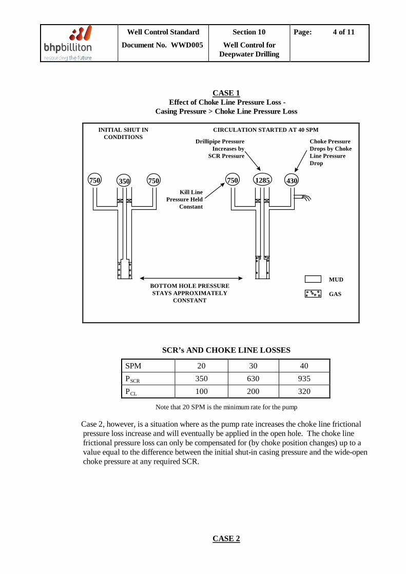
Well Control Standard
Document No. WWD005
Section 10
Well Control for Deepwater Drilling
Page: 4 of 11
Effect of Choke Line Pressure Loss - CASE 1
Casing Pressure > Choke Line Pressure Loss
SCR’s AND CHOKE LINE LOSSES
SPM 20 30 40 P 350 SCR 630 935 P 100 CL 200 320
Note that 20 SPM is the minimum rate for the pump
Case 2, however, is a situation where as the pump rate increases the choke line frictional pressure loss increase and will eventually be applied in the open hole. The choke line frictional pressure loss can only be compensated for (by choke position changes) up to a value equal to the difference between the initial shut-in casing pressure and the wide-open choke pressure at any required SCR.
750 350 750 750 1285 430Kill Line
Pressure HeldConstant
Drillipipe PressureIncreases by
SCR Pressure
Choke PressureDrops by ChokeLine PressureDrop
MUD
GASBOTTOM HOLE PRESSURESTAYS APPROXIMATELY
CONSTANT
INITIAL SHUT INCONDITIONS
CIRCULATION STARTED AT 40 SPM
CASE 2
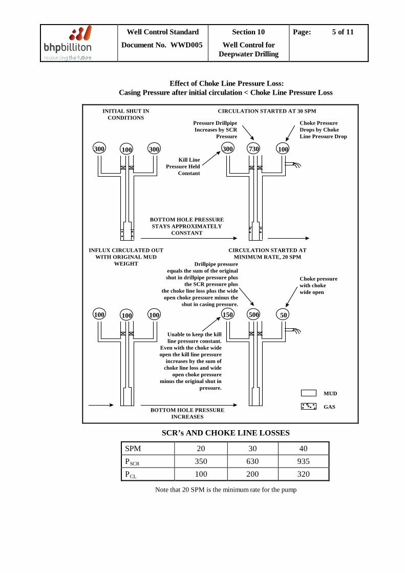
Well Control Standard
Document No. WWD005
Section 10
Well Control for Deepwater Drilling
Page: 5 of 11
Effect of Choke Line Pressure Loss: Casing Pressure after initial circulation < Choke Line Pressure Loss
SCR’s AND CHOKE LINE LOSSES
SPM 20 30 40 P 350 SCR 630 935 P 100 CL 200 320
Note that 20 SPM is the minimum rate for the pump
MUD
GAS
100 100 100 150 500 50
Unable to keep the killline pressure constant.
Even with the choke wideopen the kill line pressure
increases by the sum ofchoke line loss and wide
open choke pressureminus the original shut in
pressure.
Drillpipe pressureequals the sum of the originalshut in drillpipe pressure plus
the SCR pressure plusthe choke line loss plus the wideopen choke pressure minus the
shut in casing pressure.
Choke pressurewith chokewide open
BOTTOM HOLE PRESSUREINCREASES
INFLUX CIRCULATED OUTWITH ORIGINAL MUD
WEIGHT
CIRCULATION STARTED ATMINIMUM RATE, 20 SPM
300 100 300 300 730 100Kill Line
Pressure HeldConstant
Pressure DrillpipeIncreases by SCR
Pressure
Choke PressureDrops by ChokeLine Pressure Drop
BOTTOM HOLE PRESSURESTAYS APPROXIMATELY
CONSTANT
INITIAL SHUT INCONDITIONS
CIRCULATION STARTED AT 30 SPM
Well Control Standard
Document No. WWD005
Section 10
Well Control for Deepwater Drilling
Page: 6 of 11
a) Estimate Additional Wellbore Pressure Due to Choke Line Friction The additional pressures exerted in the well bore due to choke line losses at pump start up may be determined as follows: Case 1: There will be no additional pressure in the well bore due to choke line
frictional pressure at pump start-up. Case 2: There will be additional wellbore pressure exerted due to choke line frictional
pressure at pump start-up - = PCL - Pa + P
OC
where: PCL P
= choke line frictional pressure loss at SCR (psi). a
P= initial annulus shut-in pressure (psi).
OC
= choke pressure at SCR recorded with the choke wide open (psi).
Since all of these pressures, and annulus friction pressure, will have an effect throughout the circulating system, they must be analysed at all points in the system and in particular at the open hole weakest point (usually the casing shoe).
b) Estimate the Initial Circulating Pressure
The initial circulating pressure (i.e. standpipe pressure) once the pump is up to SCR is estimated as follows: Case 1: PIC = Pdp + P
SCR
Case 2: PIC = Pdp + PSCR + PCL + POC - P
a
where: PICP
= initial circulating pressure (psi) dp
P= shut in drillpipe pressure that reflects the kick zone pressure (psi).
SCR P
= slow circulating rate pressure (psi). CL
P= choke line frictional pressure loss at SCR (psi).
a P
= initial annulus shut-in pressure (psi). OC
= choke pressure at SCR, recorded with the choke wide open (psi).
c) Estimate the Final Circulating Pressure The final circulating pressure (i.e. standpipe pressure), once kill weight mud reaches the bit, is estimated as follows: Case 1: PFC = PSCR x MW1
MW2
Case 2: PFC = (PSCR x MW2) + PCL + POC - P MW1
a
where: PFC MW2 = weight of kill mud (ppg)
= final circulating pressure (i.e. standpipe pressure) (psi)
Well Control Standard
Document No. WWD005
Section 10
Well Control for Deepwater Drilling
Page: 7 of 11
MW1 = weight of original mud (ppg)
d) Monitor Kill Line Pressure For Case 1, the pressure indicated on the kill line pressure gauge should be held constant
as the pump is brought up to speed (SCR), by progressively opening the choke and whereupon the choke pressure will decrease. Once the pump is up to speed, the choke pressure observed will have reduced by an amount equal to the choke line pressure loss.
For Case 2, the pressure indicated on the kill line pressure gauge should initially be held constant as the pump is started up. However, at some point before the pump is up to speed (i.e at some pump rate less than the SCR) the observed kill line pressure will start to increase because the choke size limit will be reached. Once the pump is up to speed the choke will be wide open and the pressure recorded on the kill line gauge will have increased by that portion of the choke line frictional pressure loss which cannot be compensated for by a further increase in choke size. The pressure increase seen on the kill line gauge, monitoring the wellbore pressure at the bottom of the choke line, will be equal to PCL + POC - Pa
.
e) Check Circulating Pressure at SCR Once the pump reaches SCR, if the circulating pressure is significantly different from the calculated value, the pump should be stopped, the well shut in and the reason for the discrepancy determined. If the circulating pressure is equal to, or reasonably close to, the calculated value, the kill displacement should continue. Any small difference seen will most likely be due to the fact that the actual SCR pressure is different from the value used to calculate the initial circulating pressure. The actual SCR pressure can be established from the initial circulating pressure recorded when the pump is up to speed. For Case 1, the actual SCR pressure can be determined from the initial circulating pressure as follows: PSCR = Pic - P
dp
For Case 2, the actual SCR pressure can be determined as follows: PSCR = PIC - Pdp - PCL - POC + P
a
f) Recalculate Final Circulating Pressure
For the ‘Wait and Weight’ method, the final circulating pressure (i.e. standpipe pressure), once kill weight mud reaches the bit, must be recalculated as follows: Case 1: PFC = PSCR x MW1
MW2
Well Control Standard
Document No. WWD005
Section 10
Well Control for Deepwater Drilling
Page: 8 of 11
Case 2: PFC = (PSCR x MW2) + PCL + POC - P MW1
a
where: MW2 = weight of kill mud (ppg) MW1 = weight of original mud (ppg) The standpipe pressures used on the well kill worksheet should be amended to reflect the recalculated final circulating pressure.
g) Assess Effects of Choke Line Pressure Loss after Influx Circulated Out
Case 1: In the later stages of displacement the choke pressure required to maintain constant bottom hole pressure will drop. This drop will be most noticeable once the influx has been circulated through the choke, i.e. when the original mud behind the influx reaches the choke.
If the required choke pressure drops below the sum of the choke line pressure loss and the wide open choke pressure loss at the chosen SCR, it will no longer be possible to completely compensate for the choke line pressure loss by further opening the choke so as to lower well bore pressure. The resultant increase in wellbore pressure at this stage will be equal to:
PCL + POC - P
a
In practice, the choke will be wide open at this stage and the standpipe pressure will rise above the estimated final circulating pressure. When the hole has been circulated to kill weight mud, the standpipe pressure will have increased by the sum of the choke line pressure loss and the wide open choke pressure loss.
Case 2: As the influx expands, the choke pressure required at surface will increase. As the required choke pressure increases it will be possible to compensate for an increasing proportion of the choke line pressure losses. If the required choke pressure increases to a value equal to the sum of the choke line loss and the wide open choke pressure loss, it will be possible to compensate for the total amount of choke line pressure loss.
It should be noted that the most critical period in terms of downhole pressure is likely to occur at the early stage of displacement, while the influx is across the BHA and occupies a maximum height in the annulus, the condition in which the weak point in the well is usually exposed to the highest wellbore pressure. In this respect, the change in choke line pressure loss at the later stage in the kill displacement that is referred to above, is not likely to be a major consideration.
10.4 Choke Line Fluid Displacement
Well Control Standard
Document No. WWD005
Section 10
Well Control for Deepwater Drilling
Page: 9 of 11
During mud-gas displacement in the choke line while circulating out a kick, there will be changes in the hydrostatic pressure of the fluid column, the bottomhole pressure and, after a time lag, the drillpipe pressure. The change in hydrostatic pressure can occur rapidly and is extremely difficult to compensate for by choke manipulation. As gas enters the choke line a low-density fluid is displacing a much higher density fluid, with the result that the hydrostatic pressure decreases. Unless an adjustment is made to the casing pressure being maintained, the bottomhole pressure will decrease. Similarly, as mud enters the choke line following the gas influx, the hydrostatic pressure and hence the bottomhole pressure will increase unless an adjustment is made at the choke. The following techniques are recommended to attempt to minimise the effect of choke line fluid displacement on bottomhole pressures: 1. Kill Line Monitor
In cases where only one choke line is used to flow-up the influx, the static kill line can be used to monitor the annulus pressure. The kill line pressure will provide an early warning that the pressure at the BOP stack is changing and that so is the bottomhole pressure. Choke adjustments can be made earlier to attempt to maintain the drillpipe pressure constant.
2. Flow Through Both Lines
It may be advantageous on deep-water wells to consider flowing through both the choke and kill lines to minimise both the frictional pressure loss and the effect of choke line fluid displacement. For a given pump rate, flowing through both lines should result in one quarter of the frictional pressure loss and a halving of the rate of pressure change due to fluid displacement effects, as compared to flowing through one line. The disadvantage of this technique is that a backup redundant line is no longer available in the event of line blockage or washout.
3. Reduce Circulating Rate
A reduction in circulating rate shall provide additional reaction time for the choke operator. This should be done by stopping the pump, shutting-in the well and restarting at a slower rate. To restart circulation, maintain casing pressure constant at the SICP observed during the shutdown. Slowly bring the pump up to the new circulating rate and then maintain constant drillpipe pressure at the observed standpipe pressure reading. To be effective, it must be done prior to the gas reaching the BOP stack, as at this point casing pressures may be fluctuating rapidly, making it difficult to recommence circulation while maintaining constant bottom hole pressure.
10.5 Subsea Accumulator Volume The BOP control system utilised on deepwater drilling rigs is generally either an electro-hydraulic or a multiplex system to greatly reduce response times when operating stack functions. The usable volume of fluid contained in the subsea accumulators is critical.
Well Control Standard
Document No. WWD005
Section 10
Well Control for Deepwater Drilling
Page: 10 of 11
Typically it takes between 30 and 60 seconds for the surface accumulators to recharge the subsea accumulators after closing a single ram when water depths are in excess of 450 m. Virtually all deepwater rigs and the majority of the floaters have a subsea acoustic back-up system for emergency use that relies entirely on the fixed fluid volume. It is important that the usable volume be accurately known. The calculation of usable subsea volume particularly in deepwater, is complicated by the fact that the nitrogen used for pre-charge purposes does not behave as an ideal gas, that is PV/T is no longer constant. Obviously, if there is a substantial difference in surface (pre-charging) versus subsea temperature, even in shallower water depths, significant error may be introduced using ideal gas relationships. Generally, in water depths to 300 m. this error approaches 15%, which is adequately covered by the "pre-charge plus 200 psi" pressure remaining criteria outlined in API RP53 and increasing to 75% in 3050 m WD. A far more accurate calculation procedure utilising nitrogen specific volume must be used in water depths greater than 300 m and should be used to check usable volume for emergency acoustic systems in all cases. Accumulator volume calculations are covered in Section 9.3.
10.6 Gas in Riser In deeper water, the consequences of expansion of a gas bubble in the riser is potentially more significant because of the greater pressure differential between atmosphere and the wellhead. Once in the riser gas cannot be contained, it can only be diverted. In extreme cases it could lead to the unloading of the riser and possible riser collapse. Standing orders for the driller shall include the following. 1. Flow check at trip tank (ensure that the trip tank pump is on and running).
2. If flowing, close diverter in “Riser Degas” sequence:
3. Continue to observe flow until flow stops or diverting is required (Closely Monitor flow back and pressure in the MGS) NOTE: maximum pressure = 50 psi. MGS holds 60 bbls; 80% of the calculated liquid leg value is not to be exceeded whilst circulating fluids from the riser.
4. When flow stops, isolate one pit. Circulate at +/- 1,000gpm in “Riser Degas” mode until suspected gas level is at +/- 3,000ft below the rotary table.
Closely monitor PVT, flow and MGS Pressure.
5. When there is a PVT increase, flow increase, increase in MGS pressure, or the riser is observed flowing, immediately shut down pump if pumping.
6. Shut pump off and flow check with gas at 3,000ft BRT and thereafter flow check every 1,000ft until gas reaches surface. Circulate at +/- 400gpm from 3,000ft to surface or until gas starts to breakout.
7. Divert directly overboard if MGS is approaching liquid seal pressure or if there is a concern that the slip joint packer may fail.
10.7 Stack Gas Cleanout
Well Control Standard
Document No. WWD005
Section 10
Well Control for Deepwater Drilling
Page: 11 of 11
Similarly, in deeper water, the consequences of expansion of a gas bubble in the riser from gas trapped in the BOP’s after killing a well is potentially more significant, because of the greater pressure differential between atmosphere and the wellhead. If, after killing the well, the BOP below the annular preventer contains gas and the annular is opened before the gas is cleaned out, it could also lead to the unloading of the riser and possible riser collapse. Standing orders for the driller shall include the following: [Initial condition: Well has been killed on the Upper Flex Rams and there is no gas below the Annular BOP, or the Annular Preventer is already open] 1. Close the lowermost VBR’s and Kill line directly below the Hang-off Rams. 2. Open Choke line above Lower VBR and Kill line directly below Hang-off Rams. 3. Displace base oil (or water if WBM used) down Choke line and up Kill line. 4. Bleed pressure to atmospheric through Choke and Kill line, monitoring for flow using the
Stripping tank. 5. Displace riser to kill weight mud if not previously done. 6. Open the Lower Choke and Upper Kill Valves, then open the Flex rams to allow mud to U-
tube up the Choke and Kill lines while keeping the riser full. 7. Close Upper Flex rams, open Upper Kill line and displace the lighter fluid down the Lower
Choke line and Upper Kill line with kill weight mud. 8. Open Variable Bore Rams (VBR’s) and monitor the well on the Trip tank. 9. Continue with normal operations. [Initial condition: Annular BOP and flex rams closed] 1. Close all failsafe valves below the Hang-off rams. 2. Open choke line above Flex Rams and sweep line below annular. 3. Displace down choke line through the Upper Choke Valves and up Kill Lines through the
Sweep Valves to base oil (or to water if using WBM). 4. With Flex Rams closed, bleed pressure to atmospheric through the Choke and Kill line.
Monitor the flow through the Stripping tank. 5. Displace riser to kill weight mud if not previously done. 6. Open Annular Preventer to allow mud to U-tube up Choke and Kill lines while top-filling
the riser with the trip tank or the quick fill line (if the trip tank is used, ensure that the trip tank (pump?) is running prior to opening the Annular Preventer.
7. Close Annular Preventer. 8. Pump kill weight mud down the Choke line and up the Kill line through the Sweep Valves
with returns to the Mud Gas Separator (MGS). 9. If the flex rams were used in the well kill operation, clear the gas from below the Flex
Rams as detailed above. If the well was killed on the Annular only, open the Annular and Flew Rams and observe the well on the trip tank (ensure that the trip tank pump is running prior to opening the well)
10. Continue with normal operations.

Well Control Standard
Document No. WWD005
Section 11
Highly Deviated/ Horizontal Wells
Page: 1 of 5
TABLE OF CONTENTS
11.1 Introduction .................................................................................................................................2
11.2 Highly Deviated Wells .................................................................................................................2
11.3 Horizontal Wells ..........................................................................................................................4
Well Control Standard
Document No. WWD005
Section 11
Highly Deviated/ Horizontal Wells
Page: 2 of 5
11.1 Introduction
Although the kill calculations are identical for straight, deviated and horizontal wells (true vertical depths used in all cases) and the well control procedures are based on the same principles, certain considerations should be implemented by the DSV and drilling engineer during both the planning and operational phases of the deviated drilling campaign. This section contains guidelines to assist these personnel.
11.2 Highly Deviated Wells
Although calculations for kill mud weight and initial circulating pressure are identical to those in vertical wells, the construction of the kill graph for a deviated well is more complicated.
In order to construct the graph it is first necessary to divide the well bore into manageable sections as shown in Figure 11.1, based on inclination, i.e.:
• surface to end of vertical section • build-up section • tangent section to bit
The slope of the kill graph is assumed to be constant for each section, hence if the well trajectory is complicated, more sections may be necessary to reduce inaccuracy.
The graph is constructed by calculating the standpipe pressure at the start of the kill by the normal calculation (i.e. PIC = PSCR
+ SIDPP, see Section 8.2), and then for when the kill mud reaches the beginning and end of each section using the following formula:
PFSPP = PISPP + X (PSCRF - PSCRI Y
) - (1.421)(H)(KMW - OMW)
OR
PFSPP = PISPP + X (PSCRF - PSCRI Y
) - (0.052)(H)(KMW - OMW)
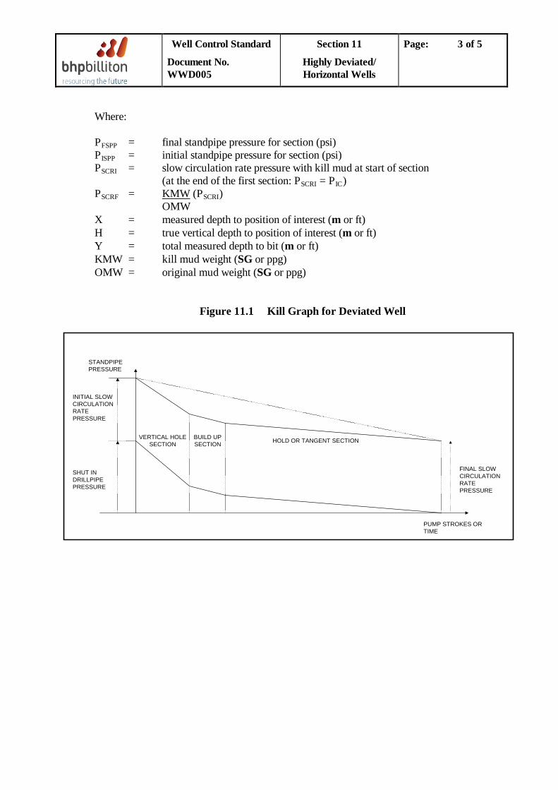
Well Control Standard
Document No. WWD005
Section 11
Highly Deviated/ Horizontal Wells
Page: 3 of 5
Where: PFSPPP
= final standpipe pressure for section (psi) ISPP
P = initial standpipe pressure for section (psi)
SCRI (at the end of the first section: P
= slow circulation rate pressure with kill mud at start of section SCRI = PIC
P)
SCRF = KMW (PSCRI OMW
)
X = measured depth to position of interest (m or ft) H = true vertical depth to position of interest (m or ft) Y = total measured depth to bit (m or ft) KMW = kill mud weight (SG or ppg) OMW = original mud weight (SG or ppg)
Figure 11.1 Kill Graph for Deviated Well
HOLD OR TANGENT SECTIONBUILD UPSECTION
VERTICAL HOLESECTION
SHUT INDRILLPIPEPRESSURE
INITIAL SLOWCIRCULATIONRATEPRESSURE
STANDPIPEPRESSURE
FINAL SLOWCIRCULATIONRATEPRESSURE
PUMP STROKES ORTIME
Well Control Standard
Document No. WWD005
Section 11
Highly Deviated/ Horizontal Wells
Page: 4 of 5
11.3 Horizontal Wells
Horizontal wells are not likely to be drilled as wild cat or even exploration wells except under extreme surface location conditions. It is normal practice for horizontal wells to be drilled in a discovered reservoir where knowledge of the pore and fracture pressure profiles is clear. Consequently, understanding of primary well control is better due to the reliability of well data. The most likely kicks are swabbed ones due to the high drag factors along the horizontal section. Some aspects of influx behaviour and the subsequent effects on surface monitoring equipment are known from observation.
The following are practical considerations especially applicable to well control in horizontal wells, and in deviated wells to a lesser degree:
1. Tripping
In general, the bottom hole assemblies used to drill horizontal wells are not as likely to cause swabbing as those run in vertical wells. However, substantial reservoir intervals may be exposed, increasing the potential for swabbing and making induced kicks greater than in a vertical well. For this reason the mud shall be in good condition prior to pulling out, and the string should be pumped out through tight spots.
Extreme caution shall be exercised when returning to bottom following a trip. The horizontal section of the wellbore could be partially or completely filled with swabbed hydrocarbons despite the well being static (i.e. not flowing). Bottoms up should be circulated through the choke for the last 750m (2500 ft) as a precaution.
2. Influx Volume and Nature
In the event of a kick in a horizontal well it is virtually impossible to determine the nature of the influx (i.e. oil, gas, water) due to equivalent shut in drill pipe and casing pressures. It may be difficult to validate data obtained during a kick and hence it is recommended to assume a gas influx at all times.
3. Influx Migration
Very high influx migration rates of up to 600 m/hr (2000 ft/hr) in high angle wells have been recorded, due to the way the influx moves along the high-side of the hole.
4. Productivity
The economic rationale responsible for the implementation of a horizontal Drilling Programme should be kept in mind when considering well control issues. The enhanced productivity and amount of reservoir section exposed tend to increase the rate of influx. Rig personnel should be particularly cognisant of well control procedures while drilling through the pay zone, especially if drilling at the balance point with non-damaging brines. Well control should never be ignored due to directional control problems.
Well Control Standard
Document No. WWD005
Section 11
Highly Deviated/ Horizontal Wells
Page: 5 of 5
5. Formation Pressure
The formation pressure profile can be simplified as a straight line relationship with negative slope to the depth at which the well reaches 89 degrees, then the relationship of pressure versus depth changes to a straight line of zero slope.
6. Drill Pipe Schedule
The drill pipe schedule graph for a circulating kill should be drawn as a straight line pressure reduction (as for a normally inclined or vertical well), for the vertical part of the well only and as a horizontal line thereafter, since the kill mud weight will have no impact on the bottomhole pressure thereafter (see Section 11.1 for calculation method).
7. Choke Operation
Depending on the hole configuration and the horizontal length, it is important to realise that while the drill pipe is dead when the kill mud reaches the horizontal section, the influx may also still be contained in the horizontal section. In such a case the choke operator will be expecting to maintain a final circulation pressure constant on the drill pipe by minimal adjustment of the choke, when the true impact of the kick in the non-horizontal part of the well will be much delayed. Consequently a sudden increase in the annulus pressure should be expected when a significant portion of the influx reaches the non-horizontal and occupies a greater height in the annulus.
Well Control Standard
Document No. WWD005
Section 12
Other Well Control Topics
Page: 1 of 9
TABLE OF CONTENTS
12.1 Well Control for Oil Base Mud or Synthetic Mud ................................................................. 2
12.2 Gas Hydrates ........................................................................................................................... 3
12.3 Stack Gas Clearing Procedure ................................................................................................... 5
12.4 Circulating Kill Problems .......................................................................................................... 5
12.5 Loss of Secondary Well Control ................................................................................................ 7
12.5.1 Cement Plug ....................................................................................................................... 7
12.5.2 Barite Plug .......................................................................................................................... 7
12.6 Well Control Simulators ............................................................................................................. 8
12.7 Formation Sampling in Deep Water ......................................................................................... 9
Well Control Standard
Document No. WWD005
Section 12
Other Well Control Topics
Page: 2 of 9
12.1 Well Control for Oil Base Mud or Synthetic Mud
Special well control procedures are required when drilling with oil base mud (OBM) as gas, which may not dissolve in a water base mud, may dissolve in the base oil component of an OBM system. The gas remains in solution until the pressure is reduced to the bubble point for the mixture. The dissolved gas then rapidly comes out of solution causing a large increase in volume. This volume increase displaces mud from the well causing a reduction in hydrostatic pressure, which can result in a kick being taken. This problem is particularly serious in floating drilling if the bubble point pressure is reached when the gas laden mud is above the BOPs in the riser, because the evolution and expansion of gas will be uncontrolled and there will be no opportunity to close in or contain the gas.
There is no appreciable difference between oil base and water base mud systems in the influx volume recorded at surface for any given gas kick size. The net volume of gas plus mud is only approximately 2-3% less than the total of the separate gas and mud volumes for an OBM. The ability to detect an influx when it occurs is therefore similar for both water base and oil base mud systems.
If the initial pit gain is not detected, however, significant differences exist between OBM and WBM in the ability to detect the influx as it is circulated to surface. For water base mud, the gas bubbles continually increase in volume as the pressure is reduced. For oil base mud, very little expansion occurs until the pressure is reduced to the bubble point. The bubble point pressure, which is usually reached when the influx is within a few hundred metres of surface, is dependent upon the composition of the drilling fluid and gas influx.
OBM also has higher thermal expansion characteristics than water base muds. The mud expands at bottomhole temperature reducing the density of the fluid and causing a reduction in hydrostatic pressure. For some well geometries, this can give rise to flow from the well, during logging for instance, due to expansion of the mud.
The following procedures should he followed whenever drilling with OBM:
1. The mud company should supply to the Drilling Engineer at the well planning stage the gas solution characteristics of the particular oil mud system, to identify if any special precautions are required. In the absence of such solubility data, assume the solubility characteristics of mineral base oil.
2. Drilling Contractor and service company personnel should be instructed as to the
characteristics of a gas kick with OBM. The Toolpusher, Driller, drill crew and Mud Engineer must be fully aware of the procedures to be followed when OBM is in use.
3. Flow checks should be conducted for all kick warning signs for a minimum duration of
fifteen minutes.
Well Control Standard
Document No. WWD005
Section 12
Other Well Control Topics
Page: 3 of 9
4. Circulate bottoms up suspected well flow indicators. Close the annular and circulate through the choke line when bottoms up is 600 m from surface. The choke should be fully open and the pump rate reduced to the slow circulating rate when circulating through the choke line.
5. On floaters, ensure the diverter element is installed at all times to allow flow to be
diverted if gas breaks out of solution above the BOP stack and unloads the riser.
12.2 Gas Hydrates
Gas hydrates can present serious problems during well control operations. Gas hydrates are complex crystalline structures of hydrocarbons and water having the appearance of hard snow. They can form at temperatures above the normal freezing point of water under certain pressure conditions. This formation process is accelerated where there are high gas velocities, pressure pulsations or other agitations which cause mixing of the hydrate components.
The conditions for hydrate formation can be predicted using Figure 12.1. These pressure and temperature conditions can exist in a well control operation where low geothermal gradients exist, in deepwater operations where low seafloor water temperatures exist, or downstream of a pressure drop in the system, i.e. choke. This can result in plugging of subsea choke and kill lines or plugging of surface lines downstream of the choke.
Prevention of gas hydrates can be accomplished by maintaining pressures and temperatures outside the hydrate range, or by suppressing the hydrate formation temperature by injecting glycol into the gas stream. In well control operations pressure or temperature control methods for gas hydrate prevention are usually not possible, therefore use of glycol injection is recommended.
A gas hydrate contingency plan should be formulated for all wells where the potential exists for gas hydrate formation. This should be based on water depth, seafloor temperatures and potential well pressures. The contingency plan should provide a method of injecting glycol at the BOP stack.
A suggested method of accomplishing this is to pump glycol down the kill line with the cement unit and slowly inject it into the well as the gas approaches surface and enters the choke line. For more information on gas hydrates formation, see GCD017, Well Testing Standard, Section 4.8.
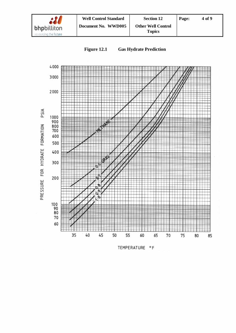
Well Control Standard
Document No. WWD005
Section 12
Other Well Control Topics
Page: 4 of 9
Figure 12.1 Gas Hydrate Prediction
Well Control Standard
Document No. WWD005
Section 12
Other Well Control Topics
Page: 5 of 9
12.3 Stack Gas Clearing Procedure
After the well is killed a gas bubble may be trapped between the preventer and the choke line outlet that was used for circulation. This gas bubble can result in a large volume of gas being liberated at surface conditions, particularly if the preventer used was an annular, the BOP stack is in deepwater, or high mud weights are in use. Stack gas must be removed before the BOP is opened since expansion of this gas may cause a second kick to be introduced in the well, cause a flash fire, or injure personnel on the drill floor.
The exact procedure to be used for clearing stack gas is dependent on the BOP stack configuration and the preventer and choke line used for the well control operation. The general principles involved, however, are as follows:
1. Isolate the well from the BOP stack by closing the lower pipe rams. 2. Keep the upper annular closed. 3. Displace kill and choke lines to gelled water via the choke manifold. As the gelled
water is displaced up the choke line, be prepared for gas expansion. Hold only minimum backpressure to prevent heavy surging.
4. Displace choke line volume the second time holding zero backpressure. 5. With both chokes in full open position, open annular and allow weighted mud to u-
tube up the choke line. Keep the riser full with kill weight mud while the choke line is being u-tubed.
6. After the choke line has stopped flowing, close the annular and displace both kill and
choke lines to kill weight mud by circulating down the kill line and back up the choke line.
7. Open all preventers and check for flow. Circulate a minimum of 120% riser contents
watching for gas expansion.
12.4 Circulating Kill Problems
Conventional well killing procedures are based upon the assumption that all of the well control equipment operates as designed and the wellbore is able to withstand the imposed pressures. Mechanical problems and formation fracturing, however, occurs occasionally during well killing operations causing complications with conventional procedures.
Careful consideration must be given to a the available well data before selecting an alternative procedure. Figure 12.2 outlines the possible problem cause for several unexpected changes in surface measurements.
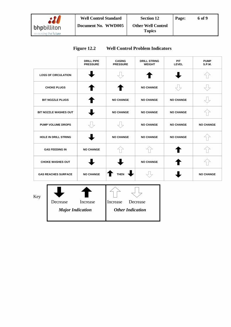
Well Control Standard
Document No. WWD005
Section 12
Other Well Control Topics
Page: 6 of 9
Figure 12.2 Well Control Problem Indicators
NO CHANGE
NO CHANGE
GAS REACHES SURFACE
CHOKE WASHES OUT
GAS FEEDING IN
HOLE IN DRILL STRING
PUMP VOLUME DROPS
BIT NOZZLE WASHES OUT
BIT NOZZLE PLUGS
CHOKE PLUGS
LOSS OF CIRCULATION
THEN
NO CHANGE
NO CHANGE
NO CHANGE
NO CHANGE
NO CHANGE
NO CHANGE
NO CHANGE
NO CHANGE
NO CHANGE
NO CHANGE
NO CHANGE
NO CHANGE
NO CHANGE
NO CHANGE
NO CHANGE
DRILL PIPEPRESSURE
CASINGPRESSURE
DRILL STRINGWEIGHT
PITLEVEL
PUMPS.P.M.
Key Decrease Increase Increase Decrease
Major Indication Other Indication
Well Control Standard
Document No. WWD005
Section 12
Other Well Control Topics
Page: 7 of 9
12.5 Loss of Secondary Well Control
When equipment failure, hole deterioration underground blowout, etc., threaten the loss of secondary well control, complete isolation of the kicking zone is required. This can sometimes be achieved by:
• Cement plug • Barite plug
These methods are termed Tertiary Well Control Techniques and often result in stuck pipe.
12.5.1 Cement Plug
The use of cement offers little chance of recovering the drillstring since cement is often displaced up the annulus, particularly around stabilisers in the BHA. It must also be considered that there is a poor chance of achieving adequate cement isolation in the annulus between the BHA and hole. In addition, cementing will often result in the drill string becoming plugged preventing further cementing attempts without resorting to perforating the drill pipe. Consequently cement plugs should be considered a last resort.
If attempted, the cement slurry design should take account of the following factors:
• Spacer type and volume must prevent contamination during displacement. • Surface lines must be free of potential contaminants. • Gas channelling must be minimised by application of appropriate cement recipe
technology. • Slurry volume must be sufficient to allow for displacement into the formation. • Slurry density must be sufficient to provide overbalance during displacement
12.5.2 Barite Plug
This is a mixture of barite and water or diesel. The objective is to utilise the rapid settling effect of the barite in water, in the absence of any viscosifier, to rapidly form an impermeable barrier to flow.
The following is a guide to the typical recipes for 1 barrel of barite plug . The mud engineer should perform pilot testing prior to pumping:
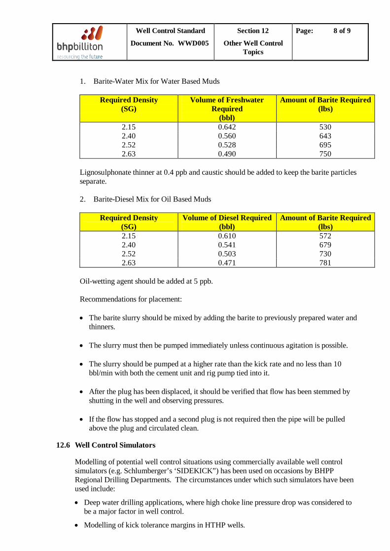
Well Control Standard
Document No. WWD005
Section 12
Other Well Control Topics
Page: 8 of 9
1. Barite-Water Mix for Water Based Muds
Required Density (SG)
Volume of Freshwater Required
(bbl)
Amount of Barite Required (lbs)
2.15 0.642 530 2.40 0.560 643 2.52 0.528 695 2.63 0.490 750
Lignosulphonate thinner at 0.4 ppb and caustic should be added to keep the barite particles separate. 2. Barite-Diesel Mix for Oil Based Muds
Required Density (SG)
Volume of Diesel Required (bbl)
Amount of Barite Required (lbs)
2.15 0.610 572 2.40 0.541 679 2.52 0.503 730 2.63 0.471 781
Oil-wetting agent should be added at 5 ppb. Recommendations for placement: • The barite slurry should be mixed by adding the barite to previously prepared water and
thinners. • The slurry must then be pumped immediately unless continuous agitation is possible. • The slurry should be pumped at a higher rate than the kick rate and no less than 10
bbl/min with both the cement unit and rig pump tied into it. • After the plug has been displaced, it should be verified that flow has been stemmed by
shutting in the well and observing pressures.
• If the flow has stopped and a second plug is not required then the pipe will be pulled above the plug and circulated clean.
12.6 Well Control Simulators
Modelling of potential well control situations using commercially available well control simulators (e.g. Schlumberger’s ‘SIDEKICK”) has been used on occasions by BHPP Regional Drilling Departments. The circumstances under which such simulators have been used include:
• Deep water drilling applications, where high choke line pressure drop was considered to be a major factor in well control.
• Modelling of kick tolerance margins in HTHP wells.
Well Control Standard
Document No. WWD005
Section 12
Other Well Control Topics
Page: 9 of 9
• Determination of maximum gas volume at surface and maximum expected surface gas flow-rate when circulating out a kick.
Subsequent evaluation of the results of such simulations and their comparison with conventional simplistic modelling has shown that such dynamic simulation generally provides little added value over the usual static approach. Conventional graphical solutions will suffice for most operations, for example for estimation of casing shoe pressure from influx volume and mud weights; gas surface volume; gas surface flowrate, etc.
Use of well control simulators should generally be avoided other than for unusually complex wells, for example HTHP wells in deep water with small diameter choke/kill lines.
12.7 Formation Sampling in Deep Water Where formation fluid sampling ahs been performed with MDT, RCI or similar wireline tools, caution must be exercise when circulating the well following any pump-out operations. The mud logging from ahead of the pumped-out reservoir fluid should be brought up the choke and / or kill lines with the BOP’s closed and until clean mud returns are observed at surface. Care should be taken to ensure that constant bottom-hole pressure is maintained throughout the circulation.
Well Control Standard Document No.
WWD005
Appendix 1 Example
Calculations
Page: 1 of 4
APPENDIX 1
WELL CONTROL EXAMPLE CALCULATION:
WELL KILL PROCEDURE
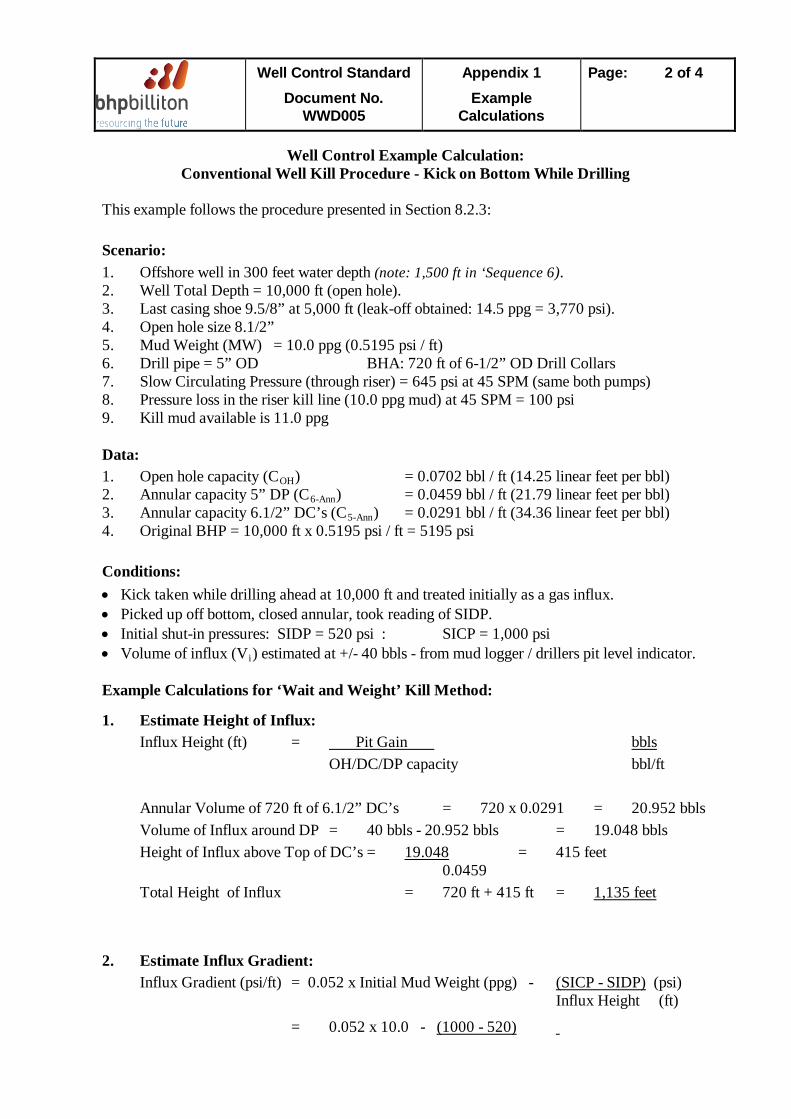
Well Control Standard Document No.
WWD005
Appendix 1 Example
Calculations
Page: 2 of 4
Well Control Example Calculation:
Conventional Well Kill Procedure - Kick on Bottom While Drilling This example follows the procedure presented in Section 8.2.3: Scenario: 1. Offshore well in 300 feet water depth (note: 1,500 ft in ‘Sequence 6). 2. Well Total Depth = 10,000 ft (open hole). 3. Last casing shoe 9.5/8” at 5,000 ft (leak-off obtained: 14.5 ppg = 3,770 psi). 4. Open hole size 8.1/2” 5. Mud Weight (MW) = 10.0 ppg (0.5195 psi / ft) 6. Drill pipe = 5” OD BHA: 720 ft of 6-1/2” OD Drill Collars 7. Slow Circulating Pressure (through riser) = 645 psi at 45 SPM (same both pumps) 8. Pressure loss in the riser kill line (10.0 ppg mud) at 45 SPM = 100 psi 9. Kill mud available is 11.0 ppg Data: 1. Open hole capacity (COH2. Annular capacity 5” DP (C
) = 0.0702 bbl / ft (14.25 linear feet per bbl) 6-Ann
3. Annular capacity 6.1/2” DC’s (C) = 0.0459 bbl / ft (21.79 linear feet per bbl)
5-Ann4. Original BHP = 10,000 ft x 0.5195 psi / ft = 5195 psi
) = 0.0291 bbl / ft (34.36 linear feet per bbl)
Conditions: • Kick taken while drilling ahead at 10,000 ft and treated initially as a gas influx. • Picked up off bottom, closed annular, took reading of SIDP. • Initial shut-in pressures: SIDP = 520 psi : SICP = 1,000 psi • Volume of influx (Vi
) estimated at +/- 40 bbls - from mud logger / drillers pit level indicator.
Example Calculations for ‘Wait and Weight’ Kill Method:
1. Estimate Height of Influx: Influx Height (ft) = Pit Gain
OH/DC/DP capacity bbl/ft bbls
Annular Volume of 720 ft of 6.1/2” DC’s = 720 x 0.0291 = 20.952 bbls Volume of Influx around DP = 40 bbls - 20.952 bbls = 19.048 bbls Height of Influx above Top of DC’s = 19.048 0.0459
= 415 feet
Total Height of Influx = 720 ft + 415 ft = 1,135 feet
2. Estimate Influx Gradient: Influx Gradient (psi/ft) = 0.052 x Initial Mud Weight (ppg) - (SICP - SIDP)
= 0.052 x 10.0 -
(psi) Influx Height (ft)
(1000 - 520)
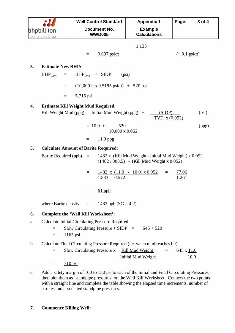
Well Control Standard Document No.
WWD005
Appendix 1 Example
Calculations
Page: 3 of 4
1,135
= 0.097 psi/ft
3. Estimate New BHP:
(~ 0.1 psi/ft)
BHPNew = BHPOrig
= (10,000 ft x 0.5195 psi/ft) + 520 psi
+ SIDP (psi)
= 5,715 psi
4. Estimate Kill Weight Mud Required:
Kill Weight Mud (ppg) = Initial Mud Weight (ppg) + (SIDP)
= 10.0 +
(psi) TVD x (0.052)
520 10,000 x 0.052
(ppg)
=
5. Calculate Amount of Barite Required:
11.0 ppg
Barite Required (ppb) = (1482 / 808.5) - (Kill Mud Weight x 0.052)
1482 x (Kill Mud Weight - Initial Mud Weight) x 0.052
= 1482 x (11.0 - 10.0) x 0.052 =
1.833 - 0.572 1.261 77.06
=
61 ppb
where Barite density = 1482 ppb (SG = 4.2)
6. Complete the ‘Well Kill Worksheet’: a. Calculate Initial Circulating Pressure Required
= Slow Circulating Pressure + SIDP = 645 + 520 =
b. Calculate Final Circulating Pressure Required (i.e. when mud reaches bit)
1165 psi
= Slow Circulating Pressure x Kill Mud Weight = 645 x 11.0 Initial Mud Weight 10.0
=
c. Add a safety margin of 100 to 150 psi to each of the Initial and Final Circulating Pressures, then plot them as ‘standpipe pressures’ on the Well Kill Worksheet. Connect the two points with a straight line and complete the table showing the elapsed time increments, number of strokes and associated standpipe pressures.
710 psi
7. Commence Killing Well:
Well Control Standard Document No.
WWD005
Appendix 1 Example
Calculations
Page: 4 of 4
Follow the well kill procedure detailed above. Keep the casing at the original shut-in value until the pump rate is brought up to speed (45 SPM), and then adjust the choke until the drillpipe pressure is at the calculated ‘Initial Circulating Pressure’. Note that the casing pressure should now reduce - by around the amount of ‘pressure loss’ previously measured in the choke line at 45 SPM (i.e. 100 psi).
Well Control Standard Document No. WWD005
Appendix 2 Well Control
Example Calc’s
Page: 1 of 5
APPENDIX 2
WELL CONTROL EXAMPLE CALCULATION:
COMBINED STRIPPING &
VOLUMETRIC KILL PROCEDURE
Well Control Standard Document No. WWD005
Appendix 2 Well Control
Example Calc’s
Page: 2 of 5
Well Control Example Calculation:
Combined Stripping and Volumetric Kill Procedure This example follows the procedure presented in Section 8.4.3: Scenario: 1. Well Total Depth = 5,500 ft (open hole). 2. Last casing shoe 9.5/8” at 3,500 ft (leak-off obtained: 14.5 ppg). 3. Open hole size 8.1/2” 4. Mud Weight (MW) = 11.5 ppg (0.598 psi/ft) 5. Drill pipe = 5” OD BHA: 6-1/2” OD Drill Collars - 8 stands = 720 ft Conditions: • Circulated bottoms-up prior to POOH for bit change - abnormal hole fill noticed. Flow check
showed hole stable. • During trip out, flow check 4,500 ft showed well flowing, stabbed Gray valve, closed in on the
annular preventer. • Initial shut-in pressure = 140 psi (= PAnn
• 20 bbls gain observed in trip tank. ).
• Now preparing to strip back in the hole to TD to perform well kill. Preparation: A. While preparing for stripping, allow the closed-in annulus pressure to build up to Pchoke and
where Pchoke = PAnn + Ps + Pw
P
(see ‘step 3’ below)
Pann
s
P
=
w
= =
initial closed-in annulus pressure before stripping commences. the ‘entering influx margin’ or allowance for loss of hydrostatic pressure as the gas is displaced from below the bit to around the drill collars when the bit is run into the influx.
the ‘overbalance margin’, i.e. the working pressure increment (50 - 200 psi), in this case say 100 psi.
B. Determine CAnn - DC to OH capacity: CAnn Determine C
= 0.0291 bbl / ft OH - open hole capacity: COH
= 0.0702 bbl / ft (14.25 linear ft / bbl)
C. Estimate the height of the influx:
Height of influx = 20 bbl x 14.25 ft / bbl = 285 ft D. Calculate gradient of influx (IG):
Original Conditions: BHP = 5500 x 0.598 = 3289 psi
New Conditions: 3289 psi = hydrostatic of mud column + hyd. of gas column + initial SIP (PAnn
= [(5500 - 285) x 0.598] + (285 x IG) + 140 )
Well Control Standard Document No. WWD005
Appendix 2 Well Control
Example Calc’s
Page: 3 of 5
Thus, IG = 0.105 psi / ft (note - confirms assumption that influx is gas)
Example Calculation: 1. Prepare the Stripping Worksheet (Figure 8.3): (a) Calculate the hydrostatic pressure per barrel of mud for 6-1/2” DC in 8.1/2” open hole (in
11.5 ppg mud = 0.598 [si/ft mud).
Equivalent hydrostatic pressure per barrel = MG Ann. Capacity bbl
psi
= 0.598 / 0.0291 =
20.55 psi / bbl
(b) Calculate the volume of mud displaced by the 5” drill pipe (usually referred to as the ‘closed end displacement volume’) for each foot of pipe stripped-in: Mud displaced = π (D)2 ft3
4 / ft
where: D = drill pipe diameter in feet (5” = 0.4167 ft) Mud displaced = π (0.4167)2 ft3 / ft = 0.1364 ft3
4 / ft
=
0.025 bbl / ft
2. Calculate Ps
(the ‘entering influx margin’):
Ps = (MG - IG) (Vi / CAnn - Vi / COH
) psi
Ps
= (0.598 - 0.105) (20 / 0.0291 - 20 / 0.0702) psi
= (0.493) (687.3 - 284.9) psi
= 198 psi (say, 200 psi
)
This loss of hydrostatic is explained by the greater height of the gas column when it is displaced from below the bit to the DC annulus as the bit is stripped-in:
Increased influx height: = (0.0702 / 0.0291) x 285 feet = 687 feet ] Loss of hydrostatic: = (687 - 285) x (0.598 - 0.105) = 200 psi
3. Determine Pchoke from: Pchoke = PAnn + Ps + Pw
Pchoke = 140 + 200 + 100 =
440 psi
4. Commence stripping. Strip the first stand of drill pipe into the hole, running slowly to avoid surging; continue stripping additional pipe into the hole until the choke pressure builds to Pchoke
(i.e. 440 psi) without bleeding off any mud.
Well Control Standard Document No. WWD005
Appendix 2 Well Control
Example Calc’s
Page: 4 of 5
Once the required choke pressure of 440 psi is reached, estimate the length of drill pipe
above the rotary and bleed off mud (into the trip tank or stripping tank) as the remainder of the stand is stripped into the hole, while maintaining constant choke pressure. (Note that the corresponding amount of mud, which should be bled off while stripping in the remainder of the stand, may be estimated from above).
For example, suppose approximately half a stand (45 ft) of drill pipe remains above the
rotary, then bleed off (45 ft x 0.025 bbl / ft =) 1.13 bbls of mud while stripping-in the remainder of that stand.
5. Thereafter repeat this step for each stand of drill pipe, for each full (90 ft) stand bleeding off
(90 ft x 0.025 bbl / ft =) 2.25 bbls mud at constant choke pressure while stripping in the pipe, until the pipe is back on bottom. Once back on bottom carry out a conventional kill.
Notes: 1. If the annulus pressure increases to a greater value than Pchoke
after bleeding off the correct mud volume, this is evidence that the influx is migrating up the well and a further mud volume must be bled off at a constant choke pressure. The volume increment requiring to be bled off each stand is as calculated in step 1 (a) above, based upon the incremental pressure increase observed.
2. In estimating the maximum value of Pchoke initially, an allowance is included for the loss of hydrostatic pressure as the gas rises from below the bit to around the drill collars (Ps ). Some discretion must be used in including this in Pchoke
initially, since in doing so a surface choke pressure may be adopted which could lead to shoe breakdown. This should, of course, be checked.
In this case, with 440 psi choke pressure, shoe pressure = 440 + (3500 x 0.598) = 2533
psi
Gradient = 2333 / 3500 psi/ft = 0.724 psi / ft = 13.9 ppg equivalent mud weight.
Leak-off achieved was 14.5 ppg, therefore a surface choke pressure of 440 psi gives an acceptable margin.
3. Where the selected choke pressure would lead to potential shoe break-down, do not include
Ps in the initial calculation of allowable choke pressure (Pchoke) at step “3” above. In such a case the chosen choke pressure (Pchoke
) would be 140 + 100 = 240 psi.
In these circumstances, while stripping in the hole and maintaining a constant 240 psi choke pressure, bleed off the ‘closed end displacement volume’ as usual, (calculated in step 1 (b) above) until such time as an ‘incremental’ pressure increase is noted (as referred to in Note 1). Thereafter, increase the volume of mud bled off each stand by the incremental volume calculated as in step 1 (a) above, determined from the incremental pressure increase observed. For example, if the incremental pressure increase observed was, say, 65 psi per 90 ft stand, bleed off an additional 3.2 bbls each stand (65 psi @ 20.55 psi / bbl).
Well Control Standard Document No. WWD005
Appendix 2 Well Control
Example Calc’s
Page: 5 of 5
4. The simplistic approach used here:
• Assumes a constant bottom-hole pressure. • Ignores expansion of the gas bubble due to reducing pressure as it migrates up the well
bore. • Assumes a constant gas gradient of 0.1 psi/ft, even though changing the pressure or
volume of the gas will affect the gas gradient.
In spite of the assumptions made, however, the model serves well for stripping operations.
Well Control Standard Document No. WWD005
Appendix 3 Summary UK
Nurse
Page: 1 of 5
APPENDIX 3
SUMMARY OF UK HEALTH & SAFETY
EXECUTIVE NOTICE 11/90
Well Control Standard Document No. WWD005
Appendix 3 Summary UK
Nurse
Page: 2 of 5
Summary of UK Health and Safety Executive Notice 11/90
Mud Gas Separators
THE FUNCTION OF MUD-GAS SEPARATORS AND OVERBOARD LINES IN DRILLING OPERATIONS ON THE UKCS
The aim of this notice is to draw the attention of operators and owners of offshore installations to factors affecting the safe operation of mud-gas separators provided for drilling operations in United Kingdom Controlled Waters, with a view to ensuring that the separators are used only within the operating limitations. I. Mud Separators
A. Performance Characteristics No precise recommendation can be set for the performance characteristics of a mud-gas separator. The limitations of the mud-gas separation equipment on the installation should be determined and well control operations conducted within those limitations.
B. Essential Features To avoid plugging by solids or hydrates or mechanical malfunction, the separator back pressure should be controlled by a liquid seal rather than conventional back pressure regulators or liquid level control valves. A pressure gauge is required to monitor the pressure in the separator vessel. The limitations of performance for a mud-gas separator are: 1. The capacity to vent gas through the derrick vent, and
2. The capacity to separate gas from the liquid with which it is associated on
arrival at the separator.
It should be noted that the capacity of the separator to separate gas from the liquid may be considerably less than the capacity to vent gas within the limit of the liquid seal. See Appendix.
II. Overboard relief lines
In exceptional situations well control may require that displacement of the kick continues regardless of the capacity of the mud-gas separator to handle well bore fluids. All offshore installations should have a means of diverting flow from the choke manifold through overboard lines and isolating the mud-gas separator.
III. Operating practice
Well Control Standard Document No. WWD005
Appendix 3 Summary UK
Nurse
Page: 3 of 5
The rate of delivery of kick fluids to the separator should be limited to rates which do not result in the separator pressure exceeding that which will break the liquid seal. In the extreme this may mean shutting in the well, or alternatively diverting the returns through the overboard line(s) if closing the well will lead to a more prolonged and potentially more problematic well control situation. Mud-gas separators should be operated having regard to the hydrate risk. Where necessary, a hydrate suppressant such as glycol should be employed. Alternatively, means may be provided to heat the kick fluid prior to or during separation in the mud-gas separator. Any queries relating to this Safety Notice should be addressed to the Health and Safety Executive, Offshore Safety Division, Room 125, Ferguson House, 15 Marylebone Road, London NW1 5JD Tel: +44 - 171-243-5738.
Appendix: Design Principles for Mud-Gas Separators Attachment (not provided herein): Types of Mud-Gas Separators Engineering Branch SN 11/90
Well Control Standard Document No. WWD005
Appendix 3 Summary UK
Nurse
Page: 4 of 5
APPENDIX TO SAFETY NOTICE 11/90
DESIGN PRINCIPLES FOR MUD-GAS SEPARATORS I. Need to Avoid Plugging
Mud-gas separators should be able to handle a high proportion of mud solids and may experience hydrate plugging as a result of gas expansion through the choke. Designs based on conventional process practice, involving a float controlled liquid dump valve and a control valve to regulate gas pressure are not suitable because of the accentuated risk of malfunction due to plugging and the consequent need to provide a relief valve which itself may plug. Mud-gas separator design should, therefore, be based only on a liquid seal system matched to an adequate gas vent.
II. Principles of Liquid Seal Design The liquid seal ensures that separated gas vents safely without breaking through to the mud tanks. The seal may be in the form of an external U-tube or may be based on a dip tube extending into a tank, usually the trip tank. The separator vessel may be vertical or horizontal and fitted with internal baffles and distribution nozzles but performance of the liquid seal is independent of these design features.
III. Capacity to Vent Gas This capacity is the rate at which gas can be vented when the seal is operating at its maximum pressure differential when the liquid seal contains only associated liquids from the hydrocarbon influx. A gradient of 0.3 psi/ft should be assumed to determine the maximum pressure differential. Tank-mounted mud-gas separators using a dip tube seal may rely on a higher seal gradient, providing the tank is continuously circulated with mud at a rate sufficient to dilute any kick liquids. Operators of separators using U-tube seals may design for higher gradients than 0.3 psi/ft only if they arrange for continuous injection of fresh mud into the separator during its operation. If this mode is adopted, the design of the U-tube must take into account the combined volumes of kick fluid and mud circulation. The capacity to vent is controlled by the height of the liquid seal and the diameter of the gas vent. It is recommended that the seal should be at least 10 feet high but preferably 20 feet. The gas vent should not be less than 8” nominal pipe diameter. The vent capacity will be reduced if an excessively long vent pipe is installed or there are a large number of pipe bends. The venting capacity will also be reduced for a given seal height if the gas density in the vent is high or if oil or mud carry-over into the vent occurs due to incomplete separation.
IV. Capacity to Separate Gas from Mud

Well Control Standard Document No. WWD005
Appendix 3 Summary UK
Nurse
Page: 5 of 5
The capacity to separate must not be confused with the capacity to vent. Ideally, the capacity to separate should be greater than the vent capacity but this is not possible given the low operating pressure and the constraints of the rig layout. In practice, the capacity to separate may be only 10% of the vent capacity. The capacity to separate is controlled primarily by the gas velocity in the separator above the inlet section. In vertical separators the area of the separator is the controlling function. Internal baffles will improve the separation process but care must be taken to avoid increasing risk of plugging with solids/hydrates.
V. Capacity to Dump Liquids The size of the liquid outlet line should be based on a minimum gravitational rate from the separator of 6 barrels per minute of 12 ppg mud of average viscosity.
VI. Requirement for Pressure Monitor The performance of a mud-gas separator should be monitored by observing the pressure in the separator. A low range pressure gauge should be installed, readily visible from the choke control position. A remote pressure transmitter may be used for the purpose but should be capable of operation without dependence on rig air supply or rig electrical power. Where remote gauges are installed, a back-up gauge on the separator vessel itself is still recommended.
VII. Need for Secondary Vent on U-tube Seal If the seal is based on a U-tube design, an independent secondary vent pipe, preferably 6” nominal diameter or larger, should be fitted at the highest point of the pipework to avoid siphon effects and as a back-up to dispose of gas carried through the U-tube seal. The secondary vent need not extend to the top of the derrick. It should never be tied into the primary vent.
VIII. Overboard Lines (Blowdown Lines) In exceptional circumstances, well control may require that displacement of the kick continues regardless of the capacity of the mud-gas separator to handle well bore fluids. All offshore installations should have a means of diverting the flow from the choke manifold through overboard lines and isolating the mud-gas separator. The pressure rating of the piping and valves on overboard lines should not be less than the pressure rating of the buffer vessel of the choke manifold to which they are connected. The lines should be as short and straight as possible.
Well Control Standard Document No. WWD005
Appendix 4 Well Control
SOP’s
Page: 1 of 19
APPENDIX 4
WELL CONTROL STANDARD OPERATING
PROCEDURES (SOP’S)
Well Control Standard Document No. WWD005
Appendix 4 Well Control
SOP’s
Page: 2 of 19
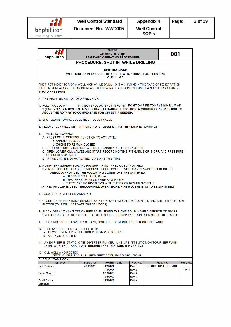
Well Control Standard Document No. WWD005
Appendix 4 Well Control
SOP’s
Page: 3 of 19
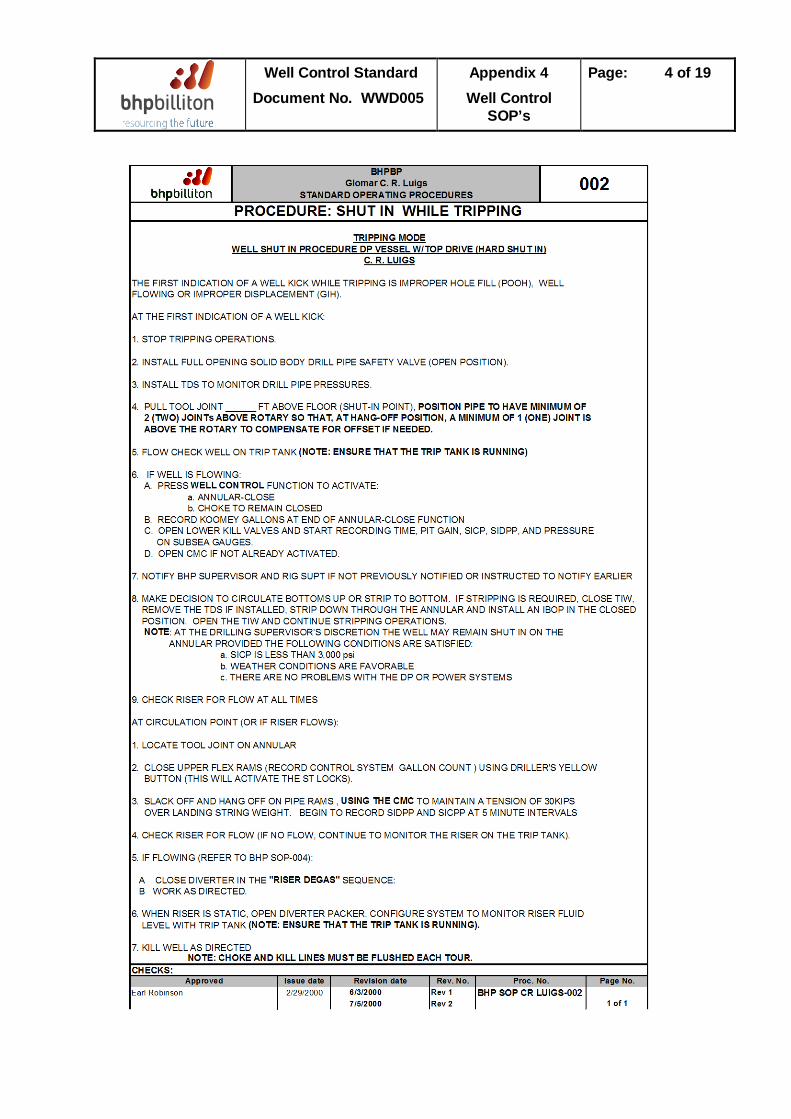
Well Control Standard Document No. WWD005
Appendix 4 Well Control
SOP’s
Page: 4 of 19
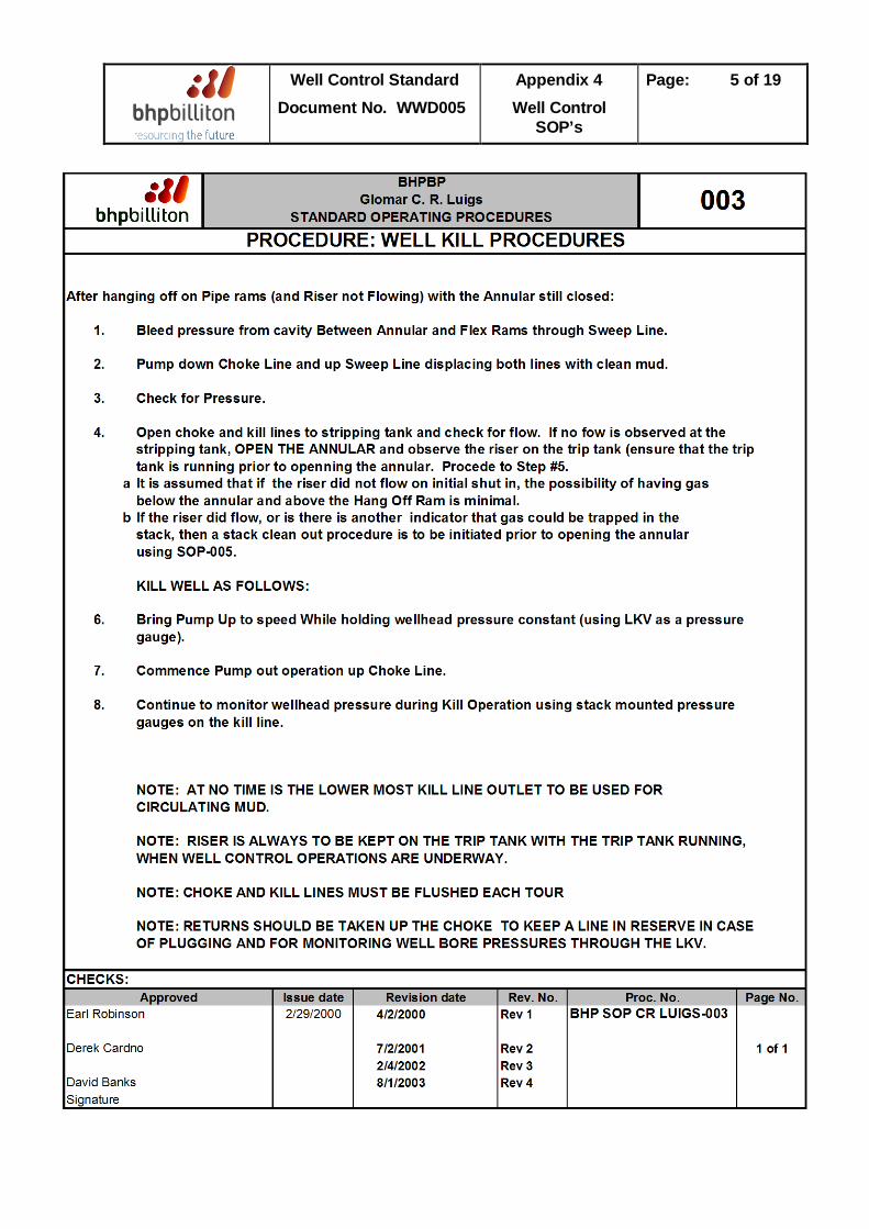
Well Control Standard Document No. WWD005
Appendix 4 Well Control
SOP’s
Page: 5 of 19
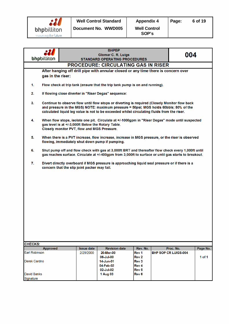
Well Control Standard Document No. WWD005
Appendix 4 Well Control
SOP’s
Page: 6 of 19
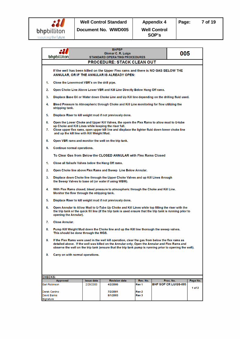
Well Control Standard Document No. WWD005
Appendix 4 Well Control
SOP’s
Page: 7 of 19
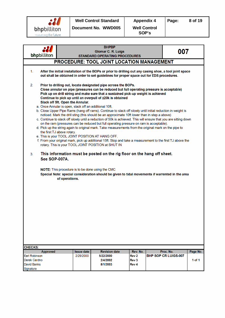
Well Control Standard Document No. WWD005
Appendix 4 Well Control
SOP’s
Page: 8 of 19
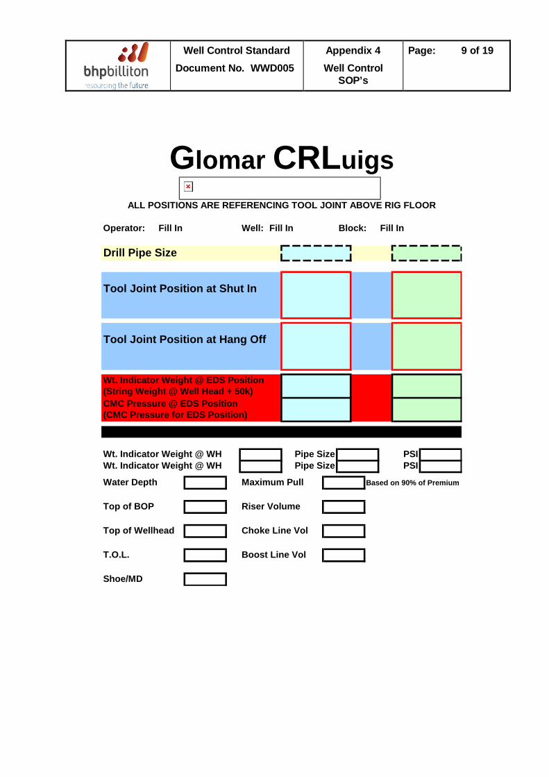
Well Control Standard Document No. WWD005
Appendix 4 Well Control
SOP’s
Page: 9 of 19
Operator: Fill In Well: Fill In Block: Fill In
Drill Pipe Size
Tool Joint Position at Shut In
Tool Joint Position at Hang Off
Wt. Indicator Weight @ EDS Position(String Weight @ Well Head + 50k)CMC Pressure @ EDS Position(CMC Pressure for EDS Position)
Wt. Indicator Weight @ WH Pipe Size PSIWt. Indicator Weight @ WH Pipe Size PSI
Water Depth Maximum Pull Based on 90% of Premium
Top of BOP Riser Volume
Top of Wellhead Choke Line Vol
T.O.L. Boost Line Vol
Shoe/MD
Glomar CRLuigsALL POSITIONS ARE REFERENCING TOOL JOINT ABOVE RIG FLOOR
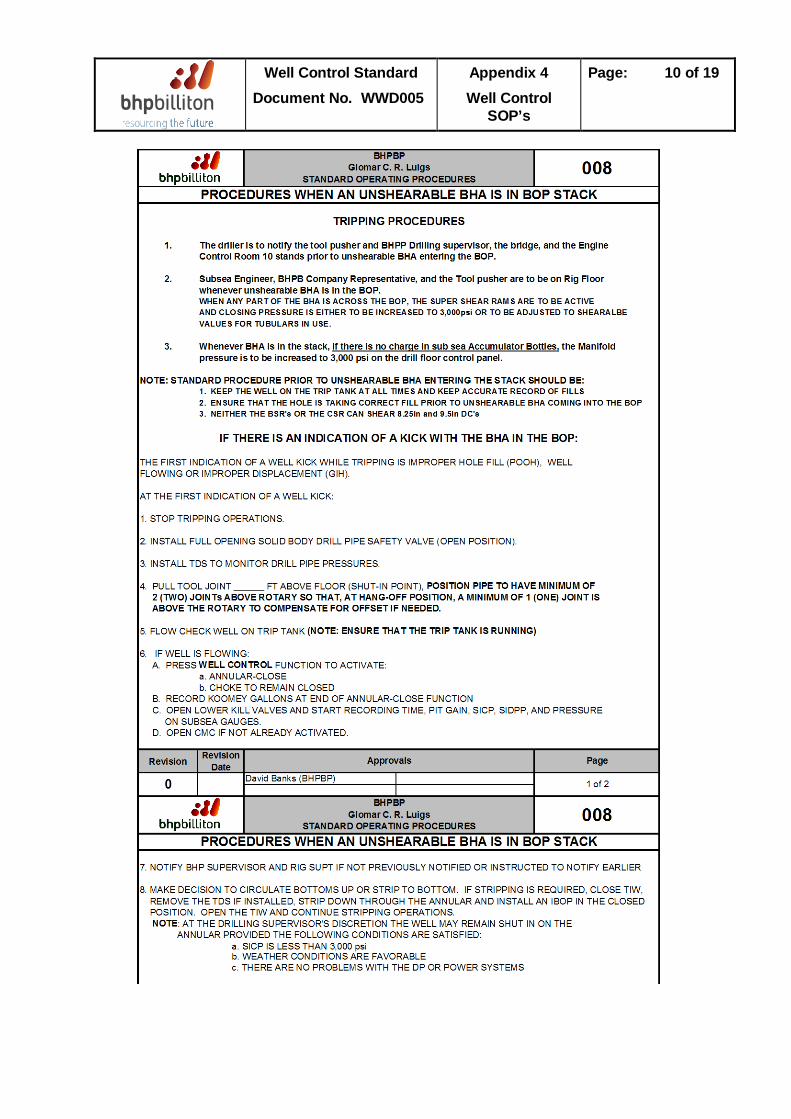
Well Control Standard Document No. WWD005
Appendix 4 Well Control
SOP’s
Page: 10 of 19
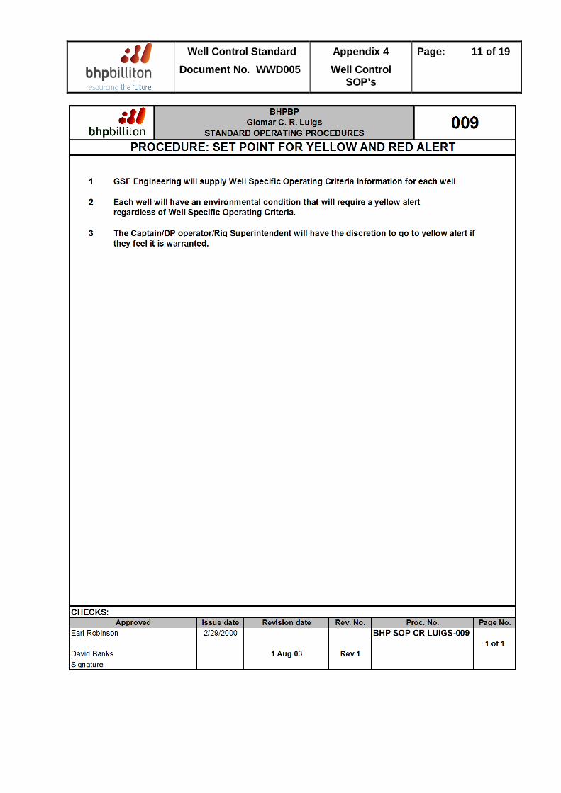
Well Control Standard Document No. WWD005
Appendix 4 Well Control
SOP’s
Page: 11 of 19
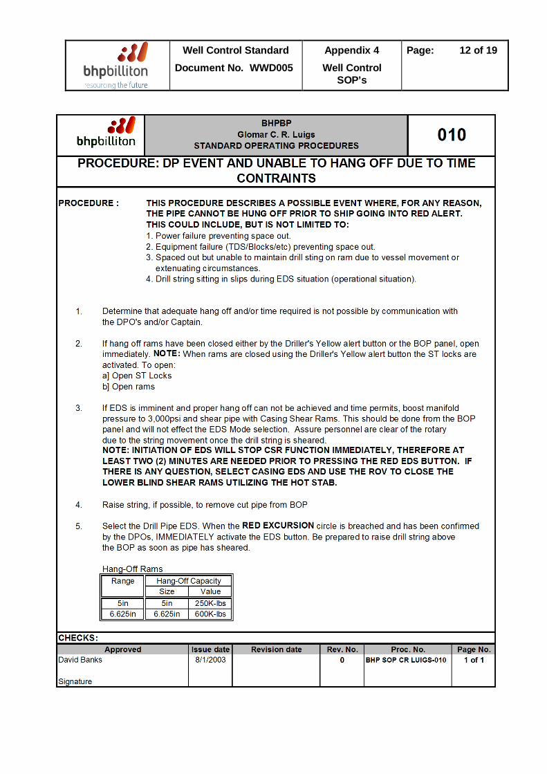
Well Control Standard Document No. WWD005
Appendix 4 Well Control
SOP’s
Page: 12 of 19
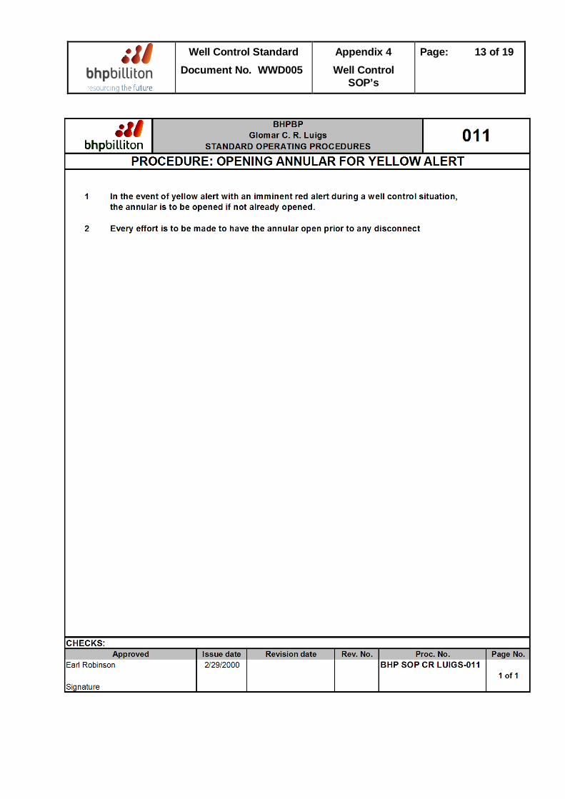
Well Control Standard Document No. WWD005
Appendix 4 Well Control
SOP’s
Page: 13 of 19
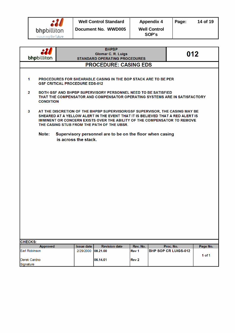
Well Control Standard Document No. WWD005
Appendix 4 Well Control
SOP’s
Page: 14 of 19
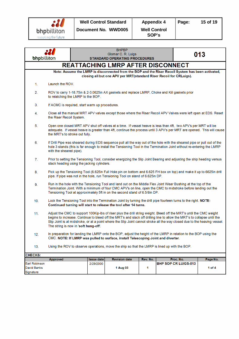
Well Control Standard Document No. WWD005
Appendix 4 Well Control
SOP’s
Page: 15 of 19
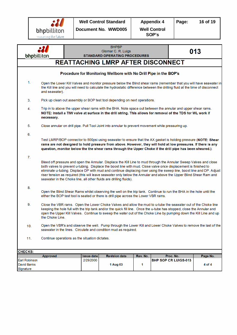
Well Control Standard Document No. WWD005
Appendix 4 Well Control
SOP’s
Page: 16 of 19
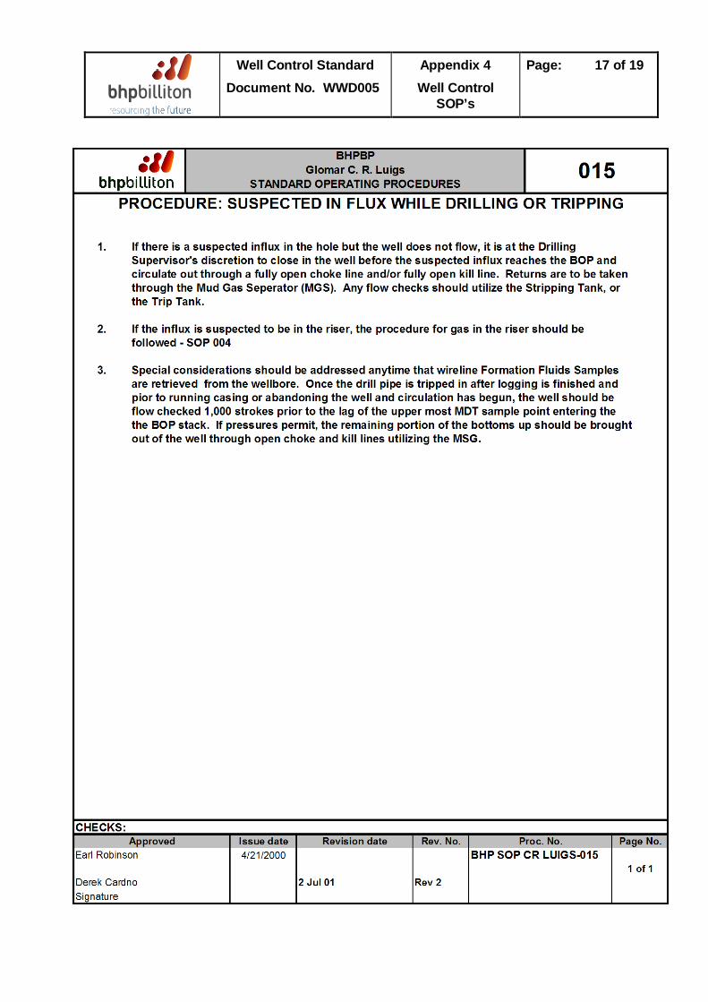
Well Control Standard Document No. WWD005
Appendix 4 Well Control
SOP’s
Page: 17 of 19
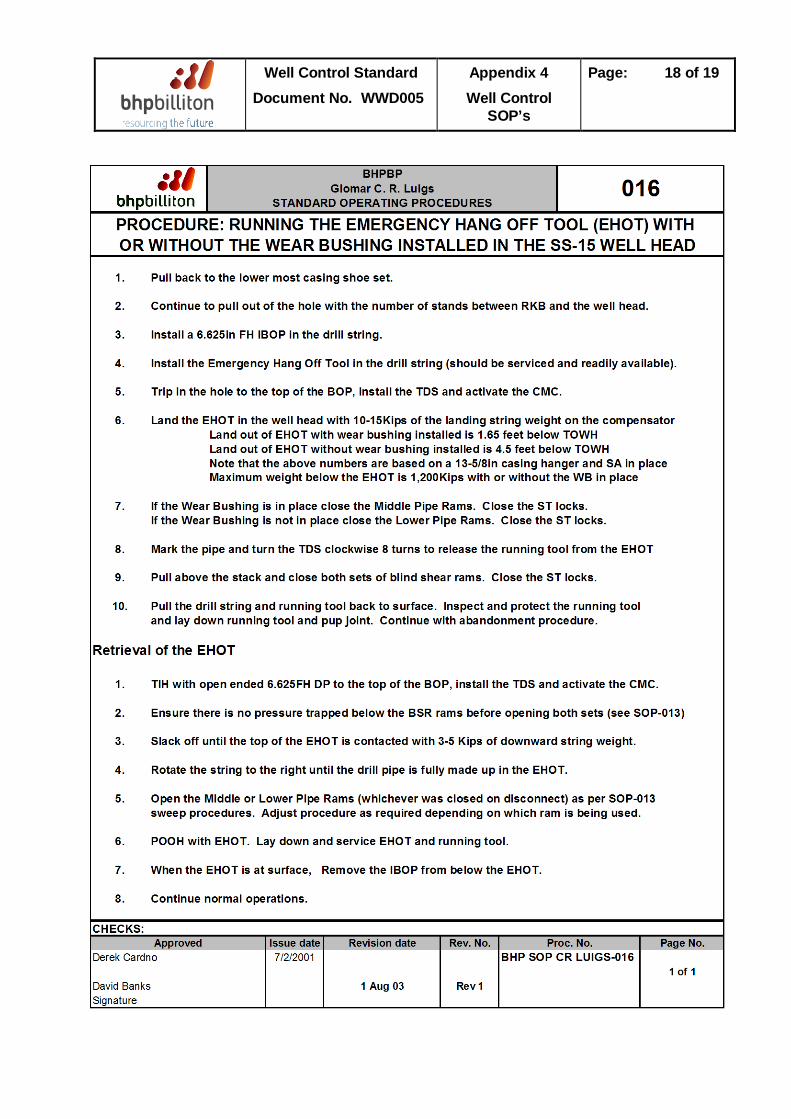
Well Control Standard Document No. WWD005
Appendix 4 Well Control
SOP’s
Page: 18 of 19
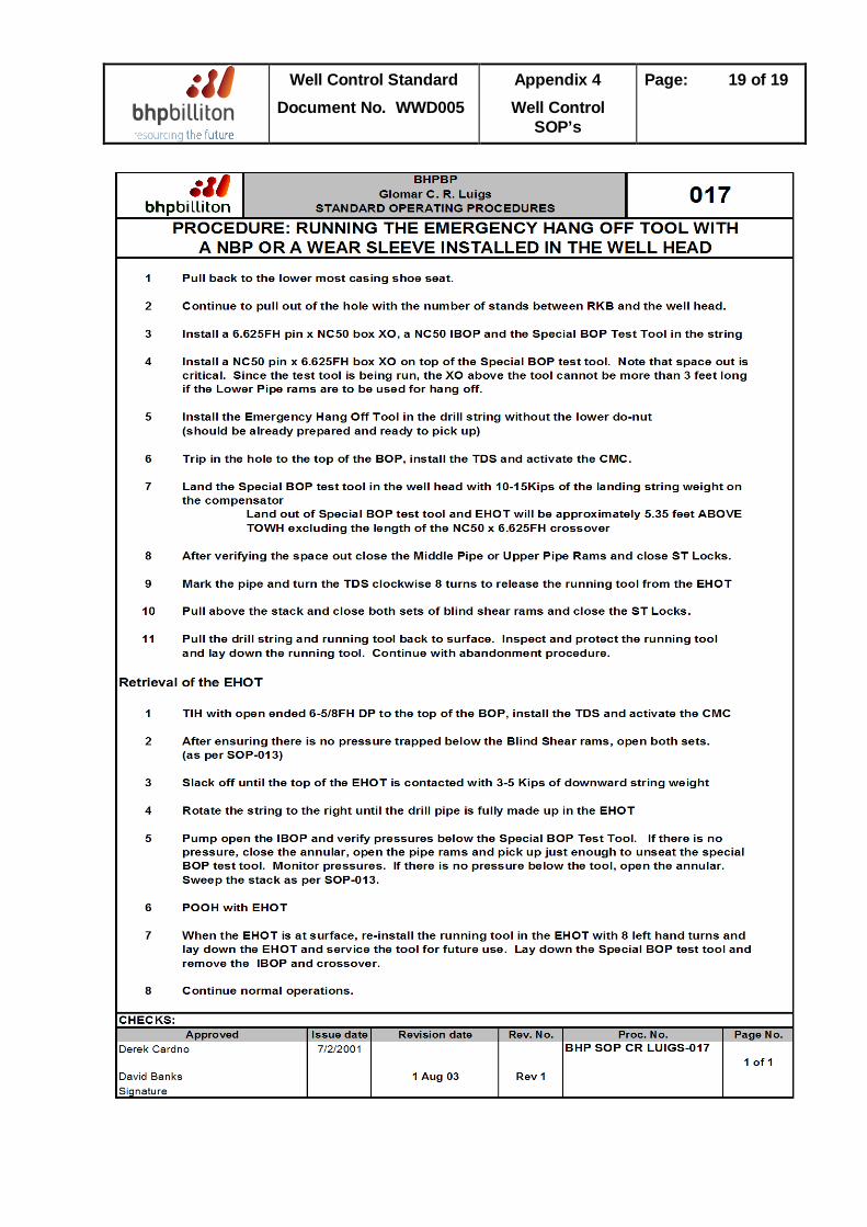
Well Control Standard Document No. WWD005
Appendix 4 Well Control
SOP’s
Page: 19 of 19