Embed Size (px)
Citation preview

m
sd
SEA.009.001.0743
DOCUMENT CONTROL (DEFINITION)
The process of controlling the development, issue and ongoing currency of controlled documents. It includes the need to identify and list recipients, ensuring accuracy of documents, regular review by owners, updating where necessary, systematic issuing of amendments and acknowledgement of their receipt, flow-on of charges to information from the original source to all copies, etc.
Preparation, Review, Approval
Prepares By (Custodian) Name Title DATE Mick Watters HSE MANAGER 26/06/2006
Reviewed By Name Title Date
Approved By Name TITLE Date
Registration and Distribution
DOCUMENT NAME DOCUMENT HOLDER COPY NO. Well Control Manual HSE Manager 1 Well Control Manual Operations Manager SD3, SD4, SD7 2 Well Control Manual Rig Manager SD 3 3 Well Control Manual Rig Supt SD 3 4 Well Control Manual Ops Manager SD 5 and SD 2 5 Well Control Manual Rig Manager SD 5 6 Well Control Manual Rig Supt SD 5 7 Well Control Manual Operations Manager SD 6 and SD 1 8 Well Control Manual Rig Manager SD 6 9 Well Control Manual Rig Supt SD 6 10 Well Control Manual Rig Manager SD 7 11
Well Control Manual Rig Supt SD 7 12 Well Control Manual OIM SD 4 13 Well Control Manual Safety Officer SD 4 14 Well Control Manual Safety Advisor SD1 15 Well Control Manual Rig Manager SD1 16 Well Control Manual OIM - West Triton 17 Well Control Manual Safety Advisor – West Triton 18 Well Control Manual Rig Manager – West Triton 19
SEA.009.001.0743
SEA.009.001.0744
Revision History
DATE PAGES REVISION REASON FOR UPDATE
26/06/06 All Rev June 06 Change of logo
16 Jan 07 All Rev June 06 Change of logo and updates
September 07 All Rev June 06 Amendments
SEA.009.001.0744

SEA.009.001.0745
Suggestions for Improvement
This document is a controlled document and conforms to Seadrill Document Control System. All users are encouraged to report items which either no longer comply with operational procedures or, where change would assist in ensuring the document fulfils its purpose. If you wish to submit such a change, please record your suggestion below, discuss it with your immediate supervisor for the area of operation concerned and submit it to the Custodian of the document.
SUGGESTION (specify section, page, revision no . . .)
Your Name: Job Title:
Rig Department: Date:
When complete, forward to :Document Custodian Seadrill Management Pte Ltd 10 Hoe Chiang Road #18-01 Keppel Towers Singapore 089315
SEA.009.001.0745
SEA.009.001.0746
Seadrill Well Control Manual
TABLE OF CONTENTS Page
1.0 PREPARATION................................................................ ................................................................ ........................ 9
1.1 RESPONSIBILITIES ................................................................................................................................ .................... 9 1.1.1 Offshore Installation Manager (OIM) ................................................................ ............................................... 9 1.1.2 Rig Superintendent/Toolpusher .......................................................................................................................... 9 1.1.3 Captain/Bargemaster ..................................................................................................................................... 9 1.1.4 Driller and Drill Crew ..................................................................................................................................... 10 1.1.5 Operator's Representative................................................................................................................................ 10 1.1.6 Third Party Employees ..................................................................................................................................... 10
1.2 PLANNING.............................................................................................................................................................. 11 1.2.1 The Well Control Plan................................ ................................................................ ...................................... 11
1.3 WELL CONTROL DRILLS ................................ ........................................................................................................ 12 1.3.1 Purpose of Well Control Drills ........................................................................................................................ 12 1.3.2 Kick While Tripping ................................................................................................................................ ......... 12 1.3.3 Kick While Drilling (On Bottom) ..................................................................................................................... 13 1.3.4 Kick while Drilling (Off Bottom - Shut in Well)............................................................................................... 13 1.3.5 Choke Drill....................................................................................................................................................... 14 1.3.6 Diverter Drill ................................................................................................................................................... 15 1.3.7 Stripping Drill ................................................................................................................................ .................. 15 1.3.8 Frequency of Drills .......................................................................................................................................... 16
1.4 PRE-RECORDED INFORMATION .............................................................................................................................. 16 1.4.1 Leak off/Formation Integrity Tests................................................................................................................... 17 1.4.2 Slow Circulating Rate ................................ ................................................................ ...................................... 18 1.4.3 Choke Line Friction ................................................................................................................................ ......... 19 1.4.4 Methods for Measuring Choke Line Friction Pressure (CLFP) ................................ ...................................... 21
2.0 PREVENTION................................ ........................................................................................................................ 22
2.1 RESPONSIBILITIES ................................................................................................................................ .................. 22 2.1.1 Offshore Installation Manager (OIM) ................................................................ ............................................. 22 2.1.2 Rig Superintendent/Toolpusher ........................................................................................................................ 22 2.1.3 Bargemaster ..................................................................................................................................................... 22 2.1.4 Driller and Drill Crew ..................................................................................................................................... 22 2.1.5 Operator's Representative................................................................................................................................ 23 2.1.6 Third Party Employees ..................................................................................................................................... 23
2.2 PLANNING.............................................................................................................................................................. 23 2.2.1 Well Planning ................................................................................................................................................... 23 2.2.2 Casing Design ................................................................................................................................ .................. 23
2.3 PRIMARY WELL CONTROL ..................................................................................................................................... 24 2.3.1 The Drilling (or Completion) Fluid ................................................................................................................. 24 2.3.2 Control of Lost Circulation .............................................................................................................................. 24 2.3.3 Use of Pit Volume Totaliser (PVT)................................................................................................................... 24
2.4 PREVENTATIVE PROCEDURES ................................................................................................................................ 24 2.4.1 Failure to Keep the Hole Full .......................................................................................................................... 24 2.4.2 Swabbing ................................ .......................................................................................................................... 25 2.4.3 Surging ................................................................ ................................................................ ............................. 25
3.0 WARNING SIGNS................................................................................................................................ .................. 26
3.1 RESPONSIBILITIES ................................................................................................................................ .................. 26 3.1.1 Offshore Installation Manager (OIM) ................................................................ ............................................. 26 3.1.2 Rig Superintendent/Toolpusher ........................................................................................................................ 26 3.1.3 Driller and Drill Crew ..................................................................................................................................... 26
4
SEA.009.001.0746

SEA.009.001.0747
Seadrill Well Control Manual
3.1.4 Operator's Representative................................................................................................................................ 26 3.1.5 Third Party Employees ..................................................................................................................................... 26 3.1.6 General ................................................................ ................................................................ ............................. 27
3.2 DRILLING BREAK................................................................................................................................................... 27 3.3 INCREASED RETURNS FLOW RATE................................................................................................ ......................... 27 3.4 PIT GAIN................................................................................................................................................................ 28
3.4.1 Pit Gain - While Drilling................................................................................................ .................................. 28 3.4.2 Pit Gain - During a Connection....................................................................................................................... 28
3.5 GAS CUT MUD....................................................................................................................................................... 29 3.5.1 Drilled Gas....................................................................................................................................................... 29 3.5.2 Connection Gas ................................................................................................................................ ................ 30 3.5.3 Trip Gas............................................................................................................................................................ 30 3.5.4 Gas Due to Inadequate Mud Density ................................................................ ............................................... 30
3.6 CHANGE IN PUMP SPEED OR PRESSURE ................................................................................................................. 30 3.7 INCORRECT HOLE FILL DURING TRIP..................................................................................................................... 31
4.0 ACTION ON DETECTING INFLUX................................................................................................................... 32
4.1 RESPONSIBILITIES ................................................................................................................................ .................. 32 4.1.1 Offshore Installation Manager (OIM) ................................................................ ............................................. 32 4.1.2 Rig Superintendent/Toolpusher ........................................................................................................................ 32 4.1.3 Bargemaster ..................................................................................................................................................... 32 4.1.4 Driller and Drill Crew ..................................................................................................................................... 33 4.1.5 Operator's Representative................................................................................................................................ 33 4.1.6 Third Party Employees ..................................................................................................................................... 33
4.2 SHALLOW GAS....................................................................................................................................................... 34 4.2.1 Shallow Gas Precautions ................................ ................................................................................................. 34 4.2.2 Shallow Gas Procedures - Drilling With Riser.............................................................................................. 34 4.2.3 Shallow Gas Procedures - Drilling Without Riser................................................................ ......................... 36 4.2.4 Drilling Below "Surface Casing" ..................................................................................................................... 38
4.3 SHUT IN PROCEDURES - WHILE DRILLING.............................................................................................................. 38 4.3.1 Kick While Drilling .......................................................................................................................................... 38 4.3.2 Massive Fluid Losses ....................................................................................................................................... 38
4.4 SHUT IN PROCEDURES - WHILE OFF BOTTOM ........................................................................................................ 41 4.4.1 Kick While Tripping ................................................................................................................................ ......... 41
4.5 SHUT IN PROCEDURES - WHILE OUT OF THE HOLE ............................................................................................... 43 4.5.1 Kick While Out of the Hole .............................................................................................................................. 43
4.6 ACTIONS AFTER WELL IS SHUT IN ................................................................................................ ......................... 45 4.7 REPORTING WELL KICKS ................................ ............................................................................................... 45 5.1 RESPONSIBILITIES ................................................................................................................................ .................. 47
5.1.1 Offshore Installation Manager (OIM) ................................................................ ............................................. 47 5.1.2 Rig Superintendent/Toolpusher ........................................................................................................................ 47 5.1.3 Bargemaster ..................................................................................................................................................... 47 5.1.4 Driller and Drill Crew ..................................................................................................................................... 47 5.1.5 Operator's Representative................................................................................................................................ 47 5.1.6 Third Party Employees ..................................................................................................................................... 48
5.2 INTRODUCTION ................................................................ ................................................................ ...................... 48 5.3 PIPE ON BOTTOM ................................................................................................................................................... 48 5.4 PIPE OFF BOTTOM ................................................................................................................................ .................. 50
5.4.1 Pipe off Bottom (Drillpipe Through BOP) ....................................................................................................... 50 5.4.2 Pipe off Bottom (Drill Collars Through BOP)................................................................................................. 50 5.4.3 No Pipe in the Hole .......................................................................................................................................... 54
5.5 STRIPPING.............................................................................................................................................................. 56 5.6 WHILE RUNNING CASING (OR LINER) ................................ ................................................................ .................... 58 5.7 UNDERGROUND BLOWOUT ................................ ................................................................ .................................... 59
5.7.1 Flow to a Zone Above a High Pressure Zone................................................................................................... 59 5.7.1 Flow to a Zone Above a High Pressure Zone (Continued) .............................................................................. 64 5.7.2 Flow to a Zone Below a High Pressure Zone................................................................................................... 64
5
SEA.009.001.0747
Seadrill Well Control Manual
6
6.0 WELL KILL TECHNIQUES ................................................................................................................................ 65
6.1 RESPONSIBILITIES ................................................................................................................................ .................. 656.1.1 Offshore Installation Manager (OIM) ................................................................ ............................................. 656.1.2 Rig Superintendent/Toolpusher ........................................................................................................................ 656.1.3 Bargemaster ..................................................................................................................................................... 656.1.4 Driller and Drill crew ................................ ................................................................ ...................................... 666.1.5 Operator's Representative................................................................................................................................ 666.1.6 Third Party Employees ..................................................................................................................................... 66
6.2 GENERAL ................................................................ ............................................................................................... 666.2.1 Constant Bottomhole Pressure................................................................................................ ......................... 666.2.2 Calculations ..................................................................................................................................................... 67
6.3 THE WAIT AND WEIGHT METHOD ................................................................................................ ......................... 676.3.1 Description....................................................................................................................................................... 676.3.2 Pump Start Up ................................................................................................................................ .................. 686.3.3 Procedure ................................................................................................................................ ......................... 68
6.4 THE DRILLER'S METHOD ....................................................................................................................................... 686.4.1 Description....................................................................................................................................................... 686.4.2 Pump Start Up ................................................................................................................................ .................. 696.4.3 Procedure ................................................................................................................................ ......................... 69
6.5 VOLUMETRIC METHOD.......................................................................................................................................... 706.5.1 Description....................................................................................................................................................... 706.5.2 Procedure ................................................................................................................................ ......................... 71
6.6 BULLHEADING ....................................................................................................................................................... 716.7 BARITE/CEMENTPLUGS ................................ ........................................................................................................ 726.8 COMPLICATIONS DURING WELL CONTROL OPERATIONS........................................................................................ 73
6.8.1 Introduction................................................................ ................................................................ ...................... 736.8.2 Gas Migration ................................................................................................................................ .................. 736.8.3 Surface Equipment Problems ................................ ................................................................ ........................... 746.8.4 Sub-Surface Problems ................................ ................................................................ ...................................... 766.8.5 Emergency Disconnect from a Pressured Well ................................................................................................ 80
6.9 WELL CONTROL IN HORIZONTAL WELLS ................................................................ ............................................... 81
7.0 OIL BASED MUD................................................................................................................................................... 82
7.1 INTRODUCTION ................................................................ ................................................................ ...................... 827.2 EFFECTS OF SATURATION....................................................................................................................................... 83
7.2.1 Case I. Unsaturated Mixture ............................................................................................................................ 837.2.2 Case II. Saturated Mixture................................ ............................................................................................... 847.2.3 Case III. Over-saturated Mixture ..................................................................................................................... 84
7.3 COMPRESSIBILITY ................................................................................................................................ .................. 847.4 SUMMARY ................................................................ ................................................................ ............................. 84
8.0 JACKUP WELL CONTROL PROCEDURES ................................................................ .................................... 86
8.1 OBJECTIVE............................................................................................................................................................ 86
JACKUP WELL CONTROL PROCEDURES – DRILLING (FORM A) ............................................................ 89
JACKUP WELL CONTROL PROCEDURES – TRIPPING (FORM B) ................................ ............................. 90
SHALLOW GAS PROCEDURES - JACKUP ................................................................................................ .................. 92
SEADRILL JACKUPS WORKING WITH DIVERTERS .............................................................................................. 95
SEADRILL DIVERTING PROCEDURES - DRILLING................................................................................................ 97
SEADRILL JACKUP DIVERTING PROCEDURES - TRIPPING ................................ ............................................... 98
SEA.009.001.0748
SEA.009.001.0748
Seadrill Well Control Manual
7
WELL CONTROL TRAINING - JACKUP ................................ ................................................................ .................... 100
WAITING ON CEMENT - SURFACE STACKS ................................................................ ........................................... 103
WOC DECISION TREE ................................................................................................................................................... 107
WOC EVENT LOG ................................................................ ................................................................ ........................... 108
APPENDICES ................................................................ ................................................................ .................................... 110
APPENDIX A ..................................................................................................................................................................... 111
APPENDIX B................................................................ ...................................................................................................... 112
APPENDIX C ..................................................................................................................................................................... 113
** PLEASE NOTE THAT ON A JACK UP RIG THE DUTIES OF OIM AND RIG SUPERINTENDENT WILLBE THE SAME.
SEA.009.001.0749
SEA.009.001.0749
Seadrill Well Control Manual
8
INTRODUCTION
PURPOSE
The purpose of this manual is to provide a clear, easy to use reference document of SeaDrill (referredto as the Company) well control policy and both Company, and Rig specific well control procedures. Itis intended to provide personnel managing Company mobile offshore drilling units (MODU’s), anddrilling operations onboard Company installations, with an easy to use aid to well control and wellcontrol decision making.
This manual is not intended to replace well control teaching manuals, nor is it intended to absolvepersonnel with a well control function from the necessity of acting safely, exercising soundprofessional judgment, and following, at all times, "good oilfield practice".
The Company's drilling and other well related operations are designed, planned and conducted with theintention of maintaining primary, or hydrostatic, well control. While an installation is engaged in welloperations, the drill floor will be manned at all times by a Company employees with a minimum wellcontrol qualification required by the relevant authorized bodies in the area of operation. IWCF will bethe standard used.
Where primary well control has, for whatever reason, been lost, it is the responsibility and duty of theDriller to act as quickly as is safely possible to instigate secondary well control, normally by shuttingan element of the blowout preventer. The Company's preferred method is the "fast shut in method",unless modified, for a specific period, by bridging documents.
Where well kill procedures involving circulation are necessary, one of the forms of constant bottomhole pressure method will be used. If for some reason constant bottom hole pressure methods ofkilling a well are not immediately possible, operations should be directed towards arriving at a positionwhere constant bottom hole pressure methods are achievable.
SEA.009.001.0750
SEA.009.001.0750

Seadrill Well Control Manual
9
1.0 PREPARATION
1.1 RESPONSIBILITIES
1.1.1 Offshore Installation Manager (OIM)
The OIM has, at all times, the ultimate responsibility for all operations carried outonboard the installation. To prepare the installation and its crew for well controloperations he must ensure that those he appoints to positions with responsibility for wellcontrol are trained and competent to fulfil those responsibilities, and familiar with theinstallation’s well control equipment.
The OIM is responsible for ensuring that the installation's well control equipment issupplied "fit for purpose" and maintained in this condition.
The OIM is responsible for maintaining and implementing the installation's WellControl Plan as defined in the Company's Well Control Procedures and the CompanyEmergency Response Manual. He will call on the assistance of all other members of thevessel's crew to assist in the development and implementation of the plan.
1.1.2 Rig Superintendent/Toolpusher
The Rig Superintendent/Toolpusher, as the person in charge of drilling operations, isresponsible to the OIM for the maintenance of well control on wells drilled, completed,worked over, suspended or abandoned by the installation.
The Rig Superintendent/Toolpusher will be called on to assist the OIM in thedevelopment and implementation of the installation's Well Control Plan.
To prepare for well control operations, the Rig Superintendent/Toolpusher is responsiblefor instructing and exercising the crew in their well control duties and ensuring that allwell control equipment, including blow-out preventers, mud circulating, mud monitoringand mud conditioning equipment, are maintained in a "fit for purpose" condition.
1.1.3 Captain/Bargemaster
The Captain / Bargemaster, as person in charge of marine operations on the installation,has the responsibility of cooperating in the development of the installation's well controlplanning in general and "move off" planning in particular.
In any well control situation, the Bargemaster will have particular responsibility forlogistics, forward planning and weather forecasting. It will be his responsibility tomonitor, present and forecast weather conditions and advise the OIM and RigSuperintendent/Toolpusher on predicted vessel motion and evacuation capabilities.
SEA.009.001.0751
SEA.009.001.0751

Seadrill Well Control Manual
10
It will be the Bargemaster's responsibility to assist the OIM in the formulation of"precautionary evacuation" plans and, if necessary, the implementation of those plans.
1.1.4 Driller and Drill Crew
The Driller is to be in direct control of drilling operations, must ensure that he and hiscrew exercise their well control duties, as directed by the Rig Superintendent/Toolpusher, so as to become, and remain, familiar with the actions to be taken ondetection of a well control problem.
The Driller will be required by the OIM to assist the Rig Superintendent/Toolpusher inthe development and implementation of the installation's Well Control Plan.
The Driller is responsible for maintaining and updating "pre kick data" and taking andreporting "slow circulating rates", at specified intervals.
It is the Driller's responsibility to check that safety valves and all equipment required formonitoring and recording drilling fluid volumes, flow rates, pump speed and casing, anddrill pipe pressures is in a serviceable condition and ready for immediate use. He has aduty to immediately report any deficiencies found to the Rig Superintendent/Toolpusher.
1.1.5 Operator's Representative
The Operator's Representative has a responsibility to the OIM to provide specialistadvice on well control. He has a duty to make available to the OIM and the RigSuperintendent/Toolpusher any information about the operating area, such as, offsetwell data, seismic data or any other relevant information in his, or his Company's,possession. This is of vital importance, particularly in the planning stages, for the safetyof the operation, personnel, installation and the environment.
The Operator's Representative has a duty to participate fully in the development of theinstallation's Well Control Plan for the specific location. The Operators Representativewill also have a responsibility to oversee and assist in well control drills, as per section1.3.
1.1.6 Third Party Employees
Certain "Third Party" employees may also have well control functions. Althoughtypically employed under contract to the Operator, and reporting directly to theOperator's Representative, they will be appointed by the OIM to assist in thedevelopment, and possible implementation of the installation's Well Control Plan.
The following positions, and any others required by the OIM, are normally involved informulation of the well control plan and if necessary the plan's execution:-
Mud engineers Mud Loggers
SEA.009.001.0752
SEA.009.001.0752
Seadrill Well Control Manual
11
Cementers
1.2 PLANNING
1.2.1 The Well Control Plan
The OIM, with the assistance of the Rig Superintendent/Toolpusher, the Operator'sRepresentative and whomever else he calls upon, will develop a "Well Control Plan".This plan will seek to cover, in as much detail as required, all well control eventualities,which can be foreseen for the particular well.
The purpose of the plan will be to clarify, for all those involved in well controloperations, the duties and actions required of them.
The Well Control Plan must, as a minimum, cover the following topics:-
1.2.1.1 Crew Positions and Duties during Well Control Operations
Specific actions to be taken in the event of a loss of primary well control. TheCompany's drill crews will be well practiced in their normal functions during aloss of primary well control. The plan should stress any variations from the"normal", and ensure that second and third party personnel are aware of theduties required of them.
1.2.1.2 Well Control Decision Making
Advice and assistance, in the form of flow charts, to simplify well controldecision making.
1.2.1.3 Well Control Logistics
To clarify the detail of how things are going to be accomplished and howproblems are going to be overcome. Possible headings in this section might be"communications", "barite supplies", etc.
1.2.1.4 Pre-kill Meetings
To specify who will attend planning meetings once a well control problem hasbeen identified.
1.2.1.5 H2S Contingency
Contingency plans for actions to be taken on detection of H2S gas. (Refer tothe Company's Emergency Response Manual).
1.2.1.6 Pollution Control/Damage Limitation/Loss Management
SEA.009.001.0753
SEA.009.001.0753
Seadrill Well Control Manual
12
To set out available pollution control options. These should include operatorsupplied pollution control equipment and how to call out pollution controlsupport.
1.3 WELL CONTROL DRILLS
1.3.1 Purpose of Well Control Drills
The purpose of BOP (Well Control) Drills is to familiarise the participants with techniques thatmay be implemented in the event of a kick.
One of the major factors which influence the wellbore pressures after a kick is taken is the volumeof the influx. The smaller the influx, the less severe will be the pressures during the well killoperation. In this respect, it is important that the drill crew react quickly to any sign that an influxmay have occurred, and promptly execute the prescribed control procedure. Drills should bedesigned to reduce the time that the crews take to implement these procedures.
The relevant Drills should be carried out as often as is necessary, and as often as well conditionspermit, until the Drilling Supervisors, (both Company and Operator), and the OIM are satisfied thatevery member of the drill crew is familiar with the entire operation.
Every effort must be made to ensure that drills are carried out in the most realistic manner possible.Where practical, there should be no difference between drills and actual control procedures.
Once satisfactory standards have been achieved, the drills should be held at least once per week. Ifstandards fall unacceptably, the Drilling Supervisors or OIM should stipulate that the Drills areconducted more frequently.
1.3.2 Kick While TrippingThe purpose of this drill is to familiarise the Driller and crew with the shut-in procedure that willbe implemented in the event of a kick during a trip. This drill should only be conducted when thebit is inside the shoe of the last casing string.
1. Set slips.
2. Install the (open) drill pipe safety valve and close.
3. Close annular preventer (at reduced annular pressure).3a. Ensure choke/kill manifold is closed.3b. Open BOP upper outer, and inner choke valve.
4. Check well is shut in. Check pre-calculated BOP space out - increase annular pressure andfull operating pressure.
5. Pick up a stand of drill pipe and make up top drive. (Activate DSC).
6. Notify Rig Superintendent/Toolpusher & Operator's Representative that the well is shut-in.
7. Line up standpipe manifold.
8. Open safety valve and record pressures.
SEA.009.001.0754
SEA.009.001.0754

Seadrill Well Control Manual
13
9. Stop other operations.
With reference to Paragraph 1.3.1 (ii) the vital sections of this drill are steps 1-3. It will not benecessary to complete each step (1-9) of the drill each time it is performed, but it isrecommended that steps 1-3 are practiced once a trip.
It is expected that steps 1-3 will take about 60 seconds.
Performance of the complete drill (steps 1-9) should take less than 15 min.
1.3.3 Kick While Drilling (On Bottom)
The purpose of this drill is to familiarise the crew with the control procedure that will beimplemented in the event of a kick while drilling. This drill may be conducted either inopen or cased hole. However, if the drill is conducted with the drill string in open hole,the well will not be shut-in.
Without prior notice, the Rig Superintendent/Toolpusher gradually increases theapparent pit level by manually raising the float or transferring mud to give an apparentfluid gain.
The Driller is expected to detect the pit gain and take the following steps:-
1. Pick up the drill string until the tool joints clear the BOP. (Space out in accordancewith the pre-recorded space out data).
2. Shut down the pumps.
3. Check the well for flow.
4. (See item 1.3.2 above). Close annular preventer.
5. Record the time required for the crew to react and conduct the drill on the IADCdrilling report.
It is expected that steps 1-3 will take about 2 minutes.
Performance of the complete drill (steps 1-5) should take approximately 10 minutes.
1.3.4 Kick while Drilling (Off Bottom - Shut in Well)
When the bit has been tripped to the previous casing shoe, a further drill may beconducted which will result in the well being shut-in.
After tripping the bit to the shoe, the following procedure may be used as a guideline forthis drill:-
SEA.009.001.0755
SEA.009.001.0755
Seadrill Well Control Manual
14
Stop tripping operations, install the top drive and start circulating.
Having been instructed to do so by the Rig Superintendent/Toolpusher, the Drilleris expected to take the following steps to shut-in the well:-
1. Pull up until the tool joint clears the BOP’s. (Space out in accordance with pre-recorded space out data).
2. Shut down the pumps.
3. (See item 1.3.2). Close the annular preventer.
4. Check well is shut in.
5. Record the casing and drill pipe pressure.
6. Notify Rig Superintendent/Toolpusher the well has been shut in.
7. Double check space out, close and lock hang-off rams, hang-off pipe and openannular.
8. Record the time taken for the crew to shut-in the well on the IADC drillingreport.
Performance of the complete drill (steps 1-5) should take ± 10 minutes.
1.3.5 Choke Drill
The objective of this drill is to give drill crews the most realistic type of well controltraining and a feel for the equipment and procedures which they would use to kill a well.
This drill should be carried out prior to drilling out the intermediate and productioncasing strings. It should never be carried out when open hole sections are exposed. Thefollowing procedure is recommended:-
1. Run in hole and tag the top of cement.
2. Pull back one stand and install the top drive.
3. Break circulation and establish slow circulating rate pressures. (Considercirculating bottoms up prior to this if the annulus may contain contaminated mud).
4. Carry out standard BOP drill (kick while drilling), resulting in the well beingshut-in.
5. Consider applying low pressure to the casing (typically 200psi), bring the pump upto kill speed controlling the drill pipe pressure according to a predeterminedschedule.
SEA.009.001.0756
SEA.009.001.0756

Seadrill Well Control Manual
15
A drill pipe pressure schedule should be drawn up before the drill takes place andcarefully adhered to.
It is important that the choke operator develops a feel for the lag time betweenmanipulation of the choke and its subsequent effect on the drill pipe pressure. The lagtime should be recorded, so that it can be used for reference, should a kick be taken inthe next hole section.
It is important that this opportunity to circulate across a choke is used to maximumeffect.
Note: Ensure mud pump pressure relief valves are set well below casing burstpressure before exercise takes place and re-set after exercise is complete.
1.3.6 Diverter Drill
Due to the historic unreliability of diverter systems it has become the Company's policythat "Shallow Gas" kicks, once the marine riser and BOP have been run, WILL BESHUT IN. Despite this fact, since all the Company's installations are fitted with adiverter system, the following comments are included:-
The objective of this drill is to minimise the Driller and drill crew's reaction time,while ensuring that all the diverter system and equipment is in good working order.
The time taken for each diverter function to operate should be recorded.
A drill should be carried out prior to drilling out of the surface casing.
Rig specific shallow gas procedures are covered in the Company EmergencyResponse Manual and, if required by a particular contract, bridging documents.
Diverter drills should be designed in line with the relevant Rig specific procedure,which will be adopted in the event of a shallow gas kick, and be held as part of thebroader shallow gas drills that are usually held before spudding in.
1.3.7 Stripping Drill
The objective of this drill is to give drill crews the most realistic type of well controltraining and a feel for the equipment and procedures which they would use to strip into awell under pressure.
This drill should be carried out prior to drilling out the intermediate and productioncasing strings. It should never be carried out when open hole sections are exposed. Thefollowing procedure is recommended:-
1. Run in hole and tag the top of cement.
SEA.009.001.0757
SEA.009.001.0757

Seadrill Well Control Manual
16
2. Pull back several stands and install a "Gray" valve or some other non-return valve.
3. Break circulation and establish slow circulating rate pressures. (Considercirculating bottoms up, prior to this, if the annulus may contain contaminated mud).
4. Carry out standard BOP drill (kick while tripping), resulting in the well beingshut-in.
5. Apply low pressure to the casing (typically 200 - 400psi).
6. Strip into the well through the upper annular, bleeding off specified volume of fluidafter each stand, to bring the annulus pressure back the pressure applied in step 5.
7. Pre-calculated stripping sheet should be available for comparison.
It is important that the choke operator develops a feel for bleeding off small volumes offluid in to the stripping tank, and that as many operators as possible get a chance to trainon the equipment, as this drill will not be performed often.
Note: Ensure mud pump pressure relief valves are set well below casing burstpressure before exercise takes place and re-set after exercise is complete.
1.3.8 Frequency of Drills
1. Kick while Tripping 1 BOP Drill Every Trip (once string is insidecasing)
2. Kick while Drilling 1 Pit Drill Every Tour that includesdrilling operations.
3. Choke Drill 2 After every suitable casing string isrun and cemented.
4. Diverter Drill 2 After surface casing - Once perwell.
5. Stripping Drill 2 As agreed with client, after suitable casingstring is run and cemented.
1 The drills are to involve Mud Loggers.2 These drills will be held with the Operator's Representative in attendance.
All drills to be recorded in the IADC report with times included for items 1 & 2.
1.4 PRE-RECORDED INFORMATION
SEA.009.001.0758
SEA.009.001.0758

Seadrill Well Control Manual
17
In order to initiate proper well control procedures quickly and effectively, information must beassembled and organised prior to well control problems arising.
The following data is required:-
1. Maximum Allowable Casing Pressure.2. Casing shoe depth. Both TVD & MD3. Hole depth - Measured Depth.4. Hole depth - True Vertical Depth.5. Drill string capacity.6. Annular capacity.7. Slow Circulating Rates/pressures.8. Pump displacement.9. Mud weight.10. Casing OD, ID, Grade and Burst Pressure11. Choke line capacity.12. Choke line length.13. Choke Line Friction.
For ease of organisation and use, several formats of "Well Control Kill Sheet" are available.The Company's version is in appendix B.
The pre-recorded information will be updated at least every 24 hr. If there are rapid changes incritical values, the sheet will be updated more often.
1.4.1 Leak off/Formation Integrity Tests
Fracture GradientThe fracture gradient reflects the minimum pressure at which a formation will rupture orexisting fractures will be extended. The rupture or fracture pressure is usually expressedas a mud weight (in pounds per gallon) which will cause loss of circulation.
Generally, fracture gradients increase with depth. This usually means that the weakestpart of the well is at the last casing seat. The best way to determine the fracture gradientis to run a "leak-off test" after casing is set and cemented. The pressure obtained fromsuch a test can be used to determine how much back pressure can be held against thispoint during a well kill procedure (Maximum Allowable Casing Pressure).
This information is important and must be posted with maximum allowable annularpress, for easy access along with other pre-recorded information.
Conducting Leak off/Formation integrity tests
Different techniques are available for running pressure integrity tests but, regardless ofthe method used, certain general points apply to all. For example, an accurate pressure
SEA.009.001.0759
SEA.009.001.0759

Seadrill Well Control Manual
18
gauge is required, a cementing pump (instead of the mud pump) is to be used, the pumprate should not exceed 1/4 bbl per minute (bpm) and, as previously mentioned, "new "hole below the casing shoe should be limited to 15 ft.
To conduct a formation integrity test, the recommended procedure is:-
1. Circulate the hole to establish a uniform mud density throughout the system.
2. Pull the bit into the casing shoe.
3. Rig up circulating head, secure same and pressure test lines.
4. Close the blowout preventer.
5. Using the cement pump, pump down the drill string at a rate of about 1/4 bpm.
6. On a graph, plot the fluid pumped in 1/4 bbl increments versus drill pipe pressureuntil the formation at the shoe starts to take fluid; at this point, the pressure willcontinue to rise, but at a slower rate.
7. Repeat the test to verify the point at which the formation just starts to take fluid -this point is leak-off pressure
Note: If a float is run in the string annulus pressure must be bled off through thechoke prior to opening the annular preventer.
Leak off pressure (MACP) is converted to an "Equivalent Mud Weight"
1.4.2 Slow Circulating Rate
Slow Circulating RateSlow Circulating Rates, sometimes referred to as Slow Pump Rates or Kill Rates areused as a reference point in well killing operations.
Circulating PressureCirculating pressure is the pump pressure required to overcome friction between thedrilling fluid and whatever it contacts as it moves down the drill string, through the bit,and up the annulus.
Circulating pressure varies with mud properties (particularly mud weight, viscosity andcold Oil Based Muds), the length and size of the drill string, the size of nozzles in thedrill bit, annular clearance and the rate of circulation.
To maintain valid readings, for slow circulating rate figures, it is necessary to take freshreadings whenever one of the parameters mentioned above changes.
Take new slow circulating rates with all pumps when one of the following happens:-
SEA.009.001.0760
SEA.009.001.0760
Seadrill Well Control Manual
19
1. Mud weight change of >0.1ppg. (Once new mud weight is even all the wayaround).
2. When back on bottom with a new bit. (Once bottoms up has passed).
3. When making rapid progress drilling.
4. Every 12 hours.
5. Following pump repairs.
Slow circulating rates will be taken with the pump, which would be used to kill thewell, using the gauges that the pump operator and choke operator would be using duringthe kill operation.
Rates will be as agreed with the Rig Superintendent and may be expressed either as apump speed, (e.g., 20 strokes per minute) or a flow rate, (e.g., 1 bbl/min).
SCR results will be recorded in an agreed place for the Driller's ready use with the mostrecent reading used in the daily update of the "Well Control Kill Sheet". SCR resultsshould also be recorded on the IADC report.
1.4.3 Choke Line Friction
An effect of using small diameter choke and kill lines to handle high pressure fluids isthe increased pressure required to move the fluids through the smaller lines due toincreased friction.
This choke line friction pressure does not show up on the choke gauge but does have aneffect on the wellbore. Because this pressure from choke line friction (CLF) is feltdownhole by the wellbore, allowance for it must be made during a kill circulation.
Ignoring CLF during pump start up, when the choke gauge is used instead of the drillpipe pressure gauge, will put additional pressure on the well equal to the CLF. Thisadditional pressure could lead to breakdown of the casing shoe or formation.
Choke line friction increases with:-
1. An increase in choke line length.2. An increase in mud weight and/or viscosity.3. An increase in pumping rate.4. With a decrease in choke line inside diameter.
In deep water, due to the long choke line lengths, this pressure can easily exceed theequivalent of ½ ppg mud weight at slow pump rates.
Knowing choke line friction and understanding its relationship to bottom hole pressureis the most important difference between "Normal" and "Deep Water" well control.
SEA.009.001.0761
SEA.009.001.0761
Seadrill Well Control Manual
20
Ignoring the effects of choke line friction can lead to a loss of well control either byallowing additional influx of formation fluids or by breakdown of the casing shoe orformation.
SEA.009.001.0762
SEA.009.001.0762

Seadrill Well Control Manual
21
1.4.4 Methods for Measuring Choke Line Friction Pressure (CLFP)
At least three slow circulating rates must be taken in two steps:-
Basic Method:-
1. Pump at the desired rate down the drill string, up the annulus.Record the rates and circulating pressures (example 200psi @ 30spm).
2. Pump, at the same rates as in step 1, down the drill string and up annulus against aclosed BOP and up the choke line to poor boy degasser.Record the rates and circulating pressures (example 300psi @ 30spm).
CLFP is the pressure to circulate through the choke and/or kill line minus the pressure to circulatethrough the hole, i.e., 100psi @ 30spm (2 - 1)
Alternate Method:-
1. Pump down choke line and up the riser. Record the rates and circulating pressure.
2. Pump down choke line and up kill line. Record the rates and circulating pressure.
The CLP at a given rate would be the pressure difference between the recordings for the ratesin 1 and 2.
Because CLF acts on the well but does not show up on the casing pressure gauge,allowance for it must be made during pump start-up.
SEA.009.001.0763
SEA.009.001.0763

Seadrill Well Control Manual
22
2.0 PREVENTION
2.1 RESPONSIBILITIES
2.1.1 Offshore Installation Manager (OIM)
The OIM has the responsibility of ensuring that all operations onboard the installationare carried out according to agreed plans and procedures and measures to guard againstloss of primary well control are implemented at all times.
The OIM will rely on the Rig Superintendent/Toolpusher and Operator'sRepresentative(s), as drilling professionals, to guide him in his final decision making.
2.1.2 Rig Superintendent/Toolpusher
The Rig Superintendent/Toolpusher is responsible to the OIM for the safe, efficient, andcost effective management of drilling operations onboard the installation.
The Rig Superintendent/Toolpusher has the responsibility of planning, directing, andcontrolling drilling operations to ensure that they are conducted in as safe a manner as isreasonably practicable. In particular, the Rig Superintendent/Toolpusher is responsiblefor supervising the maintenance of primary well control by the constant monitoring ofdrilling fluid properties, fluid volumes and return flow rates so that imminent or actualloss of primary well control is prevented, or minimised and contained.
2.1.3 Bargemaster
The Bargemaster, as manager of marine operations onboard the installation, has theresponsibility of cooperating with the Rig Superintendent/Toolpusher in planning toprevent loss of primary well control. His responsibilities will be mainly concerned withlogistics, weather forecasting and ensuring that the marine crew are exercised in theirwell control functions.
2.1.4 Driller and Drill Crew
The Driller, as the person in direct control of drilling operations, has the responsibilityfor the maintenance of primary well control by the constant monitoring of drilling fluidproperties, hole conditions, fluid volumes and return flow rates so that imminent oractual loss of primary well control is prevented, contained or mitigated. He mustimmediately inform the Rig Superintendent/Toolpusher on duty of any concerns he hasabout the conduct of operations. He must act on his own initiative, to shut the well inand thus minimise any influx, if he suspects that primary well control has beencompromised for any reason.
As the supervisor of the Drill Crew, the Driller must ensure that all members of thecrew are competent and exercised in the performance of the well control functions thatmay be required of them.
SEA.009.001.0764
SEA.009.001.0764

Seadrill Well Control Manual
23
The Driller has the responsibility, at all times that well operations are in progress, ofremaining on the drill floor within immediate reach of the BOP operating panel and thewell fluid monitoring equipment. He may not leave unless relieved by a competentperson, to whom he has passed control of well operations by means of a detailed handover.
2.1.5 Operator's Representative
The Operator's Representative has the responsibility of cooperating with the OIM andthe Rig Superintendent/Toolpusher in planning drilling operations to ensure that they areconducted in as safe a manner as is reasonably practicable.
2.1.6 Third Party Employees
Certain Third Party employees have a vital function in monitoring the parameters thatwill announce an imminent or actual loss of primary well control. Mud Engineers,Cementers and Mud Loggers must be included in any well control planning andinstructed in the actions that will be required of them.
2.2 PLANNING
2.2.1 Well Planning
Although most well planning will have been completed in advance of the drillingcontract, Operations Managers and Superintendents, or someone appointed by them, willreview the drilling contract and each well plan as early as possible in the plan'sdevelopment. It is the OIM's responsibility, with the Rig Superintendent/Toolpusher’sassistance, to review the terms of the drilling contract and each well plan, to ensure thatthey, the installation and the crew are capable of safely and efficiently providing therequired service. Any concerns arising from this review which cannot be resolved withthe onboard Operator's Representative must be immediately communicated to theOperations Manager for discussion with the Operator's Drilling Superintendent.
2.2.2 Casing Design
The Rig Superintendent/Toolpusher and the Operator's Representative must review thewell plan to satisfy themselves that the rig has the capacity to meet the requirements ofthe approved casing design and setting depths.
SEA.009.001.0765
SEA.009.001.0765

Seadrill Well Control Manual
24
2.3 PRIMARY WELL CONTROL
2.3.1 The Drilling (or Completion) Fluid
To maintain hydrostatic well control, the fluid in the well bore must be of sufficientdensity to contain formation pressure.
All well operations conducted from the Company's installations are designed, plannedand conducted to maintain, wherever possible, hydrostatic or primary well control. Tothis end, all installations will have a system for the regular monitoring and recording, ofdrilling or completion fluid properties. The monitoring system must also include thesampling and reporting frequency when circulation of fluid is not in progress. All thoseconcerned in the maintenance of drilling and completion fluids will have access to thissystem and it must be subject to regular cross checking by re-calibration of instrumentsor use of different instruments at regular intervals.
2.3.2 Control of Lost Circulation
Lost circulation, with the consequent possible loss of hydrostatic pressure must be takeninto consideration in well planning and clear instructions for immediate action includedin the well plan.
2.3.3 Use of Pit Volume Totaliser (PVT)
PVT equipment, here taken to mean actual pit volume monitoring, trip tank volumemonitoring whether mechanical, sonic or electronic, return flow indicators and pumpstroke counters will be used at all times to monitor well conditions. The Mud Logger'ssystems, if available, will be used as an independent cross reference to the installation'sown system.
2.4 PREVENTATIVE PROCEDURES
Three causes of kicks, considered among the most common, are avoidable. Rig specificprocedures are developed to ensure that all measures necessary to avoid causing the followingproblems have been developed.
2.4.1 Failure to Keep the Hole Full
Failure to either keep the hole full, or ensure that the right amount of fluid is pumpedinto the hole to replace the volume of steel pulled from the hole, is an avoidable cause ofwell control problems. Pre-calculated hole fill schedules and accurate hole fill recordswill help to alert Drillers and Drilling Supervisors to problems.
SEA.009.001.0766
SEA.009.001.0766

Seadrill Well Control Manual
25
2.4.2 Swabbing
Failure to observe "good oilfield practice", such as reduced pipe pulling speeds in openhole, short trips before pulling out of the hole, and maintaining a good record of fluidvolumes pumped into the hole to replace steel removed from the hole, can all lead toswabbing becoming a serious well control problem. Calculations on the effects ofpumping a slug should always be made before pumping a slug and a slug should alwaysbe given time to find its own level before the trip begins.
2.4.3 Surging
Failure to observe "good oilfield practice", in this case, the use of the trip tank and pipespeed regulated with regard to hole condition and fluid properties can lead to surgepressures sufficient to cause lost circulation, loss of hydrostatic pressure and consequentwell control problems. Pre-calculated hole fill schedules and accurate hole fill recordswill help to alert Drillers and Drilling Supervisors to problems.
SEA.009.001.0767
SEA.009.001.0767

Seadrill Well Control Manual
26
3.0 WARNING SIGNS
3.1 RESPONSIBILITIES
3.1.1 Offshore Installation Manager (OIM)
The OIM has the responsibility of ensuring that those he appoints to positions with awell control function are competent to fulfil that function, have received the trainingrequired by Government regulation and the Company training matrix and have beenmade aware, through instruction and exercise, of the actions required of them.
3.1.2 Rig Superintendent/Toolpusher
The Rig Superintendent/Toolpusher, as person in charge of drilling operations, has theresponsibility of managing drilling operations onboard the installation and keeping theOIM informed of general progress. In particular, it is his duty to keep the OIM informedand advised of matters, such as well control problems, which might affect the safety ofpersonnel or the installation.
It is the Rig Superintendent’s/Toolpusher’s responsibility to ensure that he, and theDrillers and Drill Crews that he supervises, are competent to recognise the warnings ofpossible well control problems and actual well control problems when they occur. He isresponsible for ensuring that they have all received the required training and exercise tobecome capable and confident in recognising and dealing with any well controlproblems that may occur.
3.1.3 Driller and Drill Crew
The Driller is responsible for recognising well control problems and taking immediateaction to contain, and thus minimise, the ingress of any undesired formation fluid into awell bore.
It is the Driller's responsibility to ensure that he and his crew are practiced in the actionsnecessary to shut in a well.
3.1.4 Operator's Representative
The Operator's Representative is responsible to the OIM for providing specialist wellcontrol advice with, if available, detailed knowledge of the specific area of operation.
3.1.5 Third Party Employees
Some Third Party Employees have well control functions. In particular the MudEngineer and the Mud Logging crew, because of their involvement with drilling fluidmonitoring, have a responsibility to alert the Driller and Rig Drilling Supervisors to anychanges that they observe.
SEA.009.001.0768
SEA.009.001.0768

Seadrill Well Control Manual
27
3.1.6 General
When drilling with returns to surface, a kick cannot occur without warning signs. Thissection outlines and explains the signs, which indicate either that a kick has occurred orthat a kick may soon develop.
3.2 DRILLING BREAK
One of the first indications that a kick may occur is an increase in penetration rate, or a drillingbreak.
Many factors influence the rate of penetration, but an increase in penetration rate can be causedby an increase in formation porosity, permeability or pore pressure. A change in all or one ofthese formation parameters may create the conditions in which a kick could occur.
For this reason any drilling break should be checked for flow.
Even if the flow check indicates no flow, the reason for each drilling break should bedetermined.
As an example, a drilling break could be caused by drilling into an impermeable transition zoneabove a permeable reservoir. Because the formation is impermeable, it is unlikely that anysignificant flow would be noticed during a flow check. However, the formation may beconsiderably under-balanced by the mud column. If drilling continued and the reservoir waspenetrated, a kick may be taken.
Consideration must therefore be given to circulating bottoms up before drilling ahead after anegative flow check, especially in critical sections of the well.
3.3 INCREASED RETURNS FLOW RATE
The first confirmation that a kick is occurring is an increase in the flow rate returns while thepumps are running at constant output.
This increase may not, however, be detected if the influx flow rate is particularly slow. In thiscase, a slight pit gain may be the first detectable confirmation of the kick.
If low gravity formation fluid enters the wellbore during drilling, the hydrostatic pressure in theannulus will decrease rapidly with further influx and when the influx expands as it is circulatedup the hole. As a result, rapid influx flow rates can quickly develop, even though the initialinflux flow rate might have been very low.
The length of formation exposed also has direct bearing on the rate of flow into the well. Thegreater the length of formation exposed, the larger the flow rate.
SEA.009.001.0769
SEA.009.001.0769

Seadrill Well Control Manual
28
It is therefore important that surface equipment be able to reliably detect a small increase inreturns flow rate.
3.4 PIT GAIN
3.4.1 Pit Gain - While Drilling
A gain in pit volume, which was not caused by the movement of mud stocks at surface,is confirmation that a kick is occurring or has occurred.
This is the most reliable indicator of a kick. Consequently, every effort must be made toensure that pit levels are accurately monitored at all times.
Very small influx volumes may not be detected at surface as they occur. This may bedue to the fact that either the initial influx was particularly small, or the influx flow ratewas very slow. This could be the case if the formation has low permeability or if a morepermeable formation was only very slightly under-balanced. In such cases, the influxmay be detected before it is circulated to the surface if it expands significantly as it risesup the hole. In general, the greater the amount of gas that is contained in the influx, thegreater the expansion of the influx will be as it rises up the hole.
As a result, the greater the proportion of gas in the influx, the more likely it is that theinflux will be detected as it is circulated up the hole.
Consequently, a low volume influx of heavy oil or brine that does not contain anyappreciable quantity of gas, will be relatively difficult to detect at surface.
However, if the active system is accurately monitored, pit gains of less than 10 bblshould be detected reliably, even on floating Rigs.
3.4.2 Pit Gain - During a Connection
An influx may occur during a connection due to the reduction in bottom hole pressure asthe pumps are shut down and the pipe pulled off bottom.
If the well flows only during a connection, it is likely that the influx flow rate will beslow initially, resulting in only a small pit gain. Therefore, early detection of flowduring a connection may be difficult.
However, it is important to check for flow during a connection, because if a close tobalance situation is developing, it is most likely to show at this time. The first signs arelikely to be increasing connection gases. However, if the under-balance develops veryrapidly and the bottoms up time is considerable, then it is possible that an influx mayoccur before the connection gases are detected at surface. In this instance, flow during aconnection may be the first indication of an under-balanced situation.
SEA.009.001.0770
SEA.009.001.0770

Seadrill Well Control Manual
29
The detection of a small pit gain during a connection is complicated by the volume ofmud in the flow-line returning to the pit after the pumps have been shut down. This willcause an increase in pit level during each connection.
It is important therefore, to establish the volume of mud that is contained in the flow-line duringcirculation. For instance, this volume might be 10 bbl and as such, a 10 bbl pit gain during aconnection would not be significant. However, a 15 bbl gain may indicate that a 5 bbl influx hasoccurred.
If there is any concern felt about the possibility of an influx during a connection, particularly whiledrilling in a suspected gas or oil reservoir zone, the hole will be lined up to the trip tank, for moreprecise return flow metering, while the connection is made.
3.5 GAS CUT MUD
A kick is confirmed at surface by an increase in the flow rate of returns and a pit gain.
However, a minor influx that is not detected as a pit gain may first be identified at surface in the returnedmud. Formation fluids and gas in the returned mud may therefore, indicate that a low volume influx isoccurring or has occurred, even though no gain has been detected.
Returned mud must be monitored for contamination with formation fluids. This is done by constantlyrecording the flow-line mud density and accurately monitoring gas levels in the returned mud.
Gas cut mud does not in itself indicate that the well is kicking (gas may be entrained in the cuttings).However, it must be treated as early warning of a possible kick. Therefore, the pit level should be closelymonitored if significant levels of gas are detected in the mud.
An essential part of interpreting the level of gas in the mud is the understanding of the conditions in whichthe gas entered the mud in the first place.
Gas can enter the mud for one or more of the following reasons:-
As a result of drilling a formation that contains gas even with a suitable overbalance.
As a result of a temporary reduction in hydrostatic pressure caused by swabbing as pipe is moved in thehole.
Due to the pore pressure in a formation being greater than the hydrostatic pressure of the mud column.
Gas due to one or a combination of the above, is classified as follows:-
3.5.1 Drilled Gas
As porous formations containing gas are drilled, it is inevitable that a certain quantity of the gascontained in the cuttings will enter the mud.
Any gas that enters the mud, unless in solution with oil base mud and above the bubble point, willexpand as it is circulated up the hole, causing gas cutting at the flow-line.
Gas cutting, due to this process, will occur even if the formation is overbalanced. Raising the mudweight will not prevent it. However, drilled gas will only be evident during the time taken tocirculate out the cuttings from the porous formation.
SEA.009.001.0771
SEA.009.001.0771

Seadrill Well Control Manual
30
3.5.2 Connection Gas
Connection gases are detected at surface as a distinct increase above background gas, asthe hole is circulated bottoms up after a connection.
Connection gases are caused by the temporary reduction in effective total pressure of themud column during a connection. This is due to pump shut down and the swabbingaction of the pipe.
In all cases, connection gases indicate a condition of near balance. Consequently, whenconnection gases are identified, consideration should be given to weighting up the mudbefore drilling ahead and particularly prior to a trip.
3.5.3 Trip Gas
Trip gas is any gas that entered the mud while the pipe was tripped and the holeappeared static. Trip gas will be detected in the mud on circulating bottoms up after around trip.
If the static mud column is sufficient to balance the formation pressure, the trip gas iscaused by swabbing and gas diffusion.
Significant trip gas may indicate that a close to balance situation exists in the hole.
3.5.4 Gas Due to Inadequate Mud Density
Surface indications of an under-balanced formation depend on the degree of under-balance, as well as the formation permeability.
The penetration of a permeable formation that is significantly under-balanced will causean immediate pit gain.
A permeable formation that is only slightly under-balanced may only cause a small flowinto the well. The first evidence of this at surface is likely to be gas cut mud,accompanied by a small pit gain. The initial pit gain may be so small that it is onlydetected as it expands as it is circulated up the hole.
In the case where a tight formation is under-balanced, there may be little or no actualflow of gas into the wellbore. Therefore, drilling such a formation may show only gascut mud, even if the under-balance is relatively high. This is a relatively difficultsituation to detect and is also potentially dangerous.
3.6 CHANGE IN PUMP SPEED OR PRESSURE
Pump pressure may decrease with a corresponding increase in pump speed if an influx occursduring drilling.
SEA.009.001.0772
SEA.009.001.0772

Seadrill Well Control Manual
31
This indication is caused as a result of the U-tube effect, caused by light fluids flowing into theannulus. However, it is only likely to become noticeable as the influx is circulated up the hole.
A washout in the drillstring will cause the same decrease in pump pressure and increase inpump speed. However, if these signs are noticed, the Driller should first assume that a kickmay have occurred and flow-check the well.
3.7 INCORRECT HOLE FILL DURING TRIP
As pipe is pulled from the hole, it is essential that the appropriate volume of mud is used tokeep the hole full. This is essential in order that both a full column of mud is maintained in thehole and that if an influx is swabbed into the hole, it is detected immediately.
Before every trip, a trip sheet (See Appendix C) should be filled out. This must clearly show theexpected hole fill volumes as the pipe is pulled out of the hole. As the trip proceeds, actual holefill volumes should be entered in the trip sheet alongside the expected volumes. If the holetakes less mud than expected, this should be taken as positive indication that an influx has beenswabbed into the hole.
A flow-check should be carried out immediately or, if in a reservoir section, the well shouldimmediately be shut in.
A negative flow-check at this point is not necessarily confirmation that an influx has notoccurred. It is quite possible, even if an influx has been swabbed into the well, that the wellwill not flow if the pipe is stationary.
Therefore, if at any stage in a trip, the hole does not take the correct volume of mud, the pipeshould be run or stripped back to bottom, using the trip tank/stripping tank, and bottoms upcirculated.
The problems associated with dealing with a kick when the pipe is off bottom can beconsiderable, and so every effort must be made to ensure that significant swab pressures areavoided during a trip.
The risk of swabbing can be minimised by ensuring that the mud is in good condition prior topulling out of the hole and ensuring that pre-determined pipe pulling speeds are not exceeded atany stage in the trip.
SEA.009.001.0773
SEA.009.001.0773

Seadrill Well Control Manual
32
4.0 ACTION ON DETECTING INFLUX
4.1 RESPONSIBILITIES
4.1.1 Offshore Installation Manager (OIM)
The OIM has the responsibility of ensuring that those he appoints to positions with awell control function are competent to fulfil that function, have received the trainingrequired by government regulation and the Company training matrix, and have beenmade aware, through instruction and exercise, of the actions required of them.
Prior to spudding in a well, it is the OIM's responsibility to ensure that the RigSuperintendent/Toolpusher and the Operator's Representative have investigated thepossibility of encountering shallow gas, made a contingency plan to cater for theeventuality and implemented shallow gas procedures.
4.1.2 Rig Superintendent/Toolpusher
The Rig Superintendent/Toolpusher, as the person with the responsibility of managingthe drilling operations onboard the installation, is responsible for keeping the OIMinformed of general progress. In particular, it is his duty to keep the OIM informed andadvised of matters such as well control problems, which might affect the safety ofpersonnel or the installation.
It is the Rig Superintendent/Toolpusher's responsibility to ensure that both he and theDrillers and Drill Crews that he supervises, are competent to recognise well controlproblems when they occur. He is responsible for ensuring that they have all received therequired training and exercises to become capable, confident and competent inrecognising and dealing with any well control problems which may occur.
Before spudding in a well it is the Toolpusher's responsibility to liaise with theOperator's Representative in directing the development of a shallow gas contingencyplan.
4.1.3 Bargemaster
The Bargemaster, as the person in charge of the marine operations on the installation,has the responsibility of cooperating in the development of the installation's well controlplan. He will be involved in the preparation of the installation's shallow gas and othercontingency plans, and in the implementation of shallow gas precautions. He hasparticular responsibility for any contingency plans that involve moving the installationoff location.
In any well control situation the Bargemaster will have particular responsibility forlogistics forward planning and weather forecasting. It will be his responsibility tomonitor, present and forecast weather conditions and advise the OIM and RigSuperintendent/Toolpusher on predicted vessel motion and evacuation capabilities.
SEA.009.001.0774
SEA.009.001.0774

Seadrill Well Control Manual
33
4.1.4 Driller and Drill Crew
The Driller is responsible for recognising well control problems and taking immediateaction to contain, and thus minimise, the ingress of any formation fluid into a well bore.
It is the Driller's responsibility to ensure that he and his crew are practiced in the actionsnecessary to shut in a well.
It is the Driller's responsibility to ensure that he and his crew are familiar with andunderstand the actions that may be required of them.
4.1.5 Operator's Representative
The Operator's Representative is responsible to the OIM for providing specialist wellcontrol advice with, if available, detailed knowledge of the specific area of operation.
Prior to spudding-in, it is the Operator's Representative's responsibility to cooperatewith the Rig Superintendent/Toolpusher and the OIM in developing a shallow gascontingency plan, as an addition to the Rig's overall well control plan.
4.1.6 Third Party Employees
Those Third Party Employees with well control functions may, if required, be calledupon to assist in the development, or implementation, of the shallow gas contingencyplan as an addition to the Rig's overall well control plan.
The following positions, and any others required by the OIM, are normally involved informulation of the well control plan and, if necessary, the plan's execution:-
Cementer Mud Engineer Mud Logging Supervisor
SEA.009.001.0775
SEA.009.001.0775

Seadrill Well Control Manual
34
4.2 SHALLOW GAS
4.2.1 Shallow Gas Precautions
Shallow gas kicks are generally caused by loss of hydrostatic head, due to one or acombination of the following:-
Overloading the annulus with cuttings and hence causing losses. Drilled gas expanding and unloading the annulus. Improper hole fill while tripping.
The following precautions will minimise the possibility of inducing a shallow gas flow:-
Drill pilot hole Drill riserless Restrict BOP’s
Accurately monitor the hole.
4.2.2 Shallow Gas Procedures - Drilling With Riser
IT IS NOT COMPANY POLICY TO USE A RISER WHEN DRILLING FORTHE SURFACE CASING. IF FOR ANY REASON A PIN CONNECTOR IS TOBE USED, AN ANNULAR PREVENTER AND SUBSEA DUMP VALVE ARE TOBE INSTALLED AT THE MUDLINE, IN ADDITION TO THE NORMALDIVERTER SYSTEM AT SURFACE.
Industry experience has shown that current diverter systems cannot be relied upon tosafely control shallow gas blowouts. As a result, shallow gas flows should be controlledat the seabed, using the subsea dump valves at the mudline and annular preventer.
Immediate preparations should then be made to unlatch the pin connector or LMRP andwinch off location, up current but not down wind.
A contingency plan must be developed, prior to spud, in conjunction with the Operator'sRepresentative to cover the following situations:-
The procedures to be adopted in the event of a shallow gas flow. The procedure for winching the Rig off location. The procedure to be adopted in the event of failure of any of the major components of
the BOP/riser/diverter system.The contingency plan must be discussed in detail at the pre-spud meeting.
The surface diverter system ensures that there is a back-up system available in the eventof a failure of the subsea system. It can also be used to divert gas that may be in theriser above the stack.
SEA.009.001.0776
SEA.009.001.0776

Seadrill Well Control Manual
35
The following precautions should be taken routinely whilst the surface hole is open:-
The Rig should be moored with length of moorings remaining in the lockers to allowthe Rig to be winched 400 ft away from the gas plume. If practical, the windlassesshould be held on their brakes and the chain stoppers only applied after surface casingis set.
All hatches should be secured to prevent invasion of voids by combustible gas ordown flooding if the freeboard is reduced by loss of buoyancy or heel.
Facilities and personnel should be continuously available at short notice to slack offthe moorings closest to the plume and heave in those up current (but not down wind).Before spudding, a contingency plan should be prepared detailing individual
responsibilities and duties.
Care should be taken to ensure that the annulus does not become overloaded withcuttings, causing losses or cuttings liberated gas, and hence the possibility ofunloading the annulus. This is achieved by drilling a pilot hole and/or limiting theROP and circulating at a high rate to distribute the cuttings and drilled gas.
Facilities should be continuously available to fill the annulus rapidly from surface inthe event of sudden losses.
Care should be taken to monitor the hole and ensure that it remains full whilsttripping.
A float valve should always be run in the drillstring.
Sufficient mud should be kept onsite to fill the hole volume twice.
Should the well start to flow, the following procedure can be used as a guideline:-
Open the subsea dump valves. Close the annular preventer and allow the gas to vent at the seabed.
If there is no immediate danger to personnel or the Rig:-
Attempt to control the well by pumping sea water/mud at a maximum rate.
If the gas flow is endangering personnel or the Rig:-
1. Consider dropping the drillstring.2. Unlatch the LMRP or pin connector and winch the Rig to a safe position outside the
gas plume.
SEA.009.001.0777
SEA.009.001.0777
Seadrill Well Control Manual
36
In the event of failure of the subsea diverter system there remains the option ofunlatching the LMRP or pin connector, thereby venting the gas at the wellhead.
Diverting at surface is not recommended, however, if it becomes absolutely necessary todivert at surface, proceed as follows:-
1. Maintain maximum pump rate.
2. Space out so that a tool joint is just above the rotary table.
3. Open the diverter lines, close the shaker valve and diverter element therebydiverting returns overboard.
4. Shut down all non-essential equipment and machinery to minimise potentialsources of ignition. Deploy fire hoses beneath the Rig floor. Consider running drillfloor deluge system.
5. Prepare to unlatch the pin connector or LMRP and winch installation to a safeposition.
If the situation is deteriorating and loss of control is imminent:-
1. Consider dropping the drillstring.
2. Have a spare set of elevators ready to secure below tool joint and prepare to dropstring. (Should be rehearsed before spud in).
3. Release the pin connector or LMRP and winch the Rig to a safe position outside thegas plume.
4.2.3 Shallow Gas Procedures - Drilling Without Riser
Drilling riserless ensures that the major cause of blowouts from shallow, normallypressured gas reservoirs, namely the loss of hydrostatic head, is eliminated. Thereremains however, the danger of penetrating an over-pressured reservoir.A shallow gas contingency plan, developed by the installation's managers and theOperator's Representative, must be produced prior to spud-in. The plan must, as aminimum, cover the following:-
The procedures to be adopted in the event of a shallow gas flow. The procedure for winching the Rig off location.
The contingency plan must be discussed in detail at the pre-spud meeting.
A gas blowout in open water typically produces a 10-degree cone of low-density waterand a discharge of highly flammable gas. The intensity of the blowout depends, to alarge extent, on the water depth and current. The plume is likely to become more
SEA.009.001.0778
SEA.009.001.0778

Seadrill Well Control Manual
37
dispersed with greater water depth, whilst the effect of a current would be to displace theplume away from the Rig.
Within a plume of expanding gas, a floating installation will suffer some loss ofbuoyancy, however, this diminishes rapidly with water depth such that the effect on asemi- submersible at operating draft would be negligible. Under calm conditions, thegas cloud would disperse slowly and would constitute a fire hazard if the gas becameentrapped in a confined area.
The severity of the hazard can only be assessed at the time, and whilst there is unlikelyto be an immediate danger to crew or installation, the following precautions orconsiderations should be addressed before and whilst the surface hole is open:-
The Rig should be moored with length of moorings remaining in the locker to allowthe Rig to be winched 400 ft away from the plume. If practical, the windlasses shouldbe held on their brakes and the chain stoppers only applied after surface casing is set.
All hatches should be secured to prevent invasion of voids by combustible gas ordown flooding if the freeboard is reduced by loss of buoyancy or heel.
Facilities and personnel should be continuously available at short notice to slack offthe moorings closest to the plume and heave in those up current (but not down wind).Before spudding, a contingency plan should be prepared detailing individual
responsibilities and duties.
Drill pilot hole and/or limit the ROP and circulate at a high rate to distribute thecuttings and drilled gas.
Personnel should be assigned to bubble watch and monitor SSTV.
A float valve should always be run in the drillstring.Sufficient mud should be kept on site to fill the hole volume twice.
Weather conditions and current should be continuously monitored and the sea surfaceshould be checked for evidence of gas.
Assigned winch operators should have VHF handsets immediately available throughoutthis hole section to minimise delay in starting winching off operations.
ROV (if available) or subsea TV should be utilised to watch the seabed for gas returns.
If a shallow gas flow is detected and if there is no immediate danger to personnel or theRig:-
Attempt to control the well by pumping mud/seawater at a maximum rate.
If the gas flow is endangering personnel or the Rig:-
SEA.009.001.0779
SEA.009.001.0779

Seadrill Well Control Manual
38
Consider dropping the drillstring. Winch the Rig to a safe position outside the gas plume.
4.2.4 Drilling Below "Surface Casing"
Once conductor pipe (30" casing) and surface casing (20" casing) has been set, the BOPwill normally be run. Although surface casing is not normally considered"competent casing" for shutting in gas kicks, Company policy is to shut in kicksusing this casing rather than having to rely on the surface diverter system. This isa calculated decision in view of the thinking that an underground blowout is less of ahazard to personnel, to the installation and to the environment, than large quantities ofcombustible gas.
4.3 SHUT IN PROCEDURES - WHILE DRILLING
4.3.1 Kick While Drilling
Company policy is to use a "fast" shut in. See "Kick while Drilling" flowchartWC - 01
If any of the following occur:-
Drilling break Increased return flowrate Pit gain Change in pump speed or pressure
STOP DRILLING!
Pick up - position tool joint to a predetermined distance above rotary. Shut down mud pumps Flow check (if there is still doubt) (See item 1.3.2). Close upper annular preventer. Record pressures * Notify Rig Superintendent/Toolpusher and Operator's Representative. Check space out and hang off on (to be stipulated) rams.
Record drill pipe and casing pressures every minute until there has been no change forfive minutes then every five minutes until directed to do otherwise.
* (If float is run above the bit there will be no change in SIDPP once float shuts).
4.3.2 Massive Fluid Losses
If severe mud loss occurs during well operations, immediately attempt to fill the hole bypumping fluid into the annulus by whatever means is quickly available (if drilling keep
SEA.009.001.0780
SEA.009.001.0780

Seadrill Well Control Manual
39
pumping down the drill string, at a reduced rate, at the same time as pumping into theannulus).
The fluid used to fill, or attempt to fill, the annulus will be determined by:-
1. make of fluid in the hole, (i.e., oil or water based mud)2. severity of loss3. availability of compatible substitute fluid etc.
The important principle is to fill the hole and to keep it full and all endeavors should bemade to achieve this. If nothing else is available or the hole will not support heavierfluid, salt water should be used to fill the hole.
Loss of fluid into a weak zone in the formation, with the resultant loss of hydrostaticpressure as the fluid level drops, may allow an influx of formation fluid into the wellbore. The resultant underground blowout with formation fluids travelling from an over-pressured zone to an under-pressured or weak zone is one of the hardest and potentiallymost costly situations to correct. (For well control in underground blowout situations,see section 5.7.1)
It is very important that those people with well control responsibilities are aware of thepotential dangers of lost circulation and do not lose sight of the implications andpotential for well kicks, etc., while attempting to cure lost circulation.
SEA.009.001.0781
SEA.009.001.0781

Seadrill Well Control Manual
40
Flowchart: WC-01 Kick While Drilling (Fast Shut-in)
Instructions to the DrillerIt is the Driller’s responsibility to shut the well in quickly if it is flowing. He is authorised toflow check the well whenever he considers it necessary.
NOYES
If any of the following occur:-
1. Drilling Break2. Increase in return flow rate3. Change in pump speed/pressure4. Pit gain
or any other indication of well control problem
STOP DRILLING
5. Pick up tool joint to predetermined position above rotary6. Shut down mud pumps7. Flow check
IS THE WELLFLOWING?
8. Close annular (at reduced pressure)9. Check well is shut in at choke manifold. Line up
downstream of choke to mud gas separator; open outerand inner upper choke line fail safe valves.
10. Record Pressure11. Notify Rig Superintendent/Toolpusher and Operator’s
Representative12. Check space out and hang off on pipe rams(to be
stipulated)
8. Notify Rig Superintendent/Toolpusher and operators rep
9. Proceed as directed
SEA.009.001.0782
SEA.009.001.0782
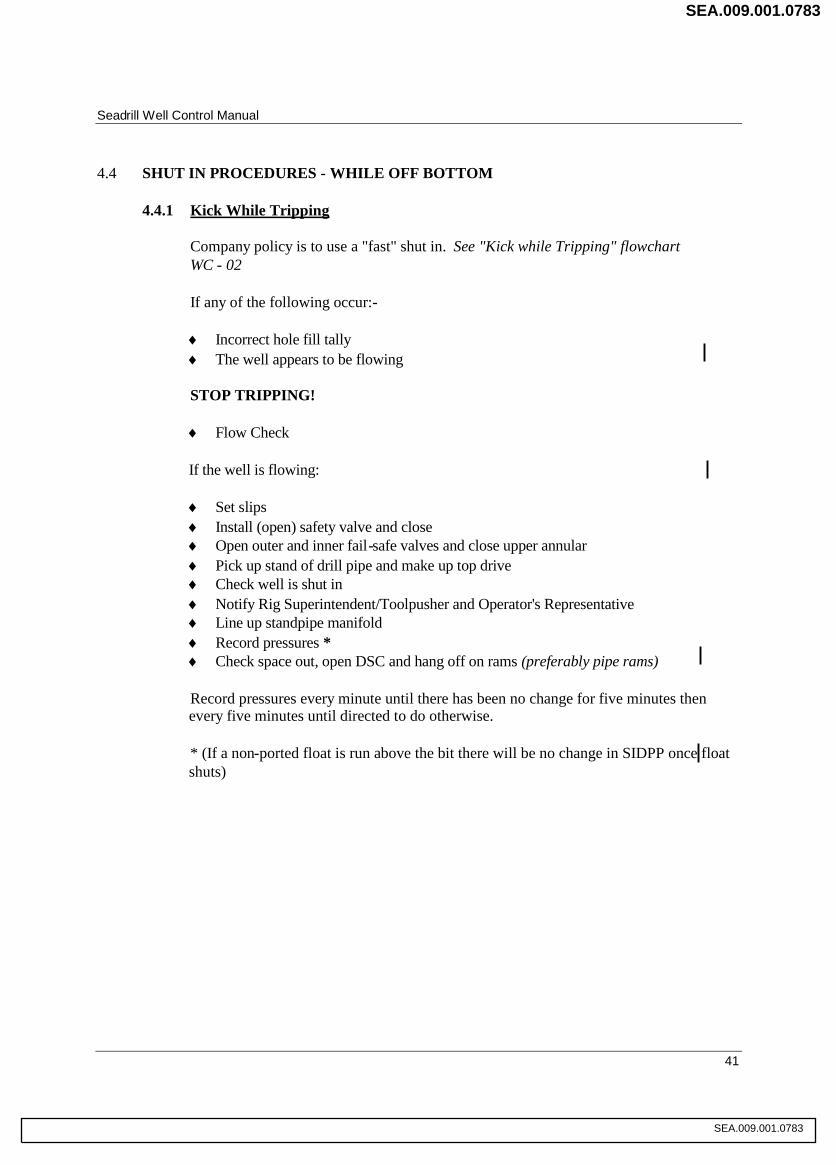
Seadrill Well Control Manual
41
4.4 SHUT IN PROCEDURES - WHILE OFF BOTTOM
4.4.1 Kick While Tripping
Company policy is to use a "fast" shut in. See "Kick while Tripping" flowchartWC - 02
If any of the following occur:-
Incorrect hole fill tally The well appears to be flowing
STOP TRIPPING!
Flow Check
If the well is flowing:
Set slips Install (open) safety valve and close Open outer and inner fail-safe valves and close upper annular Pick up stand of drill pipe and make up top drive Check well is shut in Notify Rig Superintendent/Toolpusher and Operator's Representative Line up standpipe manifold Record pressures * Check space out, open DSC and hang off on rams (preferably pipe rams)
Record pressures every minute until there has been no change for five minutes thenevery five minutes until directed to do otherwise.
* (If a non-ported float is run above the bit there will be no change in SIDPP once floatshuts)
SEA.009.001.0783
SEA.009.001.0783

Seadrill Well Control Manual
42
Flowchart: WC-02 Kick While Tripping
With Drillpipe in BOP and Top Drive in use
Instructions to the DrillerIt is the Driller’s responsibility to shut the well in quickly if it is flowing. He is authorised toflow check the well whenever he considers it necessary.
NOYES
If any of the following occur:-
1. Incorrect hole fill tally2. The well is flowing or any other
indication of well control problem
STOP TRIPPING
IS THE WELLFLOWING?
4. Set slips (Tie slip handles).5 Install open safety valve and close same.6. Open outer and inner choke line fail-safe valves
and close upper annular7 Pick up stand of drillpipe & make up Top drive8. Check well is shut in9. Notify Rig Superintendent/Toolpusher and
operators rep10. Line-up standpipe manifold11. Record pressure12. Check space out, open DSC and hang off rams on
(to be stipulated)
4. Notify Rig Superintendent/Toolpusher and Operator'Representative
5. Proceed as directed
3. Flow Check
SEA.009.001.0784
SEA.009.001.0784
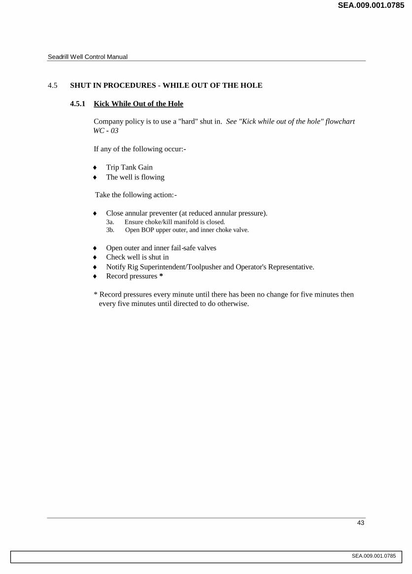
Seadrill Well Control Manual
43
4.5 SHUT IN PROCEDURES - WHILE OUT OF THE HOLE
4.5.1 Kick While Out of the Hole
Company policy is to use a "hard" shut in. See "Kick while out of the hole" flowchartWC - 03
If any of the following occur:-
Trip Tank Gain The well is flowing
Take the following action:-
Close annular preventer (at reduced annular pressure).3a. Ensure choke/kill manifold is closed.3b. Open BOP upper outer, and inner choke valve.
Open outer and inner fail-safe valves Check well is shut in Notify Rig Superintendent/Toolpusher and Operator's Representative. Record pressures *
* Record pressures every minute until there has been no change for five minutes thenevery five minutes until directed to do otherwise.
SEA.009.001.0785
SEA.009.001.0785
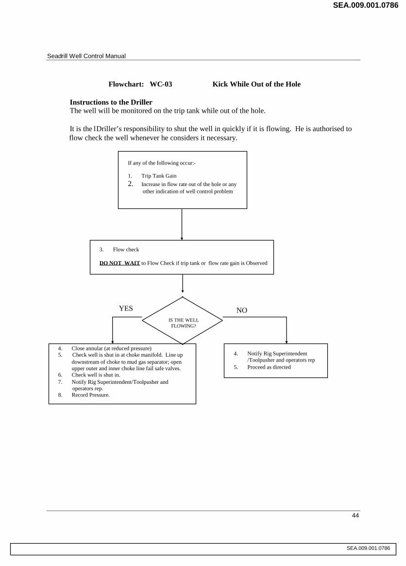
Seadrill Well Control Manual
44
Flowchart: WC-03 Kick While Out of the Hole
Instructions to the DrillerThe well will be monitored on the trip tank while out of the hole.
It is the lDriller’s responsibility to shut the well in quickly if it is flowing. He is authorised toflow check the well whenever he considers it necessary.
If any of the following occur:-
1. Trip Tank Gain2. Increase in flow rate out of the hole or any
other indication of well control problem
3. Flow check
DO NOT WAIT to Flow Check if trip tank or flow rate gain is Observed
IS THE WELLFLOWING?
4. Close annular (at reduced pressure)5. Check well is shut in at choke manifold. Line up
downstream of choke to mud gas separator; openupper outer and inner choke line fail safe valves.
6. Check well is shut in.7. Notify Rig Superintendent/Toolpusher and
operators rep.8. Record Pressure.
4. Notify Rig Superintendent/Toolpusher and operators rep
5. Proceed as directed
YES NO
SEA.009.001.0786
SEA.009.001.0786

Seadrill Well Control Manual
45
4.6 ACTIONS AFTER WELL IS SHUT IN
Once the Driller has shut the well in, checked to see that the BOP has functioned correctly, andinformed the Operator's Representative and the Rig Superintendent/Toolpusher on tour, whowill in turn inform the OIM, he is required to monitor the Shut In Drill Pipe Pressure and theShut In Casing Pressure and record his observations. Readings should be taken and recordedevery minute, until there has been no change for five minutes, and then every five minutes untilpressures can be considered "stable". Once pressures have stabilised it is still necessary to keepobserving and recording pressures, at interval to be specified by the RigSuperintendent/Toolpusher, as the records will give indications of gas migration or any otherchanges in the well conditions.
While the Driller is monitoring and recording pressures, the Rig Superintendent/Toolpusher isadvised to have the Subsea Engineer check over the BOP control system to make sure everythingis as it should be.
4.7 REPORTING WELL KICKS
As soon as reasonably practicable following a well kick, the “First Report of Well Kick” formin Section 4.7.1 is to be filled out and faxed to the local office. The local office will thenforward the report to Houston.
Telephone communication should be made through the normal chain of command, followingtransmission of the fax.
SEA.009.001.0787
SEA.009.001.0787

Seadrill Well Control Manual
46
4.7.1 First Report of Well Kick Form
FIRST REPORT OF WELL KICK
RIG NAME : DATE : TIME OF KICK :
OIM : CO REP’S NAME :
SIDP : psi SICP
PIT GAIN BEFORE CLOSING IN BOP : bbls TOTAL PIT GAIN
TRUE VERTICAL DEPTH : ft MEASURE DEPTH
BIT DEPTH : ft MWD DEPTH : ft DP FLOAT : YES NO
CASING SIZE : in BURST RATING : psi DEPTH :
LEAK-OFF TEST : psi MUD WEIGHT (BEFORE KICK) : ppg
KILL WT. MUD : ppg WEIGHT MATERIAL ONBOARD: sacks
ACTIVE SYSTEM VOLUME : bbls MUD PUMP #1 SPR psi SPM
MUD PUMP #2 SPR psi SPM
MUD PUMP #3 SPR psi SPM
BOP CONFIGURATIN (TOP DOWN)
Number of Annulars the BOP is equipped with (one/two) :
RAM #1 RAM #2 RAM #3 RAM #4 RAM #5
ANNULAR CLOSED #1 OR #2 : DP HUNG-OFF ON RAM # :
SIGNIFICANT EQUIPMENT PROBLEMS :
WELL PROBLEMS PRIOR TO KICK :
OPERATIONS PRIOR TO KICK :
WELL SHUT-IN BY : NAME: TITLE:
REMARKS
REPORT SUBMITTED FROM RIG BY NAME : TITLE :
REPORT RECEIVED BASED OFFICE BY NAME : TITLE :
SEA.009.001.0788
SEA.009.001.0788

Seadrill Well Control Manual
47
5.0 WELL CONTROL DECISION MAKING
5.1 RESPONSIBILITIES
5.1.1 Offshore Installation Manager (OIM)
The OIM has the final responsibility for well control. A Company OIM will be trainedin well control, but as he is not necessarily a drilling professional, he will consult withthe Rig Superintendent/Toolpusher, Operator's Representative and Rig Superintendent,to arrive at decisions on well control once a well control problem has occurred.
5.1.2 Rig Superintendent/Toolpusher
It is the Rig Superintendent/Toolpusher's responsibility, in consultation with theOperator's Representative, to advise the OIM on the well kill method that should beused. He has a duty to proceed with extreme caution and consider carefully all theimplications of his advice and actions in any well control situation.
5.1.3 Barge master
The Bargemaster will be involved in well control decision making to advise on expectedweather conditions, vessel motion, supply boat and helicopter logistics, and evacuationcapabilities. He will make every effort to be as accurate as possible in these predictions,communicating with local weather centres as required.
5.1.4 Driller and Drill Crew
The Driller and the Drill Crew will conduct the well killing operation under the RigSuperintendent/Toolpusher's supervision. The capability and experience of a crew mayhave some bearing on well control decision making, so all crew members have, as at anyother time, a responsibility to bring any concerns they may have about plannedoperations, equipment to be used or procedures to be followed, to the attention of theirimmediate supervisor, the Rig Superintendent/Toolpusher or OIM. All crew memberswho have a well control function, have a duty to alert their supervisor if they are in anyway uncertain of the part they are to play in any planned operation. It will be allsupervisors' responsibility to ensure that their crews understand what will be required ofthem in a well control operation.
5.1.5 Operator's Representative
The Operator's Representative, in consultation with the Rig Superintendent/ Toolpusherand his supervisors at the Operator's base, will advise the OIM on the well kill methodthat should be used. He has a duty to proceed with extreme caution and considercarefully the implications of his advice and actions in any well control situation.
SEA.009.001.0789
SEA.009.001.0789
Seadrill Well Control Manual
48
5.1.6 Third Party Employees
Third Party employees, such as the Mud Engineer and Mud Loggers, will be called onby the Operator's Representative, the Rig Superintendent/Toolpusher and the OIM toassist in well control decision making, according to their area of expertise. They have aresponsibility to bring any concerns they may have about planned operations, equipmentto be used or procedures to be followed to the attention of the Operator's Representative,the Rig Superintendent/Toolpusher or the OIM.
5.2 INTRODUCTION
This section of the manual is intended to provide guidelines to the decision making process in avariety of different situations in the event of a well control problem.
In reality, the specific conditions prevailing at the time that the problem occurs, will determinethe best course of action to take in order to resolve the problem.
This section should not necessarily be used as a guide at the moment that a problem occurs, butit is anticipated that general familiarity with the analysis presented in this section will enablepersonnel to be better prepared to deal with well control problems.
5.3 PIPE ON BOTTOM
If a kick is taken with the pipe on bottom, the well should be shut in as soon as is safelypossible.
Having established that the well is safely closed in, it will be necessary to decide on the mostappropriate method of killing the well. This decision is the responsibility of the OIM (See 5.1).
Having decided on the most appropriate course of action, the OIM is responsible for ensuringthat all involved personnel are made aware of the procedures that will be used to kill the well.This will be effected by Pre-kill Meetings, as set out in the installation's Well Control Plan.
These steps are applicable to any situation in which a kick is taken.
SEA.009.001.0790
SEA.009.001.0790

Seadrill Well Control Manual
49
Flowchart: WC-04 Preparation for Well Killing Operation
KICK TAKENWELL SHUT-IN
MONITOR THE WELLCONTINUOUSLY
INFORM BASE
PRE-KILL MEETING
Review well kill method.Review allocated responsibilities.Review contingency plans.
COMPLETE PREPARATIONS
Check EquipmentEnsure personnel are briefedVerify CommunicationsVerify CalculationsVerify Mud Weight
START UP KILL PROCEDURE
SEA.009.001.0791
SEA.009.001.0791

Seadrill Well Control Manual
50
5.4 PIPE OFF BOTTOM
5.4.1 Pipe off Bottom (Drillpipe Through BOP)
If an influx is taken during a trip, it will generally be necessary to return the drillstringto bottom before a constant bottomhole pressure method can be used to kill the well.
The surface pressure will be a major factor in determining the most suitable method ofreturning the pipe to bottom. It must be considered in relation to the string weight andthe pressure rating of the BOP's.
The first option that should be considered is stripping the pipe to bottom with the Rigequipment (See 5.5). Annular stripping is the most satisfactory method, however, ramcombination stripping may have to be considered if surface pressures are approachingthe pressure rating of the annular. On a floating Rig, ram combination stripping is aparticularly difficult operation.
The pressure limitations imposed by the Rig BOP system may dictate that stripping thepipe to bottom is impractical. In this case, some means of reducing the pressure enoughto allow stripping into the well must be implemented. (See Section 6 - Well KillTechniques).
5.4.2 Pipe off Bottom (Drill Collars Through BOP)
Every effort should be made to ensure that well control problems are avoided when theBHA is through the BOP Regaining control from a situation in which a well controlproblem has occurred with the BHA through the BOP can present serious complications.
If a kick has been swabbed in, it may be possible to bring the well under control bybleeding gas and lubricating mud into the well. It is, however, undesirable to leave thecollars in the stack for an extended period during a well control operation.
In any event, it is likely that the pipe will have to be stripped to bottom before the wellcan be killed.
There are considerable operational problems presented by attempting to strip a BHAthrough the annular preventer:-
The BOP element will be subject to considerable stress as the spiral collars arestripped through it.
Stabilisers in the BHA may prevent stripping completely.
SEA.009.001.0792
SEA.009.001.0792

Seadrill Well Control Manual
51
Further complications that may arise in this situation are numerous, but include thefollowing:-
There may not be sufficient weight of collars to strip through the annular BOP
Well pressures may force the collars out of the hole.
An internal blowout may occur through the drillstring.
The appropriate course of action required in these situations will depend to a largeextent on the particular conditions and equipment on the installation.
SEA.009.001.0793
SEA.009.001.0793

Seadrill Well Control Manual
52
Flowchart: WC-05 Off Bottom - Drill Pipe Through BOP
YES
NO
YES
NO
NO YES
YES
NO
IS ITPOSSIBLE TO
STAB IN A SAFETYVALVE?
WELL KICKSDRILL PIPE IN BOP
Hang off on lower ramsand shear pipe or droppipe and secure well.
SHUT WELL IN (WC-02)
SURFACEPRESSURE EXCEEDSAVAILABLE WEIGHT
FOR STRIPPING?
REDUCE PRESSURE BY:
1. Bull-heading2. Circulating (Driller’s method)3. Lubrication
Reduce annularclosing pressure
Attempt to lower pipethrough annular.
REDUCE PRESSURE BY:
1. Bull-heading2. Circulating (Driller’s method)3. Lubrication
REDUCE PRESSURE BY:
1. Bull-heading2. Circulating (Driller’s method)3. Lubrication.
CAN PIPE BELOWERED THROUGH
ANNULAR?
STRIP IN THE HOLE(WC-08)
CAN TOOLJOINTBE LOWERED THROUGH
ANNULAR?
SEA.009.001.0794
SEA.009.001.0794
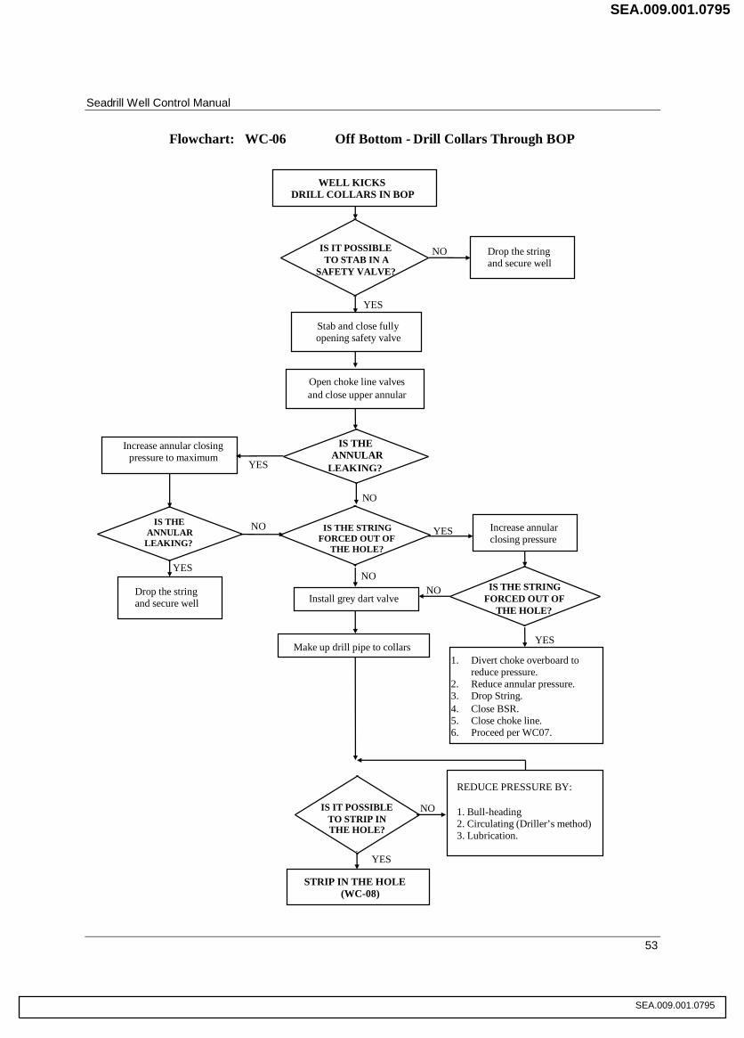
Seadrill Well Control Manual
53
YES
NO
YES
NO
YES
NO
YES
NO YES
NONO
Flowchart: WC-06 Off Bottom - Drill Collars Through BOP
IS IT POSSIBLETO STAB IN A
SAFETY VALVE?
WELL KICKSDRILL COLLARS IN BOP
Drop the stringand secure well
Stab and close fullyopening safety valve
IS THEANNULAR
LEAKING?
Increase annular closingpressure to maximum
Install grey dart valve
REDUCE PRESSURE BY:
1. Bull-heading2. Circulating (Driller’s method)3. Lubrication.
STRIP IN THE HOLE(WC-08)
YES
Open choke line valvesand close upper annular
IS THE STRINGFORCED OUT OF
THE HOLE?
IS THEANNULAR
LEAKING?
Drop the stringand secure well
Increase annularclosing pressure
IS THE STRINGFORCED OUT OF
THE HOLE?
Make up drill pipe to collars
IS IT POSSIBLETO STRIP INTHE HOLE?
1. Divert choke overboard toreduce pressure.
2. Reduce annular pressure.3. Drop String.4. Close BSR.5. Close choke line.6. Proceed per WC07.
SEA.009.001.0795
SEA.009.001.0795

Seadrill Well Control Manual
54
5.4.3 No Pipe in the Hole
Correct tripping procedures will ensure that an influx is detected before the pipeis completely out of the hole.
Should an influx remain undetected during tripping and the well is shut in with no pipe inthe hole, it may not be possible to re-introduce drillpipe into the hole in order to strip tobottom.
The limiting factor is the surface pressure in relation to the weight of the drillstring abovethe stack. A simple calculation will determine whether it will be possible to overcome thewellbore pressures with the weight of the string. The length of the riser limits the weightthat can be applied at the BOP
If the influx is immediately below the stack, it may be possible to either kill the well bylubricating mud into the well, or to reduce the surface pressures such that it becomespossible to re-introduce pipe into the well.
However, if the influx is some way down the hole, it may not be possible to reduce thesurface pressure significantly.
If the influx is migrating up the hole, it may be possible to kill the well by implementingthe Volumetric Control Method.
SEA.009.001.0796
SEA.009.001.0796

Seadrill Well Control Manual
55
Flowchart: WC-07 No Pipe In Hole
YES
NO
YES
NO
YES
NO
YES
NO
YES
NO
NO
IS IN FLUXDIRECTLY
BELOW RAMS?
WELL SHUT INNO PIPE IN HOLE
Monitor surface pressure
Bullhead kill weight mud and preparecontingency plan for fracture
IS ALL THE GASBLED FROM BELOW
THE RAMS?
Implement volumetriccontrol method
ATTEMPT TO REDUCESURFACE PRESSURE BY:
1. Bull-heading2. Lubrication
STRIP IN THE HOLE(WC-08)
YES
Lubricate mud into thehole and bleed off gas
IS THERE ANYPRESSURE UNDER
THE RAMS?
IS STRIPPINGPOSSIBLE?
Flow check andopen rams
IS STRIPPINGPOSSIBLE?
IS STRIPPINGPOSSIBLE?
SEA.009.001.0797
SEA.009.001.0797
Seadrill Well Control Manual
56
5.5 STRIPPING
The easiest method of stripping on a semi submersible installation, both from a proceduralstandpoint and in terms of wear on equipment, is annular preventer stripping, using the upperannular preventer.
Annular preventer stripping will be used to get the drillstring to bottom in the event that a kickhas been taken with the string out of the hole or off bottom.
A detailed, Rig specific, stripping plan will be developed from the following outline:-
1. Well has been shut in, with non-return valve (Gray Valve/HDIS Dart) installed as part ofshut in procedure.
2. Monitor surface pressures to decide if migration is occurring. Decide if string weight issufficient to strip in. If string weight will not overcome well bore pressure, the annularpressure must be reduced by bullheading or lubricating heavy mud into the wellbore.
3. Calculate pipe displacement and draw up Stripping Worksheet, (include predictions forpressure changes when string enters influx).
4. Decide on an overbalance margin to be maintained during stripping operations if influxmigrating allows this overbalance to develop. If no migration is occurring, developoverbalance, by restricting mud bled from the hole, once stripping commences.
5. Reduce annular preventer closing pressure and lower string through closed annularpreventer, reduce running speed as tooljoint passes through annular preventer.
6. Station a person close to the BOP control panel, with instructions to shut the well in with aset of pipe rams as a precaution against failure of the annular preventer sealing element orhydraulic closing system.
7. Follow stripping worksheet pressure schedule, (guidance available from Flowchart WC -08) and estimated pressure changes when string enters influx.
8. Keep trip tank lined up on riser to check on annular preventer element's sealing.
SEA.009.001.0798
SEA.009.001.0798

Seadrill Well Control Manual
57
YES
NO
YES
Flowchart: WC-08 Stripping
NO
Influx ismigrating
YES
NO
NO
NO
YES
ContinueStripping
WAS CORRECTVOLUME BLED
OFF?
Circulate out top of influxusing Driller’s Method
AT PRESSURELIMIT?
Bleed off mud to compensatefor migration
IS PIPE ONBOTTOM?
YES
IS INFLUXDIRECTLY BELOW
RAMS?
START STRIPPING IN
Bleed volume of mud equal tovolume of pipe stripped in
SURFACE PRESSUREINCREASES WITH
PIPE STILL IN?
Pressure increase aspipe is stripped in
Surface pressure dropsto value greater than
original
Pipe has enteredinflux
ContinueStripping
KILL THE WELL
SEA.009.001.0799
SEA.009.001.0799
Seadrill Well Control Manual
58
5.6 WHILE RUNNING CASING (OR LINER)
Before pulling out of the hole, prior to running casing, every effort will be made to ensure thatthe drilling fluid is conditioned and the well is under control in order to minimise the risk ofwell control problems while running casing.
Possible causes of well control problems while running casing include:-
A kick that was swabbed in on the last trip out of the hole
Swabbing in a kick on a connection while running the casing or working the casing throughtight spots
Swab/Surge pressures generated by vessel movement
Surge pressures while running casing too fast leading to losses and inducing an influx
When casing is run to cure a well control problem, such as after controlling an undergroundblow-out
Particular attention should be given to fluid monitoring when running casing to allow the aboveconditions to be detected as early as possible.
It is impractical to detail the procedure required in the event that a kick is taken while runningcasing or a liner. The immediate priority however, will be to close in the well, but the mostsuitable control technique can only be determined bearing in mind the particular conditions. Asit is always possible that there may be a requirement to shut an annular on casing, it is goodpractice (and therefore recommended), that the annular closing pressure be adjusted beforestarting to run casing to the pressure recommended for casing size, in the ManufacturersOperating Instructions.
Some of the available options can be summarised as follows:-
Cross over to drillpipe (unless current string weight is too great) and strip to bottom to kill thewell
Cross over to drillpipe, strip in until drillpipe is through the BOP and kill the well at currentshoe depth
Kill the well with the casing through the BOP
Drop the casing
Shear the casing
The major factors that will determine the course of action will include the following:-
SEA.009.001.0800
SEA.009.001.0800

Seadrill Well Control Manual
59
The possibility of collapsing the casing
The possibility of the casing being forced out of the hole by the well pressure
The feasibility of circulating out the kick by conventional means. (The small annularclearance may prevent circulation or cause excessive pressures)
The feasibility of killing the well by bullheading or volumetric methods.
5.7 UNDERGROUND BLOWOUT
5.7.1 Flow to a Zone Above a High Pressure Zone
The majority of underground blowouts have been as a result of a fracture to a weak zoneup the hole as a high-pressure zone is penetrated.
If an underground blowout is suspected, standard well control techniques should not beattempted to regain control of the well. If the annulus is opened, formation fluids willflow up the well bore to surface, thereby increasing surface pressures and possiblycausing further fracture.
A simple test will determine whether the well is a closed system. A small displacementpump should be lined up to the drillpipe and a small amount of fluid pumped. Ifdrillpipe and casing pressures increase, there is no indication of formation fracture. Ifthe drillpipe pressure does not increase, or if an increase is not evident in the casingpressure, then there is a possibility that the formation is fractured.
In order to halt an underground flow it will be necessary to pump fluid at a high ratedown the drillpipe and up the annulus. The fluid will eventually have to be at killweight in order to contain the pressure of the zone that is flowing but it will require aslow a viscosity as possible to ensure that it can be pumped at as high a rate as possiblewithout generating excessive circulating pressures.
Generally, the kill mud must flow at least as fast as the underground flow if it is not tobe dispersed as it comes out of the bit. The formation pressure of the zone that iskicking can only be estimated because a reliable SIDPP will not be available. The mudweight required to kill the well will depend on the position of the fracture in thewellbore and the average weight of the fluid occupying the annulus between the fractureand surface.
The fracture may only support a column of water, in which case it will be necessary tobalance the kick zone pressure with the sum of the hydrostatic pressure of the kill weightmud from the kick zone to the fracture, and the hydrostatic pressure of the water abovethe fracture.
SEA.009.001.0801
SEA.009.001.0801

Seadrill Well Control Manual
60
If the first attempt to control the flow is unsuccessful, the most likely causes will beeither that the volume or the velocity of kill mud was insufficient. Subsequent optionstherefore include increasing the volume of the kill mud pumped and pumping at agreater rate.
There remains the option of reducing the frictional resistance of the drillstring by suchmeasures as:-
Removing the nozzles of the bit with a charge run on wireline
Perforating the BHA close to the bit
Pumping a lighter, less viscous mud ahead of the kill weight mud in order to reducethe velocity of the inflow
SEA.009.001.0802
SEA.009.001.0802

Seadrill Well Control Manual
61
Flowchart: WC-09(i) Flow to a Zone Above a High Pressure Zone
NO
YES
Continued on WC-09(ii)
Leave annulus shut in ifpressure is not excessive
Run pressure test or logs toidentify/verify flow
UNDERGROUNDBLOW-OUT
CONFIRMED?
START STRIPPING IN
Monitor surface pressure No evidence ofunderground blowout
Suspect under ground blowoutbecause:
1. Drill pipe on vacuum2. Pressure has exceeded MAASP3. Annular pressure fluctuates
Implement standardwell kill techniques to
kill the well
Do not bleed fluid from annulus.Line up to pump mud to the annulus
Re-assess thesituation
If annulus pressure is building up pumpmud in the annulus. If annulus cannot
support mud pump waterLine up to pump mud to the annulus
SEA.009.001.0803
SEA.009.001.0803

Seadrill Well Control Manual
62
Flowchart: WC-09(ii) Flow to a Zone Above a High Pressure Zone
SECURE WELL OPTIONS:
1. Cement string in place2. POOH to plug loss zone3. POOH to run casing
YES
Continued from WC-09(i)
NO
YES
NO
NO
TRY
AGAIN
1. check mud at kill weight2. reduce viscosity3. reduce internal friction4. pump larger plug
OPTIONS:
1. Back off, strip up to casing,squeeze high fluid loss cementslurry to plug well
2. If circulation is possible onbottom, pump fresh water at max.rate to slough hole
DOES DRILLPIPEAND ANNULUS PRESSURE
INDICATE THATUNDERGROUND FLOW
HAS CEASED?
MIX BARITE PLUGPREPARE 2 TIMES ANNULUS VOLUME OF KILL
WT ( MIN. PV & YP BARITE PLUG RECIPE )
NO
TRYAGAIN
1. check mud at kill weight2. reduce viscosity3. reduce internal friction4. pump larger plug
MIX LCM PILLPrepare 2 times annulus volume of kill mud/Barite plug
Disp. LCM Pill down annulus to top of loss zone
Pump kill mud/barite plug down string at maximum rateSqueeze LCM Pill down annulus to top of loss zoneKeep pumping unless surface pressure limits reached
DOES DRILLPIPEAND ANNULUS PRESSURE
INDICATE THATUNDERGROUND FLOW
HAS CEASED?
IS THE PIPESTUCK?
OPTIONS:
1. Install dart (if sub in string),squeeze high fluid losscement slurry to plug well
2. Pump fresh water atmaximum rate to try andslough hole
SEA.009.001.0804
SEA.009.001.0804

Seadrill Well Control Manual
63
Flowchart: WC-10 Flow to a Zone Below a High Pressure Zone
SECURE WELL
NO
NO
YES
RE-ASSESS THESITUATION
SHUT IN WELL
Drilling ahead and experience losses
STOP
Indications of underground blowoutNo surface pressureannulus and drillpipe on vacuumPossible annulus pressure build up
CURE LOSSES ANDDRILL AHEAD
YESIS IT POSSIBLE TOCURE LOSSES?
Pressure test formation (sec.5.7.1)
CANNOT CONTROL LOSSESWell starts to flow
Do not bleed fluid from annulusLine up to pump mud or water down annulus
YES
NOUGBOCONFIRMED?
SURFACE PRESSUREINDICATES NO FLOW?
SEA.009.001.0805
SEA.009.001.0805

Seadrill Well Control Manual
64
5.7.1 Flow to a Zone Above a High Pressure Zone (Continued)
If these measures do not bring the well under control, there remains the option to mix anLCM pill or barite plug (See Section 6.8), and displace it down the annulus and into thefracture as the kill weight mud is pumped down the drillpipe. The pump rates on thedrillpipe and the annulus should be such as to ensure that the LCM pill or barite plug iscompletely displaced into the fracture over the period of time that will be required topump the prepared volume of kill weight mud.
Past experience has shown that in many cases, having halted the underground flow, afurther flow has been initiated by attempts to pull off bottom. If the decision is made topull off bottom having halted an underground flow, extreme care should be taken.
5.7.2 Flow to a Zone Below a High Pressure Zone
The most likely cause of an underground blowout that flows down the wellbore from ahigh-pressure zone is that a naturally fractured or cavernous formation is drilled into.The resultant losses reduce the hydrostatic head of the drilling fluid to such an extentthat a permeable zone higher up the wellbore begins to flow.
When the well is shut in, it is unlikely that any pressure will be recorded on either thedrillpipe or the casing gauges. However, the casing pressure may increase if gasmigrates up the casing/drillpipe annulus; pumping mud down the annulus prevents thisrise in pressure.
Having established that the flow is downwards to a loss zone, there is a suggestedoption that should be considered for halting the flow:-
Control losses with LCM until all of the loss zone is exposed to the wellbore andsqueeze cement in to the zone.
SEA.009.001.0806
SEA.009.001.0806

Seadrill Well Control Manual
65
6.0 WELL KILL TECHNIQUES
6.1 RESPONSIBILITIES
6.1.1 Offshore Installation Manager (OIM)
The OIM has the responsibility of ensuring that those he appoints to positions with awell control function are competent to fulfil that function, have received the trainingrequired by Government regulation and the Company's training matrix, and have beenmade aware, through instruction and exercise, of the actions required of them.
During well killing, as at all times, the OIM has the responsibility of ensuring thatoperations are planned and executed with the highest regard for the safety of personnel,the installation and the environment.
6.1.2 Rig Superintendent/Toolpusher
It is the Rig Superintendent/Toolpusher's duty to keep the OIM informed and advised ofmatters, such as well control problems, which might affect the safety of personnel or theinstallation.
It is the Rig Superintendent/Toolpusher's responsibility to ensure that he and thosewhom he supervises, i.e., Drillers and Drill Crews, are competent to deal with wellcontrol problems when they occur and have received the required training and exerciseto become confident in recognising and dealing with well control problems.
It is the Rig Superintendent/Toolpusher's responsibility, in consultation with theOperator's Representative, to advise the OIM on the well kill method that should beused. Unless there is no possible way it can be accomplished, a "constant bottom holepressure" method of well killing will be used.
Once the well kill planning is complete it will be the Rig Superintendent/Toolpusher'sresponsibility to execute the plan with all due regard to safety of personnel, theinstallation and the environment.
6.1.3 Bargemaster
The Bargemaster has responsibility for the marine operations, logistics and weatherforecasting. These will be of vital importance during well kill operations whencomplications, due to bad weather or lack of materials, are to be avoided if at allpossible.
The Bargemaster will be involved in all phases of well control planning and decisionmaking.
SEA.009.001.0807
SEA.009.001.0807
Seadrill Well Control Manual
66
6.1.4 Driller and Drill crew
The Driller is responsible for recognising well control problems and taking immediate,safe action to contain, and thus minimise, the ingress of any formation fluid into a wellbore.
It is the Driller's responsibility to ensure that he and his crew are familiar with the Rig'swell control plan and understand the actions that will be required of them.
It is the Driller's responsibility to check that safety valves and all equipment required formonitoring and recording drilling fluid volumes, flowrates, pump speed and casing, anddrill pipe pressures is in a serviceable condition and ready for immediate use.
6.1.5 Operator's Representative
The Operator's Representative is responsible to the OIM for providing specialist wellcontrol advice with, if available, detailed knowledge of the specific area of operation.
Prior to spudding in, it is the Operator's Representative's responsibility to cooperate withthe Rig Superintendent/Toolpusher and the OIM in developing a well control plan. If awell control problem does arise it will be the Operator's Representative's responsibilityto cooperate with the OIM and Rig Superintendent/Toolpusher in deciding on thespecific well control methods to be used to overcome the problem.
6.1.6 Third Party Employees
Those Third Party Employees with well control functions may, if required, be calledupon to assist in the development, or implementation, of the well control plan.
6.2 GENERAL
6.2.1 Constant Bottomhole Pressure
In the Company's well control operations, the goal is to maintain a "constant bottomholepressure", slightly in excess of formation pressure while circulating the kick out atconstant pump rate, namely, the kill rate.
SEA.009.001.0808
SEA.009.001.0808

Seadrill Well Control Manual
67
6.2.2 Calculations
Well control calculations and the preparation of kill sheets, step down charts, graphsand pressure schedules will not be discussed at any length in this manual. It isanticipated that users of this manual will have a minimum well control qualification toIWCF or WellCap and be competent to make the necessary calculations.
6.3 THE WAIT AND WEIGHT METHOD
6.3.1 Description
The "wait and weight" method is so named because the crew first shuts the well in andwaits for kill-weight mud to be mixed. Then new, weighted-up mud is pumped into thehole while old mud and kick fluids are removed through the choke. Pumping in newmud while removing old mud and kick fluids results in lower surface or casing pressurethan first circulating the kick out with old mud, and then circulating in new mud.Surface pressure is lower with one circulation because when new mud has filled thedrillstring and begins to flow into the annulus, it adds its higher hydrostatic pressure tothe back pressure held on the well by the choke. Since the heavy mud adds tobottomhole pressure, the choke must be opened more to maintain the bottomholepressure constant. The added hydrostatic pressure results in a lower casing pressurerequired to control the expansion of formation gas in the annulus. Lower casingpressure reduces the chances of formation breakdown at the casing shoe.
The Company's procedure is to use the "wait and weight" method when the kickrequires kill mud.
Two important characteristics of the "wait and weight" method should be noted. One isthat circulating pressure decreases as new kill-weight mud is circulated down thedrillstring. The pump rate must be kept constant. The other is that surface casingpressure cannot be held constant to keep bottomhole pressure constant as new mud fillsthe drillstring; SICP must be allowed to increase. To understand why circulatingpressure/SIDPP decreases as new mud is pumped down the drillstring, it must be kept inmind that:-
Circulating pressure shows pump pressure when the well is being circulated
SIDPP also indicates the amount that formation pressure exceeds the hydrostaticpressure of the old mud in the drillstring
Thus, after the new mud weight is calculated from SIDPP and new mud is circulateddown the drillpipe, the new mud weight offsets the pressure exerted by the formation onthe mud in the pipe and drillpipe pressure decreases to the final circulating pressure(FCP).
SEA.009.001.0809
SEA.009.001.0809

Seadrill Well Control Manual
68
6.3.2 Pump Start Up
Pump start-up procedures can be critical due to choke line friction (CLF), which placespressure on the well that is not shown on the casing pressure gauge. This pressure canbe substantial and cannot be neglected, particularly in deeper waters. Procedures tomeasure CLF are mentioned in Section 1.4.4
6.3.3 Procedure
Company procedure for the "wait and weight" method is:-
1. When the kick occurs, shut the well in and record pressures.
2. Fill out the worksheet and increase the mud weight.
3. When the new mud is ready, open the choke and slowly bring the pump up to killrate. (With subsea BOP’s, let the casing pressure drop by the amount of thechoke-line friction pressure.) When the pump is up to the kill rate, observe thedrillpipe gauge and hold initial circulating pressure constant by adjusting the choketo the calculated ICP.
4. While keeping the pump rate constant, continue pumping new mud down the pipe.Circulating pressure will decrease as new mud slugs the pipe. The value forcirculating pressure can be checked on the kill-sheet graph or step-down chart, andthe choke opened or closed to bring circulating pressure to the correct value.
5. When the new-weight mud arrives at the bit, maintain FCP and keep the pumpstrokes constant until new mud reaches the surface.
6. Stop the pump, close the well in, and check for pressure.
6.4 THE DRILLER'S METHOD
6.4.1 Description
The Driller's method is the most basic of all methods and can be employed in a numberof well control situations. The Driller's method has some limitations. For example,casing pressure rises to a maximum value with this method. Since the well is circulatedwith original weight mud, all of the additional pressure needed to prevent furtherintrusions of kick fluids into the well must be maintained by holding back-pressure withthe choke. No heavier kill-weight mud is used at this stage of the "Driller's method. Ifgas is in the kick fluid, it will expand as it is circulated up the hole because of reducedpressure near the surface. Also, the choke size must be reduced when gas reaches thechoke to maintain bottomhole pressure. This is a critical point in controlling thedrillpipe pressure; if it drops too low, more formation fluid will enter the wellbore and ifit becomes too high, the formation will fracture and lost circulation could lead tobroaching or an underground blowout.
SEA.009.001.0810
SEA.009.001.0810

Seadrill Well Control Manual
69
The Driller's method requires a relatively long time to kill the well; at least twocirculations - one to circulate the influx out, and one to circulate kill mud into and up thehole. Since pressure on the BOP stack is maintained during the two circulations, thepossibility of other troubles occurring increases. Moreover, the Driller's method haslimited use on Rigs with subsea BOP stacks because pressure losses through the chokeline cause back-pressure which must be added to the already high casing pressure (ifimproperly managed) that could occur with the method. Where a subsea stack is in use,the chance of formation breakdown and lost returns can be high. In spite of itslimitations, however, the Driller's method is acceptable when the danger of lost returnsis minimal. Also, circulation can begin immediately, thus lessening the chance of thedrillstring getting stuck.
To sum up, the Driller's method is not recommended when:-
Lost returns are likely Only surface casing is set Long strings of casing have badly worn spots
In short, the Driller's method is best used when little or no danger of lost circulationexists, when Rig equipment or material shortages do not permit using the "wait andweight" method or when a kick has been swabbed in and there is no requirement toincrease mud weight.
6.4.2 Pump Start Up
Pump start-up procedures can be critical due to choke line friction (CLF) which placespressure on the well that is not shown on the casing pressure gauge. This pressure canbe substantial and cannot be neglected, particularly in deeper waters. Procedures tomeasure CLF are mentioned in Section 1.4.4
6.4.3 Procedure
Company's procedure for the Driller's method of well control is:-
1. When the kick occurs, shut-in the well in and record pressures.
2. Complete kill sheet.
3. To start circulating - open the choke. Allow the casing pressure to reduce by anamount of pressure equal to choke line friction.
4. When the pump is at kill-rate speed, observe the drillpipe gauge and hold initialcirculating pressure constant by adjusting the choke. Maintain a constant pumprate. Do not allow the pump to change speed.
5. Circulate the influx out, holding ICP constant at the original value until the kick iscirculated out of the hole. When all of the influx has been pumped out, the well isagain shut in. Both SIDPP and SICP will reach the original SIDPP noted when the
SEA.009.001.0811
SEA.009.001.0811

Seadrill Well Control Manual
70
kick occurred if the kick is caused by abnormal pressure (or read 0 for a "swabbedin" or "improper hole fill" caused kick).
6. Stop the pump, close the choke, and mix kill-weight mud.
7. When kill weight mud is ready, start circulating - See Step 3.
8. Hold casing pressure constant until kill mud reaches bit (final circulating pressure isreached).
9. Choke operator monitors standpipe pressure and manipulates choke to maintainfinal circulating pressure.
6.5 VOLUMETRIC METHOD
6.5.1 Description
The volumetric method is used for controlling bottomhole pressure when no drillpipecommunication exists or when the well cannot be circulated. It can also be used whenthe well is closed in and the crew is waiting on orders or equipment. Further, it can beused when stripping in or out of the hole.
The technique is not a well-killing method in the sense of being a method of circulating,since it simply coordinates the increase or decrease of annular pressure with the amountof mud displaced from the hole. The basis of the volumetric method is that each barrelof mud contributes a certain hydrostatic pressure to the bottom of the hole, which maybe measured as pounds per square inch, per barrel (psi/bbl). In other words, if 1 bbl offluid is bled off, then bottomhole pressure is reduced by the amount of pressure exertedby that 1 bbl. If 1bbl of fluid is pumped in, then the pressure exerted by that 1bblincreases bottomhole pressure. To obtain a value for psi/bbl, the mud gradient in psi/ftis divided by the annular capacity in bbl/ft, or the hole capacity in bbl/ft if no pipe is inthe hole. The formula is:-
MW .052 Annular Capacity (at top of well) = psi/bbl.
The value for psi/bbl must be coordinated with pit volume or fill-up tank volume so thatthe number of barrels may be read directly.
To use the method, the well is closed in, pressure stabilised and the SICP is recorded. Ifthe SICP does not rise, the bottomhole pressure remains constant. If SICP rises, mudcan be bled from the well according to the calculated psi/bbl value in order to maintainconstant bottomhole pressure. Since bottomhole pressure is the sum of casing pressureand pressure exerted by the mud column, the volumetric method of bleeding off excesscasing pressure by adding mud hydrostatic pressure works.
In summary, the volumetric method may be used when:-
SEA.009.001.0812
SEA.009.001.0812

Seadrill Well Control Manual
71
1. No pipe is in the hole.
2. The bit is a long distance off bottom.
3. The bit or the drillstring is plugged.
4. Stripping in or out of the hole.
5. Not enough weighting material is available on the location
6. Awaiting the arrival of perforating equipment.
6.5.2 Procedure
When a well is shut-in under pressure, a step-by-step procedure for the volumetricmethod is:-
1. Record SICP.
2. Line up the choke line to a manual choke so that fluid can be discharged into anaccurately graduated tank, such as the trip tank or stripping tank.
3. Calculate the psi/bbl of fluid bled from or added to the well.
4. Monitor SICP and allow it to increase 100psi; this increase occurs as the gas bubblemigrates up the hole. This will be used as a safety margin.
5. Allow SICP to rise by the amount equal to the pressure reductions to be made insteps on the well.
6. Bleed metered volume of mud from the well while holding the SICP constant.
7. Repeat as necessary.
6.6 BULLHEADING
Bullheading into a well is forcing gas back into a formation by pumping into the annulus fromthe surface. The well remains closed in so that mud and kick fluids are displaced into theweakest exposed formation. Bullheading is not a routine procedure, but it can mean thedifference between a lost well and one that is under control and returned to normal operations.
Bullheading may be used when:-
Anticipated surface pressures are expected to exceed the pressure limitations of the surfaceequipment.
SEA.009.001.0813
SEA.009.001.0813

Seadrill Well Control Manual
72
When kick fluids, such as H2S, are hazardous if circulated to the surface.
When the drillpipe is plugged or parted so that kill mud cannot be circulated to bottom.
When a weak zone below the kick takes mud too fast for the well to be killed.
When bullheading with water based mud, pump rate must be fast enough to exceed the rate atwhich the gas migrates up the hole. One indication of too low a pumping rate is an increase,rather than a decrease, in pump pressure. Ideally, bullheading will fracture a formation andcontinued pump pressure will force gas back into the formation. Anytime high pressure isapplied at the surface; a formation breakdown is possible at the casing shoe rather than at apoint lower in the hole. Should fracture at the shoe occur, an underground blowout maydevelop and broaching around the casing is a possibility. Therefore, bullheading is not withoutrisk and caution should be exercised whenever the principle is employed.
6.7 BARITE/CEMENT PLUGS
A barite plug is a slurry of barite and fresh water mixed to a density of about 21 ppg. Aphosphate thinner, such as sodium acid pyrophosphate (SAPP), is usually added to the freshwater at a concentration of about 0.7lb/bbl of water. After the acidic phosphate thinner isadded, the pH of the fresh water should be increased to about 9.0 by the addition of caustic.Approximately 0.25lb of caustic per barrel of water should be required. The phosphate thinnerpromotes rapid settling of the barite as soon as slurry agitation is stopped. When settled, bariteforms an almost impermeable seal in the wellbore. Since a barite plug requires vigorousagitation (to prevent settling of the barite), the mixing and pumping equipment normally usedfor cement slurries should be used to place the plug. Often, the first attempt to seal the well ismade using a slug volume designed for a plug of settled barite, a few hundred feet in length.
The smaller barite plugs are often placed in a manner similar to a balanced cement plug. Theslurry is under-displaced to prevent contamination of the annular plug, and the pipe is thenpulled quickly above the plug. The heavy plug should fall free as the pipe is pulled. The well isthen circulated above the plug for several hours.
When conditions are more severe, a small barite plug may not result in a successful seal. Largebarite plugs involving the use of several thousand sacks of barite are sometimes used when veryhigh sub-surface well flow rates are involved. When using a large plug, no attempt is made towithdraw the drillpipe, and the drillpipe is allowed to become stuck. The drillpipe isover-displaced to prevent the barite from settling in the drillpipe so that if the plug fails, anotherattempt can be made.
If the barite plug is successful, a small cement plug designed to seal off the inside of the lowerportion of the drillstring follows it. The drillstring is backed off above the zone where it isstuck, and the well is circulated for several hours.
The use of barite slurries for sealing high-pressure zones in well control operations hasdeveloped over the past decades as an alternative to the use of cement slurries. Cement slurriesstill have a place in well control, but it is often the case that an effective seal can not beaccomplished using cement when the sub-surface flow is primarily gas. Gas tends to channel
SEA.009.001.0814
SEA.009.001.0814
Seadrill Well Control Manual
73
through the cement plug before it sets. Generally, better results are obtained with therapid-settling barite slurries.
6.8 COMPLICATIONS DURING WELL CONTROL OPERATIONS
6.8.1 Introduction
Current well control teaching, deals primarily with relatively uncomplicated situationsin which kicks are taken during drilling with the drillstring at or near bottom with noadditional problems or complications being encountered during the well controloperation. Unfortunately, when some kicks are being handled, complications developwhich may force departure from standard and practiced well control procedures. Whileit is not possible to anticipate all problems that can occur, a Well Control ProceduresManual would not be complete without covering some of the more commoncomplications that have occurred in the past.
It should be noted that each situation will have its own circumstances and the emphasisof planning and decision making must be on considering ALL possibilities, and havingevery effort directed towards "NOT MAKING A BAD SITUATION WORSE".
6.8.2 Gas Migration
After a kick is detected and the well is shut in, the well pressures initially increase inresponse to formation flow. As the fluids trapped in the well are compressed and thewell pressures rise, this flow gradually decreases and finally stops.
In some cases, problems may develop which prevent the initiation of kick circulation forlong periods of time. In other cases, problems may develop during kick circulation,which require that the well be shut in again with kick fluids still in the well. If the kickfluid is gas and the well remains shut-in for a long period of time, the gaseous formationfluid trapped in the annulus may migrate a significant distance towards the surface.
Gas rising in a shut-in well will cause a gradual increase in pressure at all points in thewell. This pressure increase occurs because the gas cannot expand if the well remainsclosed. If the gas is not allowed to expand as it travels up the hole, it retains the samepressure and exerts this pressure in all directions. This means increases in pressure atthe surface, at bottom, and at all depths in the hole, which will eventually causeformation fracture or equipment failure. In order to avoid this unacceptably largeincrease in well pressure, the gas should be allowed to expand under controlledconditions to keep the bottomhole pressure constant at a value slightly above theformation pressure.
Controlled expansion gas rising in a shut-in well is best accomplished using thehand-adjustable choke. After the SIDPP has stabilised, note the drillpipe and casingpressures. Allow the SIDPP to rise about 100psi to provide a safety margin for chokeoperations. Then, wait and permit the SIDPP to further elevate by the amount ofpressure you wish to reduce on the SIDPP (50psi is usually a good figure).
SEA.009.001.0815
SEA.009.001.0815
Seadrill Well Control Manual
74
Pressure on the SIDPP now will have:-
1. Stabilised
2. Risen to provide a safety margin of ± 100psi
3. Further risen by the amount of pressure that the SIDPP is to be reduced as fluid isremoved through the choke
Now, the Choke Operator cracks the choke open and bleeds off a defined quantity ofdrilling fluid (¼ or ½bbl). He closes the choke and waits for the choke lag time to pass.He repeats the procedure as necessary to achieve the selected "SIDPP + safety margin
value”.
Well pressure will be maintained above formation pressure and further flow offormation fluid into the wellbore will be prevented. This method of bleeding off aspecified small volume of fluid and then waiting for pressures to stabilise should alwaysbe used because of the lag time involved between choke manipulation and thecorresponding response in drillpipe pressure.
After all of the gas has migrated to the top of the well, casing pressure will become andremain static. The well should then remain shut in until well circulation is possible.Although gas is at the surface, well circulation can be initiated in the conventionalmanner, i.e., by holding the casing pressure constant while bringing the pump up tospeed. Very little initial choke adjustment will be required while starting the pumpbecause of the large volume of compressible, low-viscosity gas at the surface.
Just before the gas reaches the surface, the casing pressure will tend to increase rapidly,requiring more frequent intervals of bleeding mud through the choke. It may be difficultto initiate well circulation properly during this period. Under these conditions, it isrecommended that all of the gas is allowed to migrate and pressures allowed to stabilisebefore initiating circulation.
This procedure will maintain the bottomhole pressure slightly above formation pressureand prevent further influx of formation fluid into the well. Although the casing pressurewill tend to increase over the initial shut-in casing pressure, much lower casingpressures will result than if no mud were released. The chance of formation breakdownor equipment failure will be greatly reduced.
6.8.3 Surface Equipment Problems
Perhaps the most frequent complications experienced during well control operations arerelated to problems with the surface well control equipment. The more common surfaceequipment problems include:-
1. Plugged choke.2. Erosion of choke or choke manifold.3. Pump problems.
SEA.009.001.0816
SEA.009.001.0816
Seadrill Well Control Manual
75
4. Leak in sealing elements of the BOP stack.
Usually, these problems are not serious if they are diagnosed quickly and corrected.Surface equipment problems not evident from leaks or power failures are generallydetected by a departure of the drillpipe pressure and/or casing pressure from normalbehavior. As soon as a problem with the surface equipment is suspected, the pumpshould be stopped immediately and the well closed in. The pump operator should alwaysremain at his station and be ready to stop the pump immediately if so instructed by thechoke operator.
6.8.3.1 Plugged Choke
Formation fragments carried by the drilling fluid will sometimes lodge in thechoke, creating a plug. This situation will be apparent from a rapid rise in boththe drillpipe pressure and casing pressure. When this situation exists, it is veryimportant to stop the pump immediately. The choke can be fully opened, for aninstant, in an attempt to dislodge the plug (if possible this should be donewithout allowing drillpipe pressure to fall below schedule).
If this fails, surface flow should be re-routed to another choke. Any trappedpressure should be released by periodically bleeding a small volume of muduntil the shut-in drillpipe pressure returns to approximately the proper shut-invalue. The well control operations can then be resumed.
6.8.3.2 Erosion of Choke or Choke Manifold
Abrasive solids, such as sand carried by the drilling fluid, can cause erosion inthe high pressure piping system. A cut-out choke can result in simultaneousdecrease in drillpipe pressure and casing pressure that cannot be corrected bychoke manipulation.
After stopping the pump and closing the choke, it will probably also benecessary to close a valve in the choke manifold to stop the flow completely.Well control operations can normally be resumed after re-routing the surfaceflow to another choke.
If fluid erosion results in a leak in the choke manifold system at a location thatcannot be conveniently bypassed, the well can remain shut in until the problemcan be corrected. However, the shut-in well should be continually monitoredfor pressure increases due to upward gas migration.
6.8.3.4 Pump Problems
In the event of pump failure, the well should be shut in until another pump canbe brought on line. Since the slow circulating rate pressure of the second pumpmay be different, it may be necessary to use a different circulating drillpipepressure. The new drillpipe pressure can be determined by bringing the pumpup to speed while adjusting the choke to hold the casing pressure constant.
SEA.009.001.0817
SEA.009.001.0817

Seadrill Well Control Manual
76
After the new pump is running at the desired kill speed, the new circulatingdrillpipe pressure should be equal to the observed drillpipe pressure reading atthat time. The slow circulating rate pressure for that pump speed is thedifference between the observed circulating drillpipe pressure just after pumpstart-up and the shut-in drillpipe pressure.
If kill mud has not yet reached the bit, a new drillpipe pressure schedule shouldbe drawn up, based on the new value for reduced pump pressure.
In some cases the pump may not fail completely, but may change significantlyin displacement efficiency because of a bad piston, valve, or some otherproblem. This problem can usually be detected by erratic drillpipe pressurebehavior or by gradually decaying drillpipe pressure. If the problem goesundetected, the choke operator will tend to compensate by closing the choke inorder to increase the drillpipe pressure back to the desired value.
6.8.3.5 Leak in Sealing Elements of the BOP Stack
Occasionally, as casing pressures increase during the circulation of the kick, aleak may develop across the annular preventer, at a ram, or at a connection inthe BOP stack. After stopping the pump, pressure at the leak can usually bebled off by closing one of the lower rams below the leak. Subsea BOP stacksshould, if possible, is monitored during well control operations with subsea TVor ROV equipment.
6.8.4 Sub-Surface Problems
In addition to problems with the surface well control equipment, mechanical problemswith the sub-surface well circulation can and occasionally do occur during the wellcontrol operations. Some of the more common sub-surface well problems discussed inthis section include:-
1. Plugged bit.2. Bit nozzle washout.3. Hole in the drillstring.4. Borehole fracture, cement failure, or casing failure.
Sub-surface well problems generally must be detected and diagnosed from the behaviorof drillpipe and casing pressure, and from records of pit volume changes. As in the caseof surface equipment failures, the first step taken when well problems are detected is tostop the pump immediately and shut-in the well.
6.8.4.1 Plugged Bit
Debris that enters the drillstring during a kick or is circulated down thedrillstring will result occasionally in a plugged bit. In some cases, only partialplugging results, while, in others, well circulation is completely stopped. Bit
SEA.009.001.0818
SEA.009.001.0818
Seadrill Well Control Manual
77
plugging can be detected at the surface by a sudden increase in the circulationdrillpipe pressure without a corresponding increase in casing pressure.
If only partial plugging is present, it may be possible to continue kickcirculation at a higher drillpipe pressure or a lower circulation rate. The pumpcan be brought up to speed while simultaneously holding the casing pressureconstant at the shut-in value in order to determine the new reduced circulatingpressure. The new pump pressure can be determined as the difference betweenthe observed drillpipe pressure just after start-up and the shut-in drillpipepressure.
If heavy mud has not yet reached the bit, a new drillpipe pressure scheduleshould be computed based on the new value for reduced pump pressure. Thechoke operator should also remain alert for a sudden decrease in drillpipepressure, which indicates that the plug may be breaking free. The chokeoperator can verify the current pump pressure at any time by stopping the wellcontrol operation and then restarting the pump at constant casing pressure.
If a partially plugged bit or drillstring is not correctly diagnosed, the chokeoperator will tend to open the choke in order to get the drillpipe pressure backon schedule. This will result in a decrease in the casing pressure andbottomhole pressure, allowing the influx of formation fluid into the well toresume. Should this condition continue unnoticed for a long period of time, avery large influx may be taken.
A completely plugged drillstring may have to be perforated so that wellcirculation can be resumed. The hole should be placed as close as possible tothe bottom of the drillstring to insure that most of the kick fluids are above thehole. Otherwise, it may not be possible to maintain the bottomhole pressureconstant using conventional well control procedures. The new reducedcirculating pressure which results after perforating the drillstring should beestablished as discussed previously by maintaining a constant casing pressureduring pump start-up.
6.8.4.2 Bit Nozzle Washout
A bit nozzle washout results in a sudden decrease in drillpipe pressure withouta corresponding decrease in casing pressure. As in the case of a partiallyplugged bit, the well control operation can be continued after the new value forthe reduced circulating pressure is established.
6.8.4.3 Hole in the Drillstring
In a few instances, well control operations have been complicated by thedevelopment of a washed-out hole in the drillstring. This can be detected at thesurface by a rapid decrease in drillpipe pressure without a correspondingdecrease in casing pressure. The location of the hole with respect to the kickfluids can sometimes be estimated from the drillpipe pressure after shut-in.
SEA.009.001.0819
SEA.009.001.0819
Seadrill Well Control Manual
78
If the drillpipe pressure is much higher than the expected shut-in drillpipepressure and does not respond to bleeding a small volume of mud, a hole abovethe kick zone is indicated.
If no kill mud is in the drillpipe, the drillpipe pressure may be the same as theshut-in casing pressure.
If the hole is below the kick zone, the drillpipe pressure will return to near theexpected shut-in value. In this case, it will not be possible to distinguish a holein the drillpipe from a washed-out bit nozzle. However, both of these situationsshould be handled in the same manner.
When a hole is above the kick zone, it is no longer possible to maintain thebottomhole pressure constant while circulating the kick in the conventionalmanner.
If upward gas migration is evident and there is a hole in the drillstring, it is notpossible to maintain a constant bottomhole pressure by bleeding mud whileobserving the drillpipe pressure. The upward gas migration can be handledusing the same procedure as when the drillstring is off bottom or completelyout of the hole. This procedure is the volumetric method. In some cases, itmay be practical to wait until the kick zone migrates up past the hole in thedrillpipe.
6.8.4.4 Borehole Fracture, Cement Failure or Casing Failure
The selection of proper casing setting depths is often critical to the success of awell. In some cases, when a large kick is taken with a long interval of openborehole just prior to the next scheduled casing setting depth, it may not bepossible to circulate the kick to the surface without exceeding the fracturepressure of the weakest exposed formation. Once formation fracture occurs,the resulting loss of annular pressure usually allows additional influx of fluidsfrom the high pressure zones into the wellbore. This can lead to an undergroundblowout situation in which formation fluids flow uncontrolled from the deeperhigh pressure zone to the more shallow, fractured formation.
The pressurising of shallow formations can lead to dangerous problems forsubsequent wells in the area and should be stopped as soon as possible.
Underground blowout situations can also result from failure of the intermediatecasing or a cement failure near the bottom of the casing string.
A failure in the sub-surface wellbore, cement, or casing, which causes anuncontrolled loss of well fluids from the sub-surface annulus, can be detectedfrom an unexpected drop in surface pit volume, casing pressure, and drillpipepressure. If the fluid level in the annulus begins falling, mud should be pumped
SEA.009.001.0820
SEA.009.001.0820

Seadrill Well Control Manual
79
into the annulus to maintain the well full and keep the surface pressures fromlater building up due to the loss of mud.
Control or isolation of the zone of lost circulation from the high pressure zonethat is kicking is critical. One effective means to accomplish this is through theuse of a barite plug to seal the lower portion of the well. For a description ofthe possible uses of a barite plug, refer to Section 6.8.
SEA.009.001.0821
SEA.009.001.0821

Seadrill Well Control Manual
80
6.8.5 Emergency Disconnect from a Pressured Well
In an emergency, a floating Rig depends on the ability to move off location leaving thewell shut-in. Rig specific move off plans, an essential part of the installation's WellControl Plan, will be devised by the OIM with the assistance of the Bargemaster and theRig Superintendent/Toolpusher. Some examples follow to illustrate possible plans ofaction prior to moving the Rig off location:-
(i) With a dart sub installed in the BHA
1. With pipe hung off on pipe rams below the shear rams, install and pumpdown a back-pressure or dart valve until seated in the dart sub. Keep casingpressure constant while circulating.
2. After the dart seats, bleed off drillpipe pressure and observe the drillpipepressure gauge to determine if the dart is holding pressure. (If dart is notholding see Section 6.8.5(ii) ).
3. If the dart is holding pressure, and with the drillstring hung off on the upperrams, close the lower pipe rams.
4. Displace mud in the riser with sea water.
5. Close the fail-safe valves; close the shear/blind ram preventer to shear thepipe.
6. Pull out of the hole with the sheared drillpipe.
7. Disconnect the lower marine riser package; confirm disconnect; slack offthe guide-line tensioners.
8. Move the Rig off location.
(ii) With no dart sub or leaking dart.
1. With pipe hung off on pipe rams sufficiently below the shear rams to clearthe tool joints, close the shear rams and shear the pipe.
2. Close the choke and kill valves on all outlets below the shear rams.
3. Displace mud in the riser with sea water. Use the choke/kill lines, ifavailable, above the shear rams; or subsea booster line, if available; or pumpdown the sheared drillpipe (sheared drillpipe may allow little or nocirculation).
4. Pull the sheared drillpipe out of the hole.
SEA.009.001.0822
SEA.009.001.0822
Seadrill Well Control Manual
81
5. Disconnect the lower marine riser package; confirm disconnect; slack offthe guide-line tensioners.
6. Move the Rig off location.
6.9 WELL CONTROL IN HORIZONTAL WELLS
Well control in horizontal wells will have to be addressed on a case by case basis. Obviously,the principals of pressure calculations and the difference between "measured depth" and "truevertical depth" are the same as in any directional well, but the potentially large influx volumespossible in an extended reach horizontal section make the necessity for avoiding an influxparticularly keen. Precautionary measures against swabbing such as pumping out of thehorizontal section are to be used whenever possible.
Continuing research and inquiry on the subject of well control in horizontal wells will lead tothis section of this manual being updated as information becomes available.
SEA.009.001.0823
SEA.009.001.0823
Seadrill Well Control Manual
82
7.0 OIL BASED MUD
7.1 INTRODUCTION
The reaction of formation gas with oil based drilling fluids can be quite different from thereaction with water based drilling fluids. Hydrocarbon gas and base oil have many morechemical similarities than hydrocarbon gas and water. When hydrocarbon gas and base oilcome into contact in a drilling fluid, the gas needs little persuasion to join up with the base oilin the drilling fluid. This joining or dissolving of the gas into the oil, is called "going intosolution". The result of this solution is much like the solution of carbon dioxide (CO2, a gas)dissolved into a soft drink (liquid). An understanding of the behavior and consequences of thisgas/oil solution during well control situations is necessary when using oil base muds.
A major effect of this joining of gas and base oil under the right conditions is that the gas canbe hidden with very little to show that it is there, just like the CO2 in an unopened soft drink.The right conditions for gas being in solution with base oil are the conditions that usually existdownhole in a well. Depending upon these conditions, when 1 bbl volume of gas plus 1 bblvolume of mud join, the result does not equal 2bbls of a gas/mud mixture. There is a reductionin volume when the gas and base oil in the mud join to form a solution. The amount of volumereduction depends upon the make up of the gas, the make up of the mud, the pressure andtemperature under which they come in contact, and how they are mixed. This reduction ofvolume (when combined with the fact that the gas in solution is not free to expand as it movesup the annulus) makes it very difficult to catch this type of kick during a flow check. It mayrequire 5 to 10 minutes with the pumps off while metering returns to the trip tank to benoticeable.
Another effect is the sudden expansion of the gas as it comes out of solution. The primarycause for this is a reduction of pressure just like opening the soft drink. One (1) bbl of gas fromthe formation will expand the same amount in its trip from downhole to the surface regardlessof whether water based or oil based fluid is used. The difference (due to the solubility of thegas and oil) is where that expansion takes place. Gas that is "free" in a water based fluid willexpand proportionally to the reduction in pressure as it moves up the annulus. Any free gaswith an oil based fluid would do the same; however, any gas dissolved in the oil will notexpand until it is free of the solution, or "bubbles out". The point where the gas comes out ofthe mixture or "bubble point" also depends upon the make up, pressure and temperature of themixture. With the right conditions, the gas that was dissolved into the mud downhole may notbegin to break free until it reaches the surface and gets a little help such as running over theshale shakers (just as you can free the CO2 in the soft drink by shaking it). More commonly, thegas will come out of solution and begin expanding within the top several hundred feet of thewell. You may not know that the gas is there until it unloads your well or riser. An oil basemud can carry enough drilled gas in solution to have the same effect. A gas kick must bedetected early to minimise well control problems.
One more effect of the gas dissolving into the base oil of a drilling fluid is that the altereddrilling fluid may have different physical properties after the gas is dissolved in the base oil. Adrop in viscosity or gel strength would let the solids settle out of the mud and may cause thepipe to stick. Due to this, it is recommended that the mixture is not allowed to sit any longer
SEA.009.001.0824
SEA.009.001.0824

Seadrill Well Control Manual
83
than necessary for proper control of the well. This is a situation where the "Driller's" methodand concurrent method of circulating out a kick are often considered.
7.2 EFFECTS OF SATURATION
The types of fluids, how they are mixed, and the mixture's pressure and temperature at anysingle point in time will determine how much gas can be dissolved into or absorbed by theliquid at that point in time. When the liquid is holding as much gas as it can under thoseconditions, it is said to be at the "point of saturation" or "saturated". If the liquid is below thepoint of saturation, it will absorb any more gas it comes into contact with until it reaches thepoint of saturation. If the liquid is at the point of saturation, any gas it comes into contact withremains as a "free" gas and will not be absorbed.
For the conditions that concern us, the point where the base oil in the mud is able to absorb thegreatest amount of gas is found at the temperatures and pressures downhole at the bit. Thepoint where the mud has the most difficulty holding the gas in solution is at the surface. Wewill look at three different cases and their effect on gas expansion/surface pressures whenformation gas mixes with oil based mud at total depth:-
7.2.1 Case I. Unsaturated Mixture
If conditions are such that a gas kick is taken and shut-in without enough influx tosaturate the mud with gas, there will be a loss in volume of the gas influx due to the gasgoing into solution with the mud. There will be no free gas to migrate and expand suchthat SICP will remain constant. At this point, the kick will act like a salt water kick. Donot assume that it is. While circulating this kick out, a point will be reached where themixture is at saturation due to the lower pressure caused by a reduction in hydrostatichead. If circulation is stopped at this point, the kick/mud mixture will remain liquid. Ifpressure is reduced by bleeding off the choke or resuming circulation, the gas will beginto bubble out of the mud. The more the pressure is reduced, the more free gas willbubble out of the mud. As this mixture is circulated further up the hole, increasingamounts of back pressure on the choke will be required to make up for the loss ofhydrostatic head from the ever increasing amounts of expanding gas. If you were tobullhead this kick/mud mixture back down the hole, the increasing pressure would forcethe free gas back into solution until all free gas is dissolved back into the liquid at thesaturation point. The point in the hole where the gas begins to break free will dependupon the type of fluids in the mixture, the sum of the hydrostatic head and chokepressure, the temperature and the original saturation level of the kick/mud mixture. Itmay start separating right off bottom, which will induce "gas expansion pressures" onthe formation. It may take place up in the casing, in the choke line, or even downstreamof the choke and could expose the Rig to more gas than it has the capability of handling.The longer that the gas is held in solution, the less time it will have to distribute itself
through the mud column and the higher the gas concentrations will be upon reaching thesurface. High, sudden, and totally unexpected casing pressures can be obtained with thistype of kick.
SEA.009.001.0825
SEA.009.001.0825

Seadrill Well Control Manual
84
7.2.2 Case II. Saturated Mixture
If conditions produce a kick/mud mixture at saturation point, conditions will be asdescribed above except that free gas will start coming out of the mixture as soon ascirculation is started.
7.2.3 Case III. Over-saturated Mixture
When conditions are right and a larger amount of gas influx is taken than that needed tosaturate the mud, gas that did not dissolve into the mud will be present as free gas. Thiswill have the same surface indication as a gas kick with a water based mud. It is not.The kick is larger than the surface readings indicated because a portion of the gas influxis hidden in the mud. The hidden portion will remain hidden until the bubble point ofthe dissolved gas is reached. Only the free gas will be expanding as it moves up the hole.When this expansion is evident, it is an indication that a very difficult procedure will be
necessary to kill the well.
7.3 COMPRESSIBILITY
Oil is slightly more compressible than water. This means that it will change volume more thanwater with a change in pressure (expanding as pressure is reduced and contracting as pressure isincreased). Although this change in volume is very small and will not be noticed during normalcirculation, it does have some effect. A small expansion of the oil based mud will show up inthe slightly longer time it takes flow to stop after shutting off the pumps when compared towater based mud. The reverse of this is that due to mud contraction, it will take longer forpressures to stabilise. It will also take longer for pressures to stabilise when a kick is taken in ahigh pressure, low permeability zone where slow pressure rises are mistaken for gas migration.If pressures are not given enough time to stabilise, too low a kill weight mud will be used. Theincreased compressibility will also require more time for pressure stabilisation after chokeadjustments than with a water based mud.
7.4 SUMMARY
Any gas kick may cause problems in well control due to problems with gas expansion. Theseproblems can be magnified by the ability of an oil based mud to hide a gas kick due to gasgoing into solution at downhole conditions. The worst case situation should be looked at.Assume that it is a gas kick. Can the well and surface equipment handle the possible pressuresdue to gas expansion? Can the Rig's equipment handle the possible concentrations of gas at thesurface, even at the slowest possible circulation rates? Should the kick be bullheaded back intothe formation? Should it be plugged off instead of circulated out?
Oil based mud can carry enough drilled gas in solution under conditions to unload the topportion of the hole or marine riser when lower pressure and temperature conditions are reachednear the surface. Always keep the diverter packer installed. Be ready to fill the hole from thetop to make up for any hydrostatic head lost from the mud being blown out of the hole. Whencirculating out a kick, be prepared for unexpected gas breaking out at any time, evendownstream of the choke.
SEA.009.001.0826
SEA.009.001.0826

Seadrill Well Control Manual
85
The solubility of gas in an oil based mud can hide a gas kick sufficiently to keep it from beingnoticed during a flow check or when making a connection. More time is required and returnsmay have to be taken at the trip tank to be noticed. Do not let your guard down during the"normal" long time it may take for a flow check due to expansion of the mud.
A gas/oil solution will not support the solids that the oil alone will. Expect solids to fall out ofthe mud and possibly stick the pipe and/or pack off the hole. Consider using the "Driller’s"method or concurrent circulation method.
As with any gas kick, early detection/shut-in and circulation will minimise problems. Expectmore and more sudden gas expansion than with a water based mud due to the increasingamounts of gas in the annulus as it comes out of solution. Be ready to safely vent large amountsof gas at the surface. Exercise due caution throughout the circulation but especially in handlingthe gas through the surface equipment.
SEA.009.001.0827
SEA.009.001.0827

Seadrill Well Control Manual
86
8.0 JACKUP WELL CONTROL PROCEDURES
8.1 OBJECTIVE
To ensure that the operations covering the well control procedures undertaken on a Jackup afterthe BOP has been installed are carried out in a safe and efficient manner according to an agreedprocedure to minimize risk to personnel, equipment and the environment.
Scope
This procedure applies to well control situations on all SeaDrill Jackups with the BOP installed
Background
Unless otherwise specified, blowout prevention systems shall follow the American PetroleumInstitution recommended practices, API RP 53. Blowout and well control practices shallcomply with the laws of the jurisdiction within which the facility is located.
The Offshore Installation Manager (OIM) shall ensure that the members of the crew arecognizant of the laws and recommended practices for the locale. The OIM shall verify theminimum training required by law for each SeaDrill assigned to his facility.
General Requirements
1. Prior to spudding a new well, the OIM shall be informed about the history of pressuresencountered at the well location. The OIM and his Drillers shall share this information,especially the depths and geological sections that might have abnormal pressures. Thisinformation is available in the Operational Plan for the well, which is supplied by theoperator. The OIM will meet with the Company Representative to agree on the steps,personnel, and stations involved in handling the killing of a kick or the diverting of ablowout. They will also agree on how to rid the stack of any trapped gas before openingthe stack after a well kick.
2. Prior to commencing of the procedure and before each tour in a shallow gas suspectedarea, hold a toolbox meeting with all personnel involved in the operation. Reviewrelevant Job Safety Analyses (JSAs) and modify procedures if necessary.
3. Obtain relevant information from the Operator and agree to a specific step by step wellcontrol procedure. Post the written procedure and a Pre-kick Data Sheet (Kill sheet) atthe Driller's console.
4. Slow Circulating Rates (SCR) will be taken and recorded prior to drilling out, at leastonce each tour while drilling, after changing the BHA, after changing the mud weight,and after every 500 feet drilled.
SEA.009.001.0828
SEA.009.001.0828

SeaDrill Well Control Manual
87
5. Flow checks shall be made on drilling breaks, flow rate increases, pit gains, decreases inpump pressure with an increase in pump strokes, and any time the Driller suspects thatthe well may be flowing.
6. Blowout preventer (BOP) control lines and valves must be clearly identified.
7. All valves, manifold piping, fittings, and connections in the BOP system must be able towithstand any pressure for which BOP is rated
8. The hydraulic lines from the accumulator to the BOP stack shall be inspected frequentlyto determine if they are in good condition, free of leaks, and remain connected
9. Drilling will not continue if the amount of barite on the rig drops below the number ofsacks needed to raise the density of the mud in the system by one pound per gallon, orbelow the number of sacks agreed upon with the Operator prior to commencing drilling.
10. The BOP and choke and kill manifold shall always be lined up and ready for a wellcontrol situation.
11. The choke and kill lines shall be pumped through daily at a minimum.
12. Ensure that choke and kill lines are fully open before opening rams or annular afterkilling a well
13. The duties for each crewman during a BOP or diverter drill shall be conspicuouslyposted on the rig floor and in other necessary work areas
14. Pit drills and trip drills must be conducted daily and recorded in IADC report.
15. All pre-recorded information requirements must be available at all times at the Driller'sconsole.
Safety Precautions
Extra care and is required to ensure the safety of new or inexperienced personnel.
Personnel must stay clear of the BOP when under pressure
Rig personnel must stay clear from the rotary table opening while the BOP is functioned
During a well kill, personnel must stand clear of high pressure lines at all times. Extracare must be taken during manual choke operations to minimize exposure to highpressure lines. All non-essential personnel must be excluded from the area.
When opening the BOP stack, gas may be trapped in the stack above the choke lines butbelow the upper most preventer. If the preventer is opened quickly, gas may rush outcausing mud, shale, or sand cuttings to be blown out of the hole. The bushings may beblown out of the rotary table. Gas shall be bled off or flushed from the preventers as perSeaDrill well control procedures.
Safety equipment must be tested and ready for use at all times.
SEA.009.001.0829
SEA.009.001.0829

WELL CONTROL MANUAL
88
Well Control While Drilling
The decision tree "Jackup Well Control Procedures - Drilling – FORM A" outlines theprocedures to be used in the event that a kick is taken while drilling. These procedures areintended to be general in order to cover all Jackups, but they must be tailored to fit eachindividual rig's specific requirements.
Well Control While Tripping
The decision tree "Jackup Well Control Procedures - Tripping – FORM B" outlines theprocedures to be used in the event that a kick is taken while tripping. These procedures areintended to be general in order to cover all jackups, but they must be tailored to fit eachindividual rig's specific requirements.
Responsibilities
Area Manager: Approves well control procedures which differ from SeaDrill procedures.
OIM: Responsible for the overall safety of the rig and the strict adherence to procedures.Ensures that the crews are properly trained and drills are performed regularly.
Rig Superintendent/Toolpusher: Ensures that the BOP equipment is properly maintained andused.
Driller: First line of defense to shut the well in; monitors the hole for early signs of flow; mustbe familiar with SeaDrill and Operator's Procedures and policies.
Operator: Provides information, instructions and safety procedures and precautions forOperator's supplied materials and services.
References
MODU Operation ManualOperator Well Control Procedures Manual
Note: It is recognized that each mobile offshore drilling unit (MODU) is different from otherswith respect to equipment specifications and designed layout. The intent of this system is toprovide the basics for each procedure, with special emphasis on the safety and environmentalaspects of the tasks to be performed. It is the obligation of each MODU to use these genericprocedures as a guide to complete a Job Safety Analysis (JSA) that will become that MODU'srig-specific procedure.
SEA.009.001.0830
SEA.009.001.0830

WELL CONTROL MANUAL
89
JACKUP WELL CONTROL PROCEDURES – DRILLING (FORM A)
Is the WellNo Flowing? Yes
ResumeOperation as
Directed
Immediatelynotify Rig
1. Close annular, open choke valves to monitorpressure.
Superintendent,Toolpusher and 2. Record time, pit gain, SIDP, and SICP
OperatorReDresentative 3. Verify / ensure well is shut-in
IF
Well Kill Per Procedure
Wait & Weight method preferred;Driller's method if not preparedfor Wait & Weight.
(Prior to circulating down string,may require cross-circulatingchoke & kill lines to break gel)
Kill BOP Stack per Procedure
Proceed Per Instructions
SEA.009.001.0831
SEA.009.001.0831

WELL CONTROL MANUAL
90
JACKUP WELL CONTROL PROCEDURES – TRIPPING (FORM B)Preferred Procedure: Hard Shut-In
Kick Recognition: If any of the following occurs -
1. Well flows with pump off (pipe stationary)2. Improper hole fill (less than calculated) when POOH3. Improper displacement (more that calculated) when TIHNote: For Items 1 and 2, take into consideration possible effects ofadded slug.
11 F
At First Indication of Kick:Immediately notifyRig Superintendent, 1. Stop tripping operations, position tool joint at
Toolpusher andOperator's
rotary table, install fully opened safety valve, closesafety valve
Representative 2. After checking for flow, install Gray inside BOP ordart sub as planned
3. Open safety valve
I F
No - Is Well Flowing?(Check Trip Tank) Yes
I r
No I Has influx occurred?(Verify Kick)
11 F
Yes
I r
Return bit back tobottom whilemonitoring trip tankto check for well flow -- Yes
II F initiation. Has well
Resume flow initiated?Operation(s)as Directed
--No
I FI F
SEA.009.001.0832
SEA.009.001.0832

WELL CONTROL MANUAL
91
IF
IFIF
Shut-In Well
1. Close upper annular,open choke valves. 1. Close annular, open choke valves
2. Record time, pit gain,SIDP, and SICP
2. Record time, pit gain, SIDP, and SICP
3. Verffy / ensure well isshut4n3. Verffy /ensure well
is shut4n IF
I . Align down hole returns to trip /stripping tank
2. Strip back to bottom per procedure,monitor returns on trip / stripping
tank
IF
Note:
May requirecross-
Kill Well Per Procedure
First circulation use Driller'scirculating chokeandkill linesbefore
- - - - -
taking returnsupchokeline.
Should it be determined thatinsufficientmud weight is in the hole, weight upaccordingly.
I F
Kill BOPStackPerProcedure
I F
ProceedPerInstructions
SEA.009.001.0833
SEA.009.001.0833

WELL CONTROL MANUAL
92
SHALLOW GAS PROCEDURES - JACKUP
Objective
To properly plan for the possibility of a shallow gas event in order to protect personnel, equipment andthe environment.
Background
Encountering shallow gas can be a serious problem when spudding the well before the BOP has beenset, when only a short casing string has been set, or when drilling an open-hole section prior to setting along protective string. Gas can quickly reach the surface with little warning because the hole isshallow. When the BOP stack is in place, the failure of a weak casing string or weak formations mayallow shallow gas to broach to the sea floor. Semisubmersibles are capable of rapidly moving offlocation, but Jackups do not have that option If the BOP or riser is not in place, the only possibility tocontrol the flow is to fill the annulus with kill mud.
Pre-Planning
Ensure that there is complete agreement with the Operator's Representative on how a shallow gas kickwill be handled if it is encountered.
The "Driller's Instructions for Shallow Gas Well Control" shall be posted on the drill floor prior tocommencing operations on the well. The decision to shut the well in will be based on the results of theOperators Well Plan. The Driller has the ultimate responsibility to decide if shutting the well in is safeunder the given conditions.
Handling a shallow gas kick requires immediate action to prevent the situation from getting out ofhand. It is important that all personnel involved become familiar with the contents of this procedure.The OIM/Rig Superintendent and the Operator's Representative should brief the crews on their role onhow to handle a shallow gas situation prior to spudding the well.
If the well starts to flow, the Driller shall immediately shut in or divert the well as approved in theOperators Well Plan. The OIM, Rig Superintendent and the Operators Representative shall be notifiedimmediately of the situation.
Safety Precautions
Extra care is required to ensure the safety of new personnel.
If the rig is equipped with a diverter system, the diverter packer must always be in place and lockeddown when drill pipe is in the hole.
Safety equipment must be tested and ready for use.
Ensure that the diverter has been completely tested and that the knife valves operate properly to lineup the diverter line in either direction prior to spudding the well.
SEA.009.001.0834
SEA.009.001.0834

WELL CONTROL MANUAL
93
Record (each watch) the direction of wind and current and the time and direction of any changesthat occur.
SeaDrill recommends that at least one reserve pit shall contain kill weight mud.
The OIM and Company Representative must remain aware of the wind and current direction andthe location of any boats around the rig while spudding the well or drilling the surface hole.
Shallow Gas Procedures with Diverter Installed on Drive Pipe
If shallow gas is encountered, the Driller will immediately close the diverter and notify theOIM/Rig Superintendent/Toolpusher and the Operator's Representative of the situation. On theiradvice will line up and pump kill weight mud at the fastest rate that pressure will allow, using allavailable mud pumps.
If drilling mud from the active and reserve systems is exhausted before the well is killed, seawaterwill be pumped while building mud volume and weight.
If the OIM determines that the rig or personnel could be in danger from the shallow gas situation,he will make the decision concerning whether to initiate evacuation or abandonment of the rig.
Shallow Gas Procedures with Conductor Pipe Set
In some situations while drilling this section of the well, it is possible for the well to start flowing withoutentering an abnormally pressured shallow gas zone. This is most likely to occur due to swabbing duringa trip, gas cut mud while drilling, or flow after cementing. In this situation, if the flow is detected soonenough and the conductor pipe is set at sufficient depth, it is possible to shut the well in andsuccessfully kill it using conventional well control methods.
If shallow gas is encountered, the Driller will immediately close the well in or divert as per the"Driller's Well Control Response with Diverter Installed" and notify the OIM/RigSuperintendent/Toolpusher and the Operator's Representative of the situation.
Well killing procedures will be initiated as per the well control plan.
If the OIM determines that the rig or personnel could be in danger from the shallow gas situation,he will make the decision concerning whether to initiate evacuation or abandonment of the rig.
SEA.009.001.0835
SEA.009.001.0835
WELL CONTROL MANUAL
94
Responsibilities
Operations Manager: Approves well control procedures which differ from SeaDrill procedures.
OIM: Responsible for the overall safety of the rig and its personnel.
Rig Superintendent/Tool Pusher: Ensures that the crews are properly trained and drills are performedregularly. Ensures that the BOP equipment is properly maintained and used.
Barge Supervisor: Ensures that lifeboats and liferafts are maintained in good working condition foruse in abandonment operations when necessary.
Driller: Monitors the hole for early signs of shallow gas. Must be familiar with SeaDrill and Operator'sProcedures and policies.
Operator: Provides information, instructions and safety procedures and precautions for Operator'ssupplied materials and services.
References
SeaDrill Emergency Evacuation Plan
SeaDrill Safety Management System
SeaDrill Rig Operation Manual
Operator's Site SpecificEmergency Plan
Operator's Well Control Procedures Manual
Operator's Well Plan
Note:. It is recognized that each mobile offshore drilling unit (MODU) is different from others withrespect to equipment specifications and designed layout. The intent of this system is to provide thebasics for each procedure, with special emphasis on the safety aspects of the tasks to be performed. Itis the obligation of each MODU to use these generic procedures as a guide to complete a Job SafetyAnalysis (JSA) that will become that MODU's rig-specific procedure.
SEA.009.001.0836
SEA.009.001.0836

WELL CONTROL MANUAL
95
SEADRILL JACKUPS WORKING WITH DIVERTERSSEADRILL / Operator Surface Hole Bridging DocumentHazard Identification and Prevention
If Yes, how much pressure?
No. Question Response Guidance
I
Does the Company man know youhave the capability to close the wellin and circulate with your divertersystem?
If No, educate the Company Man on rig specificdiverter capabilities.
Drive pipe only set
Does the Operator plan ondiverting if the well flows?2
If Yes, OK. If the Operator plans to close in thewell with only the drive pipe set, a MOC isrequired.
Drive pipe and 2nd string of casing (conductor) set and cemented (cement not cured)
3Does the Operator plan to holdpressure on the cement whilecuring?
4
If the well flows while Waiting onCement, does the Operator agree toclosing in the well and monitoringpressure?
If Yes, OK. If No, MOC is required.
Does the Operator plan to wash outthe casing annulus with tubingacross the diverter sealing element?
5
If Yes, MOC required, complete with plan tomaintain sufficient hydrostatic pressure and a wayto quickly remove the wash-out tubing in the eventthe well begins to flow.
Conductor pipe set and drilling surface hole
Does the Operator agree to drillthis hole section with a minimummud weight of 9.5 ppg?
If Yes, OK. If no, MOC required. A discussionmust take place with appropriate shorebased
6 management to determine why the requestedminimum mud weight can not be used. (i.e. depletedformations)
If the well flows a small amount(less than 50% on flo sho)with thepumps off, does the Operator agreeto close in the well?
7
If Yes, close in and check pressures. If belowMaximum allowable casing pressure, kill well usingconstant bottom hole method. If pressure is greaterthan MACP, divert well and prepare to evacuate rig.IF No, MOC is required.
8
If the well flows a large amount(greater than 50% on flo-sho) withpumps off, does the Operator agreeto divert?
If Yes, Ok. If No, MOC required.
SEA.009.001.0837
SEA.009.001.0837

WELL CONTROL MANUAL
96
If Yes, how much pressure?
No. Question Response GuidanceConductor pipe set - Tripping
Does the Operator plan to pumpout of the hole to preventswabbing?
9
If Yes, OK. If No, pull first 5 stands with trip tankpump off, continuously observing mud level in bellnipple. Fill each stand and record same.Toolpusher required on rig floor.
10 If well starts to flow slowly, doesoperator agree to close well in? If Yes, OK. IF No, MOC required.
Surface casing (3rd string) set and cemented (cement not cured)
I IDoes the Operator plan to holdpressure on the cement whilecuring?
12
If the well flows while Waiting onCement, does the Operator agree toclosing in the well and monitoringpressure?
If Yes, OK. If No. MOC is required.
Does the Operator plan to wash outthe casing annulus with tubingacross the diverter sealing element?
13
If Yes, MOC required complete with plan tomaintain sufficient hydrostatic pressure and a wayto quickly remove the wash out tubing in the eventthe well begins to flow.
SEA.009.001.0838
SEA.009.001.0838

WELL CONTROL MANUAL
97
SEADRILL DIVERTING PROCEDURES - DRILLING
1 Detect kick. Driller
2 Place diverter control system in divert position. This willclose the diverter bag and open both vent lines.
Driller
3 Position tool joint near floor and out of Diverter. Driller
4 Close up-wind valve. Driller
6 Notify Derrickman to switch to kill weight mud (ifavailable) and then saltwater as needed.
Lead Tong Hand
7 Notify rig mechanic to shut down all ignition sources andprepare to shut down non-essential power.
Toolpusher / OIM
8 Driller continues to pump with mud pumps at full speedor as required to bring well under control.
Driller
9Toolpusher and safety officer assemble all non-essential personnel at up-wind lifeboat station. Toolpusher / SO
10 Operator's representative notifies shore base and standbyboat of possible evacuation.
Operator's Rep.
I I Evacuate drill floor and shaker area. Toolpusher / Driller
12 Monitor rig condition for possible evacuation. Post bubblewatch around rig.
Toolpusher / Driller
13 Evacuate non-essential personnel by safest meanspossible 0IM
14Evacuate rig as required. All power will be shut down ifrig is evacuated. The decision to evacuate will be madeby the 01M.
0IM
ACTION TO BE TAKEN PERSON RESPONSIBLE
Notify OIM/Rig Supt. and Operator's representative that
5 well is kicking.A decision to evacuate drill floor will be made at this Backup Tong Hand
time.
SEA.009.001.0839
SEA.009.001.0839
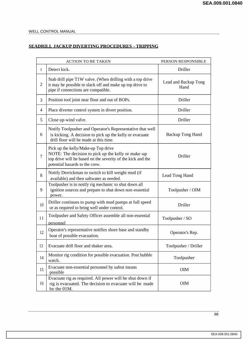
WELL CONTROL MANUAL
98
SEADRILL JACKUP DIVERTING PROCEDURES - TRIPPING
3 Position tool joint near floor and out of BOPs. Driller
4 Place diverter control system in divert position. Driller
5 Close up-wind valve. Driller
6Notify Toolpusher and Operator's Representative that wellis kicking. A decision to pick up the kelly or evacuatedrill floor will be made at this time.
Backup Tong Hand
8 Notify Derrickman to switch to kill weight mud (ifavailable) and then saltwater as needed.
Lead Tong Hand
9Toolpusher is to notify rig mechanic to shut down allignition sources and prepare to shut down non-essentialpower.
Toolpusher / OIM
10 Driller continues to pump with mud pumps at full speedor as required to bring well under control. Driller
I I Toolpusher and Safety Officer assemble all non-essential
personnelToolpusher / SO
12 Operator's representative notifies shore base and standbyboat of possible evacuation.
Operator's Rep.
13 Evacuate drill floor and shaker area. Toolpusher / Driller
14 Monitor rig condition for possible evacuation. Post bubblewatch. Toolpusher
15 Evacuate non-essential personnel by safest meanspossible OIM
16Evacuate rig as required. All power will be shut down ifrig is evacuated. The decision to evacuate will be madeby the 01M.
OIM
ACTION TO BE TAKEN PERSON RESPONSIBLE
I Detect kick. Driller
2Stab drill pipe T1W valve. (When drilling with a top driveit may be possible to slack off and make up top drive topipe if connections are compatible.
Lead and Backup TongHand
7
Pick up the kelly/Make-up Top driveNOTE: The decision to pick up the kelly or make -uptop drive will be based on the severity of the kick and thepotential hazards to the crew.
Driller
SEA.009.001.0840
SEA.009.001.0840

WELL CONTROL MANUAL
99
For this inch hole section and next
Date updated
DRILLER'S WELL CONTROL RESPONSES WITH DIVERTER INSTALLED
inch casing run:(circle one)
If the well flows whiledrilling: Greater than 50% on Flo-Sho
Less than 50% on Flo-ShoCloseIn
DivertCloseIn
Divert
If the well flows whiletripping:
CloseIn
Divert
If the well flows after cementing: CloseIn
Divert
If the well flows while Waiting On Cement: CloseIn
Divert
Maximum Allowed Casing Pressure (per DODI chart or LOT) psi.
Note: If Maximum Allowed Casing Pressure is exceeded on initial shut in, Divert andprepareto evacuate the rig.
SEA.009.001.0841
SE
A.009.001.0841

WELL CONTROL MANUAL
100
WELL CONTROL TRAINING - JACKUP
Objective
To ensure that the training conducted to prepare for well control situations on a SeaDrill jackup iscarried out in an efficient manner according to an agreed procedure so that the knowledge gained resultsin a minimum of risk to personnel, equipment and the environment,
Scope
This procedure applies to training in preparation for well control situations on all SeaDrill Jackup rigsworldwide.
Pre-Planning
1. Well control training covers well control training courses and well control drills.
2. Drills shall only be conducted when the bit is above the casing shoe and the well is stable.
3. Obtain relevant information from the Operator and agree on a specific procedure to be used for thedrill.
Safety Precautions
Extra care and attention are required to ensure the safety of new or inexperienced personnel.
Ensure that individual members of the drill crew are given specific functions to perform for eachtype of drill to be conducted and that they are familiar with their assignments.
The rig crew shall be trained to wait for help during a drill when another member of the team is notimmediately available. This will eliminate injuries resulting from straining to lift or move a loadthat should not be attempted without additional help in an effort to complete the drill within thepre-determined time limit. It is better to take a time penalty for the drill than to cause an injury.
Completing a drill within a prescribed time limit must result from teamwork and efficiency - notsimply from demands for speed. Hurrying creates injuries but controlled practice creates efficiency.
Well Control Training Course Requirements
1 Members of the drill crew on a Seadrill Jackup must be trained in accordance with the provisions ofthe relevant government policy and the Seadrill requiremnts in the training manual. IWCF will bethe accredited training forum.
2. Well control certification must be renewed every 2 years.
SEA.009.001.0842
SEA.009.001.0842
WELL CONTROL MANUAL
101
Well Control Drill Requirements
Drills must be carried out in accordance with relevant legislation or in accordance with the wellprogram. The following are the minimum drill requirements for well control safety for rigs working ininternational waters.
1. A well control drill plan must be prepared for each crew member showing his assignment for thedrill and giving the prescribed time for the completion of each portion of the drill. This drill planmust be posted on the drill floor.
2. The Rig Superintendent/Toolpusher will initiate drills by raising the float on the pit level device oractivating the mud return indicator to show that an abnormal situation has been simulated to startthe drill.
3. Drills will be carried out as appropriate and under varying situations but should not be initiatedwhile drilling or tripping in open hole.
4. Drills will take the form of the Kick Control Procedures or Trip Drills and will be carried outthrough the step of closing the choke on the choke manifold to record pressures.
5. Each crew will be drilled at least weekly in one of the situations which could be encountered whileconducting drilling or tripping operations such as trip drills, pit drills, stripping in, maintainingconstant bottom hole pressure using the volumetric method, diverter drills, shallow gas drills, etc.These drills will be varied to familiarize crews with differing situations. Drills will be repeated orperformed more frequently if necessary to maintain the crew's alertness and ensure that all crewsare competent and familiar with all aspects of handling a potential well control situation.
Responsibilities
OIM: Responsible for the overall safety of the rig and its personnel.
Rig Superintendent/Toolpusher: Ensures that the crews are properly trained and drills are performedregularly and properly. Ensures that the BOP equipment is properly maintained and used.
Driller: Carries out the steps required by the drill to train the crews. Must be familiar with SeaDrill andOperator's Procedures and policies.
Operator: Provides information, instructions and safety procedures and precautions for Operator'ssupplied materials and services.
SEA.009.001.0843
SEA.009.001.0843

WELL CONTROL MANUAL
102
References
SeaDrill Safety Management SystemRig Operation ManualOperators Well Control Procedures ManualOperator's Well Plan
SEA.009.001.0844
SEA.009.001.0844

WELL CONTROL MANUAL
103
WAITING ON CEMENT - SURFACE STACKS
Objective
The objective of this guideline is to make sure that SeaDrill safely provides the best service possible toits customers during cementing operations without exposing personnel, equipment or the environmentto unnecessary risks or hazards.
Background
Over the past several years there has been considerable confusion regarding whether or not to wait oncement prior to removing well control equipment. There are many documented cases where removal ofthe BOP equipment at the wrong time resulted in blowouts and rig fires. This guideline is intended toprovide guidance based on the best information available to date provided by the cementing experts..As new technology and information become available, this guideline will be updated.
This Waiting-on-Cement Guideline and associated Waiting-on-Cement Decision Tree are to bereferenced for guidance when deciding whether or not to wait on cement and for how long to wait.Deviations from this guideline are permissible only with approval from the General Manager.
This guideline must be discussed well in advance with customers, preferably in the pre-spud meeting orearlier, so that necessary information for decision making may be obtained in a timely manner.
There may be other down hole conditions that could modify the guideline outlined below, such as thecomplete loss of returns while pumping cement. In this case, confidence in the cement job would bedecreased and waiting for a full 8 hours is deemed prudent. As an additional example, a cement job isstarted even though the hole has not been circulated free of gas after running casing. Here again itwould be a good practice to wait the full 8 hours. When in doubt, discussions with the companyrepresentative and the Operations Manager are required prior to removing the BOP equipment.
WOC Well Control Event Log
In order to document incidents of well control situations resulting from cementing operations and to sharethis information with the international fleet, a WOC Well Control Event Log has been designed. Thelog is in Excel format and can be completed on screen and printed, or forwarded by E-mail. It can alsobe saved to your hard drive for future reference or review.
SEA.009.001.0845
SEA.009.001.0845

WELL CONTROL MANUAL
104
WOC Decision Tree Procedures
For normal operations, and in the interest of safety, the following guideline and associated WOCDecision Tree define minimum waiting-on-cement times:
Step 1:
Determine whether hydrocarbon zones exist in the open hole section of the wellbore.
If it is KNOWN by using MWD/LWD/wireline logging tools that no hydrocarbon zonesexist in the open hole, or that the zones identified have low permeability with little to noflow potential, it is not necessary to wait-on-cement after bumping the plug. In this case, goto Step 4.
If the presence of hydrocarbon zones cannot be determined within the open hole section ofthe wellbore, or have been found but with unknown flow potential, go to Step 2.
Step 2:
Once cement pumping is complete and the plug has been bumped, waiting-on-cement time required isdetermined as follows (See Note 1. If this the case, go to Step 4):
1st Level or Primary Decision (Use if the 500-lb/100-ft2 gel strength data is known)
The primary decision criteria for determining when this time is completed is when the cement reaches500-lb/100-& gel strength (See Note 2). This will occur once Job-Placement-Time, Zero-Gel-Time andTransition-Time have elapsed. It has been determined (Ref: Halliburton Energy Services) that once thecement gel strength reaches 500-lb/100-ftz gel strength, the chance of gas channeling through thecement is minimal. Go to Step 3.
3rd Level or Secondary Decision (Use if the 50-psi compressive strength data is known but gelstrength data not known)
Should the primary decision information (500-lb/100-ftz gel strength) not be available then thesecondary method for determining waiting-on-cement time is when the in-place cement reaches 50-psicompressive strength (See Notes 2 and 3). This WOC time value exceeds the time for obtaining the500-lb/100-& gel strength, therefore erring on the safe side. Go to Step 3.
3rd Level or Tertiary Decision (Use if neither gel strength nor compressive strength data isknown)
If unable to obtain gel strength or compressive strength data for the proposed cement slurry or if unableto confirm NO hydrocarbon zones in the open hole section of the wellbore, wait-on cement time is tobe 8 hours (See Note 4). Go to Step 3.
SEA.009.001.0846
SEA.009.001.0846

WELL CONTROL MANUAL
105
Step 3:
Once the wait-on-cement time in hours is obtained for the specific cement slurry, you MUST wait-on-cement for that amount of time prior to removing the BOP equipment. It is expected however, thatpreparation work or other critical path operations would be completed during this wait-on-cement time in an effort to minimize flat time. Go to Step 4.
Step 4:
After making sure the annulus is full, proceed according to the planned procedures of the Operator(may include nippling down the stack).
Notes:
1) Nippling down when waiting-on-cement becomes a non-issue when the well head canaccommodate pressure containment. Two examples come to mind:
For low pressure wellheads (generally 5M or less), when dropping elastomer slips on API wellheads and containment is achieved; and
For higher pressured wellheads (generally 5M and up), when using a multi-bowl system with amandrel hanger and pack-off for achieving pressure containment.
2) This primary and or secondary decision information should have been requested from ourcustomers long before the cement job commences, preferably at the pre-spud meeting orbeforehand. It may be possible for the Operator to modify the slurry mixture and have it re-tested tominimize WOC time. If you do not have this information several days prior to the cement job, askfor it via the company representative. The Operations Managers will also be able to assist inobtaining the information through their contacts onshore.
3) The cement companies report that once the cement reaches 50-psi compressive strength, gasgenerally can no longer migrate through the cement slurry. This 50-psi compressive strength valueis therefore conservative and should take into account variables that can not be reproduced in thelaboratory. However, the reported compressive strength times may be in significant error if thetemperature used for testing differs significantly from the zone of interest actual temperature.Higher testing temperatures reduce the reported compressive strength set times. This situation maylead to nippling down early and should be questioned.
4) This value was chosen based on thousands of cementing tests conducted in the laboratory by one ofthe primary cement suppliers. Test results indicate that the vast majority of cement slurries reach50-psi compressive strength within the 8 hour timeframe. As can be seen, it is much better to obtainthe proper cementing information and KNOW when the cement slurry reaches the appropriateWOC value rather than resorting to a rule of thumb measurement.
SEA.009.001.0847
SEA.009.001.0847

WELL CONTROL MANUAL
106
Nitrogen Aerated Cement (Foam Cement)
Special considerations will be taken when utilizing foam cement on Jackups.
1) SeaDrill requires a complete risk assessment to be completed prior to utilizing foam cement onjackups, and will make sure that the results of this assessment are communicated in the cementingplan.
2) SeaDrill prohibits the running of tubing in the annulus between the casing and the diverter, or BOP,prior to completion of cementing operations and determining that the well is static. Any deviationfrom this prohibition will be handled by Management of Change Procedures, and will be on a caseby case basis.
3) SeaDrill will verify that hydrostatic pressure calculations are performed to ensure sufficienthydrostatic head throughout the well prior to washing out to the mud line suspension hanger(MLSH).
SEA.009.001.0848
SEA.009.001.0848
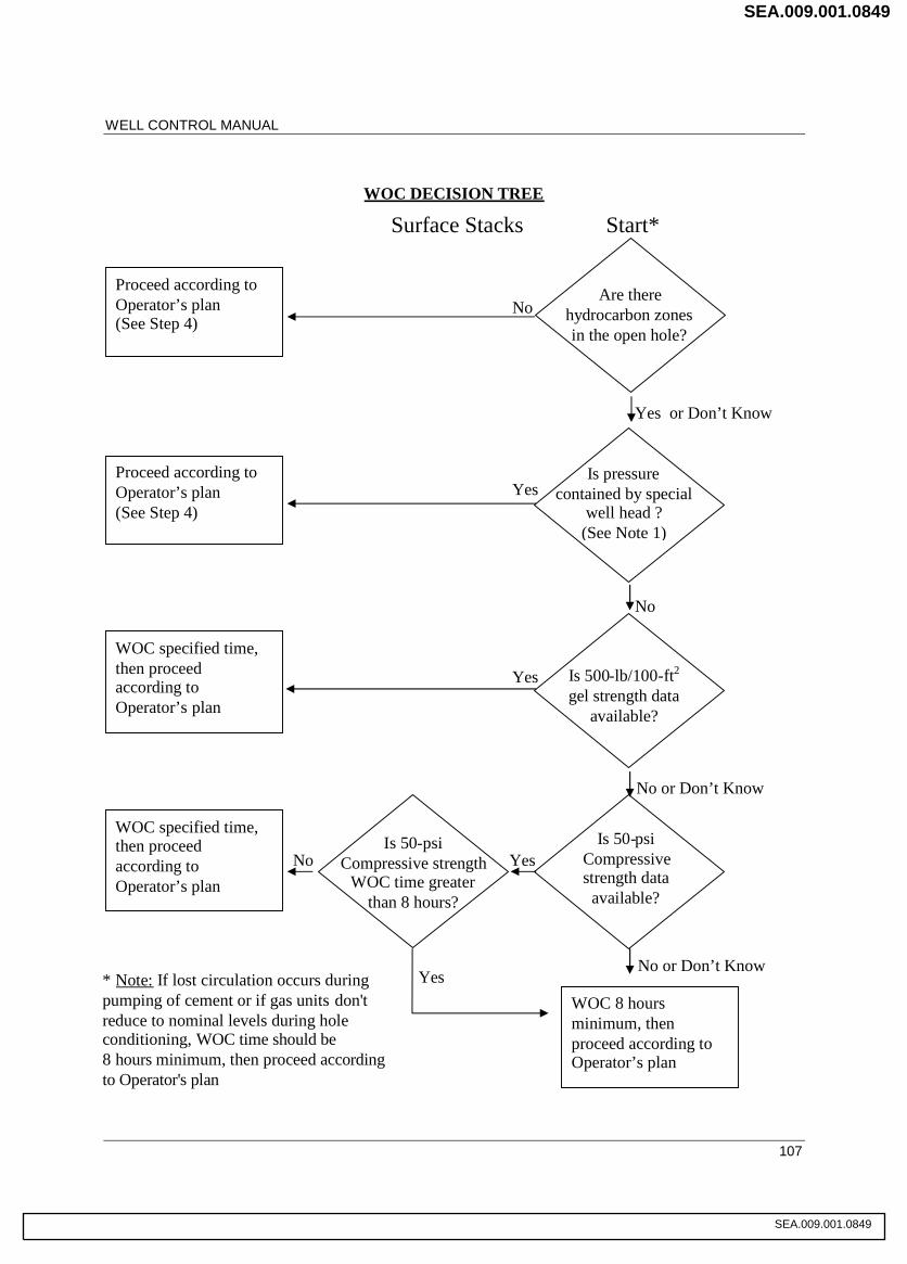
WELL CONTROL MANUAL
107
WOC DECISION TREE
Proceed according toOperator’s plan(See Step 4)
Proceed according toOperator’s plan(See Step 4)
WOC specified time,then proceedaccording toOperator’s plan
WOC specified time,then proceedaccording toOperator’s plan
Are therehydrocarbon zonesin the open hole?
Is pressurecontained by special
well head ?(See Note 1)
Is 500-lb/100-ft2
gel strength dataavailable?
Is 50-psiCompressivestrength data
available?
WOC 8 hoursminimum, thenproceed according toOperator’s plan
No or Don’t Know
No or Don’t Know
No
Yes or Don’t Know
Is 50-psiCompressive strength
WOC time greaterthan 8 hours?
No
No
Yes
Yes
Yes
Yes
Surface Stacks Start*
* Note: If lost circulation occurs duringpumping of cement or if gas units don'treduce to nominal levels during holeconditioning, WOC time should be8 hours minimum, then proceed accordingto Operator's plan
SEA.009.001.0849
SEA.009.001.0849
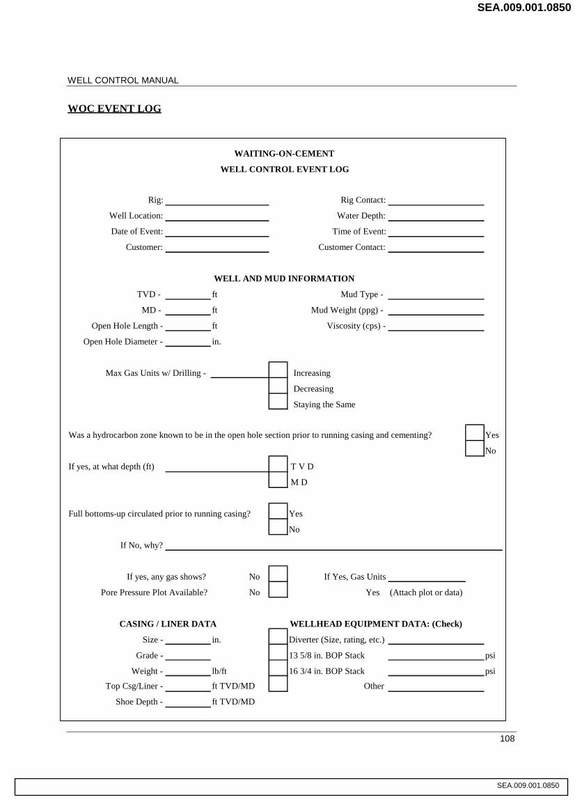
WELL CONTROL MANUAL
108
WOC EVENT LOG
WAITING-ON-CEMENT
WELL CONTROL EVENT LOG
Rig: Rig Contact:
Well Location: Water Depth:
Date of Event: Time of Event:
Customer: Customer Contact:
WELL AND MUD INFORMATION
TVD - ft Mud Type -
MD - ft Mud Weight (ppg) -
Open Hole Length - ft Viscosity (cps) -
Open Hole Diameter - in.
Increasing
Decreasing
Staying the Same
Was a hydrocarbon zone known to be in the open hole section prior to running casing and cementing? Yes
No
If yes, at what depth (ft) T V D
M D
Full bottoms-up circulated prior to running casing? Yes
No
If No, why?
No If Yes, Gas Units
No Yes (Attach plot or data)
CASING / LINER DATA WELLHEAD EQUIPMENT DATA: (Check)
Size - in. Diverter (Size, rating, etc.)
Grade - 13 5/8 in. BOP Stack psi
Weight - lb/ft 16 3/4 in. BOP Stack psi
Top Csg/Liner - ft TVD/MD Other
Shoe Depth - ft TVD/MD
Pore Pressure Plot Available?
If yes, any gas shows?
Max Gas Units w/ Drilling -
SEA.009.001.0850
SEA.009.001.0850

WELL CONTROL MANUAL
109
CEMENT DATA
Cement Supplier:
Slurry Density:
Cement laboratory test data: (Attach test data sheet if available)
CEMENT PLACEMENT DATA
Pumping time -
Pump capacity -
Description of slurry and cement placement: (Tops of slurry and cement, returns identified, etc.)
FLOW INFORMATION
How long was cement was in place before flowing?
Was there a surface sample and what were its characteristics at time of flow detection? Yes
No
Lot or Slurry Identification No.:
What remedial action was taken to mitigate the problem? (Be specific: diverted, shut-in with what pressures showing,action taken, time resolved, etc.)
Observed indicators of well flow when detected: (how noticed and be specific)
Designed length of transitions time -
Time started pumping -
Volume pumped -
Strokes pumped -
Pre-sweep slurry -
Volume -
Fluid properties (density, viscosity, etc.) -
Time to reach 500-lb/100ft2 gel strength -
Time to reach 50 psi compressive strength -
Designed placement time -
Designed start time for transition -
SEA.009.001.0851
SEA.009.001.0851

WELL CONTROL MANUAL
110
APPENDICES
SEA.009.001.0852
SEA.009.001.0852

WELL CONTROL MANUAL
111
APPENDIX A
TERMS AND ABBREVIATIONSBBL BarrelsBHA Bottom Hole AssemblyBHP Bottom Hole PressureBOP Blowout PreventionCLF Choke Line FrictionCO2 Carbon DioxideCSON Continental Shelf Operations NoticeECD Equivalent Circulating DensityEMW Equivalent Mud WeightFCP Final Circulating MaterialH2S Hydrogen SulphideHDIS Hydril Drop In SubHP High PressureHT High TemperatureHWDP Heavy Weight Drill PipeIADC International Association of Drilling ContractorsIBOP Inside Blow Out PreventerICP Initial Circulating PressureID Inside DiameterKR Kill RatesLCM Loss Circulation MaterialLMRP Lower Marine Riser PackageMAASP Maximum Allowable Annular Surface PressureMACP Maximum Allowable Casing PressureMD Measured DepthMSS Multi Shot SurveyMW Mud WeightOBM Oil Based MudOD Outside DiameterOIM Offshore Installation ManagerPPG Pounds per gallonPSI Pounds per square inchPVT Pit Volume TotaliserROP Rate of PenetrationROV Remote Operational VehicleSCR Slow Circulating RatesSG Specific GravitySI Statutory InstrumentSIDPP Shut in Drill Pipe PressureSPM Strokes per minuteSPR Slow Pump RatesTD Theoretical DepthTVD True Vertical Depth
SEA.009.001.0853
SEA.009.001.0853
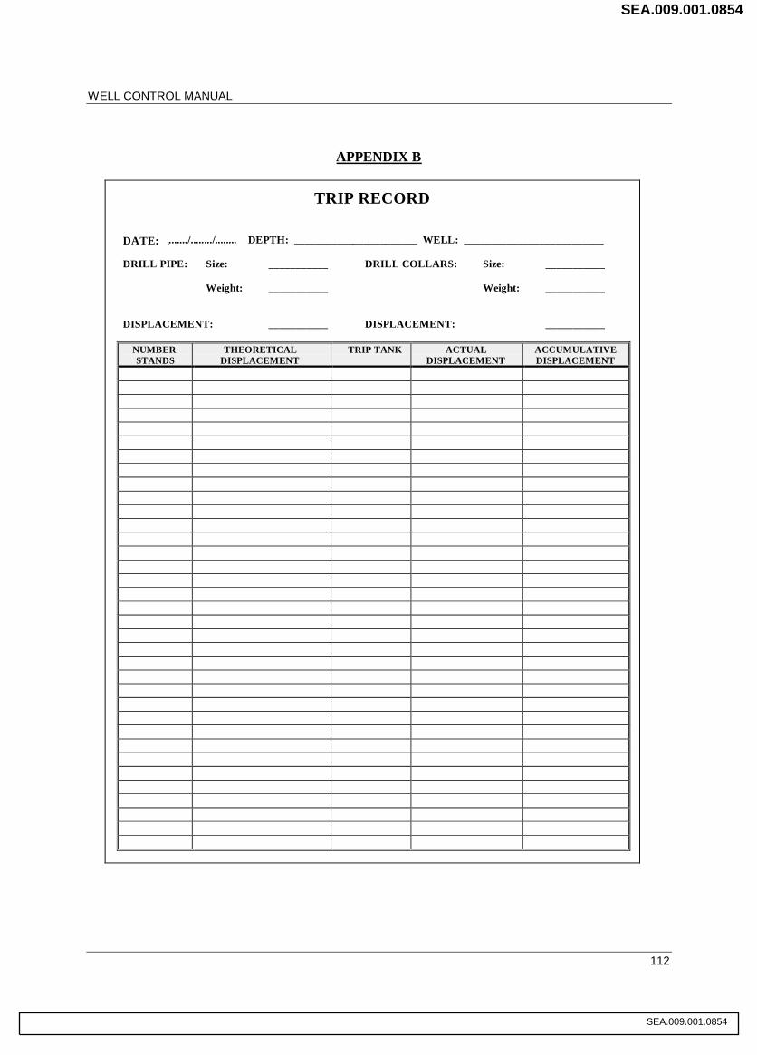
WELL CONTROL MANUAL
112
APPENDIX B
TRIP RECORD
DATE: ......../......../........ DEPTH: _______________________ WELL: __________________________
DRILL PIPE: Size: ___________ DRILL COLLARS: Size: ___________
Weight: ___________ Weight: ___________
DISPLACEMENT: ___________ DISPLACEMENT: ___________
NUMBERSTANDS
THEORETICALDISPLACEMENT
TRIP TANK ACTUALDISPLACEMENT
ACCUMULATIVEDISPLACEMENT
SEA.009.001.0854
SEA.009.001.0854
WELL CONTROL MANUAL
113
APPENDIX C
1. WELL CONTROL KILL SHEET SUBSEA
2. WELL CONTROL KILL SHEET SURFACE
SEE ATTACHED DOCUMENTS
SEA.009.001.0855
SEA.009.001.0855

DATE :
UNITS : FIELD
FORMATION STRENGTH DATA: CURRENT WELL DATA:
SURFACE LEAK-OFF PRESSURE FROM MARINE RISER
FORMATION STRENGTH TEST (A) psi LENGTH ft
DRILLING FLUID DENS. AT TEST (B) ppg CHOKELINE
LENGTH ft
MAX. ALLOWABLE DRILLING FLUID DENSITY =
(A) psi ÷ 0.05 ÷ SHOE TVD + (B) ppg = (C) ppg DRILLING FLUID DATA
÷ 0.05 ÷ + = (C) DENSITY ppg
GRADIENT psi/ft
INITIAL MAASP = ( (C) ppg - CURR DENS ) x SHOE TVD x 0.05
= ( - ) x x 0.05
= psi CASING & SHOE DATA
SIZE in
M. DEPT ft
T.V. DEPT ft
PUMP NO. 1 DISPL PUMP NO. 2 DISPL
bbl / stk bbl / stk
HOLE DATA
SIZE in
M. DEPTH ft
T.V. DEPTH ft
SPM
SPM
PRE-RECORDED VOLUME DATA :
x =
x = +
x = +
( D ) bbl ( E ) stks min
x =
x = +
( F ) bbl stks min
x = ( G ) + stks min
x = ( H ) + stks min
( F + G+ H ) = ( I ) bbl stks min
( D + I ) = ( J ) bbl stks min
( K ) bbl stks
( J + K ) bbl stks
x = bbl stks
CALCULATIONS CAN BE MADE USING EITHER DRILLING FLUID DENSITY OR DRILLING FLUID GRADIENT
IWCF CERTIFICATION TESTSUBSEA BOP KILL SHEET
ft
LENGTH CAPACITY
bbl / ft
NAME :
VOLUME
PUMP DISPLACEMENT
bbl
PUMP STROKES
stks
MARINE RISER x DP
TOTAL ANNULUS / CHOKELINE VOL.
TOTAL WELL SYSTEM VOLUME
ACTIVE SURFACE VOLUME
TOTAL ACTIVE FLUID SYSTEM
CHOKELINE
DC x OPEN HOLE
DP/HWDP x OPEN HOLE
OPEN HOLE VOLUME
DP x CASING
PUMP STROKES
SLOW PUMP RATE
DRILL PIPE
HEVI WATE
DRILL COLLAR
DRILL STRING VOLUME
TIME
minutes
VOLUME
DYNAMIC PRESSURE LOSS psi
PUMP NO. 2
RISER CHOKELINE CL. FRICT
SLOW PUMPRATE DATA
RISER CHOKELINE CL. FRICT
PUMP NO. 1
SEA.009.001.0856
SEA.009.001.0856

DATE :
UNITS : FIELD
KICK DATA:
SHUT IN DRILL PIPE PRESSURE -------- SIDPP psi
SHUT IN CASING PRESSURE -------- SICP psi
PH GAIN bbl
1 bbl = 42 US gall
KILL FLUID DENSITY SIDPP ÷ TVD ÷ + CURRENT DRILLING FLUID DENSITY
÷ ÷ + ppg = ppg
KILL FLUID GRADIENT CURRENT DRILLING FLUID GRADIENT + SIDPP
TVD˙̇̇˙̇̇˙̇̇ ˙̇̇˙̇̇
.................. psi / ft
INITIAL CIRCULATING PRESS. DYNAMIC PRESSURE LOSS THROUGH RISER CIRCUIT + SIDPP
ICP
+ = psi
INITIAL DYNAMIC CASING SICP - CHOKE LINE FRICTION
PRESS AT KILL PUMP RATE
- = psi
FINAL CIRCULATING PRESS x DYN. PRESS. LOSS RISER CIRC.
FCP CURRENT DRILLING FLUID DENSITY
.................. x =
.................. psi
FINAL CIRCULATING PRESS. x DYN. PRESS. LOSS RISER CIRC.
FCP CURRENT DRILLING FLUID DENSITY
.................. x =
.................. psi
( L ) = ICP - FCP = - = psi ( L ) x 100 ................. x 100 psi / 100 strokes
STROKES PRESSURE
0
+ =
KILL FLUID DENSITY
KILL FLUID GRADIENT
( E )=
.................=
NAME :
IWCF CERTIFICATION TESTSUBSEA BOP KILL SHEET
0.052
0.052
STATIC
&
DYNAMIC
DRILL
PIPE
PRESSURE
STROKES
SEA.009.001.0857
SEA.009.001.0857

PAGE 1 OF 2
FORMATION STRENGHT DATA CURRENT WELL DATA
DRILLING FLUID DATA
psi DENSITY sg
.
sg GRADIENT bar/m
sg DP
psi DC
CASING AND SHOE DATA
SIZE in
M. DEPTH m
T.V. DEPTH m
HOLE DATA
SLOW PUMP SIZE in 900RATE DATA
psi psi M. DEPTH m
psi psi T.V. DEPTH m
PRE-RECORDED PUMP STROKESVOLUME DATA stks
VOLUMEPUMP DISPL.
DRILL COLLAR
DC x OPEN HOLE
HW x OPEN HOLE
DP x OPEN HOLE
DP x CASING
CALCULATIONS CAN BE MADE USING EITHER DRILLING FLUID DENSITY OR DRILLING FLUID GRADIENT
HEVI WATE
DRILL PIPE
TOTAL ACTIVE FLUID SYSTEM (I+J)=
TOTAL WELL SYSTEM VOLUME (D+H)=(I)
ACTIVE SURFACE VOLUME (J)=
OPEN HOLE VOLUME
DRILL STRING VOLUME
TIMEminutes
PUMP STROKESSLOW PUM RATE
VOLUMEL
LENGTHm
CAPACITYl / m
DYNAMIC PRESSURE LOSSPUMP NO. PUMP NO.
IWCF CERTIFICATION TESTSURFACE BOP KILL SHEET
PUMP NO. DISPLACEMENT PUMP NO. DISPLACEMENT
SURFACE LEAK-OFF PRESSUREFROM FORMATION STREGHT TEST
DRILLING FLUID DENSITY AT TEST
MAX ALLOWABLE DRILLING FLUIDDENSITY
INITIAL MAASP
TOTAL ANNULUS VOLUME (F+G)=(H)
l/stk12.46 l/stk
x
x
x
=
=
=
stks min
x =
x =
L
x =(G)
L
L
L
L
minstks
DATE: _________________________NAME: __________________________UNITS: FIELD
(D)(E)
(F) L
=
stks
stks
stks
stks
stks
minstks
minstks
minstks
SPM
SPM
m
m
x =
stksstks
stksstksstksstks
L
+
+
=
+
+
=
IWCF Kill Sheet.xlsSEA.009.001.0858
SEA.009.001.0858

KIK DATA
SHUT IN DRILL PIPES PRESSURE SIDPP bar
SHUT IN DRILL CASING PRESSURE SICP bar
PIT GAIN L
KILL FLUID DENSITY CURRENT DRILLING FLUID DENSITY +TVD
+ =
KILL FLUID GRADIENT CURRENT DRILLING FLUID GRADIENT +
+ =
INITIAL CIRCULATING PRESS. DYNAMIC PRESSURE LOSS + SIDPPICP
+ = bar
FINAL CIRCULATING PRESS.FCP
barx =
x 100(K) = ICP - FCP = - = psi = =
bar
bar / m
IWCF CERTIFICATION TESTSURFACE BOP KILL SHEET
x 10.2
psi/100strokes
STROKES PRESSURE
DATE: _____________________________NAME: _____________________________UNITS: FIELD
SIDPP x 10.2
SIDPP
TVD
KILL FLUID DENSITY
CURRENT DRILLING FLUID DENSITYx DINAMIC PRESSURE LOSS
(K) x 100
(E)
0.00
0.10
0.20
0.30
0.40
0.50
0.60
0.70
0.80
0.90
1.00
0 200 400 600 800 1000 1200 1400 1600 1800 2000
IWCF KILL SHEET SurfaceSEA.009.001.0859
SEA.009.001.0859
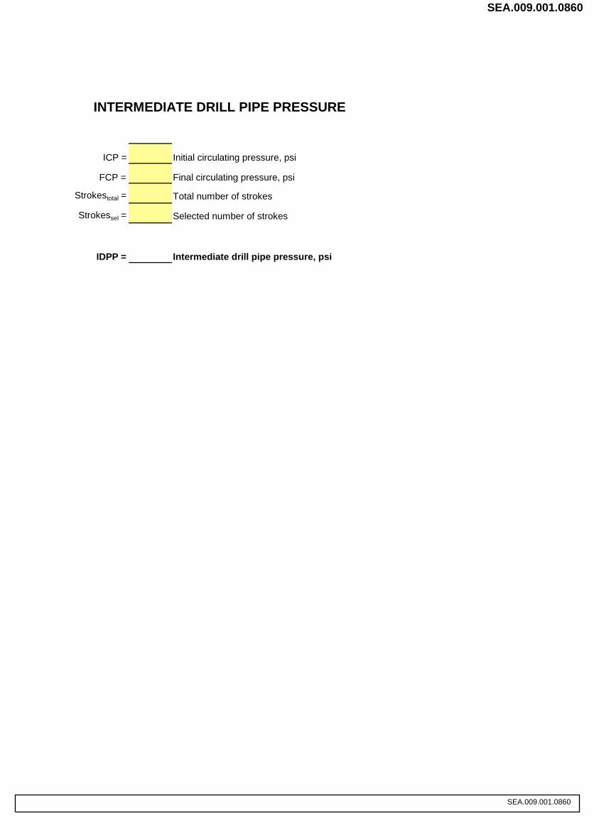
ICP = Initial circulating pressure, psi
FCP = Final circulating pressure, psi
Strokestotal = Total number of strokes
Strokessel = Selected number of strokes
IDPP = Intermediate drill pipe pressure, psi
INTERMEDIATE DRILL PIPE PRESSURE
SEA.009.001.0860
SEA.009.001.0860

Page 3 of 4
PRESSURE CHART
STROKES PRESSUREICP
BIT FCP
Surface to Bit Strokes ÷ 10 = Strokes per Step ICP - FCP = PSI DROP ÷ 10 = PSI per Step
PRESSURE CHART
To fill in the pressure chart calculate the incremental steps using the formulas atthe bottom of the chart
IWCF KILL SHEET Surface
SEA.009.001.0861
SEA.009.001.0861
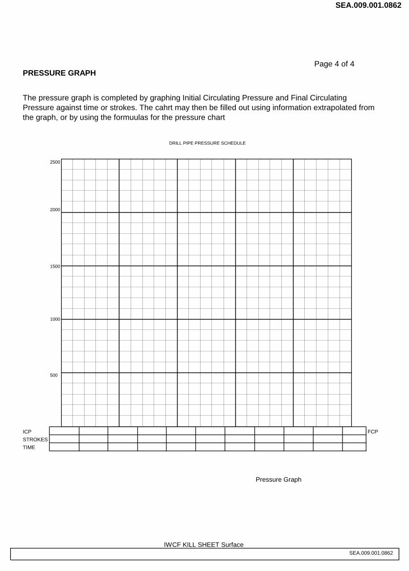
Page 4 of 4PRESSURE GRAPH
2500
2000
1500
1000
500
ICP FCPSTROKESTIME
Pressure Graph
The pressure graph is completed by graphing Initial Circulating Pressure and Final CirculatingPressure against time or strokes. The cahrt may then be filled out using information extrapolated fromthe graph, or by using the formuulas for the pressure chart
DRILL PIPE PRESSURE SCHEDULE
IWCF KILL SHEET SurfaceSEA.009.001.0862
SEA.009.001.0862

x 100(K) = ICP - FCP = - psi = =
STROKES
psi/100strokes
STROKES PRESSURE
IWCF CERTIFICATION TESTSURFACE BOP KILL SHEET
ST
ATI
C&
DIN
AM
ICD
RIL
LP
IPE
PR
ES
SU
RE
DATE: __________________________NAME: __________________________UNITS: FIELD
(K) x 100
(E)
IWCF KILL SHEET SurfaceSEA.009.001.0863
SEA.009.001.0863