Embed Size (px)
Citation preview

1
Revision A 999279
www.teraflex.com
TeraFlex Premium TJ/YJ/XJ/ZJ Dana
30/44 Ball Joints Install Instructions
Important Notes:
Prior to beginning this or any installation read these instructions to familiarize yourself with the required steps and evaluate if you are experienced and capable to personally perform these modifications. A factory service manual should be used in conjunction with these installation in-structions.
Follow these instructions exactly: The orientation of the TeraFlex Lower Ball Joints is critical for proper function and future adjustability.
If the ball joints being replaced are knurled, then they must be replaced with knurled ball
joints (Knurled Ball Joint Kit # 1355300).
Refer to the parts list to ensure that all necessary components and hardware has been included. If any parts are missing please contact your local TeraFlex dealer for assistance.
Tools needed: This installation guide Basic mechanics tool set Ball Joint Press
Grease Gun/High Quality Grease Blue thread locking compound Large Hammer
#1355100
#1355300 (Knurled)

www.teraflex.com
2
Revision A 999279
ITEM NO. PART # 355100 Non-Knurled Set DESCRIPTION QTY.
1 345007 JK Dana 30/44 Premium Series Lower Ball Joint Adjusting Tool 1
2 355110 TJ/YJ/XJ/ZJ Dana 30/44 Premium Series Lower Ball Joint 2
3 355010 TJ/YJ/XJ/ZJ Dana 30/44 Premium Series Upper Ball Joint 2
4 279 Nut 9/16"-18 UNF Black Castle Nut 2
5 301 Cotter Pin 3/32" Diameter x 1.25" Long 4
6 308 Grease Zerk 1/4"-28 UNF Straight 6
7 344206 Nut 5/8"-18 UNF Flanged Serrated Castle Nut 2
ITEM NO. PART # 355300 Knurled Set DESCRIPTION QTY.
1 345007 JK Dana 30/44 Premium Series Lower Ball Joint Adjusting Tool 1
2 355310 TJ/YJ/XJ/ZJ Dana 30/44 Knurled Premium Series Lower Ball Joint 2
3 355320 TJ/YJ/XJ/ZJ Dana 30/44 Knurled Premium Series Upper Ball Joint 2
4 279 Nut 9/16"-18 UNF Black Castle Nut 2
5 301 Cotter Pin 3/32" Diameter x 1.25" Long 4
6 308 Grease Zerk 1/4"-28 UNF Straight 6
7 344206 Nut 5/8"-18 UNF Flanged Serrated Castle Nut 2
3 www.teraflex.com
Revision A 999279
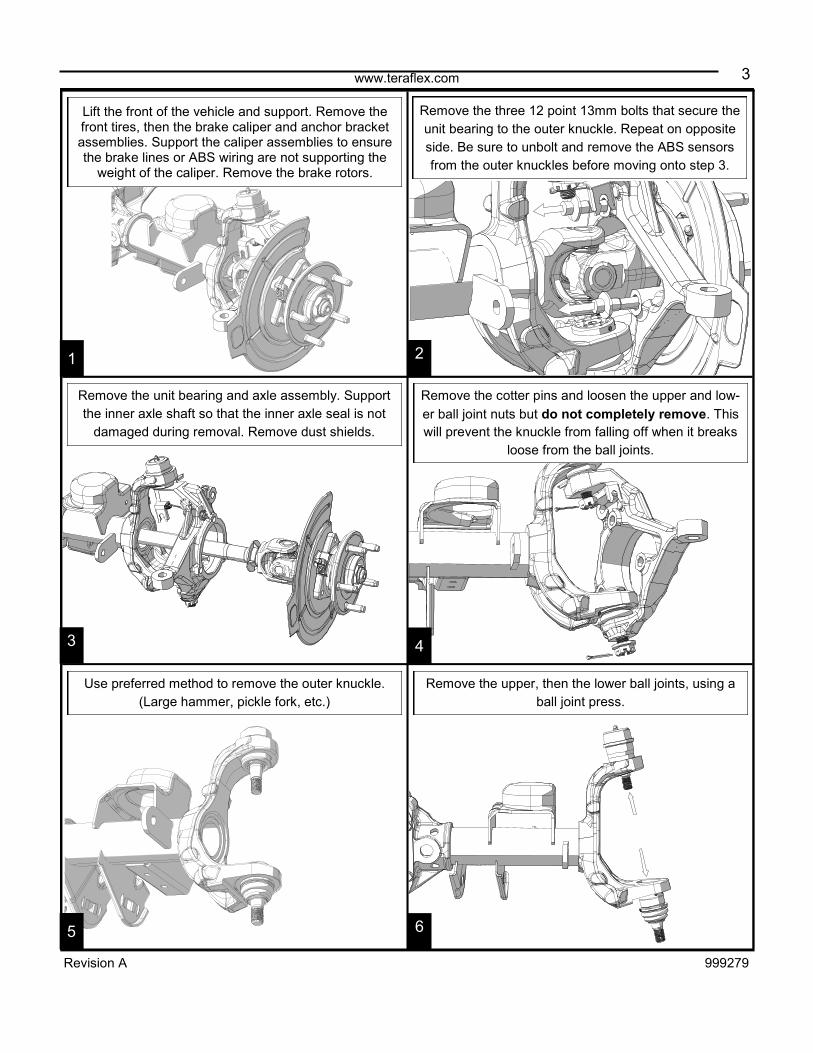
Lift the front of the vehicle and support. Remove the front tires, then the brake caliper and anchor bracket assemblies. Support the caliper assemblies to ensure the brake lines or ABS wiring are not supporting the
weight of the caliper. Remove the brake rotors.
Use preferred method to remove the outer knuckle.
(Large hammer, pickle fork, etc.)
Remove the upper, then the lower ball joints, using a
ball joint press.
1 2
6 5
4 3
Remove the three 12 point 13mm bolts that secure the
unit bearing to the outer knuckle. Repeat on opposite
side. Be sure to unbolt and remove the ABS sensors
from the outer knuckles before moving onto step 3.
Remove the unit bearing and axle assembly. Support
the inner axle shaft so that the inner axle seal is not
damaged during removal. Remove dust shields.
Remove the cotter pins and loosen the upper and low-
er ball joint nuts but do not completely remove. This
will prevent the knuckle from falling off when it breaks
loose from the ball joints.
4 www.teraflex.com
Revision A 999279
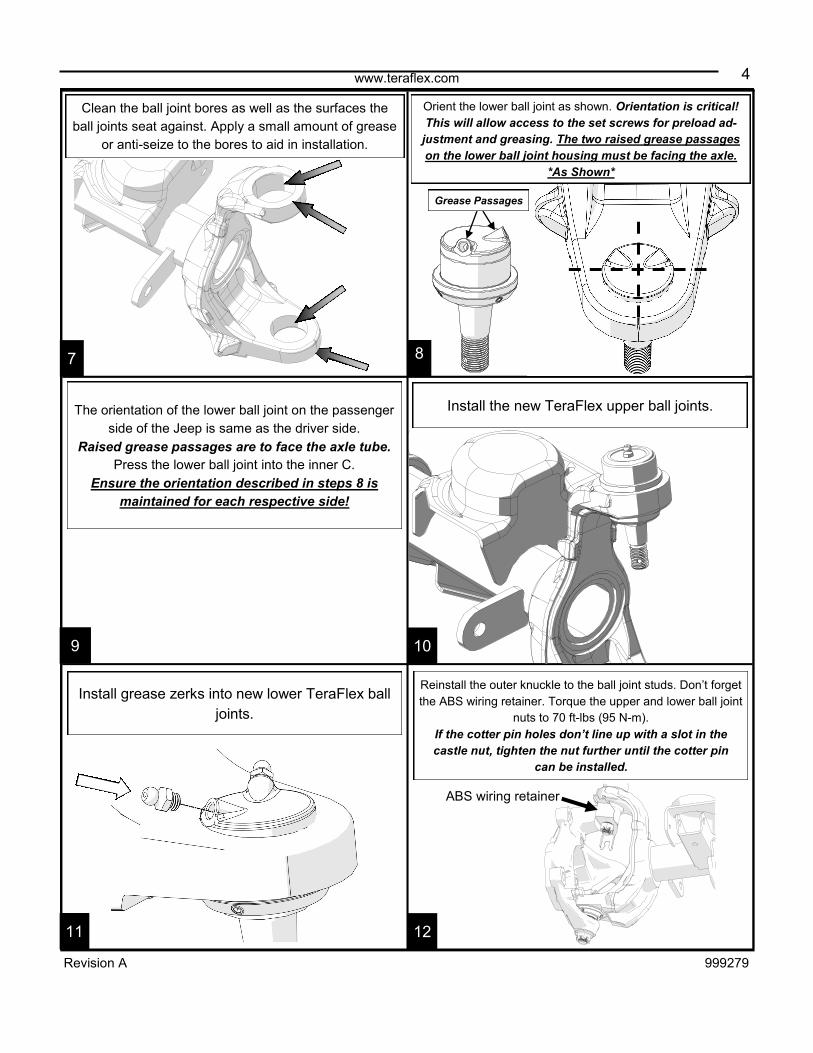
Reinstall the outer knuckle to the ball joint studs. Don’t forget
the ABS wiring retainer. Torque the upper and lower ball joint
nuts to 70 ft-lbs (95 N-m).
If the cotter pin holes don’t line up with a slot in the
castle nut, tighten the nut further until the cotter pin
can be installed.
7 8
12 11
10 9
Install the new TeraFlex upper ball joints. The orientation of the lower ball joint on the passenger
side of the Jeep is same as the driver side.
Raised grease passages are to face the axle tube.
Press the lower ball joint into the inner C.
Ensure the orientation described in steps 8 is
maintained for each respective side!
Install grease zerks into new lower TeraFlex ball
joints.
Grease Passages
Clean the ball joint bores as well as the surfaces the
ball joints seat against. Apply a small amount of grease
or anti-seize to the bores to aid in installation.
ABS wiring retainer
Orient the lower ball joint as shown. Orientation is critical!
This will allow access to the set screws for preload ad-
justment and greasing. The two raised grease passages
on the lower ball joint housing must be facing the axle.
*As Shown*
5 www.teraflex.com
Revision A 999279
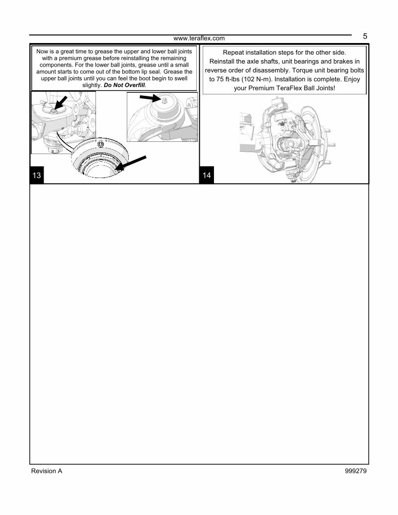
Now is a great time to grease the upper and lower ball joints with a premium grease before reinstalling the remaining
components. For the lower ball joints, grease until a small amount starts to come out of the bottom lip seal. Grease the
upper ball joints until you can feel the boot begin to swell slightly. Do Not Overfill.
Repeat installation steps for the other side.
Reinstall the axle shafts, unit bearings and brakes in
reverse order of disassembly. Torque unit bearing bolts
to 75 ft-lbs (102 N-m). Installation is complete. Enjoy
your Premium TeraFlex Ball Joints!
13 14

6 www.teraflex.com
Revision A 999279
Use the supplied specialty wrench and an inch pounds
torque wrench to tighten the lower ball joint’s preload
adjustment nut. Torque to 70 in-lbs (8 N-m).
Tighten the three set screws.
Torque to 30 in-lbs (4 N-m).
The new Premium Lower Ball Joints are
designed with an adjustable preload ring. If
excessive wear becomes apparent and falls
out of factory specs (refer to your factory ser-
vice manual), use the following instructions to
tighten the preload.
This process should be done with the ball
joints under load, with the wheels on the
ground. Removal of wheels and other compo-
nents are not necessary for this process.
The following are steps for servicing
your new Premium Ball Joints.
1
2
1
Grease both upper and lower ball joints at
every oil change interval.
For the lower ball joints, grease until a small amount starts to come out of the bottom lip seal. For the upper ball joints, grease until you can feel
the boot begin to slightly swell.
Loosen the three set screws at the base of
the lower ball joint (DO NOT REMOVE). To gain access to the
side set screws turn the tires to the left. Loosen the accessible
set screws (front drivers side, rear passenger side) 1 to 2
turns. Then turn the tires to the right for access to the remain-
ing set screws (rear drivers side, front passenger side).
www.teraflex.com
7
Revision A 999279
TERAFLEX, Inc. 5680 West Dannon Way West Jordan, Utah 84081 Phone/801.713.3314 Fax/801.713.2313 www.teraflex.com
PRODUCT INFORMATION MAINTENANCE INFORMATION:
It is the buyer’s responsibility to have all suspension, drivetrain, steering, and other components checked for proper tightness and torque after the first 100 miles
and every 3000 miles after that.
NOTICE TO INSTALLER:
The enclosed “Warning to Driver” sticker must be installed in the vehicle in driver’s view. This sticker is to act as a constant safety reminder when operating the
vehicle. It is your responsibility as the equipment installer to install the provided sticker and to forward the product instructions to the vehicle’s owner for review. If a
“Warning to Driver” sticker or product installation guide were not included in the kit, FREE replacement stickers and instructions are available by request. It is the
installer’s duty to ensure a safe and controllable vehicle after the modifications have been performed.
WARNING:
Neither the seller nor the manufacturer will be liable for any loss, damage, or injury directly or indirectly arising from the use of or inability to determine the use of
these products. Before using, the user shall determine the suitability of the products for its intended use, and the user shall assume all responsibility and risk in
connection therewith.
WARNING TO DRIVER:
This vehicle has been modified to enhance off road performance and has unique handling characteristics. Use in harsh environments can cause extreme stress on
the components. Vehicle should be inspected after being off road to make sure that all the components are in working order and safe to travel on the highway. All
fasteners should be checked so that they are at the correct torque specifications as the vibration and stresses from off roading may cause critical fasteners to work
loose. Extra care should be taken to inspect the critical components, steering, and brake systems. During each oil change components such as arms, tie rod ends,
etc should be greased and checked for excessive wear. Any worn components should be replaced. When returning to the pavement always set or restore tire air
pressure to the factory recommendation and connect or engage any disabled sway bar mechanisms. Because of the higher center of gravity and larger tires, this
vehicle handles and reacts differently than many passenger cars, both on and off road. You must drive it safely! Extreme care should be taken to prevent vehicle
rollover or loss of control, which can result in serious injury or death. Avoid sudden sharp turns or abrupt maneuvers. Generally, braking performance and capabili-
ties are decreased when significantly larger/heavier tires are used, especially when used in combination with transfer case low-range reduction kits. Take this into
consideration while driving. Do not add, alter or fabricate any factory or aftermarket parts to increase vehicle height over the intended height of the TeraFlex prod-
uct purchased. Mixing component brand is not recommended. TeraFlex Inc. will not be responsible for any altered product or any improper installation or use of
our products. We will be happy to answer any questions concerning the design, function, and correct use of our products. It is ultimately the buyer’s responsibility
to have all bolts/nuts checked for tightness after the first 100 miles and then every 3000 miles. Wheel alignment, steering system, suspension and drive line sys-
tems must be inspected by a qualified professional mechanic at least every 3000 miles.
TERAFLEX PRODUCT WARRANTY:
TeraFlex Inc. warrants TeraFlex Suspension products to the original retail purchaser to be free of defects in material and workmanship for as long as the original
purchaser owns the vehicle on which products were originally installed.
Failure to complete regular maintenance (grease every 3000 miles) on TeraFlex FlexArms will void this warranty. All other conditions of the standard TeraFlex
product warranty apply.
All TeraLow products are covered by the TeraFlex two (2) year warranty to be free of defects in material and workmanship for two years from date purchased.
TeraFlex axles are covered by a 12-month warranty to be free of defects in materials and workmanship.
This warranty does not cover or include product finish, improperly installed or applied products, improperly maintained products, products or components used for
racing or competition or damage due to abuse or neglect, products that fail due to the use of larger tire and wheel combinations.
All returns must be accompanied by an original invoice. It is the customer’s responsibility to remove the product from the vehicle. Shipping charges are the respon-
sibility of the customer. TeraFlex Inc. will pay the return freight if the product meets the terms of warranty.
This warranty is for the replacement or repair of defective TeraFlex products only and does not include freight charges, labor charges for removal of or installation
of TeraFlex or related products or components, costs incurred due to down time of the vehicle, or lost profits due to vehicle down time.
A returned goods authorization number (RGA#) must accompany any returned products. For more information please contact a TeraFlex customer service repre-
sentative.
COPYRIGHT
©Copyright 2014. All rights reserved, TeraFlex Inc. Reproduction of this catalog and/or any of its contents without written permission is strictly prohibited.
TeraFlex® is a registered trademark of TeraFlex Inc. All trade names and logos including but not limited to TeraFlex, FlexArms, RockGuard, Monster, and LCG
are protected by law and duplication of trade names and/or logos are strictly prohibited.
TeraFlex Inc. reserves the right to update, discontinue, redesign, modify finish, part number or component build parts if deemed necessary without written notice.
TeraFlex Inc., and any associated dealers are not responsible for misprints or typographical errors that may have inadvertently been made within this instruction
sheet.
Jeep® and the Jeep® grill are registered trademarks of Fiat Chrysler Automobiles N.V., and have no affiliation with TeraFlex Inc.


![eLd]Zj/ gu/kflnsf, cfly{s P]g@)&& eLd]Zj/ gu/kflnsf](https://img.dokumen.tips/doc/110x75/62833498132d5a321a51fa43/eldzj-gukflnsf-cflys-pgampamp-eldzj-gukflnsf.jpg)