Embed Size (px)
Citation preview
1. SCOPE
This part of EN755 specifies the tolerance on dimensions & form for aluminum & aluminum alloy extruded profile with
cross section contained within a circumscribing circle not greater than 800 mm.(Fig 1).
C 800
Note: This standard applies to extruded profiles for general engineering applications only.
Fig 1-Circumscribing circle.
2. ALLOY
EN AE-1050A, EN AW-1070A, EN AW-1200, EN AW-1350, EN AW-3003, EN AW-3103,EN AW-5005, EN AW-5005A, EN
AW-6101A, EN AW-6101B, AN AW6005, EN AW-6005A, EN AW-6106, EN AW-6008, EN AW-6060, EN AW-6063, EN
AW-6363A, EN AW-6463
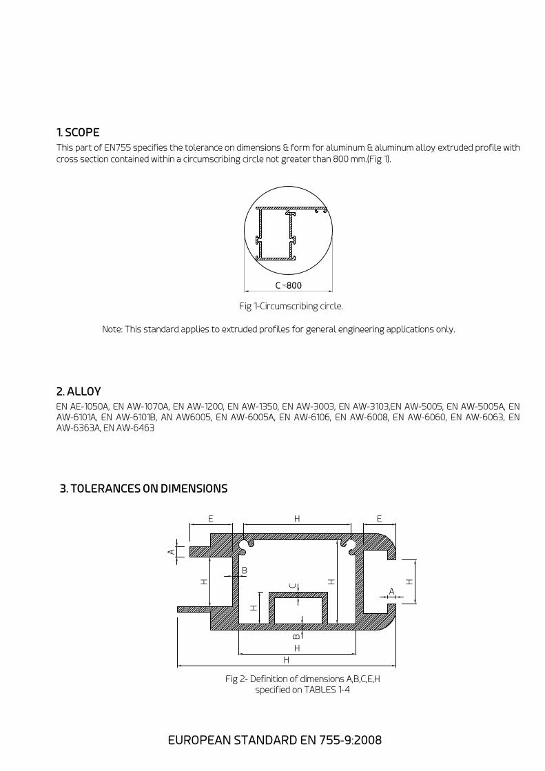
Fig 2- Definition of dimensions A,B,C,E,H
specified on TABLES 1-4
A
E H E
H
A
H
C
B
H
B
H
H
3. TOLERANCES ON DIMENSIONS
EUROPEAN STANDARD EN 755-9:2008
H

3.1.1 Cross-sectional dimensions(Fig 2)
A: wall thickness except those enclosing the hollow spaces in the below profiles.
B: wall thickness enclosing the hollow spaces in hollow profiles except those between two spaces hollow spaces.
C: wall thickness between two hollow spaces in hollow profiles.
E: the length of the shorter leg of profiles with with open ends.
H: all dimensions except wall thickness.
3.1.2 Tolerances on dimensions other than wall thickness.
The tolerance on dimensions shall be as specified in table 1. for profiles with open ends(see Fig 3,4 & the relevant
examples)the tolerance specified in table 2 shall be added to those of table 1 for dimensions H across open ended
l e g s i n o r d e r t o o b t a i n t h e t o l e r a n c e o n t h e g a p b e t w e e n a n y o p p o s i t e p o i n t s o n t h e s e e n d s .
TABLE 1: Tolerance on cross-sectional dimension of solid & hollow profiles.
Dimension H
Over
Up to &
including
Tolerances on H for circumscribing circle CD*
CD<100
100<CD
<200
-
10
25
50
100
150
200<CD
<300
10
25
50
100
150
200
0.25
0.30
0.50
0.70
-
-
0.30
0.40
0.60
0.90
1.10
1.30
0.35
0.50
0.80
1.10
1.30
1.50
* These tolerances do not apply to tempers O & Tx510. for these tempers, the tolerances shall be
subject to agreement between the supplier & the purchaser.
*for Profiles with open ends, see Fig 3 & 4, tolerances for H in the area of open ends shall be increased
by values specified in TABLE 2.
TABLE 2: Additions to the tolerance on cross-sectional dimension H of solid & hollow profiles
with open ends.
Dimension E
Over
Up to &
including
Additions to the tolerances on H in tables 1 for
dimensions across the ends of open ended
profiles.
-
20
30
40
60
80
100
125
150
180
20
30
40
60
80
100
125
150
180
210
-
0.15
0.25
0.40
0.50
0.60
0.80
1.00
1.20
1.40
EUROPEAN STANDARD EN 755-9:2008

Fig 3 below shows open end on hollow profiles. The determination on tolerance on cross sectional
dimensions H is shown in the following calculation example.
Example of the tolerance across open ended profiles.
Example 1
Dimension H: 20mm
Dimension E: 100mm
Circumscribing circle CD 100mm to 200mm.
The tolerance on H according to table 1 is ±0.40mm :plus the additional tolerance according to TABLE 2 which is
±0.60mm; total tolerance on H is ±1.00mm.
H
E
Fig 3-Hollow profile with open end
3.1.3 Tolerances on wall thickness of solid & hollow profiles
The tolerance on wall thickness of solid & hollow profiles shall be specified in table 3
TABLE 3: Tolerances on wall thickness for the profiles with a circumscribing circle up to &
including 300mm
Nominal wall thickness
A, B or C
Over
Up to &
including
Tolerances on wall thickness
CD<100
100<CD
<300
-
1.5
3
6
10
15
20
30
40
1.5
3
6
10
15
20
30
40
50
0.15
0.15
0.20
0.25
0.30
0.35
0.40
0.45
-
0.20
0.25
0.30
0.35
0.40
0.45
0.50
0.60
0.70
0.20
0.25
0.40
0.60
0.80
1.20
1.50
-
-
Wall thickness A
Circumscribing circle
CD<100
100<CD
<300
CD<100
100<CD
<300
Wall thickness B*
Circumscribing circle
Wall thickness C
Circumscribing circle
0.30
0.40
0.60
0.80
1.00
1.50
1.80
2.00
-
0.25
0.30
0.50
0.75
1.00
1.50
1.90
-
-
0.35
0.50
0.75
1.00
1.20
1.90
2.20
2.50
-
* For seamless hollow profile the tolerance given for wall thickness B shall apply.
EUROPEAN STANDARD EN 755-9:2008

TABLE 4: If fixed length are to be supplied, this should be stated on the order as specified on
this TABLE
Circumscribing circle
diameter CD
Over
Up to &
including
Tolerances on Fixed Length L
2000<
-
100
100
200
+5
0
+7
0
3.2 Length
L < 2000
L < 5000
5000<
L < 10000
10000<
L < 15000
15000<
L < 25000
+7
0
+9
0
+10
0
+12
0
+16
0
+18
0
+22
0
+24
0
3.3 Squareness of cut ends
The squareness of the cut ends shall be within half of the fixed length tolerance range specified in TABLE 4 for both
fixed & random length. e.g. for the fixed length tolerance of +10/0 mm. the squareness of the cut ends shall be within
5mm.
4. TOLERANCES ON FORMS
4.1 General
Tolerance on forms for O & Tx510 tempers shall be subject to agreement between purchaser & supplier.
4.2 Straightness
Deviation from straightness. h & h shall be measured as shown in Fig 4 with the profile placed on a horizontal
base plate so its own mass decreases the deviation.
s 1
The straightness tolerance h shall not exceed 1.5 mm/m length. Local deviations H from the straightness shall
not exceed 0.6mm/m length.
L
Fig 4-Measurement of deviation from straightness(1-Base plate, 2-Ruler)
EUROPEAN STANDARD EN 755-9:2008
1

W
W
w w
w
ff
W
f
w w
w
ff
f
W
4.3 Convexity-Concavity
The convexity-concavity shall be measured as shown in Fig 5 and 6. The maximum allowable deviation on convexity
-concavity for solid & hollow profiles shall be as specified in TABLE 5 as a function of profile thickness width W &
thickness t.
EUROPEAN STANDARD EN 755-9:2008
f
f
Fig 5-Measurement of convexity-concavity for hollow section

F
W
t
F1
W1
Fig 6-Measurement of convexity-concavity(1-Base plate)
TABLE 5: Convexity-concavity tolerance
Width W
Over
Up to &
including
Deviation F
-
30
60
100
150
30
60
100
150
200
0.30
0.40
0.60
0.90
1.20
* If the profile has varying wall thickness in the measurement range. the thinnest wall shall be used.
Wall Thickness
t < 5
Wall Thickness
t > 5
Solid profiles
0.20
0.30
0.40
0.60
0.80
0.20
0.30
0.40
0.60
0.80
In the case of solid & hollow profiles with a width W of at least 150 mm, the local deviation F , shall not exceed
0.7 mm for any 100 mm of width W.
1
4.4 Contour
With any profiles with curved cross sections. the deviations at any point of the curved from the theoretically exact line as
defined by the drawing, shall not be greater than the appropriate tolerance C specified in TABLE 6. Considering all points
on the curve, a tolerance zero shall be defined as the zone between two envelopes running tangentially to all circles of
diameter C which can be drawn with their centers lying along the theoretically exact line; this is shown in Fig 6(a&b).
W
Fig 6-Definition of contour tolerances(TABLE 6)
(a) (a)
EUROPEAN STANDARD EN 755-9:2008
Hollow Profiles

TABLE 6: Contour tolerances
Width W of the contour
Over
Up to &
including
Contour tolerance = diameter C of the
tolerance circle
-
30
60
90
120
150
30
60
90
120
150
200
0.30
0.50
0.70
1.00
1.20
1.50
4.5 Twist
Twist shall be measured as shown in Fig 7 by placing the profile on a flat base plate the profile resting under own mass,
& measuring the maximum distance at any point along the length between the bottom surface of the profile & the base
plate surface. Tolerance shall be as specified in TABLE 7 as a function of the width W & the length L of the profile.
Fig 7-Twist tolerances (1-Base plate)
TABLE 7: Twist tolerance
Width W
Over
Up to &
including
Twist tolerance for length L
-
30
50
100
30
50
100
200
1.2
1.5
2.0
2.5
*Twist tolerance for length less than 1000 mm shall be subject to agreement between purchaser &
supplier.
Per 1000 of
length*
Over 1000 &
including 6000
Over 6000
2.5
3.0
3.5
5.0
3.0
4.0
5.0
7.0
On total profile length L
EUROPEAN STANDARD EN 755-9:2008

4.7 Corner & fillet radii
Sharp corners may be slightly rounded unless otherwise indicated on the drawing. The maximum allowable corners &
fillet radii shall be as specified in the TABLE 9.
TABLE 9: Maximum allowable corner & fillet radii
<5
>5
*Where varying thickness were involve, the maximum allowable
radius in the transition zone is a function of the greater wall
thickness.
Wall thickness
A, B or C*
0.6
1.0
Maximum allowable radius
TABLE 10: Maximum allowable deviation from specified corner & fillet radii
<5
>5
Specified
Radius
0.5
10%
Maximum allowable deviation from specified radius
When a corner or fillet radius is specified, the maximum allowable deviation from the radius shall be as specified in
TABLE 10.
EUROPEAN STANDARD EN 755-9:2008

4.6 Angularity
The deviation from a specified angle shall be measured as shown in Fig 8 & 9. The angularity tolerance for right angles
shall be as specified in TABLE 13 as a function of profile with W. The maximum allowable deviation α in an angle other
than right angle shall be ±1°. in case of unequal side lengths the tolerance on angularity shall apply to the sorter side of
the angle; i.e. it is measured starting from the longer side.
W
Z
Fig 8-Measurement of angularity in a right angle
α
Fig 9-Measurement of angularity in a right angle
TABLE 8: Angularity tolerance for right angle
Width W
Over
Up to &
including
Maximum allowable deviation, Z from
a right angle
-
30
50
80
120
180
30
50
80
120
180
240
0.4
0.7
1.0
1.4
2.0
2.6
EUROPEAN STANDARD EN 755-9:2008
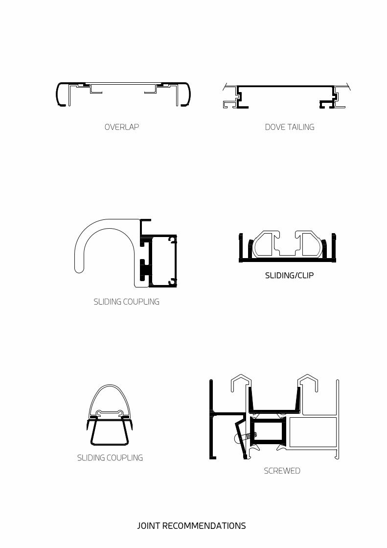
OVERLAP DOVE TAILING
SLIDING/CLIP
SCREWED
SLIDING COUPLING
SLIDING COUPLING
JOINT RECOMMENDATIONS

LIMITED
ROTATION
SLIDING COUPLING
ROTARY
CLIPPING+FASTENING
CLIPPING
IRREMOVABLE
JOINT RECOMMENDATIONS

±0.15
3.2
±0.15
7.2
±0.15
4.2
Min.1.3
±0.15
8.4
±0.15
5.2
±0.15
4
Min.1.3
±0.15
10
.4
±0.15
6.2
±0.15
4.8
Min.1.5
Ca 2
Min.1.5
±0.2
13
.4
±0.15
8.4
±0.2
6
±0.2
16
.5
Ca.2.5
±0.2
7
±0.2
10
.5
Min.1.8
M4 M5 M6
M8 M10
Recommended dimensions for screw pockets that are
designed for screw with dimensions and tolerances
according to SS-ISO 4014/4017, DIN ISO 4014/4017.
SCREW POCKETS RECOMMENDATIONS

±0.2
18
.6
±0.2
12
.5
±0.2
12.2
Ca.3
Min.2.2
±0.25
21.6
Min.2.5
Ca.3.5
±0.2
14
.6
±0.2
14.2
Ca.3.5
Min.2.5
±0.25
24
.6
±0.2
16
.8
±0.3
16.5
Min.3
±0.3
31
±0.3
21
±0.2
19.5
Recommended dimensions for pockets that are
designed for nuts with dimensions and tolerance
according to SS-ISO 4032, DIN ISO 4032
M12 M14
M16 M20
SCREW POCKETS RECOMMENDATIONS

a
0,5a
H
d
D
0
.
1
5
60°
H Treadform acc. NS 1841. (ISO Recommended R 1478-1970)
Treaddepth >2.5 x dia. Wall thickness > 0.3 x dia.
2
4
6
7
8
10
12
14
Screw
No.Dia d H D d a H
2.2
2.9
3.5
3.9
4.2
4.8
5.5
6.3
1.8
2.4
2.8
3.2
3.4
4.0
4.6
5.3
5
7
8.5
9.5
10
11.5
13.5
16
2.2
2.9
3.5
3.9
4.2
4.8
5.5
6.3
1.6
2.2
2.6
2.9
3.0
3.5
4.1
4.8
0.79
1.06
1.27
1.34
1.41
1.59
1.81
1.81
5
7
8.5
9.5
10
11.5
13.5
16
SCREW RECOMMENDATIONS
d
d
D
A
DETAIL A