Embed Size (px)
Citation preview

1
Periferal Devices
Department of Computer Science
Faculty of Civil Engineering, Brno University of Technology
Information Technology 1

2
Global schema
CPU RAM
controlNPeripheraldeviceN
control1Peripheraldevice1
internal bus
I/O bus

3
I/O bus schema – I/O ports
i/O instructions
out A,3F8
in 3F7,B
CPU
I/O ports
controlNPeripheraldeviceN
01001011
10000010
01001111
10101011
00001000
0001
0010
0011
0100
0000
I/O Addr Content
Bi-directionalcommunication
control1Peripheraldevice1
IRQ1
IRQN

4
Input/Output Processing
1. Programmed I/O
• The CPU executes a sequence of instructions, being in direct control of the I/O operations (sensing device status, read/write commands, etc.).
• When the CPU issues a command to the I/O module, it must wait until the I/O operation is complete.
• A lot of wasted time, because the CPU is much faster than devices.
5
Input/Output Processing
2. Interrupt-driven I/O
•IRQ – Interrupt Request
•After issuing an I/O command, the CPU has not to wait until the operation has finished; instead of waiting, the CPU continues with other useful work.
•When the I/O operation has been completed, the I/O module issues an interrupt signal on the bus.
•After receiving the interrupt, the CPU moves the data to/from memory (or I/O ports), and issues a new command if more data has to be read/written.

6
Input/Output Processing
2. Interrupt-driven I/O – cont'd
Advantage over programmed I/O:
• Instead of waiting the operation to be finished, the CPU can do some useful work.
Still a problem:
• If a large amount of data have to be moved, this technique is still not efficient, because the CPU has to take care of each data unit separately, to move it to/from memory.
• Handling the interrupt also takes some time.

7
Input/Output Processing
3. Direct Memory Access (DMA)
• An additional module on the system bus, the DMA module (controller), takes care of the I/O transfer for the whole sequence of data.
• The CPU issues a command to the DMA module and transfers to it all the needed information.
• The DMA module performs all the operations – it transfers all the data between I/O module and memory without going through the CPU.
• When the DMA module has finished, it issues an interrupt to the CPU.

8
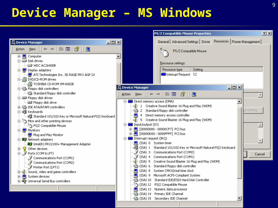
Input/Output Resources
Each controller can occupy some resources:
•I/O ports
•Memory range
•number of IRQ
•DMA channel
9
Device Manager – MS Windows

10
Disk memories
Data structure
After a low-level format, the disk surface is divided it into tracks and sectors.
The tracks are concentric circles around the central spindle on either side of each platter.
Tracks physically above each other on the platters are grouped together into cylinders which are then further subdivided into sectors of 512 bytes apiece.

11
Capacity = NB · NS · NT · NP
NB – bytes per sector (512)
NS – sectors per track
NT – tracks per surface
NP – number of surfaces
Disk capacity
12
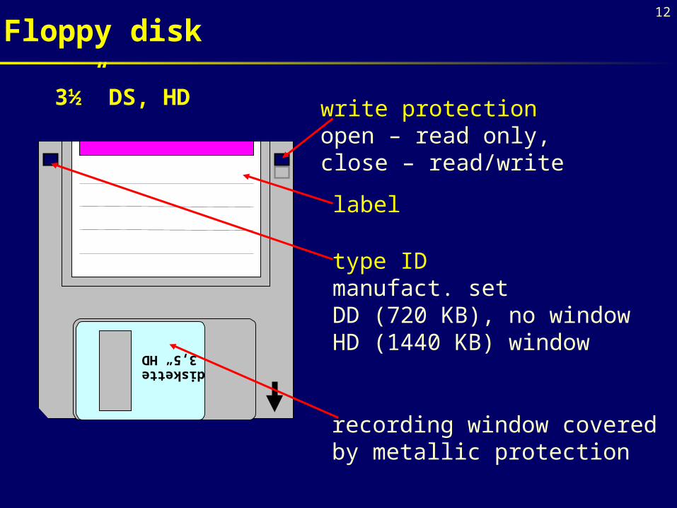
Floppy disk
diskette 3,5“ HD
write protectionopen – read only,close – read/write
label
type IDmanufact. set DD (720 KB), no windowHD (1440 KB) window
recording window coveredby metallic protection
3½” DS, HD
13
•plastic disk coated with thin magnetic layer for storing information
•floppy disks need to be protected against the magnetic field
•before use the formatting process to create the tracks and sectors
•speed of rotation: 300 to 360 rpm
•Floppy Disk Drive – the unit for floppy disk
•FDD controller is integrated direct in mainboard
Floppy disk

14
Floppy disk format
diam surfaces tracks sectors capacity
5¼” 2 40 9 360 KB
5¼” 2 80 15 1 200 KB
3½” 2 80 18 1 440 KB
NB = 512 BNS = 18 sectors per trackNT = 80 tracks per surfaceNP = 2 surfaces
Capacity = NB · NS · NT · NP = 512 · 18 · 80 · 2 =
= 1 474 560 B = 1 440 KB (= 1,44 MB?)

15
Floppy disk classification
• diameter 3½” 5¼” 8”
• number of magnetic surfaces SS (Single Sided) DS (Double Sided)
• density SD (Single Density) DD (Double Density) QD (Quadruple Density) HD (High Density)
Standard today: 3½” DS HD

16
Hard Disk

17
Hard disk

18
Magnetic head

19
Hard disk
• Label HDD (Hard Disk Drive)
• Tracks physically above each other on the platters are grouped together into cylinders
• famous producers:
Western Digital, Seagate, IBM, Quantum, Fujitsu
• HDD controller mainly integrated in the mainboard
Parameters of modern HDs
• capacity – tens GB, access time – few ms (8 ms)
• spin – 5400 to 10000 rpm, transfer rate – tens MB/s
• cache volume – tens MB

20
Hard disk

21
Hard disk interface
• IDE (Integrated Drive Electronics) – most useful EIDE (Enhanced IDE) – transfer rate 16 MB/s Ultra DMA/33 – transfer rate 33 MB/s Ultra DMA/66 – transfer rate 66 MB/s Ultra DMA/100 – transfer rate 100 MB/s
(Seagate uses instead of Ultra DMA label UATA)
• SCSI (Small Computer System Interface)
– more expensive, applicable for servers types: SCSI, Ultra SCSI, Wide SCSI, Ultra Wide SCSI, LVD SCSI (transfer rate 80 MB/s)

22
CD-ROM
• Compact Disc - Read Only Memory
• removable optical storage medium
• standard capacity 650 MB
• Read only
• instead of concentric tracks there is one spiral track of pits from the center of the disc outwards
• the track is divided into the sectors
The pits are typically 0.5 microns wide, 0.83 to 3 microns long and 0.15 microns deep. The space between the tracks - the pitch - is just 1.6 microns. Track density is over 16,000tpi, compared to 96tpi of a floppy disk and the average 400 of a hard disk. Unraveled and laid in a straight line the spiral of data would stretch for four miles.

23
CD-ROM drive
• interface IDE (EIDE, ATAPI) or SCSI
• access time ~ 100 ms
• transfer rate:
1x - 150 KB/s,
2x - 300 KB/s,
24x - 3600 KB/s, …
• func. also for audio CD

24
Printers
Classification according to a physical principle
• dot (matrix)
• ink (bubble)
• laser
• thermal
• others
Parameters of printers
• cost
• density – DPI (Dots Per Inch)
• speed – chars per sec., pages per minute
• costs per page
beat less technology
beat technology(carbon copy allowed)

25
• patterns are created by the series of needle beats, printer head moves above the ribbon
• needles are controlled by electromagnets
• usually 9- a 24-needles per head
• noisy
• quality depends on the ribbon wear
• density 100 - 200 DPI
• low costs
Matrix printers

26
quiet
on stream
electromagnet
paper
printer cylinder
needle
spring
ribbon
center holes
Matrix printers
27
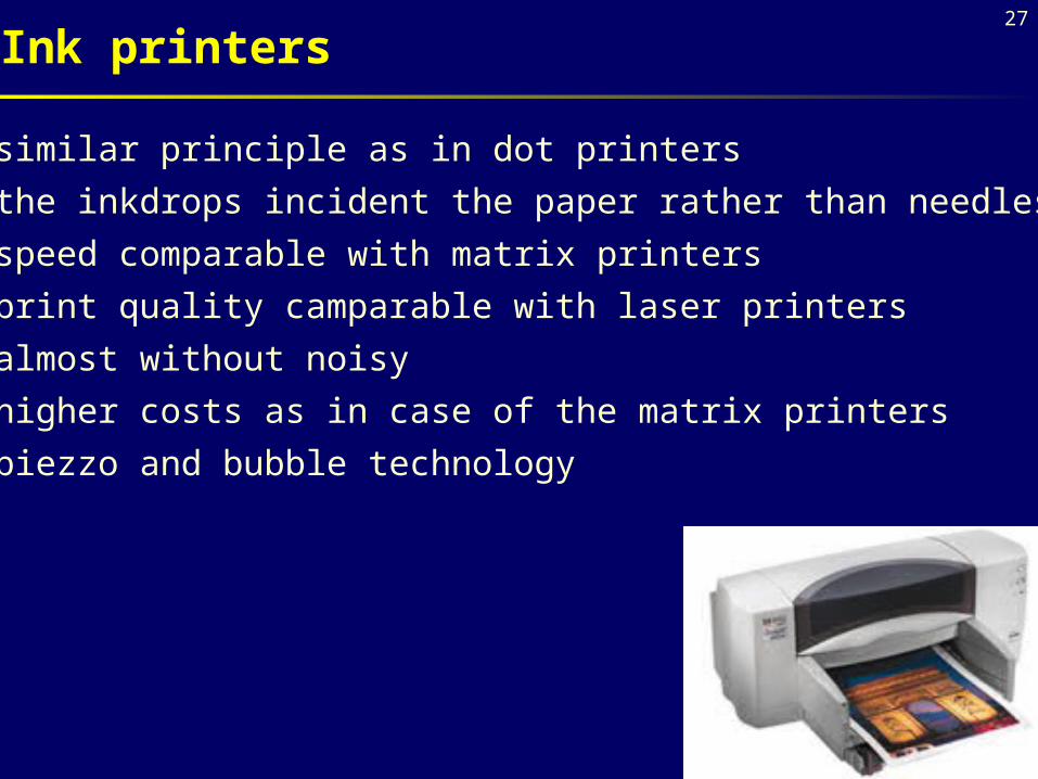
• similar principle as in dot printers
• the inkdrops incident the paper rather than needles
• speed comparable with matrix printers
• print quality camparable with laser printers
• almost without noisy
• higher costs as in case of the matrix printers
• piezzo and bubble technology
Ink printers
28
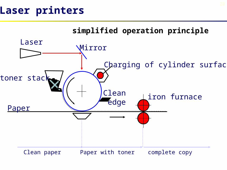
Laser printers
LaserMirror
toner stack
Charging of cylinder surface
Paper
Cleanedge
iron furnace
Clean paper Paper with toner complete copy
simplified operation principle

29
Laser printers
• high quality of printing – resolution 600-1200 DPI,
• high speed – 6 - 40 pages per minute
• without noisy
• high cost
• xerographic paper needed
• during the operation the dangerous ozone is created

30
Principles of color printing
Monitor
• aditive color composition
• model RGB (Red, Green, Blue)
• Red + Green + Blue = White
Printer
• subtractive color composition
• model CMY (Cyan, Magenta, Yellow)
• Cyan + Magenta + Yellow = Black

31
Color model RGB (monitor)
R G
B

32
Color model CMY (printer)
YM
C
33
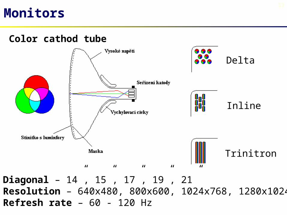
Monitors
Color cathod tube
Delta
Inline
Trinitron
Diagonal – 14”, 15”, 17”, 19”, 21”Resolution – 640x480, 800x600, 1024x768, 1280x1024Refresh rate – 60 - 120 Hz

34
LCD display
Liquid Crystal Display

35
Other peripheral devices
Keyboard
Mouse (classic, optical, wireless)
Joystick
Audiocard
Network adapter
Plotter
Scanner
Streamer
Modem
Virtual reality components

36
• http://www.pctechguide.com
• http://www.howstuffworks.com
• http://www.zive.cz
• White, R.: How computers work. Que, Indianapolis 1999.
• Vrátil, Z.: Postavte si PC. BEN, Praha 1999.
• Horák, J.: Učebnice hardware. Computer Press, Praha 1998.
• Precht, M. – Meier, N. – Kleinlein, J.: EDV-Grundwissen: Eine Einführung in Theorie und Praxis der modernen EDV. Addison-Wesley, 1996.
• Колесниченко, О. – Шишигин, И.: Аппаратные средства РС. «БХВ», Санкт-Петербург 1999.
• Вильховченко, С.: Современный компьютер: устройство, выбор, модернизация. «Питер», Санкт-Петербург 2000.
References