Embed Size (px)
Citation preview

1
Lecture 7
Time: M _ _ _ _14:45 - 17:30
MECH 344/M
Machine Element Design

Contents of today's lecture

• The following are among the factors influencing whether or not threads loosen.
1. The greater the helix angle (i.e., the greater the slope of the inclined plane), the
greater the loosening tendency. Thus, coarse threads tend to loosen more
easily than fine threads.
2. The greater the initial tightening, the greater the frictional force that must be
overcome to initiate loosening.
3. Soft or rough clamping surfaces tend to promote slight plastic flow which
decreases the initial tightening tension and thus promotes loosening.
4. Surface treatments and conditions that tend to increase the friction coefficient
provide increased resistance to loosening.
• The problem of thread loosening has resulted in numerous and ingenious
special designs and design modifications, and it continues to challenge the
engineer to find effective and inexpensive solutions.


• Bolts are typically used to hold parts together against to forces that pull, or slide
• Figure 10.24a shows the general case with external force Fe tending to separate
• Figure 10.24b shows a portion of this assembly as a free body. In this figure the
nut has been tightened, but the external force has not yet been applied.
• The bolt axial load Fb = clamping force Fc = initial tightening force Fi .
• Figure 10.24c shows after Fe has been applied.
• Equilibrium considerations require one or both of the following:
1. an increase in Fb
2. a decrease in Fc .
• The relative
magnitudes of the
changes in Fb and
Fc depend on the
relative elasticities
involved.

• Figure 10.25a shows a plate bolted on a pressure vessel with soft gasket so soft
that the other parts can be considered infinitely rigid in comparison.
• When the nut is tightened to produce initial force Fi, the rubber gasket
compresses; the bolt elongates negligibly.
• Figures 10.25b and 10.25c show details of the bolt and the clamped surfaces.
Note the distance defined as the grip g. On initial tightening, Fb = Fc = Fi .
• Figure 10.25d shows the change in Fb and Fc as separating load Fe is applied.
• The elastic stretch of the bolt caused by Fe is so small. The clamping force Fc
does not diminish and the entire load Fe goes to increasing bolt tension

• Figure 10.26 illustrates the clamped members are “rigid” with precision-ground
mating surfaces and no gasket, The bolt has a center portion made of rubber.
• Here the initial tightening stretches the bolt; it does not significantly compress
the clamped members. (Sealing accomplished by a rubber O-ring).
• Figure 10.26d shows Fe is balanced by reduced Fc without increase in Fb.
• The only way the tension in the rubber bolt can be increased is to increase its
length, and this cannot happen without an external force great enough to
separate physically the mating clamped surfaces. (Note also that as long as the
mating surfaces remain in contact, the sealing of the O-ring is undiminished.)

• The extreme cases can be only approximated.
• In the realistic case in which both the bolt and the clamped members have
applicable stiffness. Joint tightening both elongates the bolt and compresses the
clamped members.
• When Fe is applied, the bolt and clamped members elongate by (g + for both)
• From Figure 10.24 the Fe = increased Fb + the decreased Fc, or
• Where kb and kc are spring constants of bold and clamped material. So substituting
• From figures 10.25 and 10.26

1. When the external load is sufficient to bring the Fc to zero (A), Fb = Fe. So figure
shows Fc = 0 and Fb = Fe for Fe in excess of A.
2. When Fe is alternately dynamic, fluctuations of Fb and Fc can be found from figure

• We need kb and kc. From the basic axial deflection ( = PL/AE) and for spring rate
(k = P/ )
• where the grip g represents the effective length for both. Two difficulties that
commonly arise in estimating kc are
1. The clamped members may consist of a stack of different materials, representing
“springs” in series. For this case,
2. The effective CSA of the clamped members is
not easy to determine. ( irregular shapes, or if
they extend a substantial distance from the bolt
axis) An empirical procedure sometimes used to
estimate Ac is illustrated in Figure.
• One method for estimating the effective area of
clamped members (for calculating kc). Effective
area Ac is approximately equal to the average
area of the dark grey section.

• An effective experimental procedure for determining the ratio of kb and kc for a
given joint is to use a bolt equipped with an electric-resistance strain gage or to
monitor bolt length ultrasonically.
• This permits a direct measurement of Fb both before and after Fe is applied.
• Some handbooks contain rough estimates of the ratio kc/kb for various general
types of gasketed and ungasketed joints.
• For a “typical” ungasketed joint, kc is sometimes taken as 3 kb, but with careful joint
design kc = 6kb.

• The primary loading applied to bolts is tensile, shear, or a combination of the two.
• Some bending is usually present because the clamped surfaces are not exactly
parallel to each other and perpendicular to the bolt axis (Figure 10.29a) and
because the loaded members are somewhat deflected (Figure 10.29b).
• Most times screws and bolts are selected rather arbitrarily. Such is the case with
noncritical applications with small loads
• Almost any size would do, including sizes considerably smaller
than the ones used.
• Selection is a matter of
judgment, based on factors
such as appearance, ease of
handling and assembly, and
cost.
• Even in bolt applications with
known significant loads, larger
bolts than necessary are used
because a smaller size
“doesn’t look right,” and the
cost penalty of using the larger
bolts is minimal.


For ordinary applications Ki can be 0.9


• Bolt fatigue involves fluctuating tension, and some small alternating
bending (as in Figure).
• Alternating shear loads are usually reacted by separate dowel pins.
• Because of initial tightening tension, bolts inherently have high
mean stresses.
• In addition, stress concentration is always present at the thread
roots.
• These two points are treated in Sections 8.9 and 8.11.
• Table 10.6 gives approximate Kf for standard
screws and bolts.
• (1) rolled threads have lower Kf because of work
hardening and residual stresses
• (2) hardened threads have higher Kf because of
their greater notch sensitivity.
• For thread finishes of good commercial quality,
these values may be used with a surface factor CS
of unity.

• We have seen the tendency for most of the bolt load to be carried by the threads
nearest to the loaded face of the nut, and the degree to which the stresses were
concentrated in this region was influenced by the nut design.
• This is one reason why actual values of Kf may differ from those given in Table
10.6.

• Fatigue strength of a
steel M10 * 1.5 bolt
class 8.8 installed in a
joint with kc = 2kb, and
subjected to an external
load which fluctuates
between 0 and 9 kN.
• Curves correspond to Fi
10 kN.
• Each time Fe is applied,
Fb increases and Fc
decreases, with the sum
of the two effects being
equal to Feof 9 kN.
• When Fe is removed, Fb
and Fc revert to their
initial value of 10 kN.

• Fatigue strength of a
steel M10 * 1.5 bolt
class 8.8 installed in a
joint with kc = 2kb, and
subjected to an external
load which fluctuates
between 0 and 9 kN.
• In case 2, curves are for
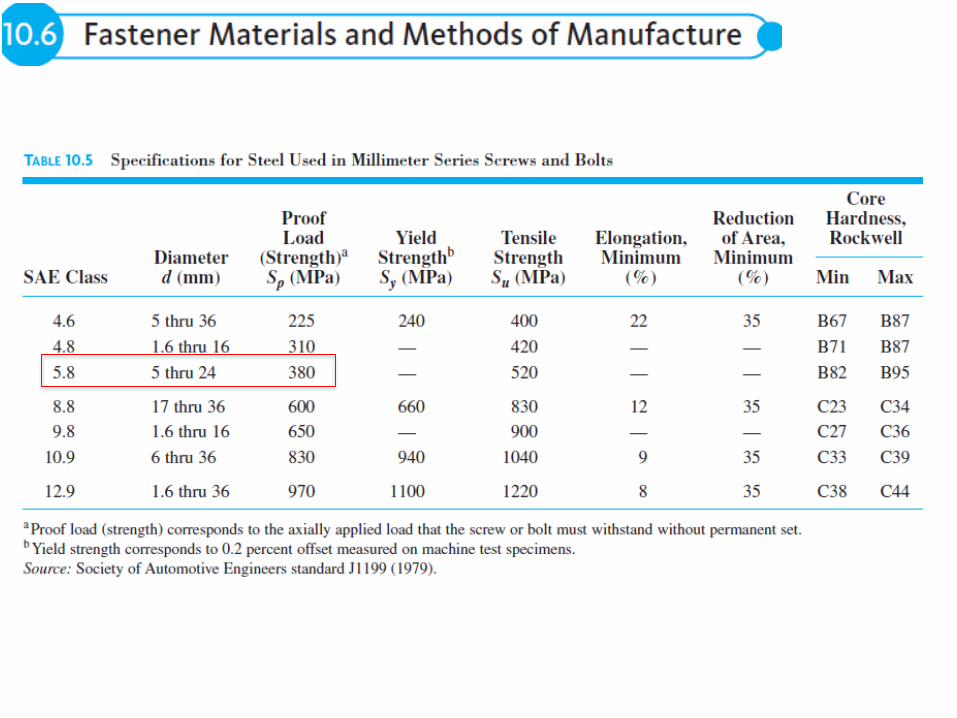
Fi = SyAt = 660 * 58.0 =
38.3 kN) (table 10.2 & 5)
• With the Fi = yield
strength, the bolt CSA of
At is stressed to Sy, first
application of Fe does not
increase Fb as no
elongation possible.
• So all of it is reacted by
decrease in Fc


• When Fe is released, bolt
relaxes slightly, and this
relaxation is elastic.
• Hence, changes in Fb & Fc
are controlled by kb & kc .
• Elastic bolt relaxation is
reversible, and the load can
be reapplied without
yielding. As Fe cycles, Fb &
Fc fluctuate.
• Stress on the case 1 is
517MPa for 10KN and
672MPa for 13KN. Since
yielding happens at 660, the
max stress stays at 660.
• When the Fb comes back to
10KN the elastic difference
is 155KN (672-517)


• In both cases the max corresponds to Sy and the min results from an elastic
relaxation during the removal of load, represented by the same point 2 on Fig
• The difference in case 2 is greater yielding due to higher Fi, Point 2 applies to
any Fi between 10 and 38.3 kN. If Fi>12.8 kN, the thread root stress reaches
point 1 upon initial tightening.
• Point 3 shows the thread root stress after Fe removal. The difference between
points 1 and 3 is caused by bolt yielding during the initial application of Fe.
• When Fe added the point
moves from 3 back to 2.
• The SF wrt fatigue failure is
139/73 = 1.9, as overload to
failure would be point 4 or 139
MPa (alt)
• It is an Fe fluctuation between
zero and 1.9 times 9 kN, or
17.1 kN.

• Tightening bolts to full yield strength should not be specified, it is desirable to
specify tightening to the full proof strength (i.e., Fi = SpAt)
• The advantages of bolt tightening this tightly are
1. The dynamic load on the bolt is reduced because the effective area of the
clamped members is larger. (The greater the initial tightening, the more
intimately in contact the clamped surfaces remain during load cycling,
particularly when considering the effect of load eccentricity
2. There is maximum protection against overloads which cause joint separation
3. There is maximum protection against thread loosening
• It is important to recognize that the small amount of thread root yielding that
occurs when bolts are tightened to the full proof load is not harmful to any bolt
material of acceptable ductility.
• Note, for example, that all the steels listed in Tables 10.4 and 10.5 have an area
reduction of about 35 %.


1. Modify stiffnesses to decrease the portion of the Fe that increases Fb .
a. Increase Kc by using higher E materials, flat and smooth mating surfaces
(without gaskets), & greater area and thickness of plates in compression.
b. Decrease Kb by securing the desired clamping force with smaller bolts of
greater strength and by fully utilizing the material strength through more
precise control of initial tensioning.
2. Modify the nut (female threaded member) to equalize the load carried by
several contact threads, and make sure # of threads in contact is adequate.
3. Reduce the thread root stress concentration by using a larger root radius.
a. MIL-B-7838, calls for modifying the basic profile of the external
thread by using a 0.144p thread root fillet radius for tension bolts up to
180-ksi tensile strength.
b. Standard MIL-S-8879 specifies a fillet radius of 0.180p, for bolts of
180-ksi tensile strength and higher.
c. Exotic aerospace bolts of columbium, tantalum, beryllium, and other
highly notch-sensitive materials sometimes use fillet radii of 0.224p

4. Use a material of highest practical proof strength in order to obtain maximum
initial tension.
5. Use tightening procedures that ensure values of Fi as close as possible to AtSp.
6. Be sure that the threads are rolled rather than cut and that threads are rolled
after heat treatment. The greater the strength, the more important it is to roll
after hardening. This has been experimentally verified for tensile strengths as
high as 300 ksi.
7. After reducing stress concentration and strengthening the thread as much as
possible, be sure that the fillet radius under the bolt head is sufficient to avoid
failures at this point. Cold-roll this fillet if necessary.
8. Minimize bolt bending.
9. Guard against partial loss of initial tension in service because threads loosen or
materials take a permanent set. Retighten bolts as necessary. Also take steps to
ensure proper tightening when bolts are replaced after being removed for
servicing, and to replace bolts before they yield heavily due to repeated
retightening.


• Springs are elastic members that exert forces, or torques, and
absorb energy, which is usually stored and later released.
• Mostly made of metal. Plastics, and rubber are used when loads
are light
• For applications requiring compact springs providing very large
forces with small deflections, hydraulic springs have proved
effective.
• If energy absorption with maximum
efficiency (minimum spring mass) is the
objective, the ideal solution is an
unnotched tensile bar,
• Unfortunately, tensile bars of any
reasonable length are too stiff for most
spring applications; hence it is necessary
to form the spring material so that it can
be loaded in torsion or bending.

• Simplest spring is the torsion bar spring
• Used in automotive applications
• Stress, angular deflection and spring rate
• For a solid bar of diameter ‘d’
• Shear modulus G is

• Figure shows compression and extension springs of small helix angle
• Force F applied along helix axis, and on the whole length the wire experiences F
(transverse force) and FD/2 (torsion force)
• For spring of solid wire with dia ‘d’