Embed Size (px)
Citation preview
1
Friction in Journal bearings
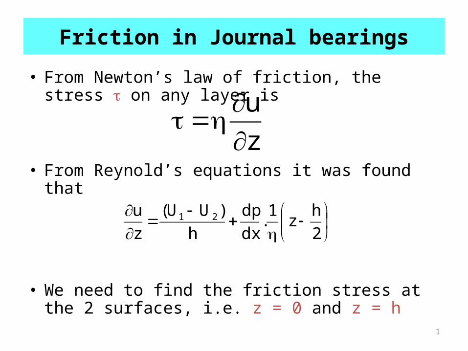
• From Newton’s law of friction, the stress on any layer is
• From Reynold’s equations it was found that
• We need to find the friction stress at the 2 surfaces, i.e. z = 0 and z = h
z
u
2
hz
1.
dx
dp
h
)UU(
z
u 21
2
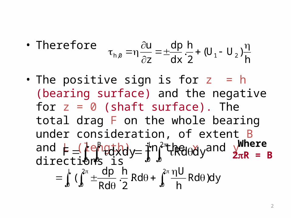
• Therefore
• The positive sign is for z = h (bearing surface) and the negative for z = 0 (shaft surface). The total drag F on the whole bearing under consideration, of extent B and L (length), in the x and y directions is
h)UU(
2
h.
dx
dp
z
u210,h
dyRddxdyFL
0
B
0
L
0
2
0
L
0
2
0
2
0dy)Rd
h
URd.
2
h.
Rd
dp(
Where 2R = B

3
• Now h = c(1+cos) and dh/d= -csin, so integrating the first term by parts gives
• The first of these terms is zero, as p must be zero at = 0, and 2 (Sommerfeld’s condition)
• For the second term the integral is solved using the relation
L
0
2
0
2
0
2
0
dy)cos1(c
URddsinc
2
p
2
phF
L
0
2
0sinWdysinpRd

4
• The third term should be taken under two separate conditons. This is because the viscosity is not constant around the whole circumference. If there is cavitation in some part of the bearing a different law will apply.
• At the moment the bearing will be assumed to be full of a liquid with one single viscosity. Thus, using Sommerfeld’s substitution
• The expression for friction then becomes
L
0
2
0
2
0 2
2/12
d)cos1)(1(
)1)(cos1(
c
URL
)cos1(
d
c
UR
2/122
0
2/12 )1(c
URL2
d)1(c
URL
2/120,h )1(c
URL2sin
R2
WcF
The positive sign in front of the first term is when z = h (at the bearing surface), and the negative sign when z = 0 (at the shaft surface)
5
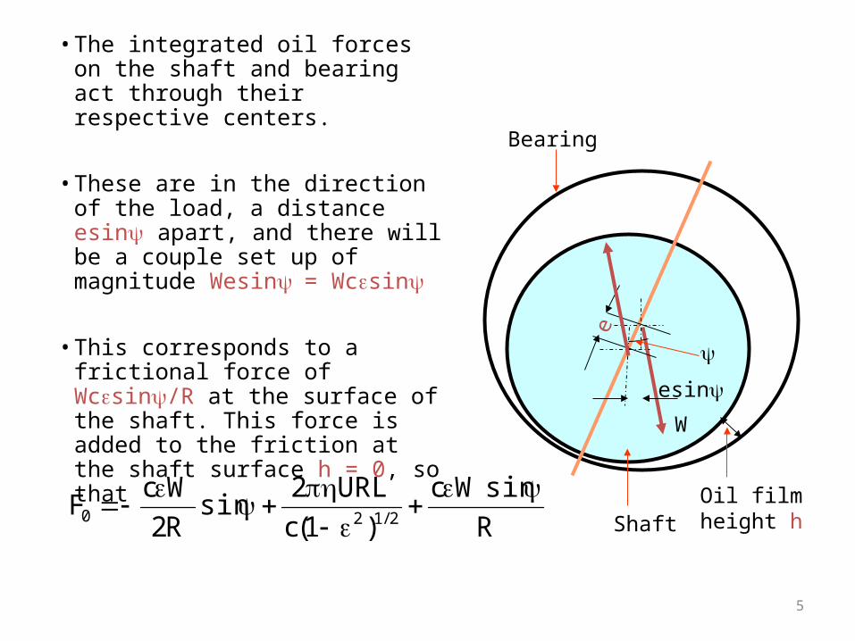
• The integrated oil forces on the shaft and bearing act through their respective centers.
• These are in the direction of the load, a distance esin apart, and there will be a couple set up of magnitude Wesin= Wcsin
• This corresponds to a frictional force of Wcsin/R at the surface of the shaft. This force is added to the friction at the shaft surface h = 0, so that
W
e
esin
R
sinWc
)1(c
URL2sin
R2
WcF
2/120
Shaft
Bearing
Oil film height h

6
This is exactly equal to the friction Fh, when z = h. Therefore
for both surfaces. Of these two terms, the first arises from the offset between the center of the shaft and that of the bearing. The second is the simple Newtonian friction. •Petroff analysis of friction gives friction as
•The term 1/(1-2)1/2 is a multiplier to take into account the eccentric running of the shaft
2/120,h )1(c
URL2sin
R2
WcF
c
URL2area.
c
UF
7
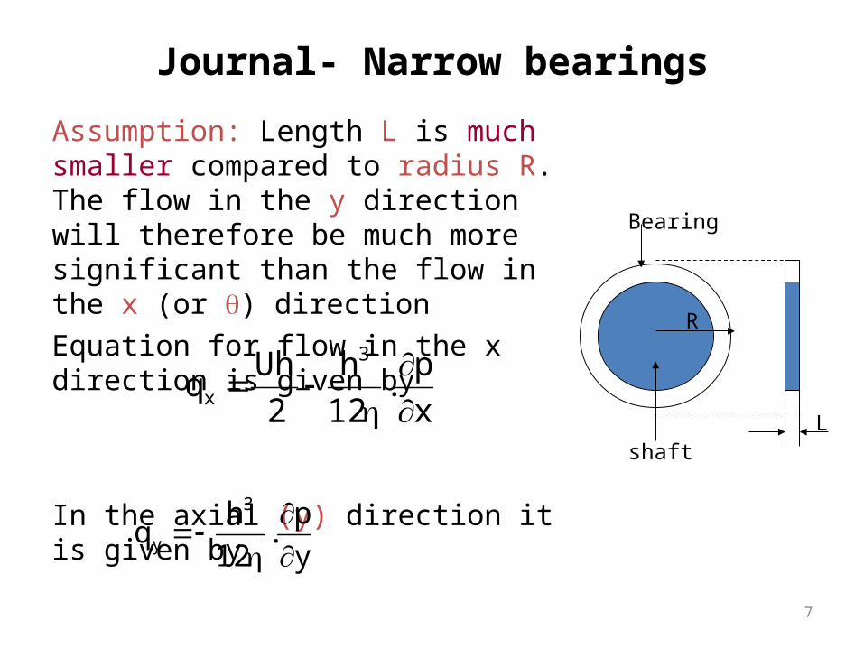
Journal- Narrow bearings
Assumption: Length L is much smaller compared to radius R. The flow in the y direction will therefore be much more significant than the flow in the x (or ) directionEquation for flow in the x direction is given by
In the axial (y) direction it is given by
x
p.
12
h
2
Uhq
3
x
shaft
Bearing
L
R
y
p.
12
hq
3
y

8
The continuity equation is
If the average pressure in the lubricant is p, then is of the order of pressure/circumference or p/2R and is of the order pressure/length or p/L.
• As R>>L , << as x = R and L is in the y direction
Furthermore, the term in qx is also taken to be much
small compared to Uh/2
0y
q
x
q yx
x
p
x
p
x
p
y
p

9
Pressure change with y
• Thus the continuity equation reads
• Now h varies with x only (assuming no tilt in the shaft). Therefore the equation can be written as
Or
0y
p.
12
h
y2
Uh
x
3
dx
dh.
2
U
dy
pd.
12
h2
23
dx
dh.
h
U6
dy
pd32
2
10
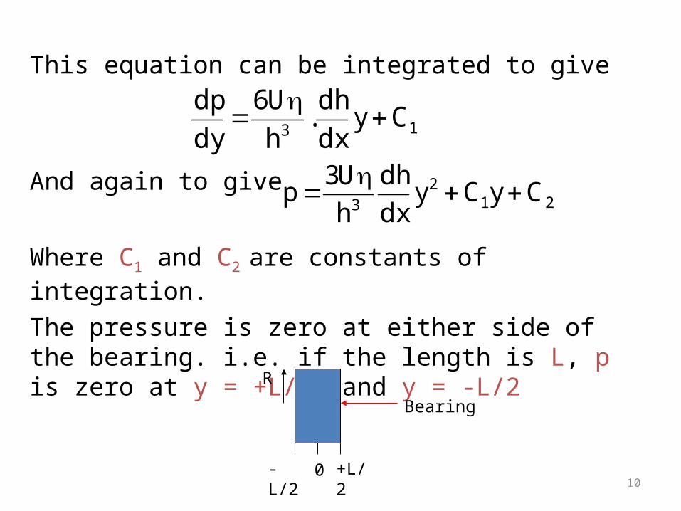
This equation can be integrated to give
And again to give
Where C1 and C2 are constants of integration.
The pressure is zero at either side of the bearing. i.e. if the length is L, p is zero at y = +L/2, and y = -L/2
13Cy
dx
dh.
h
U6
dy
dp
212
3CyCy
dx
dh
h
U3p
-L/2 +L/20
Bearing
R

11
Due to symmetry dp/dy must be zero on the center line (y=0). Therefore C1 = 0 as dp/dy = 0, at y = 0
From the former condition C2 must equal
Hence we get the pressure as
Now h = c(1 + cos) and x = Rtherefore
4
L
dx
dh.
h
U3 2
3
dx
dh
4
Ly
h
U3p
22
3
)sin(cd
dh
12
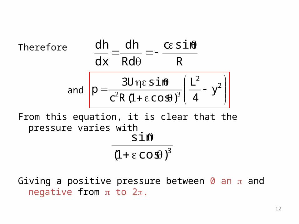
Therefore
and
From this equation, it is clear that the pressure varies with
Giving a positive pressure between 0 an and negative from to 2.
R
sinc
Rd
dh
dx
dh
22
32y
4
L
)cos1(Rc
sinU3p
3)cos1(
sin
13
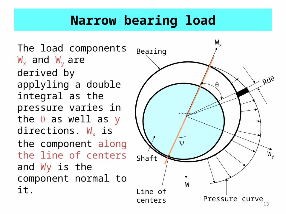
Narrow bearing load
The load components Wx and Wy are derived by applyling a double integral as the pressure varies in the as well as y directions. Wx is the component along the line of centers and Wy is the component normal to it.
Rd
Pressure curve
Wx
Wy
WLine of centers
Bearing
Shaft
14
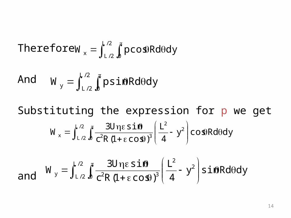
Therefore
And
Substituting the expression for p we get
and
2/L
2/L 0y dyRdsinpW
2/L
2/L 0x dyRdcospW
2/L
2/L 0
22
32x dyRdcosy4
L
)cos1(Rc
sinU3W
2/L
2/L 0
22
32y dyRdsiny4
L
)cos1(Rc
sinU3W
15
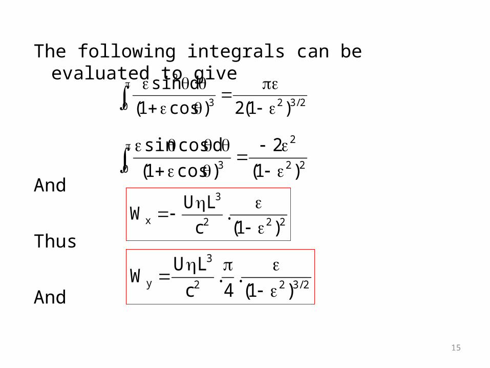
The following integrals can be evaluated to give
And
Thus
And
0 2/323
2
)1(2)cos1(
dsin
0 22
2
3 )1(
2
)cos1(
dcossin
2/322
3
y )1(.
4.
c
LUW
222
3
x )1(.
c
LUW
16
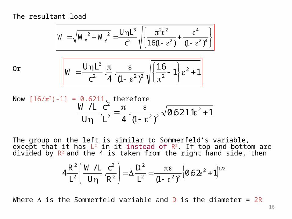
The resultant load
Or
Now [16/2)-1] = 0.6211, therefore
The group on the left is similar to Sommerfeld’s variable, except that it has L2 in it instead of R2. If top and bottom are divided by R2 and the 4 is taken from the right hand side, then
Where is the Sommerfeld variable and D is the diameter = 2R
42
4
2
22
2
32
y2
x )1()1(16c
LUWWW
1.116
)1(.
4.
c
LUW 2
2222
3
1.6211.0)1(
.4L
c.
U
L/W 2222
2
2/12222
2
2
2
2
2
162.0)1(L
D
R
c.
U
L/W
L
R4
17
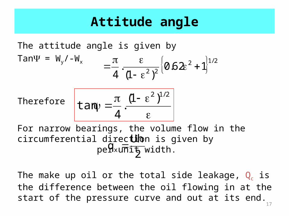
Attitude angle
The attitude angle is given byTan= Wy/-Wx
Therefore
For narrow bearings, the volume flow in the circumferential direction is given by per unit width.
The make up oil or the total side leakage, Qc is the difference between the oil flowing in at the start of the pressure curve and out at its end.
2/1222
162.0)1(
.4
2/12 )1(
.4
tan
2
Uhqx
18
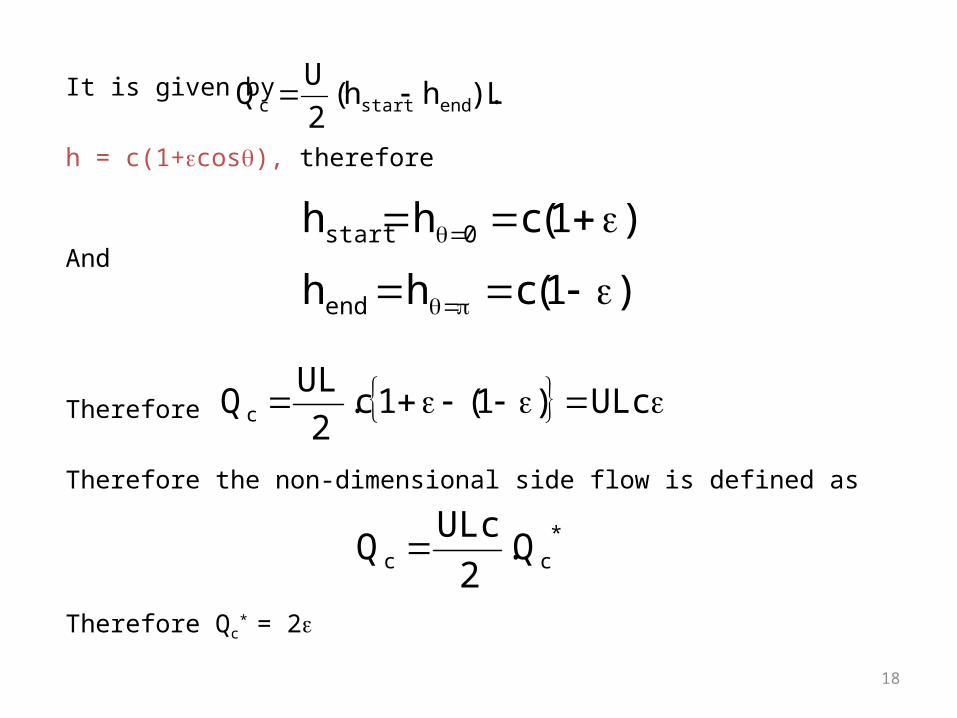
It is given by
h = c(1+cos), therefore
And
Therefore
Therefore the non-dimensional side flow is defined as
Therefore Qc* = 2
L).hh(2
UQ endstartc
)1(chh 0start
)1(chhend
ULc)1(1c.2
ULQc
*cc Q.
2
ULcQ

19
Detergent additives
• To clean undesired substances (mostly oxidation products and contaminants) from the surfaces and passages of a lubricating system
• Detergent additives are soaps of high molecular weight, soluble in oil
• Consist of a metal and organic component
• Ashless (without metal) detergents are also employed leaving no metallic residue

20
Detergent additives
• Make the binding agents in deposits less effective• Particles remain in suspension and can be drained or filtered off• Envelope the deposit particles and prevent them from agglomerating with
other particles• E.g. metal phosphonates, sulphonates
Binding agent
Deposit particles that agglomerate due to binding agent
Detergent
DetergentDetergent bound to binding agent
Particles remain free
Detergent DetergentOR Envelope the particles, preventing them from forming deposits
21
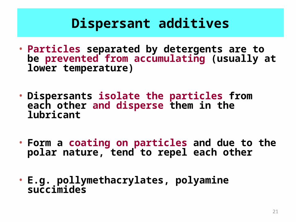
Dispersant additives
• Particles separated by detergents are to be prevented from accumulating (usually at lower temperature)
• Dispersants isolate the particles from each other and disperse them in the lubricant
• Form a coating on particles and due to the polar nature, tend to repel each other
• E.g. pollymethacrylates, polyamine succimides

22
Detergent
Dispersants- mechanism
Separated and suspended particles due to detergent action
Detergent Detergent
Dispersant particles
(same charge on outside)
+ +
+ +
Like charges repel, hence there is dispersion
Detergent

23
Pour point depressants
• Pour point is the lowest temperature at which the lubricant will flow
• Forms waxy crystals at lower temperatures
• Pour point depressants reduce the pour point and are therefore required when operating at lower temperatures
• E.g. methacrylate polymers, polyalkylphenol esters
24
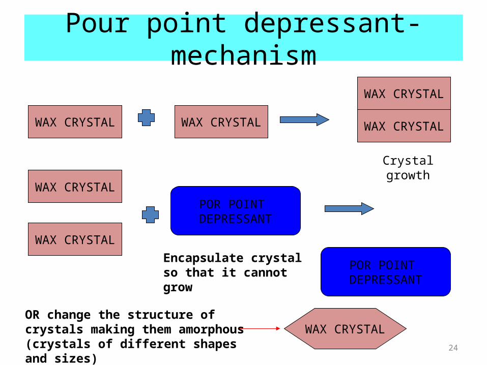
Pour point depressant- mechanism
WAX CRYSTAL WAX CRYSTAL
WAX CRYSTAL
WAX CRYSTAL
Crystal growth
WAX CRYSTAL
WAX CRYSTALPOR POINT
DEPRESSANT
WAX CRYSTALPOR POINT
DEPRESSANT
Encapsulate crystal so that it cannot grow
WAX CRYSTALOR change the structure of crystals making them amorphous (crystals of different shapes and sizes)

Viscosity index improvement
• Remove aromatics (low VI) during refining stage
• Blending with high viscous oil
• Using polymeric additives that cause an increase in viscosity with temperature due to chain unwinding
• E.g. polyisobutenes, ethylene/propylene copolymers,

VI improvement using polymeric additives
Temperature increase
Polymer chains
•As the temperature increases, the polymer chains tend to uncoil.
•In the uncoiled form, they tend to increase the viscosity thereby compensating for the decrease in viscosity of the oil

Boundary and extreme pressure additives
• Reduce friction, control wear, and protect surfaces from severe damage
• Used in highly stressed machinery where there is metal to metal contact leading to boundary lubrication
• Chemically react with sliding metal surfaces to form films which are insoluble in the lubricant
• Have low shear strength than the metal
• These layers are more easily sheared in preference to the metal
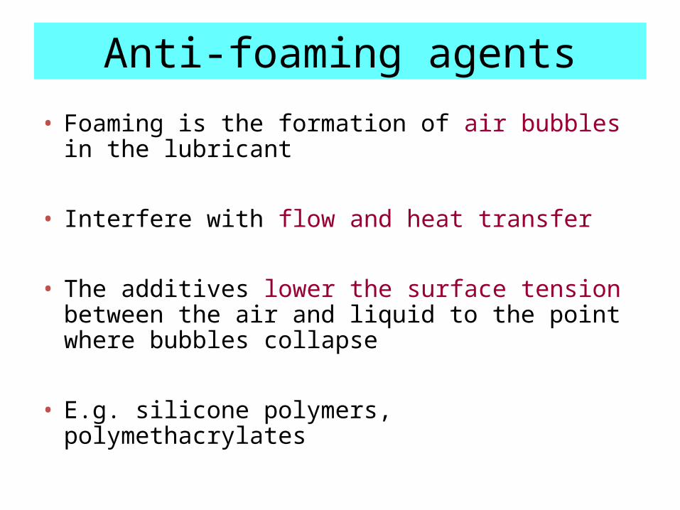
Anti-foaming agents
• Foaming is the formation of air bubbles in the lubricant
• Interfere with flow and heat transfer
• The additives lower the surface tension between the air and liquid to the point where bubbles collapse
• E.g. silicone polymers, polymethacrylates

Friction modifiers• In boundary lubrication there is poor film strength, there is
surface to surface contact
• These modifiers are polar materials such as fatty oils, acids and esters having long chains
• Form an adsorbed film on the metal surfaces with the polar ends projecting like carpet fibers
• Provide a cushioning effect and keep metal surfaces apart from each other