Embed Size (px)
Citation preview

Revit 1
LECTURE NOTES: CLASS 10
© 2010 Xone Consulting Ltd. Page 1 of 19
AGENDA:
1. Editing Wall Profiles
2. Joining and Cutting Geometry
3. Adding Wall Openings
4. Hosted Sweeps for Walls and Roofs
1. Editing Wall Profiles
Revit allows you to customize the shape of a wall by editing the profile. This lets you sketch
curved or even circular wall objects and fine-tune the shape of a wall to accommodate steps,
jogs, or angled edges anywhere around its perimeter.
If you select a wall and choose Edit Profile from the Ribbon, you will be placed in Sketch mode
and the existing wall shape will be displayed as a rectangular sketch.
When you edit the profile of a
wall, any attachments to the
top or the base of the wall will
be removed while you edit
the profile. When you finish
the sketch, depending on the
edits you have made, the
previous attachments may be
permanently discarded.
To revert a sketched wall
profile to its original shape,
pick the wall and from the
Options Bar, choose Remove
Sketch.

Revit 1
LECTURE NOTES: CLASS 10
© 2010 Xone Consulting Ltd. Page 2 of 19
Editing a wall profile is best
done in an elevation view. If
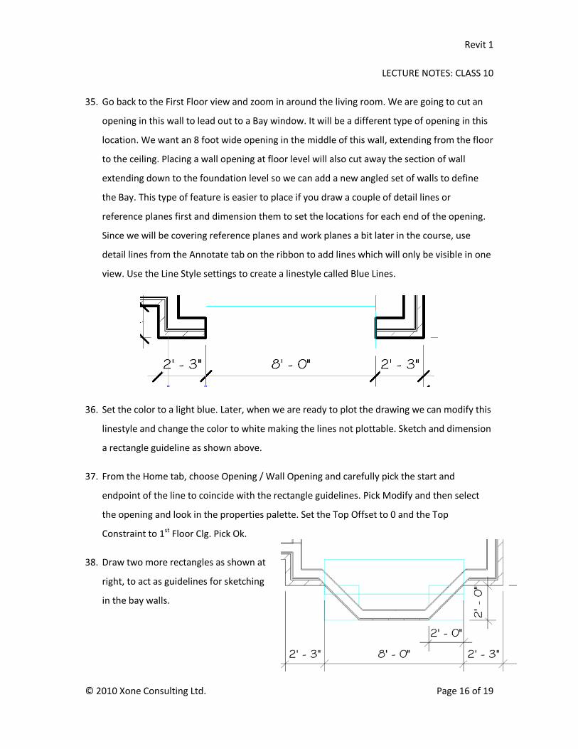
you start the process in a 3D
view when you select the
wall, switch to the
appropriate elevation view
to perform the edit. If you
select a wall in a plan view
and choose the Edit Profile
option, a Go to View dialog
will appear allowing you to
choose an appropriate view
in which you will be able to
edit the sketch. In the
example shown here, since the
selected wall is on the South side
of the building, I would choose
the South Elevation as the best
choice to display the most
complete context.
Wall shape handles appear at the
default top and bottom
elevations for a wall. Selecting
the shape handle allows you to
drag the top or bottom of the
wall up or down, dynamically
modifying the height or base
elevation offset.
Revit 1
LECTURE NOTES: CLASS 10
© 2010 Xone Consulting Ltd. Page 3 of 19
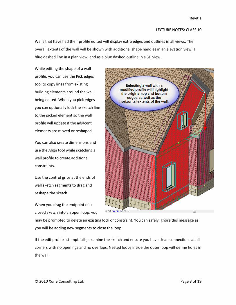
Walls that have had their profile edited will display extra edges and outlines in all views. The
overall extents of the wall will be shown with additional shape handles in an elevation view, a
blue dashed line in a plan view, and as a blue dashed outline in a 3D view.
While editing the shape of a wall
profile, you can use the Pick edges
tool to copy lines from existing
building elements around the wall
being edited. When you pick edges
you can optionally lock the sketch line
to the picked element so the wall
profile will update if the adjacent
elements are moved or reshaped.
You can also create dimensions and
use the Align tool while sketching a
wall profile to create additional
constraints.
Use the control grips at the ends of
wall sketch segments to drag and
reshape the sketch.
When you drag the endpoint of a
closed sketch into an open loop, you
may be prompted to delete an existing lock or constraint. You can safely ignore this message as
you will be adding new segments to close the loop.
If the edit profile attempt fails, examine the sketch and ensure you have clean connections at all
corners with no openings and no overlaps. Nested loops inside the outer loop will define holes in
the wall.

Revit 1
LECTURE NOTES: CLASS 10
© 2010 Xone Consulting Ltd. Page 4 of 19
2.Joining and Cutting Geometry
The Join Geometry tool lets you create a clean connection between 2 or more host elements that
share a common face. This tool also allows you to join hosts and in-place families. You can also
use the Cut tool, which although primarily intended for use with modeling geometry in the
Family Editor, may also be used to embed one wall in another.
Joining Geometry in the Family Editor environment will create a union between two different
shapes or volumes. In a regular project environment, one of the joined elements will cut the
other volume, removing the overlapping portion.
When you join geometry in a project, floors, ceilings and roofs will always cut walls. Walls will
cut columns and structural elements will cut host elements such as walls, roofs, etc. When you
join two walls, the order that you select the elements will determine which will be cut by the
other. The first object that you pick is going to stay the same and cut a hole in the second
selection. In the image above, if I want the brick component to cut away the bottom of the frame
wall where it is showing through the brick, I will pick the main brick wall first. If I join the wall to
the roof, the overlapping lines at the sectioned area will be removed with the roof cutting the
wall regardless of the selection order.

Revit 1
LECTURE NOTES: CLASS 10
© 2010 Xone Consulting Ltd. Page 5 of 19
3. Wall Openings
Openings may be created in walls a number of different ways. Doors and Windows, of course,
cut openings in walls automatically. They will be moved along with their host element and will
be deleted automatically if the door or window is removed.
To create openings such as interior arches or cased openings that do not include doors, you can
insert a special type of component family defined with a void extrusion and typically called
Opening_Shape.
Various opening families are available to define standard flat openings, with or without trim
elements included. The complexity of the opening is dependent on the component family.
Duplicate an opening and set the dimension and shape parameters included with that family to
create any required size or variation that the family parameters support.
Component openings usually include plan view symbolic lines as are typically depicted on
architectural drawings. Openings in walls usually show the outline of the opening with hidden
lines to indicate the overhead edges.

Revit 1
LECTURE NOTES: CLASS 10
© 2010 Xone Consulting Ltd. Page 6 of 19
A second way to
create openings in a
wall is to use the
Opening tool on the
Home tab of the
Ribbon. This is the
same tool that is
used to create
Dormers. When you
select the Wall
Opening tool you
specify the start and end point of the opening. It may be drawn in an elevation view where you
can see the scope of the opening or in a plan view where you can choose the start and end point
of the opening and then specify the top and bottom locations via the element properties dialog
box.
To lock a wall
opening’s size or
position in the wall,
add dimensions and
lock them.
You can create detail
lines or reference
planes to assist in
positioning the
opening if desired.
To create non-
rectangular openings in a wall, edit the Wall Profile and draw closed shapes inside the outer
perimeter. Any closed, nested loop will produce a hole in the wall.

Revit 1
LECTURE NOTES: CLASS 10
© 2010 Xone Consulting Ltd. Page 7 of 19
4. Hosted Sweeps for Walls and Roofs
A sweep is a tool for creating an extruded shape that will follow a path. Sweeps may be created
with the Family Editor, as In-place families or by using the Hosted Sweep tool from within a
Project. Sweeps added to a wall with the Hosted Sweep method can be selected independently
of the wall and can be repositioned or modified.
Sweeps may also be defined as a constant feature for an element such as a wall by adding the
sweep through editing the assembly of the wall type and opening the Wall Sweeps dialog where
you can select a profile, set its material, its location and orientation, and how it reacts to walls
and inserts when it intersects them.
Wall sweeps may be set to Cut Walls (recommended) and optionally to be cuttable by inserts
such as doors and openings. If a sweep is cuttable, a window frame that intersects the sweep will
cut a portion of the sweep away and it is not possible to force the sweep through the insert. If a
sweep is not cuttable it will still stop at openings but a control grip will be added to each end of
the sweep allowing you to drag it and reposition the end.
Revit 1
LECTURE NOTES: CLASS 10
© 2010 Xone Consulting Ltd. Page 8 of 19
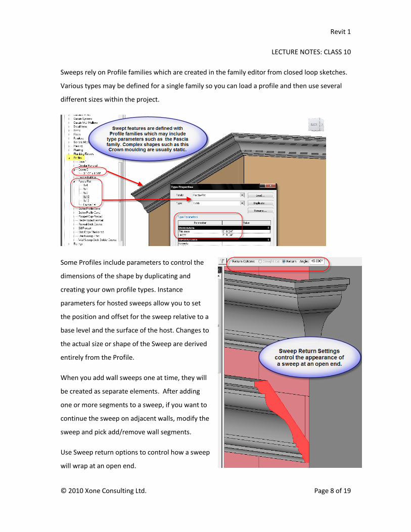
Sweeps rely on Profile families which are created in the family editor from closed loop sketches.
Various types may be defined for a single family so you can load a profile and then use several
different sizes within the project.
Some Profiles include parameters to control the
dimensions of the shape by duplicating and
creating your own profile types. Instance
parameters for hosted sweeps allow you to set
the position and offset for the sweep relative to a
base level and the surface of the host. Changes to
the actual size or shape of the Sweep are derived
entirely from the Profile.
When you add wall sweeps one at time, they will
be created as separate elements. After adding
one or more segments to a sweep, if you want to
continue the sweep on adjacent walls, modify the
sweep and pick add/remove wall segments.
Use Sweep return options to control how a sweep
will wrap at an open end.
Revit 1
LECTURE NOTES: CLASS 10
© 2010 Xone Consulting Ltd. Page 9 of 19
Wall Reveals are very similar in function and application to Wall Sweeps, but instead of using a
profile to add a built up section to the wall, a Reveal uses a profile to remove or cut away a
portion of the wall. Reveals are typically created with rectangular profiles using sizes of brick
multiples such as 2 courses, rowlock course, or soldier course.
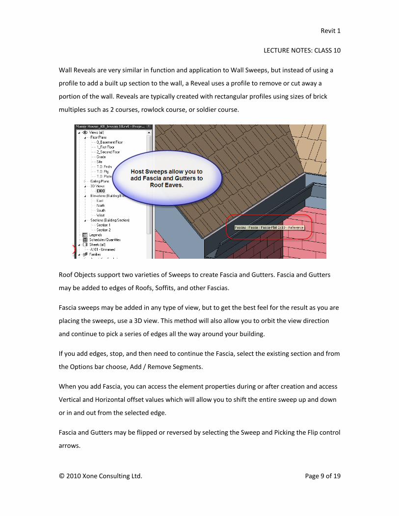
Roof Objects support two varieties of Sweeps to create Fascia and Gutters. Fascia and Gutters
may be added to edges of Roofs, Soffits, and other Fascias.
Fascia sweeps may be added in any type of view, but to get the best feel for the result as you are
placing the sweeps, use a 3D view. This method will also allow you to orbit the view direction
and continue to pick a series of edges all the way around your building.
If you add edges, stop, and then need to continue the Fascia, select the existing section and from
the Options bar choose, Add / Remove Segments.
When you add Fascia, you can access the element properties during or after creation and access
Vertical and Horizontal offset values which will allow you to shift the entire sweep up and down
or in and out from the selected edge.
Fascia and Gutters may be flipped or reversed by selecting the Sweep and Picking the Flip control
arrows.
Revit 1
LECTURE NOTES: CLASS 10
© 2010 Xone Consulting Ltd. Page 10 of 19
Exercise Notes
In the following exercise you will continue to develop the Manor House project, editing the wall
profiles where they meet the roof, adding wall openings and a Bay window projection, modifying
wall types to include wall sweeps, and wall extensions, and joining geometry to create clean
connections between overlapping elements. Finally, you will add Fascia and Gutter host sweeps
to the roof edges.
1. Open the Manor project and set the 3D view current. At this point we have added both
dormers and dormer openings to the roof over the den and finished laying out the interior
walls for the guest suite. Let’s look at how to get a better view of our developing model.
2. Select the roof and from the View Control bar, choose Hide element so you can look down
into the space. A floor would help but that will come in the next lesson. For now, orbit the
view and try looking into the rooms from different angles. Reset the temporary visibility.
3. Pick the roof and from the Temporary Hide/Isolate tool, choose Isolate Element. Examine
the roof from various angles and check your dormer openings to see how they cut through
the walls and roof. Switch to the Second Floor view and zoom in over the garage.
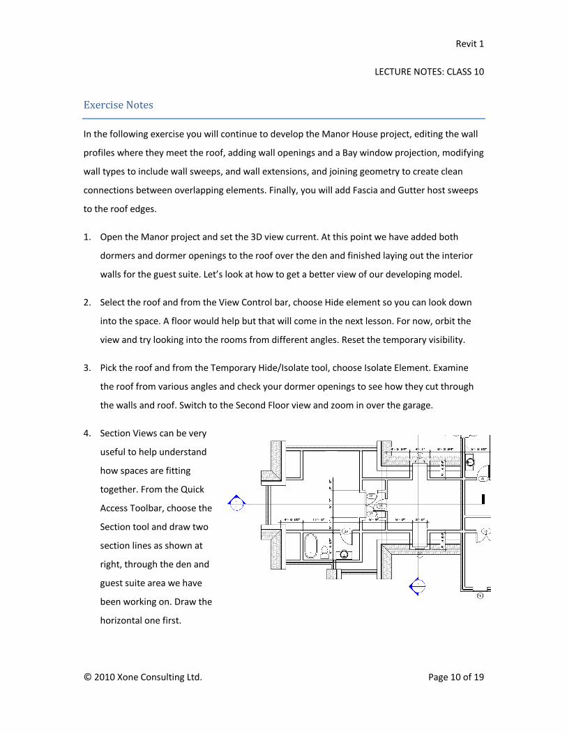
4. Section Views can be very
useful to help understand
how spaces are fitting
together. From the Quick
Access Toolbar, choose the
Section tool and draw two
section lines as shown at
right, through the den and
guest suite area we have
been working on. Draw the
horizontal one first.

Revit 1
LECTURE NOTES: CLASS 10
© 2010 Xone Consulting Ltd. Page 11 of 19
5. Float your cursor over the blue section head for the horizontal section line and when it
highlights, double-click to go to the section view. Type SD to shad the display. Turn the
Shadow display on just for fun. If your computer starts to slow down, disable shadows. Pick
the two dormer roofs and set their Base Offset to -1'-6".
6. Switch back to the Second floor view. Pick the section line and use the Flip arrows to reverse
the direction so it is looking toward the front of the building. Double-click the section head
again to switch to the new section view to the South. In this view you should see the second
section line cutting through a dormer and extending above the roof. Double click the section
head on this section line to switch to its linked view. Shade the view and optionally turn on
shadows to see how they enhance the sense of depth in the section.
7. Switch back to the second floor view again. Select the section line through the dormer and
reduce its extents as shown. Double-click the
Section head to switch to the section view.
8. In the section view you can easily
see the opening where our dormer
wall does not fill the gap to the
main roof. One solution is to edit the wall profile to cover the hole.

Revit 1
LECTURE NOTES: CLASS 10
© 2010 Xone Consulting Ltd. Page 12 of 19
9. Select the dormer wall and on the Ribbon choose Edit Profile. Pick Ok to accept the warning
about losing our top and base attachments temporarily. Select the left, vertical segment and
drag its top control point down until it snaps to the roof.
10. Drag the left end of the top line to the left until it intersects the inside of the roof at the
dormer opening. From the Sketch bar, pick Lines and connect the two edited segments with
an angled line. Drag the top edge down until it is inside the roof at the front corner. Pick
Finish Sketch.
11. Switch to a 3D view. Right-click over the View cube and choose Orient to View / Sections /
Section 2. It looks like a 2D view but place your cursor over the upper left corner of the View
Cube and pick it to switch to a southwest isometric, cutting through the dormer. Try clicking
on all 8 corners of the box, to switch to the various vantage points.
12. Right –click on the 3D View in the Project Browser and choose Duplicate. Name the new
view, Dormer Section. Right-click on the View Cube and choose Orient to View / Sections /
Section 1. Use the view cube to change your view of the section.
13. The box-shaped frame around the view is called a Section Box. Select the edge of the section
box to display its shape handles on each face of the box. Move your cursor over the down
arrow on the top face of the Box and pick and drag it down into the model. Try adjusting
some of the other faces, increasing and decreasing the extents of the visible area. The
section box works like a crop region in a 2D view, allowing us to limit the scope of the
displayed area.
14. In the properties palette, disable the Section Box option. Turn on the Crop region which is
still available in 3D Views and try orbiting the view. Turn the crop region off.
15. Switch to a Southwest isometric view and zoom in on the garage.

Revit 1
LECTURE NOTES: CLASS 10
© 2010 Xone Consulting Ltd. Page 13 of 19
16. Pick the short wall between the two main walls at the front of the garage and from the
Options bar, choose Detach and then pick the roof. Pick the main front wall on the left that
extends up to the high point on the roof and on the Ribbon, choose Edit Profile.
17. Switch to the South
Elevation View and
delete the top
horizontal sketch
line.
18. Drag the two side
segments up to the
eaves above and
then add the
remaining three
lines by tracing the
edges.
19. When you have closed the profile, Finish Sketch and
accept any warning that may appear about objects
not remaining joined.
20. While still in the same view, drag the short section of
wall upwards, using the shape handle to bring the
wall up to the eaves level. Use Join geometry to clean
up the overlapping portion.
21. **Experiment with the Wall Joins tool when
presented with this type of condition. Adjusting how
the front and side walls join at the corners will affect
how gaps or profile edits will work in situations like this.

Revit 1
LECTURE NOTES: CLASS 10
© 2010 Xone Consulting Ltd. Page 14 of 19
22. If you switch to a 3D View and pick the wall you just edited, you may see a warning marker
appear on the options bar. This would be related to the position of the interior wall at the
back of the guest bathroom overlapping a portion of the exterior wall that was just extended
in the previous step. Depending on your wall attachments in this area, you may not have an
overlapping condition. If this is the case, you can skip steps 22 and 23.
23. Yellow Warning icons appear when walls overlap. If you pick the warning icon on the options
bar, a dialog box will appear with a text description and a show button which can be used to
highlight the problem area.
24. One Solution to overlapping walls is to use the Cut geometry tool to remove the overlapping
portion. The order you select the walls will affect the outcome. Try it both ways to see the
affect.
25. Select the roof and hide it temporarily. Take a look at the walls from both sides and decide
which wall you need to be cut by the second wall. The first selection will get smaller. If it
doesn’t work as expected, hit CTRL-Z and reverse the order.
26. After cutting the overlapping walls, zoom in to
the low roof that should extend into the wall
we just edited. Select the Roof by Extrusion
method and when prompted for a work plane
choose the Pick a Plane method and select the
back vertical face of the existing roof section.
The top edge of the correct plane is also the
one highlighted to the right.
27. Use the Pick tool to select the edge of the
existing roof as shown here. Use the TAB key to
cycle the available selections if the top face of
the roof is highlighting. After picking the line,
lock it to the existing edge.

Revit 1
LECTURE NOTES: CLASS 10
© 2010 Xone Consulting Ltd. Page 15 of 19
28. In the Properties palette, set the Extrusion end value to 1’ 0”. Set the Rafter cut to Two Cut
Plumb with a Fascia height of 6”. Pick the green arrow on the Ribbon to Finish Sketch.
29. From the Modify tab on the Ribbon, pick the Join Geometry tool. Pick the extruded roof and
then pick the main roof to combine the two.
30. Pan the view over a bit to the Porte Cochere walls
below the dormer. These walls have not yet been
attached to the roof above.
31. Switch to the Dormer Section view. Because these
walls do not have an interior finish, If we simply raise
the top of this wall the brick finish will appear inside
the room. To get the brick to move up in the front
section under the roof, but still retain an interior
finish in the dormer, unlock the brick component on
one side of the wall and then move it up with a 2’ 6”
top extension to the wall. After adding the extension, use Join geometry to clean it up.
32. Switch to the First Floor view. Type CM to access the Component tool and from the Type
Selector, choose Opening – Elliptical Arch: 36”x84”. Add the opening in the wall leading into
the Powder room on the first floor. Add a second opening in the wall from the Entrance hall
to the Great Room. Pick this opening, and in the Element properties palette, pick Edit Type
and then Duplicate. Create four new sizes for 72”x84”, 96”x84”, 120”x84” and 120”x120”.
33. Add the 72” opening to the Great Room, the 96” opening to the Living Room, and the
120”x84” opening to the Dining Room. Use the 120”x120” opening to create the passageway
arches through the Porte Cochere. For the latter, set the base elevation offset to -1’-10” to
place the bottom of the opening at grade level.
34. Switch to a 3D view so you can see the large arches. Switch to an elevation view. Select one
of the large openings, edit the type parameters, and change the Spring height to 3’-0” to
make the arch on these openings more pronounced.
Revit 1
LECTURE NOTES: CLASS 10
© 2010 Xone Consulting Ltd. Page 16 of 19
35. Go back to the First Floor view and zoom in around the living room. We are going to cut an
opening in this wall to lead out to a Bay window. It will be a different type of opening in this
location. We want an 8 foot wide opening in the middle of this wall, extending from the floor
to the ceiling. Placing a wall opening at floor level will also cut away the section of wall
extending down to the foundation level so we can add a new angled set of walls to define
the Bay. This type of feature is easier to place if you draw a couple of detail lines or
reference planes first and dimension them to set the locations for each end of the opening.
Since we will be covering reference planes and work planes a bit later in the course, use
detail lines from the Annotate tab on the ribbon to add lines which will only be visible in one
view. Use the Line Style settings to create a linestyle called Blue Lines.
36. Set the color to a light blue. Later, when we are ready to plot the drawing we can modify this
linestyle and change the color to white making the lines not plottable. Sketch and dimension
a rectangle guideline as shown above.
37. From the Home tab, choose Opening / Wall Opening and carefully pick the start and
endpoint of the line to coincide with the rectangle guidelines. Pick Modify and then select
the opening and look in the properties palette. Set the Top Offset to 0 and the Top
Constraint to 1st Floor Clg. Pick Ok.
38. Draw two more rectangles as shown at
right, to act as guidelines for sketching
in the bay walls.

Revit 1
LECTURE NOTES: CLASS 10
© 2010 Xone Consulting Ltd. Page 17 of 19
39. Duplicate the interior partition wall and create a new type called Exterior: 7” Wood Frame.
Replace the gypsum board on one side with a wood finish material. Use wood siding as a
starting point but disable the surface pattern display for the horizontal siding. Add a ½”
Substrate layer of wood plywood to support the exterior finish. Add the three walls, using a
Base offset of -1’ 2” and a top constraint of 1st Flr Clg.
40. Add a Footprint roof with a 6” overhang, using the Wood Rafter roof type. In the roof
properties, set the Base level to 1st Flr Clg, the base offset to 0’-0”, rafter cut to two cut
plumb with a fascia depth of 6”, and the slope to 12”/12”. Make sure you disable the slope
for the back face of the roof where it will attach to the wall. Add windows to each of the 3
bay walls. Switch to a South view and then a 3D view to admire your handiwork.
41. We will now add some sweep features. From the Insert tab on the Ribbon choose, Load from
Library, Load Family. Browse to the Profiles folder. Find the Sill-Precast profile and pick Open
to load it into the current project.
42. On the Home tab of the ribbon, from the Wall dropdown, choose Wall Sweep and in the
properties palette pick Edit Type. Duplicate, create a new type called Sill and change the
profile to Sill-Precast: 5” wide.
43. Pick ok and then float your cursor over one of the garage walls and pick to place the first
sweep. Pick two more connecting wall sections and then pick Modify.
44. Select the wall sweep and
on the options bar pick
Modify Returns. Float your
cursor over the open end
of the sill at the arch
opening to add the return
as shown at right. (not
complete yet. )

Revit 1
LECTURE NOTES: CLASS 10
© 2010 Xone Consulting Ltd. Page 18 of 19
45. Pick the sweep and open the Element properties to view the constraints, level and offsets.
Change the offset to 2’ and pick ok to move the sweep down on the wall. Hit delete to
remove the Sweep.
46. Pick one of the main, house walls and open the type properties. Pick edit structure to access
the Edit Assembly dialog. Set the preview to section and pick the Sweeps button. Pick Add
and under Profile, change Default to Sill Precast 5” wide. Under distance enter 2’ to set the
insertion height 2 feet from the Base. Pick Ok and you should see the sill appear in the
preview window. Pick Ok three times to exit and apply the sweep.
47. Zoom in on a window and you can see an overlap where the stone sill is cutting through the
window frame at the bottom. Edit the wall type, set the sweep height to 1’10” and enable
the Cuttable option for this profile in the Sweeps dialog. Zoom in on the base of the window
to see the affect this option has had. Edit the type one more time and set the height of the
sweep to 1’ 9 ¼” to drop the top of the sill just below the window frame. Modify the garage
wall type to include the sill sweep as well and delete the hosted sweep you added.
48. Load two new profiles from the Profiles / Roofs folder called Fascia-Built-Up and Gutter
Profile –Cove. Use the CTRL key to load both profiles at one time.
49. From the Home tab's Roof dropdown, choose Fascia. In the properties palette pick Edit Type
and create a new type called Fascia-Built up 1x10 w 1x6. Pick OK and zoom in on one of the
existing roof edges and pick the top edge of the eaves to add the first section of Fascia.
50. Continue to orbit the view of your model picking additional segments. If you need to stop
picking segments while changing your view, make sure you pick the existing fascia and
choose Add / Remove segments on the Options bar to continue adding the remaining
sections. You should have one continuous fascia sweep for each roof.

Revit 1
LECTURE NOTES: CLASS 10
© 2010 Xone Consulting Ltd. Page 19 of 19
51. After adding the fascia boards you can add gutter sweeps to any horizontal sections of fascia
to aid in directing rainwater from the roof to a downspout location we can add later. From
the Home tab's Roof dropdown, choose Gutter and open element properties. Duplicate the
Bevel 5” x 5” type and create a new type called Cove 4”x4” which references the appropriate
profile. Pick Ok, close the dialog and start picking the top edges of the Fascia which we
added in the previous step. Do not add the gutter to the dormers but do add it to all other
horizontal fascia boards.
52. Well. This has been a marathon of a lesson with lots of new features to practice. Continue to
apply the techniques outlined in these notes to the remaining sections of the building. Edit
the wall profiles where required to close all walls to roofs including the dormer walls. Use
the Join geometry or Cut geometry tools to clean up all overlapping elements. Add the sill
profile to the remaining main floor, exterior wall types. Continue to add any interior walls,
openings, and doors as well as windows to the guest suite. Check building elevation views
frequently while adding windows on the second floor and use alignment constraints to align
the windows between the two floors.
53. Save and close your project. Always be sure to make backups of your work. At this point you
have a considerable amount of effort tied up in this project and it would be tragic to lose it.
We will continue in the next class by adding floors to the project and tying up any other
loose ends in the building envelope.
----
----

83' - 6"
55
' - 6
"
2' - 0" 11' - 3" 11' - 3" 15' - 0" 15' - 0" 12' - 6" 11' - 0" 2' - 6" 3' - 0"
1 2
2' - 0" 8' - 0" 2' - 6" 8' - 0" 2' - 0"
36
EQEQ
36
36
36 36
36
36
36
38
26 26
26
26
EQ EQ EQ EQ
4' - 0" 7' - 0" 4' - 0" 2' - 3" 2' - 0" 4' - 0" 2' - 0" 2' - 3"
3
EQ EQ
EQ
EQEQ
EQ
5' -
0"
11
' - 0
"
5' - 0" 6' - 6" 5' - 0"
4
33
26
3' -
0"
1' -
6"
16
' - 0
"
5
6
3' -
2"
3' -
0"
9' -
0"
9' -
0"
5' -
0"
EQ
EQ
EQ EQ
EQ
EQ
5' - 6"
3' -
6"
6' -
6"
3' -
0"
8' -
0"
3' -
0"
21
' - 0
"7
' - 6
"3
' - 0
"
6' -
0"
12
' - 0
"6
' - 0
"2
' - 0
"
8' -
6"
8' - 0" 3' - 0" 8' - 0" 3' - 0" 16' - 6"
55
' - 6
"
22' - 6"
3' -
0"
2' - 0" 10' - 4" 2' - 8"
12
' - 1
1 1
/2"
14
' - 0
"4
' - 0
"
3' - 0"
7
21' - 7 1/2"
6' -
0"
2' - 0" 5' - 4 1/2" 3' - 3"
2' -
0"
8
910
1' -
0"
2' -
0"
8' -
0"
2' -
0"
----
----
42 42
43
EQEQ
----
13
14
20
' - 0
"1
' - 0
"3
' - 6
"4
' - 6
"1
4' -
1 1
/2"
17
6' - 8" 4' - 0" 7' - 0" 11' - 0"
18
2' -
0"
6"
19' - 0"
19
8' -
6"
7' -
1 1
/2"
4' -
0"21
5' - 0" 2' - 7 1/2"
22
23
5' - 7 1/2" 4' - 4 1/2"
24
1' - 6"
5' - 2" 4' - 8" 5' - 2"
6' - 6" 11' - 6" 5' - 6" 5' - 9 3/4" 3' - 6"
25
39
27
28
29
30
6' -
0"1
' - 6
"
2' - 6"
135°3' -
0"
7' -
0"
31
----
----
26 26
26
EQEQ
8' - 6" 5' - 6" 8' - 6"
EQ EQ
39
37
37
26
33
26
EQ
EQEQ
EQ
4' - 0" 4' - 0"
6' - 6" 5' - 0"
5' -
0"
11
' - 0
"
36
EQ
EQ
4' - 0" 7' - 0" 4' - 0" 6' - 3" 6' - 3" 5' - 6" 5' - 6"
36 36
36
36
26
26
36
36
3636
37
11' - 3"
----

1_First Floor0"
2_Second Floor10' - 1 1/2"1st Flr. Clg
9' - 0"
2nd Flr Clg19' - 1 1/2"
0_Basement Floor-9' - 2"
Grade-1' - 10"
T.O. Fndn-1' - 3"
T.O. Ftg.-9' - 6"
----
----
T.O. Ftg. 2-5' - 10"

1_First Floor0"
2_Second Floor10' - 1 1/2"1st Flr. Clg
9' - 0"
2nd Flr Clg19' - 1 1/2"
0_Basement Floor-9' - 2"
Grade-1' - 10"
T.O. Fndn-1' - 3"
T.O. Ftg.-9' - 6"
----
T.O. Ftg. 2-5' - 10"

2_Second Floor10' - 1 1/2"1st Flr. Clg
9' - 0"
2nd Flr Clg19' - 1 1/2"
----


![Dana Drywall Systems [ Metal Profiles- Studs-Tracks-Runners-Furring-Channels-Wall Angles] - UAE/INDIA/AFGHANISTAN/QATAR/AFRICA []](https://img.dokumen.tips/doc/110x75/547dd8cbb47959a2508b49e9/dana-drywall-systems-metal-profiles-studs-tracks-runners-furring-channels-wall-angles-uaeindiaafghanistanqatarafrica-wwwdanagroupscom.jpg)