Embed Size (px)
Citation preview

1
Co-Channel Interference Cancellation at the
User Terminal in Multibeam Satellite SystemsG. Cocco†, M. Angelone¶ and A.I. Perez-Neira1,2
†German Aerospace Center - DLR
Oberpfaffenhofen, D-82234, Wessling, Germany¶European Space Agency - ESTEC, Noordwijk – The Netherlands1Centre Tecnologic de Telecomunicacions de Catalunya – CTTC
Parc Mediterrani de la Tecnologia, Av. Carl Friedrich Gauss 7 08860, Castelldefels – Spain2Department of Signal Theory and Communications
Universitat Politecnica de Catalunya, Barcelona, Spain
[email protected], [email protected], [email protected]
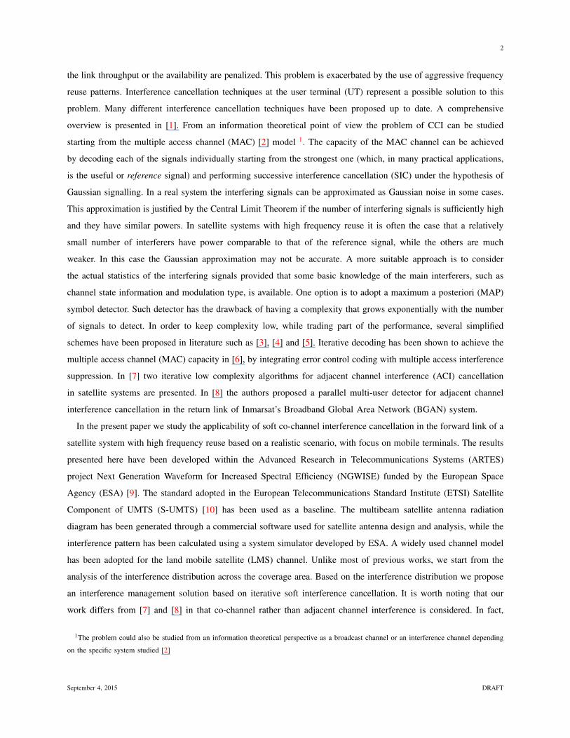
Abstract
We study the applicability of soft interference cancellation in the forward link of multibeam satellite systems
with focus on mobile terminals. We adopt a standard currently used in commercial satellite systems as a reference.
The multibeam satellite antenna radiation diagram has been generated using a physical optics reflector model while a
widely adopted channel model has been used for the land mobile satellite (LMS) channel. The interference pattern has
been derived using a system simulator developed by the European Space Agency (ESA). Starting from the analysis
of the interference pattern we study the application of a low complexity soft interference cancellation scheme for
commercial applications. Our results show that, under realistic conditions, a two-colors frequency reuse scheme can be
employed while guaranteeing service availability across the coverage and keeping the complexity at the user terminals
relatively low.
I. INTRODUCTION
Frequency spectrum scarcity is one of the main capacity-limiting factors in wireless communication systems. A
common practice to overcome bandwidth shortage in both satellite and terrestrial networks using multiple beams/cells
consists in dividing the available spectrum into non overlapping sub-bands (colors) and reuse them over non-adjacent
geographical regions. Coloring schemes with a small number of colors allow for a more efficient utilization of the
spectrum resources, but have the drawback of increasing the co-channel interference (CCI) due to the non-ideal
antennas radiation patterns. Despite the improvements in antennas technology, undesired side lobes are still a
particularly challenging problem in geostationary (GEO) satellite communications, since the interference coming
from co-channel beams can heavily affect the reception of the desired signal at the user terminal such that either
September 4, 2015 DRAFT
2
the link throughput or the availability are penalized. This problem is exacerbated by the use of aggressive frequency
reuse patterns. Interference cancellation techniques at the user terminal (UT) represent a possible solution to this
problem. Many different interference cancellation techniques have been proposed up to date. A comprehensive
overview is presented in [1]. From an information theoretical point of view the problem of CCI can be studied
starting from the multiple access channel (MAC) [2] model 1. The capacity of the MAC channel can be achieved
by decoding each of the signals individually starting from the strongest one (which, in many practical applications,
is the useful or reference signal) and performing successive interference cancellation (SIC) under the hypothesis of
Gaussian signalling. In a real system the interfering signals can be approximated as Gaussian noise in some cases.
This approximation is justified by the Central Limit Theorem if the number of interfering signals is sufficiently high
and they have similar powers. In satellite systems with high frequency reuse it is often the case that a relatively
small number of interferers have power comparable to that of the reference signal, while the others are much
weaker. In this case the Gaussian approximation may not be accurate. A more suitable approach is to consider
the actual statistics of the interfering signals provided that some basic knowledge of the main interferers, such as
channel state information and modulation type, is available. One option is to adopt a maximum a posteriori (MAP)
symbol detector. Such detector has the drawback of having a complexity that grows exponentially with the number
of signals to detect. In order to keep complexity low, while trading part of the performance, several simplified
schemes have been proposed in literature such as [3], [4] and [5]. Iterative decoding has been shown to achieve the
multiple access channel (MAC) capacity in [6], by integrating error control coding with multiple access interference
suppression. In [7] two iterative low complexity algorithms for adjacent channel interference (ACI) cancellation
in satellite systems are presented. In [8] the authors proposed a parallel multi-user detector for adjacent channel
interference cancellation in the return link of Inmarsat’s Broadband Global Area Network (BGAN) system.
In the present paper we study the applicability of soft co-channel interference cancellation in the forward link of a
satellite system with high frequency reuse based on a realistic scenario, with focus on mobile terminals. The results
presented here have been developed within the Advanced Research in Telecommunications Systems (ARTES)
project Next Generation Waveform for Increased Spectral Efficiency (NGWISE) funded by the European Space
Agency (ESA) [9]. The standard adopted in the European Telecommunications Standard Institute (ETSI) Satellite
Component of UMTS (S-UMTS) [10] has been used as a baseline. The multibeam satellite antenna radiation
diagram has been generated through a commercial software used for satellite antenna design and analysis, while the
interference pattern has been calculated using a system simulator developed by ESA. A widely used channel model
has been adopted for the land mobile satellite (LMS) channel. Unlike most of previous works, we start from the
analysis of the interference distribution across the coverage area. Based on the interference distribution we propose
an interference management solution based on iterative soft interference cancellation. It is worth noting that our
work differs from [7] and [8] in that co-channel rather than adjacent channel interference is considered. In fact,
1The problem could also be studied from an information theoretical perspective as a broadcast channel or an interference channel depending
on the specific system studied [2]
September 4, 2015 DRAFT
3
whenever standard channel spacing is considered 2 and an aggressive frequency reuse scheme is applied, indeed
CCI becomes the most relevant source of interference in the system as its level is much higher with respect to that
of the ACI. Unlike in [8] we consider the forward link rather than the return link. Interference cancellation in the
forward link is constrained by the complexity at the UT, especially in the LMS context. We show that, assuming
a realistic interference distribution across the coverage, the optimal detector can be applied at the receiver with
affordable complexity if the same symbol rate is kept across all co-channel signals coming from the satellite. Our
results show that frame error rates as low as 10−3 can be achieved in the whole covered area while using a two-color
frequency reuse scheme. Such a high frequency reuse can lead to a potential increase in spectral efficiency with
respect to coloring schemes usually adopted in commercial satellite systems. Furthermore, we study the effect of
signals misalignment at the satellite showing that misalignment errors can be tolerated up to a certain extent.
The rest of the paper is organized as follows. In Section II the system model is presented while in Section III
we describe the proposed solution specifying the required modifications to ETSI standard [12]. In the same section
we perform a preliminary evaluation of the proposed interference cancellation method. The numerical results are
presented in Section IV while Section V summarizes the main contributions of the paper.
II. SYSTEM MODEL
We consider the forward link of an interactive geostationary (GEO) multibeam satellite system with 210 user-
link beams operating in L/S band. Each beam occupies half of the available user-link bandwidth and a two-color
frequency reuse pattern is adopted, with a single polarization per beam. The coloring scheme is such that the same
color is used in beams along the same parallel while colors alternate along meridians.
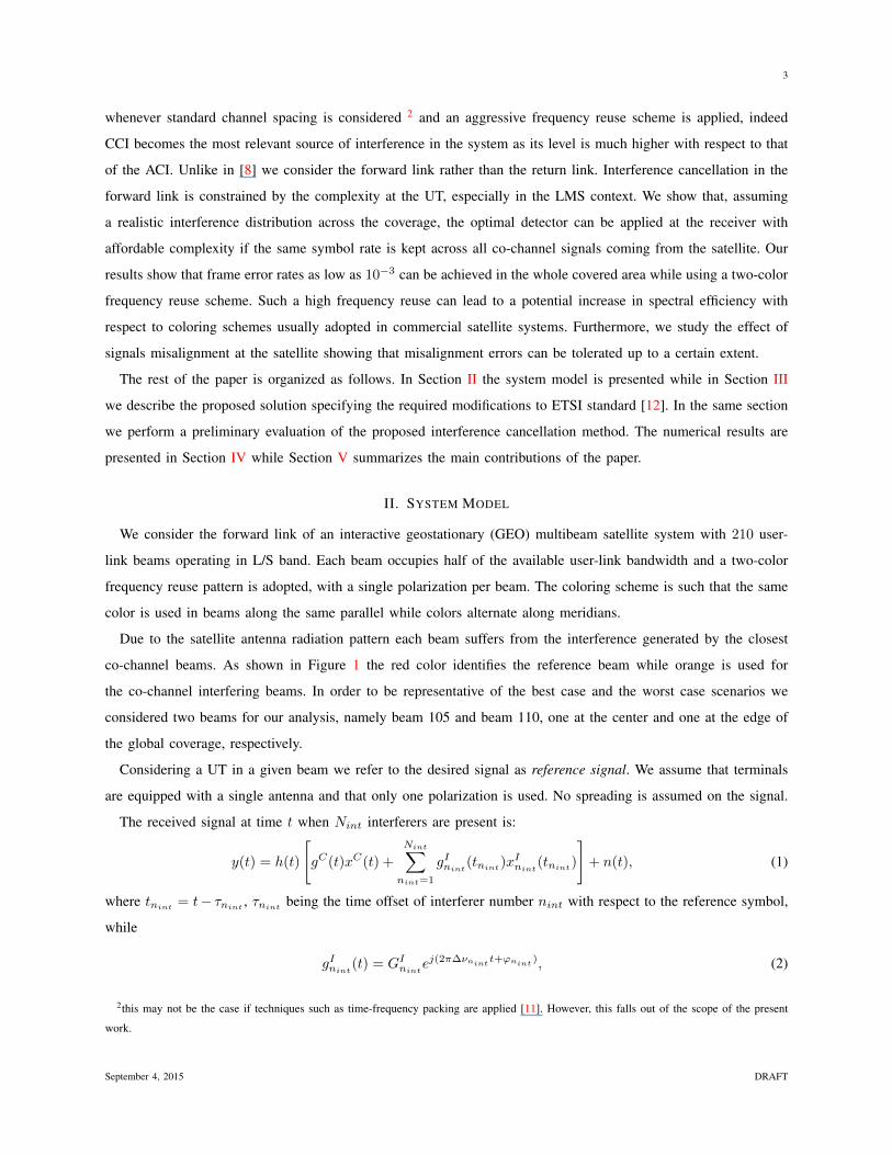
Due to the satellite antenna radiation pattern each beam suffers from the interference generated by the closest
co-channel beams. As shown in Figure 1 the red color identifies the reference beam while orange is used for
the co-channel interfering beams. In order to be representative of the best case and the worst case scenarios we
considered two beams for our analysis, namely beam 105 and beam 110, one at the center and one at the edge of
the global coverage, respectively.
Considering a UT in a given beam we refer to the desired signal as reference signal. We assume that terminals
are equipped with a single antenna and that only one polarization is used. No spreading is assumed on the signal.
The received signal at time t when Nint interferers are present is:
y(t) = h(t)
[gC(t)xC(t) +
Nint∑nint=1
gInint(tnint)x
Inint
(tnint)
]+ n(t), (1)
where tnint = t− τnint , τnint being the time offset of interferer number nint with respect to the reference symbol,
while
gInint(t) = GInint
ej(2π∆νnintt+ϕnint
), (2)
2this may not be the case if techniques such as time-frequency packing are applied [11]. However, this falls out of the scope of the present
work.
September 4, 2015 DRAFT

4
Fig. 1. Considered reference and interfering beams and conventional numbering. Reference and interfering beams are shown in red and yellow,
respectively.
GInintbeing the antenna gain of the co-channel interfering beam nint in the direction of the UT, normalized to the
gain of the reference signal, while ∆νnintand ϕnint
are the frequency and phase offsets with respect to the local
oscillator at the UT, respectively. Similarly we defined
gC(t) = GCej(2π∆νCt+ϕC), (3)
with GC = 1.
Signals xC(t) and xInint(t), nint ∈ {1, . . . , Nint}, are the reference (i.e., the desired one) and the interfering
signals, respectively. The interfering signals (and similarly the reference one) can be expressed as
xInint(t) =
NCWNint∑l=1
snint(l)g(t− lTnint
s ), (4)
where g(t) is a root-raised cosine pulse with roll-off α, snint(l) represents the l−th received symbol from interferer
nint, Tnints is the symbol duration while NCW
nintis the number of modulated symbols in a codeword for interferer
September 4, 2015 DRAFT

5
nint. The term h(t) in Eqn. (1) takes into account the channel effect (phase rotation and propagation loss). Note
that h(t) is a common multiplying factor for all signals, since all waveforms originate from the same spacecraft
and in the forward link all signals cover the same path to the UT. We assume that the maximum frequency offset
is such that ∆νnintTS � 1/100, ∀nint ∈ {1, . . . , Nint}. The sample taken at time tk after matched filtering and
sampling of signal y(t) is:
yk = h(tk)
gC(tk)s(k) +
Nint∑nint=1
gInint(tnint
k )
NCWnint∑l=1
snint(l)g(tnint
k − lTnints )
+ wk, (5)
where tnint
k = tk−τnintwhile wk’s are independently and identically distributed (i.i.d.) zero mean complex Gaussian
random variables with variance σ2 in each component. The interfering signals gains GInintdepend on the satellite
antenna radiation pattern. Thus, the use of a realistic antenna pattern is of fundamental importance for the selection
and the performance assessment of an adequate interference cancellation technique at the UT. In the following we
give details about the antenna pattern and the system model used in the present paper.
A. System Simulations and Antenna Pattern Models
This section describes the system simulator used to compute the interference pattern as well as the models used
to create the considered antenna pattern.
The ESA satellite communication systems analysis tool, developed in MATLAB, performs a multi-dimensional
space-time link budget over a uniform latitude-longitude grid of users, averaging over a user-defined set of time
availabilities with the related attenuations and probabilities. The reference propagation models are based on ITU
recommendation [13] and it is assumed that the traffic request among different beams is uniform. For the sake of this
study we focus on clear sky conditions, since atmospheric attenuation does not represent a serious impairment in L/S
band. Each user of the grid is assigned to a specific beam if the gain of such beam in its location is the highest across
the coverage. Then, based on the frequency plan and on the consequent beam coloring, the resulting interference
pattern and distribution are calculated. The simulated system foresees the use of Adaptive Coding and Modulation
(ACM) that enables each user to select the most efficient modulation and coding (ModCod) scheme allowed by the
link condition. In general the ACM in LMS systems is more challenging with respect to the case of fixed terminals
due to the rapid changes in the communication channel induced by the terminal motion. In [12] a return channel is
used to feed-back the measured SNR (or SINR) to the Bearer Control Layer. The information is used at the control
unit to select the bearer according to a target QoS. Such system is used to adapt the communication rate to the
long-term channel variations only, since short-term fading is covered by the link margin [12, Section 7]. Further
analysis in the implementation of the ACM mechanism is out of the scope of this paper.
The downlink signal-to-interference ratio (in linear scale) in the point x belonging to beam i is given by:
(C
I
)DLco
(x) =PTX SAT (i)GsatTXco−po
(i, x)∑Nco−ch
j=1,j 6=i PTX SAT (j)GsatTXco−po(j, x)
, (6)
where:
September 4, 2015 DRAFT
6
• PTX SAT (i) is the saturated power per carrier of beam i
• GsatTXco−po(i, x) is the co-polar satellite TX antenna gain of beam i in the location x
• PTX SAT (j) is the saturated power per carrier of beam j; in the following it is assumed that all the carriers
have equal power and therefore this term can be assumed to be a constant
• GsatTXco−po(j, x) is the co-polar satellite TX antenna gain of co-channel beam beam j in the location x.
We assume that solid state power amplifiers (SSPAs) are used on-board the satellite payload. In this analysis we
focus on the first Nco strongest interferers received at the user terminal and define for each of them:(C
Ij
)co
(x) =GsatTXco−po
(i, x)
GsatTXco−po(j, x)
, (7)
as the signal to co-channel interference related to the j-th co-channel interferer, assuming that Ij ≥ Ij+1 ∀j ∈
{1, . . . , Nco} and INco+1 = 0. As for the considered antenna pattern, a commercial software for antenna design
analysis and coverage planning has been used to reproduce a beam pattern similar to the one of a commercial satellite
system [14]. The software is based on physical optics reflector modeling and allows for accurate characterization
of the directivity of both the co-polar and the cross-polar fields, as well as scan-aberrations and losses [15].
A geostationary satellite in the 25 deg East orbital position has been considered. The ETSI standard [12] was
considered for the PHY layer
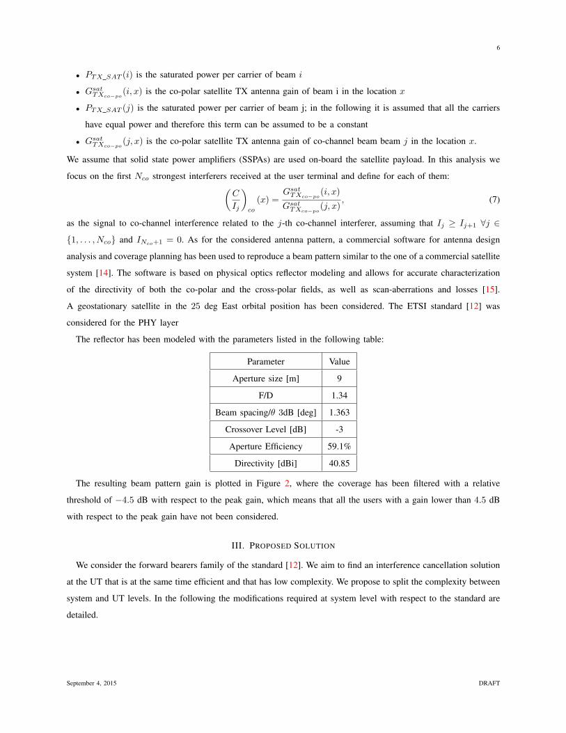
The reflector has been modeled with the parameters listed in the following table:
Parameter Value
Aperture size [m] 9
F/D 1.34
Beam spacing/θ 3dB [deg] 1.363
Crossover Level [dB] -3
Aperture Efficiency 59.1%
Directivity [dBi] 40.85
The resulting beam pattern gain is plotted in Figure 2, where the coverage has been filtered with a relative
threshold of −4.5 dB with respect to the peak gain, which means that all the users with a gain lower than 4.5 dB
with respect to the peak gain have not been considered.
III. PROPOSED SOLUTION
We consider the forward bearers family of the standard [12]. We aim to find an interference cancellation solution
at the UT that is at the same time efficient and that has low complexity. We propose to split the complexity between
system and UT levels. In the following the modifications required at system level with respect to the standard are
detailed.
September 4, 2015 DRAFT

7
Fig. 2. Antenna beam pattern gain [dBi].
A. System Level
The modifications that would be required to [12] are hereafter specified and the related implications and feasibility
discussed.
1) It is assumed that the symbol rate RIs = 1/T Is of the strongest interferer is the same as that of the reference
signal RCs = 1/Ts, Ts being the symbol period of the reference signal. Although in principle different channel
code rates, modulations and FEC block sizes may be used in the two signals, the simulation results we present
in Section IV show that there are some restrictions on the modulations and code rates that can be adopted.
Note that assuming the same symbol rate for the reference and the interfering signals implies Tnints = Ts,
∀nint ∈ {1, . . . , Nint}, in expression (5).
2) The symbols of reference and interfering signals are aligned such that the intersymbol interference (ISI)-free
sample instants of the reference signal correspond to the ISI-free sample instants of the interferer, which
implies τnint= 0 ∀nint ∈ {1, . . . , Nint} in expression (5). However, in Section IV we show that this
constraint can be relaxed up to a certain extent.
3) The receiver knows the modulation used by the interferer. This information can be made available to the
UT through the global beam and using knowledge of the user position, which is currently foreseen in [12]
through the GPS signal. Knowing the position with respect to the reference beam, a user could derive which
is the strongest interfearing beam. The information about the modulation used in each beam (and thus also in
September 4, 2015 DRAFT

8
the interfearing beam) during a given time slot is transmitted over the global beam. We use this assumption
as it simplifies the description of the proposed scheme, although in Section IV we will show that it can be
actually removed.
B. Iterative SISO Decoder at the User Terminal
We assume that the channel of both the reference signal and the strongest interferers as well as the ISI-free sample
instants of the reference signal can be estimated. This assumption is usually taken in most multi-user detection
(MUD) systems. Channel estimation can be performed using the pilot symbols inserted at regular intervals in the
frame as foreseen in [12]. In case the pilot symbols of reference and interfering signal overlap, joint estimation
methods may be adopted (e.g., E-M algorithm [16])3. An extensive literature is available on the subject and further
analysis is out of the scope of this paper. We further assume that conditions 1→ 3 described in Section III-A hold.
In case no interference is present, in a typical receiver the turbo decoder is fed with the log-likelihood ratio (LLR)
vector of the sampled received signal. Let R be the channel code rate. The mb-th component, mb ∈ {1, . . . , RN cwC }
of the LLR vector for QPSK signalling and using the Grey mapping scheme of [10] can be expressed as:
LLRmb= log
(Pr{bmb
= 1 |yk }Pr{bmb
= 0 |yk }
)= log
(Pk,s2 + Pk,s3Pk,s0 + Pk,s1
), (8)
for mb = 2k − 1, while
LLRmb= log
(Pk,s1 + Pk,s3Pk,s0 + Pk,s2
), (9)
for mb = 2k, where Pk,sn is the probability to observe the sample yk conditioned to the transmission of the symbol
sn, n ∈ {0, 1, 2, 3}, while bmbindicates the mb-th coded bit in the transmitted codeword. Eqn. (8), and similarly
Eqn. (9), is derived taking into account that, according to the considered mapping, symbols s2 and s3 correspond
to a bit pair with the first bit equal to 1, while the first bit of the pair mapping to s0 and s1 is equal to 0. Eqn. (8)
can be easily extended to the case of 16 QAM modulation. The probability Pksn is proportional to:
Pk,sn ∝ exp
{|yk − h(tk)GCsn|2
2σ2
}. (10)
In the case of a single interferer with constellation size M , the probability that the k-th symbol of the reference
signal s(k) is equal to sn can be expressed as:
Pk,sn =
M−1∑m=0
PsImPk,sn,sIm , (11)
where Pk,sn,sIm represents the probability to receive yk conditioned to symbols sn and sIm in the reference and
in the interfering signals, respectively, while PsIm represents the probability of transmitting symbol sIm, which is
assumed to be equal to 1/M . The probability Pk,sn,sIm is proportional to:
Pk,sn,sIm ∝ exp
{ |yk − h(tk)gC(tk)sn − h(tk)gInint(tk)sIm|2
2σ2
}. (12)
3A similar problem has been addressed in [17] and [18] where the feasibility of the joint estimation of phase, amplitude and frequency offsets
of colliding signals is studied.
September 4, 2015 DRAFT

9
This can be easily extended to the case of a generic number of interferers Nint each with its phase and frequency
offsets and amplitude, leading to the following expression for the optimal symbol detector,
Pk,sn =
M1−1∑m1=0
· · ·MNint
−1∑mNint
=0
Nint∏j=1
PsIjPk,sn,sIm1,...,sImNint
, (13)
where Mnintis the constellation size of interferer number nint. The complexity of expression (13) grows expo-
nentially with the number of interferers.
Once the a-priori probabilities for the desired signal have been derived they can be used to calculate the L-values
that are fed to the turbo decoder. In this case the only modification at the receiver side with respect to the standard
terminal is limited to the signal detector, while no modification would be needed to the decoder. The performance of
the receiver in terms of FER (and potentially in terms of throughput, as higher ModCods could be adopted) can be
further improved through an iterative detection-decoding scheme. The iterative process can be implemented as done
in the benchmark system of [3, Fig. 1], in which the receiver at each iteration jointly detects all the received signals
in a parallel fashion and then feeds the a-priori probability for each of them to a distinct decoder after subtracting
the intrinsic information. We opted for a scheme which is more suited for an implementation with a single decoder,
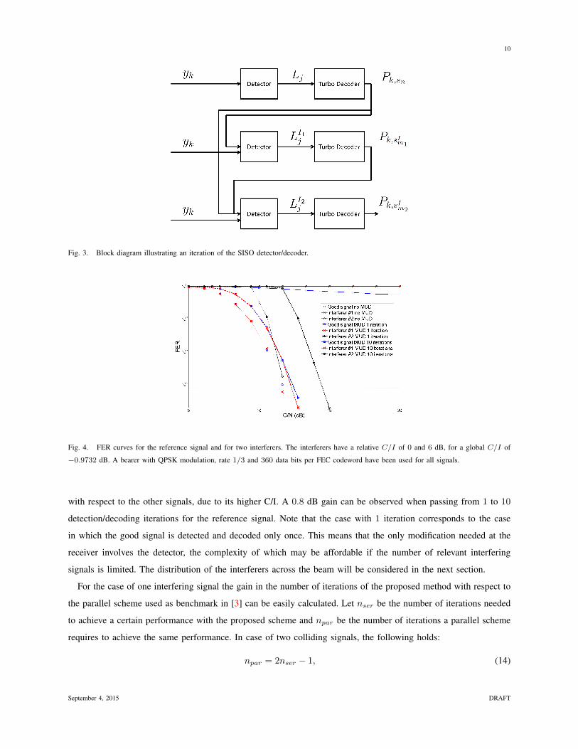
namely a joint soft input-soft output (SISO) detector with serial decoding, which is shown in Fig. 3. In the figure
the block diagram describing one detection-decoding iteration is shown for the case of two interferers. Signals are
detected in decreasing order of strength. Each iteration consists into the following steps. First the detector calculates
the L-value Lj for the reference signal and passes it to the turbo decoder. The decoder outputs a soft estimation
of the channel symbols relative to the desired signal (Pk,sn in the figure). Such estimation is then fed again to the
detector together with the channel output and an estimation of the first (i.e. the most powerful) interferer is obtained.
The educated guess obtained so far for the symbol probabilities of the reference signal and the first interferer are
then fed to the detector together with the channel output in order to estimate the second interferer. At this point
the second iteration starts with the detector using at each step the updated estimates of the symbol probabilities.
Note that, although in Fig. 3 three detectors and three decoders are shown, a single detector/decoder can be used in
practice. Note also that in the proposed scheme the decoding step within a given iteration can not be done in parallel
as in [3], because each decoding stage uses the output of the previous one. However a parallel decoding would
require as many decoders as the number of signals to decode, with a significant increase in complexity and cost of
the UT that, especially for mobile users, may be harmful from both an implementation and an economical point
of view. Moreover, as shown further in this section, although the time required by one iteration of the proposed
scheme is larger with respect to a parallel one, the serial scheme has a faster convergence. This translates in a
reduced number of iterations required to achieve a target performance.
In Fig. 4 the FER attained with the soft successive interference cancellation described so far is shown for the
case of two interferers. The C/I relative to the first interferer (interferer #1) is 0 dB, i.e., it has the same power
of the received signal, while the C/I relative to the other interferer is 6 dB, for a global C/I of −0.9732 dB.
The “no MUD” curve in the figure has been derived by treating the interferers as noise and increasing the value
of the estimated noise variance passed to the turbo decoder accordingly. The second interferer has a worse FER
September 4, 2015 DRAFT
10
Fig. 3. Block diagram illustrating an iteration of the SISO detector/decoder.
Fig. 4. FER curves for the reference signal and for two interferers. The interferers have a relative C/I of 0 and 6 dB, for a global C/I of
−0.9732 dB. A bearer with QPSK modulation, rate 1/3 and 360 data bits per FEC codeword have been used for all signals.
with respect to the other signals, due to its higher C/I. A 0.8 dB gain can be observed when passing from 1 to 10
detection/decoding iterations for the reference signal. Note that the case with 1 iteration corresponds to the case
in which the good signal is detected and decoded only once. This means that the only modification needed at the
receiver involves the detector, the complexity of which may be affordable if the number of relevant interfering
signals is limited. The distribution of the interferers across the beam will be considered in the next section.
For the case of one interfering signal the gain in the number of iterations of the proposed method with respect to
the parallel scheme used as benchmark in [3] can be easily calculated. Let nser be the number of iterations needed
to achieve a certain performance with the proposed scheme and npar be the number of iterations a parallel scheme
requires to achieve the same performance. In case of two colliding signals, the following holds:
npar = 2nser − 1, (14)
September 4, 2015 DRAFT
11
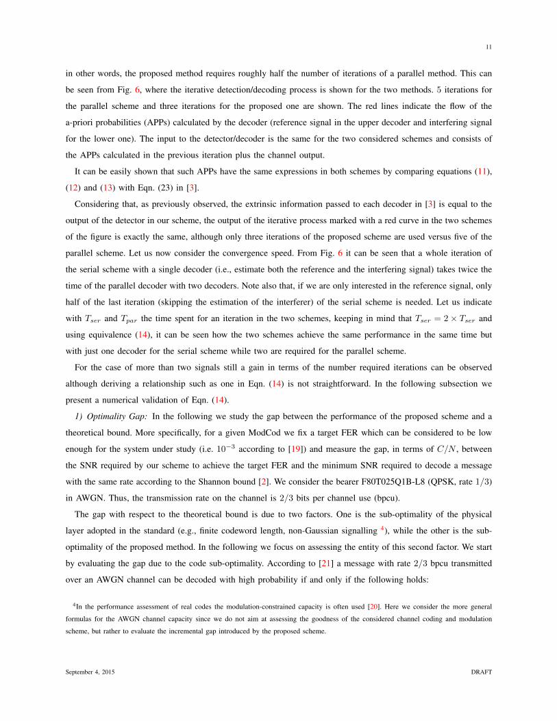
in other words, the proposed method requires roughly half the number of iterations of a parallel method. This can
be seen from Fig. 6, where the iterative detection/decoding process is shown for the two methods. 5 iterations for
the parallel scheme and three iterations for the proposed one are shown. The red lines indicate the flow of the
a-priori probabilities (APPs) calculated by the decoder (reference signal in the upper decoder and interfering signal
for the lower one). The input to the detector/decoder is the same for the two considered schemes and consists of
the APPs calculated in the previous iteration plus the channel output.
It can be easily shown that such APPs have the same expressions in both schemes by comparing equations (11),
(12) and (13) with Eqn. (23) in [3].
Considering that, as previously observed, the extrinsic information passed to each decoder in [3] is equal to the
output of the detector in our scheme, the output of the iterative process marked with a red curve in the two schemes
of the figure is exactly the same, although only three iterations of the proposed scheme are used versus five of the
parallel scheme. Let us now consider the convergence speed. From Fig. 6 it can be seen that a whole iteration of
the serial scheme with a single decoder (i.e., estimate both the reference and the interfering signal) takes twice the
time of the parallel decoder with two decoders. Note also that, if we are only interested in the reference signal, only
half of the last iteration (skipping the estimation of the interferer) of the serial scheme is needed. Let us indicate
with Tser and Tpar the time spent for an iteration in the two schemes, keeping in mind that Tser = 2× Tser and
using equivalence (14), it can be seen how the two schemes achieve the same performance in the same time but
with just one decoder for the serial scheme while two are required for the parallel scheme.
For the case of more than two signals still a gain in terms of the number required iterations can be observed
although deriving a relationship such as one in Eqn. (14) is not straightforward. In the following subsection we
present a numerical validation of Eqn. (14).
1) Optimality Gap: In the following we study the gap between the performance of the proposed scheme and a
theoretical bound. More specifically, for a given ModCod we fix a target FER which can be considered to be low
enough for the system under study (i.e. 10−3 according to [19]) and measure the gap, in terms of C/N , between
the SNR required by our scheme to achieve the target FER and the minimum SNR required to decode a message
with the same rate according to the Shannon bound [2]. We consider the bearer F80T025Q1B-L8 (QPSK, rate 1/3)
in AWGN. Thus, the transmission rate on the channel is 2/3 bits per channel use (bpcu).
The gap with respect to the theoretical bound is due to two factors. One is the sub-optimality of the physical
layer adopted in the standard (e.g., finite codeword length, non-Gaussian signalling 4), while the other is the sub-
optimality of the proposed method. In the following we focus on assessing the entity of this second factor. We start
by evaluating the gap due to the code sub-optimality. According to [21] a message with rate 2/3 bpcu transmitted
over an AWGN channel can be decoded with high probability if and only if the following holds:
4In the performance assessment of real codes the modulation-constrained capacity is often used [20]. Here we consider the more general
formulas for the AWGN channel capacity since we do not aim at assessing the goodness of the considered channel coding and modulation
scheme, but rather to evaluate the incremental gap introduced by the proposed scheme.
September 4, 2015 DRAFT

12
log2
(1 +
C
N
)≥ 2
3, (15)
which imposes the following condition on the SNR:
C
N≥ 22/3 − 1 = 0.5874 ≈ −2.3 dB. (16)
The physical layer described in [10] for the considered ModCod requires a C/N of about 0.2 dB in order to achieve
a FER of 10−3 (see Fig. 5). This means that the code loses about 2.5 dB with respect to the theoretical bound.
Now let us consider the case in which two signals are transmitted with the same power C over an AWGN
channel. In the system under study the receiver is interested in decoding only one of the two messages. According
to the results and under the assumptions relative to the corner points of the capacity region of the MAC channel
and the degraded broadcast channel [2], the optimal strategy for a receiver interested only in the strongest signal is
to treat the interferer as noise. In such case the receiver can decode successfully the desired message if and only if:
log2
(1 +
C
N + C
)≥ 2
3, (17)
which leads to:
C
N≥ 22/3 − 1
2− 22/3
= 1.4237 ≈ 1.5 dB. (18)
Fig. 5. FER in AWGN, QPSK rate 1/3 used in all signals. The Shannon limit for the case of no interference and for the case with one
interferer with C/I = 0 dB are also shown. The FER for a scheme in which the signals are decoded in parallel rather than serially (as in the
proposed scheme) is also shown. It can be seen how the loss of the proposed scheme with respect to the Shannon limit for a FER of 10−3 is
only slightly larger than the loss due to the code (curves in case of no interference). It can be also seen how the parallel scheme requires more
iterations with respect to the proposed scheme.
The proposed scheme achieves the target FER in case of a single interferer at an SNR of about 4.8 dB with 15
iterations, with a loss of 3.3 dB with respect to the theoretical bound, as shown in Fig. 5. Although the loss may
September 4, 2015 DRAFT
13
Fig. 6. Comparison between the proposed method and a parallel MUD scheme. In red we put into evidence the decoding path for the reference
signal. In the figure we show only the propagation of the APPs. In the practical implementation of both schemes the detector takes as input
also the received signal, not indicated for sake of clarity.
seem significant, we note how it is only 0.8 dB larger than the loss due to the code in the case of no interference.
This suggests that the total loss of 3.3 dB is mainly due to the non-ideal physical layer and only to a relatively
minor extent to the proposed scheme, which results to be highly efficient if enough iterations are allowed. The loss
due to the proposed scheme may be further reduced by increasing the number of iterations. Note that the considered
bearer has a burst length of 544 symbols, which is relatively short if compared to other standards. Using more
powerful channel codes would significantly reduce the gap due to the specifical physical layer considered although
would increase latency and memory requirements at the UT. In Fig. 5 the FER for a scheme in which the signals
are decoded in parallel within an iteration rather than serially (as in the proposed scheme) is also shown.
It can be seen how the parallel scheme requires more iterations with respect to the proposed serial scheme, in
accordance with Eqn. (14). As previously mentioned, for a fair comparison, we point out that one iteration of the
proposed scheme takes twice the time of one iteration in the parallel scheme. Thus, according to Fig. 6 exactly the
same time is required to obtain the same performance in both schemes. This means that our scheme achieves the
same convergence speed of the parallel one using a single decoder rather than two, with an important saving in
terms of terminal complexity.
IV. NUMERICAL RESULTS
In the following we evaluate the performance of the proposed algorithm for the scenario described in Section II.
We start by describing in detail the reference scenario and the interference distribution generated by the system
level simulator presented in Section II. The beam numbering and geographical location are shown in Fig. 1. In
Table I we show the C/I related to each of the 10 strongest interferers for both beam 105 and 110 in two points,
namely at the center of the beam (CoB) and at the edge of the beam (EoB).
The numbering relative to the interferers is given according to Figure 7, where the central rectangle represents
the reference beam while the yellow rectangles represent the strongest co-channel interferers.
September 4, 2015 DRAFT

14
TABLE I
TABLE WITH FOUR SAMPLES OF THE INTERFERENCE PATTERN. EACH ROW CONTAINS THE C/I RELATED TO THE TEN STRONGEST
INTERFERING SIGNALS FOR EITHER A CENTER-OF-BEAM (COB) POINT OR AN EDGE-OF-BEAM (EOB) POINT IN BEAMS 105 AND 110. THE
TOTAL C/I IS ALSO REPORTED FOR EACH CASE [19].
C/I [dB]C/I Total [dB]
Beam 1 2 3 4 5 6 7 8 9 10
105CoB 37.1107 21.5885 32.1618 37.2214 17.9294 14.5272 27.3961 31.9697 20.7406 29.2564 11.46467
EoB 15.6046 15.5337 29.8048 15.8007 0.3881 15.1211 21.4581 44.3936 38.1297 21.875 -0.17835
110CoB 30.3903 19.541 32.9636 35.0503 13.7636 12.1374 21.4154 29.4771 18.9879 30.8531 8.607253
EoB 27.2207 29.9124 22.4402 17.9726 0.1185 11.5821 18.8873 14.2254 15.2343 27.9627 -0.6047
Fig. 7. Interference pattern and conventional numbering of the co-channel beams. The central red rectangle represents the reference beam,
while the yellow rectangles represent the ten strongest interfering beams.
With reference to Table I, it can be seen that in the EoB cases the power of the interferer number 5 is comparable
to that of the reference signal while the second strongest interferer is attenuated more than 11 dB. On the other
hand, in the CoB the strongest interferer is at least 12 dB lower than the reference signal. Let us consider the
worst case scenario, i.e., the EoB. In this case there is only one strong interferer plus nine interferers with a
relatively weak power, that, by the Central Limit Theorem, can be modeled as Gaussian noise. Trying to apply
MUD to these low-power interferers is not likely to have a relevant impact on the system performance while it
would increase significantly the complexity of the receiver. A better choice is to apply the MUD to the desired
signal and the strongest interferer while treating the rest of the interferers as noise. In order to understand whether
the assumption of having at most one significant interferer is realistic in each point of the beam footprint, we
analyzed the distribution of the total C/I across the whole beam. The distribution is shown in Fig. 8, where three
cases have been considered for each point in the two beams: i) all the interferers are present (top-left), ii) only the
first strongest interferer has been removed (bottom-left) iii) the first two strongest interferers have been removed
(bottom-right). From the figure it can be seen that the total C/I reaches negative values, in logarithmic scale, in
some areas of the beam (e.g., in the EoB points considered in the table shown in Table I) when all the interferers
are present. Removing the strongest interferer determines a minimum C/I larger than or equal to 6 dB in any
point of the two considered beams. We further notice that the cancellation of the second strongest interferer further
increases the minimum C/I of only about 1-1.5 dB. From the analysis of Fig. 8 we conclude that the total C/I
is mainly limited by the first strongest interferer while the second one has only limited impact on performance.
We propose therefore to deal with only one interfering signal while treating the others as noise in order to keep
the complexity low. In order to further reduce the complexity we apply just one iteration of the iterative decoding
September 4, 2015 DRAFT

15
Fig. 8. Distribution of interference across the covered area in case: 1) all interferers are present (top-left), 2) the strongest interferer has been
removed (bottom-left), 3) the two strongest interferers have been removed (bottom-right). The CDF of the difference between the two strongest
interferers across the beam is also shown (top-right).
process previously described and shown in Fig. 3 for the case of two interferers. In this way the only modification
needed at the decoder side is in the detector, for which the a-priori probability in case of one interferer reduces to:
Pk,sn =
M−1∑m=0
exp
{|yk − hgC(tk)sn − hgI(tk)sIm|2
2σ2eq
}, (19)
M being the cardinality of the interferer’s constellation. The correspondent block scheme is shown in Fig. 9.
In order to take into account the influence of the other interferers (which reduces the reliability of the detection)
in the received signal’s statistics we increase σ2eq by several dBs (6 in the following simulations) with respect to the
actual variance of the thermal noise σ2. The optimal choice would be to choose the value of σeq by estimating the
noise-plus-interference power. However in practice keeping a fixed value of the variance can be a good compromise
since i) the thermal noise component can be either given by the terminal manufacturer or easily estimated, while
the power due to residual interference may not be easy to measure, as the received signal is made up by the sum
of the (strong) reference signal, a (possibly strong) dominant interferer and the residual interferer (estimation of the
residual interference power in such conditions would increase the complexity of the receiver) and ii) the FER shows
little sensibility to the exact value of σeq . In the simulations presented in the following the signal model described
in equations 1-5 has been adopted: all 10 interferers have been simulated including channel code, modulation and
September 4, 2015 DRAFT

16
Fig. 9. Proposed simplified SIC scheme. Only the strongest interferer is taken into account and no iterative detection/decoding is applied (i.e.,
reference signal is detected as described in Section III and decoded using the turbo decoder specified in [10]). Optionally, also the strongest
interfering signal can be decoded.
channel effect, and scaling the powers according to Table I. We first present the results obtained in AWGN channel
and then those for the LMS scenario. The simulation setup for the two cases is depicted in Fig. 10. The simplified
scheme shown in Fig. 9 (i.e., the received signal passes through the detector and through the turbo decoder just
once) has been used.
Fig. 10. Simulation setup in AWGN and LMS channels.
A. AWGN Channel
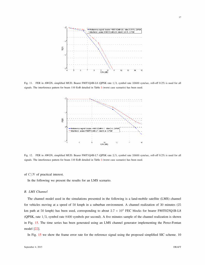
In figures 11, 12 and 13 we show the FER curves for the simplified SIC in AWGN using the interference pattern
detailed in Table I. Different combinations of MODECODs available in the standard [12] have been used, namely
QPSK rate 1/3 for all signals in Fig. 11, QPSK with rate 2/5 for all signals in Fig. 12 and QPSK while rate 1/3
for the reference signal and 16 QAM rate 1/3 for interferers are used in Fig. 13.
From the plots it emerges that the target FER of 10−3 can be achieved using QPSK modulation in all signals up
to rate 2/5 while if 16 QAM is used in one of (or both) the signals the target FER cannot be achieved for values
September 4, 2015 DRAFT
17
Fig. 11. FER in AWGN, simplified MUD. Bearer F80T1Q4B-L8 (QPSK rate 1/3, symbol rate 33600 sym/sec, roll-off 0.25) is used for all
signals. The interference pattern for beam 110 EoB detailed in Table I (worst case scenario) has been used.
Fig. 12. FER in AWGN, simplified MUD. Bearer F80T1Q4B-L7 (QPSK rate 2/5, symbol rate 33600 sym/sec, roll-off 0.25) is used for all
signals. The interference pattern for beam 110 EoB detailed in Table I (worst case scenario) has been used.
of C/N of practical interest.
In the following we present the results for an LMS scenario.
B. LMS Channel
The channel model used in the simulations presented in the following is a land-mobile satellite (LMS) channel
for vehicles moving at a speed of 50 kmph in a suburban environment. A channel realization of 30 minutes (25
km path at 50 kmph) has been used, corresponding to about 2.7 × 10⁴ FEC blocks for bearer F80T025Q1B-L8
(QPSK, rate 1/3, symbol rate 8400 symbols per second). A five minutes sample of the channel realization is shown
in Fig. 15. The time series has been generated using an LMS channel generator implementing the Perez-Fontan
model [22].
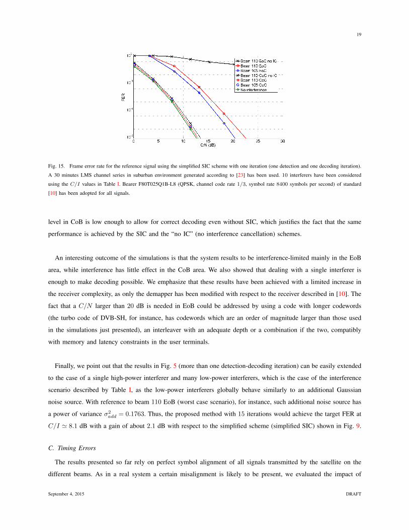
In Fig. 15 we show the frame error rate for the reference signal using the proposed simplified SIC scheme. 10
September 4, 2015 DRAFT

18
Fig. 13. FER in AWGN, simplified MUD. Bearer F80T1Q4B-L8 (QPSK rate 1/3, symbol rate 33600 sym/sec, roll-off 0.25) is used for
the reference signal while bearer F80T1X4B-L3 (16 QAM rate 1/3, symbol rate 33600 symbols per second , roll-off 0.25) is used for the
interferers. Note that rate 1/3 is the lowest code rate available in [10]). The interference pattern for beam 110 EoB detailed in Table I (worst
case scenario) has been used.
Fig. 14. Five minutes sample of the 30 minutes channel series (power in logarithmic scale) used in the simulations. The time series has been
generated with a channel simulator implementing the LMS Perez-Fontan model in suburban environment, vehicle speed 50 kmph and satellite
elevation 30o.
interferers have been considered using the C/I values in Table I. Bearer F80T025Q1B-L8 (QPSK, rate 1/3) of
standard [12] has been adopted for all signals.
Fig. 15 shows that the SIC scheme reaches the target FER of 10−3 in all the considered cases, showing a neat
enhancement with respect to the case in which no interference cancellation is applied. Thus, it can be seen that
decoding is possible in all considered points, while it is not feasible without the MUD algorithm. A relatively high
C/N is required in order to fulfill FER requirements in EoB which is due partly to the challenging propagation
scenario. As a matter of facts it can be seen in Fig. 15 that, even in case no interference is present in the system,
a C/N of about 14 dB is needed to reach a target FER of 10−3 We also note that the FER obtained in the
LMS channel in case of no interference is almost the same as that in CoB. This is because the total interference
September 4, 2015 DRAFT
19
Fig. 15. Frame error rate for the reference signal using the simplified SIC scheme with one iteration (one detection and one decoding iteration).
A 30 minutes LMS channel series in suburban environment generated according to [23] has been used. 10 interferers have been considered
using the C/I values in Table I. Bearer F80T025Q1B-L8 (QPSK, channel code rate 1/3, symbol rate 8400 symbols per second) of standard
[10] has been adopted for all signals.
level in CoB is low enough to allow for correct decoding even without SIC, which justifies the fact that the same
performance is achieved by the SIC and the “no IC” (no interference cancellation) schemes.
An interesting outcome of the simulations is that the system results to be interference-limited mainly in the EoB
area, while interference has little effect in the CoB area. We also showed that dealing with a single interferer is
enough to make decoding possible. We emphasize that these results have been achieved with a limited increase in
the receiver complexity, as only the demapper has been modified with respect to the receiver described in [10]. The
fact that a C/N larger than 20 dB is needed in EoB could be addressed by using a code with longer codewords
(the turbo code of DVB-SH, for instance, has codewords which are an order of magnitude larger than those used
in the simulations just presented), an interleaver with an adequate depth or a combination if the two, compatibly
with memory and latency constraints in the user terminals.
Finally, we point out that the results in Fig. 5 (more than one detection-decoding iteration) can be easily extended
to the case of a single high-power interferer and many low-power interferers, which is the case of the interference
scenario described by Table I, as the low-power interferers globally behave similarly to an additional Gaussian
noise source. With reference to beam 110 EoB (worst case scenario), for instance, such additional noise source has
a power of variance σ2add = 0.1763. Thus, the proposed method with 15 iterations would achieve the target FER at
C/I ' 8.1 dB with a gain of about 2.1 dB with respect to the simplified scheme (simplified SIC) shown in Fig. 9.
C. Timing Errors
The results presented so far rely on perfect symbol alignment of all signals transmitted by the satellite on the
different beams. As in a real system a certain misalignment is likely to be present, we evaluated the impact of
September 4, 2015 DRAFT

20
alignment (timing) error on the proposed technique. We assume a delay between the ISI-free instants of the reference
signal and the ISI-free instants of all the interferers equal to τ = X × Ts, where Ts is the symbol duration and
X ∈ (0, 1/2) corresponds to the delay normalized to the symbol duration. As in all the other simulations presented
so far, SRRC pulse filters with roll off specified in [10] have been used. Frequency and phase offsets have been
taken into account and the interference pattern of Fig. 8 has been assumed in AWGN channel. In Fig. 16 we show
Fig. 16. FER in AWGN, simplified MUD, QPSK rate 1/3 used in all signals. Curves for different relative delays are shown. Delays are
expressed in fraction of symbol duration Ts.
the FER obtained for different relative delays expressed in percentage of the symbol duration. It can be seen how
a timing offset of up to 15% allows to achieve the target FER. The loss in SNR for an offset of 15% is slightly
larger than 2 dB. If the offset is raised up to 20% the target FER can no longer be achieved within the specified
C/N range ([0− 20] dB).
V. CONCLUSIONS AND DISCUSSION
We studied the application of co-channel soft interference cancellation in multibeam mobile satellite systems with
a dense frequency reuse scheme. We took the ETSI standard [12], currently used in commercial satellite systems,
as a reference and simulated the beam radiation and the interference patterns using a realistic antenna model, while
the calculation of the interference pattern has been carried using a simulator developed by ESA. Due to strong
complexity limitations in mobile terminals, we proposed to move part of the complexity to the system level, by
aligning signals transmitted over different beams and adding specific signalling information in the global beam. We
started from the analysis of the interference levels across the beams selecting two of them as best and worst case
scenarios. We applied a serial iterative detection-decoding scheme with optimal symbol detector. We studied the
gap between the performance of the proposed iterative scheme and the Shannon bound for successive interference
cancellation, showing that most of the loss is due to the non-ideal physical layer considered, while less than an
additional dB of loss is introduced by the proposed scheme. In order to keep the complexity at the receiver low
we also proposed a simplified scheme in which only the detector is modified with respect to the standard [10].
September 4, 2015 DRAFT
21
Our results showed that even under challenging propagation conditions and with strong interference, the simplified
scheme leads to interesting results, achieving a target FER of practical interest. We also showed that the proposed
scheme can, up to a certain extent, tolerate signals misalignment, achieving the target FER for a timing offset of
up to 15%.
The assumption of using the same symbol rate across on all beams may give rise to the objection that different
services and different terminal types may require different symbol rates. The assumption of a fixed symbol rate
across all beams can be actually relaxed in some cases. Specifically, as it is often the case in real systems, more
than one carrier can be assigned to a beam. The solution we propose could be applied also in the case in which,
within a beam, different carriers have different symbol rates. For example, given a beam j, let us refer to the number
of carriers in the beam as N jc . Each of the carriers can have a different symbol rate (and bandwidth). Let us refer
to the symbol rate of the i-th carrier on beam j as Bji . The low complexity SIC can be applied also in this case
provided that the same number of carriers is used in all beams (N jc = N j′
c ∀j, j′) and that carrier i has the same
symbol rate (Bji = Bj′
i ∀j, j′) and the spectral position in all beams. In this way carriers with different symbol
rates could be present in each beam while keeping the complexity at the demodulator low.
Although a single polarization has been considered in the present paper, the same concepts presented here can be
extended to a dually polarized system. In this case one possibility is to consider still a two colors scheme in which
orthogonality is achieved in the polarization rather than in the frequency domain. Considering dual polarization
would double the bandwidth of the system with respect to the single polarization case if the same bandwidth is
kept on each of the polarizations. Further studies are needed to assess the impact cross-polar interference would
have in such context.
As a final remark, a full-scale study of the impact the proposed method would bring in terms of system throughput
and availability, as well as a sensitivity analysis of such impact with respect to the terminal complexity are needed
to have a complete picture. Given the vastity of the subject and for a matter of space, we consider such study as
an interesting subject for future work.
ACKNOWLEDGEMENTS
The present work has been carried out under the ARTES 1 programme founded by the European Space Agency.
This work has been partially funded from the Catalan Government (2009SGR0891).
The research leading to these results has received funding from the Spanish Ministry of Science and Innovation
under projects TEC2011-29006-C03-02 (GRE3N-LINK-MAC) and the Catalan Government (2009SGR0891).
The view expressed herein can in no way be taken to reflect the official opinion of the European Space Agency.
This is a draft version of the following article: G. Cocco, M. Angelone, A.I. Perez-Neira, Co-Channel Interference
Cancellation at the User Terminal in Multibeam Satellite Systems to appear in Wileys International Journal of
Satellite Communications and Networking.
September 4, 2015 DRAFT
22
REFERENCES
[1] J. G. Andrews, “Interference cancellation for cellular systems: a contemporary overview,” IEEE Wireless Comm., vol. 12, no. 2, pp. 19–29,
2005.
[2] T. M. Cover and J. A. Thomas, Elements of Information Theory, second edition ed. John Wiley & Sons, 2006.
[3] X. Wang and H. V. Poor, “Iterative (turbo) soft interference cancellation and decoding for coded CDMA,” IEEE Trans. on Commun.,
vol. 47, no. 7, pp. 1046–1061, 1999.
[4] M. Kopbayashi, J. Boutros, and G. Caire, “Successive interference cancellation with SISO decoding and EM channel estimation,” IEEE
Journal on Selected Areas in Comm., vol. 19, no. 8, pp. 1450–1460, 2001.
[5] G. Colavolpe, D. Fertonani, and A. Piemontese, “SISO detection over linear channels with linear complexity in the number of interferers,”
IEEE Journal of Selected Topics in Signal Processing, vol. 5, no. 8, pp. 1475–1485, 2011.
[6] C. Schlegel, “Achieving the multiple-access capacity of the AWGN channel with iterative processing,” in AESS European Conference on
Satellite Telecommunications (ESTEL), Rome, Italy, Oct. 2012.
[7] B. F. Beidas, H. El-Gamal, and S. Kay, “Iterative interference cancellation for high spectral efficiency satellite communications,” IEEE
Trans. on Comm., vol. 50, no. 1, pp. 31–36, 2002.
[8] M. Moher, W. Zhang, P. Febvre, and J. Rivera-Castro, “Multi-user detection for Inmarsat’s BGAN system,” in Advanced Satellite Multimedia
Systems conf. (ASMS) and Signal Processing for Space Communications workshop (SPSC), Cagliari, Italy, Sep. 2010, pp. 135–140.
[9] European Space Agency, “ESA Artes 1 contract 4000106528/12/nl/nr, next generation waveforms for improved spectral efficiency,”
https://artes.esa.int/projects/next-generation-waveform-improved-spectral-efficiency, 2012-2015.
[10] European Telecommunications Standards Institute, “Satellite component of UMTS (S-UMTS) family SL satellite radio interface; part 2:
Physical layer specifications; sub-part 1: Physical layer interface,” May 2012.
[11] A. Barbieri, D. Fertonani, and G. Colavolpe, “Time-frequency packing for linear modulations: spectral efficiency and practical detection
schemes,” IEEE Trans. on Commun., vol. 57, no. 10, pp. 2951–2959, 2009.
[12] European Telecommunications Standards Institute, “Satellite component of UMTS (S-UMTS) family SL satellite radio interface; part 1:
General specifications; sub-part 3: Satellite radio interface overview,” May 2011.
[13] International Telecommunications Union - Radiocommunications Sector, “Propagation data and prediction methods requred for the design
of Earth-space telecommunication systems: methods requred for the design of Earth-space telecommunication systems,” Reccomendation
ITU-R P.618-10 (10/2009), Oct. 2009.
[14] Inmarsat, “Broadband Global Area Network (BGAN),” http://www.inmarsat.com/services/bgan.
[15] Satsoft, http://www.satsoft.com/.
[16] M. Feder and E. Weinstein, “Parameter estimation of superimposed signals using the EM algorithm,” IEEE Trans. on Acoustics, Speech
and Signal Processing, vol. 36, no. 4, pp. 477–489, Apr. 1988.
[17] G. Cocco, N. Alagha, C. Ibars, and S. Cioni, “Practical issues in multi-user physical layer network coding,” in IEEE Advanced Satellite
Mobile Systems conf. (ASMS), Baiona, Spain, Sep. 2012.
[18] K. Zidane, J. Lacan, M.-L. Boucheret, and C. Poulliat, “Improved channel estimation for interference cancellation in random access methods
for satellite communications,” in Advanced Satellite Multimedia Systems Conference (ASMS), to appear, Livorno, Italy, Sep. 2014.
[19] European Space Agency, “NGWISE project technical Annex B: Technologies, models and requirements for the work of RG2 on MSS,”
2013.
[20] G. Ungerboeck, “Channel coding with multilevel/phase signals,” IEEE Trans. on Info. Theo., vol. 28, no. 1, pp. 55–67, Jan. 1982.
[21] C. E. Shannon, “A mathematical theory of communication,” The Bell System Technical Journal, vol. 27, pp. 379–423 and 623–656, July
and Oct. 1948.
[22] F. Perez-Fontan, M. A. Vazquez-Castro, S. Buonomo, J. P. Poiares-Baptista, and B. Arbesser-Rastburg, “S-band LMS propagation channel
behaviour for different environments, degrees of shadowing and elevation angles,” IEEE Trans. on Broadcasting, vol. 44, no. 1, pp. 40–76,
Mar. 1998.
[23] F. Perez-Fontan, A. Mayo, D. Marote, R. Prieto-Cerdeira, P. Marino, F. Machado, and N. Riera, “Review of generative models for the
narrowband land mobile satellite propagation channel,” Int’l Journal of Satellite Comm. and Networking, vol. 26, pp. 291–316, 2008.
September 4, 2015 DRAFT