Embed Size (px)
Citation preview
1

Chapter 4: Imperfections in Solids 2
IntroductionMetals
Alloys
Solid solutions
New/second phase
Solute (guest)
Solvent (host)

Chapter 4: Imperfections in Solids 3
Cu Ni SubstitutionalDia:1.28 Å
Dia 1.25 Å
Atomic size factor (difference in atomic radii: ±15%)Electrochemical factor (must be close in periodic table otherwise intermetallic compound)
+1 +2 Relative valencies factor (higher valence metal dissolves in lower valence metal)
FCC FCC Same crystal structure, solid solution
Solid solutions
Substitutional solid solutions
Interstitial solid solutions

Chapter 4: Imperfections in Solids 4
Defect: Irregularity
Point defects
Vacant lattice site: vacancy
Addition atom crowding
into an interstitial site
Self-interstitial: same type of atom
interstitial

Chapter 4: Imperfections in Solids 5
No. of vacancies,
N = no. of atomic sites
QV = Activation energy to form vacancy
T = Absolute temperature, K
k = Boltzmann constant
= 1.38 x 10⁻²³ J/atom-K
= 8.62 x 10⁻⁵ ev/atom-K
Gas constant, R = 8.31 J/mol-K
= 1.987 calories/mol-K
)kTQ
exp(NN Vv

Chapter 4: Imperfections in Solids 6
Problem:
Calculate the number of vacancies per cubic meter of
copper at 1000°C. The activation energy for vacancy
formation is 0.9 ev/atom; the atomic weight and density
(at 1000°C), for copper are 63.5 gm/mol and 8.4 gm/cm3
respectively.

Chapter 4: Imperfections in Solids 7
Problem: continue ….
Solution :
N = No. of atomic sites/ cubic meter of copper
ACu = Atomic weight of copper = 63.5 gm/mol
ρCu = Density of copper = 8.4 gm/cm3
NA = Avogadro’s no. = 6.023 x 10²³ atoms/mol
N = NA ρCu/ACu = 8.0 x 1028 atoms/m3

Chapter 4: Imperfections in Solids 8
Problem: continue ….
No. of vacancies at 1000 °C (1273 K)
QV = 0.9 ev/atom
N = 8.0 x 1028 atom/m3
k = 8.62 x 10⁻⁵ ev/K
T = 1273 K
NV = 2.2 x 1025 vacancies/m3
)kTQ
Nexp(N Vv

Chapter 4: Imperfections in Solids 9
•Fill voids/ interstices
•For high APF, interstitial positions are small. So, atomic
diameter of interstitial impurity must be very small
(relative to host atoms)
•Max. allowable concentration: <10%
Interstitial solid solutions
Chapter 4: Imperfections in Solids 10
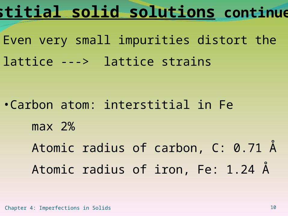
Even very small impurities distort the lattice ---> lattice
strains
•Carbon atom: interstitial in Fe
max 2%
Atomic radius of carbon, C: 0.71 Å
Atomic radius of iron, Fe: 1.24 Å
Interstitial solid solutions continue….

Chapter 4: Imperfections in Solids 11
Specification of composition
A and B atoms
A of weight atomic :A
A of mass :m)
Am+
Am(
Am
=A % Atom
mass / weight m,100×) m+(m
m =A Wt%
A
A
B
B
A
A
A
A
BA
A

Chapter 4: Imperfections in Solids 12
Dislocations- Line defects
• Edge dislocation
• Screw dislocation
Edge dislocation: Extra half plane of atoms
terminates within the crystal
•Dislocation line/extra half plane causes lattice to pull
apart.
•Where the extra half plane is not there, the lattice is
squeezed together

Chapter 4: Imperfections in Solids 13
Dislocations- Line defects
Screw dislocation:
•Shear stress to distort the lattice
•Upper region is shifted one atomic distance relative to
bottom
•Associated spiral or helical ramp
Mixed dislocation: Neither edge perpendicular () or
screw ( )

Chapter 4: Imperfections in Solids 14
Burger’s vector
Close-failure of a dislocation, b (extent of distortion).
Dislocation and b are perpendicular in edge. They are
parallel in screw. Extra half plane of atomsb: Burger’s vector: Edge Dislocation

Chapter 4: Imperfections in Solids 15
Source: William Callister 7th edition, chapter 4, page 91
Burger’s vector: Continue…
Edge Dislocation
Screw Dislocation
b points in a closed-packed direction and is equal to atomic spacing(s)

Chapter 4: Imperfections in Solids 16
Grain boundaries
•Grain boundaries are regions of impurity concentration
•Light mismatch between grains: small angle grain boundarye.g., tilt boundary •Grain within a grain: sub-grain; sub-grain boundary

Chapter 4: Imperfections in Solids 17
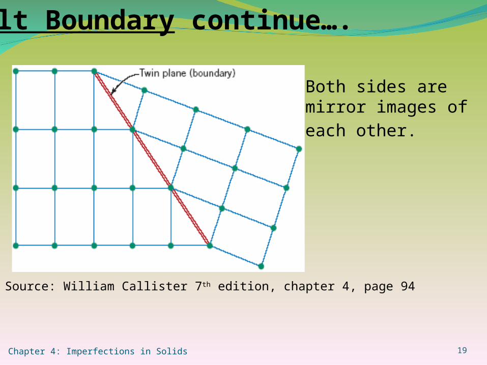
Twin Boundary:
Across a grain: mirror-lattice symmetry
•Due to atomic displacement from applied shear forces.
e.g., mechanical twins seen in BCC, HCP
•Due to annealing after deformation.
e.g., annealing twins seen mostly in FCC

Chapter 4: Imperfections in Solids 18
Tilt Boundary
Edge dislocation
Series of edge
dislocations
•Array of edge
dislocations.
•Similar to small
angle grain boundary
Source: William Callister 7th edition, chapter 4, page 94
Chapter 4: Imperfections in Solids 19
Both sides are mirror
images of each other.
Source: William Callister 7th edition, chapter 4, page 94
Tilt Boundary continue….

Chapter 4: Imperfections in Solids 20
Pores
Cracks
Inclusions
Other phases
Volume defects

Chapter 4: Imperfections in Solids 21
Microscopy: Macro/Microstructure photomicrographs
Optical/light microcopy: 2000x
Transmission electron microscopy: 1,000,000X, very thin
foil; fluorescent screen
Scanning electron microscopy: 50,000X, good depth of
field
Scanning Probe: 3D topography 109 X possible
Microscopy

Chapter 4: Imperfections in Solids 22
Grain size
ASTM grain size number
N = 2n-1
n = grain size number
N = Average No. of grain/square inch at 100X
Larger grain size number Smaller grains

Chapter 4: Imperfections in Solids 23
Summary Point defectsLine defects•Dislocation edge Screw
MixedVolume defects
High angleGrain boundary Low angle
TwinMicroscopy Grain Size