Embed Size (px)
Citation preview

1
6.0
Drawings for Electrical Systems
2
6.0
It’s an easily used software programme
for designing and estimating
electrical systems for residential and
service industry applications
What is GWCAD for?What is GWCAD for?

3
6.0
It enables installers and
designers to produce:
- location plan drawings of the building part
- drawings of the electrical system
- a distribution layout (including accessories)
- calculate lighting requirements
- a list of materials
What does GWCAD provide?What does GWCAD provide?

4
6.0
• This is a programme that works independently (AutoCAD not required)
• The programme has a two-dimensional CAD engine with all the main AutoCAD commands (layer, grid, filters, block management, etc.)
• It is possible to import and generate “dwg” and “dxf” files
• Drawings and images in the usual formats (bmp, jpg, wmf, etc.) can be imported and used for designing the system
GENERAL FEATURES

5
6.0MENU BARTOOL BAR
The programme’s commands are in the various drop-down menus of the “Menu bar”.
Some commands (the main ones) are available at the icons beneath the menu bar and to the left of the worksheet. These icons are all in the “Tool Bar”.

6
6.0
The various “Tool Bars” available can be put on display by going to the Tool Bar command in the menu “File/Preferences”.
TOOL BAR
7
6.0
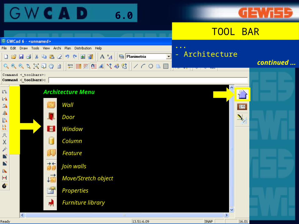
Architecture Menu
Wall
Door
Window
Column
Join walls
Move/Stretch object
Properties
...- Architecture
continued ...
TOOL BAR
Furniture library
Feature

8
6.0
ElectricalMenu
...- Electrical
Configure composition
Close composition
Device properties
Explode composition
Number boxes
Draw distributionAdd distribution accessories
Marker
Lighting calculation
Symbols list
Bill
TOOL BAR
Composition photo
Graphic composition
Electrical libraries
9
6.0
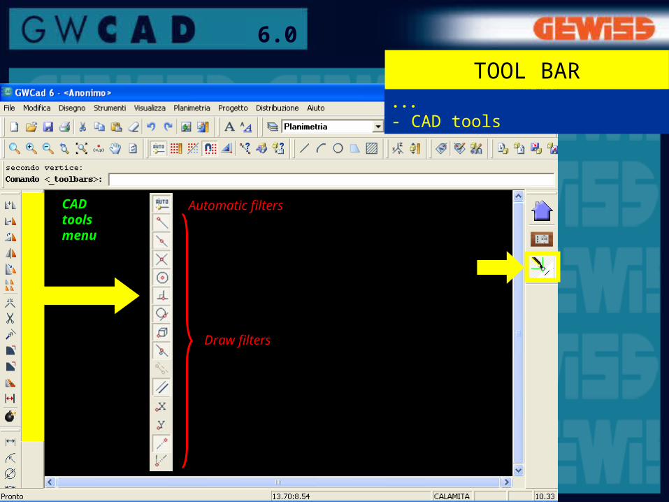
CADtoolsmenu
...- CAD tools
Draw filters
TOOL BAR
Automatic filters

10
6.0
COMMANDS BAR
Example: after having clicked on the icon “Wall”, you can:- draw the “Starting point” of the wall, or- click on “Arch wall” to draw an “Arch wall”, or- click on “Properties” (the window “Wall properties” appears)
COMMANDS BAR: after having launched a command (clicking on the icon or using the menu bar), messages appear in the Commands Bar representing requests for operations or parameters that the programme is expecting.The various possibilities are separated by “/”, and to select one, just click on it.

11
6.0
On starting up GWCAD, it is possible to adjust the worksheet by choosing:• format;• direction of the worksheet;• scale;• measuring unit.
SETTINGSCALE AND PAGE
12
6.0
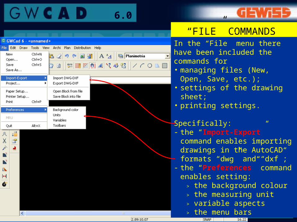
“FILE” COMMANDS In the “File” menu there have been included the commands for• managing files (New, Open,
Save, etc.);• settings of the drawing sheet;• printing settings.
Specifically:- the “Import-Export”
command enables importing drawings in the AutoCAD formats “dwg” and “dxf”;
- the “Preferences” command enables setting:
> the background colour> the measuring unit> variable aspects> the menu bars
13
6.0
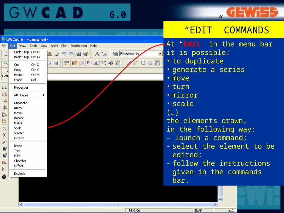
At “Edit” in the menu bar it is possible:• to duplicate• generate a series• move• turn• mirror• scale(…)the elements drawn, in the following way:- launch a command;- select the element to be
edited;- follow the instructions given
in the commands bar.
“EDIT” COMMANDS
14
6.0
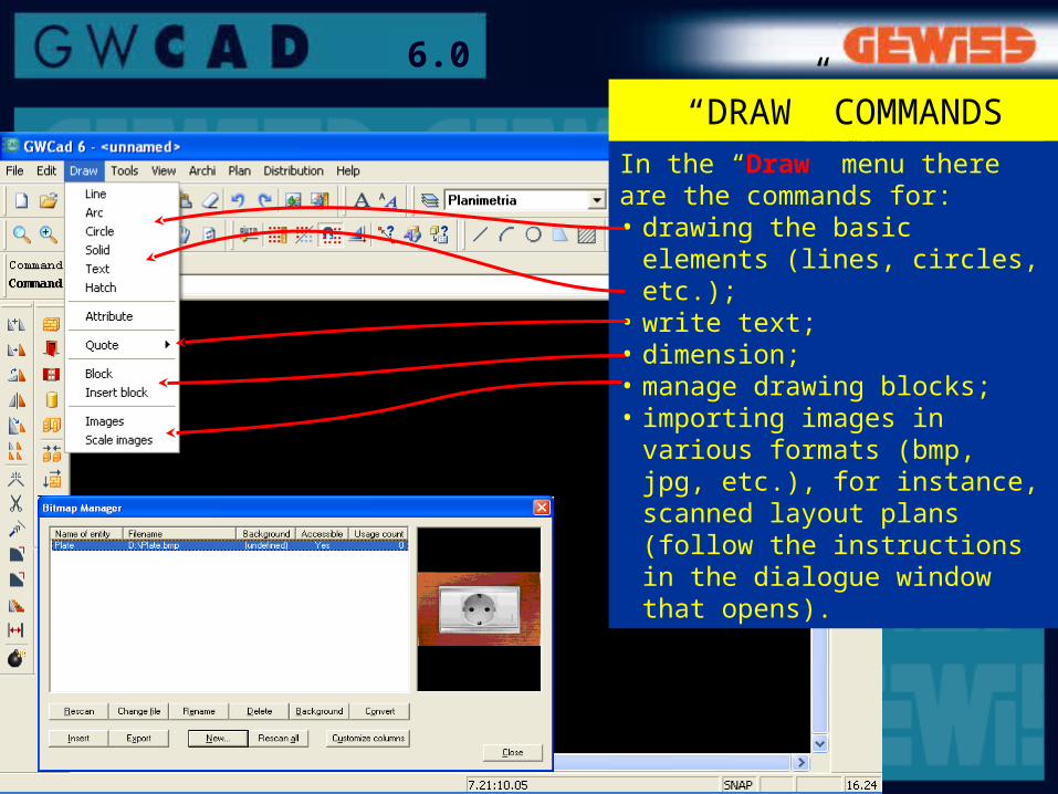
In the “Draw” menu there are the commands for:• drawing the basic elements
(lines, circles, etc.);• write text;• dimension;• manage drawing blocks;• importing images in various
formats (bmp, jpg, etc.), for instance, scanned layout plans (follow the instructions in the dialogue window that opens).
“DRAW” COMMANDS

15
6.0
In “Tools” there are various commands:• management of styles;• filters for precision drawing.
In detail:continued...
“TOOLS” COMMANDS

16
6.0
…
• the “Ortho” command is for drawing and shifting elements vertically or horizontally;
• with the “Textstyle” command, the text can be differentiated using Windows fonts
“TOOLS” COMMANDS

17
6.0
In “View” there are various commands for displaying the drawing.
Specifically:• the “Zoom” command is for
enlarging a detail in the drawing, and is used by:- launching the command;- click on the upper-left
corner of the detail to be enlarged;
- click on the lower-right corner of the detail to be enlarged,
• the command “Zoom Extension” is for seeing the whole drawing on the screen
“VIEW” COMMANDS
18
6.0
Symbols library
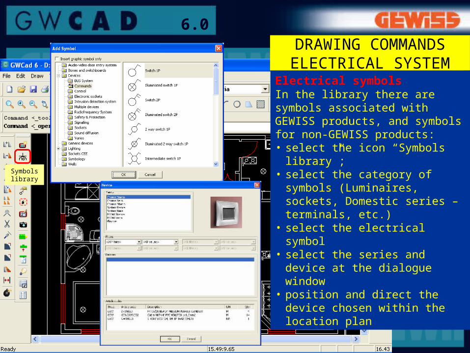
DRAWING COMMANDS ELECTRICAL SYSTEM
Electrical symbolsIn the library there are symbols associated with GEWISS products, and symbols for non-GEWISS products:• select the icon “Symbols
library”;• select the category of symbols
(Luminaires, sockets, Domestic series – terminals, etc.)
• select the electrical symbol• select the series and device at
the dialogue window• position and direct the device
chosen within the location plan
19
6.0
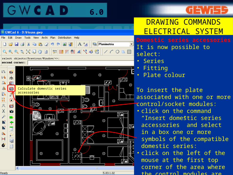
Domestic series accessoriesIt is now possible to select:• Series• Fitting• Plate colour
To insert the plate associated with one or more control/socket modules:• click on the command “Insert
domestic series accessories” and select in a box one or more symbols of the compatible domestic series:
• click on the left of the mouse at the first top corner of the area where the control modules are present;
continued...
DRAWING COMMANDS ELECTRICAL SYSTEM
Calculate domestic series accessories
20
6.0
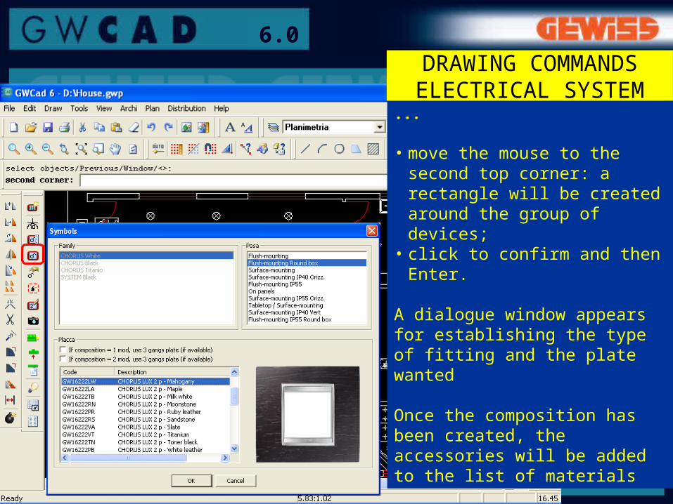
...
• move the mouse to the second top corner: a rectangle will be created around the group of devices;
• click to confirm and then Enter.
A dialogue window appears for establishing the type of fitting and the plate wanted
Once the composition has been created, the accessories will be added to the list of materials
DRAWING COMMANDS ELECTRICAL SYSTEM

21
6.0
Composition photo
With this button is possible to export the images of the compositions (Devices + Plates) and insert them into the project.
Clicking on this button and chosing the composition you can save the picture
Composition photo
DRAWING COMMANDS ELECTRICAL SYSTEM
22
6.0
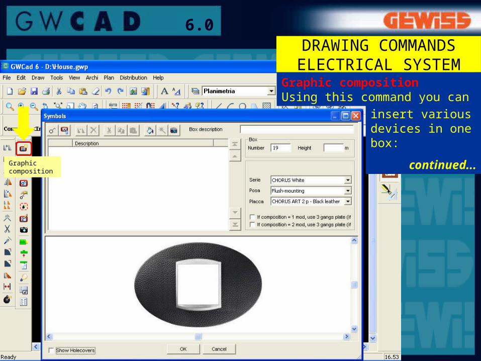
Graphic compositionUsing this command you can
Graphic composition
insert various devices in one box:
continued...
DRAWING COMMANDS ELECTRICAL SYSTEM

23
6.0
Devices commands
Range select
Laying select
Plate selectDevices layout
DRAWING COMMANDS ELECTRICAL SYSTEM

24
6.0
Further commands relating to the Domestic series
Device properties: for changing the type of device inserted
Explode composition: for cancelling the operation for calculating domestic series accessories so as to return to the original devices without accessories
Number boxes: to number the boxes and get a list of components in which there is the reference to the box they come from
continued...
Number boxes
Explode composition
Device properties
DRAWING COMMANDS ELECTRICAL SYSTEM

25
6.0
Defining symbols scale
The command Set composition makes it possible to set a scale for all the symbols, so that they can be inserted proportionally into an imported location plan (for instance). The symbols can be larger or smaller, increasing and decreasing the amount in the “Correction factor for fixed blocks”.
DRAWING COMMANDS ELECTRICAL SYSTEM
Configure composition
26
6.0
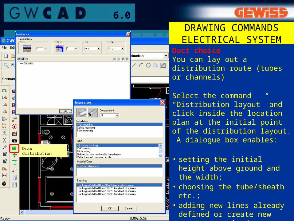
Duct choiceYou can lay out a distribution route (tubes or channels)
Select the command “Distribution layout” and click inside the location plan at the initial point of the distribution layout. A dialogue box enables:
• setting the initial height above ground and the width;
• choosing the tube/sheath etc.;• adding new lines already
defined or create new ones as required.
Draw distribution
DRAWING COMMANDS ELECTRICAL SYSTEM
27
6.0
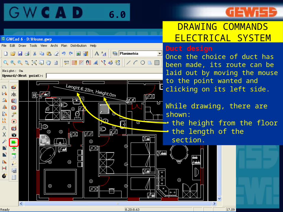
Duct designOnce the choice of duct has been made, its route can be laid out by moving the mouse to the point wanted and clicking on its left side.
While drawing, there are shown:• the height from the floor• the length of the section.
DRAWING COMMANDS ELECTRICAL SYSTEM
28
6.0
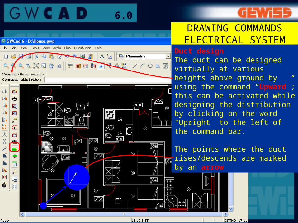
Duct designThe duct can be designed virtually at various heights above ground by using the command “Upward”; this can be activated while designing the distribution by clicking on the word “Upright” to the left of the command bar.
The points where the duct rises/descends are marked by an arrow
DRAWING COMMANDS ELECTRICAL SYSTEM
29
6.0
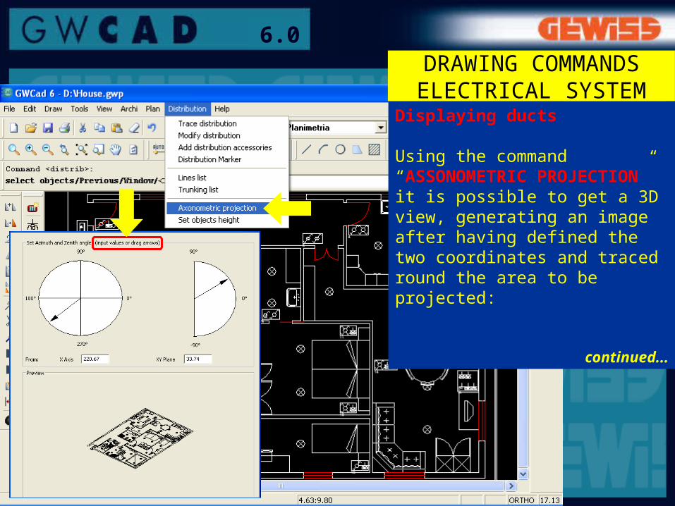
Displaying ducts
Using the command “ASSONOMETRIC PROJECTION” it is possible to get a 3D view, generating an image after having defined the two coordinates and traced round the area to be projected:
continued...
DRAWING COMMANDS ELECTRICAL SYSTEM
30
6.0DRAWING COMMANDS ELECTRICAL SYSTEM
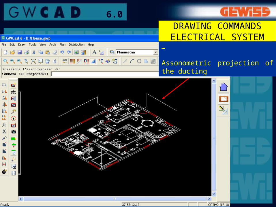
…
Assonometric projection of the ducting

31
6.0
Add distribution accessories
DRAWING COMMANDS ELECTRICAL SYSTEM
Distribution accessories This command is for selecting and adding accessories to the distribution system inserted (tubes or channels).The programme only offers the accessories compatible with the type of channel/tube selected.
Operating the command:• click on the specific
command• click on the channel (or
tube)• click on the quantity and set
the amount

32
6.0DRAWING COMMANDS ELECTRICAL SYSTEM
Lighting calculationThis can be done in two ways. METHOD 1:devices > illuminationAfter having inserted the luminaires, select the command “Lighting calculation”:• select the area of interest
(with a double click at its top corners or clicking inside it)
• a dialogue window will open – shown here – which gives the results of the lighting requirement values
continued...Lightingcalculation

33
6.0
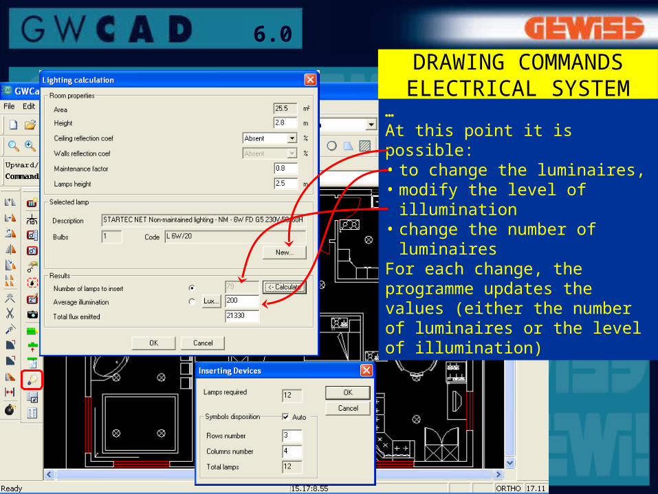
…
At this point it is possible:• to change the luminaires,• modify the level of
illumination• change the number of
luminairesFor each change, the programme updates the values (either the number of luminaires or the level of illumination)
continued...
DRAWING COMMANDS ELECTRICAL SYSTEM
34
6.0
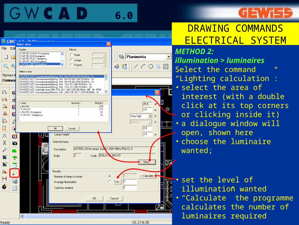
METHOD 2:illumination > luminairesSelect the command “Lighting calculation”:• select the area of interest
(with a double click at its top corners or clicking inside it)
• a dialogue window will open, shown here
• choose the luminaire wanted;
• set the level of illumination wanted
• “Calculate” the programme calculates the number of luminaires required
continued...
DRAWING COMMANDS ELECTRICAL SYSTEM
35
6.0
…At this point it is possible:• to change the luminaires,• modify the level of
illumination• change the number of
luminairesFor each change, the programme updates the values (either the number of luminaires or the level of illumination)
DRAWING COMMANDS ELECTRICAL SYSTEM
36
6.0LIST OF MATERIALS
QUANTITIES ESTIMATE
Bill
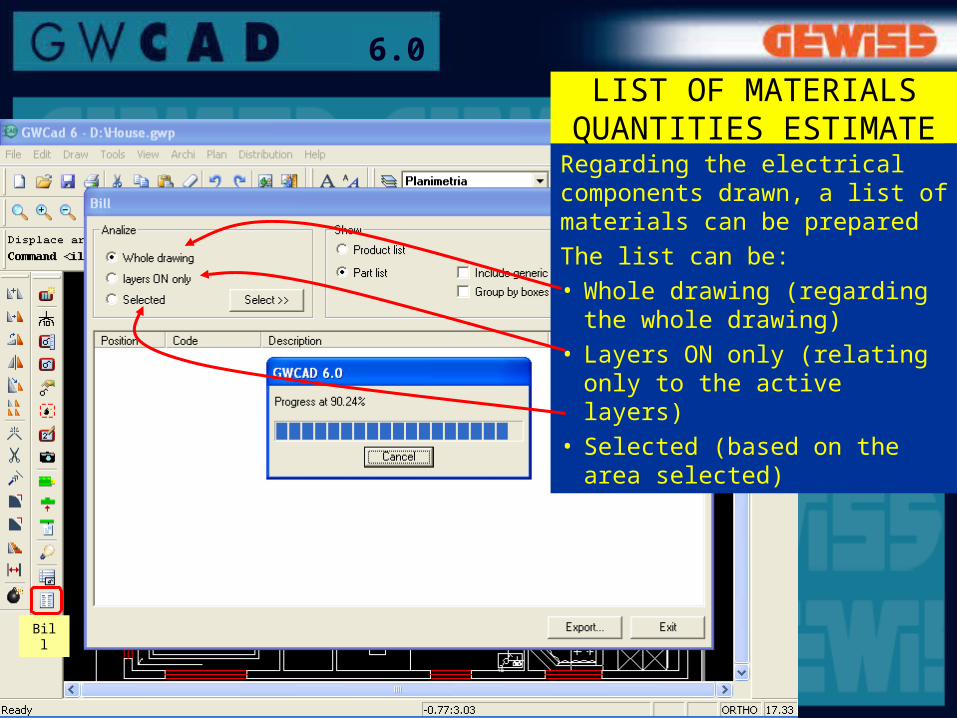
Regarding the electrical components drawn, a list of materials can be preparedThe list can be:• Whole drawing (regarding the
whole drawing)• Layers ON only (relating only
to the active layers)• Selected (based on the area
selected)

37
6.0LIST OF MATERIALS
QUANTITIES ESTIMATERegarding the components in the domestic series:• in the list of materials it can
be decided to take account of the cables and tubes that the programme automatically inserts in the composition;
• the various components can be grouped by box, so as to have for each element the reference to the composition.

38
6.0
The list of materials can be:• printed• saved to file in text format
(txt)• saved to file to be processed
by the programme “GWPRICE”
LIST OF MATERIALSQUANTITIES ESTIMATE

39
6.0
Marker:for each distribution layout, the identity data for the duct can be included in the drawing
KEYS ANDIDENTIFIERS
Symbols list: it is possible to insert in the drawing the key to the symbols used in the electrical diagram
Marker
Symbols list
40
6.0
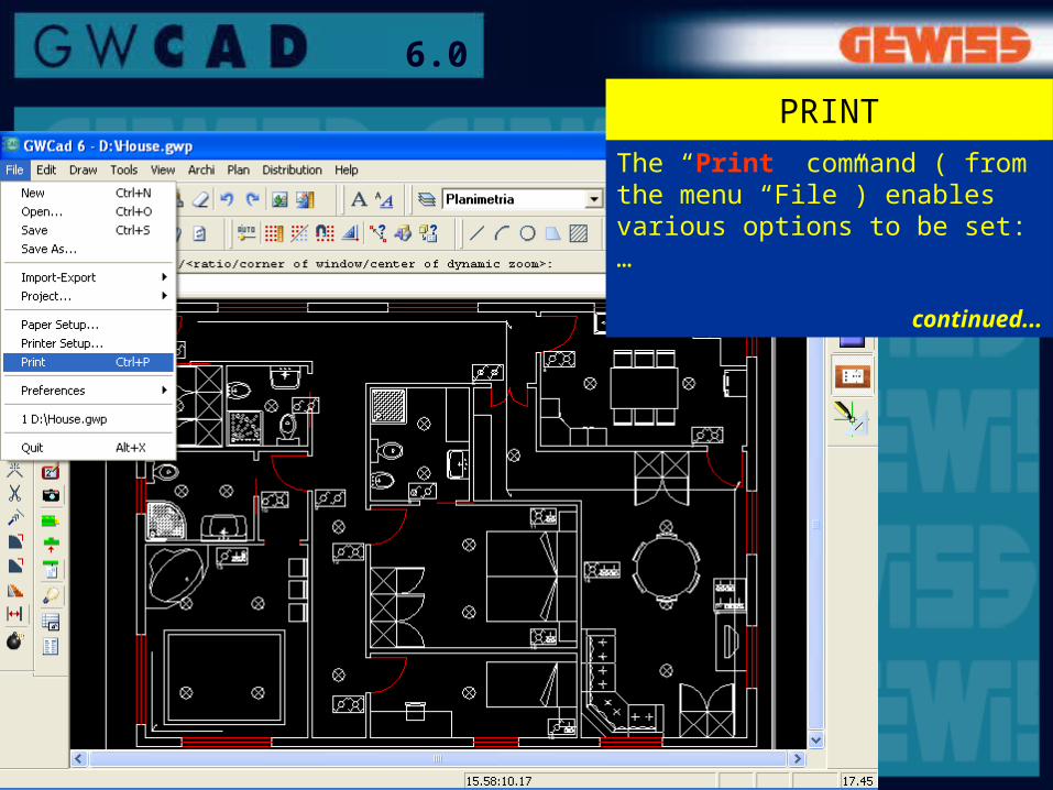
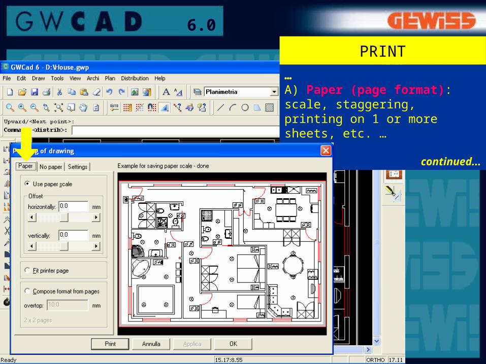
The “Print” command ( from the menu “File”) enables various options to be set:…
continued...
41
6.0
… A) Paper (page format): scale, staggering, printing on 1 or more sheets, etc. …
continued...
42
6.0
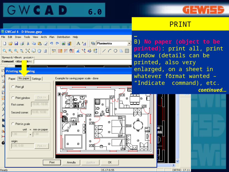
PRINT…B) No paper (object to be printed): print all, print window (details can be printed, also very enlarged, on a sheet in whatever format wanted – “Indicate” command), etc.
continued...

43
6.0
PRINT…C) Setting (to set page and printer): margins, conversion colours-thickness, printer settings, etc.
continued...

44
6.0
MANUAL
Within GWCAD (“Help GWCAD” command) there is a Manual available in which all the functions and commands in the programme are explained.This manual, in “pdf” format, can be viewed on screen or printed