Embed Size (px)
Citation preview
8/8/2019 1 4-Boolean Algebra
http://slidepdf.com/reader/full/1-4-boolean-algebra 1/79
Slide 2/78Boolean Algebra and Logic Circuits
Learning Objectives
In this chapter you will learn about:
§ Boolean algebra
§ Fundamental concepts and basic laws of Boolean
algebra§ Boolean function and minimization
§ Logic gates
§ Logic circuits and Boolean expressions
§ Combinational circuits and design
60
8/8/2019 1 4-Boolean Algebra
http://slidepdf.com/reader/full/1-4-boolean-algebra 2/79
Slide 3/78Boolean Algebra and Logic Circuits
§
§
Simplifying representation
Manipulation of propositional logic
§ In 1938, Claude E. Shannon proposed using Boolean algebra indesign of relay switching circuits
§ Provides economical and straightforward approach
§ Used extensively in designing electronic circuits used in computers
Boolean Algebra
§ An algebra that deals with binary number system
§ George Boole (1815-1864), an English mathematician, developed
it for:
60

8/8/2019 1 4-Boolean Algebra
http://slidepdf.com/reader/full/1-4-boolean-algebra 3/79
Slide 4/78Boolean Algebra and Logic Circuits
Fundamental Concepts of Boolean Algebra
§ Use of Binary Digit
§ Boolean equations can have either of two possible
values, 0 and 1
§ Logical Addition
§ Symbol µ+¶, also known as µOR ¶ operator, used for
logical addition. Follows law of binary addition
§ Logical Multiplication
§ Symbol µ.¶, also known as µAND¶ operator, used for
logical multiplication. Follows law of binary
multiplication
§ Complementation§ Symbol µ-¶, also known as µNOT¶ operator, used for
complementation. Follows law of binary compliment
61

8/8/2019 1 4-Boolean Algebra
http://slidepdf.com/reader/full/1-4-boolean-algebra 4/79
Slide 5/78Boolean Algebra and Logic Circuits
Operator Precedence
§ Each operator has a precedence level
§ Higher the operator ¶s precedence level, earlier it is evaluated
§ Expression is scanned from left to right
§ First, expressions enclosed within parentheses are evaluated
§ Then, all complement (NOT) operations are performed
§ Then, all µ.¶ (AND) operations are performed
§ Finally, all µ¶ (OR) operations are performed
(Continued on next slide)
62

8/8/2019 1 4-Boolean Algebra
http://slidepdf.com/reader/full/1-4-boolean-algebra 5/79
Slide 6/78Boolean Algebra and Logic Circuits
1st2nd 3rd
Operator Precedence
(Continued from previous slide..)
X Y Z
62
8/8/2019 1 4-Boolean Algebra
http://slidepdf.com/reader/full/1-4-boolean-algebra 6/79
Slide 7/78Boolean Algebra and Logic Circuits
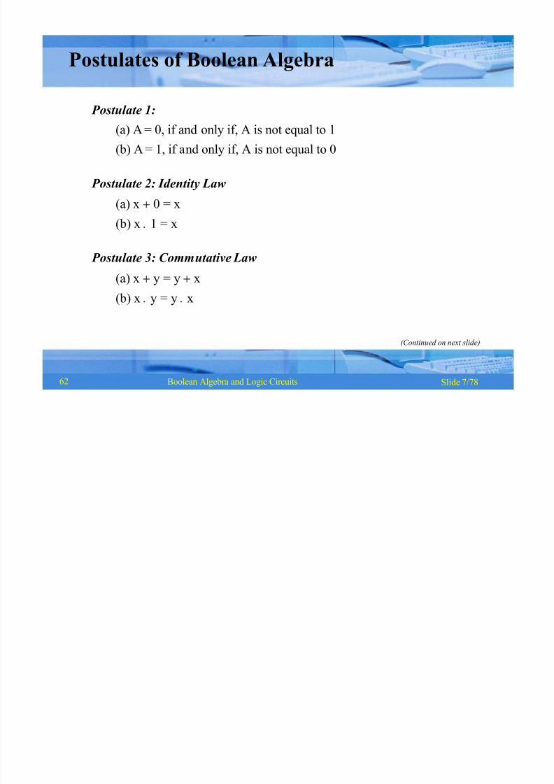
Postulates of Boolean Algebra
Postulate 1:
(a) A = 0, if and only if, A is not equal to 1
(b) A = 1, if and only if, A is not equal to 0
Postulate 2: Identity Law
(a) x 0 = x
(b) x 1 = x
Postulate 3: Commutative Law
(a) x y = y x
(b) x y = y x
(Continued on next slide)
62

8/8/2019 1 4-Boolean Algebra
http://slidepdf.com/reader/full/1-4-boolean-algebra 7/79
Slide 8/78Boolean Algebra and Logic Circuits
Postulates of Boolean Algebra
(Continued from previous slide..)
Postulate 4: Associative Law
(a) x (y z) = (x y) z
(b) x (y z) = (x y) z
Postulate 5: Distributive Law(a) x (y z) = (x y) (x z)
(b) x (y z) = (x y) (x z)
Postulate 6: Inverse Law
(a) x x = 1
(b) x x = 0
62
8/8/2019 1 4-Boolean Algebra
http://slidepdf.com/reader/full/1-4-boolean-algebra 8/79
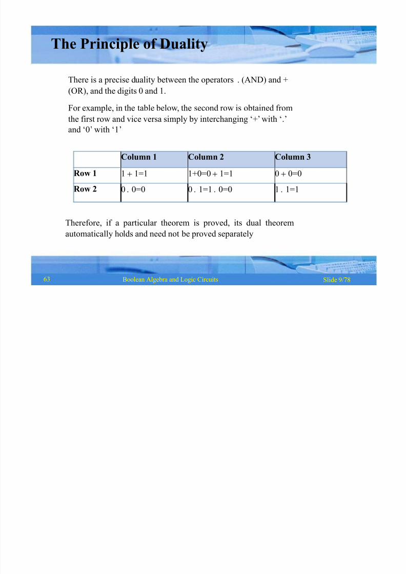
Column 1 Column 2 Column 3
Row 1 1 1=1 1+0=0 1=1 0 0=0
Row 2 0 0=0 0 1=1 0=0 1 1=1
Slide 9/78Boolean Algebra and Logic Circuits
The Principle of Duality
There is a precise duality between the operators . (AND) and +
(OR), and the digits 0 and 1.
For example, in the table below, the second row is obtained from
the first row and vice versa simply by interchanging µ+¶with µ.¶
and µ0¶with µ1¶
Therefore, if a particular theorem is proved, its dual theorem
automatically holds and need not be proved separately
63
8/8/2019 1 4-Boolean Algebra
http://slidepdf.com/reader/full/1-4-boolean-algebra 9/79
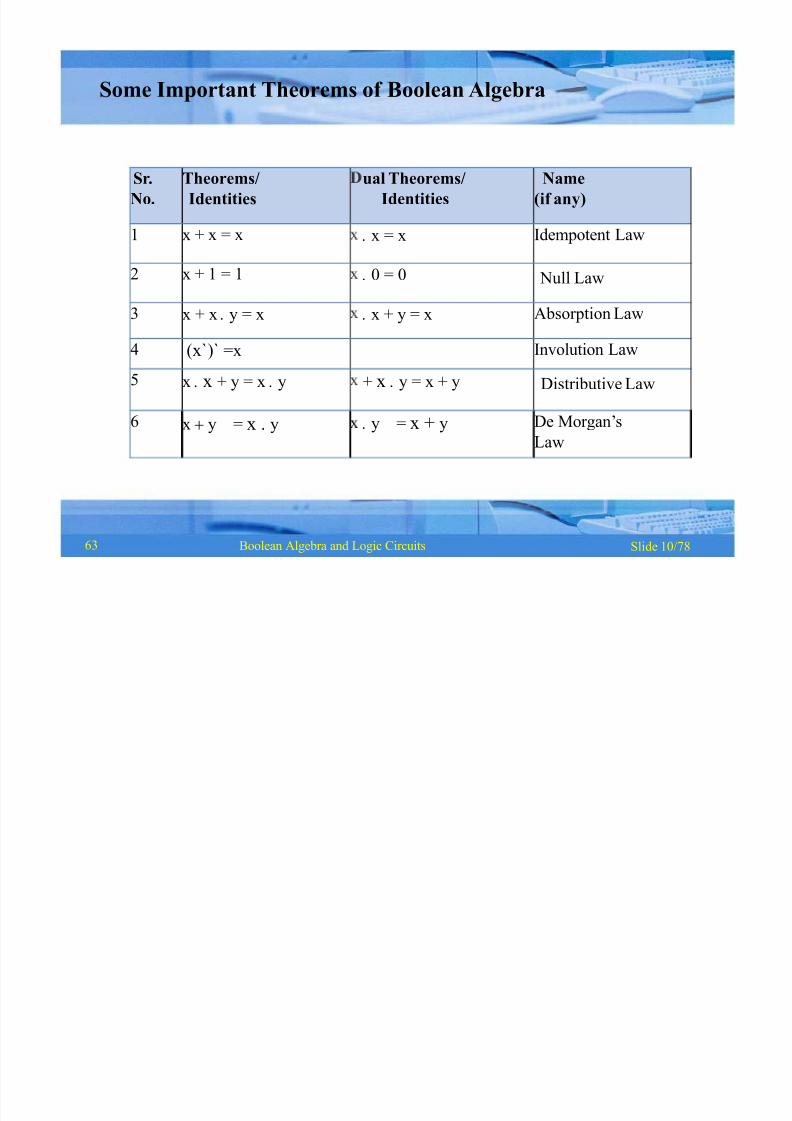
Sr.
No.
Theorems/
Identities
ual Theorems/
Identities
Name
(if any)
1 x + x = x x = x Idempotent Law
2 x + 1 = 1 0 = 0 Null Law
3 x + x y = x x + y = x Absorption Law
4 (x`)` =x Involution Law
5 x x + y = x y + x y = x + y Distributive Law
6 x y = x . y y = x + y De Morgan¶s
Law
Slide 10/78Boolean Algebra and Logic Circuits
Some Important Theorems of Boolean Algebra
63
8/8/2019 1 4-Boolean Algebra
http://slidepdf.com/reader/full/1-4-boolean-algebra 10/79
Slide 11/78Boolean Algebra and Logic Circuits
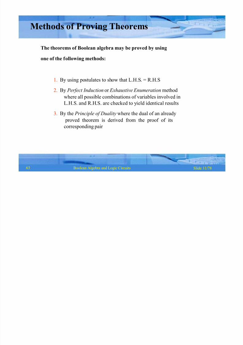
Methods of Proving Theorems
The theorems of Boolean algebra may be proved by using
one of the following methods:
1. By using postulates to show that L.H.S. = R.H.S
2. By P erfect Induction or Exhaustive Enumeration method
where all possible combinations of variables involved in
L.H.S. and R.H.S. are checked to yield identical results
3. By the P rinciple of Duality where the dual of an already
proved theorem is derived from the proof of its
corresponding pair
63
8/8/2019 1 4-Boolean Algebra
http://slidepdf.com/reader/full/1-4-boolean-algebra 11/79
Slide 12/78Boolean Algebra and Logic Circuits
by
by
by
by
by
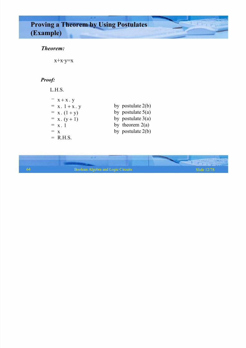
postulate 2(b)
postulate 5(a)
postulate 3(a)
theorem 2(a)
postulate 2(b)
=
=
=
=
=
=
=
x x y
x 1 x y
x (1 y)
x (y 1)
x 1
x
R.H.S.
Proving a Theorem by Using Postulates
(Example)
Theorem:
x+x·y=x
Proof:
L.H.S.
64

8/8/2019 1 4-Boolean Algebra
http://slidepdf.com/reader/full/1-4-boolean-algebra 12/79
y x y x x y
0 0 0 0
0 1 0 0
1 0 0 1
1 1 1 1
Slide 13/78Boolean Algebra and Logic Circuits
Proving a Theorem by Perfect Induction
(Example)
Theorem:
x + x ·y = x
=
64

8/8/2019 1 4-Boolean Algebra
http://slidepdf.com/reader/full/1-4-boolean-algebra 13/79
Slide 14/78Boolean Algebra and Logic Circuits
by
by
by
by
by
postulate
postulate
postulate
postulate
postulate
2(b)
6(a)
5(b)
6(b)
2(a)
L.H.S.=x x
= (x x) 1
= (x x) (x +X)
= x x X
=x 0=x
= R.H.S.
Proving a Theorem by the
Principle of Duality (Example)
Theorem:
x+x=x
Proof:
(Continued on next slide)
63

8/8/2019 1 4-Boolean Algebra
http://slidepdf.com/reader/full/1-4-boolean-algebra 14/79
Slide 15/78Boolean Algebra and Logic Circuits
by
by
by
by
by
postulate
postulate
postulate
postulate
postulate
2(a)
6(b)
5(a)
6(a)
2(b)
L.H.S.
=x x
=x x 0
= x x x X
= x (x + X )
=x 1
=x= R.H.S.
Notice that each step of
the proof of the dual
theorem is derived from
the proof of itscorresponding pair in
the original theorem
Proving a Theorem by the
Principle of Duality (Example)(Continued from previous slide..)
Dual Theorem:
x x=x
Proof:
63
8/8/2019 1 4-Boolean Algebra
http://slidepdf.com/reader/full/1-4-boolean-algebra 15/79
Slide 7/78Boolean Algebra and Logic Circuits62
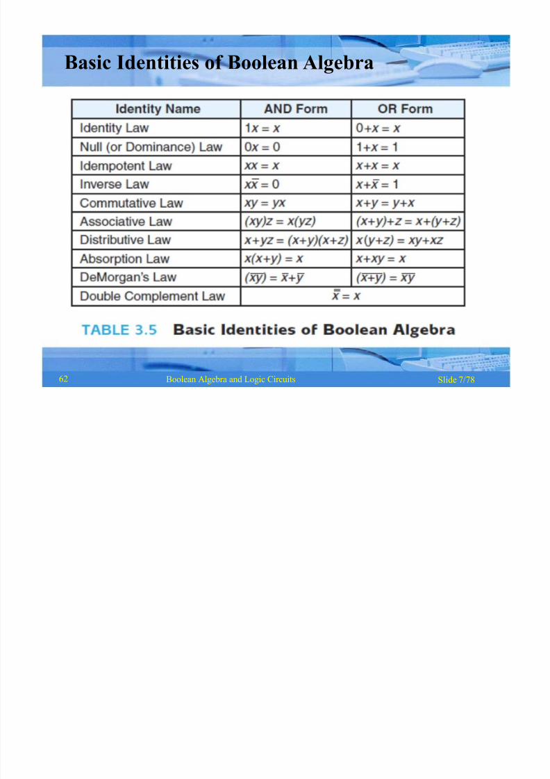
Basic Identities of Boolean Algebra
8/8/2019 1 4-Boolean Algebra
http://slidepdf.com/reader/full/1-4-boolean-algebra 16/79
Slide 7/78Boolean Algebra and Logic Circuits62
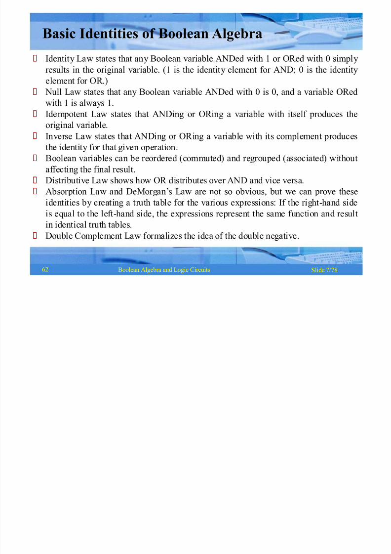
Basic Identities of Boolean Algebra
Identity Law states that any Boolean variable ANDed with 1 or ORed with 0 simply
results in the original variable. (1 is the identity element for AND; 0 is the identityelement for OR.)
Null Law states that any Boolean variable ANDed with 0 is 0, and a variable ORed
with 1 is always 1.
Idempotent Law states that ANDing or ORing a variable with itself produces the
original variable.
Inverse Law states that ANDing or ORing a variable with its complement producesthe identity for that given operation.
Boolean variables can be reordered (commuted) and regrouped (associated) without
affecting the final result.
Distributive Law shows how OR distributes over AND and vice versa.
Absorption Law and DeMorgan¶s Law are not so obvious, but we can prove these
identities by creating a truth table for the various expressions: If the right-hand sideis equal to the left-hand side, the expressions represent the same function and result
in identical truth tables.
Double Complement Law formalizes the idea of the double negative.
8/8/2019 1 4-Boolean Algebra
http://slidepdf.com/reader/full/1-4-boolean-algebra 17/79
Slide 16/78Boolean Algebra and Logic Circuits
Boolean Functions
§ A Boolean function is an expression formed with:
§ Binary variables
§ Operators (OR, AND, and NOT)
§ Parentheses, and equal sign
§ The value of a Boolean function can be either 0 or 1
§ A Boolean function may be represented as:
§ An algebraic expression, or
§ A truth table
67
8/8/2019 1 4-Boolean Algebra
http://slidepdf.com/reader/full/1-4-boolean-algebra 18/79
Slide 17/78Boolean Algebra and Logic Circuits
Representation as an
Algebraic Expression
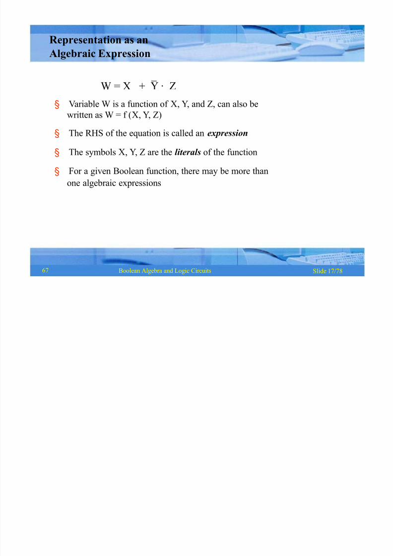
W = X + Y · Z
§ Variable W is a function of X,Y, and Z, can also be
written as W = f (X,Y, Z)
§ The RHS of the equation is called an expression
§ The symbols X, Y, Z are the literals of the function
§ For a given Boolean function, there may be more than
one algebraic expressions
67

8/8/2019 1 4-Boolean Algebra
http://slidepdf.com/reader/full/1-4-boolean-algebra 19/79
X Y Z
0 0 0 0
0 0 1 1
0 1 0 0
0 1 1 0
1 0 0 1
1 0 1 1
1 1 0 1
1 1 1 1
Slide 18/78Boolean Algebra and Logic Circuits
Representation as a Truth Table
(Continued on next slide)
67

8/8/2019 1 4-Boolean Algebra
http://slidepdf.com/reader/full/1-4-boolean-algebra 20/79
Slide 19/78Boolean Algebra and Logic Circuits
Representation as a Truth Table
(Continued from previous slide..)
§ The number of rows in the table is equal to 2n, where
n is the number of literals in the function
§ The combinations of 0s and 1s for rows of this table
are obtained from the binary numbers by counting
from 0 to 2n - 1
67

8/8/2019 1 4-Boolean Algebra
http://slidepdf.com/reader/full/1-4-boolean-algebra 21/79
Slide 20/78Boolean Algebra and Logic Circuits
Minimization of Boolean Functions
§ Minimization of Boolean functions deals with
§ Reduction in number of literals
§ Reduction in number of terms
§ Minimization is achieved through manipulatingexpression to obtain equal and simpler expression(s)
(having fewer literals and/or terms)
(Continued on next slide)
68
8/8/2019 1 4-Boolean Algebra
http://slidepdf.com/reader/full/1-4-boolean-algebra 22/79
Slide 21/78Boolean Algebra and Logic Circuits
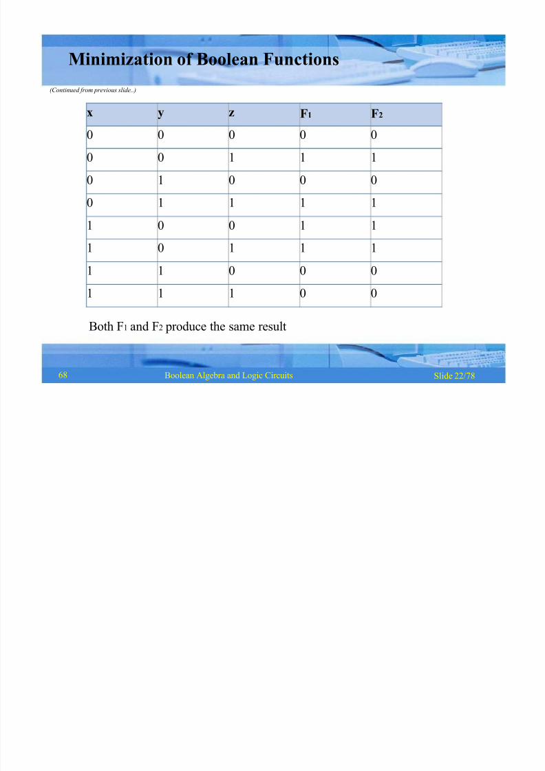
Minimization of Boolean Functions
(Continued from previous slide..)
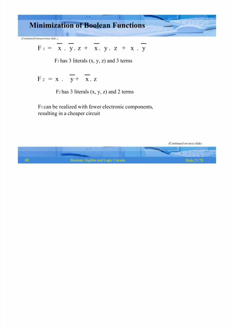
F 1 = x y z + x y z + x y
F1 has 3 literals (x, y, z) and 3 terms
F2
= x y + x zF2 has 3 literals (x, y, z) and 2 terms
F2 can be realized with fewer electronic components,
resulting in a cheaper circuit
(Continued on next slide)
68
8/8/2019 1 4-Boolean Algebra
http://slidepdf.com/reader/full/1-4-boolean-algebra 23/79
x y z F1 F2
0 0 0 0 0
0 0 1 1 1
0 1 0 0 0
0 1 1 1 1
1 0 0 1 1
1 0 1 1 1
1 1 0 0 0
1 1 1 0 0
Slide 22/78Boolean Algebra and Logic Circuits
Minimization of Boolean Functions
(Continued from previous slide..)
Both F1 and F2 produce the same result
68
8/8/2019 1 4-Boolean Algebra
http://slidepdf.com/reader/full/1-4-boolean-algebra 24/79
Slide 23/78Boolean Algebra and Logic Circuits
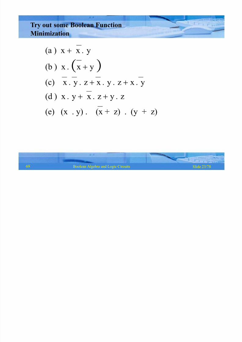
(a ) x x y
(b ) x x y
(c) x y z x y z x y(d ) x y x z y z
(e) (x . y) . (x + z) . (y + z)
Try out some Boolean Function
Minimization
69
8/8/2019 1 4-Boolean Algebra
http://slidepdf.com/reader/full/1-4-boolean-algebra 25/79
Slide 24/78Boolean Algebra and Logic Circuits
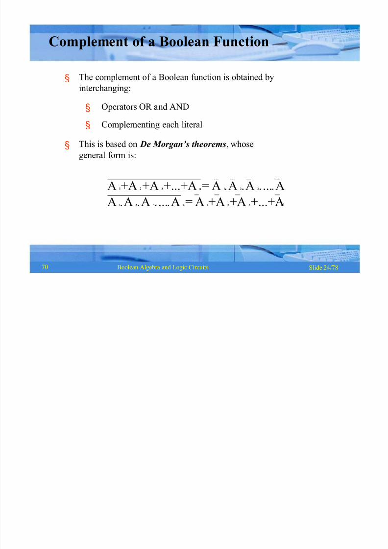
§ The complement of a Boolean function is obtained by
interchanging:
§
§
Operators OR and AND
Complementing each literal
§ This is based on De Morgan¶s t heorems, whose
general form is:
n
n
A 1+A 2+A 3+...+A n= A 1A 2A 3...A
A1
A2
A3
...An
= A1
+A2
+A3
+...+A
Complement of a Boolean Function
70

8/8/2019 1 4-Boolean Algebra
http://slidepdf.com/reader/full/1-4-boolean-algebra 26/79
Slide 25/78Boolean Algebra and Logic Circuits
Complementing a Boolean Function (Example)
F1= xyz+ x y z
To obtain F1 , we first interchange the OR and the ANDoperators giving
x+y +z x+y + z Now we complement each literal giving
1
71

8/8/2019 1 4-Boolean Algebra
http://slidepdf.com/reader/full/1-4-boolean-algebra 27/79
Slide 26/78Boolean Algebra and Logic Circuits
Minterms
Maxterms
: n variables forming an AND term, with
each variable being primed or unprimed,
provide 2n possible combinations called
minterms or standard products
: n variables forming an OR term, with
each variable being primed or unprimed,
provide 2n possible combinations called
maxterms or standard sums
Canonical Forms of Boolean Functions
71
8/8/2019 1 4-Boolean Algebra
http://slidepdf.com/reader/full/1-4-boolean-algebra 28/79
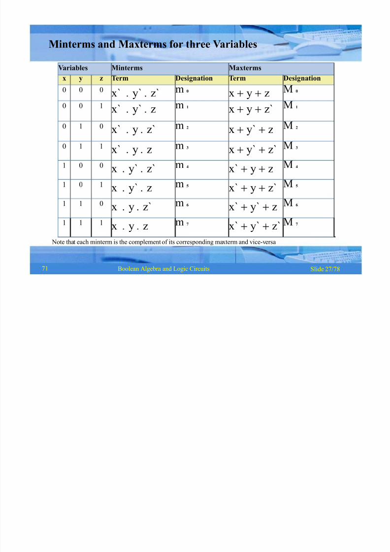
Variables Minterms Maxtermsx y z Term Designation Term Designation
0 0 0 x` y` z` m 0 x y z M 0
0 0 1 x` y` z m 1 x y z` M 1
0 1 0 x` y z` m 2 x y` z M 2
0 1 1 x` y z m 3 x y` z` M 3
1 0 0 x y` z` m 4 x` y z M 4
1 0 1 x y` z m 5 x` y z` M 5
1 1 0 x y z` m 6 x` y` z M 6
1 1 1 x y z m 7 x` y` z` M 7
Slide 27/78Boolean Algebra and Logic Circuits
Minterms and Maxterms for three Variables
Note that each minterm is the complement of its corresponding maxterm and vice-versa
71
8/8/2019 1 4-Boolean Algebra
http://slidepdf.com/reader/full/1-4-boolean-algebra 29/79
Slide 28/78Boolean Algebra and Logic Circuits
xx+ y z
xy + x y
x+ yx y+z
x y+x y z`
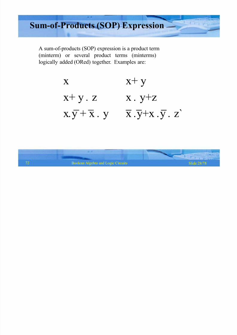
Sum-of -Products (SOP) Expression
A sum-of-products (SOP) expression is a product term
(minterm) or several product terms (minterms)
logically added (ORed) together. Examples are:
72

8/8/2019 1 4-Boolean Algebra
http://slidepdf.com/reader/full/1-4-boolean-algebra 30/79
Slide 29/78Boolean Algebra and Logic Circuits
Steps to Express a Boolean Function
in its Sum-of -Products Form
1. Construct a truth table for the given Boolean
function
2. Form a minterm for each combination of the
variables, which produces a 1 in the function
3. The desired expression is the sum (OR) of all the
minterms obtained in Step 2
72
8/8/2019 1 4-Boolean Algebra
http://slidepdf.com/reader/full/1-4-boolean-algebra 31/79
x y z F1
0 0 0 0
0 0 1 1
0 1 0 0
0 1 1 0
1 0 0 1
1 0 1 0
1 1 0 0
1 1 1 1
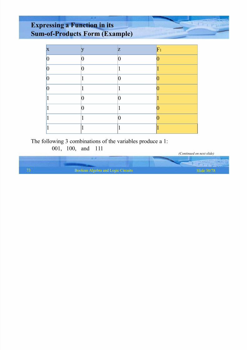
Slide 30/78Boolean Algebra and Logic Circuits
Expressing a Function in its
Sum-of -Products Form (Example)
The following 3 combinations of the variables produce a 1:
001, 100, and 111(Continued on next slide)
73
8/8/2019 1 4-Boolean Algebra
http://slidepdf.com/reader/full/1-4-boolean-algebra 32/79
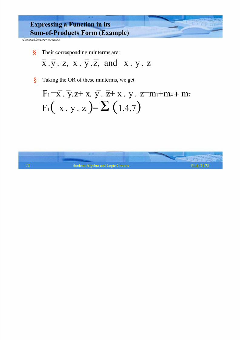
Slide 31/78Boolean Algebra and Logic Circuits
Expressing a Function in its
Sum-of -Products Form (Example)(Continued from previous slide..)
§ Their corresponding minterms are:
x y z, x y z, and x y z
§ Taking the OR of these minterms, we get
F1 =x yz+ xy z+ x y z=m1+m4 m7
F1x y z = 1,4,7
72
8/8/2019 1 4-Boolean Algebra
http://slidepdf.com/reader/full/1-4-boolean-algebra 33/79
Slide 32/78Boolean Algebra and Logic Circuits
x
x+ y
x+ y z
x+ y x+yx+ y x + yx+ y+z
x+ yx+ y
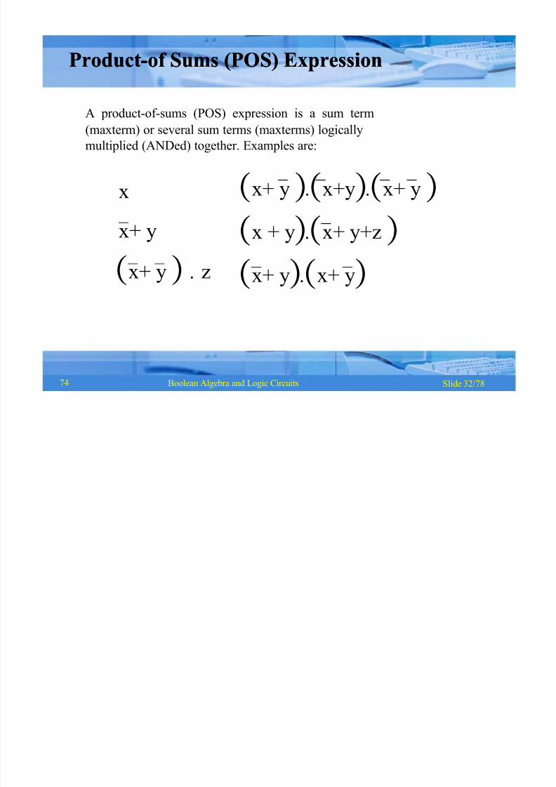
ProductProduct--of Sums (POS) Expressionof Sums (POS) Expression
A product-of-sums (POS) expression is a sum term
(maxterm) or several sum terms (maxterms) logically
multiplied (ANDed) together. Examples are:
74

8/8/2019 1 4-Boolean Algebra
http://slidepdf.com/reader/full/1-4-boolean-algebra 34/79
Slide 33/78Boolean Algebra and Logic Circuits
Steps to Express a Boolean Function
in its Product-of -Sums Form
1. Construct a truth table for the given Boolean function
2. Form a maxterm for each combination of the variables,
which produces a 0 in the function
3. The desired expression is the product (AND) of all the
maxterms obtained in Step 2
74
8/8/2019 1 4-Boolean Algebra
http://slidepdf.com/reader/full/1-4-boolean-algebra 35/79
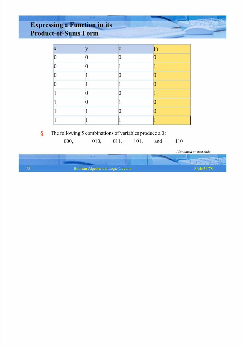
x y z F1
0 0 0 0
0 0 1 1
0 1 0 0
0 1 1 01 0 0 1
1 0 1 0
1 1 0 0
1 1 1 1
Slide 34/78Boolean Algebra and Logic Circuits
§ The following 5 combinations of variables produce a 0:
000, 010, 011, 101, and 110
Expressing a Function in its
Product-of -Sums Form
(Continued on next slide)
73
8/8/2019 1 4-Boolean Algebra
http://slidepdf.com/reader/full/1-4-boolean-algebra 36/79
Slide 35/78Boolean Algebra and Logic Circuits
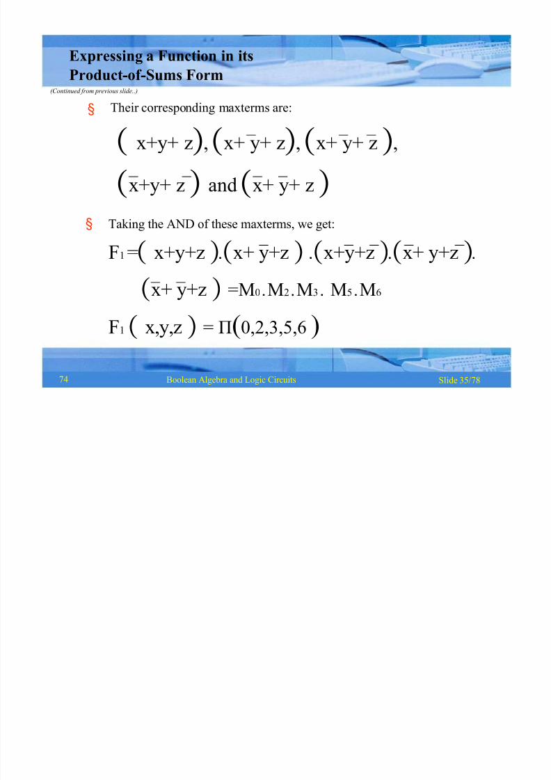
§
§
Their corresponding maxterms are:
x+y+ z, x+ y+ z, x+ y+ z ,
x+y+ z
and
x+ y+ z
Taking the AND of these maxterms, we get:
F1 =x+y+z x+ y+z x+y+z x+ y+z
x+ y+z =M0 M2 M3 M5 M6
F1 x,y,z = (0,2,3,5,6 )
Expressing a Function in its
Product-of -Sums Form(Continued from previous slide..)
74
8/8/2019 1 4-Boolean Algebra
http://slidepdf.com/reader/full/1-4-boolean-algebra 37/79
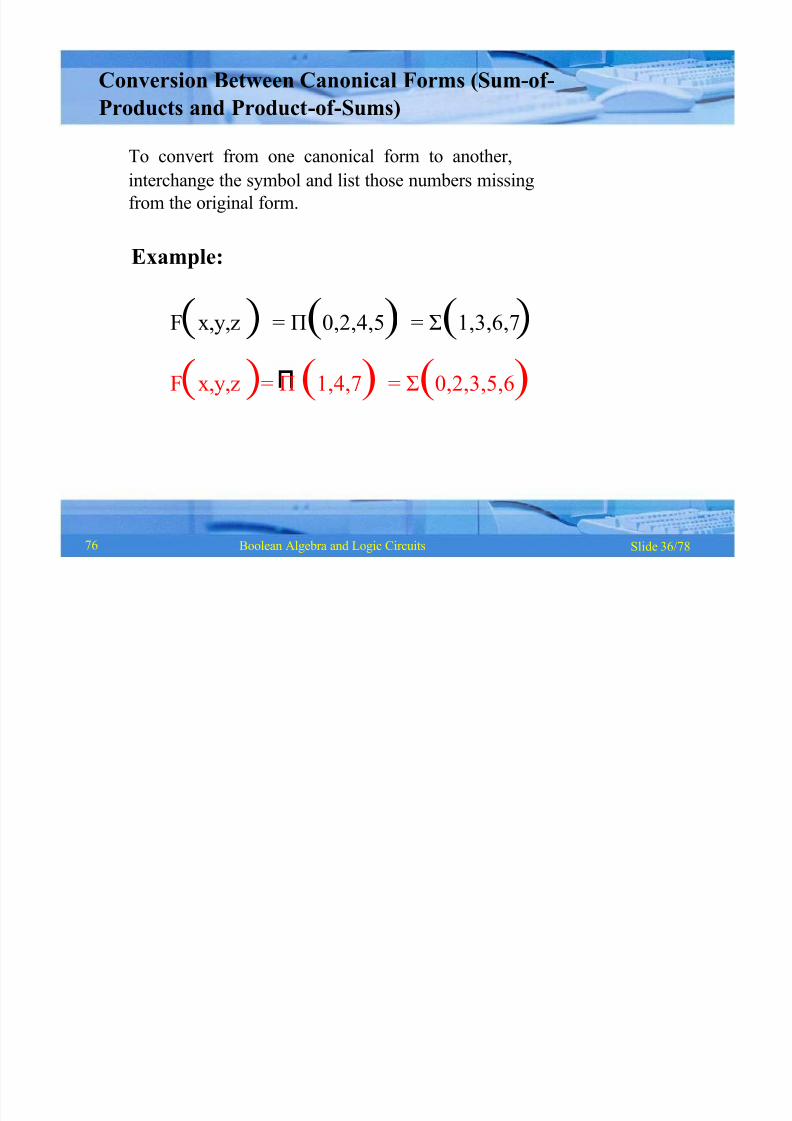
Slide 36/78Boolean Algebra and Logic Circuits
Fx,y,z = (0,2,4,5) = (1,3,6,7
Fx,y,z = (1,4,7) = (0,2,3,5,6)
Conversion Between Canonical Forms (Sum-of -
Products and Product-of -Sums)
To convert from one canonical form to another,
interchange the symbol and list those numbers missing
from the original form.
Example:
76

8/8/2019 1 4-Boolean Algebra
http://slidepdf.com/reader/full/1-4-boolean-algebra 38/79
Slide 37/78Boolean Algebra and Logic Circuits
Logic Gates
§ Logic gates are electronic circuits that operate on
one or more input signals to produce standard output
signal
§ Are the building blocks of all the circuits in a
computer
§ Some of the most basic and useful logic gates are
AND, OR, NOT, NAND and NOR gates
77
8/8/2019 1 4-Boolean Algebra
http://slidepdf.com/reader/full/1-4-boolean-algebra 39/79
Slide 38/78Boolean Algebra and Logic Circuits
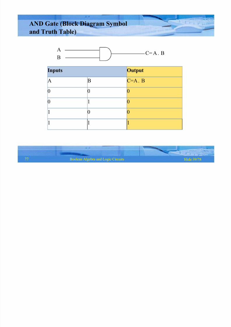
AND Gate
§ Physical realization of logical multiplication (AND)
operation
§ Generates an output signal of 1 only if all input
signals are also 1
77
8/8/2019 1 4-Boolean Algebra
http://slidepdf.com/reader/full/1-4-boolean-algebra 40/79
Inputs Output
A B C=A B
0 0 0
0 1 0
1 0 0
1 1 1
Slide 39/78Boolean Algebra and Logic Circuits
A
BC= A B
AND Gate (Block Diagram Symbol
and Truth Table)
77

8/8/2019 1 4-Boolean Algebra
http://slidepdf.com/reader/full/1-4-boolean-algebra 41/79
Slide 40/78Boolean Algebra and Logic Circuits
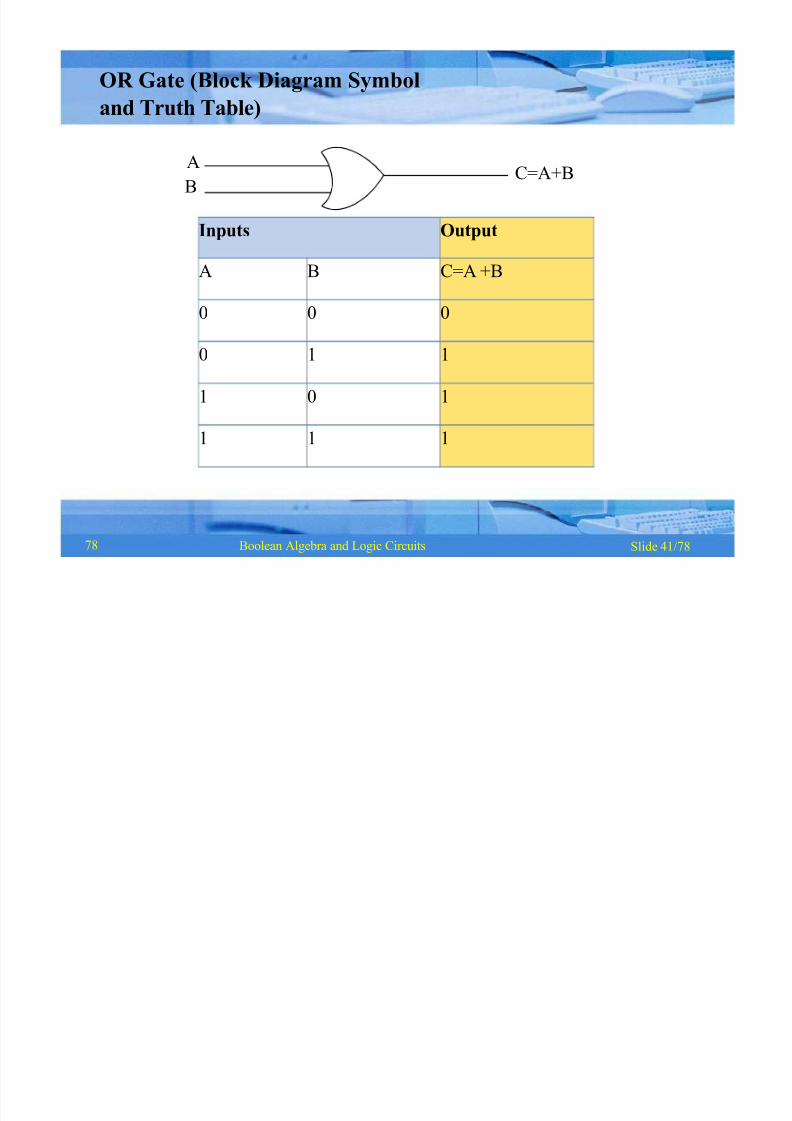
OR Gate
§ Physical realization of logical addition (OR) operation
§ Generates an output signal of 1 if at least one of the
input signals is also 1
77
8/8/2019 1 4-Boolean Algebra
http://slidepdf.com/reader/full/1-4-boolean-algebra 42/79
Inputs Output
A B C=A +B
0 0 0
0 1 1
1 0 1
1 1 1
Slide 41/78Boolean Algebra and Logic Circuits
C=A+BA
B
OR Gate (Block Diagram Symbol
and Truth Table)
78

8/8/2019 1 4-Boolean Algebra
http://slidepdf.com/reader/full/1-4-boolean-algebra 43/79
Slide 42/78Boolean Algebra and Logic Circuits
NOT Gate
§ Physical realization of complementation operation
§ Generates an output signal, which is the reverse of
the input signal
78

8/8/2019 1 4-Boolean Algebra
http://slidepdf.com/reader/full/1-4-boolean-algebra 44/79
Input Output
A A
0 1
1 0
Slide 43/78Boolean Algebra and Logic Circuits
A A
NOT Gate (Block Diagram Symbol
and Truth Table)
79

8/8/2019 1 4-Boolean Algebra
http://slidepdf.com/reader/full/1-4-boolean-algebra 45/79
Slide 44/78Boolean Algebra and Logic Circuits
§
§
1 if any one of the inputs is a 0
0 when all the inputs are 1
NAND Gate
§ Complemented AND gate
§ Generates an output signal of:
79

8/8/2019 1 4-Boolean Algebra
http://slidepdf.com/reader/full/1-4-boolean-algebra 46/79
Inputs Output
A B C = A +B0 0 1
0 1 1
1 0 1
1 1 0
Slide 45/78Boolean Algebra and Logic Circuits
A
B C= A B= A B=A +B
NAND Gate (Block Diagram Symbol
and Truth Table)
79

8/8/2019 1 4-Boolean Algebra
http://slidepdf.com/reader/full/1-4-boolean-algebra 47/79
Slide 46/78Boolean Algebra and Logic Circuits
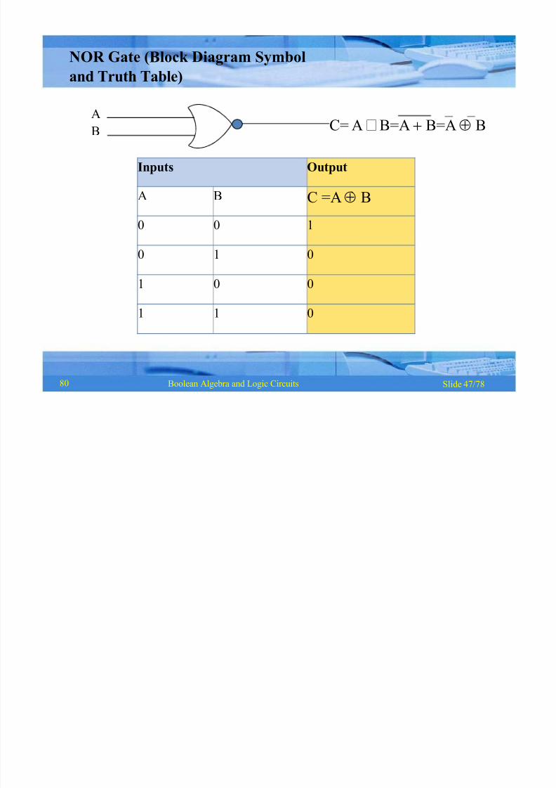
§
§
1 only when all inputs are 0
0 if any one of inputs is a 1
NOR Gate
§ Complemented OR gate
§ Generates an output signal of:
79
8/8/2019 1 4-Boolean Algebra
http://slidepdf.com/reader/full/1-4-boolean-algebra 48/79
Inputs Output
A B C =AB
0 0 1
0 1 0
1 0 0
1 1 0
Slide 47/78Boolean Algebra and Logic Circuits
A
B C= A B=A B=A B
NOR Gate (Block Diagram Symbol
and Truth Table)
80

8/8/2019 1 4-Boolean Algebra
http://slidepdf.com/reader/full/1-4-boolean-algebra 49/79
Slide 48/78Boolean Algebra and Logic Circuits
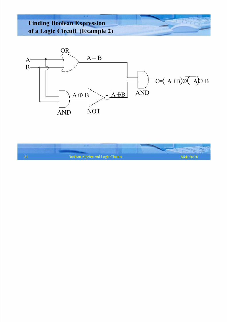
Logic Circuits
§ When logic gates are interconnected to form a gating /
logic network, it is known as a combinational logic circuit
§ The Boolean algebra expression for a given logic circuit
can be derived by systematically progressing from input
to output on the gates
§ The three logic gates (AND, OR, and NOT) are logically
complete because any Boolean expression can be
realized as a logic circuit using only these three gates
80

8/8/2019 1 4-Boolean Algebra
http://slidepdf.com/reader/full/1-4-boolean-algebra 50/79
Slide 49/78Boolean Algebra and Logic Circuits
B
C
AA
NOT
OR
B+C
D= A B + CAND
Finding Boolean Expression
of a Logic Circuit (Example 1)
80
8/8/2019 1 4-Boolean Algebra
http://slidepdf.com/reader/full/1-4-boolean-algebra 51/79
Slide 50/78Boolean Algebra and Logic Circuits
A
B
NOT
OR
C=A +BA B
AB
AND
A B
AB AND
Finding Boolean Expression
of a Logic Circuit (Example 2)
81
8/8/2019 1 4-Boolean Algebra
http://slidepdf.com/reader/full/1-4-boolean-algebra 52/79
Slide 51/78Boolean Algebra and Logic Circuits
AB
AB + C
A
B
C
OR
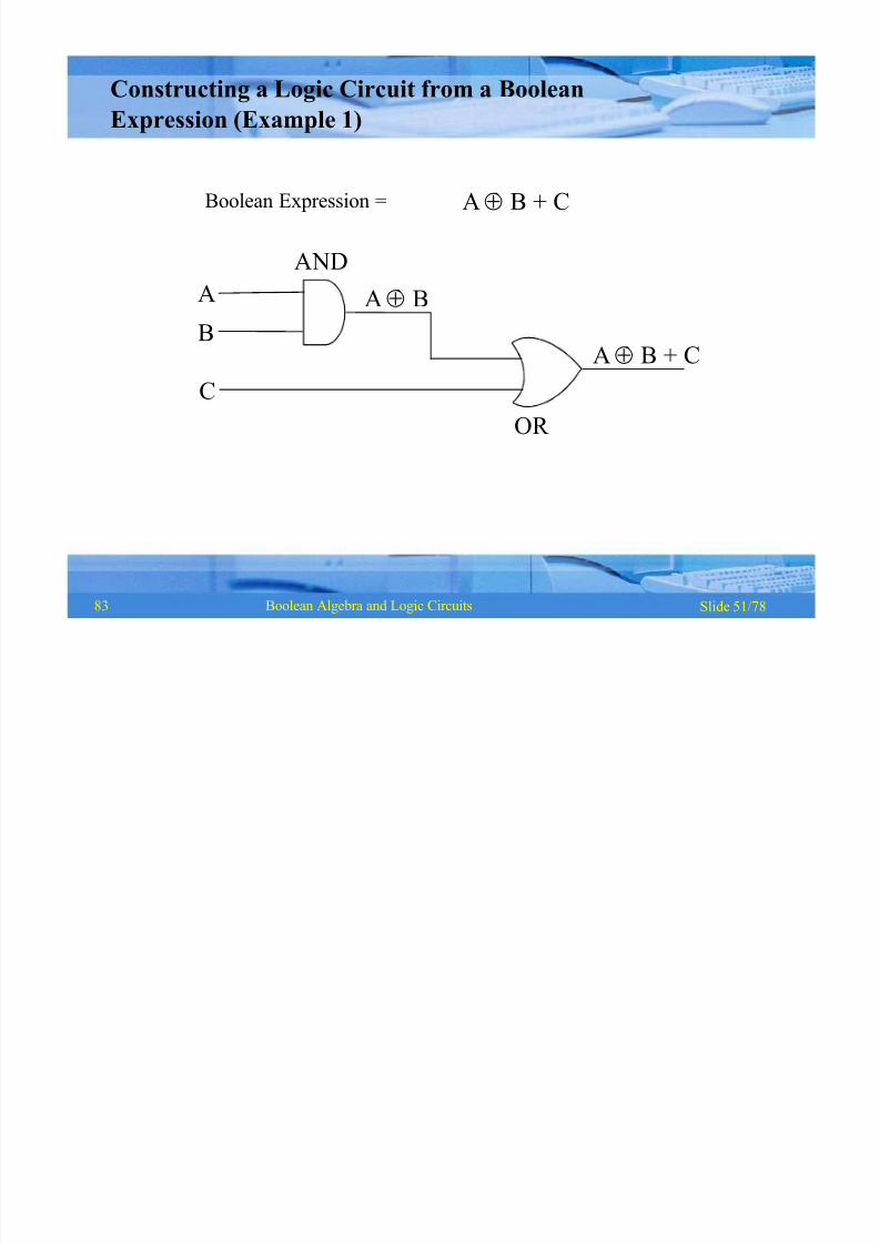
Boolean Expression =
AND
AB + C
Constructing a Logic Circuit from a Boolean
Expression (Example 1)
83

8/8/2019 1 4-Boolean Algebra
http://slidepdf.com/reader/full/1-4-boolean-algebra 53/79
Slide 52/78Boolean Algebra and Logic Circuits
A B
AND
A
B
Boolean Expression = A B + C D + E F
C DC
D
E F
AND
AND
EF
A B + C D + E F
AND
A B NOT
E F
NOT
Constructing a Logic Circuit from a Boolean
Expression (Example 2)
83
8/8/2019 1 4-Boolean Algebra
http://slidepdf.com/reader/full/1-4-boolean-algebra 54/79
Slide 53/78Boolean Algebra and Logic Circuits
§
§
Basic logic gates (AND, OR, and NOT) are
logically complete
Sufficient to show that AND, OR, and NOT
gates can be implemented with NAND
gates
Universal NAND Gate
§ NAND gate is an universal gate, it is alone
sufficient to implement any Boolean
expression
§ To understand this, consider:
84
8/8/2019 1 4-Boolean Algebra
http://slidepdf.com/reader/full/1-4-boolean-algebra 55/79
Slide 54/78Boolean Algebra and Logic Circuits
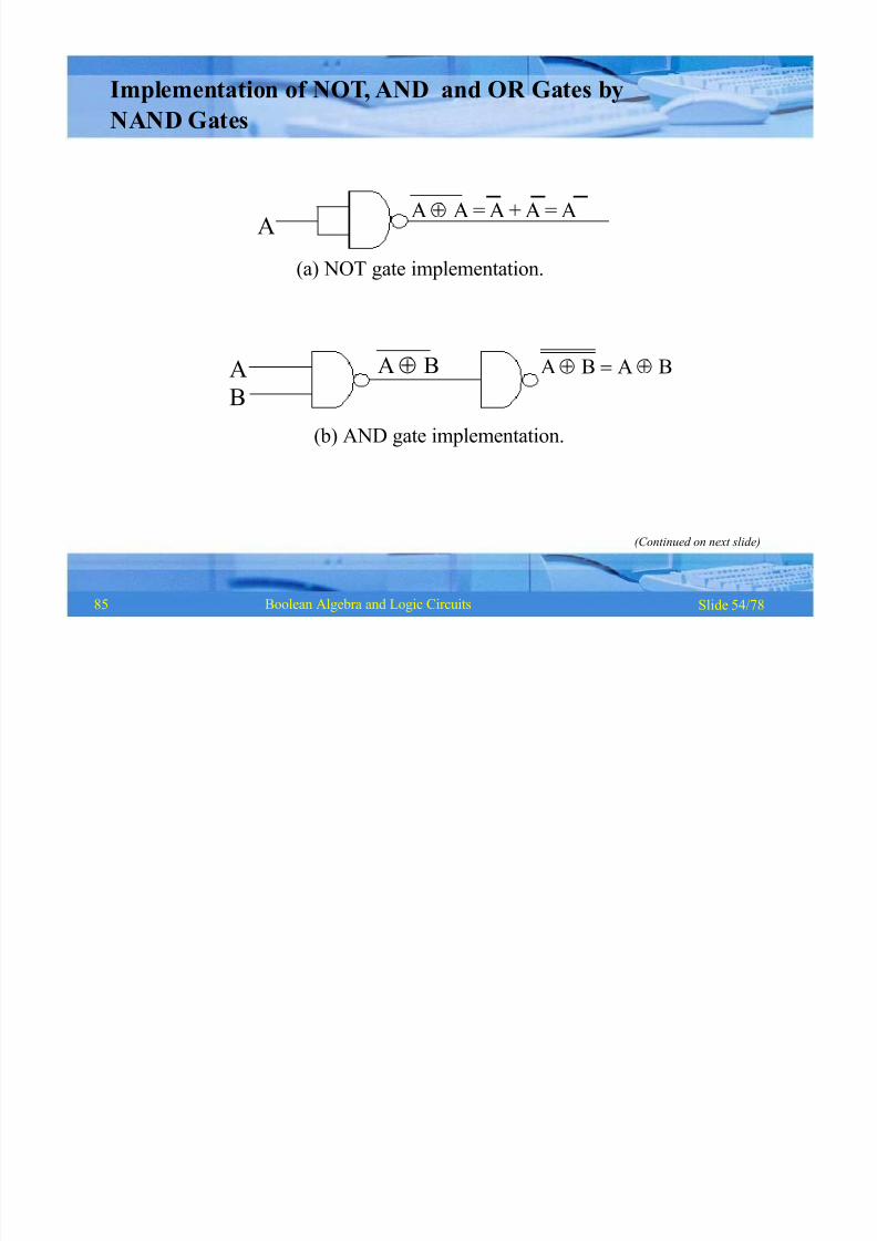
AA A = A + A = A
(a) NOT gate implementation.
A AB !A BA B
Implementation of NOT, AND and OR Gates by
NAND Gates
B
(b) AND gate implementation.
(Continued on next slide)
85
8/8/2019 1 4-Boolean Algebra
http://slidepdf.com/reader/full/1-4-boolean-algebra 56/79
Slide 55/78Boolean Algebra and Logic Circuits
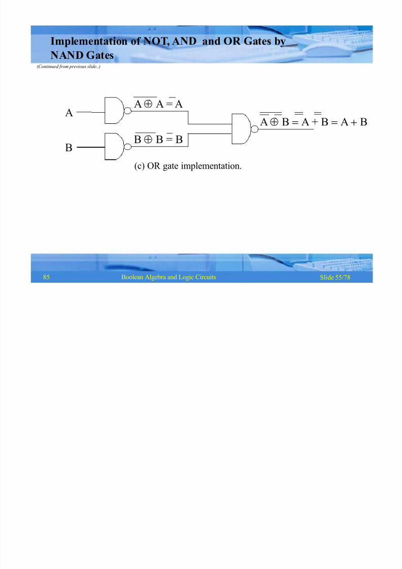
AB !A + B !A BA
B
AA = A
B B = B
(c) OR gate implementation.
Implementation of NOT, AND and OR Gates by
NAND Gates(Continued from previous slide..)
85
8/8/2019 1 4-Boolean Algebra
http://slidepdf.com/reader/full/1-4-boolean-algebra 57/79
Slide 56/78Boolean Algebra and Logic Circuits
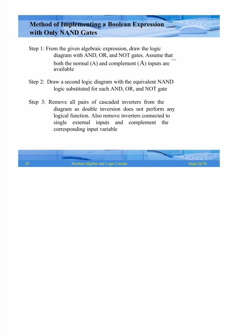
Method of Implementing a Boolean Expression
with Only NAND Gates
Step 1: From the given algebraic expression, draw the logic
diagram with AND, OR, and NOT gates. Assume that
both the normal (A) and complement (A) inputs areavailable
Step 2: Draw a second logic diagram with the equivalent NAND
logic substituted for each AND, OR, and NOT gate
Step 3: Remove all pairs of cascaded inverters from the
diagram as double inversion does not perform any
logical function. Also remove inverters connected to
single external inputs and complement the
corresponding input variable
85
8/8/2019 1 4-Boolean Algebra
http://slidepdf.com/reader/full/1-4-boolean-algebra 58/79
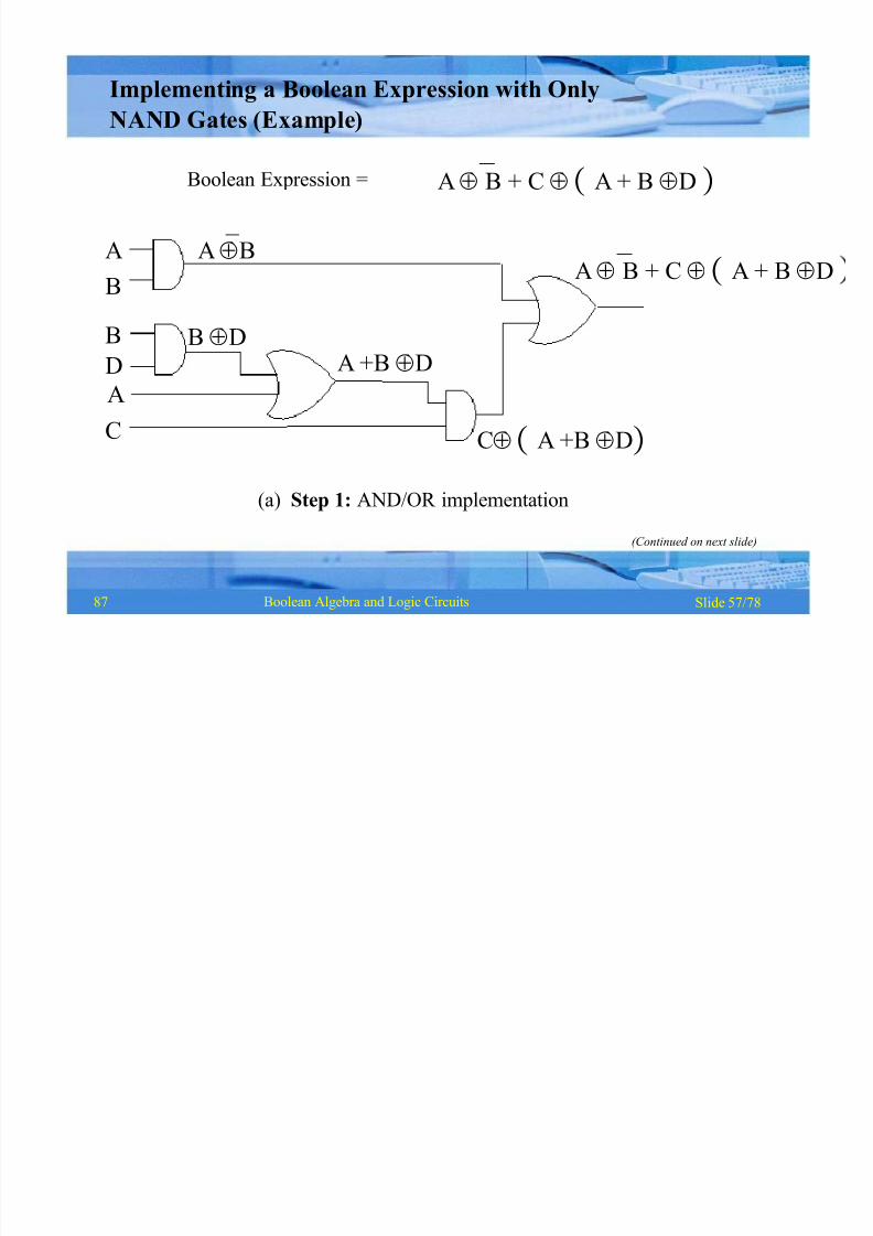
Slide 57/78Boolean Algebra and Logic Circuits
Boolean Expression =
A
B
B
D
A
C
AB
B D
AB + C A + B D
Implementing a Boolean Expression with Only
NAND Gates (Example)
AB + C A + B D
A +B D
CA +B D
(a) Step 1: AND/OR implementation
(Continued on next slide)
87
8/8/2019 1 4-Boolean Algebra
http://slidepdf.com/reader/full/1-4-boolean-algebra 59/79
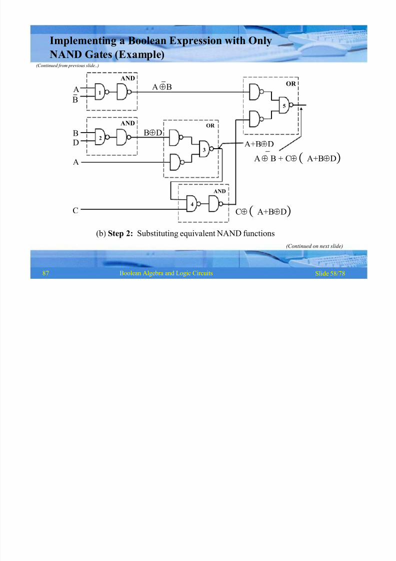
Slide 58/78Boolean Algebra and Logic Circuits
AND
OR
5
OR
3
4
A
AND
2
AND
B
D
A
C
1
B
AB
A+BD
AB + CA+BD
CA+BD
BD
Implementing a Boolean Expression with Only
NAND Gates (Example)(Continued from previous slide..)
(b) Step 2: Substituting equivalent NAND functions
(Continued on next slide)
87
8/8/2019 1 4-Boolean Algebra
http://slidepdf.com/reader/full/1-4-boolean-algebra 60/79
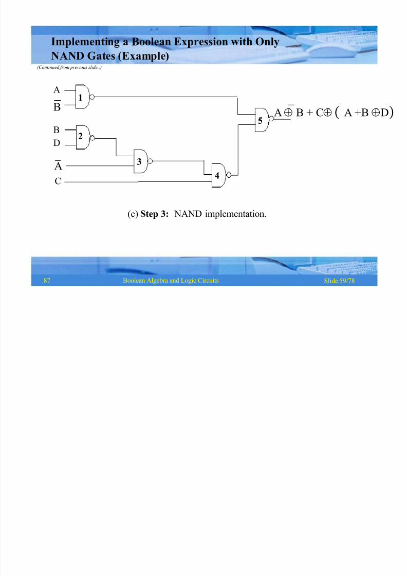
Slide 59/78Boolean Algebra and Logic Circuits
(c)S
tep 3: NAND implementation.
AB + CA +B D
A
B
B
D
A
C
1
2
3
4
5
Implementing a Boolean Expression with Only
NAND Gates (Example)(Continued from previous slide..)
87
8/8/2019 1 4-Boolean Algebra
http://slidepdf.com/reader/full/1-4-boolean-algebra 61/79
Slide 60/78Boolean Algebra and Logic Circuits
§
§
Basic logic gates (AND, OR, and NOT) are logically
complete
Sufficient to show that AND, OR, and NOT gates can
be implemented with NOR gates
Universal NOR Gate
§ NOR gate is an universal gate, it is alone sufficient to
implement any Boolean expression
§ To understand this, consider:
89
8/8/2019 1 4-Boolean Algebra
http://slidepdf.com/reader/full/1-4-boolean-algebra 62/79
Slide 61/78Boolean Algebra and Logic Circuits
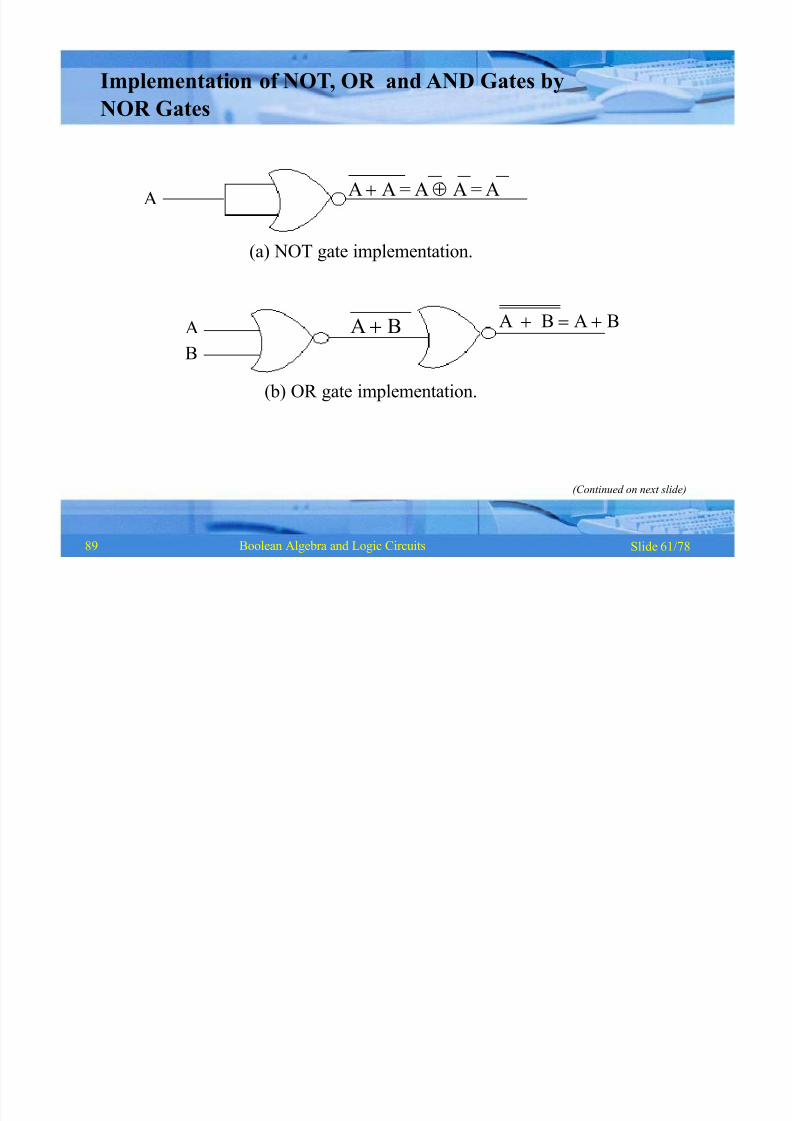
AA A = A A = A
(a) NOT gate implementation.
A A B !A BA B
Implementation of NOT, OR and AND Gates by
NOR Gates
B
(b) OR gate implementation.
(Continued on next slide)
89

8/8/2019 1 4-Boolean Algebra
http://slidepdf.com/reader/full/1-4-boolean-algebra 63/79
Slide 62/78Boolean Algebra and Logic Circuits
A + B !A B !A B
A
B
A A=A
B B =B
(c) AND gate implementation.
Implementation of NOT, OR and AND Gates by
NOR Gates(Continued from previous slide..)
89
8/8/2019 1 4-Boolean Algebra
http://slidepdf.com/reader/full/1-4-boolean-algebra 64/79
Slide 63/78Boolean Algebra and Logic Circuits
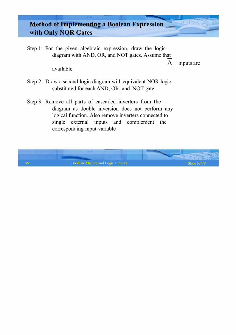
Method of Implementing a Boolean Expression
with Only NOR Gates
Step 1: For the given algebraic expression, draw the logic
diagram with AND, OR, and NOT gates. Assume that
A inputs areavailable
Step 2: Draw a second logic diagram with equivalent NOR logic
substituted for each AND, OR, and NOT gate
Step 3: Remove all parts of cascaded inverters from the
diagram as double inversion does not perform any
logical function. Also remove inverters connected to
single external inputs and complement the
corresponding input variable
89
8/8/2019 1 4-Boolean Algebra
http://slidepdf.com/reader/full/1-4-boolean-algebra 65/79
Slide 64/78Boolean Algebra and Logic Circuits
B
D
A
C
A
B
A +B DB D
CA +B D
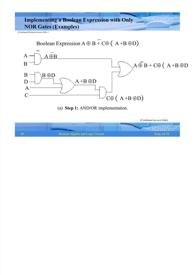
Boolean Expression A B + CA +B D=
AB
A B + CA +B D
Implementing a Boolean Expression with Only
NOR Gates (Examples)(Continued from previous slide..)
(a) Step 1: AND/OR implementation.
(Continued on next slide)
90
8/8/2019 1 4-Boolean Algebra
http://slidepdf.com/reader/full/1-4-boolean-algebra 66/79
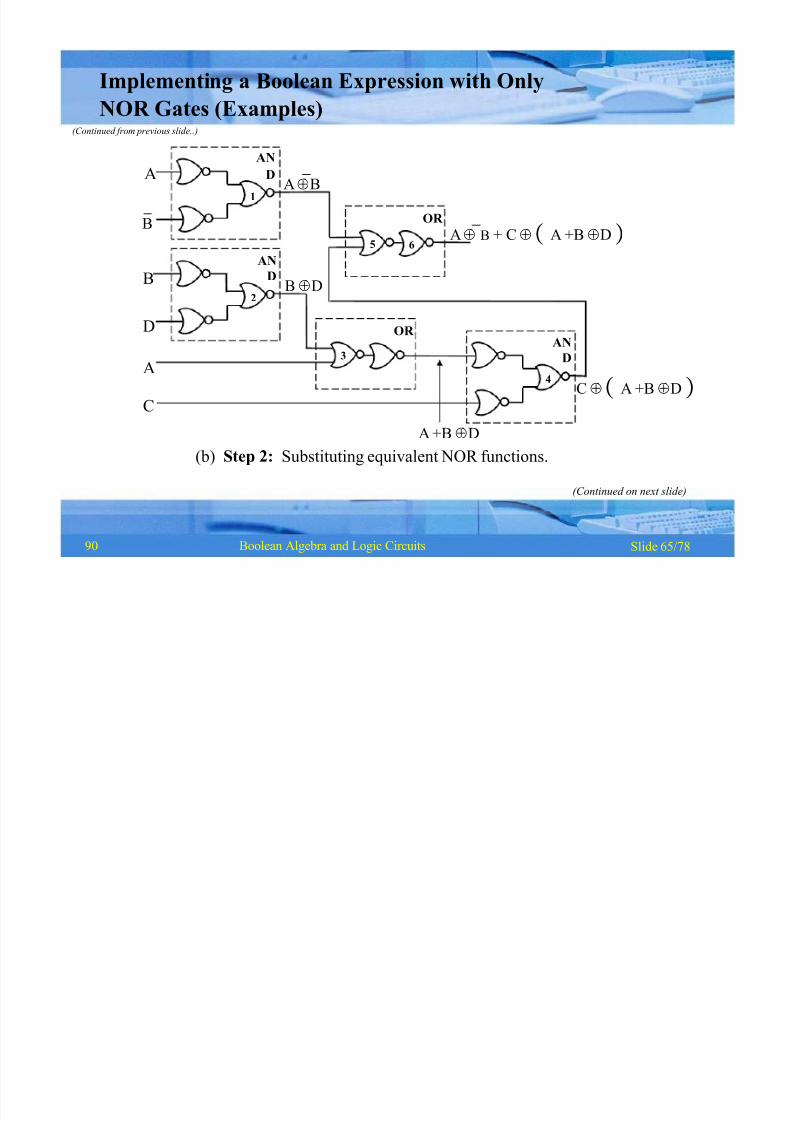
Slide 65/78Boolean Algebra and Logic Circuits
2
1
DA
B
D
B
AN
D
OR
5 6
4
AN
D
OR
3
A
C
AB
B D
C A +B D
AB + C A +B D
Implementing a Boolean Expression with Only
NOR Gates (Examples)(Continued from previous slide..)
AN
A +B D
(b) Step 2: Substituting equivalent NOR functions.
(Continued on next slide)
90

8/8/2019 1 4-Boolean Algebra
http://slidepdf.com/reader/full/1-4-boolean-algebra 67/79
Slide 66/78Boolean Algebra and Logic Circuits
AB + CA +B DAB
3
4
(c) Step 3: NOR implementation.
5
1
2
6
BD
A
C
Implementing a Boolean Expression with Only
NOR Gates (Examples)(Continued from previous slide..)
91
8/8/2019 1 4-Boolean Algebra
http://slidepdf.com/reader/full/1-4-boolean-algebra 68/79
Slide 67/78Boolean Algebra and Logic Circuits
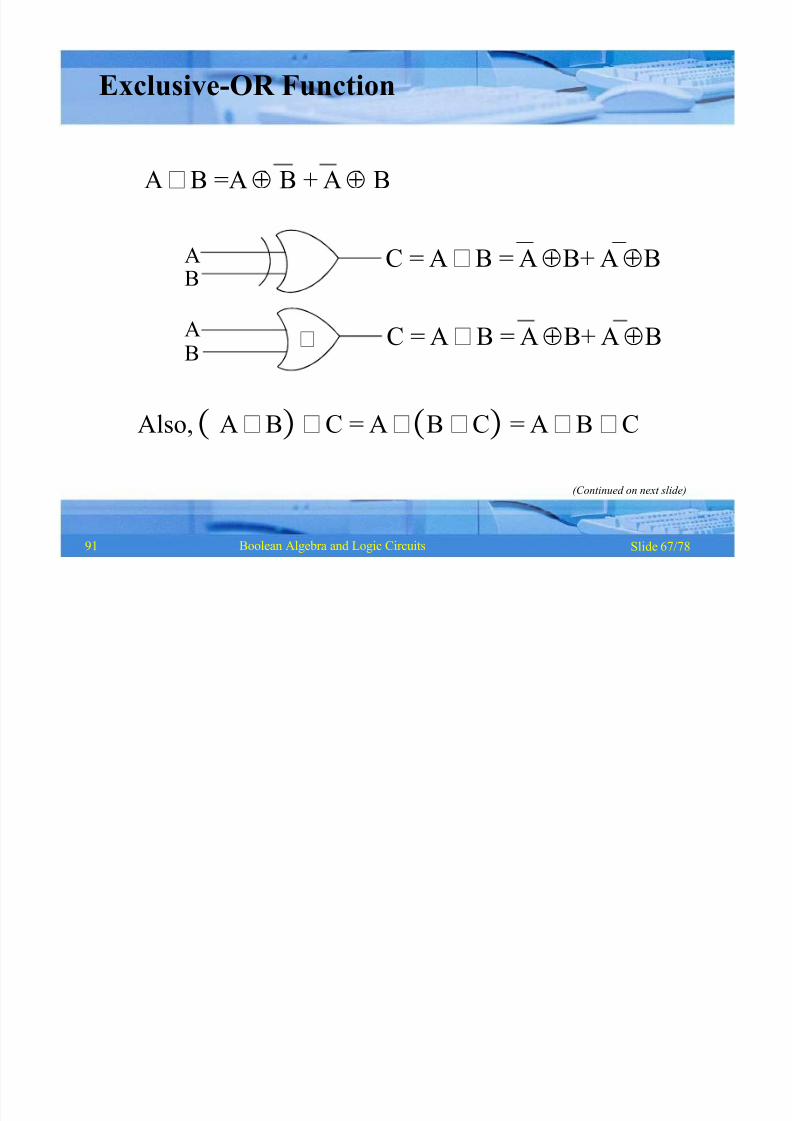
C = A B = A B+ A B
C = A B = A B+ A B
A
B
AB
Exclusive-OR Function
A B =A B + A B
Also, A B C = A B C= A B C
(Continued on next slide)
91
8/8/2019 1 4-Boolean Algebra
http://slidepdf.com/reader/full/1-4-boolean-algebra 69/79
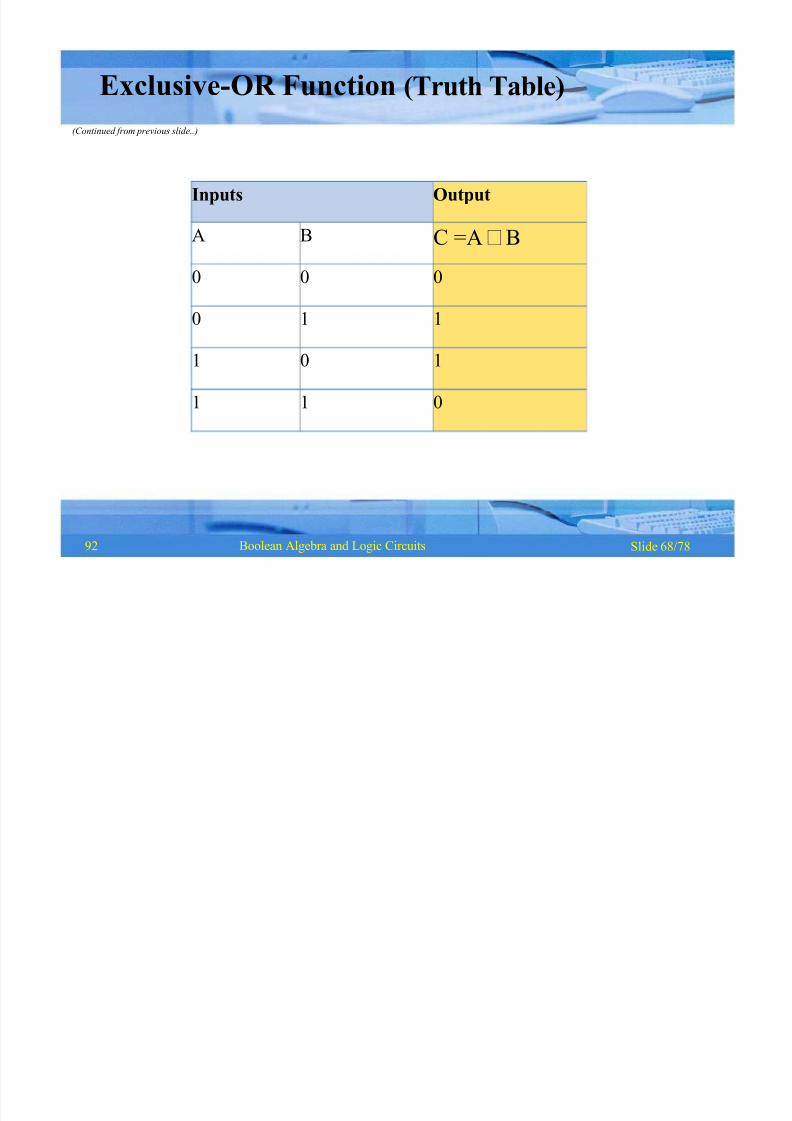
Inputs Output
A B C =A B
0 0 0
0 1 1
1 0 1
1 1 0
Slide 68/78Boolean Algebra and Logic Circuits
Exclusive-OR Function (Truth Table)
(Continued from previous slide..)
92
8/8/2019 1 4-Boolean Algebra
http://slidepdf.com/reader/full/1-4-boolean-algebra 70/79
Slide 69/78Boolean Algebra and Logic Circuits
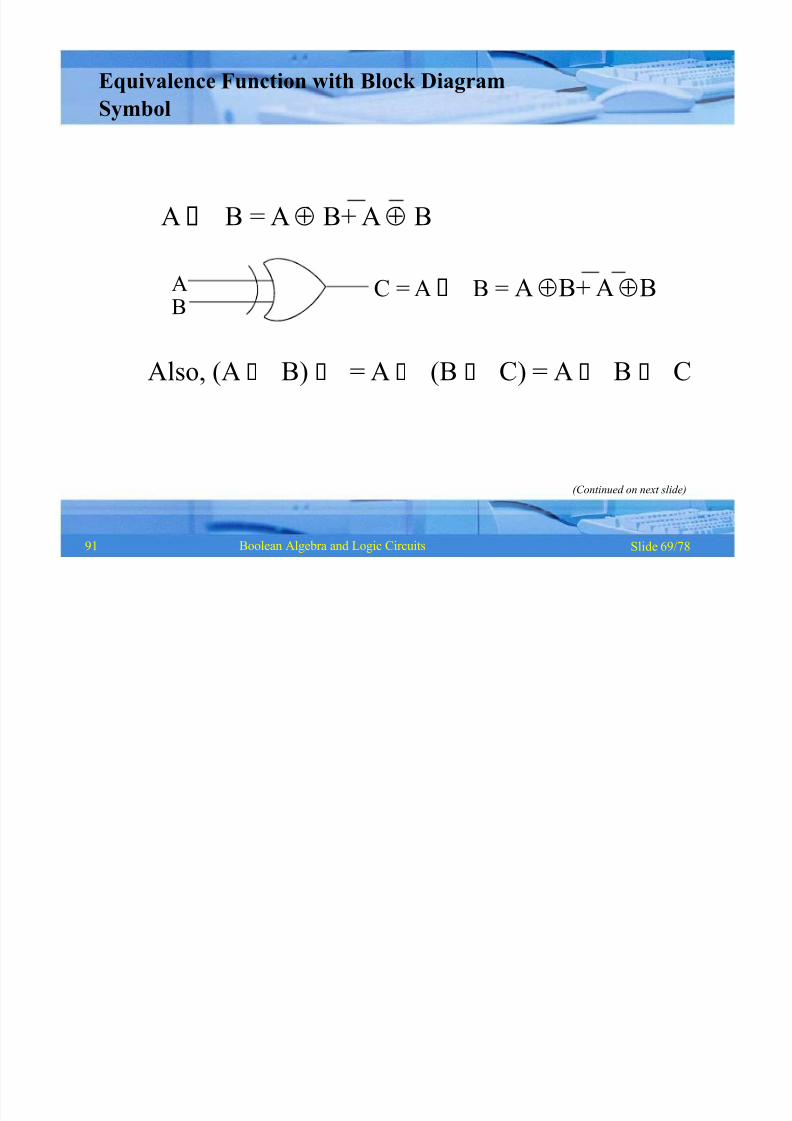
AB C = A B = A B+ A B
Also, (A B) = A (B C) = A B C
(Continued on next slide)
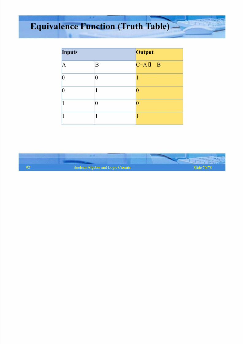
Equivalence Function with Block Diagram
Symbol
A B = A B+ A B
91
8/8/2019 1 4-Boolean Algebra
http://slidepdf.com/reader/full/1-4-boolean-algebra 71/79
Inputs Output
A B C=A B
0 0 1
0 1 0
1 0 0
1 1 1
Slide 70/78Boolean Algebra and Logic Circuits
Equivalence Function (Truth Table)
92
8/8/2019 1 4-Boolean Algebra
http://slidepdf.com/reader/full/1-4-boolean-algebra 72/79
Slide 71/78Boolean Algebra and Logic Circuits
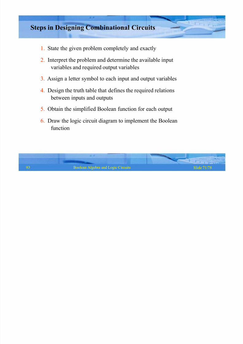
Steps in Designing Combinational Circuits
1. State the given problem completely and exactly
2. Interpret the problem and determine the available input
variables and required output variables
3. Assign a letter symbol to each input and output variables
4. Design the truth table that defines the required relations
between inputs and outputs
5. Obtain the simplified Boolean function for each output
6. Draw the logic circuit diagram to implement the Boolean
function
93

8/8/2019 1 4-Boolean Algebra
http://slidepdf.com/reader/full/1-4-boolean-algebra 73/79
Inputs Outputs
A B C S
0 0 0 0
0 1 0 1
1 0 0 1
1 1 1 0
Slide 72/78Boolean Algebra and Logic Circuits
S = A B+ A B
C = A BBoolean functions for the two outputs.
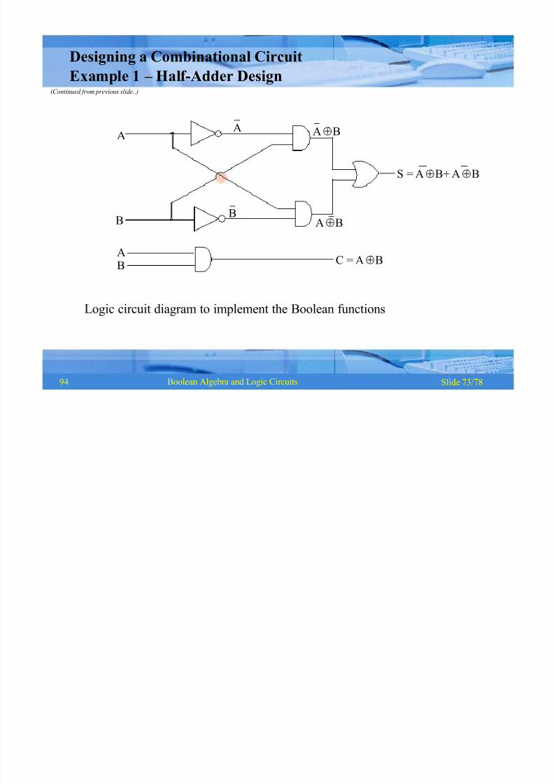
Designing a Combinational Circuit
Example 1 ± Half -Adder Design
93
8/8/2019 1 4-Boolean Algebra
http://slidepdf.com/reader/full/1-4-boolean-algebra 74/79
Slide 73/78Boolean Algebra and Logic Circuits
Logic circuit diagram to implement the Boolean functions
A
B
AB
S = A B+ A B
C = A B
A
B
AB
AB
Designing a Combinational Circuit
Example 1 ± Half -Adder Design(Continued from previous slide..)
94

8/8/2019 1 4-Boolean Algebra
http://slidepdf.com/reader/full/1-4-boolean-algebra 75/79
Inputs OutputsA B D C S
0 0
0 1
0 1
1 0
1 0 0 0 1
1 0 1 1 0
1 1 0 1 0
1 1 1 1 1
Slide 74/78Boolean Algebra and Logic Circuits
Truth table for a full adder
Designing a Combinational Circuit
Example 2 ± Full-Adder Design
(Continued on next slide)
94
8/8/2019 1 4-Boolean Algebra
http://slidepdf.com/reader/full/1-4-boolean-algebra 76/79
Slide 75/78Boolean Algebra and Logic Circuits
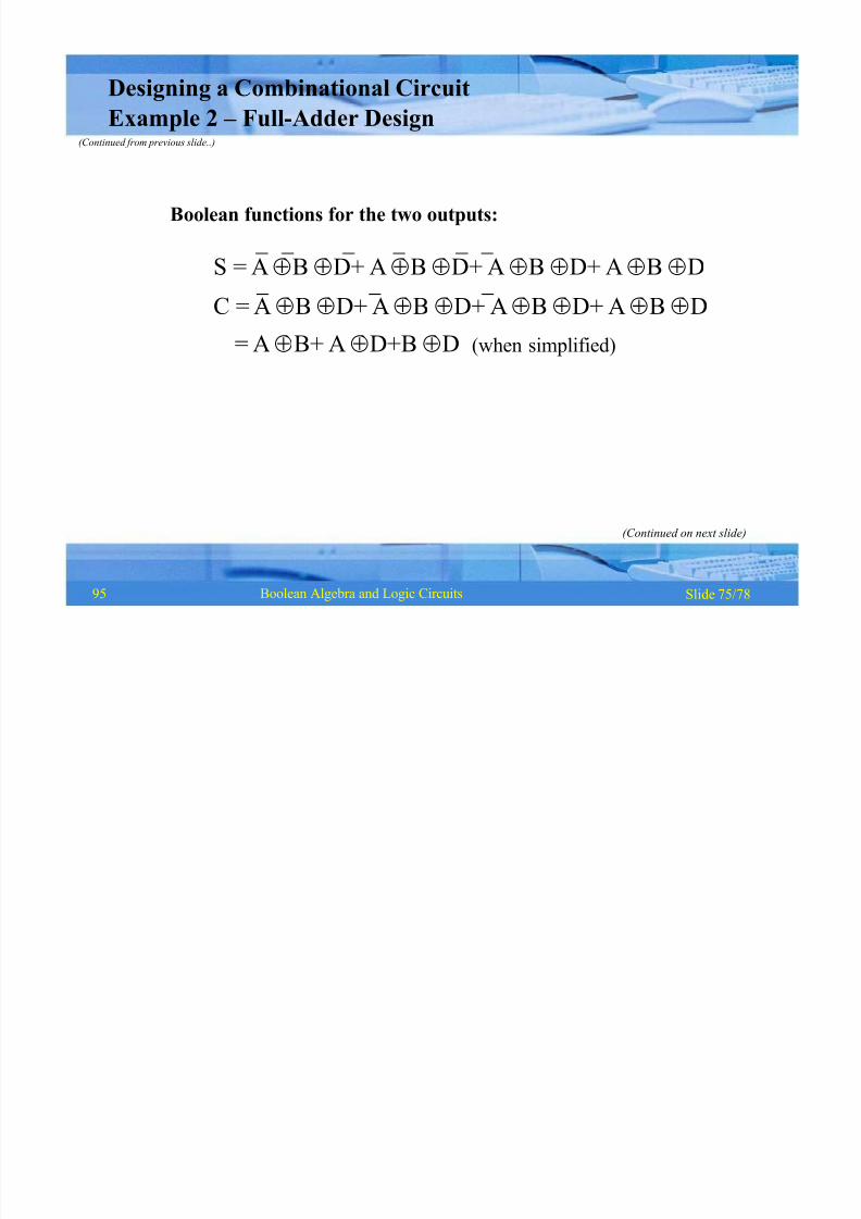
Designing a Combinational Circuit
Example 2 ± Full-Adder Design(Continued from previous slide..)
Boolean functions for the two outputs:
S = A B D+ A B D+ A B D+ A B D
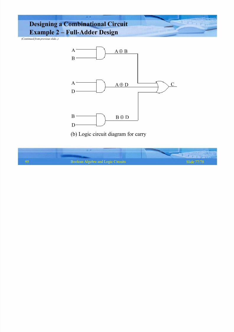
C = A B D+ A B D+ A B D+ A B D= A B+ A D+B D (when simplified)
(Continued on next slide)
95

8/8/2019 1 4-Boolean Algebra
http://slidepdf.com/reader/full/1-4-boolean-algebra 77/79
Slide 76/78Boolean Algebra and Logic Circuits
ABD
AB
ABD
AB
D
S
A B D
AB D
AB D
AB D
Designing a Combinational Circuit
Example 2 ± Full-Adder Design(Continued from previous slide..)
D
(a) Logic circuit diagram for sums
(Continued on next slide)
95
8/8/2019 1 4-Boolean Algebra
http://slidepdf.com/reader/full/1-4-boolean-algebra 78/79
Slide 77/78Boolean Algebra and Logic Circuits
C
AB
AD
B D
A
B
AD
B
D(b) Logic circuit diagram for carry
Designing a Combinational Circuit
Example 2 ± Full-Adder Design(Continued from previous slide..)
95

8/8/2019 1 4-Boolean Algebra
http://slidepdf.com/reader/full/1-4-boolean-algebra 79/79
Slide 78/78Boolean Algebra and Logic Circuits
K ey Words/Phrases
§§§
§
§§
§§
§
§§
§
§§
§
Absorption lawAND gate
Associative law
Boolean algebra
Boolean expression
Boolean functions
Boolean identities
Canonical forms for
Boolean functionsCombination logic
circuits
Cumulative law
Complement of a
function
Complementation
De Morgan¶s law
Distributive law
Dual identities
§ Equivalence function§ Exclusive-OR function
§ Exhaustive enumeration
method
§ Half-adder
§ Idempotent law
§ Involution law
§ Literal
§ Logic circuits
§ Logic gates
§ Logical addition
§ Logical multiplication
§ Maxterms
§ Minimization of Boolean
functions
§ Minterms§ NAND gate
§§§
§
§
§
§
§
§§
§
§§
NOT gateOperator precedence
OR gate
Parallel Binary Adder
Perfect induction
method
Postulates of Boolean
algebra
Principle of duality
Product-of-Sums
expression
Standard forms
Sum-of Products
expression
Truth table
Universal NAND gateUniversal NOR gate
97