Embed Size (px)
Citation preview

Preface, Contents
Product Overview 1
Installation and Setup Guidelines for the C7 2
Special Features of C7 3
Communication between theCPU and the Operator Panel 4
Communication Functions 5
C7 Digital I/O 6
C7 Analog I/O 7
C7 Universal Inputs 8
Data Set Description, I/OParameter Assignment 9
I/O Diagnostics 10
Maintenance 11
Appendices
System Messages A
Technical Specifications for the C7 BGuidelines for HandlingElectrostatically-SensitiveDevices (ESD) C
Literature on SIMATIC S7 and C7 D
Glossary, Index
C7-633 / C7-634Control Systems
Manual
This manual is part of the documentation package with the order number:
6ES7633-1AF01-8BA0
SIMATIC
10/98C79000-G7076-C634Release 01

iiC7-633/C7-634 Control Systems
C79000 G7076 C634 01
#$.()0'*)/$).)*/$ .2#$#4*0.#*0'*. -1 /* ).0- 4*0-*2)+ -.*)'.! /4.2 ''./*
+-*/ //# +-*0/)*)) / ,0$+( )/# . )*/$ .- #$"#'$"#/ $)/# ()0'42-)$)"
/-$)"' )- (-& .!*''*2.*-$)"/*/# ' 1 '*!)" -
!Warning
$)$/ ./#/ /#. 1 - + -.*)'$)%0-4*-.0./)/$'+-*+ -/4(" )- .0'/$!+-*+ -+- 0/$*).- )*//& )
Note
-2.4*0-// )/$*)/*+-/$0'-'4$(+*-/)/$)!*-(/$*)*)/# +-*0/#)'$)"/# +-*0/*-/*+-/$0'-
+-/*!/# *0( )//$*)
# 1$ .4./ ((4*)'4 . /0+)*+ -/ $)*)%0)/$*)2$/#/#$.()0'
)'4qualified personnel .#*0' ''*2 /*$)./'')2*-&*)/#$. ,0$+( )/0'$!$ + -.*).
- !$) .+ -.*).2#*- 0/#*-$5 /**(($..$*)/*"-*0))/*/"$-0$/. ,0$+( )/)
.4./ (.$)*-) 2$/# ./'$.# .! /4+-/$ .)./)-.
*/ /# !*''*2$)"
!Warning
#$. 1$ )$/.*(+*) )/.(4*)'4 0. !*-/# ++'$/$*). .-$ $)/# /'*"*-/# / #)$' .-$+/$*))*)'4$)*)) /$*)2$/# 1$ .*-*(+*) )/.!-*(*/# -()0!/0- -.2#$##1 )++-*1 *-- *(( ) 4$ ( ).
#$.+-*0/)*)'4!0)/$*)*-- /'4).! '4$!$/$./-).+*-/ ./*- . /0+)$)./'' *-- /'4)*+ -/ )($)/$) .- *(( )
!Caution
UL + CSA: Lithium Battery Replacement)" -*! 3+'*.$*)$!// -4$.$)*-- /'4- +' +' *)'42$/#.( *- ,0$1' )//4+ - *(( ) 4/# ()0!/0- -$.+*. *!0. // -$ .*-$)"/*/# ()0!/0- -.$)./-0/$*).
!Warning
FM WARNING
6
)) - - "$./ - /- (-&.*!
#$-+-/$ .0.$)"!*-/# $-*2)+0-+*. .)4*/# -)( .$)/#$.*0( )/2#$#- ! -/*/- (-&.($"#/
$)!-$)" 0+*)/# -$"#/.*!/# /- (-&*2) -.
We have checked the contents of this manual for agreement with thehardware and software described. Since deviations cannot beprecluded entirely, we cannot guarantee full agreement. However,the data in this manual are reviewed regularly and any necessarycorrections included in subsequent editions. Suggestions forimprovement are welcomed.
Siemens AG 19980% //*#)" 2$/#*0/+-$*-)*/$
Disclaimer of LiabilityCopyright Siemens AG 1998 All rights reserved
The reproduction, transmission or use of this document or itscontents is not permitted without express written authority.Offenders will be liable for damages. All rights, including rightscreated by patent grant or registration of a utility model or design, arereserved.
$ ( ).Bereich Automatisierungs- und AntriebstechnikGeschaeftsgebiet Industrie-AutomatisierungssystemePostfach 4848, D-90327 Nuernberg
Siemens Aktiengesellschaft C79000–G7076–C634
Safety Guidelines
Qualified Personnel
Correct Usage
Trademarks

iiiC7-633/C7-634 Control SystemsC79000-G7076-C634-01
Preface
This manual provides you with a complete overview of the C7-633 P,C7-633 DP, C7-634 P and C7-634 DP control systems. It offers support forthe installation and commissioning of these systems, outlines the possibilitiesfor connecting other devices, and introduces the components required forthis.
This manual is valid for the following device variants:
C7 Order Number
C7-633 P 6ES7633-1DF00-0AE3
C7-633 DP 6ES7633-2BF00-0AE3
C7-634 P 6ES7634-2DBF00-0AE3
C7-634 DP 6ES7634-2BF00-0AE3
This manual is intended for personnel with the necessary qualifications forcommissioning, operating, and programming the hardware product described.
You should be familiar with the use of computers or devices with similarfunctions to a PC (for example, programming devices) under the operatingsystem Windows 95 / NT 4.0 and have some knowledge of the STEP 7Standard software and the ProTool configuration software and the relevantdocumentation.
The control systems comprise the following individual components:
SIMATIC S7-300
SIMATIC Operator Panel
You will find information on these individual components in the version ofthe C7 documentation package valid for your control systems. Thisdocumentation package comprises four manuals and an instruction list. Youwill find the contents listed in Table 1-1:
Purpose of theManual
Where is thisManual Valid?
Audience andRequirements
C7 DocumentationPackage

ivC7-633/C7-634 Control Systems
C79000-G7076-C634-01
'" " $" " '
'" " $" "
"&" #$$
!"$ "
%
%
%
#$"%$ #$
%!$ #
"%
Table 1-1 C7 Documentation Package
Manual Contents
ManualC7-633/C7-634 Control Systems
Provides information on the topics:
Installation and installation guidelines for the C7-633 and C7-634
Connecting the C7 systems to a programming device and other devices
Connecting an IM 361 interface module
Features of the C7 and differences from SIMATIC S7-300 and SIMATIC Operator Panels
Communication between the CPU and the OP
ManualOperator Panel OP7, OP17
Provides information on:
Functionality
Device description
Operating modes and how to operate the OP
ManualS7-300 ProgrammableController, Hardware andInstallation
Detailed description of:
Configuring the mechanical and electrical structure
Installation and wiring
Preparing the S7-300 for commissioning
Features and technical specifications of the S7-300 CPUs
Reference Manual:S7-300 and M7-300Programmable Controllers,Module Specifications
Describes the hardware of the S7-300 modules:
Analog modules
Digital modules
Interface modules
Characteristics and technical specifications of the S7-300 modules
Instruction ListS7-300 ProgrammableController CPU 312 IFM, 314IFM, 313, 314, 315-2DP
List of instructions for the CPUs
Brief description of the instructions and the execution times
Preface

vC7-633/C7-634 Control SystemsC79000-G7076-C634-01
There is a range of user manuals which are intended to be used selectively tosupport you with the programming, expansion, and configuration of a C7control system. The figure below and the explanations which follow shouldmake it easier to use the documentation.
C7
ProgrammingAssigning Parameters Configuring
ProTool *)
If required
STL for S7-300/S7-400
LAD for S7-300/S7-400
System and StandardFunctions
STEP 7 User Manual
Program Design Manual
ProTool/Lite **)
or
FBD for S7-300/S7-400
FurtherDocumentation
Preface

viC7-633/C7-634 Control Systems
C79000-G7076-C634-01
Table 1-2 STEP 7 Documentation Package, Order Number, see Catalog ST 70
Manual Contents
User Manual:Standard Software for S7 andM7
Provides information on working with the STEP 7 applications:
Installing and starting up STEP 7 on a PC/programming device
Handling the applications with the following contents:
– Managing projects and files
– Configuring and assigning parameters to the S7-300
– Assigning symbolic names for user programs
– Creating and debugging the user program in STL/LAD
– Creating data blocks
Configuring communications between several CPUs:
– Downloading/uploading, storing, and deleting the user program
– Monitoring and modifying the user program (for example, variables)
– Monitoring and modifying the CPU (for example, operating state, memoryreset, compressing memory, protection levels)
Manual: Statement List (STL) forS7-300/400, Programming or
Manual: Ladder Logic (LAD)for S7-300/400, Programming
or
Manual:Function BlockDiagram (FBD) for S7-300/400,Programming
Reference manuals for programming with STL, LAD, or FBD:
Basics of working with STL/LAD/FBD (for example, structure of STL/LAD/FBD, number formats, syntax)
Description of all instructions in STEP 7(with sample programs)
Description of the various methods of addressing in STEP 7 (with examples)
Description of all integrated functions of the CPUs
Description of the CPU-internal registers
Reference Manual
System Software for S7-300/400,System and Standard Functions
Detailed description of:
All organization blocks (OB) and their priority classes
All standard functions (FC) integrated in STEP 7
All system functions (SFC) integrated in the operating system of a CPU
Programming Manual
System Software for S7-300/400,Program Design
Teaches the basic requirements for creating STEP 7 programs:
Guide to the efficient solution of the programming task using aPC/programming device and STEP 7
How the CPUs work (for example, memory concept, access to inputs/outputs,addressing, blocks, data types, data management)
Description of STEP 7 data management
Using the STEP 7 data types
Using linear and structured programming (with program samples)
Using block call instructions
Overview of using the STEP 7 applications for developing projects (withdetailed example)
Using test and diagnostics functions of the CPUs in the user program (for example, error OBs, status word)
Preface

viiC7-633/C7-634 Control SystemsC79000-G7076-C634-01
Table 1-3 Other Manuals that Provide Helpful Information on How to Operate the C7 Control System
Manual Contents
PG 7xx Describes the programming device (PG) hardware:
Setting up and starting up the programming device
Expansion possibilities
Configuration
Error diagnostics
ProTool / ProTool/Lite Manual for creating configurations with ProTool or ProTool/Lite:
Using ProTool/ProTool/Lite
Configuring
Displays and messages
Loading the configuration into the C7
Manual:Communication with SIMATIC
Describes communication in the SIMATIC S7/M7/C7:
Introduction to the theory of communications
Communication utilities
Structure and configuration of communication networks
Examples of the various communication possibilities
To make it easier to read this manual, we have used C7 throughout themanual to stand for the device types C7-633 P, C7-633 DP, C7-634 P, andC7-634 DP.
In the literature list at the end of the manual you will find a list of othersources of information on S7-300 and programmable logic controllers.
To make it easier for you to locate specific information, the manual has beenstructured as follows:
At the beginning of the manual, you will find a complete table of contentsfor the manual.
In the individual chapters, the information in the left margin gives anoverview of the contents of each section.
Following the appendices, there is a glossary containing definitions of theimportant technical terms used in the manual.
At the end of the manual, you will find a detailed index giving you fastaccess to the information you seek.
The C7 control system conforms to the standards listed in Appendix B.1.
Conventions
Other Sources ofInformation
Structure of ThisManual
Standards
Preface

viiiC7-633/C7-634 Control Systems
C79000-G7076-C634-01
If you have any questions about using the C7 control systems described inthis manual and cannot find an answer here, please contact the Siemensrepresentative in your area. You can obtain a list of addresses of Siemensrepresentatives worldwide from the SIMATIC Customer Support Hotline.
If you have any questions or comments on this manual, please fill out theremarks form at the end of the manual and return it to the address shown onthe form. We would be grateful if you could also take the time to answer thequestions giving your personal opinion of the manual.
Further Support
Preface

ixC7-633/C7-634 Control SystemsC79000-G7076-C634-01
Open round the clock, world-wide:
Johnson City
Nuremberg
Singapore
SIMATIC Basic Hotline
Nuremberg
SIMATIC BASIC Hotline
Johnson City
SIMATIC BASIC Hotline
Singapore
SIMATIC BASIC HotlineLocal time: Mo.-Fr. 7:00 to 19:00
Phone: +49 (911) 895-7000
Fax: +49 (911) 895-7002
E-Mail: [email protected]
GMT: +1:00
Local time: Mo.-Fr. 8:00 to 17:00
Phone: +1 423 461-2522
Fax: +1 423 461-2231
E-Mail: [email protected]
GMT: -5:00
Local time: Mo.-Fr. 8:30 to 17:30
Phone: +65 740-7000
Fax: +65 740-7001
E-Mail: [email protected]
GMT: +8:00
SIMATIC Premium Hotline(Calls charged, only with SIMATIC Card)
Time: Mo.-Fr. 0:00 to 24:00
Phone: +49 (911) 895-7777
Fax: +49 (911) 895-7001GMT: +01:00
The SIMATIC Customer Support team provides you with comprehensiveadditional information on SIMATIC products via its online services:
You can obtain general current information:
– On the Internet underhttp://www.ad.siemens.de/simatic/html_00/simatic.htm
– Using fax polling no. 08765-93 02 77 95 00
Current Product Information leaflets and downloads which you may finduseful for your product are available:
– On the Internet underhttp://www.ad.siemens.de/support/html-00/
– Via the Bulletin Board System (BBS) in Nuremberg (SIMATICCustomer Support Mailbox) under the number +49 (911) 895-7100.
To access the mailbox, use a modem with V.34 (28.8 Kbps) capabilitywhose parameters you should set as follows: 8, N, 1, ANSI, or dial inusing ISDN (x.75, 64 Kbps).
SIMATIC CustomerSupport Hotline
SIMATIC CustomerSupport OnlineServices
Preface

xC7-633/C7-634 Control Systems
C79000-G7076-C634-01
Preface

xiC7-633/C7-634 Control SystemsC79000-G7076-C634-01
Contents
Preface iii. . . . . . . . . . . . . . . . . . . . . . . . . . . . . . . . . . . . . . . . . . . . . . . . . . . . . . . . . . . . . . . .
1 Product Overview 1-1. . . . . . . . . . . . . . . . . . . . . . . . . . . . . . . . . . . . . . . . . . . . . . . . . . . . . .
1.1 Product Variants 1-2. . . . . . . . . . . . . . . . . . . . . . . . . . . . . . . . . . . . . . . . . . . . . . . .
1.2 Scope of Supply and Accessories for C7 1-5. . . . . . . . . . . . . . . . . . . . . . . . . . .
1.3 Components for Connection to a C7 1-6. . . . . . . . . . . . . . . . . . . . . . . . . . . . . . .
2 Installation and Setup Guidelines for the C7 2-1. . . . . . . . . . . . . . . . . . . . . . . . . . . . . .
2.1 Labeling Strips 2-2. . . . . . . . . . . . . . . . . . . . . . . . . . . . . . . . . . . . . . . . . . . . . . . . . .
2.2 Mechanical Installation 2-5. . . . . . . . . . . . . . . . . . . . . . . . . . . . . . . . . . . . . . . . . . .
2.3 Electrical Installation 2-9. . . . . . . . . . . . . . . . . . . . . . . . . . . . . . . . . . . . . . . . . . . . .
2.4 Connector Assignments 2-13. . . . . . . . . . . . . . . . . . . . . . . . . . . . . . . . . . . . . . . . . .
2.5 Connecting a Programming Device/PC to a C7 2-17. . . . . . . . . . . . . . . . . . . . . .
2.6 Connecting a Programming Device/PC to Several Nodes 2-18. . . . . . . . . . . . .
2.7 Setup Guidelines for Interference-Free Installation 2-20. . . . . . . . . . . . . . . . . . .
2.8 Connecting Shielded Cables 2-22. . . . . . . . . . . . . . . . . . . . . . . . . . . . . . . . . . . . . .
2.9 Encoding Connectors 2-23. . . . . . . . . . . . . . . . . . . . . . . . . . . . . . . . . . . . . . . . . . . .
2.10 Expanding the C7 with S7-300 Modules 2-24. . . . . . . . . . . . . . . . . . . . . . . . . . . .
2.11 Configuring an MPI and PROFIBUS DP Network 2-26. . . . . . . . . . . . . . . . . . . .
3 Special Features of C7 3-1. . . . . . . . . . . . . . . . . . . . . . . . . . . . . . . . . . . . . . . . . . . . . . . . . .
3.1 Variations from the Individual Components CPU and OP 3-2. . . . . . . . . . . . . .
3.2 Selecting a C7 CPU Operating Mode 3-4. . . . . . . . . . . . . . . . . . . . . . . . . . . . . .
3.3 DI/DO Status Displays 3-6. . . . . . . . . . . . . . . . . . . . . . . . . . . . . . . . . . . . . . . . . . .
3.4 Status and Error Indicators on the C7 CPU 3-7. . . . . . . . . . . . . . . . . . . . . . . . .
4 Communication between the CPU and the Operator Panel 4-1. . . . . . . . . . . . . . . . .
4.1 Configured Communications Parameters 4-2. . . . . . . . . . . . . . . . . . . . . . . . . . .
4.2 Overview of User Data Areas 4-3. . . . . . . . . . . . . . . . . . . . . . . . . . . . . . . . . . . . .
4.3 Event and Alarm Messages 4-4. . . . . . . . . . . . . . . . . . . . . . . . . . . . . . . . . . . . . . .
4.4 Keyboard and LED Image 4-8. . . . . . . . . . . . . . . . . . . . . . . . . . . . . . . . . . . . . . . . 4.4.1 System Keyboard Image 4-9. . . . . . . . . . . . . . . . . . . . . . . . . . . . . . . . . . . . . . . . . 4.4.2 Function Keyboard Image 4-10. . . . . . . . . . . . . . . . . . . . . . . . . . . . . . . . . . . . . . . . 4.4.3 LED Image 4-11. . . . . . . . . . . . . . . . . . . . . . . . . . . . . . . . . . . . . . . . . . . . . . . . . . . . .

xiiC7-633/C7-634 Control Systems
C79000-G7076-C634-01
4.5 Screen Number Area 4-12. . . . . . . . . . . . . . . . . . . . . . . . . . . . . . . . . . . . . . . . . . . .
4.6 User Version 4-13. . . . . . . . . . . . . . . . . . . . . . . . . . . . . . . . . . . . . . . . . . . . . . . . . . . .
4.7 Interface Area 4-14. . . . . . . . . . . . . . . . . . . . . . . . . . . . . . . . . . . . . . . . . . . . . . . . . . 4.7.1 Control and Checkback Bits 4-15. . . . . . . . . . . . . . . . . . . . . . . . . . . . . . . . . . . . . . 4.7.2 Data Areas in the Interface Area 4-17. . . . . . . . . . . . . . . . . . . . . . . . . . . . . . . . . .
4.8 Recipes 4-19. . . . . . . . . . . . . . . . . . . . . . . . . . . . . . . . . . . . . . . . . . . . . . . . . . . . . . . . 4.8.1 Transferring Data Records 4-20. . . . . . . . . . . . . . . . . . . . . . . . . . . . . . . . . . . . . . . . 4.8.2 Addressing Recipes and Data Records, and the Requisite
Data Areas 4-20. . . . . . . . . . . . . . . . . . . . . . . . . . . . . . . . . . . . . . . . . . . . . . . . . . . . . 4.8.3 Synchronization during Transfer - Normal Case 4-21. . . . . . . . . . . . . . . . . . . . . . 4.8.4 Synchronization during Transfer - Special Cases 4-22. . . . . . . . . . . . . . . . . . . .
4.9 Notes on Optimization 4-23. . . . . . . . . . . . . . . . . . . . . . . . . . . . . . . . . . . . . . . . . . .
4.10 Control Jobs and Their Parameters 4-24. . . . . . . . . . . . . . . . . . . . . . . . . . . . . . . . 4.10.1 Example of How to Activate a Control Job 4-31. . . . . . . . . . . . . . . . . . . . . . . . . .
5 Communication Functions 5-1. . . . . . . . . . . . . . . . . . . . . . . . . . . . . . . . . . . . . . . . . . . . . .
5.1 Introduction 5-2. . . . . . . . . . . . . . . . . . . . . . . . . . . . . . . . . . . . . . . . . . . . . . . . . . . . .
5.2 Communication between C7/S7 Stations (MPI Subnet) 5-3. . . . . . . . . . . . . . .
5.3 Communication within a C7 Station (PROFIBUS DP or IM) 5-5. . . . . . . . . . .
6 C7 Digital I/O 6-1. . . . . . . . . . . . . . . . . . . . . . . . . . . . . . . . . . . . . . . . . . . . . . . . . . . . . . . . . . .
6.1 Digital Inputs 6-2. . . . . . . . . . . . . . . . . . . . . . . . . . . . . . . . . . . . . . . . . . . . . . . . . . .
6.2 Digital Outputs 6-5. . . . . . . . . . . . . . . . . . . . . . . . . . . . . . . . . . . . . . . . . . . . . . . . . .
6.3 DI/DO Status Displays 6-8. . . . . . . . . . . . . . . . . . . . . . . . . . . . . . . . . . . . . . . . . . .
6.4 Addressing the C7 I/O 6-9. . . . . . . . . . . . . . . . . . . . . . . . . . . . . . . . . . . . . . . . . . .
7 C7 Analog I/O 7-1. . . . . . . . . . . . . . . . . . . . . . . . . . . . . . . . . . . . . . . . . . . . . . . . . . . . . . . . . .
7.1 Analog Technology 7-2. . . . . . . . . . . . . . . . . . . . . . . . . . . . . . . . . . . . . . . . . . . . . .
7.2 Connecting Transducers to Analog Inputs 7-3. . . . . . . . . . . . . . . . . . . . . . . . . . 7.2.1 Connecting Voltage and Current Transducers 7-6. . . . . . . . . . . . . . . . . . . . . . .
7.3 Connecting Loads/Actuators to the Analog Output 7-7. . . . . . . . . . . . . . . . . . .
7.4 Analog Input Function 7-10. . . . . . . . . . . . . . . . . . . . . . . . . . . . . . . . . . . . . . . . . . . . 7.4.1 Characteristics and Technical Specifications of the Analog Input Module 7-11
7.5 Analog Output Function 7-15. . . . . . . . . . . . . . . . . . . . . . . . . . . . . . . . . . . . . . . . . .
7.6 Use and Function of the C7 Analog I/O 7-18. . . . . . . . . . . . . . . . . . . . . . . . . . . . . 7.6.1 Addressing the Analog I/O 7-18. . . . . . . . . . . . . . . . . . . . . . . . . . . . . . . . . . . . . . . . 7.6.2 Timing of the Analog I/Os 7-19. . . . . . . . . . . . . . . . . . . . . . . . . . . . . . . . . . . . . . . . . 7.6.3 Assigning Parameters to the Analog I/O 7-21. . . . . . . . . . . . . . . . . . . . . . . . . . . . 7.6.4 Representation of Analog Values 7-27. . . . . . . . . . . . . . . . . . . . . . . . . . . . . . . . . . 7.6.5 Representation of Analog Values for the Measurement Ranges
of the Analog Inputs 7-28. . . . . . . . . . . . . . . . . . . . . . . . . . . . . . . . . . . . . . . . . . . . . 7.6.6 Representation of Analog Values for the Output Range
of the Analog Outputs 7-30. . . . . . . . . . . . . . . . . . . . . . . . . . . . . . . . . . . . . . . . . . . . 7.6.7 Conversion and Cycle Time of the Analog Inputs 7-31. . . . . . . . . . . . . . . . . . . . 7.6.8 Conversion, Cycle, Settling and Response Times of Analog Outputs 7-32. . .
Contents

xiiiC7-633/C7-634 Control SystemsC79000-G7076-C634-01
7.6.9 Behavior of the Analog I/O 7-33. . . . . . . . . . . . . . . . . . . . . . . . . . . . . . . . . . . . . . . . 7.6.10 Time Interrupt/Interrupt Cycle 7-35. . . . . . . . . . . . . . . . . . . . . . . . . . . . . . . . . . . . .
7.7 Examples for Programming the Analog I/O 7-36. . . . . . . . . . . . . . . . . . . . . . . . . . 7.7.1 Block for Scaling Analog Input Values 7-36. . . . . . . . . . . . . . . . . . . . . . . . . . . . . . 7.7.2 Block for Scaling Analog Output Values 7-39. . . . . . . . . . . . . . . . . . . . . . . . . . . .
8 C7 Universal Inputs 8-1. . . . . . . . . . . . . . . . . . . . . . . . . . . . . . . . . . . . . . . . . . . . . . . . . . . . .
8.1 Universal Inputs 8-2. . . . . . . . . . . . . . . . . . . . . . . . . . . . . . . . . . . . . . . . . . . . . . . . .
8.2 Use and Function of the Universal Inputs 8-6. . . . . . . . . . . . . . . . . . . . . . . . . . . 8.2.1 Addressing Universal Inputs 8-6. . . . . . . . . . . . . . . . . . . . . . . . . . . . . . . . . . . . . . 8.2.2 Assigning Parameters to the Universal Inputs 8-9. . . . . . . . . . . . . . . . . . . . . . . 8.2.3 Interrupt Inputs and Counter Interrupts 8-12. . . . . . . . . . . . . . . . . . . . . . . . . . . . . 8.2.4 Counters 8-14. . . . . . . . . . . . . . . . . . . . . . . . . . . . . . . . . . . . . . . . . . . . . . . . . . . . . . . 8.2.5 Frequency Counters 8-17. . . . . . . . . . . . . . . . . . . . . . . . . . . . . . . . . . . . . . . . . . . . . 8.2.6 Period Time Measurement 8-19. . . . . . . . . . . . . . . . . . . . . . . . . . . . . . . . . . . . . . . . 8.2.7 External Gate Counter 8-22. . . . . . . . . . . . . . . . . . . . . . . . . . . . . . . . . . . . . . . . . . .
8.3 Example for Programming the Counters 8-23. . . . . . . . . . . . . . . . . . . . . . . . . . . .
9 Data Set Description, I/O Parameter Assignment 9-1. . . . . . . . . . . . . . . . . . . . . . . . . .
9.1 Data Set Description for Parameter Block of C7 Analog I/O and Universal Inputs 9-2. . . . . . . . . . . . . . . . . . . . . . . . . . . . . . . . . . . . . . . . . . . . .
10 I/O Diagnostics 10-1. . . . . . . . . . . . . . . . . . . . . . . . . . . . . . . . . . . . . . . . . . . . . . . . . . . . . . . .
10.1 Diagnostic Messages 10-2. . . . . . . . . . . . . . . . . . . . . . . . . . . . . . . . . . . . . . . . . . . .
10.2 Diagnostic Data of the C7 Analog I/O and Universal Inputs 10-4. . . . . . . . . . . .
10.3 Dependencies and Reactions of the Diagnostic Evaluation 10-8. . . . . . . . . . . .
11 Maintenance 11-1. . . . . . . . . . . . . . . . . . . . . . . . . . . . . . . . . . . . . . . . . . . . . . . . . . . . . . . . . . .
11.1 Changing the Backup Battery 11-2. . . . . . . . . . . . . . . . . . . . . . . . . . . . . . . . . . . . .
11.2 Replacing the C7 11-4. . . . . . . . . . . . . . . . . . . . . . . . . . . . . . . . . . . . . . . . . . . . . . . .
A System Messages A-1. . . . . . . . . . . . . . . . . . . . . . . . . . . . . . . . . . . . . . . . . . . . . . . . . . . . . .
B Technical Specifications for the C7 B-1. . . . . . . . . . . . . . . . . . . . . . . . . . . . . . . . . . . . . .
B.1 Technical Specifications B-2. . . . . . . . . . . . . . . . . . . . . . . . . . . . . . . . . . . . . . . . . .
B.2 Notes on the CE Marking B-11. . . . . . . . . . . . . . . . . . . . . . . . . . . . . . . . . . . . . . . . .
B.3 Notes for Machine Manufacturers B-12. . . . . . . . . . . . . . . . . . . . . . . . . . . . . . . . . .
B.4 Transport and Storage Conditions for Backup Batteries B-13. . . . . . . . . . . . . . .
C Guidelines for Handling Electrostatically-Sensitive Devices (ESD) C-1. . . . . . . . .
C.1 What is ESD? C-2. . . . . . . . . . . . . . . . . . . . . . . . . . . . . . . . . . . . . . . . . . . . . . . . . . .
C.2 Electrostatic Charging of Objects and Persons C-3. . . . . . . . . . . . . . . . . . . . . .
C.3 General Protective Measures against Electrostatic Discharge Damage C-4.
C.4 Taking Measurements and Working on ESD Modules C-6. . . . . . . . . . . . . . . .
C.5 Packing Electrostatically-Sensitive Devices C-6. . . . . . . . . . . . . . . . . . . . . . . . .
Contents

xivC7-633/C7-634 Control Systems
C79000-G7076-C634-01
D Literature on SIMATIC C7 and S7 D-1. . . . . . . . . . . . . . . . . . . . . . . . . . . . . . . . . . . . . . . .
Glossary Glossary-1. . . . . . . . . . . . . . . . . . . . . . . . . . . . . . . . . . . . . . . . . . . . . . . . . . . . . . . . . .
Index Index-1. . . . . . . . . . . . . . . . . . . . . . . . . . . . . . . . . . . . . . . . . . . . . . . . . . . . . . . . . . . . .
Contents

1-1C7-633/C7-634 Control SystemsC79000-G7076-C634-01
Product Overview
This chapter introduces the different variants of the device. A brief overviewof the scope of functions of the device helps to give you a first impression ofthe C7 control systems.
In addition, this chapter also explains which other components you canconnect to a C7 control system.
To operate a C7 control system you will require the following accessories:
Programming device (PG) or PC with multipoint interface (MPI),
An MPI cable
A serial cable (RS 232/TTY),
A 24-V power supply
The following programs must be loaded on the programming device orPC:
– The STEP 7 or STEP 7-Mini applications
– The configuration tool ProTool or ProTool/Lite
In This Chapter...
Accessories forOperating a C7Control System
1

1-2C7-633/C7-634 Control Systems
C79000-G7076-C634-01
1.1 Product Variants
The C7 devices are available in the following variants:
C7-633 P, C7-633 DP
C7-634 P, C7-634-DP
The C7-633 and C7-633 DP control systems have a SIMATIC S7-300CPU 315 or CPU 315-2 DP as the C7 CPU and an OP 7 with extendedfunction keys as the C7 OP (see Section 3.1).
The screen display comprises four lines of 20 characters with a characterheight of 8 mm.
The C7-633 P is fitted with an integrated I/O module and has no DPinterface.
Figure 1-1 C7-633 P
The C7-633 DP does not have an integrated on-board I/O.
Figure 1-2 C7-633 DP
Overview
C7-633 P/C7-633 DP
Product Overview

1-3C7-633/C7-634 Control SystemsC79000-G7076-C634-01
The C7-634 P and C7-634 DP control systems have a SIMATIC S7-300CPU 315 or CPU 315-2 DP as the C7 CPU and an OP 17 as the C7 OP.
The screen display can be configured as follows:
Four lines of 20 characters with 11 mm character height or
Eight lines of 40 characters with 6 mm character height.
The different character heights can also be combined with the basicconfiguration of 8*40 in a display.
The C7-634 P is fitted with an integrated I/O module and has no DPinterface.
Figure 1-3 C7-634 P
The C7-634 DP has no integrated on-board I/O.
Figure 1-4 C7-634 DP
C7-634 P/C7-634 DP
Product Overview

1-4C7-633/C7-634 Control Systems
C79000-G7076-C634-01
The C7-633 DP and C7-634 DP control systems can be connected via theintegrated DP interface to a PROFIBUS DP network.
With the C7 devices you can:
Download user programs to the C7 CPU and run them.
Communicate with other nodes in an MPI or PROFIBUS DP network viaan integrated MPI or DP interface.
Process digital and analog signals using the C7’s integral I/O.
Use interrupt inputs or counters (for purposes including frequencymetering, period duration measurement).
Load and execute operator interface configurations you created with theconfiguration tools “ProTool” or “ProTool/Lite.”
Using these configurations you can monitor and influence the processwhich you control with the user program.
Connect other S7 modules via the IM 361 interface module.
Output data to a connected printer.
The C7 contains two units that work independently of each other andcommunicate via an internal multipoint interface:
C7 CPU: controls
C7 Operator Panel: operates and monitors
The C7 CPU is independent of the C7 OP. The C7 OP continues to run, forexample, when the C7 CPU goes into STOP.
Note
The C7 CPU and the C7 OP each have an MPI address. You thereforeconfigure these components exactly the same as the stand-alone componentsCPU and OP.
These components are discussed explicitly in the manual as necessary.
PROFIBUS DP BusConnection
Scope ofFunctions
C7 Components
Product Overview

1-5C7-633/C7-634 Control SystemsC79000-G7076-C634-01
1.2 Scope of Supply and Accessories for C7
The following components are included in the scope of supply of a C7device:
C7-633 P, C7-633 DP, C7-634 P, or C7-634 DP
Battery (integrated in the device)
One grounding bar (C7-633 P and C7-634 P only)
Six shielding clips (C7-633 P and C7-634 P only)
Seal and four screw-in tensioners
Power supply connector (4-pin)
Product Information (as required)
Connector set (C7-633 P and C7-634 P only)
The following components can be ordered as important C7 standardaccessories:
Component Identifying Data Order Number
PG cable (MPI)(connects C7 to PG)
See catalog ST 70
PG cable (TTY)(serial transfer (ProTool))
PC/MPI cable 5 m
Printer cable for RS 232 serial interface(max. 16 m)
The following components can be ordered as spare parts for the C7:
Component Identifying Data Order Number
Service package Seal and 4 screw-intensioners
See catalog ST 70
Backup battery
Connector set for C7 I/Oswith solid and profiledcoding keys
Parts Supplied
Accessories
Spare Parts
Product Overview

1-6C7-633/C7-634 Control Systems
C79000-G7076-C634-01
1.3 Components for Connection to a C7
In addition to the connections to the process, you can also connect differentcomponents to the C7. The most important components and their functionsare listed in Table 1-1:
Table 1-1 Connectable Components of a C7
Component Function Illustration
Interface module (IM 361) ... connects a C7 to an expansionrack for S7-300 modules via anIM 361 connecting cable
Signal modules (SM)(digital input modules,digital output modules,analog input modules,analog output modules,analog I/O modules)
... adapt different process signallevels to the C7 CPU. They can beconnected to the C7 via an IM 361
Function modules (FM) ... for time-critical andmemory-intensive process signalprocessing tasks, for example,positioning or closed-loop control
Communications processors (CP) ... relieves the CPU ofcommunication tasks, for example,CP 342-5 DP for supporting FMSservices, point-to-point connections,S5 connections, etc.
S7-300 (CPU) ... communicates via the MPI/DPinterface with the C7 and/or othernodes in an MPI network
S7-400 (CPU) ... communicates via the MPI/DPinterface with the C7 and/or othernodes in an MPI/DP network
Product Overview

1-7C7-633/C7-634 Control SystemsC79000-G7076-C634-01
Table 1-1 Connectable Components of a C7
Component IllustrationFunction
C7 I/O module (expansion I/Os)
... is used for expanding theintegrated I/Os by 16 digital inputs,16 digital outputs, 4 analog inputs, 4analog outputs, and 4 universalinputs directly on the device
C7 simulator modules ... with switches and LEDs to allowsimulation of 16 digital inputs and 16digital outputs. It can be connected tothe C7 via an IM 361
LEDs
SIMATIC TOP Connect ... permits easy, fast, and reliablewiring of the I/O and power supplyconnectors
OP (operator panel) ... executes operator interfacefunctions
PROFIBUS bus cable with busconnector
... connects nodes of an MPI networkor L2-DP network together
Programming device cable (MPI) ... connects a programmingdevice/PC to a C7
Programming device cable (serial) ... connects a programmingdevice/PC to a C7 (RS 232/TTY).Serial transfer with ProTool
Printer ... prints out operator interfacemessages for the C7
Product Overview

1-8C7-633/C7-634 Control Systems
C79000-G7076-C634-01
Table 1-1 Connectable Components of a C7
Component IllustrationFunction
Programming device (PG) or PCwith the STEP 7 and ProToolsoftware packages
... configures, assigns parameters,programs, and tests the C7
RS 485 repeater ... for amplifying the signals in anMPI network or L2-DP network, andfor linking segments of an MPI orL2-DP network
Product Overview

1-9C7-633/C7-634 Control SystemsC79000-G7076-C634-01
Figure 1-5 shows some possible connections to other devices.
IM 361
C7
S7-300 modules
S7-300 CPU
PG
Printer
OP 25
PROFIBUS DP connectionMPI
RS 232 (V.24)/TTYIM 361ET 200 M with,
e.g. FM 355
Figure 1-5 Some C7 Connection Possibilities
Example
Product Overview

1-10C7-633/C7-634 Control Systems
C79000-G7076-C634-01
Product Overview

2-1C7-633/C7-634 Control SystemsC79000-G7076-C634-01
Installation and Setup Guidelinesfor the C7
Section Description Page
2.1 Labeling Strips 2-2
2.2 Mechanical Installation 2-5
2.3 Electrical Installation 2-9
2.4 Connector Assignments 2-13
2.5 Connecting a Programming Device/PC to a C7 2-17
2.6 Connecting a Programming Device/PC to Several Nodes 2-18
2.7 Setup Guidelines for Interference-Free Installation 2-20
2.8 Connecting Shielded Cables 2-22
2.9 Encoding Connectors 2-23
2.10 Expanding the C7 with S7-300 Modules 2-24
2.11 Configuring an MPI and PROFIBUS DP Network 2-26
ChapterOverview
2

2-2C7-633/C7-634 Control Systems
C79000-G7076-C634-01
2.1 Labeling Strips
The function keys are labeled using labeling strips which are inserted into thekeypad from the side. When shipped, the function keys are labeled asfollows:
C7-633: F1 to F4, K1 to K8, and K9 to K16.
C7-634: F1 to F8, K1 to K8, and K9 to K16.
By exchanging the labeling strips, you can label the function keys of your C7specifically for your plant.
To make your own labeling strips, use transparent foil so that the LEDs in thefunction keys remain visible. Label the foil using either a printer or anindelible pen so it cannot be erased. Cut the strips out using the templatesshown in Figures 2-1 (C7-633) and 2-2 (C7-634).
Note
Laser printouts are not indelible. You should therefore protect the printedsheet with transparent adhesive foil.
Shipped with the ProTool configuration software are the Word filesSLIDE633.DOC and SLIDE634.DOC . The files contain formattedtemplates for labeling the function keys of C7-633 and C7-634 and can alsobe used to edit and print your own individual labeling strips with a minimumof effort. You will find the SLIDE63x.DOC and SLIDE634.DOC files inthe ProTool directory “Utility.”
Plant-SpecificLabeling
Making LabelingStrips
Installation and Setup Guidelines for the C7

2-3C7-633/C7-634 Control SystemsC79000-G7076-C634-01
Key surface can be labeledTransparent LED window
Figure 2-1 Dimensions of the Labeling Strips for the C7-633
Key surface can be labeledTransparent LED window
Figure 2-2 Dimensions of the Labeling Strips for the C7-634
Installation and Setup Guidelines for the C7

2-4C7-633/C7-634 Control Systems
C79000-G7076-C634-01
The C7 is designed for user-friendly insertion of the labeling strips. Thelabeling strips should only be changed when the C7 is not installed. Proceedas follows to change the strips:
1. Pull the labeling strips you want to replace out of the device.
2. From the rear of the device, push the new strips into the relevant slots onthe side.
Note
The labels on the strips must be indelible before the strips are inserted. If thekeypad membrane is dirtied or smudged from the inside, it cannot be cleanedand can only be replaced at the factory of origin.
Labeling strips
Figure 2-3 Inserting Labeling Strips
Changing LabelingStrips
Installation and Setup Guidelines for the C7

2-5C7-633/C7-634 Control SystemsC79000-G7076-C634-01
2.2 Mechanical Installation
The C7 control system has been prepared for fixed installation in a controlpanel or cabinet door. Proceed as follows to install the C7:
1. Make a cutout in the control panel dimensions 230.5 x 158.5 mm (samesize for all device variants). See Figure 2-5.
2. Push the enclosed seal over the casing from behind.
3. Insert the C7 into the prepared cutout.
4. Guide the fixing hooks of the enclosed screw-in tensioner 1 into theappropriate recesses in the casing of the C7.
5. Tighten the C7 using a screwdriver from the rear of the control panel 2.
Control panel
Figure 2-4 C7-633 DP with Screw-In Tensioners
Installing theDevice
Installation and Setup Guidelines for the C7

2-6C7-633/C7-634 Control Systems
C79000-G7076-C634-01
203.5
240
230.5+0.5
158.5+0.5
Cutout in front panel
Figure 2-5 Dimension Drawings for Cutout in Control Panel (All Device Variants)
When installing a C7, please note the following:
The plate of a control panel may be 2 to 4 mm thick. Make sure the sealring fits tightly in all places.
When you tighten the fixings, the seal ring should be visible(min. 0.5 mm).
Gaps of at least 50 and 70 mm must be left on the sides of the C7 foroutgoing cables and air circulation as shown in Figure 2-6.
The seal ring on the front panel must sit perfectly.
The tabs of the insertion strips must not be trapped.
The C7 must be protected from direct sunlight.
Note
The C7 can be mounted and operated in different positions, wherebyhorizontal mounting is preferable.
It is also possible to mount the system rotated around a horizontal axis (seeAppendix B.1 Technical Specifications “Operational ambient temperature”).
Operation is not permissible in a position that is tilted around a vertical axis.
InstallationGuidelines
Installation and Setup Guidelines for the C7

2-7C7-633/C7-634 Control SystemsC79000-G7076-C634-01
50
15
70 70
Horizontal axis
Figure 2-6 Gap Dimensions to be Observed when Installing the C7
26.9
41.5
24.7
42.1
42.6
44
69
158
74.46.2
5
40.9
33
26.9
56.1
230
Figure 2-7 Dimension Drawings for the C7-633 DP/C7-634 DP
Installation and Setup Guidelines for the C7

2-8C7-633/C7-634 Control Systems
C79000-G7076-C634-01
26.9
42.6
44.1
46
56.5
65
69
71.3533
40.9
26.971.1
6.289.4
5
158
67.486
51.6
19.5
230
Figure 2-8 Dimension Drawings for the C7-633 P/C7-634 P
Installation and Setup Guidelines for the C7

2-9C7-633/C7-634 Control SystemsC79000-G7076-C634-01
2.3 Electrical Installation
The following plug and socket connectors (interfaces) required forconnecting the various inputs and outputs of the on-board I/O of theC7-633 P or C7-634 P are provided.
AUX Digital Input (X10)
Analog Output (X13)
Digital Input (X12)
Digital Output (X11)
DI/DO-24V DC Power Supply(X10)
Analog Input (X14)
Figure 2-9 A View of the C7-633 P with On-Board I/O Interfaces
Table 2-1 Pin Assignments of the Digital Inputs
Pin No. Signal Explanation
0.0 I0.0 Digital input 0
0.1 I0.1 Digital input 1
0.2 I0.2 Digital input 2
0.3 I0.3 Digital input 3
0.4 I0.4 Digital input 4
0.5 I0.5 Digital input 5
0.6 I0.6 Digital input 6
0.7 I0.7 Digital input 7
1.0 I1.0 Digital input 8
1.1 I1.1 Digital input 9
1.2 I1.2 Digital input 10
1.3 I1.3 Digital input 11
Overview
Digital Inputs (X12)
Installation and Setup Guidelines for the C7

2-10C7-633/C7-634 Control Systems
C79000-G7076-C634-01
Table 2-1 Pin Assignments of the Digital Inputs
Pin No. ExplanationSignal
1.4 I1.4 Digital input 12
1.5 I1.5 Digital input 13
1.6 I1.6 Digital input 14
1.7 I1.7 Digital input 15
Table 2-2 Pin Assignments of the Digital Outputs
Pin No. Signal Explanation
0.0 Q0.0 Digital output 0
0.1 Q0.1 Digital output 1
0.2 Q0.2 Digital output 2
0.3 Q0.3 Digital output 3
0.4 Q0.4 Digital output 4
0.5 Q0.5 Digital output 5
0.6 Q0.6 Digital output 6
0.7 Q0.7 Digital output 7
1.0 Q1.0 Digital output 8
1.1 Q1.1 Digital output 9
1.2 Q1.2 Digital output 10
1.3 Q1.3 Digital output 11
1.4 Q1.4 Digital output 12
1.5 Q1.5 Digital output 13
1.6 Q1.6 Digital output 14
1.7 Q1.7 Digital output 15
Digital Outputs(X11)
Installation and Setup Guidelines for the C7

2-11C7-633/C7-634 Control SystemsC79000-G7076-C634-01
Table 2-3 Pin Assignments of the Analog Inputs
Pin No. Explanation
AI1-U Analog input 1, signal input for voltage
AI1-I Analog input 1, signal input for current
AI1-M Analog input 1, reference potential
AI2-U Analog input 2, signal input for voltage
AI2-I Analog input 2, signal input for current
AI2-M Analog input 2, reference potential
AI3-U Analog input 3, signal input for voltage
AI3-I Analog input 3, signal input for current
AI3-M Analog input 3, reference potential
AI4-U Analog input 4, signal input for voltage
AI4-I Analog input 4, signal input for current
– Not connected
– Not connected
– Not connected
Table 2-4 Pin Assignments of the Analog Outputs
Pin No. Explanation
AO1 Analog output, signal output for voltage/current
MANA Analog output, reference potential
AO2 Analog output, signal output for voltage/current
MANA Analog output, reference potential
AO3 Analog output, signal output for voltage/current
MANA Analog output, reference potential
AO4 Analog output, signal output for voltage/current
MANA Analog output, reference potential
Analog Inputs X14
Analog OutputsX13
Installation and Setup Guidelines for the C7

2-12C7-633/C7-634 Control Systems
C79000-G7076-C634-01
Table 2-5 Pin Assignments of the Universal Inputs
Pin No. Explanation
M Relevant ground
DI-X1 Universal input 1 (digital input, interrupt input or counter input)
DI-X2 Universal input 2 (digital input, interrupt input or counter input)
DI-X3 Universal input 3 (digital input, interrupt frequency or period durationcounter input)
DI-X4 Universal input 4 (interrupt input or digital input)
Gate1 Gate for counter input DI-X1
Gate2 Gate for counter input DI-X2
Gate3 Gate for counter input DI-X3
Table 2-6 Pin Assignments of the Power Supply DI/DO
Pin No. Explanation
1L+ 24-volt supply for DI 0.0...1.7
1M Relevant ground for DI 0.0...1.7
2L+ 24-volt supply for DO0.0...DO0.7 (approx. 2 A)
2L+ 24-volt supply for DO0.0...DO0.7 (approx. 2 A)
2M Relevant ground for DO0.0...DO0.7
3L+ 24-volt supply für DO1.0...DO1.7 (approx. 2 A)
3L+ 24-volt supply for DO1.0...DO1.7 (approx. 2 A)
3M Relevant ground for DO1.0...DO1.7
AUX Digital InputsX10 (UniversalInputs)
DI/DO 24 VDC X10Power Supply
Installation and Setup Guidelines for the C7

2-13C7-633/C7-634 Control SystemsC79000-G7076-C634-01
2.4 Connector Assignments
The following interfaces and connectors are present on the C7 for connectingit to other devices. The connector assignments are listed in the followingtables.
RS 232/TTY serial interface(X2)
Input 24 VDCAuthor (X1)
Functionalground
Figure 2-10 C7-633 DP and C7-634 DP: View with Power Supply and RS 232/TTYSerial Interface
Pin No. Explanation
1 L+
2 M (ground M24V)
3 A+ (authorization input)
4 AI ground (authorization input)
Note
When connecting the power supply, observe the information on the 24 V DCpower supply listed in the Technical Specifications in Appendix B.1
Overview
24 VDC Input X1(C7 PowerSupply)
Installation and Setup Guidelines for the C7

2-14C7-633/C7-634 Control Systems
C79000-G7076-C634-01
Pin No. Explanation
1 C7 ground (reference potential)
2 DRxM
3 RxD
4 TxD
5 CTS
6 DTxP
7 DTxM
8 C7 ground (reference potential)
9 DRxP
10 RTS
11 --
12 C7 ground (reference potential)
13 --
14 --
15 C7 ground (reference potential)
Connect the functional ground terminal (see Figure 2-10) to the cabinetground using a cable lug and a cable with a minimum cross-section of4 mm2, taking the shortest route.
MPI(X3)
IM(X5)
Memory Card(X6)
Analog Input (X14)
Analog Output (X13)
Figure 2-11 C7-633 P and C7-634 P: View with IM, MPI Interface, Memory Card,and I/O Interface
RS 232/TTY (X2)Serial Interface
Functional Ground
Installation and Setup Guidelines for the C7

2-15C7-633/C7-634 Control SystemsC79000-G7076-C634-01
MPI(X3)
PROFIBUS DP(X4)
IM(X5)
Memory Card(X6)
Figure 2-12 C7-633 DP and C7-634 DP: View with IM, MPI, and DP Interfaces, andMemory Card
Pin No. Explanation
1 NC
2 M24V
3 RS485 line B
4 RTSAS
5 M5V
6 P5V
7 P24V
8 RS485 line A
9 NC
MPI Interface(X3) andPROFIBUS DPInterface (X4)
Installation and Setup Guidelines for the C7

2-16C7-633/C7-634 Control Systems
C79000-G7076-C634-01
You can use the following cables to connect the C7 to other devices:
Table 2-7 Cables for Connecting to the C7 (see also Section 1.2)
Connecting Cable Length Special Features Illustration Connectionbetween...
MPI
Programming device cable 5 m - C7 PG/PC
PROFIBUS bus cableInterior cable,Direct-buried cableand bus connector,without PG-type socket, with PG-type socketand PROFIBUS bus terminal RS 485,with 1.5 m, with 3 m cable, with PG-type socket and 1.5 m cable
- User must makeown cable
C7 PG/PCC7 C7C7 S7-300C7 S7-400
RS 232/TTY serial interface
Serial cable (printer cable) See catalogST80.1
C7 Printer
Serial cable (transfer ProTool) See catalogST80.1
C7 PG/PC
IM 361
IM 361 cable - C7 additionalI/O (S7-300)
C7 DeviceConnections
Installation and Setup Guidelines for the C7

2-17C7-633/C7-634 Control SystemsC79000-G7076-C634-01
2.5 Connecting a Programming Device/PC to a C7
You can connect the programming device or a PC to the multipoint interface(MPI) of the C7 using a preassembled programming device cable.
Alternatively, you can make up the connecting cable yourself using thePROFIBUS bus cable and bus connectors.
Figure 2-13 shows the components required for connecting a programmingdevice/PC to a C7.
Programming device cable (MPI)
PG/PC
C7
Programming devicecable (RS 232/TTY)
Figure 2-13 Connecting a Programming Device/PC to a C7
The C7 operator panel is loaded via the RS 232/TTY interface. Theconnection to the C7 CPU is made via the multipoint interface.
You will find information on the possible cable lengths and what you shouldobserve when setting up an MPI or PROFIBUS DP network in the manual.
Procedure
Cable Lengths
Installation and Setup Guidelines for the C7

2-18C7-633/C7-634 Control Systems
C79000-G7076-C634-01
2.6 Connecting a Programming Device/PC to Several Nodes
When you connect a programming device or a PC to several nodes, you mustdifferentiate between two types of configuration:
Fixed installation of the programming device or PC in the MPI network
A programming device or PC connected for startup and maintenancepurposes.
Depending on the type you require, connect the programming device or PCto the other nodes as follows:
Configuration Type Connection
Fixed installation of the programmingdevice/PC in the network
The programming device/PC is linkeddirectly into the MPI network
Programming device/PC connected forstartup and maintenance
The programming device/PC is connectedto one node via a spur line
With fixed installation of a programming device or PC in the MPI network,you connect the programming device/PC via bus connectors directly to theother nodes in the MPI network.
Figure 2-14 shows a C7 network with two C7s. The C7 devices are connectedtogether by means of a PROFIBUS bus cable.
C7PG/PC
PROFIBUS bus cable
C7
MPI
Figure 2-14 Connecting a Programming Device/PC to Several C7 Devices
Overview
Fixed Installationof ProgrammingDevice/PC
Installation and Setup Guidelines for the C7

2-19C7-633/C7-634 Control SystemsC79000-G7076-C634-01
If there is no stationary programming device or PC available, we recommendthe following procedure:
In order to connect a programming device or PC for service purposes to anMPI network with “unknown” node addresses, we recommend you set thefollowing address on the service programming device/PC:
MPI address: 0
Highest MPI address: 126.
Then work out the highest MPI address in the MPI network using the STEP 7application Configuring Hardware and adjust the highest MPI address on theprogramming device or PC to match the highest address of the MPI network.
For startup and maintenance purposes, you connect the programmingdevice/PC via a spur line to a node in the MPI network. To do this, the busconnector of this node must have a PG-type socket.
Figure 2-15 shows two networked C7s to which a programming device/PC isconnected.
PROFIBUS bus cable
PG cable= spur line
C7PG/PC
C7
Figure 2-15 Connecting a Programming Device/PC to an MPI Network
Connecting aProgrammingDevice/PC forService Purposes
ProgrammingDevice/PC forStartup andMaintenance
Installation and Setup Guidelines for the C7

2-20C7-633/C7-634 Control Systems
C79000-G7076-C634-01
2.7 Setup Guidelines for Interference-Free Installation
An automation system must be shielded to prevent interference.
When a system is poorly grounded or not shielded, low-frequency orhigh-frequency interference signals can penetrate through to the internal busof the controller and cause malfunctions.
Interference signals can also be caused when relays or contactors switch(very rapid changes in current or voltage; high-frequency interferencesignals) or when two parts of a system have different grounding potentials(low-frequency interference signals).
Use only shielded cables for all signal lines.
Ground cable shields on both sides for:
– Cables to the programmable controller
– Bus cables
– Cables to I/O devices.
The standard cables specified in the ST80.1 catalog meet theserequirements.
Screw or lock all plug-type connections.
Do not install signal lines parallel to power lines. Use a separate cableduct located at least 50 cm from the power lines.
Devices which could bring in interference signals from outside should beinstalled at the bottom of the cabinet. Place the grounding rail immediately atthe cabinet entrance so that cables which could be carrying interferencesignals can be placed directly on the grounding potential. Place all shieldedlines with their shielding here. With double-shielded signal lines, place onlythe outer shield on the grounding potential.
Install long signal lines along the cabinet walls. Cabinet design in accordancewith EMC guidelines is an important factor in the reduction of interference.All grounding connections in the cabinet must have large cable cross-sectionsand be laid over a large area.
Insulate analog devices in the switching cabinet and ground them to a singlepoint in the cabinet using copper tape.
Always use equivalent metals for the materials. Never use aluminum (dangerof oxidation).
Overview
Use andInstallation ofInterference-FreeCables
CabinetInstallation
Installation and Setup Guidelines for the C7

2-21C7-633/C7-634 Control SystemsC79000-G7076-C634-01
Connect all doors and metal parts (sides, back panel, and cover) of thecabinet at least three times to the cabinet frame (short, paint-free, andlarge-area connections).
Note
If your system generates high electrostatic voltages (for example, textilemachines, special construction machines), run the grounding lines of themachine parts carrying interference signals to a separate operating groundisolated from the central grounding point of the cabinet (surface groundingwith building construction, reinforcement).
Observe the guidelines in Section 4.11 of the manual to protect againstovervoltage and lightning strikes.
Observe the guidelines in Section 4.8 of the manual for laying cableswithin buildings.
Protection AgainstOvervoltage
Installation and Setup Guidelines for the C7

2-22C7-633/C7-634 Control Systems
C79000-G7076-C634-01
2.8 Connecting Shielded Cables
This section describes how to connect the shield of shielded signal lines toground. The ground connection is made by directly connecting the shieldwith the ground terminal of the C7-633 P or C7-634 P.
Proceed as follows to install the grounding bar and shielding clips suppliedwith the C7-633 P and C7-634 P:
1. Position the grounding bar as shown in Figure 2-16 and fix this in placewith the screw you removed earlier.
2. Attach the shielding clips to the grounding bar as shown in Figure 2-16.
3. Press the insulated cable into these shielding clips in such a way as toachieve optimal contact of the cable shield.
Shielding clip
Scale 1:1
Figure 2-16 C7-633 P with Grounding Bar and Shielding Clips
Overview
Procedure
Installation and Setup Guidelines for the C7

2-23C7-633/C7-634 Control SystemsC79000-G7076-C634-01
2.9 Encoding Connectors
A set of connectors with solid and profiled coding keys can be ordered asC7-633 P or C7-634 P accessories (see Section 1.2 under Accessories). Thekeying of connectors will be described in the following:
The solid coding keys and profiled coding keys (see Figure 2-17)prevent a connector from being confused with another without polarityreversal.
Proceed as follows:
1. Insert the solid coding key into the notches provided on the connectorpart .
2. Insert the profiled coding key into the respective cutouts on the housingpart .
Solid and profiled coding keys that face each other prevent the connectorfrom being plugged in.
The connector can be plugged in if solid and profiled coding keys do not faceeach other.
12
34
56
78
910
Figure 2-17 The Coding Ensures that the Correct Connector is Inserted
Overview
KeyingConnectors
Installation and Setup Guidelines for the C7

2-24C7-633/C7-634 Control Systems
C79000-G7076-C634-01
2.10 Expanding the C7 with S7-300 Modules
The C7 has an integrated IM 360 interface module for I/O expansion with anexternal S7 standard I/O. This interface module has the followingcharacteristics:
Data transmission from the IM 360 to the IM 361 of the first rackexpansion via a 368 connecting cable
Maximum distance between IM 360 and IM 361 is 10 m.
You can expand your C7 by up to three racks using the integrated IM 360interface module.
You can connect the additional modules as follows:
1. Install the modules as described for racks 1 to 3 in the manual .
2. Connect the C7 to the IM 361 via a standard IM cable (see alsoFigure 2-12 for connecting the C7).
When the C7 is first started up, it detects any additional connected modules.
IM 360 InterfaceModule
ConnectingAdditionalModules
Installation and Setup Guidelines for the C7

2-25C7-633/C7-634 Control SystemsC79000-G7076-C634-01
368 connecting cable
368 connecting cable
368 connecting cable
2 3 4*) 5*)
3 4 5 6 7 8 9 10 11
3 4 5 6 7 8 9 10 11
Slot number 3 4 5 6 7 8 9 10 11
Slot number
Slot number
Slot number
Rack 2
IM-361
IM-361
IM-361
Rack 1
Rack 3
*) only for C7-63x P
Figure 2-18 Maximum Configuration of the Slots of a C7
Installation and Setup Guidelines for the C7

2-26C7-633/C7-634 Control Systems
C79000-G7076-C634-01
2.11 Configuring an MPI and PROFIBUS DP Network
You can integrate the C7 devices in an MPI network via the MPI andconfigure a PROFIBUS DP network via the PROFIBUS DP interface (onlyfor C7-633 DP or C7-634 DP).
You will find the procedures for configuring an MPI network andPROFIBUS DP network in the manual .
Installation and Setup Guidelines for the C7

3-1C7-633/C7-634 Control SystemsC79000-G7076-C634-01
Special Features of C7
Section Description Page
3.1 Variations from the Individual Components CPU and OP 3-2
3.2 Selecting a C7 CPU Operating Mode 3-4
3.3 DI/DO Status Displays 3-6
3.4 Status and Error Indicators on the C7 CPU 3-7
ChapterOverview
3

3-2C7-633/C7-634 Control Systems
C79000-G7076-C634-01
3.1 Variations from the Individual Components CPU and OP
The arrangement and color of the keys on the C7-633 and C7-634corresponds mainly to those of the OP 7 and OP 17 operator panels (see theOP7, OP17 Control Panels manual).
Extended OP function keys on the C7-633:The C7-633 and the OP 7 differ in their number of function keys:
C7-633: F1 to F4 and K1 to K16
OP 7: F1 to F4 and K1 to K4
A CPU is set to the modes MRES, STOP, RUN, and RUN-P using amechanical keyswitch. On both C7 devices, this keyswitch is emulated as an
electronic keyswitch by means of the keys and .
SIMATIC C7-633
F1 F2 F3 F4FRCE
SF
BATF
DC5V
STOP
RUN
SF–IM
BUSF
SF–DP
K1 K2 K3 K4 K5 K6 K7 K8
K9 K10 K11 K12 K13 K14 K15 K16
8 97 8 97 0
4 5 6D E F
.
1 2 3A B C
SHIFTINSDEL
HELP
ACK
ESC
R–P
R
S
M
Function keys
Numeric keys System keys
CPU operating modeselection keys
SoftkeysC7 CPUstatus LEDs
System keyLEDs
Figure 3-1 C7-633 with Keyboard and Display
Keyboard
Selecting a CPUOperating ModeUsing Keys
Special Features of C7
3-3C7-633/C7-634 Control SystemsC79000-G7076-C634-01
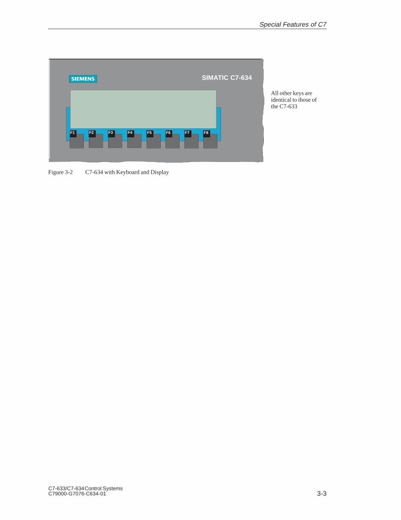
All other keys areidentical to those ofthe C7-633
SIMATIC C7-634
F1 F2 F3 F4 F5 F6 F7 F8
Figure 3-2 C7-634 with Keyboard and Display
Special Features of C7

3-4C7-633/C7-634 Control Systems
C79000-G7076-C634-01
3.2 Selecting a C7 CPU Operating Mode
You select the CPU operating modes RUN-P, RUN, STOP, and MRES asfollows:
Each time the mode selector key is pressed, the CPU mode changes. The keymust remain pressed for at least 500 ms for the mode change to take placeand the corresponding LED to light up.
To prevent an uncontrolled C7 CPU operating mode transition during controloperation, the key function can be activated or deactivated via an externalauthorization input. When the authorization input is activated, operatingmode selection is active and the current CPU mode is displayed by an LED.When the authorization input is deactivated, all status LEDs are off.
The authorization input is located on the same connector as the C7 powersupply (see Section 2.4).
Authorization activated: A+
AI
bridged
Authorization deactivated: A+
AI
open
Changing theC7 CPU OperatingMode
Special Features of C7

3-5C7-633/C7-634 Control SystemsC79000-G7076-C634-01
Mode Key Explanation / Procedure
RUN-P
(R-P)
The C7 CPU processes the user program.
Programs and data can be:
Read out from the C7 CPU with theprogramming device (C7 PG)
Downloaded to the C7 CPU and changedthere (PG C7).
RUN
(R)
The C7 CPU processes the user program.
Programs and data can be:
Read out from the C7 CPU with theprogramming device (C7 PG).
cannot be downloaded to the C7 CPU andchanged there (PG C7).
STOP
(S)
The C7 CPU does not process the userprogram.
Programs can be:
Read out from the C7 CPU with theprogramming device (C7 PG)
Downloaded to the C7 CPU and changedthere (PG C7).
Note:
The STOP mode is only valid for the C7 CPUand not for the C7 OP. It is possible to continueworking with the C7 OP.
MRES
(M)
Memory Reset
Executing a memory reset on the C7 CPU(clear memory, reload user program from flashmemory if a memory card is inserted) requires aspecial sequence of operations with the modesSTOP and MRES:
1. Select STOP mode by pressing the DOWNkey. The key must remain pressed for atleast 300 ms for the transition to take place.The key LED “S” and the CPU status LED“STOP” light up.
2. Select the mode MRES by keeping theDOWN key depressed. The key LED “M”lights up. Immediately after the second timethe CPU status LED “STOP” lights up,release the key briefly and press it again.After flashing briefly, it then remains lit.
Note:If data were deleted during the memory resetwhich were required by the C7 OPconfiguration, the C7 OP reports this using anerror message.
Special Features of C7

3-6C7-633/C7-634 Control Systems
C79000-G7076-C634-01
3.3 DI/DO Status Displays
The DI/DO status display is not a system function but a configured image ofthe C7 OP. You can create the DI/DO status display image yourself or copy itfrom the standard configuration supplied with ProTool (image name:Z_DI_DO).
The values represented are read as a direct process image of the digitalinputs and an internal process image of the digital outputs of the digitalC7 I/O and displayed in binary format (BIN).
Note that the last state set by the program is displayed, although the realprocess state of the digital outputs is 0 when the C7 CPU is in STOP mode.
The following data are supplied:
= Anwahl der
10101010 1.7-1.0
DI:11101110 0.7-0.0
DO:11101110 0.7-0.010101010 1.7-1.0
F1 F2 F3 F4
Figure 3-3 DI/DO Status Display on a C7-633 P
Table 3-1 Explanation of the DI/DO Display in Figure 3-3
Position Explanation
Signal status of the DI/DO
1 DI/DO set
0 DI/DO reset
Pin no. from - to
Note
The values of the digital I/O are read in and displayed every 400 ms. Anychanges which occur between these times are not displayed.
The DI/DO image of the standard configuration accesses the digital I/Os ofthe first configured programmable controller. Therefore, the firstprogrammable controller in the list should always be the C7 CPU. Otherwiseit is necessary to adapt the programmable controller access for the image.
Configuring theDI/DO StatusDisplay
C7 CPU Access
Special Features of C7
3-7C7-633/C7-634 Control SystemsC79000-G7076-C634-01
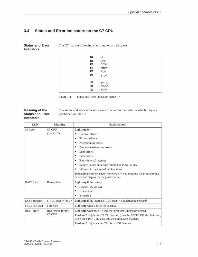
3.4 Status and Error Indicators on the C7 CPU
The C7 has the following status and error indicators:
SF
BATFDC5V
FRCERUN
STOP
SF-IMSF-DPBUSF
Figure 3-4 Status and Error Indicators on the C7
The status and error indicators are explained in the order in which they arepositioned on the C7.
LED Meaning Explanations
SF (red) C7 CPUgroup error
Lights up for
Hardware faults
Firmware faults
Programming errors
Parameter assignment errors
Math errors
Time errors
Faulty internal memory
Battery failure or backup missing on POWER ON
I/O error in the internal I/O functions
To determine the error/fault more exactly, you must use the programmingdevice and display the diagnostic buffer.
BATF (red) Battery fault Lights up if the battery
Has too low voltage
Is defective
Is missing
DC5V (green) 5 VDC supply for C7 Lights up if the internal 5 VDC supply is functioning correctly
FRCE (yellow) Force job Lights up when a force job is active
RUN (green) RUN mode for theC7 CPU
Lights up when the C7 CPU user program is being processed.
Flashes (2 Hz) during C7 CPU startup (then the STOP LED also lights up;when the STOP LED goes out, the outputs are enabled).
Flashes (2 Hz) when the CPU is in HOLD mode.
Status and ErrorIndicators
Meaning of theStatus and ErrorIndicators
Special Features of C7

3-8C7-633/C7-634 Control Systems
C79000-G7076-C634-01
LED ExplanationsMeaning
STOP (yellow) STOP mode for theC7 CPU
Lights up when the C7 is not processing a CPU user program.
Flashes in 1-second intervals if the C7 CPU requires a memory reset(MRES).
SF-IM (red) Interface modulegroup error
Lights up when the connection between the C7 and the expansion rack isfaulty.
The following table explains the meaning of the LEDs which are assigned tothe PROFIBUS DP. Refer also to Chapter 11 in the manual /70/.
SF-DP(red)
BUSF(green)
Meaning Remedy
On On Bus fault (physical fault) Check the bus cable for short circuit or wirebreak
DP interface fault
Different transmission rates inmulti-master operation
Evaluate diagnostics, reconfigure or correcterrors if necessary
On Flashing Station failed Check the bus cable is connected correctly,check for short circuits or wire breaks
At least one of the assigned slaves cannotbe addressed
Wait until the C7 has completed its startup
If flashing does not cease, check the DPslaves and evaluate diagnostics
On Off DP configuration missing or faulty (also ifCPU was not set as DP master)
Evaluate diagnostics, reconfigure or correcterrors if necessary
Off Off No error
Display Elementsfor PROFIBUS
Special Features of C7

4-1C7-633/C7-634 Control SystemsC79000-G7076-C634-01
Communication between the CPU and theOperator Panel
This chapter provides you with information on configuration parameters thatare necessary for the communication between the C7 OP and the C7 CPU.
The communication is achieved using two data areas:
The user data area
and/or
The interface area.
The functions, structure, and special features of the various user data areasand the interface areas are described in this chapter.
For those who are not yet familiar with OPs, we recommend the manual FirstSteps with ProTool/Lite.
Section Description Page
4.1 Configured Communications Parameters 4-2
4.2 Overview of User Data Areas 4-3
4.3 Event and Alarm Messages 4-4
4.4 Keyboard and LED Image 4-8
4.4.1 System Keyboard Image 4-9
4.4.2 Function Keyboard Image 4-10
4.4.3 LED Image 4-11
4.5 Screen Number Area 4-12
4.6 User Version 4-13
4.7 Interface Area 4-14
4.7.1 Control and Checkback Bits 4-15
4.7.2 Data Areas in the Interface Area 4-17
4.8 Recipes 4-19
4.8.1 Transferring Data Records 4-20
4.8.2 Addressing Recipes and Data Records, and the RequisiteData Areas
4-20
4.8.3 Synchronization during Transfer - Normal Case 4-21
4.8.4 Synchronization during Transfer - Special Cases 4-22
4.9 Notes on Optimization 4-23
4.10 Data Exchange via the Interface Area 4-24
4.10.1 Example of How to Activate a Control Job 4-31
In This Chapter
ChapterOverview
4

4-2C7-633/C7-634 Control Systems
C79000-G7076-C634-01
4.1 Configured Communications Parameters
In the configuration software, the following parameters are to be set forcommunication via the MPI:
Note
The following parameters are already assigned generally applicable defaultvalues and need not be modified unless the C7 is used in connection withany other S7, C7, or OP units in a network.
Parameter Explanation
CPU type CPU in programmable controllerThe S7-300 is to be set for the C7 CPU. If further CPUs areconnected, they must be set with S7-300 or S7-400.
CPU address MPI address of the C7 CPU in the network configuration. Thedefault address is 2. The address can be freely assigned. It mustbe unique in a network.
Slot/rack Here you must set the slot and rack. For the C7 CPU, thesetting is:Slot 2Rack 0
C7 OP address MPI address of the C7 OP in the network configuration. Theaddress can be freely assigned. It must be unique in thenetwork configuration. The default value is address 1.
Interface Here, you determine which interface of the OP the C7 CPU isconnected to.
Transmission rate The data transfer rate between the C7 OP and the C7 CPU canbe set between 19.2 Kbps and 1.5 Mbps.
All settings can be made with ProTool and ProTool/Lite under the menucommand System → PLC .
Parameters
Configuration Tool
Communication between the CPU and the Operator Panel

4-3C7-633/C7-634 Control SystemsC79000-G7076-C634-01
4.2 Overview of User Data Areas
User data areas are used to exchange data between the C7 CPU and theC7 OP. It is by means of these data areas that the C7 CPU and the C7 OPcommunicate.
The communication process consists of the C7 OP and the user programalternately writing and reading information into and out of the data areas.Upon evaluation of the data, the C7 CPU and the C7 OP are triggered intothe various actions.
The user data areas can reside in any required memory area in the C7 CPU.
The following user data areas are possible:
Event messages
Alarm messages
Control jobs
Recipes
System keyboard image
Function keyboard image
LED image
Cyclic intervals (C7-634 only)
Date and time
Screen number area
User version
User Data Areas
Functionality
Communication between the CPU and the Operator Panel

4-4C7-633/C7-634 Control Systems
C79000-G7076-C634-01
4.3 Event and Alarm Messages
Messages are triggered by setting a bit in one of the message areas in theC7 CPU. The location of the message area is defined by the configurationtool. The corresponding area must also be defined in the C7 CPU.
As soon as the bit in the event or alarm message area of the C7 CPU is setand transferred to the C7 OP, the message is recognized as having “arrived”.
Conversely, after resetting the same bit in the C7 CPU, the message isregistered in the C7 OP as having “departed”.
Table 4-1 represents the number of message areas for event and alarmmessages and alarm acknowledgement areas, as well as the total length of allareas, for both the C7-633 and the C7-634.
Table 4-1 Message Areas of the C7 OP
Device Event message area Alarm message area and alarmmessage acknowledgement area
Number Length words Number ofeach type
Total length of eachtypewords
C7-633 4 32 4 32
C7-634 4 64 4 64
A message can be configured for every bit in the configured message area.The bits are assigned to the message numbers in ascending sequence.
Example:
The following event message area is configured for the C7 CPU:
DB 60 Address 42 Length 5 (in words)
Figure 4-1 shows the assignment of all 80 (5 x 16) message numbers to theindividual bit numbers in the control event message area.
The assignment follows automatically in the C7 OP.
Figure 4-1 Assignment of Message Bit and Message Number
MessageTriggering
Message Areas
Message Bit andMessage NumberAssignment
Communication between the CPU and the Operator Panel

4-5C7-633/C7-634 Control SystemsC79000-G7076-C634-01
As alarm messages indicate faulty behavior of some sort, these must beacknowledged. Acknowledgement follows either by:
Taking appropriate action on the C7 or
Setting a bit in the acknowledgement area of the C7 CPU.
If the C7 CPU is to be informed about an acknowledgement of an alarmmessage at the C7 OP itself, or if the acknowledgement should be given bythe C7 CPU, the corresponding acknowledgement areas are to be configuredin the C7 CPU:
Acknowledgement area C7 OP C7 CPU:The programmable controller is informed when an alarm message isacknowledged by an operation at the OP.
Acknowledgement area C7 CPU C7 OP:The alarm message is acknowledged via the C7 CPU.
These acknowledgement areas are to be allocated in the configuration; -when using ProTool and ProTool/Lite, under “area pointers”. Figure 4-2shows schematically the individual alarm message and acknowledgementareas
Internal processing /linking
Alarm message area
Acknowledgement areaC7 CPU C7 OP
Acknowledgement areaC7 OP C7 CPU
Figure 4-2 Alarm Message and Acknowledgement Areas
Every alarm message has a message number. To this message number, thesame bit of the alarm message area and the bit multiplying of theacknowledgement area are assigned. This is also valid for more than oneacknowledgement area, if the length of the previous acknowledgement areadoes not encompass the entire length of the alarm message area. Figure 4-3clarifies this situation.
Acknowledge bit for alarm message no. 49
Alarm message no. 1
Alarm message no. 49
Acknowledge bit for alarm message no. 1
Figure 4-3 Assignment of Acknowledge Bit and Message Number
Acknowledgement
AcknowledgementArea
Assignment ofAcknowledgementBit to MessageNumber
Communication between the CPU and the Operator Panel

4-6C7-633/C7-634 Control Systems
C79000-G7076-C634-01
One of the bits set in the C7 CPU area, causes the acknowledgement of thecorresponding alarm message at the C7 OP. Reset this bit when you reset thebit in the alarm message area. Figure 4-4 shows the timing diagram.
The acknowledgement area C7 CPU C7 OP
Must be immediately connected to the relevant alarm message area
Must have exactly the same polling time and
Can have the same maximum length as the corresponding alarm messagearea.
If the acknowledgement area C7 CPU → C7 OP is not physically locatedbehind the alarm message area, the system message $655 is issued when thedevice starts up.
Alarm message area
Acknowledgementarea C7 CPU →C7 OP Acknowledgement
via C7 CPU
Figure 4-4 Pulse Diagram for Acknowledgement Area C7 CPU → C7 OP
If a bit is set in the alarm message area, the CP OP sets the corresponding bitin the acknowledgement area. If an alarm message is acknowledged at theC7 OP, the corresponding bit is set in the acknowledgement area C7 OP
C7 CPU. In this way, the S7 can recognize that the alarm message has beenacknowledged.
The acknowledgement area C7 OP C7 CPU can have the same maximumlength as the corresponding alarm message area.
Alarm message area
Acknowledgement areaC7 OP → C7 CPU
Acknowledgementvia C7 OP
Figure 4-5 Pulse Diagram forAcknowledgement Area C7 OP → C7 CPU
AcknowledgementArea C7 CPU →C7 OP
AcknowledgementArea C7 OP C7 CPU
Communication between the CPU and the Operator Panel

4-7C7-633/C7-634 Control SystemsC79000-G7076-C634-01
The acknowledgement areas may not be larger than the corresponding alarmmessage area. It can, however, be configured to be smaller if it is notnecessary to acknowledge every alarm message. Figure 4-6 clarifies thiscase.
Alarm message area Reduced alarm messageacknowledgement area
Alarm messagesthat cannot beacknowledged
Alarm messagesthat can beacknowledged
Figure 4-6 Reduced Acknowledgement Area
Note
Allocate important alarm messages, whose acknowledgement is to besignaled to the C7 CPU in the alarm message area from bit 0 in ascendingorder!
The two related bits in the alarm message area and the acknowledgementarea must not be set simultaneously.
Size of the AcknowledgementAreas
Communication between the CPU and the Operator Panel

4-8C7-633/C7-634 Control Systems
C79000-G7076-C634-01
4.4 Keyboard and LED Image
Key actions on the C7 OP can be transferred to the C7 CPU and evaluatedthere. In this way, actions can be triggered in the C7 CPU (for instance,switching on a motor).
The LEDs in the C7’s function keys can be controlled from the C7 CPU. Inthis way, active LEDs can be used in different situations to signal to theoperator which key they should press.
In order to make use of this function, you must:
Set up corresponding data areas (images) in the C7 CPU
Specify these data areas as “area pointers” during the configuration
Assign the bits from the “area pointers” to these data areas on configuringthe function keys.
The keyboard images are transferred spontaneously to the C7 CPU. Thatmeans the transfer always happens if a change is registered at the C7 OP. Inthis case you do not need to configure a polling time. A maximum of twosimultaneous key actions can be transferred at one time.
All keys (except SHIFT key)
As long as the corresponding key is pressed, the assigned bit in thekeyboard image has the value 1, otherwise it has the value 0.
SHIFT key
When the SHIFT key is first pressed, the assigned bit in the keyboardimage receives the value 1. This state remains even after releasing thekey until the SHIFT key is pressed again.
Application
Prerequisite
Transfer
Value Allocation
Communication between the CPU and the Operator Panel

4-9C7-633/C7-634 Control SystemsC79000-G7076-C634-01
4.4.1 System Keyboard Image
The system keyboard image is a data area with a fixed length of two datawords.
Every key of the system keyboard is assigned exactly one bit in the systemkeyboard image, with the exception of the cursor keys.
The system keyboard image must also be specified as “area pointer, type:system keyboard” in the configuration. This image can be assigned once onlyand in one CPU.
Keyboard image:
+$&!&$)%"(
'(*$&
#*$&
,
Bit number
Note
Unused bits may not be overwritten by the user program.
The keyboard group bit serves as the control bit. It is set to the value 1 foreach transfer of the keyboard image from the C7 OP to the C7 CPU. Afterevaluation of the data area by the user program, it should be reset.
You can determine whether a block has been transferred again by regularlyreading the group bits with the user program.
Layout
Keyboard GroupBit
Communication between the CPU and the Operator Panel

4-10C7-633/C7-634 Control Systems
C79000-G7076-C634-01
4.4.2 Function Keyboard Image
The image of the function keyboard can be categorized into separate dataareas:
Maximum number of data areas - 4
Total length of all data areas (words) - 4
The assignment of the individual keys to the data area bits is defined whenthe function keys are configured. The number within the image area isdeclared for every key.
The function keyboard image must also be specified in the configuration,under “area pointer, type: function keyboard”.
The most significant bit in the last data word of every data area is thekeyboard group bit. It serves as a control bit. This bit is set to 1 for everytransfer of the keyboard image. After evaluation of the data area by the userprogram, the keyboard group bit should be reset.
You can determine whether a block has been transferred again by regularlyreading the group bits with the user program.
Data Areas
Key Assignment
Keyboard GroupBit
Communication between the CPU and the Operator Panel

4-11C7-633/C7-634 Control SystemsC79000-G7076-C634-01
4.4.3 LED Image
The LED image can be categorized into separate data areas.
Maximum number of data areas: 4 (for example, 4 different data areas invarious CPUs)
Total length of all data areas (words) 8:
The LED image must also be specified under “area pointer, type: LEDimage” in the configuration.
The assignment of the individual LEDs to the data area bits is defined whenthe function keys are configured. The bit number within the image area isdeclared for every LED.
The K keys in the C7 OPs have two-colored LEDs (red and green).
The bit number (n) denotes the first of two consecutive bits, which cancontrol four different LED states in total:
Bit n + 1 Bit n LED Function
0 0 Off
0 1 Flashing red
1 0 Permanently red
1 1 Permanently green
Data Areas
LED Assignment
Communication between the CPU and the Operator Panel

4-12C7-633/C7-634 Control Systems
C79000-G7076-C634-01
4.5 Screen Number Area
The C7 OP stores information concerning the image displayed on the C7 OPin the screen area number.
It is thus possible to transfer information about the current display contentsfrom the C7 OP to the C7 CPU, and from there, to trigger certain reactions,for example, displaying another image.
If the screen number area is to be used, it must be specified as an “areapointer” in the configuration. It can only be stored once and in one C7 CPU.
The screen number area is transferred spontaneously to the controller. Thatmeans the transfer always happens if a change is registered at the C7 OP. Inthis case you do not need to configure a polling time.
The screen number area is a data area with a fixed length of 2 data words.
The layout of the screen number area for the C7 OP in the memory of thecontroller is represented below.
Current screen type
Current entry number Current input field number
Current screen number
7 0 7 0
1st word
2nd word
Entry Assignment
Current screen type 1: Image
2: Recipe
3: Special image
Current screen/recipe number 1 to 99
Current entry number 1 to 99
Current input field number 0 to 80: Entry number
All bytes of the screen number area are assigned with FF in the messagelevel and for the display of a contents directory.
For special screens the screen number area is assigned as follows:
0 77 0
3 Special screen number
FFH Current input field number
1st word
2nd word
Application
Requirement
Layout
Communication between the CPU and the Operator Panel

4-13C7-633/C7-634 Control SystemsC79000-G7076-C634-01
4.6 User Version
You can check whether the C7 OP is connected to the right controller onstartup.
The C7 OP compares a value stored in the C7 CPU with the configuredvalue. This ensures that the configuration data are compatible with the C7CPU. If the values do not match, the system message $653 is displayed onthe C7 OP and the device is restarted.
To use this function, preset the following values when configuring theC7 OP:
Version number of the configuration (value between 1 and 255) underSystem → Settings
Data type and address of the value stored in the controller for the version: System → Area Pointers,Select User Version in the Type: field.
Verwendung
Communication between the CPU and the Operator Panel

4-14C7-633/C7-634 Control Systems
C79000-G7076-C634-01
4.7 Interface Area
The interface area is only necessary for the C7 CPU if its functions are to beused or evaluated by the C7 CPU.
The interface area must be configured if you want to use the followingfunctions:
– Send control jobs to the C7 OP
– Synchronize date and time between the C7 CPU and the C7 OP
– Evaluate coupling identifier
– Recipes (transferring data records)
– Recognize C7 OP startup in the C7 CPU program
– Evaluate the C7 OP operating mode in the C7 CPU program
– Evaluate the C7 OP’s ready bit in the C7 CPU program
– Set cyclic interrupts (C7-634 only)
Figure 4-7 shows the layout of the interface area. You can define the interfacearea in a data block or a memory area. The address of the interface area shouldbe specified in the configuration. This is necessary so that the OP knows whereto put the data.
The interface area should be created once per CPU.
Interface area:
7 0Address
Control / checkback bits
n+0
n+4
Job area
n+12
n+14
n+25
Coupling identifier
Time
Date
n+13Reserved
n+18
n+15
n+21
Reserved
Reserved
Reservedn+26
n+31
Cyclic interrupt bits
Figure 4-7 Layout of the Interface Area for the C7 CPU
Overview
Layout of theInterface Area
Communication between the CPU and the Operator Panel

4-15C7-633/C7-634 Control SystemsC79000-G7076-C634-01
4.7.1 Control and Checkback Bits
Three bytes are available in the interface area for the control and checkbackbits. Bytes n+0 and n+1 are used to coordinate between the C7 OP and theC7 CPU. Byte n+3 is required for the transfer of data records and indirectvariables.
Byte n+0, n+1, and n+3 are described below.
The structure of byte n+0 is shown below. The diagram is followed by a description of the individual bits.
7 6 5 4 3 2 1 0Address
n+0
Time
Date
Cyclic interrupt bit
Bits 5-6 Date/time 1 = New
The transfer of the date and time from the C7 OP to the C7 CPUcan be initiated by means of control job 41. These bits are set bythe C7 OP if a new date or a new time is transferred. The bits mustbe reset in the control program after the date or time has beenevaluated.
Bit 7 Cyclic interrupt bit: 1 = New
The cyclic interrupt bit is possible only for the C7-634.If the C7-634 has set a new cyclic interrupt bit in the interface area,it also sets the corresponding bit in the control and checkback bits.You therefore need only scan this bit to detect a change in the cyclicinterrupt bit. Following evaluation, the bit has to be reset in the S7program.
The following diagram shows the layout of byte n+1. Afterwards follows thedescription of the individual bits.
7 6 5 4 3 2 1 0Address
n+1
C7 OP ready bit
C7 OP operating mode
C7 OP startup
Introduction
Description of Byte n+0
Description of Byte n+1
Communication between the CPU and the Operator Panel

4-16C7-633/C7-634 Control Systems
C79000-G7076-C634-01
Bit 0 C7 OP startup1 = C7 OP has been started
Bit 0 is reset by the C7 OP following startup. You can reset the bitin the C7 CPU program and thus recognize when the C7 OP isbeing restarted.
Bit 1 C7 OP operating mode1 = C7 OP in offline mode0 = C7 OP in normal mode
Bit 1 is set if the operator switches the C7 OP to offline. The bithas a value 0 in an online condition.
Bit 2 C7 OP ready bitThe C7 OP inverts the ready bit within 1 second. In the C7 CPUprogram, you can recognize whether a connection to the C7 OPexists.
Byte n+3 serves to synchronize the transfer of data records and indirectvariables. The meanings of the individual bits are described below. Exactlyhow the transfer works is described in Section 4.8.3.
Bit 0 1 = Data mailbox is disabled (set only by the C7 OP)0 = Data mailbox is enabled
Bit 1 1 = Data record/variable is faulty
Bit 2 1 = Data record/variable is correct
Bit 3 1 = Data transfer completed
Bit 4 1 = Request data record/variable
Bit 5 1 = C7 OP should read data mailbox
Bit 6 1 = Request data mailbox disable
Bit 7 1 = C7 OP has read data mailbox (with transfer C7 CPU→C7 OP)
Description of Byte n+3
Communication between the CPU and the Operator Panel

4-17C7-633/C7-634 Control SystemsC79000-G7076-C634-01
4.7.2 Data Areas in the Interface Area
In this section, the structure and use of the interface data areas are described.
The C7 CPU initiates an action to be carried out on the C7 OP by means ofthe job area. All other bytes are areas in which the C7 OP writes data. Theseareas can be evaluated by the C7 CPU program. The individual bytes aredescribed below.
Bytes n+4 to n+11:Control jobs can be passed on to the C7 OP via the job area. The actions onthe C7 OP are initiated in this way.
The job area consists of four words. In the first word of the job area is the jobnumber. In the other words, the job parameters are to be entered (maximum3). Figure 4-8 shows the general structure of a control job.
If the first word of the job area is not equal to zero, the C7 OP evaluates thecontrol job. After that, the C7 OP sets this data word to zero again. For thisreason, the parameters must first be entered in the job area and only then thejob number.
The possible control jobs are listed with job numbers and parameters inSection 4.10.
Byte n+13:The C7 OP enters the coupling identifier 0 for the multipoint interface inbyte 13.
Time = bytes n+15 to n+17Date = bytes n+21 to n+24The date and time can be transferred from the C7 OP to the C7 CPU viacontrol job 41.
The following screens show the structure of the data area. All inputs arecoded in Binary Coded Decimal (BCD).
Time:
07
Date:
Overview
Job Area
Coupling Identifier
Date and Time
Communication between the CPU and the Operator Panel

4-18C7-633/C7-634 Control Systems
C79000-G7076-C634-01
07
Bytes n+26 to n+31:A cyclic interrupt is a periodically recurring point in time (hourly, daily,weekly, annually) at which a predefined function is executed - for example:
Print message buffer or screen
Select screen.
When a cyclic interrupt is reached on the C7 OP, the corresponding bit is setin this area:
n + 26
n + 30
7 0Address
16
32
48
1
17
33
Cyclic Interrupt No.
70
Cyclic InterruptBits (C7-634 only)
Communication between the CPU and the Operator Panel

4-19C7-633/C7-634 Control SystemsC79000-G7076-C634-01
4.8 Recipes
A recipe is a group of variables for a fixed data structure. You set thisstructure in your configuration and assign data to it on the C7 OP. You cannotmodify the structure on the C7 OP later.
Since the data structure can be assigned several times, we refer to datarecords. These data records are stored (created), loaded, deleted, andmodified on the C7 OP. The data are stored on the C7 OP, thus savingmemory on the C7 CPU.
Using recipes insures that, when a data record is transferred to the C7 CPU,several items of data are transferred to the C7 CPU together and in asynchronized fashion.
Data records can be transferred from the C7 OP to the C7 CPU or from theC7 CPU to the C7 OP. You transfer data records from the C7 OP to theC7 CPU to set specific values on the C7 CPU - for example, to produceorange juice. In the same way, you can fetch data from the C7 CPU and storethem on the C7 OP as a data record to save, say, a favorable assignment ofvalues.
Note
Only variables are used to transfer data records. In order to transfer a datarecord from the data medium (flash) of the C7 OP to the C7 CPU, it mustfirst be loaded into the variables.
A special feature of recipes is that the data are transferred synchronously andcannot be inadvertently overwritten. To insure a coordinated procedure fortransferring data records, bits are set in the control and checkback byte 2 of theinterface area.
Overview
Transferring DataRecords
Synchronization
Communication between the CPU and the Operator Panel

4-20C7-633/C7-634 Control Systems
C79000-G7076-C634-01
4.8.1 Transferring Data Records
When a data record is written, the variables in the data record are writtendirectly to the defined addresses concerned. With direct reading, the variablesare read into the C7 OP from the target memories of the C7 CPU.
With ProTool, the variables must have a direct link to the C7 CPU for directtransfer. Variables not having an assigned address on the C7 CPU are nottransferred.
4.8.2 Addressing Recipes and Data Records, and the Requisite Data Areas
During configuration, the recipe is given a name and a number. Both therecipe name and the recipe number can be seen on the C7 OP.
The data records you create on the C7 OP are similarly given a name and anumber.
When a data record transfer is initiated from the C7 OP to the C7 CPU, therecipe name and the data record number are transferred to the controllertogether with the data. For this, you have to create a data mailbox in thecontroller. Use the same specifications as were set in the configuration underArea Pointer. The values of the data record are written directly to theaddresses in the controller.
Data mailbox:
Data record numberReserved
Recipe numberReservedReserved
1st word2nd word3rd word4th word5th word
Definition
Adressing/Data areas
Communication between the CPU and the Operator Panel

4-21C7-633/C7-634 Control SystemsC79000-G7076-C634-01
4.8.3 Synchronization during Transfer - Normal Case
The control and checkback bits in the interface area synchronize data recordtransfer. A transfer is normally initiated by an operator input on the C7 OP.
Bit 0 1 = Data mailbox is disabled (set only by the C7 OP)0 = Data mailbox is enabled
Bit 1 1 = Data record/variable is faulty
Bit 2 1 = Data record/variable is correct
Bit 3 1 = Data transfer completed
Bit 4 1 = Request data record/variable
Bit 5 1 = C7 OP should read data mailbox
Bit 6 1 = Request data mailbox disable
Bit 7 1 = C7 OP has read data mailbox(with transfer C7 CPU → C7 OP)
Description:
Byte n + 3 = Control and checkback bits in the interface area
The following description shows the procedure by which the C7 OP setssynchronizing bits and the manner in which the C7 CPU program has to reactto them.
Table 4-2 Procedure for Transmission
Step Explanation
1 Bit 0 is checked by the C7 OP. If bit 0 is set to 1 (= data mailboxdisabled), the transfer is terminated with a system error message. If bit 0 isset to 0, the C7 OP sets the bit to 1.
2 The C7 OP enters the identifications in the data mailbox.
With an indirectly transferred data record, the data record values are alsowritten to the data mailbox. With a directly transferred data record, thevalues of the variables are written to the configured address.
3 The OP sets bit 3 to 1 (= data transfer terminated).
4 The data record or the variable can be evaluated in the control program.You then have to acknowledge in the control program whether the transferwas correct or faulty.Correct: bit 2 is set to 1Faulty: bit 1 is set to 1
5 Reset bit 0 in the control program.
6 The C7 OP resets the bits set in step 3 and step 4.
Transferring DataRecords
Transfer C7 OP →C7 CPU(Initiated onC7 OP)
Communication between the CPU and the Operator Panel

4-22C7-633/C7-634 Control Systems
C79000-G7076-C634-01
4.8.4 Synchronization during Transfer - Special Cases
Make sure that the values of the data record are only read by the internal datamedium. The current values are not relevant to the data record transfer.
Step Explanation
1 In the control program, request the data mailbox disable by setting bit 6 to1.
2 If a disable is possible, the C7 OP sets bit 0 to 1 and simultaneously resetsbit 6 to 0.
3 In the control program, inform the C7 OP via the data mailbox which datarecord it should transfer. To do this, enter the identifications of the datarecord in the data mailbox.
4 Set bit 4 to 1 (= request data via data mailbox) in the control program.
5 The C7 OP reads the data mailbox.
6 The C7 OP resets bit 4 and transfers the data record or the variable asdescribed for case 1 from step 2 onwards.
Direct transfer from the C7 CPU to the C7 OP always takes place withoutcoordination. The values are read directly from the address. Variables withoutaddresses are ignored.
The values are written from the C7 CPU into the internal data medium.
Step Explanation
1 In the S7 program, request the data mailbox disable by setting bit 6 to 1.
2 If a disable is possible, the C7 OP sets bit 0 to 1 and simultaneously resetsbit 6 to 0.
3 In the S7 program, inform the C7 OP via the data mailbox which datarecord it should fetch by entering the recipe number and data record num-ber in the mailbox.
4 Set bit 5 to 1 (= C7 OP is to read data mailbox).
5 When the C7 OP has fetched the data record, it sets bit 7 to 1 (= C7 OP hasread data mailbox). By setting bit 7, the C7 OP specifies that the read pro-cess is terminated.
6 Set bit 7 to 0.
A data record can be transferred from the C7 OP to the C7 CPU via controljob No. 70. Control job 69 initiates transfer from the C7 CPU to the C7 OP.
Transfer C7 OP →C7 CPU(Initiated byC7 CPU)
TransferC7 CPU → C7 OP(Initiated byC7 OP)
Transfer C7 CPU → C7 OP(Initiated byC7 CPU)
Transfer UsingControl Jobs
Communication between the CPU and the Operator Panel

4-23C7-633/C7-634 Control SystemsC79000-G7076-C634-01
4.9 Notes on Optimization
The structure of the user data areas described in Section 4.3 and theconfigured polling times in the area pointers are significant factors for theupdate times that can actually be achieved. The update time is the pollingtime plus the transfer time plus the processing time.
To achieve an optimal update time, the following points should be observedduring configuration:
Configure the individual data areas as large as necessary, but as small aspossible.
Define the data areas which belong together contiguously. The actualupdate time improves if you configure one large area as opposed toseveral small areas.
The total performance is unnecessarily compromised if the polling timesare too small. Set the polling time according to the changing speed of theprocess values. The change in temperature of an oven for example, issignificantly more sluggish than the change of rotary speed in anelectrical drive.
The approximate value for the polling time is around 1 second.
Avoid cyclic transfer of the user data areas (polling time 0) if necessary inorder to improve the update time. Instead of this use the control jobs totransfer the user data areas as required according to events.
Place the variables of a message or a screen without gaps in one dataarea.
In order that changes in the C7 CPU are recognized by the C7 OP, theymust at least be pending during the actual polling time.
Decisive Factors
Communication between the CPU and the Operator Panel

4-24C7-633/C7-634 Control Systems
C79000-G7076-C634-01
4.10 Control Jobs and Their Parameters
Using control jobs, functions on the C7 OP can be triggered by the controlprogram, such as:
– Displaying screens
– Setting the time and date
– Changing general settings
A control job is identified by its job number. Up to three parameters can betransferred depending on the control job.
A control job comprises four data words. The first data word contains the jobnumber. Depending on the function, up to three parameters can be passed indata words 2 to 4. Figure 4-8 shows the general structure of a control job.
Figure 4-8 Structure of a Control Job
Description
Control Job
Communication between the CPU and the Operator Panel

4-25C7-633/C7-634 Control SystemsC79000-G7076-C634-01
The following table lists all possible control jobs with their parameters. Thecolumn No. gives the job number for the controller. Control jobs can only betriggered by the controller when the C7 is in online operation.
No. Function
3 Hardcopy
Parameters 1, 2, 3 -
5 Select contents directory
Parameter 1 1: Contents: screens, display2: Contents: recipes, display4: Contents: print screens5: Contents: print recipes7: Contents: recipes, data record transfer
Parameters 2, 3 -
7 Print all screens
Parameters 1, 2, 3 -
10 Print recipe with all data records
Parameter 1 Recipe number (1 to 99)
Parameters 2, 3 -
11 Select special screens
The following screens integrated in the firmware can be selected via their (fixed)object number.
Parameter 1 LB: Cursor lock (0: off, 1: on)RB: Special screen number
Alarm message buffer1 Buffer output2 Output number of messages3 Overflow warning on/off4 Delete buffer yes/no
Event message buffer5 Buffer output6 Output number of messages7 Overflow warning on/off8 Delete buffer yes/no
Programming device functions25 Status VAR26 Modify VAR
Special functions30 Language, brightness (contrast)31 Change operating mode
Settings35 Set time/date36 Internal interface (C7-633: RS 232;
C7-634: IF1)37 Submodule interface (C7-633: TTY; C7-634: IF2)38 Printer parameters40 Message type
Message texts45 Display alarm message texts46 Display event message texts
Listing
Communication between the CPU and the Operator Panel

4-26C7-633/C7-634 Control Systems
C79000-G7076-C634-01
No. Function
System messages50 Output system message buffer
Passwords55 Login56 Password input
Parameters 2, 3 -
12 Message log on/off
Parameter 1 0: Off1: On
Parameters 2, 3 -
13 Change language
Parameter 1 0: 1st language1: 2nd language2: 3rd language
Parameters 2, 3 -
14 Set time (BCD-coded)
Parameter 1 LB: -RB: Hours (0 to 23)
Parameter 2 LB: Minutes (0 to 59)RB: Seconds (0 to 59)
Parameter 3 -
15 Set date (BCD-coded)
Parameter 1 LB: -RB: Weekday (1 to 7: Sunday to Saturday)
Parameter 2 LB: Date (1 to 31)RB: Month (1 to 12)
Parameter 3 LB: Year
16 Parameters for internal interface (C7-633:RS 232; C7-634: IF1)
Parameter 1 Value for parameter 2
Transmission rate (only for printer)0: 300 bps1: 600 bps2: 1200 bps3: 2400 bps4: 4800 bps5: 9600 bps6: 19200 bps
Data bits (only for printer)0: 7 data bits1: 8 data bits
Stop bits (only for printer)0: 1 stop bit1: 2 stop bits
Parity (only for printer)0: Even1: Odd2: None
Communication between the CPU and the Operator Panel
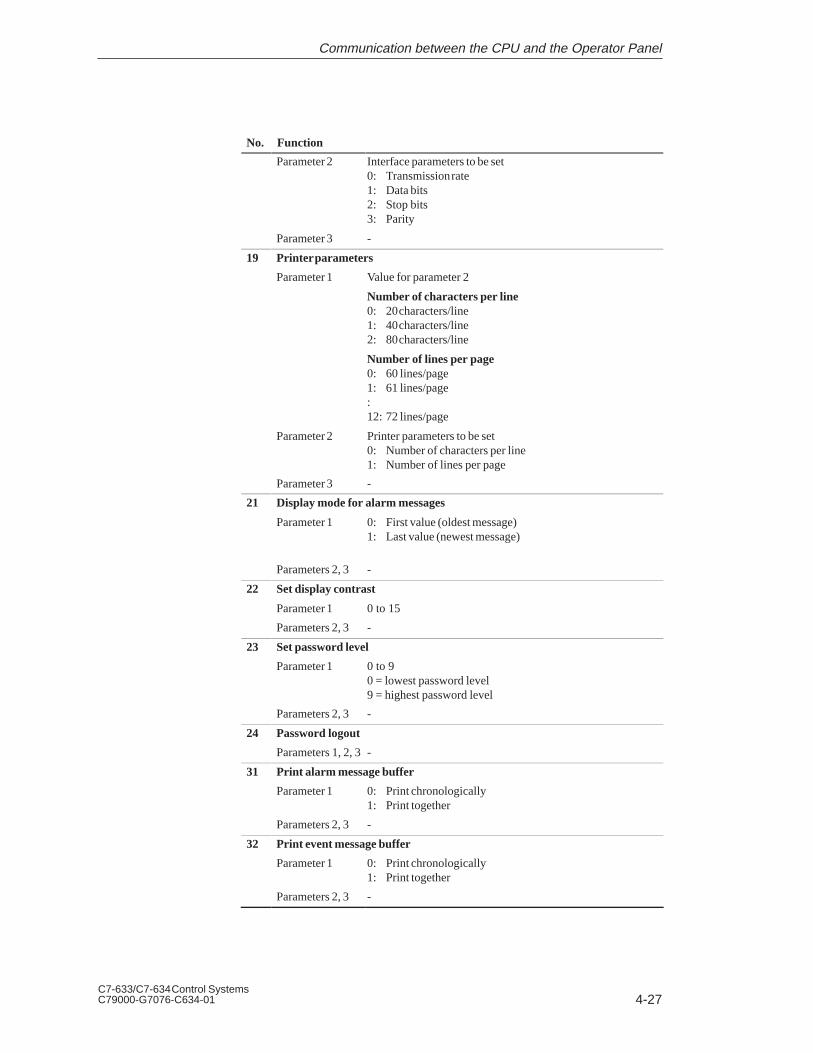
4-27C7-633/C7-634 Control SystemsC79000-G7076-C634-01
No. Function
Parameter 2 Interface parameters to be set0: Transmission rate1: Data bits2: Stop bits3: Parity
Parameter 3 -
19 Printer parameters
Parameter 1 Value for parameter 2
Number of characters per line0: 20 characters/line1: 40 characters/line2: 80 characters/line
Number of lines per page0: 60 lines/page1: 61 lines/page:12: 72 lines/page
Parameter 2 Printer parameters to be set0: Number of characters per line1: Number of lines per page
Parameter 3 -
21 Display mode for alarm messages
Parameter 1 0: First value (oldest message)1: Last value (newest message)
Parameters 2, 3 -
22 Set display contrast
Parameter 1 0 to 15
Parameters 2, 3 -
23 Set password level
Parameter 1 0 to 90 = lowest password level9 = highest password level
Parameters 2, 3 -
24 Password logout
Parameters 1, 2, 3 -
31 Print alarm message buffer
Parameter 1 0: Print chronologically1: Print together
Parameters 2, 3 -
32 Print event message buffer
Parameter 1 0: Print chronologically1: Print together
Parameters 2, 3 -
Communication between the CPU and the Operator Panel

4-28C7-633/C7-634 Control Systems
C79000-G7076-C634-01
No. Function
37 Overflow warning for event messages on/off
Parameter 1 0: Off1: On
Parameters 2, 3 -
38 Overflow warning for alarm messages on/off
Parameter 1 0: Off1: On
Parameters 2, 3 -
41 Transfer date/time to C7 CPU
At least 5 seconds should lie between two jobs otherwise the C7 OP will beoverloaded.
Parameters 1, 2, 3 -
43 Fetch C7 CPU event message bit area
Parameter 1 Area pointer no.: 1 to 4
Parameters 2, 3 -
44 Fetch C7 CPU alarm message bit area
Parameter 1 Area pointer no.: 1 to 4
Parameters 2, 3 -
45 Fetch C7 CPU acknowledgement area
Parameter 1 Area pointer no.: 1 to 4
Parameters 2, 3 -
47 Transfer LED area directly to C7 OP
Parameter 1 Area pointer no.: 1 to 4
Parameter 2 LED image: 1st word
Parameter 3 LED image: 2nd word
In contrast to control job no. 42 (fetch LED area from C7 CPU), the LED imageis directly transferred with the control job here, thus achieving faster control ofthe LEDs.
The specified LED area must not be configured larger than 2 DW.
48 Menu selection
Parameter 1 Menu number in the standard menu
1 Message level
Parameter 2 Menu item number0: First menu item1 to 20 Other menu items
Parameter 3 -
49 Delete event message buffer
Parameters 1, 2, 3 -
50 Delete alarm message buffer
Parameters 1, 2, 3-
Communication between the CPU and the Operator Panel

4-29C7-633/C7-634 Control SystemsC79000-G7076-C634-01
No. Function
51 Screen selection
Parameter 1 LB: Cursor lock (0: off; 1: on)RB: Screen number 1 to 99
Parameter 2 Entry number: 0 to 99(0 = cursor set to the first available entry)
Parameter 3 Field number:1 to 8 for C7-6331 to 32 for C7-634
Output fields are ignored in the serial numbering system.
Note:The input fields of an entry are numbered consecutively:
0 Entry number field1 First input field:n Last input field
The numbering of the input fields starts from 1 again for eachentry.
52 Print screen
Parameter 1 Screen number (1 to 99) in byte format
Parameters 2, 3 -
53 Select recipe
Parameter 1 LB: Cursor lock (0: off; 1: on)RB: Recipe number (1 to 99)
Parameter 2 Data record number (1 to 99)
Parameter 3 LB: Entry number (0 to 99)RB: Field number (0/1)
54 Print recipe
Parameter 1 Recipe number (1 to 99)
Parameter 2 Data record number (1 to 99)
Parameter 3 -
69 Transfer recipe data record from C7 CPU to C7 OP
Parameter 1 Recipe number (1 to 99)
Parameter 2 Data record number (1 to 99)
Parameter 3 0, 10: Data record is not overwritten1: Data record is overwritten
70 Transfer recipe data record from C7 OP to C7 CPU
Parameter 1 Recipe number (1 to 99)
Parameter 2 Data record number (1 to 99)
Parameter 3 -
71 Partial screen updating
Parameter 1 0: Off1: On
Parameters 2, 3 -
This job must only be triggered if no screen is selected.
Communication between the CPU and the Operator Panel

4-30C7-633/C7-634 Control Systems
C79000-G7076-C634-01
No. Function
72 Cursor positioning in current screen or recipe
Parameter 1 Entry number: 0 to 99
Parameter 2 Field number:1 to 8 for C7-6331 to 32 for C7-634
Parameter 3 Cursor lock (0: off; 1: on)
73 Cursor positioning in current special screen
Parameter 1 Field number (0 to 8)
Parameter 2 Cursor lock (0: off; 1: on)
Parameter 3 -
74 Keyboard simulation
Parameter 1 LB: Keyboard number1 Internal function keypad2 System keypad
RB: Password level0: Will be evaluated1: Will not be evaluated
Parameter 2 LB: Key code
Parameter 3 -
For keyboard simulation via a control job, take note of the transfer time from theC7 CPU to the C7 OP. For example, the acknowledgement of an alarm messageby keyboard simulation on the C7 CPU can lead to an undesired result if:
- The alarm message in question has already been acknowledged by an operation on the C7 or
- A new alarm message or system message arrives before the control job has been evaluated.
If the “cursor lock” parameter is equal to 1 in one of the jobs 11, 51, 53, 72,and 73, the selected input field can no longer be exited using the cursor keysor the ESC key. The cursor lock will only be disabled again by:
Repeating the job with the cursor lock = 0,
Another job which causes a change to the display on the screen.
If you try to exit the input field with the cursor lock activated, the systemmessage “$400 Invalid key pressed ” is displayed.
Jobs with CursorLock
Communication between the CPU and the Operator Panel

4-31C7-633/C7-634 Control SystemsC79000-G7076-C634-01
4.10.1 Example of How to Activate a Control Job
The following describes the procedure for activating a control job:
1. Set up the interface block (contains the interface area) in the C7 CPU (forexample, DB52).
2. In the configuration, enter the interface block (DB52) in the “areapointer”. This informs the C7 OP that this block exists.
3. The job is entered in the interface block by means of a C7 CPU program(see Figure 4-9).
4. The C7 OP reads the interface block and executes the job.
Program for control job 51 “Screen selection”
!!(#(&!$
&#$ #(&%&"(&'&##)"&#( $&$(#(&!$
#(&+$ #(&%&"(&#(&+#)"&#( $&$(#(&!$
!$ #(&%&"(&!#)"&#( $&$(#(&!$
#(&($#)"&#($&$( #(&!$ ($(*(($
Figure 4-9 Example of a C7 CPU Program
Procedure for Control Job
Communication between the CPU and the Operator Panel

4-32C7-633/C7-634 Control Systems
C79000-G7076-C634-01
Communication between the CPU and the Operator Panel
5-1C7-633/C7-634 Control SystemsC79000-G7076-C634-01
Communication Functions
Section Description Page
5.1 Introduction 5-2
5.2 Communication between C7/S7 Stations (MPI Subnet) 5-3
5.3 Communication within a C7/S7 Station (PROFIBUS DP or IM)
5-5
ChapterOverview
5

5-2C7-633/C7-634 Control Systems
C79000-G7076-C634-01
5.1 Introduction
The C7 offers the following methods of communication:
Communication between C7/S7 stations
The controller can exchange data with other stations in the MPI subnetvia the multipoint interface and the communication functionsX_SEND/X_RCV, X_GET, X_PUT (SFC65, SFC66, SFC67, SFC68) andglobal data.
Communication within a C7 station
The controller can read or write data to and from intelligent modules viathe PROFIBUS-DP interface or IM interface and the communicationfunctions I_GET (SFC72) and I_PUT (SFC73).
C7 ET 200 with e.g. FM 355
S7-300 station
PROFIBUS DP
MPI
S7-300 modules e.g. FM
C7
These communication system functions (SFCs) are described below. You willfind a detailed description in .
Communication Functions

5-3C7-633/C7-634 Control SystemsC79000-G7076-C634-01
5.2 Communication between C7/S7 Stations (MPI Subnet)
The communication SFCs offer the possibility of acknowledged dataexchange via non-configured S7 connections to other C7/S7 stations. Usingthese communication SFCs, you can reach all communication partners on theMPI subnet and transfer small quantities of data (max. 76 bytes).
From S7/M7/C7 CPUs you can also access variables in another C7/S7 CPU(X_PUT/X_GET).
The connections to the communication partners are established dynamicallywhen the SFC is called. A free connection resource in each of thecommunication partners will be required for this.
If there are no free connections resources available on the communicationpartners, no new connections can be established (temporary lack ofresources, indicated as SFC error class in RET_VAL).
The communication SFCs must not be deleted in RUN mode, otherwise anyconnection resources in use may not be able to be freed up (program changesonly in STOP).
The number of communication partners that can be reached one after theother is greater than the number of connections that can be set upsimultaneously (corresponds to a CPU-specific quantity, see ).
Communication is also possible if the communication partners are in otherS7 projects.
The communication SFCs do not require any additional user memory (forexample, in the form of instance data blocks).
The SFCs can have parameters assigned which means the block parameterscan be changed dynamically during program processing. This means differentcommunication partners can be reached in succession using one SFC.
On the server side, no SFCs are required in the user program for specificfunctions as these communication functions are already being dealt with bythe operating system.
Properties
Blocks
Communication Functions

5-4C7-633/C7-634 Control Systems
C79000-G7076-C634-01
The following SFCs are available for communication via MPI subnet:
Blocks Description
SFC65
SFC66
X_SEND
X_RCV
Safe transfer of a data field to a communication partner,meaning the data exchange is only complete when thereceive function (X_RCV) has accepted the data in thecommunication partner.
SFC67 X_GET With this SFC you can read a variable from acommunication partner without having to place acorresponding SFC on the communication partner.This function is performed in the communicationpartner by the operating system.
SFC68 X_PUT With this SFC you can write a variable to acommunication partner without having to place acorresponding SFC on the communication partner.This function is performed in the communicationpartner by the operating system.
SFC69 X_ABORT With this SFC you can cancel an existing connectionexplicitly without transferring data. This frees up thecorresponding connection resources again on bothsides.
For the above blocks, addressing the communication partner is done via theMPI address configured in STEP 7. The communication partner can also bein another S7 project.
The maximum data area which can be read/written as a contiguous field ofdata by the operating system in the S7-300/S7-400 CPUs (X_PUT/X_GET) isshown in the table below.
An array of the data types Byte, Word, and Double Word can be transferredconsistently up to a CPU-specific maximum length (see table).
CPU 31x (C7) CPU 412 CPU 413 CPU 414 CPU 416
8 bytes 32 bytes 32 bytes 32 bytes 32 bytes
If larger amounts of user data are transferred using X_PUT/X_GET,inconsistencies may arise.
Addressing
Data Consistency
Communication Functions

5-5C7-633/C7-634 Control SystemsC79000-G7076-C634-01
5.3 Communication within a C7 Station (PROFIBUS DP or IM)
The communication SFCs offer the possibility of acknowledged dataexchange via non-configured S7 connections to PROFIBUS DP partners.
Using these communication SFCs, you can reach all communication partnerswhich can be addressed via the I/O addresses of a station (for example,function modules (FMs)).
The connections to the communication partners are established dynamicallywhen the SFC is called. A free connection resource in each of thecommunication partners will be required for this.
The number of communication partners that can be reached in successionwithin the station is not restricted.
The following SFCs are available for communication within a station:
Block Description
SFC72 I_GET With this SFC you can read a variable from acommunication partner without having to place acorresponding SFC on the communication partner.This function is performed in the communicationpartner by the operating system.
SFC73 I_PUT With this SFC you can write a variable to acommunication partner without having to place acorresponding SFC on the communication partner.This function is performed in the communicationpartner by the operating system.
SFC74 I_ABORT With this SFC you can cancel an existing connectionexplicitly without transferring variables. This frees upthe corresponding connection resources again on bothsides.
For the above blocks, addressing the communication partner is done via themodule start address (I/O address) configured in STEP 7.
The maximum data area which can be read/written as a contiguous field ofdata by the operating system in the S7-300 CPUs (I_PUT/I_GET) is shown inthe table below.
An array of the data types Byte, Word, and Double Word can be transferredconsistently up to a CPU-specific maximum length (see table).
CPU 31x (C7) CPU 412 CPU 413 CPU 414 CPU 416
8 bytes 32 bytes 32 bytes 32 bytes 32 bytes
If larger amounts of user data are transferred using I_PUT/I_GET,inconsistencies may arise.
Properties
Blocks
Addressing
Data Consistency
Communication Functions

5-6C7-633/C7-634 Control Systems
C79000-G7076-C634-01
Communication Functions

6-1C7-633/C7-634 Control SystemsC79000-G7076-C634-01
C7 Digital I/O
Section Description Page
6.1 Digital Inputs 6-2
6.2 Digital Outputs 6-5
6.3 DI/DO Status Displays 6-8
6.4 Addressing the C7 Digital I/O 6-9
ChapterOverview
6

6-2C7-633/C7-634 Control Systems
C79000-G7076-C634-01
6.1 Digital Inputs
The C7 has different digital inputs for connecting sensors.
This chapter lists the technical specifications of the digital inputs in the C7.
In addition to the technical specifications of the digital inputs, this chapteralso describes
The characteristics
The special features
The terminal connection and block diagrams of the digital inputs
The digital input function has the following characteristics:
16 inputs, isolated as a group
Nominal input voltage: 24 VDC
Suitable for switches and 2-wire proximity switches (BEROs), for example.
Introduction
Digital Inputs
Characteristics
C7 Digital I/O

6-3C7-633/C7-634 Control SystemsC79000-G7076-C634-01
Figure 6-1 shows the terminal connection and the block diagram of thedigital inputs.
The pages following contain detailed technical specifications of the digitalinputs.
0.00.10.20.30.4
0.50.60.7
01234
5670
1234567
1L+1M
1.01.11.21.31.4
1.51.61.7
24 V1L+
1M
Channel number
Digital inputs
24 V for DI
Block diagram
Minternal
Bottom view of C7
Pin No.
Parts with this shadingare not relevant to thisexample.
Ground for DI
Figure 6-1 Terminal Connection and Block Diagram of the Digital Inputs
TerminalConnection andBlock Diagram
C7 Digital I/O

6-4C7-633/C7-634 Control Systems
C79000-G7076-C634-01
Specific Data of the Digital Input
Number of inputs 16
Cable length
Unshielded
Shielded
600 m
1000 m
Voltages, Currents, Potentials
Nominal load voltage L + 24 VDC
Number of simultaneouslyenergizable inputs
16
Galvanic isolation
In groups of
Yes (optocoupler)
16
Permissible potentialdifference
Between the M terminalsof the groups
Insulation resistance
-
UISO = 500 VDC
Status, Interrupts, Diagnostics
Interrupts No
Diagnostic functions No
Data for Selecting a Sensor
Input voltage
Nominal voltage
For “1” signal
For “0” signal
24 VDC
from 11 to 30 V
from -3 to 5 V
Input current
For “1” signal from 6 to 11.5 mA
Input delay time
Programmable
At “0” to “1”
At “1” to “0”
No
from 1.2 to 4.8 ms
from 1.2 to 4.8 ms
Input characteristic In accordance withEN 61131-2 (IEC1131, Part 2)
Type of input in accordancewith IEC 1131
Type 2
Connection of 2-wire BEROs
Permissible quiescentcurrent
Possible
2 mA
C7 Digital I/O

6-5C7-633/C7-634 Control SystemsC79000-G7076-C634-01
6.2 Digital Outputs
The digital outputs have the following characteristics:
16 outputs, isolated
Output current: 0.5 A
Nominal load voltage: 24 VDC
Suitable for solenoid valves and d.c. contactors.
When the supply voltage is switched on, the digital outputs send a pulse tothe outputs. A pulse can be approximately 50 s within the permissibleoutput current range.
Characteristics
Special Feature
C7 Digital I/O

6-6C7-633/C7-634 Control Systems
C79000-G7076-C634-01
Figure 6-2 shows the terminal connection and the block diagram of thedigital outputs.
The pages following contain detailed technical specifications of the digitaloutputs.
01234
5670
1234567
2L+2L+2M3L+3L+3M
0.00.10.20.30.4
0.50.60.71.01.11.21.31.4
1.51.61.7
2L+
2M
+24 V
+24 V
DO 0.0 to 0.7
DO 1.0 to 1.7
Channel number
Pin No.
Parts with this shadingare not relevant to thisexample.
Digital outputs
Load power supply
Block diagram
Ground
Bottom view of C7
Ground
Pin No.
Figure 6-2 Terminal Connection and Block Diagram of the Digital Outputs
If the maximum permissible current is utilized for the load power supply,both pins should be wired to avoid overloading of the contacts. For relativelylow currents, wiring of only one +24V pin is sufficient.
TerminalConnection andBlock Diagram
Connection ofLoad PowerSupply
C7 Digital I/O

6-7C7-633/C7-634 Control SystemsC79000-G7076-C634-01
Specific Data of the Digital Output Function
Number of outputs 16
Cable length
Unshielded
Shielded
600 m
1000 m
Voltages, Currents, Potentials
Nominal load voltage L + 24 VDC/0.5A
Total current of the outputs(per group)
Up to 20 C
Up to 45 C
4 A
2 A
Galvanic isolation
In groups of
Yes (optocoupler)
8
Insulation resistance UISO = 500 VDC
Status, Interrupts, Diagnostics
Interrupts No
Diagnostic functions No
Data for Selecting an Actuator
Output voltage
At “1” signal L + (- 0.8 V)
Output current
At “1” signalnominal valuePermissible range
At “0” signal (quiescentcurrent)
0.5 A5 mA to 0.5 mA
max. 0.5 mA
Lamp load max. 5 W
Parallel switching of 2 outputs
For logic operations
For enhancingperformance
Possible (outputs ofthe same group only)
Not possible
Activating a digital input Yes
Max. switching frequency
With resistive load/lampload
With inductive load
100 Hz
0.5 Hz
Inductive cutoff voltagelimited (internally) to
L + (- 48 V)
Short-circuit protection of theoutputs
Operating point
Yes, electronicallytimed
1 A
C7 Digital I/O

6-8C7-633/C7-634 Control Systems
C79000-G7076-C634-01
6.3 DI/DO Status Displays
The DI/DO status display is not a system function but a configured image ofthe C7 OP. You can create the DI/DO status display image yourself or copy itfrom the standard configuration supplied with ProTool (image name:Z_DI_DO).
The values represented are read as a direct process image of the digitalinputs and an internal process image of the digital outputs of the digital C7I/O and displayed in binary format (BIN).
Note that the last state set by the program is displayed, although the realprocess state of the digital outputs is 0 when the C7 CPU is in STOP mode.
The following data are displayed:
= Anwahl der
10101010 1.7-1.0
DI:11101110 0.7-0.0
DO:11101110 0.7-0.010101010 1.7-1.0
F1 F2 F3 F4
Figure 6-3 DI/DO Status Display on a C7-633/P
Table 6-1 Explanation of the DI/DO Display in Figure 6-3
Position Explanation
Signal status of the DI/DO
1 DI/DO set
0 DI/DO reset
Pin no. from - to
Note
The values of the digital I/O are read in and displayed every 400 ms. Anychanges which occur between these times are not displayed.
The DI/DO image of the standard configuration accesses the digital I/Os ofthe first configured programmable controller. Therefore, the firstprogrammable controller in the list should always be the C7 CPU. Otherwiseit is necessary to adapt the programmable controller access for the image.
Configuring theDI/DO StatusDisplay
C7 CPU Access
C7 Digital I/O

6-9C7-633/C7-634 Control SystemsC79000-G7076-C634-01
6.4 Addressing the C7 I/O
The following section describes the addressing of the digital I/O. You requirethis information to be able to address the channels for the digital inputs andoutputs in the user program.
Figure 6-4 shows the diagram for addressing the individual channels of thedigital I/O.
Address 0.1
Address 0.7Address 1.0Address 1.1
Address 1.7
0.00.10.20.30.4
0.50.60.71.01.11.21.31.4
1.51.61.7
Address 287.3
GATE 3
Address 287.2
GATE 2
Address 287.1
GATE 1
Address 287.0M
DI-X1DI-X2DI-X3DI-X4
Byte address: Digital I/O Start address Byte 287
Byte address: Digital I/OStart addressByte 0
Bit address
Pin number
Address 0.0
Digital inputs
Digital outputs
Inputs marked with thishatching are not relevant tothis example
Byte address: Digital I/OStart addressByte 1
Bottom view of C7
Figure 6-4 Digital I/O Addresses
Overview
C7 Digital I/O

6-10C7-633/C7-634 Control Systems
C79000-G7076-C634-01
C7 Digital I/O

7-1C7-633/C7-634 Control SystemsC79000-G7076-C634-01
C7 Analog I/O
Section Description Page
7.1 Analog Technology 7-2
7.2 Connecting Transducers to Analog Inputs 7-3
7.2.1 Connecting Voltage and Current Sensors 7-6
7.3 Connecting Loads/Actuators to the Analog Output 7-7
7.4 Analog Input Function 7-10
7.4.1 Characteristics and Technical Specifications of the AnalogInput Module
7-11
7.5 Analog Output Function 7-15
7.6 Use and Function of C7 Analog I/O 7-18
7.6.1 Addressing the Analog I/O 7-18
7.6.2 Timing of the Analog I/O 7-19
7.6.3 Assigning Parameters to the Analog I/O 7-21
7.6.4 Representation of Analog Values 7-27
7.6.5 Representation of Analog Values for the MeasurementRanges of the Analog Inputs
7-28
7.6.6 Representation of Analog Values for the Output Range ofthe Analog Outputs
7-30
7.6.7 Conversion and Cycle Time of the Analog Inputs 7-31
7.6.8 Conversion, Cycle, Settling, and Response Times ofAnalog Outputs
7-32
7.6.9 Behavior of the Analog I/O 7-33
7.6.10 Time Interrupt/Interrupt Cycle 7-35
7.7 Examples for Programming the Analog I/O 7-36
7.7.1 Block for Scaling Analog Input Values 7-36
7.7.2 Block for Scaling Analog Output Values 7-39
ChapterOverview
7

7-2C7-633/C7-634 Control Systems
C79000-G7076-C634-01
7.1 Analog Technology
There are different analog inputs and outputs available to you in the C7 forconnecting sensors and/or loads/actuators.
This section covers the following:
A description of analog value representation, the measuring types,measuring ranges, and output ranges in the C7
A description of how to connect the sensors or loads/actuators to theanalog I/O
The principles of using analog I/Os
Behavior of the analog I/O
The C7 cannot be installed in an ungrounded configuration.
Introduction
Analog I/O
Ungrounded Configuration
C7 Analog I/O

7-3C7-633/C7-634 Control SystemsC79000-G7076-C634-01
7.2 Connecting Transducers to Analog Inputs
You can connect various types of transducers to the analog inputs:
Voltage transducers
Current transducers
This section tells you how to connect up your transducers and whatprecautions you have to take when doing so.
To reduce electrical interference, you should use twisted-pair shielded cablesfor the analog signals. The shield of the analog signal cables should begrounded at both cable ends. If there are potential differences between thecable ends, an equipotential bonding current can flow over the shield. Thiscan interfere with the analog signals. In such a case, you should ground theshield at one end of the cable only.
The analog input is isolated and so there is no electrical connection betweenthe reference point of the measuring circuit MANA and the M terminal of theC7 power supply (see Figure 7-1).
A potential difference UISO can occur between the reference point of themeasuring circuit MANA and the M terminal of the C7. Make sure that UISOdoes not exceed the permissible value. Where it is possible that thepermissible value might be exceeded (see technical specifications), establisha connection between the MANA terminal and the M terminal of the C7.
A potential difference UCM (common mode voltage) may occur between themeasuring line AIx-M of the input channels and the reference point of themeasuring circuit MANA. However, this potential difference must not exceedthe permissible value (see technical specifications). Where it is possible thatthe permissible value for UCM might be exceeded, or where you cannotdetermine the difference in potential accurately, you must connect AIx-M toMANA. Please observe this also for the unused inputs.
Overview
Cables for AnalogSignals
Isolated AnalogInput
ConnectingTransducers toAnalog Inputs
C7 Analog I/O

7-4C7-633/C7-634 Control Systems
C79000-G7076-C634-01
The abbreviations used in Figures 7-1 to 7-3 have the following meanings:
AIx-X: Measuring line AIx-U or AIx-I
AIx-M: Reference potential of the measuring line
MANA: Reference potential of the analog measuring circuit
M: Ground terminal of the C7
UCM: Potential difference between inputs and MANA
UISO: Potential difference between MANA and the M terminal of the C7
The isolated transducers are not connected with the local ground potential.They can be operated free of potential. Local conditions or interference cancause potential differences UCM (static or dynamic) to occur between themeasuring lines M of the input channels and the reference point of themeasuring circuit MANA. However, this potential difference must not exceedthe permissible value. Where it is possible that the permissible value for UCMmight be exceeded, or where you cannot determine the difference in potentialaccurately, you must connect AIx-M to MANA.
Figure 7-1 shows the principle of connecting isolated transducers to anisolated analog input.
Isolated transducers
AIx-X
MANA
C7 CPU
UCM
ADC
MUISO
AIx-M
AIx-XAIx-M
L+
C7
Ground bus
Logi
c
Figure 7-1 Connecting Isolated Transducers to an Isolated Analog Input
Abbreviations
IsolatedTransducers
C7 Analog I/O

7-5C7-633/C7-634 Control SystemsC79000-G7076-C634-01
The non-isolated transducers are connected on-site with the ground potential.Depending on local conditions or interference, potential differences (static ordynamic) can occur between the locally distributed measuring points. Toprevent these potential differences, you must provide equipotential bondingconductors between the measured value points.
In addition, potential differences UCM (static or dynamic) can arise betweenthe measuring lines AIx-M of the input channels and the reference point ofthe measuring circuit MANA. However, these potential differences must notexceed the permitted value. Where it is possible that the permissible valuefor UCM might be exceeded, or where you cannot determine the difference inpotential accurately, you must connect AIx-M to MANA.
Figure 7-2 shows the principle of connecting non-isolated transducers to anisolated analog input.
Non-isolatedtransducers
MANA
C7 CPU
UCM
ADC
Ground bus
UISO
AIx-XAIx-M
AIx-XAIx-M
C7
ML+
Logi
c
Figure 7-2 Connecting Non-Isolated Transducers to an Isolated Analog Input
Non-IsolatedTransducers
C7 Analog I/O

7-6C7-633/C7-634 Control Systems
C79000-G7076-C634-01
7.2.1 Connecting Voltage and Current Transducers
The abbreviations and mnemonics used in Figures 7-3 to 7-4 have thefollowing meanings:
AIx-X: Measuring line AIx-I or AIx-U
AIx-M: Reference potential of the measuring line
MANA: Reference potential of the analog measuring circuit
Figure 7-3 shows the connection of voltage transducers to an isolated analoginput.
MANA
ADC
+
-U
+
-U C7 CPU
AIx-U
AIx-MAIx-U
AIx-M Logi
c
Figure 7-3 Connecting Voltage Transducers to an Isolated Analog Input
4-wire transducers possess a separate voltage supply. Figure 7-4 shows theconnection of current transducers as 4-wire transducers to a non-isolatedanalog input.
MANA
ADCP
P
Transducers, e.g.pressure gauges
tran
sduc
ers
4-w
ire
+-
+-
L+ M
C7 CPU
AIx-U
AIx-MAIx-U
AIx-M Logi
c
Figure 7-4 Connecting 4-Wire Transducers to a Non-Isolated Analog Input
Abbreviations andMnemonics
ConnectingVoltageTransducers
ConnectingCurrentTransducers as4-WireTransducers
C7 Analog I/O

7-7C7-633/C7-634 Control SystemsC79000-G7076-C634-01
7.3 Connecting Loads/Actuators to the Analog Output
You can provide loads/actuators with current or voltage using the analogoutput.
To reduce electrical interference, you should use twisted-pair shielded cablesfor the analog signals. The shield of the analog signal cables should begrounded at both cable ends. If there are potential differences between thecable ends, an equipotential bonding current can flow over the shield. Thiscan interfere with the analog signals. In such a case, you should ground theshield at one end of the cable only.
The analog output is isolated and so there is no electrical connection betweenthe reference point of the AO-M analog circuit and the M terminal of the C7.
A potential difference UISO can occur between the reference point of theanalog circuit MANA and the M terminal of the C7. Make sure that UISO doesnot exceed the permissible value. Where it is possible that the permissiblevalue might be exceeded (see technical specifications), establish a connectionbetween the AO-M terminal and the M terminal of the C7.
The abbreviations and mnemonics in the Figures 7-5 to 7-6 have thefollowing meanings:
AOx: Analog output (current (AO-I) and voltage (AO-U) can beassigned)
RL: Load/actuator
AO-M : Ground terminal (reference potential of the analog output)
L+: Terminal for 24 VDC supply voltage
UISO: Potential difference between MANA and the M terminal of the C7.
Figures 7-5 to 7-6 show you how to connect loads/actuators to the currentand/or voltage outputs of the analog output module.
Overview
Cables for AnalogSignals
Isolated AnalogOutput
Abbreviations andMnemonics
C7 Analog I/O

7-8C7-633/C7-634 Control Systems
C79000-G7076-C634-01
You must connect loads to a current output at AO-I and the reference point ofthe analog circuit AO-M.
Figure 7-5 shows the principle of connecting loads to a current output of anisolated analog output module.
C7 CPUADC
RL
AOx
Ground bus
UISOC7
ML+
AO-M
Logi
c
Figure 7-5 Connecting Loads to a Current Output of an Isolated Analog Output
Connecting Loadsto a CurrentOutput
C7 Analog I/O

7-9C7-633/C7-634 Control SystemsC79000-G7076-C634-01
Connection of loads to a voltage output is only possible in 2-wire circuits asthere is only one output.
2-wire connection of loads to a voltage output is carried out at terminal AOxand the reference point of the measuring circuit AO-M.
Figure 7-6 shows the principle of connecting loads to a voltage output of anon-isolated analog output module with 2-wire connection.
C7 CPUADC
Ground bus
RL
AOx
C7
ML+ UISO
AO-M
Logi
c
Figure 7-6 2-Wire Connection of Loads to a Voltage Output of an Analog Output
Connecting Loadsto a VoltageOutput
C7 Analog I/O

7-10C7-633/C7-634 Control Systems
C79000-G7076-C634-01
7.4 Analog Input Function
This section contains
The characteristics of the analog input module
The technical specifications of the analog input module
You will learn
How to start up the analog input module
The measuring ranges provided by the analog input module
The parameters you can use to influence the characteristics of the analoginput module.
The following measurement types are available on the analog input module:
Voltage measurement
Current measurement
The measurement ranges are:
Voltage: 10V
Current: 20mA, 4 to 20mA
For the current range 4 to 20 mA, a current of < 1.6 mA is interpreted by thesoftware as a wire break.
Measurement ranges for current measurement with 4-wire transducers:
20mA
4 to 20mA
This Section
AvailableMeasurementTypes
MeasurementRanges
Wire Break Check
MeasurementRanges for 4-WireTransducers
C7 Analog I/O

7-11C7-633/C7-634 Control SystemsC79000-G7076-C634-01
7.4.1 Characteristics and Technical Specifications of the Analog InputModule
The analog input module has the following characteristics:
4 inputs
Measured value resolution
– 12 bits incl. sign
Measurement type selectable:
– Voltage
– Current
Choice of measurement range per input
Configurable diagnostics
Configurable diagnostic interrupt
Configurable interrupt cycle
Isolated
Characteristics
C7 Analog I/O

7-12C7-633/C7-634 Control Systems
C79000-G7076-C634-01
Figure 7-7 shows the terminal connection diagram of the analog inputs.
AI1-UAI1-IAI1-MAI2-UAI2-IAI2-MAI3-UAI3-IAI3-MAI4-UAI4-I
21
3V
54
6V
87
9V
1110
12V
21
3
54
6
87
9
1110
12AI4-M
MANA
MANA
MANA
MANA
Pinout diagram
Voltage measurementAnalog inputs
Pin No.
Current measuremt.
Parts shaded in this way are not relevant to this example
View of right-hand side of C7
Figure 7-7 Terminal Connection Diagram of the Analog Inputs
You can connect either a power sensor or a voltage sensor to an analog input,but never both at the same time.
To prevent interference from occurring, all unused analog inputs should beshort-circuited.
TerminalConnectionDiagram
Connecting aPower/VoltageSensor
Unused Analog Inputs
C7 Analog I/O

7-13C7-633/C7-634 Control SystemsC79000-G7076-C634-01
Three pins are combined to form a channel.
Table 7-1 Channels of the Analog Input Module
Pin No. Value Channel
AI1-U Voltage input Channel 1
AI1-I Current input (AI1)
AI1-M Reference potential
AI2-U Voltage input Channel 2
AI2-I Current input (AI2)
AI2-M Reference potential
AI3-U Voltage input Channel 3
AI3-I Current input (AI3)
AI3-M Reference potential
AI4-U Voltage input Channel 4
AI4-I Current input (AI4)
AI4-M Reference potential
Figure 7-8 shows the block diagram of the analog input module. The nextpage contains detailed technical specifications of the analog input module.
Internalsupply
Logic
AI1
AI4
••••••
Galvanicisolation
ADC
Figure 7-8 Block Diagram of the Analog Input Module
Channels
Block Diagram
C7 Analog I/O

7-14C7-633/C7-634 Control Systems
C79000-G7076-C634-01
Data Specific to Analog Inputs
Number of inputs 4
Cable length, shielded 200 m
Voltages, Currents, Potentials
Isolation(analog I/Os to electronics)
Isolation resistance
yes
UISO = 500 V DC
Permitted potential difference
Between referencepotential of the inputsAIx-M and MANA forsignal = 0V
UCM = 2.5 V DC
Analog Value Formation
Measurement principle Instantaneous value
Cycle time (all channels)Cycle time (per channel)
20.5
msms
Resolution in bits incl.sign (incl. overflowrange)
12
Measurement ranges:
VoltageCurrent
Measurement rangeselected by connectionto different pins 10V 20mA, 4 to 20mA
Noise Suppression, Error Limits
Noise voltage suppression
Common mode noise(UCM < 1.0 V)
> 40 dB
Crosstalk between the inputs > 60 dB
Error limit (in entiretemperature range, relative toinput range)
Voltage
Current
0.8 %
0.8 %
Basic error limit (error limit at25 C, relative to the inputrange)
Voltage
Current
0.6 %
0.6 %
Reproducibility in settled stateat 25 C related to range
0.05 %
Data for Selecting a Sensor
Input ranges (ratedvalues)/input resistance
Voltage 10 V; /50 kΩ
Current 20 mA;
4 - 20 mA;
/105.5Ω
/105.5Ω
Permitted input voltage forvoltage input (destructionlimit)
Max. 30 V permanent,38 V for max. 1 s(pulse duty ratio 1:20)
Permitted input current forcurrent input (destructionlimit)
30 mA
Connection of signal sensors
For voltage measurement
For current measurementas 4-wire transduceras 2-wire transducer
Possible
PossibleNot directly possible
Status, Interrupts, Diagnostics
Interrupts
Hardware interruptas cyclic interrupt as cycle end interrupt
Diagnostic interrupt
yes, selectableyes, selectable
yes, selectable
Diagnostic functions
Diagnostic information canbe read out
yes, selectable
yes
Time intervals yes, selectable
Wire break detection In measurement range4 to 20mA, selectable
TechnicalSpecifications
C7 Analog I/O

7-15C7-633/C7-634 Control SystemsC79000-G7076-C634-01
7.5 Analog Output Function
This section contains
The characteristics of the analog output function
The technical specifications of the analog output function
You will learn
How to start up the analog output function
The various ranges of the analog output function
The parameters you can use to influence the characteristics of the analogoutput function
The technical specifications of the analog output function.
The output function has the following characteristics:
4 outputs
The outputs can be selected either as
– Voltage output or
– Current output
12-bit resolution incl. sign
Configurable diagnostics
Isolated
Note
If you modify the output ranges while the analog output module is active,intermediate values can arise at the output!
This Section
Characteristics
C7 Analog I/O

7-16C7-633/C7-634 Control Systems
C79000-G7076-C634-01
Figure 7-9 shows the terminal connection diagram of the analog outputmodule.
12345
6789
1011
21
3
5
4
6
87
AO1MAO2MAO3MAO4M
ANA
ANA
ANA
ANA
A
A
A
A
V
V
V
V
Terminal connection diagram
Current outputVoltage outputAnalog output
Pin No. Parts shaded in this way are not relevant tothis example
View of right-hand side of C7
Figure 7-9 Terminal Connection Diagram of the Analog Output Module
Figure 7-10 shows the block diagram of the analog output module. You willfind detailed technical specifications of the analog output module on thefollowing pages.
ADC
AO3
AO1
AO2
AO4
Galvanicisolation
Figure 7-10 Block Diagram of the Analog Output Module
TerminalConnectionDiagram
Block Diagram
C7 Analog I/O

7-17C7-633/C7-634 Control SystemsC79000-G7076-C634-01
Data Specific to Analog Outputs
Number of outputs 4
Cable length, shielded 200 m
Voltages, Currents, Potentials
Isolation yes
Dielectric strength UISO = 500 V DC
Measurement ranges:
VoltageCurrent
Voltage or currentselectable10V20mA, 4 to 20mA
Analog Value Formation
Resolution (incl. overflowrange)
10 V;20 mA; 4 to 20 mA
12 bits incl. sign
Conversion time (all activechannels)
max. 4 mstyp. 2 ms
Settling time
For resistive load
For capacitive load
For inductive load
0.1 ms
3.3 ms
0.5 ms
Substitute valueIdle power and voltageGlobal value can be substituted(one value for all channels)Retain last value
yes, selectableyes, selectable
yes, selectable
Noise Suppression, Limit Values
Crosstalk attenuation betweenoutputs
40 dB
Error limit (in the entiretemperature range, relative tothe output range)
Voltage
Current 0.8 %
1 %
Basic error limit (error limit at25 C relative to the outputrange)
Voltage
Current 0.5 %
0.6 %
Output ripple (relative to theoutput range)
0.05 %
Reproducibility (in settled stateat 25 C relative to the outputrange)
0.06 %
Status, Interrupts, Diagnostics
Interrupts
Diagnostic interrupt yes, selectable
Diagnostic functions
Diagnostic information canbe read out
yes, selectable
yes, group error
Data for Selecting an Actuator
Output ranges (rated values) 10 V 20 mAFrom 4 to 20 mA
Load resistance
For voltage outputs
For current outputs
Capacitive load
Inductive load
min. 2 k
max. 500
max. 1 F
max. 1 mH
Voltage output
Short-circuit protection
Short-circuit current
Short-circuit proof yes
approx. 25 mA
Current output
Idle voltage max.15V
Connecting actuators
For voltage output2-wire connection
For current output2-wire connection
possible
possible
Destruction limits forvoltages/currents appliedexternally
Voltage at the outputsagainst MANA
Current
max. 20 V DC
max. 40 mA DC
TechnicalSpecifications
C7 Analog I/O
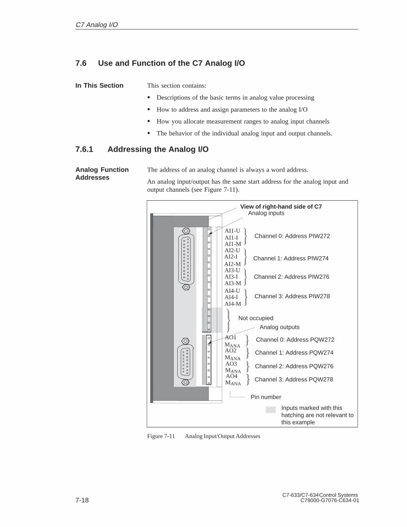
7-18C7-633/C7-634 Control Systems
C79000-G7076-C634-01
7.6 Use and Function of the C7 Analog I/O
This section contains:
Descriptions of the basic terms in analog value processing
How to address and assign parameters to the analog I/O
How you allocate measurement ranges to analog input channels
The behavior of the individual analog input and output channels.
7.6.1 Addressing the Analog I/O
The address of an analog channel is always a word address.
An analog input/output has the same start address for the analog input andoutput channels (see Figure 7-11).
AI1-UAI1-IAI1-MAI2-UAI2-IAI2-MAI3-UAI3-IAI3-MAI4-UAI4-IAI4-M
MANA
Not occupied
AO1
AO2
AO3
AO4
MANA
MANA
MANA
Channel 1: Address PQW274
Channel 2: Address PQW276
Channel 3: Address PQW278
Analog inputs
Pin number
Channel 0: Address PIW272
Channel 1: Address PIW274
Analog outputs
Channel 2: Address PIW276
Channel 3: Address PIW278
Channel 0: Address PQW272
Inputs marked with thishatching are not relevant tothis example
View of right-hand side of C7
Figure 7-11 Analog Input/Output Addresses
In This Section
Analog FunctionAddresses
C7 Analog I/O

7-19C7-633/C7-634 Control SystemsC79000-G7076-C634-01
7.6.2 Timing of the Analog I/Os
The timing of the analog inputs depends on the current parameter assignmentof the analog I/Os (see Section 7.6.3). The duration of the measuring cycledepends on the number of activated analog input channels. Deactivatedchannels reduce the length of the measuring cycle.The measuring cycle is the sum of the conversion times of the activatedanalog inputs.
A/D conversion of the channelsAI1 AI2 AI3 AI4 AI1
Measuring cycle
Processing timeof a channel
Processing timeof a channel
Processing timeof a channel
t
Figure 7-12 Measuring Cycle when All Analog Input Channels are Activated
A/D conversion of the channels
AI1 AI3 AI4 AI1 AI3
Measuring cycle
Processing timeof a channel
Processing timeof a channel
Processing timeof a channel
t
Figure 7-13 Measuring Cycle when Analog Input Channel 2 is Deactivated
Analog Inputs
C7 Analog I/O

7-20C7-633/C7-634 Control Systems
C79000-G7076-C634-01
The duration of the output cycle does not depend on the number of activatedanalog output channels. This is always constant and deactivated channels donot reduce the output cycle.
toutput cycle = 4 x t conversion time of a channel = const.
D/A conversion of the channelsAO1 AO2 AO3 AO4 AO1
Output cycle
Output timeof a channel
Output timeof a channel
Output timeof a channel
t
Figure 7-14 Output Cycle when All Analog Output Channels are Activated
D/A conversion of the channels
AO1AO2
AO3 AO4 AO1
Output cycle
Output timeof a channel
Output timeof a channel
Output timeof a channel
t
AO2
Deactivatedchannel
Figure 7-15 Output Cycle when Analog Output Channel 2 is Deactivated
Analog Outputs
C7 Analog I/O

7-21C7-633/C7-634 Control SystemsC79000-G7076-C634-01
7.6.3 Assigning Parameters to the Analog I/O
This chapter contains an overview of the analog I/O and their parameters.
You set the parameters for the analog I/O using the S7 applicationConfiguring Hardware. A parameter block is generated that contains all thecurrently selected I/O parameters. After loading this parameter block, theparameters are not immediately transferred to the analog I/O. The C7 CPUthen transfers the parameters to the analog I/O after every operating modechange from STOPRUN.
Alternatively, you can also change some parameters in the user program withSFCs 55 to 57 (see Reference Manual /235/).
We subdivide the parameters for the two configuration alternatives into:
Static parameters and
Dynamic parameters
The following table explains when the static and dynamic parameters areadopted.
Table 7-2 Time of Transfer of the Parameters from the C7 CPU to the Analog I/O
Parameter Set with Time of ParameterTransfer
Static Configuring Hardware STOP -> RUN
Dynamic Configuring Hardware STOP -> RUN
SFCs 55 to 57 RUN
The following parameter blocks permit the assignment of parameters inConfiguring Hardware to define the following characteristics of the analogI/O:
For inputs
– Basic settings
– Diagnostics
– Measurement
– Interrupt cycle
For outputs
– Basic settings
– Diagnostics
– Substitute values
– Output range
Overview
ParameterAssignment
Assignment ofParameters forCharacteristics
C7 Analog I/O
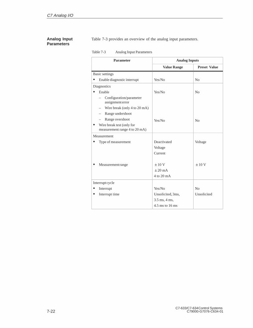
7-22C7-633/C7-634 Control Systems
C79000-G7076-C634-01
Table 7-3 provides an overview of the analog input parameters.
Table 7-3 Analog Input Parameters
Parameter Analog Inputs
Value Range Preset Value
Basic settings
Enable diagnostic interrupt Yes/No No
Diagnostics
Enable
– Configuration/parameterassignment error
– Wire break (only 4 to 20 mA)
– Range undershoot
– Range overshoot
Wire break test (only formeasurement range 4 to 20 mA)
Yes/No
Yes/No
No
No
Measurement
Type of measurement
Measurement range
Deactivated
Voltage
Current
10 V
20 mA
4 to 20 mA
Voltage
10 V
Interrupt cycle
Interrupt
Interrupt time
Yes/No
Unsolicited, 3ms,
3.5 ms, 4 ms,
4.5 ms to 16 ms
No
Unsolicited
Analog InputParameters
C7 Analog I/O

7-23C7-633/C7-634 Control SystemsC79000-G7076-C634-01
You can operate the inputs of the analog I/Os in three ways:
Without hardware interrupt
A free measuring cycle of all activated channels without generatinghardware interrupts.
A/D conversion of the channels
AI1 AI2 AI3 AI4
Measuring cycleof all activatedchannels
AI1 AI2 AI3 AI4
t
Figure 7-16 Sequence of the Measurement with Four Analog Input Channels withoutGenerating Hardware Interrupts
Hardware interrupt as a cyclic interrupt
Free measuring cycle of all activated channels with generation of a nonmeasuring cycle-dependent hardware interrupt as a time interrupt with aconfigurable interrupt time.
A/D conversion of the channels
AI1 AI2 AI3 AI4
Measuring cycleof all activatedchannels
AI1 AI2 AI3 AI4
t
AI1 AI2 AI3 AI4 AI1 AI2 AI3 AI4
Cycle time e.g. 3 ms Cycle time e.g. 3 ms
Hardware interruptto the C7 CPU
Hardware interruptto the C7 CPU
Hardware interruptto the C7 CPU
Figure 7-17 Sequence of the Measurement with Four Analog Input Channels andGeneration of Hardware Interrupts as Cyclic Interrupts
Hardware interrupt as cycle end interrupt
A measuring cycle with a configurable cycle time and generation of ahardware interrupt as a cycle end interrupt.
Hardware Interrupt
C7 Analog I/O

7-24C7-633/C7-634 Control Systems
C79000-G7076-C634-01
A/D conversion of the channels
AI4
Measuring cycleof all activatedchannels
AI1 AI2 AI3 AI4
t
AI1 AI2 AI3 AI4
Cycle time e.g. 4 ms
Hardware interruptto the C7 CPU
Hardware interruptto the C7 CPU
Hardware interruptto the C7 CPU
Cycle time e.g. 4 ms
A/D conversion of the channels
Figure 7-18 Sequence of the Measurement with Four Analog Input Channels withGeneration of Hardware Interrupts as Cycle End Interrupts
A hardware interrupt from the I/Os triggers the start of OB40 (hardwareinterrupt OB) on the C7 CPU. In this case, the process variableOB40_POINT_ADDR supplies the value DW#16#10000000.
Table 7-4 shows which parameters
Are static or dynamic
Can be set for all or individual analog inputs.
Table 7-4 Parameter Characteristics of Analog Inputs
Parameter Static/Dynamic Effective Range
Enable diagnostic interruptStatic Analog inputs/Analog outputs/Universal inputs
Enable diagnostics Static Channel
Wire break test Static Channel
Type of measurement Dynamic Channel
Measurement range Dynamic Channel
Interrupt cycle Dynamic Analog inputs
ParameterCharacteristics ofAnalog Inputs
C7 Analog I/O

7-25C7-633/C7-634 Control SystemsC79000-G7076-C634-01
Table 7-5 provides an overview of the analog output parameters.
Table 7-5 Analog Output Parameters
Parameter Analog Output
Value Range Preset Value
Basic setting
Enable diagnostic interrupt Yes/No No
Diagnostics
Enable
– Configuration/parameterassignment error
– Substitute value switched on
Yes/No No
Substitute value
Idle power and voltage (value 0)
Retain last value
Global substitute value
Yes/No
Yes/No
9400H...6C00H
Yes
No
0
Output range
Type of output
Output range
Deactivated
Voltage
Current
10 V
20 mA
4 to 20 mA
Voltage
10 V
Analog OutputParameters
C7 Analog I/O

7-26C7-633/C7-634 Control Systems
C79000-G7076-C634-01
Table 7-6 shows which parameters
Are static or dynamic
Can be set.
Table 7-6 Parameter Characteristics of Analog Outputs
Parameter Static/Dynamic Effective Range
Enable diagnostic interruptStatic Analog inputs /Analog outputs/Universal inputs
Enable diagnostics Static Outputs
Substitute value
Idle power and voltage(value 0)
Retain last value
Global substitute value
Dynamic
Dynamic
Dynamic
Outputs
Outputs
Outputs
Type of output Dynamic Outputs
Output range Dynamic Outputs
ParameterCharacteristics ofAnalog Outputs
C7 Analog I/O

7-27C7-633/C7-634 Control SystemsC79000-G7076-C634-01
7.6.4 Representation of Analog Values
The representation of analog values, or an analog value in binary form, is thesame for all C7 analog inputs and analog outputs.
This section describes the analog values for all measurement ranges or outputranges that can be used with the C7 analog I/O.
The digitalized analog value is the same for input and output values of thesame nominal range.
The representation of analog values is performed as a two’s complement
Table 7-7 illustrates the representation of the analog I/O:
Table 7-7 Representation of Analog Values
Resolution Analog Value
Bit number 15 14 13 12 11 10 9 8 7 6 5 4 3 2 1 0
Weighting of the bits S 214 213 212 211 210 29 28 27 26 25 24 23 22 21 20
The sign (S) of the analog value is always contained in bit number 15:
“0”
“1”
The resolution is 12 bit. The analog value is entered into the ACCU leftjustified. The unoccupied low significance places are written with “0” .
Table 7-8 contains an example of a bit pattern showing how theunoccupied places for 12-bit resolution are filled with “ 0” .
Table 7-8 Bit Pattern of a 12-Bit Analog Value (Example)
Resolution Analog Value
Bit number 15 14 13 12 11 10 9 8 7 6 5 4 3 2 1 0
12-bit analog value(incl. sign)
0 1 0 0 0 1 1 0 0 1 1 1 0 0 0 0
Overview
Representation ofAnalog Values
Sign Conventions
12-Bit Resolution
C7 Analog I/O

7-28C7-633/C7-634 Control Systems
C79000-G7076-C634-01
7.6.5 Representation of Analog Values for the Measurement Ranges ofthe Analog Inputs
The tables in this section contain the digitalized analog values for themeasurement ranges of the analog inputs.
In Table 7-9, you will find the representation of the binary analog values andthe associated decimal or hexadecimal representation of the units of theanalog values.
Table 7-10 contains the digitalized analog values for the variousmeasurement ranges.
Since the binary representation of the analog values is always the same, thistable contains only the comparison of the measurement ranges to the units.
This table is therefore clearer and easier to read. The corresponding binaryrepresentation of the measured values can be referred to in Table 7-9.
The bits identified with “x” are not relevant to a resolution of 12 bits.
Table 7-9 Possible Resolutions of Analog Values
Resolution in Bits Units Analog ValueResolut on n B ts(incl. Sign) Decimal Hexadecimal High Byte Low Byte
12 16 10H S 0 0 0 0 0 0 0 0 0 0 1 x x x x
Overview
How to Read theMeasured ValueTables
Measured ValueResolution
C7 Analog I/O

7-29C7-633/C7-634 Control SystemsC79000-G7076-C634-01
Table 7-10 contains the representation of the digitized voltage measurementranges for 10 V and the digitized current measurement ranges 20 mA,4 to 20 mA.
Table 7-10 Representation of the Digitalized Measured Value of the Analog Inputs (Voltage and CurrentMeasurement Ranges)
MeasuringRange
MeasuringRange
MeasuringRange
UnitsRangeRange
10 VRange 20 mA
Range4 to 20mA Decimal Hexadecimal
Range
11.759 23.516 0 32512 7F00H Overflow
11.7589 23.515 22.81 32511 7EFFH
: : : : : Upper range
10.0004 20.0007 20.005 27649 6C01H
pp g
10 20.000 20.000 27648 6C00H
7.500 14.998 : 20736 5100H
:0 :0 4.000 :0 :0H Nominal range
- 7.500 - 14.998 3.9995 -20736 AF00H
- 10 - 20.000 0 -27648 9400H
- 10.0004 - 20.0007 Underflowrange
-27649 93FFH
: : : : Lower range
- 11.759 - 23.516 -32512 8100H
- 11.76 - 23.517 -32513 80FFH Underflow
Voltage andCurrentMeasurementRanges
C7 Analog I/O
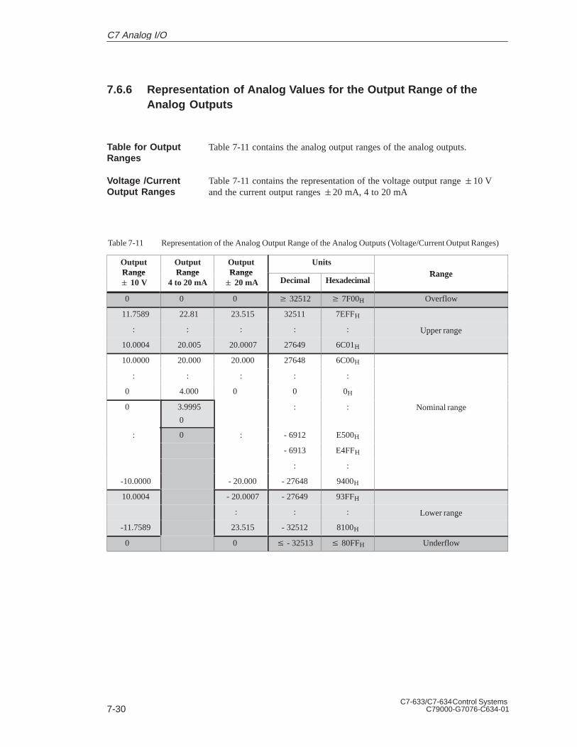
7-30C7-633/C7-634 Control Systems
C79000-G7076-C634-01
7.6.6 Representation of Analog Values for the Output Range of theAnalog Outputs
Table 7-11 contains the analog output ranges of the analog outputs.
Table 7-11 contains the representation of the voltage output range 10 Vand the current output ranges 20 mA, 4 to 20 mA
Table 7-11 Representation of the Analog Output Range of the Analog Outputs (Voltage/Current Output Ranges)
OutputRange
OutputRange
OutputRange
UnitsRangeRange
10 VRange
4 to 20 mARange 20 mA Decimal Hexadecimal
Range
0 0 0 32512 7F00H Overflow
11.7589 22.81 23.515 32511 7EFFH
: : : : : Upper range
10.0004 20.005 20.0007 27649 6C01H
pp g
10.0000 20.000 20.000 27648 6C00H
: : : : :
0 4.000 0 0 0H
0 3.9995
0
: : Nominal range
: 0 : - 6912 E500H
- 6913 E4FFH
: :
-10.0000 - 20.000 - 27648 9400H
10.0004 - 20.0007 - 27649 93FFH
: : : Lower range
-11.7589 23.515 - 32512 8100H
g
0 0 - 32513 80FFH Underflow
Table for OutputRanges
Voltage /CurrentOutput Ranges
C7 Analog I/O

7-31C7-633/C7-634 Control SystemsC79000-G7076-C634-01
7.6.7 Conversion and Cycle Time of the Analog Inputs
You can find the definitions and relationships between conversion time andcycle time for the analog inputs in this section.
The conversion time consists of the basic conversion time and an additionalconversion time necessary for the input calibration.
The analog-digital conversion and the transfer of the digitalized measuredvalues to the C7 CPU is performed sequentially, i.e. the analog inputchannels are converted one after the other. The cycle time, i.e. the elapsedtime before an analog input value is converted again, is the sum of allconversion times (0.5 ms/channel) of all activated analog input channels.Unused analog input channels should be deactivated in the ConfiguringHardware application in order to reduce the cycle time.
Figure 7-19 illustrates an overview of how the cycle time for a 4-channelanalog input is composed.
Conversion time channel 1
Conversion time channel 2
Conversion time channel 4
Cycle time (max. 2 ms)Conversion time channel 3
Figure 7-19 Cycle time of an Analog Input
If the interrupt cycle mode is assigned parameters, the new measuring cycleis not started unless the time interrupt is initiated (see Section 7.6.3).
Introduction
Conversion Time
Cycle Time
Interrupt Cycle
C7 Analog I/O
7-32C7-633/C7-634 Control Systems
C79000-G7076-C634-01
7.6.8 Conversion, Cycle, Settling and Response Times of Analog Outputs
This section contains the definitions and relationships between relevant timesfor the analog outputs.
The conversion time includes the acceptance of the digitalized output valuesfrom the internal memory and the digital-analog conversion.
The cycle time, i.e. the elapsed time before an analog output value is nextconverted is equal to the time for the conversion of the analog outputs.
The settling time (t2 to t3), that is the elapsed time between the creation ofthe converted value and the attainment of the specific value at the analogoutput, is load-dependent. You must differentiate between resistive,capacitive, and inductive load.
The response time, that is the interval between providing the digital outputvalue and attaining the specified value at the analog output, is between 100 µs and 2 ms.
Introduction
Conversion Time
Cycle Time
Settling Time
Response Time
C7 Analog I/O

7-33C7-633/C7-634 Control SystemsC79000-G7076-C634-01
7.6.9 Behavior of the Analog I/O
This section decribes:
The dependency of the analog input and output values on the supplyvoltages of the analog I/O and the operating modes of the C7.
The behavior of the analog I/O depending on the position of the analogvalues in the respective value range.
The influence of errors on the analog I/O.
The input and output values of the analog I/O are dependent upon the supplyvoltage of the analog I/O and the operating mode of the C7.
The triggering of a diagnostic interrupt is dependent upon the parameterassignment.
Table 7-12 gives an impression of these inter-relationships.
Table 7-12 Dependencies Between Analog Input and Output Values upon the Operating State of the C7 and uponthe Supply Voltage L+
Operating state of C7 Input value of the analog input Output value of the analog output
POWER ON RUN Process value C7 value
STOP Process value Substitute value or
Retain last value(configurable)
POWER OFF STOP – 0 signal
The behavior of the analog input is dependent upon the position of the inputvalues within the value range. Table 7-13 illustrates this dependency for theanalog input values.
Table 7-13 Behavior of the Analog Input Depending on the Position of the AnalogInput Value in the Value Range
Process Value lies in Input Value Diagnostics Interrupt
Nominal range Process value – –
Upper range/lowerrange
Process value – –
Overflow/underflow 7FFFH Message 1 Diagnostic interrupt1
1 According to parameter assignment
Overview
Influence of theSupply Voltageand the OperatingMode
Influence of theValue Range onthe Input
C7 Analog I/O

7-34C7-633/C7-634 Control Systems
C79000-G7076-C634-01
The behavior of the analog output is dependent upon the position of theoutput values within the value range. Table 7-14 illustrates this dependencyfor the analog output values.
Table 7-14 Behavior of the Analog Input in Relation to the Position of the AnalogInput Value in the Value Range
Output Value liesin
OutputValue
Diagnostics Interrupt
Nominal range C7 value – –
Upper range/lowerrange
C7 value – –
Overflow/underflow 0 signal – –
Errors lead to a diagnostic message and diagnostic interrupt if diagnosticparameters have been assigned (see Section 10.2).
Influence of theValue Range forthe Output
Influence of Errors
C7 Analog I/O

7-35C7-633/C7-634 Control SystemsC79000-G7076-C634-01
7.6.10 Time Interrupt/Interrupt Cycle
If the interrupt cycle mode is assigned parameters, the new measuring cycleis not started unless the time interrupt is initiated (see Section 7.6.3).
Use the STEP 7 application Configuring Hardware for parameter assignment.
If a hardware interrupt is transferred from the I/O to the C7 CPU, thehardware interrupt OB (OB40) is called in the C7 CPU. The event whichcalled OB40 is stored in the start information (declaration section) of OB40.You have to evaluate the additional information Z1 to Z3 in the startinformation.
The entries in the declaration section of OB40 are listed in Table 7-15. Thebytes relevant to the user are hatched in the table.
Table 7-15 Declaration Section of OB40
Byte Meaning Meaning Byte
0 Class Identifier Event number 1
2 Priority class Current OB number 3
4 Data identifiers Z2/3 Data identifier Z1 5
6 Additional information Z1 7
8 Additional information Z2 9
10 Additional information Z3 11
12 Time stamp of event 13
14 15
16 17
18 19
Additional information Z1 contains the start address of the C7 I/O module(bytes 6/7).
Address: 272 or 0110H
Bit 4 of byte 8 = 1 in the case of an end-of-cycle interrupt.
Additional information Z3 is not used and assigned the value 0000H.
The evaluation of hardware interrupts in the user program is described in themanual /234/.
Interrupt Cycle
ConfigurableEvents
Hardware InterruptOB
DeclarationSection of OB40
AdditionalInformation Z1
AdditionalInformation Z2
AdditionalInformation Z3
Evaluation in theUser Program
C7 Analog I/O

7-36C7-633/C7-634 Control Systems
C79000-G7076-C634-01
7.7 Examples for Programming the Analog I/O
The following examples for programming the analog I/O will help tofamiliarize you with the principles of programming the C7 I/O.
7.7.1 Block for Scaling Analog Input Values
The FC126 block is used to convert the actual value entered as ahexadecimal number in a peripheral input word into a corresponding-pointnumber (=analog value) to be output to a memory double word. For thispurpose, a simple calculation using the rule of three is programmed.
1. First, the actual value is related to the total range (RANGE_HEX)resulting from the difference (UL - LL).
The result is a percentage of the absolute actual value. This is identical inthe floating-point number and in the hexadecimal representation.
2. Then the total range resulting from the difference (UL - LL) is calculatedin floating-point number representation, depending on whether themeasuring range is unipolar or bipolar.
3. Now the percentage (PERCENT) calculated before is related to the totalfloating-point number range.
The result is the absolute read-in value.
4. Finally, the lower limit (LL) is added to this value as the offset.
5. The resulting floating-point number is output.
PERCENT=(channel - LL) / (UL - LL)RANGE_HEX=UL - LLactual value=PERCENT*(upper limit - lower limit) + lower limit
Overview
Function of Block
Summary ofFormulae
C7 Analog I/O

7-37C7-633/C7-634 Control SystemsC79000-G7076-C634-01
The FC126 function contains the following statement lines:
FUNCTION FC 126: void
var_inputlower limit: DWORD;upper limit: DWORD;channel: DWORD;
end_var
var_outputactual value : DWORD;
end_var
var_tempLL:DWORD;RANGE_HEX:DWORD;PERCENT:DWORD;
end_var
BEGIN
//***Case: unipolar or bipolar measuring range?***L lower limit; // lower limit negative?L 0.0; // yes=> bipolar measuring range<R;JC bipo;
L DW#16#000_00000; // unipolar range lower limitT LLJU comp;
bipo: NOP 0;L W#16#9400; // bipolar range lower limitITD;T LL;
//***Computing the range (hexadecimal)***comp:NOP 0;
L W#16#6C00; // upper limit for unipolar and bipolar//range identical
ITD;L LL;-D;T RANGE_HEX; // buffer difference
FC126 Sequenceof Statements
C7 Analog I/O
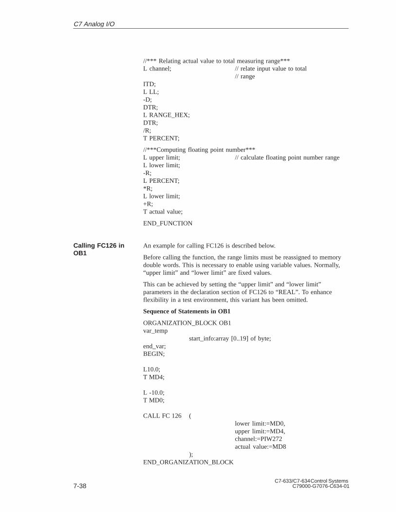
7-38C7-633/C7-634 Control Systems
C79000-G7076-C634-01
//*** Relating actual value to total measuring range***L channel; // relate input value to total
// rangeITD;L LL;-D;DTR;L RANGE_HEX;DTR;/R;T PERCENT;
//***Computing floating point number***L upper limit; // calculate floating point number rangeL lower limit;-R;L PERCENT;*R;L lower limit;+R;T actual value;
END_FUNCTION
An example for calling FC126 is described below.
Before calling the function, the range limits must be reassigned to memorydouble words. This is necessary to enable using variable values. Normally,“upper limit” and “lower limit” are fixed values.
This can be achieved by setting the “upper limit” and “lower limit”parameters in the declaration section of FC126 to “REAL”. To enhanceflexibility in a test environment, this variant has been omitted.
Sequence of Statements in OB1
ORGANIZATION_BLOCK OB1var_temp
start_info:array [0..19] of byte;end_var;BEGIN;
L10.0;T MD4;
L -10.0;T MD0;
CALL FC 126 (lower limit:=MD0,upper limit:=MD4,channel:=PIW272actual value:=MD8
);END_ORGANIZATION_BLOCK
Calling FC126 inOB1
C7 Analog I/O

7-39C7-633/C7-634 Control SystemsC79000-G7076-C634-01
7.7.2 Block for Scaling Analog Output Values
The FC127 block is used to convert the setpoint to be specified in a memorydouble word as a floating-point number to the corresponding hexadecimalpattern (=analog value) which must be output to a peripheral output word.For this purpose, a simple calculation using the rule of three is programmed.
1. First, the setpoint is related to the total range (RANGE_DEC) resultingfrom the difference (upper limit - lower limit).
The result is a percentage of the absolute setpoint value. This is identicalin the floating-point number and in the hexadecimal representation.
2. Then the total range (RANGE_HEX), resulting from the difference (UL -LL) is calculated in hexadecimal representation, depending on whetherthe measuring range is unipolar or bipolar.
3. Now the percentage (PERCENT) calculated before is related to the totalhexadecimal range (RANGE_HEX).
The result is the absolute value to be output.
4. Finally, the lower limit (LL) is added to this value as the offset.
5. The resulting bit pattern is output.
PERCENT = (setpoint - lower limit) / (upper limit - lower limit)RANGE_DEC = upper limit - lower limitRANGE_HEX = UL - LLChannel = PERCENT * RANGE_HEX + LL
The FC127 function contains the following statement lines:
FUNCTION FC 127: void
var_inputlower limit: DWORD;upper limit: DWORD;setpoint: DWORD;
end_var
var_tempLL : DWORD;UL : DWORD;RANGE_DEC : DWORD;RANGE_HEX : DWORD;PERCENT : DWORD;
end_var
Function of Block
Summary ofFormulae
FC127 Sequenceof Statements
C7 Analog I/O

7-40C7-633/C7-634 Control Systems
C79000-G7076-C634-01
BEGIN
//***Case: unipolar or bipolar measuring range?***L lower limit; // lower limit negative?L 0.0; // yes => bipolar measuring range<R;JC bipo;
L DW#16#0000_0000; //unipolar range lower limitT LLJU comp;
bipo NOP 0L W#16#9400; // bipolar range lower limitITD;T LL;
//***Calculating the range (hexadecimal)***comp: NOP 0;
L W#16#6C00; // upper limit for unipolar and bipolar// range identical
ITD;L LL;-D;T RANGE_HEX; // buffer difference
//*** Relating setpoint to total measuring range***L upper limit; // compute rangeL lower limit-R;T RANGE_DEC;
L setpoint; // relate setpoint to total// range
L lower limit;-R;L RANGE_DEC;/R;T PERCENT;
//***Computing hex pattern to be output***L RANGE_HEX; // relate hex value to total rangeDTR;L PERCENT;*R;L LL; // add offsetDTR;+R;RND; // convert floating-point number to
// 32-bit integerT channel; // output result
C7 Analog I/O

7-41C7-633/C7-634 Control SystemsC79000-G7076-C634-01
An example for calling FC127 is described below.
Before calling the function, the range limits and the setpoint must bereassigned to memory double words. This is necessary to enable usingvariable values. Normally, “upper limit” and “lower limit” are fixed values;the “setpoint” is variable.
This can be achieved by setting the “upper limit” and “lower limit”parameters in the declaration section of FC127 to “REAL”. To enhanceflexibility in a test environment, this variant has been omitted.
Sequence of Statements in OB1
ORGANIZATION_BLOCK OB1var_temp
start_info:array [0..19] of byte;end_varBEGIN
L -10.0;T MD0;
L 10.0;T MD4;
L 2.2;T MD8;
CALL FC 127 (lower limit:=MD0,upper limit:=MD4,setpoint:=MD8,channel:=PQW272
);
END_ORGANIZATION_BLOCK
Calling FC127 inOB1
C7 Analog I/O

7-42C7-633/C7-634 Control Systems
C79000-G7076-C634-01
C7 Analog I/O

8-1C7-633/C7-634 Control SystemsC79000-G7076-C634-01
C7 Universal Inputs
Section Description Page
8.1 Universal Inputs 8-2
8.2 Use and Function of the Universal Inputs 8-6
8.2.1 Addressing Universal Inputs 8-6
8.2.2 Assigning Parameters to the Universal Inputs 8-9
8.2.3 Interrupt Inputs and Counter Interrupts 8-12
8.2.4 Counters 8-14
8.2.5 Frequency Counters 8-17
8.2.6 Period Time Measurement 8-19
8.2.7 External Gate Counter 8-22
8.3 Example for Programming the Counters 8-23
Chapter Overview
8

8-2C7-633/C7-634 Control Systems
C79000-G7076-C634-01
8.1 Universal Inputs
The C7 has 4 digital universal inputs that provide the following functionality:
Interrupt input
Counter input
Frequency/period duration counter input
Digital input
External gate counter input
These input functions can be set by assigning them parameters; thisdetermines how the inputs are used.
Overview
C7 Universal Inputs

8-3C7-633/C7-634 Control SystemsC79000-G7076-C634-01
Figure 8-1 shows the pin assignments of the universal inputs
Pin No.
0.00.10.20.30.4
0.50.60.71.01.11.21.31.4
1.51.61.7
Address 287.3
GATE 3
Address 287.2
GATE 2
Address 287.1
GATE 1
Address 287.0M
DI-X1DI-X2DI-X3DI-X4
Universal inputs
Parts shaded in this wayare not relevant for theexplanation.
View of right-hand side of C7
DI to control ext. gate counter 1DI to control ext. gate counter 2DI to control ext. gate counter 3
Figure 8-1 Pin Assignments of the Universal Inputs
TerminalConnectionDiagram
C7 Universal Inputs

8-4C7-633/C7-634 Control Systems
C79000-G7076-C634-01
The pin assignments of the universal inputs are as follows:
Table 8-1 Assignments of the Universal Inputs
Pin No. Function
M Associated ground
DI-X1 Universal input 1 (interrupt, digital and counter input, external gate counter16 bit)
DI-X2 Universal input 2 (interrupt, digital and counter input, external gate counter16 bit)
DI-X3 Universal input 3 (interrupt, digital, counter, frequency counter and period duration counter input, external gate counter 24 bit)
DI-X4 Universal input 4 (interrupt or digital input)
GATE 1 External gate pin for DI-X1
GATE 2 External gate pin for DI-X2
GATE 3 External gate pin for DI-X3
The universal inputs are set using software. This is done using theConfiguring Hardware application. You use this application to determinewhich function the individual input is to execute (see Table 8-1).
If this function is set, the input responds like a normal interrupt input, that is,a hardware interrupt is triggered in the C7 CPU as a response to the assignededge.
If this function is set, the input responds like a normal digital input (seeSection 6.1). The only difference here is that the current process signal is notautomatically given to the control program but must first be read in from theI/O.
These universal inputs enable you to capture counter pulses up to a frequencyof 10 kHz. The counter can count either up or down. You can also assignparameters to the count edge.
This enables you to count pulses within a programmed length of time. Fromthis you can calculate a frequency 10 kHz.
This function enables you to count fixed timer ticks between two positiveedges. From this you can calculate the duration of an interval period.
This function enables you to count pulses within a gate time that starts with arising edge on the external gate pin and ends with a falling edge.
Pin Assignmentsof the UniversalInputs
AssigningParameters to theInputs
Interrupt Input
Digital Input
Counter Input
FrequencyCounter
Period DurationCounter
External Gate Counter
C7 Universal Inputs

8-5C7-633/C7-634 Control SystemsC79000-G7076-C634-01
Specific Data of the Universal Inputs
Number of inputs 4 + 3 (gate pins)
Cable length, shielded 1000 m
unshielded 600 m
Voltages, Currents, Potentials
Nominal load voltage L + 24 VDC
Number of simultaneouslyenergizable inputs
4 + 3 (gate pins)
Galvanic isolation No
Function, Interrupts, Diagnostics
InterruptsCounter functionsMax. counter frequencyDiagnostic function
Counters Principle Counter range C1/C2
Counter range C3
Limit value (setpoint)specification
Counter interrupt of upcounter
Counter interrupt of downcounter
Enable
Period Duration Counter Principle
Counter range Max. period duration
Frequency Counter Principle
Counter range Gate width Max. frequency
Can be assignedparameters10 kHzModule standarddiagnostics inconjunction withanalog I/O.No channel-specificdiagnosticsMax. 3Edge countingup 0 to 216-1down 216-1 to 0up 0 to 224-1down 224-1 to 01 value per counter
When limit value isreached
When “0” is reached
In the program
Max. 1Counting fixed timeunits between twopositive edges0 to 224-18.395 s or 0.119 Hz
Max. 1Counting of pulseswithin a time period0 to 224-10, 1 s, 10 s (can be set)10 kHz; limited byinput filter
External Gate Counter Principle
Counter range C1/C2
Counter range C3
Max. 3Edge counting viaexternal pin0 to 216-1
0 to 224-1
Data for Selecting a Sensor
Input voltage
Nominal voltage
For “1” signal
For “0” signal
24 VDC
from 11 to 30 V
from -3 to 5 V
Input current
At “1” signal from 2 to 8 mA
Input delay time
Configurable
From “0” to “1”
From “1” to “0”
No
approx. 0.01 ms
approx. 0.01 ms
Input characteristic In accordance withIEC 1131, Part 2
Type of input in accordancewith IEC 1131
Type 2
Input current
At “1” signal From 6 to 11.5 mA
TechnicalSpecifications ofthe UniversalInputs
C7 Universal Inputs

8-6C7-633/C7-634 Control Systems
C79000-G7076-C634-01
8.2 Use and Function of the Universal Inputs
In this section you can find:
Basic terminology about the function of the universal inputs
How you can use the universal inputs
How you can address and assign parameters to the universal inputs
8.2.1 Addressing Universal Inputs
You can select the following functions by assigning the appropriateparameters to the universal inputs:
Digital input
Interrupt input
Counter
Frequency counter
Period time counter
External gate counter
The addresses for the universal inputs are default addresses which cannot bechanged. According to the application of the universal inputs, the resultsoccupy differing addresses.
For the address allocation, a distinction is made between:
The input range PIW280 to PIB287 for count values or signal state of thedigital inputs, and
The output/control range PQW 280 to PQB287 for counters
In This Section
Overview
Universal InputAddresses
C7 Universal Inputs

8-7C7-633/C7-634 Control SystemsC79000-G7076-C634-01
The 4 universal inputs of the input range (see Figure 8-1) have the followingaddresses and weightings:
Table 8-2 Input Address of the Universal Inputs
Address Designation
PIB280PIB281
CI1: Counter input
PIB282PIB283
CI2: Counter input
PIB284
PIB285
PIB286
CI3: Counter input
Frequency/periodtime counter
PIB287 Bit 7 ––
Bit 6
Bit 5 States of the count inputs see Table 8-3
Bit 4
Bit 3 Current state of universal input 4
Bit 2 Current state of universal input 3
Bit 1 Current state of universal input 2
Bit 0 Current state of universal input 1
The state of the individual inputs is stored as a bit pattern in PIB287:
Table 8-3 State of the Inputs
AddressPIB287
Status Display of Universal Inputs
Bit7 ––
Bit 6*) Bit = 1: Counter 3 enabledBit = 0: Counter 3 disabled
Bit 5*) Bit = 1: Counter 2 enabledBit = 0: Counter 2 disabled
Bit 4*) Bit = 1: Counter 1 enabledBit = 0: Counter 1 disabled
Bit 3
Bit 2
Bit 1
Bit 0
Bit = 1: universal input 1 set. Bit = 0: universal input 1 reset.
Bit = 1: universal input 2 set. Bit = 0: universal input 2 reset
Bit = 1: universal input 3 set. Bit = 0: universal input 3 reset.
Bit = 1: universal input 4 set. Bit = 0: universal input 4 reset.
*) Only relevant if universal input was assigned as count input
Input Range
States of theInputs
C7 Universal Inputs

8-8C7-633/C7-634 Control Systems
C79000-G7076-C634-01
If the universal inputs are used as counters, then the behavior of the countersis controlled via the output range.
Table 8-4 Addresses and Weighting of the Output Range of the Count Inputs
Address Control of Counters 1 to 3
PQW280 Start/comparison value counter 1*
PQB287: Bit 0
Bit 1
0 = Counter 1 disabled 1 = Counter 1 enabled
0 = Do not accept new start/comparison value
1 = Set new start/comparison value
PQW282 Start/comparison value counter 2*
PQB287: Bit 0
Bit 1
0 = Counter 2 disabled 1 = Counter 2 enabled
0 = Do not accept new start/comparison value
1 = Set new start/comparison value
PQB284
PQB285
PQB285
Start/comparison value counter 3 *
PQB287 Bit 4
Bit 5
0 = Counter 3 disabled 1 = Counter 3 enabled
0 = Do not accept new start/comparison value
1 = Set new start/comparison value
*) Initial value for down counter, comparison value for up counter
Note
Please note that no direct read-in function is available for reading in thecomplete counter status of counter 3.
When counting in the 0 to 65535 value range (2 bytes), the counter valuesare stored in PQW285.
Output Range
C7 Universal Inputs

8-9C7-633/C7-634 Control SystemsC79000-G7076-C634-01
8.2.2 Assigning Parameters to the Universal Inputs
In the parameter block “universal inputs” you set the parameters for:
The interrupt inputs
The counters
The frequency meter/period time counter
The digital inputs
The external gate counter
You set the parameters for the universal inputs using the STEP 7 applicationConfiguring Hardware. A parameter block is generated which contains allcurrently selected parameters of the universal inputs. After loading thisparameter block, the C7 CPU then transfers the parameters to the appropriateuniversal inputs at every operating mode change from STOP RUN.
If the universal inputs are used as interrupt inputs, a hardware interrupt willbe triggered on the C7 CPU for the assigned rising or falling edge at theinput. The default is the rising edge.
The universal inputs 1 to 3 can be assigned as:
Counter input, 16 bit (counters 1 and 2)
Counter input, 24 bit (counter 3)
Frequency counter (input 3 only)
Period time counter (input 3 only)
External gate counter, 16 bit (inputs 1 and 2 only)
External gate counter, 24 bit (input 3 only)
The counter values are made available to the user program as 16-bit or 24-bitvalues and the frequency and period time counter values as 24-bit values.The counter values of the external gate counter are either 16-bit or 24-bitvalues, depending on the input.
Parameter BlockUniversal Inputs
AssigningParameters
Interrupt Inputs
Counter Inputs
C7 Universal Inputs

8-10C7-633/C7-634 Control Systems
C79000-G7076-C634-01
Table 8-5 lists the parameters for the above-mentioned functions:
Table 8-5 Parameter Block of the Count Inputs
Parameter Explanation Value Range Default Setting
Count input 1 Activate the count input and define the type ofcounting
StandardInterruptCounter
HW gate counter
Standard
Define the count direction UpDown
Up
Set edge to be used for counting Rising edgeFalling edge
Rising edge
Counter can trigger a hardware interrupt afterreaching the comparison value (when counting up)or on zero transition (when counting down)
YesNo
No
No further parameters for external gate counter(16 bit)
– –
Count input 2 Activate the count input and define the type ofcounting
StandardInterruptCounter
HW gate counter
Standard
Define the count direction UpDown
Up
Set edge to be used for counting Rising edgeFalling edge
Rising edge
Counter can trigger a hardware interrupt afterreaching the comparison value (when counting up)or on zero transition (when counting down)
YesNo
No
No further parameters for external gate counter(16 bit)
– –
C7 Universal Inputs

8-11C7-633/C7-634 Control SystemsC79000-G7076-C634-01
Table 8-5 Parameter Block of the Count Inputs
Parameter Default SettingValue RangeExplanation
Count input 3 Activate the count input and define the type ofcounting
StandardInterruptCounter
Frequency counterPeriod duration
counterHW gate counter
Standard
If counter activated then define the count direction UpDown
Up
If counter activated then define the edge to be usedfor counting
Rising edgeFalling edge
Rising edge
If counter activated, then the counter can trigger ahardware interrupt after reaching the comparisonvalue (when counting up) or on zero transition(when counting down)
YesNo
No
If frequency counter selected, then select the gatetime for the frequency counting
0.1 s1 s10 s
1 s
No further parameters for period time counter – –
No further parameters for external gate counter(24 bit)
– –
If the universal inputs are deactivated in the parameter block (defaultsetting), then the inputs react as digital inputs. However, no automaticallyupdated process image will be made available to the user program for theseinputs. The current state of the input can only be read by means of a directI/O access. (See Table 8-2 or 8-3 for address).
Digital Inputs
C7 Universal Inputs

8-12C7-633/C7-634 Control Systems
C79000-G7076-C634-01
8.2.3 Interrupt Inputs and Counter Interrupts
If universal inputs are used as interrupt inputs, then a hardware interrupt willbe generated every time there is a corresponding (assigned) edge at one ofthe inputs.
The universal input counters can be assigned parameters for hardwareinterrupts. In this case, a forward counter triggers a hardware interrupt whenit reaches the comparison value, and a backward counter when it passesthrough zero.
The parameter assignment can be performed with STEP 7 applicationConfiguring Hardware or with one of the system functions SFC55 to SFC58.
If a hardware interrupt is sent from the I/O to the C7 CPU, then the hardwareinterrupt OB (OB40) will be called on the C7 CPU. The event that called theOB40 is stored in the start information (declaration section) of the OB40.You must evaluate the additional information Z1 to Z3 in the startinformation.
The entries in the declaration section of OB40 can be found in Table 8-6. Thebytes that are relevant to the user are hatched in the table.
Table 8-6 Declaration section of OB40
Byte Meaning Meaning Byte
0 Class Identifier Event number 1
2 Priority class Current OB number 3
4 Data identifier Z2/3 Data identifier Z1 5
6 Additional information Z1 7
8 Additional information Z2 9
10 Additional information Z3 11
12 Time stamp of event 13
14 15
16 17
18 19
The start address of the C7 I/O module is contained in the additionalinformation Z1 (byte 6/7). Address: 272 or 0110H
Introduction to Interrupt Inputs
Introduction to Counter Interrupts
Assignable Events
Hardware InterruptOB
DeclarationSection of OB40
AdditionalInformation Z1
C7 Universal Inputs

8-13C7-633/C7-634 Control SystemsC79000-G7076-C634-01
The consecutive number of the universal input that triggered the hardwareinterrupt can be found in byte 8 of the additional information Z2. Byte 9 isirrelevant.
You can find the additional information broken down into bits in Figure 8-2.
01 1
06 5 4 3 2 1 0
Byte 8
1, when universal input 1has triggered hardware interrupt
7
0 0 0 0
1, when universal input 2has triggered hardware interrupt
1, when universal input 3has triggered hardware interrupt
1, when universal input 4has triggered hardware interrupt
01
01
Figure 8-2 Additional Information Z2
The consecutive number of the universal input that triggered the hardwareinterrupt can be found in byte 8 of the additional information Z2. Byte 9 isirrelevant.
You can find the additional information broken down into bits in Figure 8-3.
06 5 4 3 2 1 0
Byte 8
1, when counter input 1has triggered hardware interrupt
7
0 0 0 0
1, when counter input 2has triggered hardware interrupt
1, when counter input 3has triggered hardware interrupt
101
01
01
Figure 8-3 Structure of Additional Information Z3 in Declaration Section of OB40
Additional information Z3 is not used and is set to 0000H.
The evaluation of hardware interrupts in the user program is described in themanual /280/.
AdditionalInformation Z2 forInterrupt Inputs
AdditionalInformation Z2 forCounter Interrupts
AdditionalInformation Z3
Evaluation in theUser Program
C7 Universal Inputs

8-14C7-633/C7-634 Control Systems
C79000-G7076-C634-01
8.2.4 Counters
The counter calculates the actual value of the count from the count pulses (upor down).
You can assign parameters with the STEP 7 application ConfiguringHardware or with the system functions SFC55 to SFC58 to define whether:
A count pulse is triggered by a rising or falling edge at the correspondinguniversal input
Counting is up or down
A hardware interrupt is to be triggered or not.
The counter calculates the actual value according to the following formula:
Actual value (counter up) = number of edges
or
Actual value (counter down) = start value minusnumber of edges
Counting up starts at zero or is continued from the last counter value until theselected comparison value is reached or to the end of the count range (defaultsetting). The start value after resetting the counter is always zero. Thecomparison value is set by the user program.
Counting down starts counting backwards from the selected start value or iscontinued from the last counter value until the value zero is reached. Thestart value is set by the user program.
The universal input counter counts count pulses up to a maximum frequencyof 10 kHz.
A frequency filter is fitted to the inputs.
!Warning
If the actual frequency exceeds the threshold frequency of 10 kHz, then thecorrect function of the universal inputs can no longer be guaranteed, sincecount pulses will be lost.
Before activating a counter in OB100, it is necessary to insert a delay timeof at least 5 ms via SFC47.
Counter
Actual Value ofCounter
Counting Up
Counting Down
Exceeding theThresholdFrequency
C7 Universal Inputs

8-15C7-633/C7-634 Control SystemsC79000-G7076-C634-01
Note
The counting process on the C7 I/O module is asynchronous to the C7 CPUuser program. The user program is cyclically supplied with the current countvalue (update time 0.5 ms). This means that when reading in the currentprocess value via the user program (for example, L PIW280), this value is upto 500 µs older. With high counting frequencies there can be an offset ofseveral count pulses (for example, 10 kHz = 1 pulse every 100 µs; that is, thecounter has already counted up to 4 more pulses).
Depending on the application, it is necessary to take this into account (forexample, waiting time of > 0.5 ms after the counting encoder has stopped; orusing a hardware interrupt until counter end value).
The universal counter inputs are controlled by the user program.
Table 8-7 lists the different ways of influencing the counter in the userprogram. For a detailed description of the individual bits in PQB287, pleaserefer to Table 8-4.
Table 8-7 Controlling Counters with the User Program
Aim Procedure
Start counter Enter a valid start value (if counting down) ora valid comparison value (if counting up) (PQW280, PQW282, PQB284, PQB 285, PQB 286)
Activate the new start/comparison value(PQB287 rising edge ‘0’‘1’)
Start the counter by selecting the start bit(PQB287 falling edge ‘1’‘0’
Stop counter Reset the start bit(PQB287 falling edge ‘1’‘0’)
Restart counter with counterinitialization (reset)
If necessary, enter a new start value or retain oldstart value (for counting down) or comparison value (for counting up) (PQW280,PQW282, PQB284, PQB285, PQB286)
Activate the new start/comparison value (PQB287 rising edge ‘0’‘1’)
Set the start bit (PQB287 rising edge ‘0’‘1’)
Restart counter withoutcounter initialization(counter continues countingwithout a reset)
Do not set the new start/comparison value
Start the counter by setting the start bit(PQB287 rising edge ‘0’‘1’)
Starting andStopping Counters
C7 Universal Inputs

8-16C7-633/C7-634 Control Systems
C79000-G7076-C634-01
Table 8-7 Controlling Counters with the User Program
Aim Procedure
Select new start/comparisonvalue
Enter new start/comparison value(PQW280, PQW282, PQB284, PQB285, PQB286)
Set value(PQB287 rising edge ‘0’‘1’
– New start/comparison value will beactivated with the next rising edge at the count input
– If counting up is running: new comparison value will be accepted
– If counting down is running: new start value will be accepted, current count value will be corrected by the difference
Initialize counter (start of anew counting process)always occurs:
At zero transition (counting down) or comparison value reached/exceeded (counting up)
After setting the enable bit in the data area(PQB287 rising edge ‘0’‘1’),if the bit “set new start/comparison value” is set simultaneously (PQB287)
Generate hardware interruptand reset counter
Requirement is that the option “hardwareinterrupt = yes” has been assigned for the counter
When counting direction is forwards, if countvalue = comparison value
When counting direction is backwards, if countvalue = zero
C7 Universal Inputs
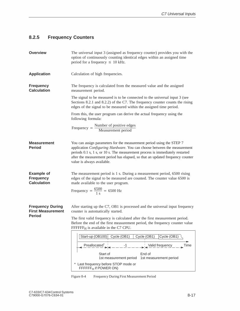
8-17C7-633/C7-634 Control SystemsC79000-G7076-C634-01
8.2.5 Frequency Counters
The universal input 3 (assigned as frequency counter) provides you with theoption of continuously counting identical edges within an assigned timeperiod for a frequency 10 kHz.
Calculation of high frequencies.
The frequency is calculated from the measured value and the assignedmeasurement period.
The signal to be measured is to be connected to the universal input 3 (seeSections 8.2.1 and 8.2.2) of the C7. The frequency counter counts the risingedges of the signal to be measured within the assigned time period.
From this, the user program can derive the actual frequency using thefollowing formula:
FrequencyNumber of positive edges
Measurement period
You can assign parameters for the measurement period using the STEP 7application Configuring Hardware. You can choose between the measurementperiods 0.1 s, 1 s, or 10 s. The measurement process is immediately restartedafter the measurement period has elapsed, so that an updated frequency countervalue is always available.
The measurement period is 1 s. During a measurement period, 6500 risingedges of the signal to be measured are counted. The counter value 6500 ismade available to the user program.
Frequency 65001 s 6500 Hz
After starting up the C7, OB1 is processed and the universal input frequencycounter is automatically started.
The first valid frequency is calculated after the first measurement period.Before the end of the first measurement period, the frequency counter valueFFFFFFH is available in the C7 CPU.
Start-up (OB100) Cycle (OB1) Cycle (OB1) Cycle (OB1)
-1 Valid frequency Time
Start of1st measurement period
Preallocated*
* Last frequency before STOP mode or FFFFFFH if POWER ON)
End of1st measurement period
Figure 8-4 Frequency During First Measurement Period
Overview
Application
FrequencyCalculation
MeasurementPeriod
Example ofFrequencyCalculation
Frequency DuringFirst MeasurementPeriod
C7 Universal Inputs
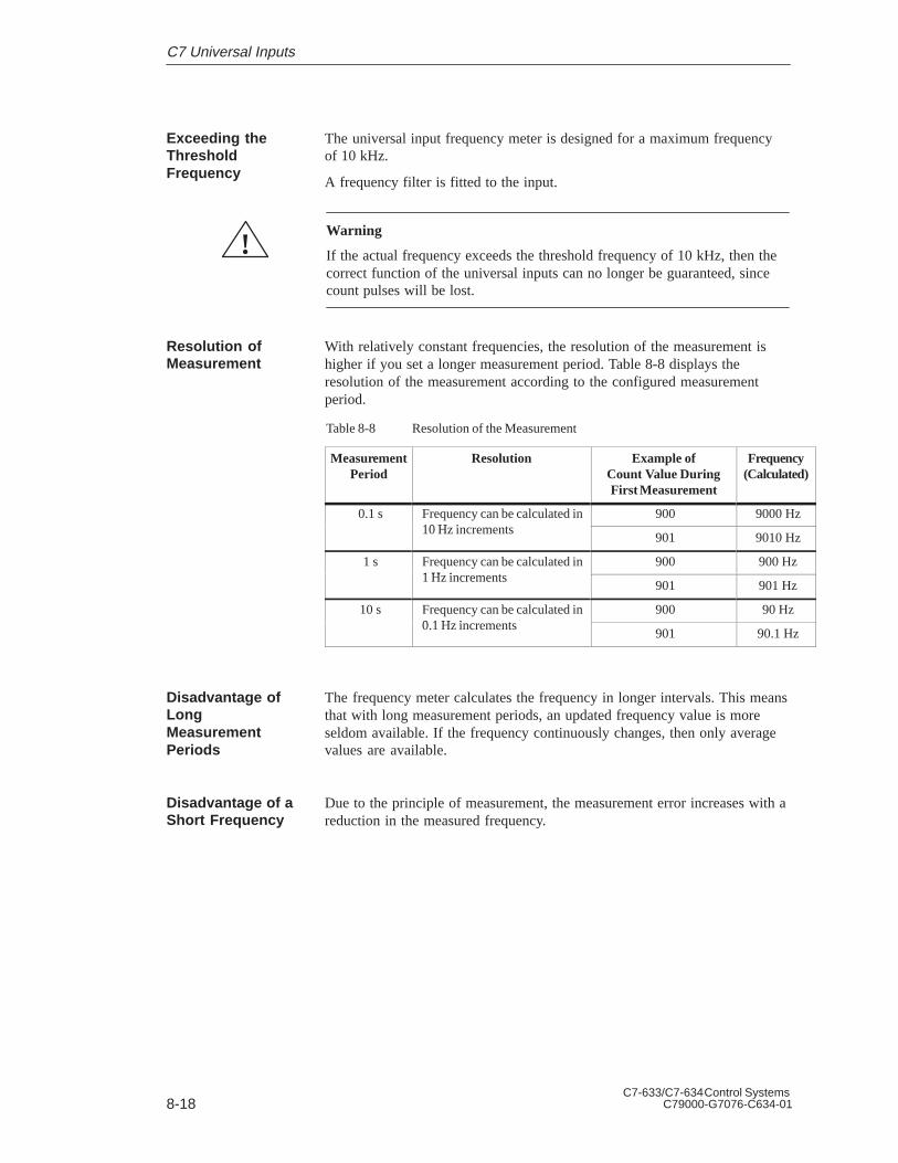
8-18C7-633/C7-634 Control Systems
C79000-G7076-C634-01
The universal input frequency meter is designed for a maximum frequency of 10 kHz.
A frequency filter is fitted to the input.
!Warning
If the actual frequency exceeds the threshold frequency of 10 kHz, then thecorrect function of the universal inputs can no longer be guaranteed, sincecount pulses will be lost.
With relatively constant frequencies, the resolution of the measurement ishigher if you set a longer measurement period. Table 8-8 displays theresolution of the measurement according to the configured measurementperiod.
Table 8-8 Resolution of the Measurement
MeasurementPeriod
Resolution Example ofCount Value DuringFirst Measurement
Frequency(Calculated)
0.1 s Frequency can be calculated in10 H i t
900 9000 Hz10 Hz increments
901 9010 Hz
1 s Frequency can be calculated in1 H i t
900 900 Hz1 Hz increments
901 901 Hz
10 s Frequency can be calculated in0 1 H i t
900 90 Hz0.1 Hz increments
901 90.1 Hz
The frequency meter calculates the frequency in longer intervals. This meansthat with long measurement periods, an updated frequency value is moreseldom available. If the frequency continuously changes, then only averagevalues are available.
Due to the principle of measurement, the measurement error increases with areduction in the measured frequency.
Exceeding theThresholdFrequency
Resolution ofMeasurement
Disadvantage ofLongMeasurementPeriods
Disadvantage of aShort Frequency
C7 Universal Inputs
8-19C7-633/C7-634 Control SystemsC79000-G7076-C634-01
8.2.6 Period Time Measurement
The universal input 3 can be assigned as period time counter. This universalinput reads pulses from a transducer. The transducer could, for example, befitted to the barrel extruder of an injection moulding machine.
Calculation of low frequencies and rotation speeds.
The period time counter counts the number of increments (fixed timeintervals) of tzi = 0.5 s between two rising edges. The first period starts atthe first transition from “0” to “1” (rising edge). It ends at the next risingedge. This is also the start of the next period.
From this, a period time can be calculated:
tp = number of counted increments * 0.5 s
In addition, for every rising edge, a counter is started that increases its valueby 1 every 0.5 s until the next positive edge occurs.
The period time counter can be defined with a resolution of 0.5 s.
Overview
Application
Principle
C7 Universal Inputs

8-20C7-633/C7-634 Control Systems
C79000-G7076-C634-01
Figure 8-5 illustrates a simple transducer. The transducer supplies a “1” whenthe light passes through one of the slots in the disc. If the disc rotates, thenthe transducer delivers the signal shown in the diagram.
Slot disc
Signal
Signal
t
0
1
tzi
2nd period 3rd period
tzi = 0.5 µs
Increments
1234
Counter value1st period
Counter value2nd period
Period TimeCounter
tp = Counter value * 0.5 µs
1st period
Figure 8-5 A Simple Transducer such as a Slot Disc on a Shaft
If you know the number of pulses that are supplied by the transducer for eachrevolution of the barrel extruder, then you can calculate the speed with whichthe barrel extruder is rotating. An example follows:
N = 16 pulses are generated per revolution of the barrel extruder (N is knownas the slot number of the transducer). The interval between 2 pulses is 50000increments (fixed time interval). The rotational speed of the barrel extruder iscalculated as follows:
v 1N x ti minimum
1
16 x 50, 000 x 0.5s 2.51
s 150 revmin
Explanation ofPrinciple Basedupon a SimpleTransducer
C7 Universal Inputs

8-21C7-633/C7-634 Control SystemsC79000-G7076-C634-01
The period time counter generates a 24-bit counter value. These 3 bytes canrepresent values up to FF FF FEH (16777214 decimal). From this, the lowerthreshold frequency for N = 1 is (when taking into account the maximumperiod time stated below (tp = 8.39 s)):
fu 1tp ; tp 16777214 * 0.5s 8.39s
fu 0.119Hz
And for N = 1, the lower threshold rotation speed
v 1N x minimumx ti
1
1 x 8.39s 0.1191
s 7.14revmin
The upper threshold frequency results from the condition that the universalinputs are designed for a maximum frequency of 10 kHz. The minimumperiod time of 0.1 ms follows. Therefore the upper threshold frequency is10 kHz (corresponding to 600,000 rev/min).
If this frequency is exceeded, then the input values will be erroneous, sinceindividual pulses will be suppressed by the input filter (of 10 kHz).
The relative measuring discrepancy gets smaller as the period time increases.
These thresholds are applicable for a transducer that generates one pulse perrevolution. If you use transducers that generate several pulses per revolution,then you must reconsider the threshold frequencies.
The counter value FF FF FFH indicates a shortfall of the lower threshold.Diagnostic messages will not be generated in this case.
In order to use the universal input 3 as a period time counter, this must alsobe assigned as such (parameters). This is performed with the STEP 7application Configuring Hardware.
Lower Threshold
Upper Threshold
Thresholds
Counter Overflow
AssigningParameters
C7 Universal Inputs

8-22C7-633/C7-634 Control Systems
C79000-G7076-C634-01
8.2.7 External Gate Counter
You can count pulses within a gate time with an external gate counter. Thecounting direction is forwards. The counting process starts at zero with arising edge on the external gate pin and ends with a falling edge.
After the falling edge, a hardware interrupt can be generated and the newcount value is written to the output area.
Figure 8-6 illustrates gate time measurement with an external gate counter.
Upper count limit
Zero
Time
Current counter status
External gate pin
Overflow
DI3
Hardwareinterruptto the C7 CPU
Hardwareinterruptto the C7 CPU
Figure 8-6 Gate Time Measurement with an External Gate Counter
The gate time measurement is only activated if the start bit is set in the inputarea at the same time as the external gate pin.
Counters 1 and 2 operate as 16-bit counters, while counter 3 is a 24-bitcounter.
The default value is 0xFFFF for counters 1 and 2 and 0xFFFFFF for counter3. If no valid value is available, for example, during the first measuring cy-cle, this default value is output.
If the count value exceeds the upper count limit and an overflow occurs, thecorresponding bit is set in byte 15.7 and value 0FFFFH (for counters 1 andcounter 2) or 0FFFFFFH (for counter 3) is output.
Gate Time Measurement
Start Bit
16-Bit and 24-BitCounters
Default Value
Counter Overflow
C7 Universal Inputs
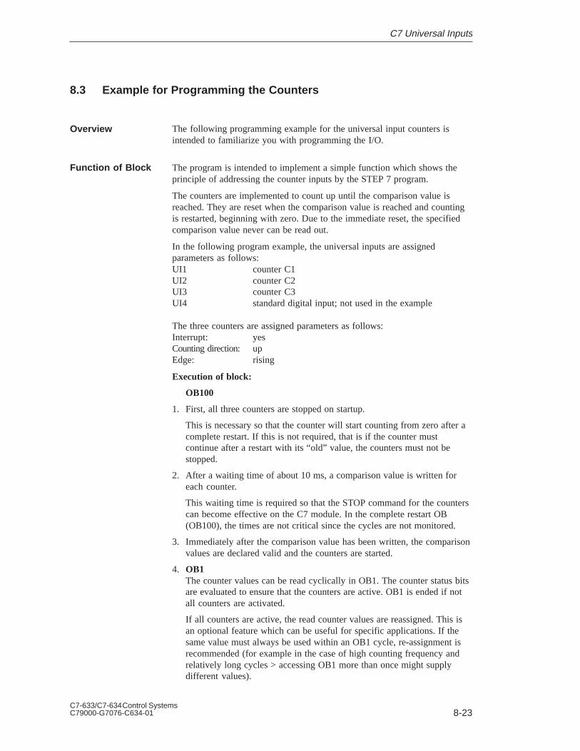
8-23C7-633/C7-634 Control SystemsC79000-G7076-C634-01
8.3 Example for Programming the Counters
The following programming example for the universal input counters isintended to familiarize you with programming the I/O.
The program is intended to implement a simple function which shows theprinciple of addressing the counter inputs by the STEP 7 program.
The counters are implemented to count up until the comparison value isreached. They are reset when the comparison value is reached and countingis restarted, beginning with zero. Due to the immediate reset, the specifiedcomparison value never can be read out.
In the following program example, the universal inputs are assignedparameters as follows:UI1 counter C1UI2 counter C2UI3 counter C3UI4 standard digital input; not used in the example
The three counters are assigned parameters as follows:Interrupt: yesCounting direction: upEdge: rising
Execution of block:
OB100
1. First, all three counters are stopped on startup.
This is necessary so that the counter will start counting from zero after acomplete restart. If this is not required, that is if the counter mustcontinue after a restart with its “old” value, the counters must not bestopped.
2. After a waiting time of about 10 ms, a comparison value is written foreach counter.
This waiting time is required so that the STOP command for the counterscan become effective on the C7 module. In the complete restart OB(OB100), the times are not critical since the cycles are not monitored.
3. Immediately after the comparison value has been written, the comparisonvalues are declared valid and the counters are started.
4. OB1The counter values can be read cyclically in OB1. The counter status bitsare evaluated to ensure that the counters are active. OB1 is ended if notall counters are activated.
If all counters are active, the read counter values are reassigned. This isan optional feature which can be useful for specific applications. If thesame value must always be used within an OB1 cycle, re-assignment isrecommended (for example in the case of high counting frequency andrelatively long cycles > accessing OB1 more than once might supplydifferent values).
Overview
Function of Block
C7 Universal Inputs
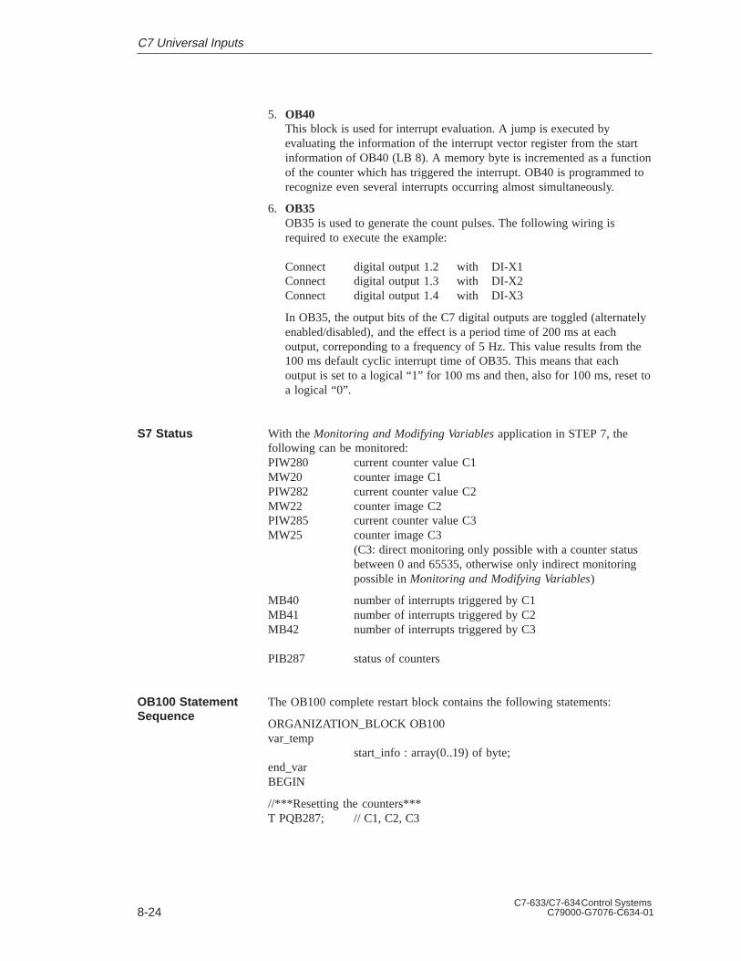
8-24C7-633/C7-634 Control Systems
C79000-G7076-C634-01
5. OB40This block is used for interrupt evaluation. A jump is executed byevaluating the information of the interrupt vector register from the startinformation of OB40 (LB 8). A memory byte is incremented as a functionof the counter which has triggered the interrupt. OB40 is programmed torecognize even several interrupts occurring almost simultaneously.
6. OB35OB35 is used to generate the count pulses. The following wiring isrequired to execute the example:
Connect digital output 1.2 with DI-X1Connect digital output 1.3 with DI-X2Connect digital output 1.4 with DI-X3
In OB35, the output bits of the C7 digital outputs are toggled (alternatelyenabled/disabled), and the effect is a period time of 200 ms at eachoutput, correponding to a frequency of 5 Hz. This value results from the100 ms default cyclic interrupt time of OB35. This means that eachoutput is set to a logical “1” for 100 ms and then, also for 100 ms, reset toa logical “0”.
With the Monitoring and Modifying Variables application in STEP 7, thefollowing can be monitored:PIW280 current counter value C1MW20 counter image C1PIW282 current counter value C2MW22 counter image C2PIW285 current counter value C3MW25 counter image C3
(C3: direct monitoring only possible with a counter status between 0 and 65535, otherwise only indirect monitoring possible in Monitoring and Modifying Variables)
MB40 number of interrupts triggered by C1MB41 number of interrupts triggered by C2MB42 number of interrupts triggered by C3
PIB287 status of counters
The OB100 complete restart block contains the following statements:
ORGANIZATION_BLOCK OB100var_temp
start_info : array(0..19) of byte;end_varBEGIN
//***Resetting the counters***T PQB287; // C1, C2, C3
S7 Status
OB100 StatementSequence
C7 Universal Inputs

8-25C7-633/C7-634 Control SystemsC79000-G7076-C634-01
CALL SFC 47 // wait so that STOP becomes effective(WT:=10000) // 10000 s = 10 ms
//***Setting comparison values***L 10; // set comparison value C1T PQW280;L 20; // set comparison value C2T PQW282;L 40; // set comparison value C3T PQW285;
//***Declaring comparison values valid and starting counter***L 3F; // declare comparison value valid and startT PQB287; // C1, C2, C3
END_ORGANIZATION_BLOCK
OB1 contains the following statements:
ORGANIZATION_BLOCK OB1var_temp
start_info : array(0..19] of byte;status : BYTE;
end_varBEGIN
//***Check whether all counters are active***L PIB287; // scanning status bitsT status;
A L20.4; // C1 signalled activeA L20.5; // C2 signalled activeA L20.6; // C3 signalled activeJC run;BEU;
//***Waiting time of 1 ms***CALL SFC47 // “Wait function”(WT:=1000); // 1000 s = 1 ms
//***Determining counter image (optional)***run: NOP 0;L PIW280; // C1T MW20;L PIW282; // C2T MW22;
either//*** Determining counter image for 16-bit counter ***L PIW285; // C3T MW25;
OB1 StatementSequence
C7 Universal Inputs

8-26C7-633/C7-634 Control Systems
C79000-G7076-C634-01
or//*** Determining counter image for 24-bit counter ***L PID284; // read in C3 (PIB284-286) and status byte (PIB287)S RD8; // transfer PIB287 bits from ACCUT MD24; // transfer ACCU or C3 to memory double word
END_ORGANIZATION_BLOCK
OB35 contains the following statements:
ORGANIZATION_BLOCK OB35var_temp
start_info : array(0..19) of byte;end_varBEGIN
AN Q1.2; // assigned to C1=Q1.2;
AN Q1.3; // assigned to C2=Q1.3;
AN Q1.4; // assigned to C3=Q1.4;
L QW0; // transfer QW0 immediately T PQW0;
END_ORGANIZATION_BLOCK
OB40 contains the following statements:
ORGANIZATION_BLOCK OB40var_temp
start_info : array[0..19] of byte;end_varBEGIN
//***Determining which input has triggered interrupt***
AN L8.0; // interrupt from C1?JC c2;
L MB40; // counts number of interrupts from C1 (up to 255)INC 1;T MB40;
c2:NOP 0;AN L8.1; // interrupt from C2?JC c3;
L MB41; // counts number of interrupts from C2 (up to 255)INC 1;T MB41;
OB35 StatementSequence
OB40 StatementSequence
C7 Universal Inputs

8-27C7-633/C7-634 Control SystemsC79000-G7076-C634-01
c3:NOP 0;AN L8.2; // interrupt from C3?BEB;
L MB42; // counts number of interrupts from C3 (up to 255)INC 1;T MB42;
END_ORGANIZATION_BLOCK
C7 Universal Inputs

8-28C7-633/C7-634 Control Systems
C79000-G7076-C634-01
C7 Universal Inputs

9-1C7-633/C7-634 Control SystemsC79000-G7076-C634-01
Data Set Description, I/O ParameterAssignment
Section Description Page
9.1 Data Set Description for Parameter Block of C7 AnalogI/O and Universal Inputs
9-2
Chapter Overview
9

9-2C7-633/C7-634 Control Systems
C79000-G7076-C634-01
9.1 Data Set Description for Parameter Block of C7 Analog I/O andUniversal Inputs
If a reassignment is to be performed during operation, then the validity andinter-relationships between the individual parameters must be checked by theuser program.
Incorrect value ranges of the parameters can result in incorrect behavior ofthe I/O. Table 9-1 lists the layout of the parameter data sets.
Table 9-1 Table with Data Set Descriptions Parameter Block
DS Byte Bit Default-Value
What Can Be Assigned Meaning of the Respective Bits
0 00 7 0 Enable diagnostics AO4 0=No 1=Yes
6 0 Enable diagnostics AO3 0=No 1=Yes
5 0 Enable diagnostics AO2 0=No 1=Yes
4 0 Enable diagnostics AO1 0=No 1=Yes
3
2
2
0
0
0
Enable diagnostics AI4
Enable diagnostics AI3
Enable diagnostics AI2
0=No 1=Yes
0=No 1=Yes
0=No 1=Yes
1 0 Enable diagnostics AI1 0=No 1=Yes
01 7..5 000 –
4 0 Enable diagn. interrupt module
3 0 Enable diagn. wire break AI4 0=No, 1=Yes (only if measurement range 4 to 20mA)
2 0 Enable diagn. wire break AI3 0=No, 1=Yes (only if measurement range 4 to 20mA)
1
0
0
0
Enable diagn. wire break AI2
Enable diagn. wire break AI1
0=No, 1=Yes (only if measurement range 4 to 20mA)
0=No, 1=Yes (only if measurement range 4 to 20mA)
02 0..7 00000000 Reserved Must always be zero, otherwise parameterassignment error
03 00000000 Reserved Must always be zero, otherwise parameterassignment error
1 04 7..6 00 AI2 –
5..4 01 Measurement range 00=Deactivated, 01=10 V, 10=20 mA,
11=4 to 20 mA
3..2 00 AI1 –
1..0 01 Measurement range 00=Deactivated, 01=10 V, 10=20 mA,
11=4 to 20 mA
Overview
Data Set Description, I/O Parameter Assignment

9-3C7-633/C7-634 Control SystemsC79000-G7076-C634-01
Table 9-1 Table with Data Set Descriptions Parameter Block
05 7..6 01 AI4 –
5..4 00 Measurement range 00=Deactivated, 01=10 V, 10=20 mA,
11=4 to 20 mA
3..2 01 AI3 –
1 05 1..0 00 Measurement range 00=Deactivated, 01=10 V, 10=20 mA,
11=4 to 20 mA
06 7..2
1..0
000000
00
–
Enable cyclic interrupt 00=No cyclic interrupt
01=Time cyclic interrupt(only if byte 7 <> 1)
10=Cycle end interrupt (only if all AIx are notdeactivated)
07 7..4
3..0
0000
0001
–
Cycle time 0=16 ms, 1=Free-running, 6=3 ms, 7=3.5 ms,
8=4 ms etc. (increment 0.5 ms up to 15.5 ms)
08 7..6 00 Univ. DI1 –
5 0 Direction 0=Up, 1=Down (only if mode=010)
4 0 Edge 0=Rising edge, 1=Falling edge
3 0 Hardware interrupt 0=No, 1=Yes
2..0 000 Mode 000=General DI, 001=Interrupt DI,
010=Counter (CI), 101=External gate counter
09 7..6 00 Univ. DI2 –
5 0 Direction 0=Up, 1=Down (only if mode=010)
4 0 Edge 0=Rising edge, 1=Falling edge
3 0 Hardware interrupt 0=No, 1=Yes
2..0 000 Mode 000=General DI, 001=Interrupt DI,
010=Counter (CI), 101=External gate counter
10 7..6 00 Univ. DI3 gate time 00=0.1 s, 01=1 s, 10=10 s (only if mode=010)
5 0 Direction 0=Up, 1=Down (only if mode =010)
4
3
0
0
Edge
Hardware interrupt
0=Rising edge, 1=Falling edge
0=No, 1=Yes
2..0 000 Mode 000=General DI, 001=Interrupt DI,
010=Counter (CI), 011=Frequency counter (FC)
100=Period duration counter (PC), 101=Externalgate counter
11 7..5
4
3
2..0
00000
0
0
0
Univ. DI4 –
Edge
Hardware interrupt
Mode
0=Rising edge, 1=Falling edge
0=No, 1=Yes
000=General DI, 001=Interrupt DI
12 7..6 00 AO2 Reaction to CPU STOP 00=Voltage/power idle (substitute value = 0)
01=Retain last value, 10=Global substitute value (byte 14 to 15)
Data Set Description, I/O Parameter Assignment

9-4C7-633/C7-634 Control Systems
C79000-G7076-C634-01
Table 9-1 Table with Data Set Descriptions Parameter Block
5..4 01 Output area 00=Deactivated, 01=10 V, 10=20 mA,11=4 to 20 mA
1 3..2
1..0
00
01
AO1 Reaction to CPU STOP
Output area
00=Voltage/power idle (substitute value = 0)
01=Retain last value, 10=Global substitute value (byte 14 to 15)
00=Deactivated, 01=10 V, 10=20 mA,11=4 to 20 mA
13 7..6 00 AO4 Reaction to CPU STOP 00=Voltage/power idle (substitute value = 0)
01=Retain last value, 10=Global substitute value (byte 14 to 15)
5..4 01 Output area 00=Deactivated, 01=10 V, 10=20 mA,11=4 to 20 mA
3..2
1..0
00
01
AO3 Reaction to CPU STOP
Output area
00=Voltage/power idle (substitute value = 0)
01=Retain last value, 10=Global substitute value (byte 14 to 15)
00=Deactivated, 01=10 V, 10=20 mA,11=4 to 20 mA
14 ooooH Global substitute value forAO1 to AO4
(only if “global substitute value” active on at leastone of the AO)
15
Data Set Description, I/O Parameter Assignment
10-1C7-633/C7-634 Control SystemsC79000-G7076-C634-01
I/O Diagnostics
In this section, you will learn which diagnostic messages you can set andhow the diagnostic buffer is structured.
The diagnostics of the C7 analog I/O are described.
This chapter also tells you how you can correct the reported errors for themost important diagnostic messages of the C7 analog I/O with universalinputs.
The term “module” refers here to a unit consisting of the analog I/O and theuniversal inputs.
Section Description Page
10.1 Diagnostic Messages 10-2
10.2 Diagnostic Data of the C7 Analog I/O and UniversalInputs
10-4
10.3 Dependencies and Reactions of the DiagnosticEvaluation
10-8
In This Chapter
ChapterOverview
10

10-2C7-633/C7-634 Control Systems
C79000-G7076-C634-01
10.1 Diagnostic Messages
The C7 CPU possesses a diagnostic buffer in which detailed information isprovided for all diagnostic events in the order of their occurrence. Thecontents of the diagnostic buffer is preserved even after a memory reset onthe C7 CPU. The diagnostic entries in the diagnostic buffer can be read andinterpreted by the user program.
Errors in the system can be evaluated after a long time delay using thediagnostic buffer in order be able to identify the cause of a STOP, forexample, or to trace and assign the occurrence of individual diagnosticevents.
Diagnostic events can be:
Errors in an I/O (module)
System errors in the C7 CPU
Change in operating modes (for example, from RUN to STOP)
Program errors in the CPU program
The I/O diagnostics are divided into two groups:
Standard diagnostics (general malfunction of the C7 analog I/O moduleand universal inputs)
Module-specific diagnostics
The standard diagnostics are always entered into the diagnostic buffers of theC7 CPU after the occurrence of a diagnostic interrupt. The requirement isthat the module is able to diagnose.
The module-specific diagnostics provide detailed information regarding thetype and possible cause of the error. This information can be called up by theuser program by means of special system calls. The requirement is thatdiagnostics have been enabled (default setting is always “no” in this case).
You can set whether the analog I/O diagnostic messages should be generatedusing STEP 7.
Using the STEP 7 application Configuring Hardware, you can also assignparameters to the diagnostic behavior of the analog I/O, i.e. you set whetherthe analog I/O diagnostic messages should be sent to the C7 CPU on request.Furthermore, you can assign parameters to define whether the moduleshould trigger a diagnostic interrupt in the C7 CPU after the occurrence of anerror.
Overview
Advantages
Diagnostic Events
C7 CPU I/ODiagnostics
Assigning I/ODiagnosticParameters
I/O Diagnostics

10-3C7-633/C7-634 Control SystemsC79000-G7076-C634-01
In the diagnostic information, we differentiate between permanent andtemporary diagnostic errors.
Permanent diagnostic errors cannot be influenced by the user programand can only be removed by resetting the C7 CPU (memory reset andcomplete restart) or equipment exchange (after a fault).
Temporary diagnostic errors disappear automatically after a renewedmeasurement (ADC error, overrange or underrange error), can beremoved by the user program (if necessary, by assigning parameters viaSFC55 during operation) or by hand at the connections (correcting thewiring).
Diagnostic messages will be entered into the diagnostic buffer only if thediagnostic interrupt OB (OB82) occurs. The requirement is that theparameter “diagnostic interrupt enable = yes” was assigned. Then you canread out the detailed diagnostic messages in addition to the standarddiagnostic information using the STEP 7 application Module Information(see Manual /231/). No entry is made in the diagnostic buffer of the C7 CPUin all other cases. Therefore the diagnostic message cannot be read out.
DiagnosticInformation (I/O)
Read DiagnosticMessages
I/O Diagnostics

10-4C7-633/C7-634 Control Systems
C79000-G7076-C634-01
10.2 Diagnostic Data of the C7 Analog I/O and Universal Inputs
This section describes the C7 analog I/O and universal inputs with regard totheir module-specific diagnostic messages.
Table 10-1 provides an overview of the channel-specific diagnostic messagesof the analog input.
The diagnostic information is allocated to the individual channels.
Table 10-1 Diagnostic Message of the Analog Input
Diagnostic message Analog Input
Parameter assignment error Yes
Common mode error No
P short circuit No
M short circuit No
Wire break (only for 4 to 20mA by software) Yes
Reference error No
Underrange (underflow) Yes
Overrange (overflow) Yes
Only one group error exists for the analog output.Possible causes of the group error could be:
Parameter error
Substitute value is connected
The diagnostic area consists of:
Data set 0: the standard diagnostic bytes (0 to 3)
Data set 1: the channel-specific diagnostic bytes (for enabled diagnostics).
– Bytes 4 to 7 and bytes 8 to 11 - channel and individual informationanalog input (AI) diagnostics
– Bytes 12 to 15 - channel information- analog output (AO) diagnostics
Overview
Analog InputDiagnostics
Analog OutputDiagnostics
Layout ofDiagnostic Area ofthe Module
I/O Diagnostics

10-5C7-633/C7-634 Control SystemsC79000-G7076-C634-01
Table 10-2 illustrates the structure of the diagnostic area and the meaning ofthe individual entries.
Table 10-2 Structure of the Diagnostic Area
Byte Bit Meaning Explanation ValueRange
00 0 Module fault 1 = error occurred, 0 = everything OK 0 | 1
1 Internal error 1 = watchdog, EPROM, ADC error 0 | 1
2 External error 1 = error at AI or AO 0 | 1
3 Channel error 1 = with byte 0/bit 2 and channel-specificdiagnostic bytebyte 4 ...
0 | 1
4 External auxiliary voltage missing (Cannot be checked) 0
5 Front plug missing (Cannot be checked) 0
6 Module not assigned parameters Normal state (standard parameters set)byte 0/bit 0=0 ****)
0 | 1
7 Incorrect parameters 1 with bit 8,9,10,11.0 or 15.0 (Standardparameters set for channel
0 | 1
01 0 Module class SM type class
1 Module class SM type class 5
2 Module class SM type class
3 Module class SM type class
4 System-oriented channel-specificdiagnostic info.
Yes 1
5 User-defined diagnostic info. (diag.info. not configured by system)
No 0
6 –– –– 0
7 –– –– 0
02 0 Coding connector incorrect/missing–– 0
1 Communications failure Error during transfer of parameters/input data 0
2 Operating mode RUN/STOP 0
3 Watchdog activated with bit 1 of byte 0 *) **) 0 | 1
4 Internal voltage failed –– 0
5 Battery 1 empty –– 0
6 Entire backup battery failed –– 0
7 –– –– 0
03 0 Rack failure –– 0
1 Processor failure –– 0
2 EEPROM error Serial calibration EEPROM for analog measuredvalue calibration, set with bit 1 of byte 0 *) **)
0 | 1
3 RAM error –– 0
4 ADC error with bit 1 of byte 0 *) 0
I/O Diagnostics

10-6C7-633/C7-634 Control Systems
C79000-G7076-C634-01
Table 10-2 Structure of the Diagnostic Area
Byte ValueRange
ExplanationMeaningBit
5 Fuse failure –– 0
6 Hardware interrupt lost –– 0
7 –– 0
Channel-Specific Diagnostic Entries
04 0..7 Channel type AI of the following channel-specific diagnostic information 71H
05 0..7 Number of analog input channels 4
06 0..7 Number of diagnostic bits perchannel
8
07 Channel Vector Channel Group AI
0 Error assigning parameters to DI1 0 = no, 1 = yes 0 | 1
1 Error assigning parameters to DI2 0 = no, 1 = yes 0 | 1
2 Error assigning parameters to DI3 0 = no, 1 = yes 0 | 1
3 Error assigning parameters to DI4 0 = no, 1 = yes 0 | 1
4 Error in channel AI1 0 = no, 1 = yes 0 | 1
5 Error in channel AI2 0 = no, 1 = yes 0 | 1
6 Error in channel AI3 0 = no, 1 = yes 0 | 1
7 Error in channel AI4 0 = no, 1 = yes 0 | 1
08 Channel-Specific Diagnostic Byte AI1
0 Parameter error in parameters forchannel
0 = no, 1 = yes *) 0 | 1
1..3 –– 000
4 Wire break in software 0 = no, 1 = yes (only for 4 to 20mA) 0 | 1
5 –– 0
6 Measurement underrange 0 = no, 1 = yes (underflow) 0 | 1
7 Measurement overrange 0 = no, 1 = yes (overflow) 0 | 1
09 Channel-Specific Diagnostic Byte AI2
0 Parameter error in parameters forchannel
0 = no, 1 = yes *) 0 | 1
1..3 –– 000
4 Wire break in software 0 = no, 1 = yes (only for 4 to 20mA) 0 | 1
5 –– 0
6 Measurement underrange 0 = no, 1 = yes (underflow) 0 | 1
7 Measurement overrange 0 = no, 1 = yes (overflow) 0 | 1
I/O Diagnostics
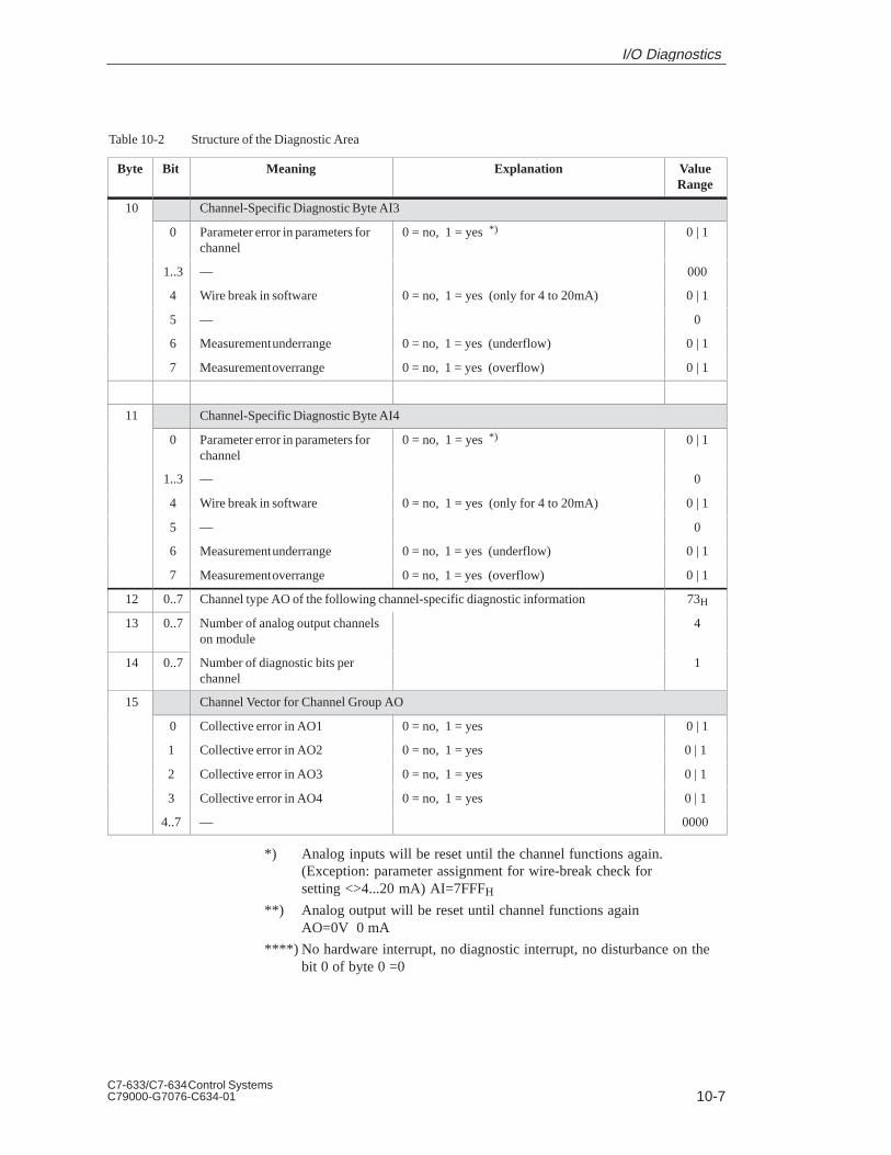
10-7C7-633/C7-634 Control SystemsC79000-G7076-C634-01
Table 10-2 Structure of the Diagnostic Area
Byte ValueRange
ExplanationMeaningBit
10 Channel-Specific Diagnostic Byte AI3
0 Parameter error in parameters forchannel
0 = no, 1 = yes *) 0 | 1
1..3 –– 000
4 Wire break in software 0 = no, 1 = yes (only for 4 to 20mA) 0 | 1
5 –– 0
6 Measurement underrange 0 = no, 1 = yes (underflow) 0 | 1
7 Measurement overrange 0 = no, 1 = yes (overflow) 0 | 1
11 Channel-Specific Diagnostic Byte AI4
0 Parameter error in parameters forchannel
0 = no, 1 = yes *) 0 | 1
1..3 –– 0
4 Wire break in software 0 = no, 1 = yes (only for 4 to 20mA) 0 | 1
5 –– 0
6 Measurement underrange 0 = no, 1 = yes (underflow) 0 | 1
7 Measurement overrange 0 = no, 1 = yes (overflow) 0 | 1
12 0..7 Channel type AO of the following channel-specific diagnostic information 73H
13 0..7 Number of analog output channelson module
4
14 0..7 Number of diagnostic bits perchannel
1
15 Channel Vector for Channel Group AO
0 Collective error in AO1 0 = no, 1 = yes 0 | 1
1 Collective error in AO2 0 = no, 1 = yes 0 | 1
2 Collective error in AO3 0 = no, 1 = yes 0 | 1
3 Collective error in AO4 0 = no, 1 = yes 0 | 1
4..7 –– 0000
*) Analog inputs will be reset until the channel functions again. (Exception: parameter assignment for wire-break check for setting <>4...20 mA) AI=7FFFH
**) Analog output will be reset until channel functions againAO=0V 0 mA
****) No hardware interrupt, no diagnostic interrupt, no disturbance on the bit 0 of byte 0 =0
I/O Diagnostics

10-8C7-633/C7-634 Control Systems
C79000-G7076-C634-01
10.3 Dependencies and Reactions of the Diagnostic Evaluation
The diagnostic entries are interdependent. For example, the message for theerror “wire break” can only become effective if the diagnostic entries“external error” and “channel error” are set simultaneously.
These dependencies are illustrated in Table 10-3.
Table 10-3 Dependencies and Reactions of the Error Entries
Byte 0 / Bit 0 = 1 Module error
Byte 0 / Bit 1 = 1 Internal error
Byte 2 / Bit 3 = 1 Watchdog (R)
Byte 3 / Bit 2 = 1 EEPROM error (R)
Byte 3 / Bit 4 = 1 ADC error (M/R) (R)
Byte 0 / Bit 2 = 1 External error
Byte 0 / Bit 3 = 1 Channel error
Byte 7 Evaluate channel vector if req.
Wire breakByte 8, 9, 10, 11: Bit 4 = 1 channel-specific diagnosticbyte AI (E/P)
UnderrangeByte 8, 9, 10, 11: Bit 6 = 1 channel-specific diagnosticbyte AI (E/P/M)
OverrangeByte 8, 9, 10, 11: Bit 7 = 1 channel-specific diagnosticbyte AI (E/P/M)
Byte 0 / Bit 7 = 1 Incorrect parameters
Byte 8,9,10,11 / Bit 0 = 1 channel-specific diagnostic byte AI (P)
Byte 15 / Bit 0 = 1 Collective error AO (only parameter errorpossible) (P)
Byte 0 / Bit 6 = 1 Module not assigned parameters
Legend:E = temporary, can be removed by hand at connectionP = permanent, can be reset by assigning correct parametersR = permanent, can be removed by RESET (memory reset and
complete restart of C7 CPU) or by exchanging equipmentM = temporary, disappears after new measurement
Overview
Dependency ofError Entry
I/O Diagnostics
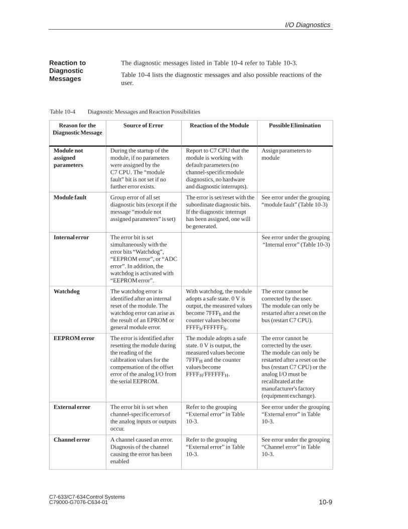
10-9C7-633/C7-634 Control SystemsC79000-G7076-C634-01
The diagnostic messages listed in Table 10-4 refer to Table 10-3.
Table 10-4 lists the diagnostic messages and also possible reactions of theuser.
Table 10-4 Diagnostic Messages and Reaction Possibilities
Reason for theDiagnostic Message
Source of Error Reaction of the Module Possible Elimination
Module notassignedparameters
During the startup of themodule, if no parameterswere assigned by theC7 CPU. The “modulefault” bit is not set if nofurther error exists.
Report to C7 CPU that themodule is working withdefault parameters (nochannel-specific modulediagnostics, no hardwareand diagnostic interrupts).
Assign parameters tomodule
Module fault Group error of all setdiagnostic bits (except if themessage “module notassigned parameters” is set)
The error is set/reset with thesubordinate diagnostic bits.If the diagnostic interrupthas been assigned, one willbe generated.
See error under the grouping“module fault” (Table 10-3)
Internal error The error bit is setsimultaneously with theerror bits “Watchdog”,“EEPROM error”, or “ADCerror”. In addition, thewatchdog is activated with“EEPROM error”.
See error under the grouping “Internal error” (Table 10-3)
Watchdog The watchdog error isidentified after an internalreset of the module. Thewatchdog error can arise asthe result of an EPROM orgeneral module error.
With watchdog, the moduleadopts a safe state. 0 V isoutput, the measured valuesbecome 7FFFh and thecounter values becomeFFFFh/FFFFFFh.
The error cannot becorrected by the user.The module can only berestarted after a reset on thebus (restart C7 CPU).
EEPROM error The error is identified afterresetting the module duringthe reading of thecalibration values for thecompensation of the offseterror of the analog I/O fromthe serial EEPROM.
The module adopts a safestate. 0 V is output, themeasured values become7FFFH and the countervalues becomeFFFFH/FFFFFFH.
The error cannot becorrected by the user. The module can only berestarted after a reset on thebus (restart C7 CPU) or theanalog I/O must berecalibrated at themanufacturer’s factory(equipment exchange).
External error The error bit is set whenchannel-specific errors ofthe analog inputs or outputsoccur.
Refer to the grouping“External error” in Table10-3.
See error under the grouping“External error” in Table10-3.
Channel error A channel caused an error. Diagnosis of the channelcausing the error has beenenabled
Refer to the grouping“External error” in Table10-3.
See error under the grouping“Channel error” in Table10-3.
Reaction toDiagnosticMessages
I/O Diagnostics

10-10C7-633/C7-634 Control Systems
C79000-G7076-C634-01
Table 10-4 Diagnostic Messages and Reaction Possibilities
Reason for theDiagnostic Message
Possible EliminationReaction of the ModuleSource of Error
Wire break Requirement:The measurement range0 to 20 mA has been set forthe channel.
If a wire-break check hasbeen assigned, then the erroris identified by evaluation ofthe input current of theanalog input channel (<1.6mA).
An error counter will beincremented. If the errorcounter reaches a fixed valueof 3, then the error “wirebreak” is reported.
Check the connection of theappropriate measurementchannel.
Overflow The error is identified afterthe comparison of themeasured value (incl.correction calculation).Measurement >=positiveoverflow range.
The bit is set and reset againwhen the measurementdecreases.
Check the connection of theappropriate input channel ortransducer.
Underflow The error is identified afterthe comparison of themeasured value (incl.correction calculation).Measurement >= negativeoverflow range. That is<0 mA for 4 to 20 mA.
The bit is set and reset againwhen the measurementbecomes valid.
Check the connection of theappropriate input channel ortransducer.
IncorrectParameters
The error is identified whenchecking the parameter afterreading and processing theparameter area.
The measurement 7FFFH isset in the incorrectlyconfigured measurementchannel and thecorresponding diagnostic bitset or, for an output channel,0 V /0 mA is output and thecorresponding bit set. If themodule had not beenassigned parameters and theassignment is correct, thenthe bit “incorrect parameter”is reset and (if diagnosticinterrupt= yes) a diagnosticinterrupt reported to the C7CPU.
Assign correct parameters.
Hardware InterruptLost
The module is sending moreinterrupts than can beprocessed by the CPU.
Bit 6 in byte 3 “hardwareinterrupt lost” is set for atleast 500 ms, if no furtherhardware interrupt is lostduring this time period.
Change parameter settingsfor counter values
I/O Diagnostics

11-1C7-633/C7-634 Control SystemsC79000-G7076-C634-01
Maintenance
Section Description Page
11.1 Changing the Backup Battery 11-2
11.2 Replacing the C7 11-4
ChapterOverview
11
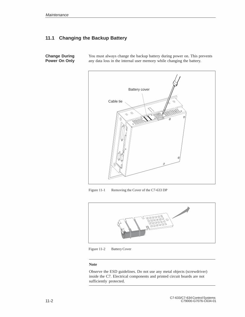
11-2C7-633/C7-634 Control Systems
C79000-G7076-C634-01
11.1 Changing the Backup Battery
You must always change the backup battery during power on. This preventsany data loss in the internal user memory while changing the battery.
Battery cover
Cable tie
Figure 11-1 Removing the Cover of the C7-633 DP
Figure 11-2 Battery Cover
Note
Observe the ESD guidelines. Do not use any metal objects (screwdriver)inside the C7. Electrical components and printed circuit boards are notsufficiently protected.
Change DuringPower On Only
Maintenance

11-3C7-633/C7-634 Control SystemsC79000-G7076-C634-01
Proceed as follows to change the backup battery:
1. Unscrew the cover of the C7 battery compartment (see Figure 11-1).
2. Lift the cover up and to the right (see Figure 11-2). Make sure you raisethe cover only as far as the battery connections allow.
3. Unplug the battery connector from the old backup battery (see Figure11-3).
4. Loosen the cable ties with which the battery is attached to the cover (seeFigure 11-3).
5. Attach the new backup battery to the cover using the cable ties.
6. Plug the battery connector of the new battery into the two-pin plugconnector. The battery connector is coded to prevent it being pluggedincorrectly (see Figure 11-3).
7. Replace the battery cover on the C7 with the clips to the left and screwthe cover tight again.
Figure 11-3 Inserting the Backup Battery
We recommend that you change the battery every year.
Note
Observe the regulations or guidelines concerning the handling and disposalof lithium batteries enclosed with the battery.
Store your backup batteries in a cool, dry place. Backup batteries can bestored for up to five years.
Service Life of theBackup Battery
Storage of BackupBatteries
Maintenance

11-4C7-633/C7-634 Control Systems
C79000-G7076-C634-01
11.2 Replacing the C7
On-site repair of the C7 has not been provided for. For this reason, adefective C7 must be replaced.
The following components must be available in order to replace a C7:
Hardware
Programming device/PC with MPI interface module
Connection cable (MPI and RS 232/TTY)
Development tools
STEP 7
ProTool or ProTool/Lite
User software (stored outside the C7)
OP configuration
CPU user program (if data from the C7 CPU can no longer be read and nomemory card is inserted)
Dismantle the device in the opposite order to the installation. Proceed asfollows to remove the C7:
1. Connect a programming device/PC to the multipoint interface.
2. Use STEP 7 to save the user program on the C7 CPU to a programmingdevice/PC or remove the memory card on which the CPU user program isstored.If the C7 CPU is defective and the user program can no longer be readout, remove the C7 without any further safety measures.
The configuration loaded on the C7 cannot be displayed. It must be availableon a programming device/PC.
Introduction
Requirement
Removal
Maintenance
11-5C7-633/C7-634 Control SystemsC79000-G7076-C634-01
The mechanical and electrical installation is as described in Sections 2.2 and2.3. Once you have obtained a new C7, install it as follows:
1. Connect a programming device/PC to the multipoint interface.
2. Perform a memory reset on the C7 CPU.
3. Without a memory card: Transfer the previously saved CPU user program from the programmingdevice/PC with the relevant data to the C7 CPU (with STEP 7).With a memory card: Insert the memory card and perform another memory reset (MRES) on theC7 CPU.
4. Connect the C7 operator panel to the serial interface of the programmingdevice/PC.
5. Load your configuration onto the C7 operator panel using ProTool orProTool/Lite.
6. Start the CPU user program (by selecting a CPU mode).
Installation
Maintenance

11-6C7-633/C7-634 Control Systems
C79000-G7076-C634-01
Maintenance

A-1C7-633/C7-634 Control SystemsC79000-G7076-C634-01
System Messages
This chapter lists the most important system messages, when they occur and,where applicable, how you can eliminate the error.
C7 system messages can be subdivided into various categories.
The information as to which category a system message belongs to iscontained in the message number as indicated below.
Message text
Message number
0 Driver error
1 Startup message
2 Warning3 Information message
4 Operator error
5 Other message
6 Configuration error7 Internal error
The message category enables you to identify the general area in which thecause of the fault is to be found.
Below you will find a selection of system messages listed together withdetails of under what circumstances they occur and, where applicable, howthe cause of the fault can be eliminated.
Self-explanatory system messages are not included.
Note
System messages are displayed in the language selected in the configuration.If the C7 does not have access to any configuration data, the messages aredisplayed in English.
In This Chapter
Message number
A

A-2C7-633/C7-634 Control Systems
C79000-G7076-C634-01
In the case of all system messages that relate to “internal errors”, please follow the procedure outlined below.
a) Switch off the C7 and then restart it again.
b) During startup, set the C7 to download mode, retransfer the configurationand then restart the C7 again.
c) If the fault occurs again, please contact your nearest Siemensrepresentative. When doing so, please quote the number of the error thathas occurred and any variables referred to in the message.
Message Cause Remedy
Please wait Mode change in progress or recipe functionstarted
Ready for transfer
Waiting for data from programming device/PC
Data transfer Data transfer between programming device/PCand C7 in progress
Firmware notcompatible
The firmware can not be used for the currentconfiguration
EPROMmemory failure
Memory module defective or internalhardware fault
Send unit for repair quoting details of errormessage
RAM memoryfailure
g
Flash memoryfailure
Memory module defective or transmissionerror
Retransfer configuration or send C7 for repair
Procedure for“Internal Errors”
System Messages

A-3C7-633/C7-634 Control SystemsC79000-G7076-C634-01
Message Cause Remedy:
005 Internal error:
Error message returned if nothing configured for a systemmessage
006 Error during data transfer in download mode. Twovariables are transferred with this message which contain information about the function in which the error has occurred (variable 1) and the cause of the error (variable 2).
Variable 1:0 Initialize function1 Receive data2 Send data3 Send message block4 Terminate function
Variable 2:1 Internal error3 Timeout error5 Parity error6 Framing error7 Overrun error8 Break in line9 Receive buffer overflow10 Control character error when receiving11 Logging error
Repeat data transfer after first checking thephysical connection if necessary.
026...029 Storage medium not ready, contains errors or status undefinable.
Reset hardware, remove then refit Flashmemory module or carry out hardware test.
030 Storage medium not initialized. Switch to download mode.
032 Error accessing module, Flash may not be supported orinitialized by incorrect C7.
Check whether module is properly insertedand compatible.
If restoring: repeat backup with correct C7.
033 Internal Flash memory initialized; configuration datadeleted, some recipe data preserved.
Retransfer configuration.
034 Inserted submodule initialized, all stored data deleted. Retransfer configuration.
035 Size of selected recipe memory has been reduced. The reduced-size recipe memory can not beused and all data records must be deleted.The recipe memory is only initialized whenrequested.
040 Driver error
If FAP is set, the character delay time setting may be tooshort.
Check physical connection to PLC.
Alter character delay time.
041 Fault in connection to PLC.
Possible causes:– Fault on the transmission link, e.g. connecting cable
defective– Incorrect interface parameters set on C7 or on
communication partner.
System Messages

A-4C7-633/C7-634 Control Systems
C79000-G7076-C634-01
Remedy:CauseMessage
043 Data transfer error. A variable indicating the cause of thefault is transferred with this message.
Variable:0 Timeout error1 Framing error (receiving)2 Overrun error3 Parity error4 No connection established5 Checksum error (receiving)6 Unexpected characters received7...11 Internal errors12 Receive data block too large13 Memory area not available on PLC
Repeat the data transfer. Before doing so,check the physical connection/configuredinterface parameters if necessary.
044 Fault in connection to PLC.
Possible causes:– Fault on the transmission link, e.g. connecting cable
defective– Incorrect interface parameters set on C7 or on
communication partner.
045 No connection to PLC established. Set different CPU using the menu command“System” and the “Parameters” button in thedialog box which appears.
100 Restart due to RAM failure.
101 Restart following termination of COM-UNI mode.
103 Startup following cancellation of COM-UNI mode.
104 Transfer cancelled by operator. Connection with C7 is stillopen, the C7 is waiting.
105 Fault resulting in wait message has been eliminated.
107 Restart following activation of COM-UNI mode.
108 C7 is in download mode.
109 Restart after change of operating mode from offline toonline.
110 C7 is in “normal” mode.
113, 114 PLC has been restarted.
115 Establishing logical link to PLC.
117 Connection to PLC is OK again following a fault.
119 Automatic restart.
120 Restart after change of S5/S7 protocol.
124 Restart following selection of different language.
130 Startup due to loop-through operation when online.
132 Startup due to loop-through operation when offline.
129 SINEC L1 or SINEC L2 parameter has been changed.
134 Restart due to offline operation.
136 PLC not responding. Check program sequence on PLC.
Check physical connection.
System Messages

A-5C7-633/C7-634 Control SystemsC79000-G7076-C634-01
Remedy:CauseMessage
138 Data block not available on PLC Set up relevant memory area.
200 Battery power no longer sufficient for internal data bufferon C7.
Battery on memory card is discharged, data may no longerbe readable.
Replace battery.
Note:
Replace the battery while the unit isswitched on in order to prevent loss of data.
201 Hardware fault in timer. Send unit for repair.
202 Error reading date. Send unit for repair.
203 Error reading time. Send unit for repair.
204 Error reading day. Send unit for repair.
205 Printer not ready and internal storage of print jobs is nolonger possible.
Make sure printer is ready or disablemessage logging.
206 Printer not ready. Print job placed in temporary storage.Make sure printer is ready.
207 Buffer printout or print screen function cancelled. Check printer, cable, and connectors.
210 Internal error
C7 co-ordination area not receivable during startup.
Press restart button.
212 Internal error
Bit for changing operating mode has been inverted erroneously.
Restart C7.
213 Offline mode not possible at present. Try changing of operating mode again later.
214 The job number sent by the PLC or configured in a function field is too large.
Check PLC program and configured screen.
217, 218 Overlapping specified/actual values. Check configuration of actual/specified values in the process link.
219 Hardware fault: relay or port could not be set. Send unit for repair.
220 Print buffer overflow due to overload. Logging notpossible.
Messages have been lost.
221 Print buffer overflow due to overload. Printout of overflow messages not possible.
Messages have been lost.
222 Warning: the event message buffer is full apart from thespecified remaining buffer space.
Clear the buffer or configure a smaller sizefor the remaining buffer space.
224 The event message buffer has overflowed. If a printer is connected and buffer overflowhas been configured, the overflow messageswill automatically be printed out.
225 Warning: the interrupt message buffer is full apart from thespecified remaining buffer space.
Clear the buffer or configure a smaller sizefor the remaining buffer space.
227 The interrupt message buffer has overflowed. If a printer is connected and buffer overflowhas been configured, the overflow messageswill automatically be printed out.
229 No keyboard connected (internal keyboard with ribboncable).
230 The minimum value is greater than the maximum value forvariable limits.
Correct the limit settings.
231 The minimum value is equal to the maximum value forvariable scales.
Correct the scale on the C7.
System Messages

A-6C7-633/C7-634 Control Systems
C79000-G7076-C634-01
Remedy:CauseMessage
250 You can not switch to the desired operating mode. Check parameters of PLC job.
251 Error transferring data record to PLC. Check recipe configuration.
252 Function can not be executed as a function of the samegroup has not yet been completed (e.g.: setpoint entry isactive, password list can not be opened).
Wait until preceding function has been completed (or terminate function) and thencall desired function again.
253 Access to data medium is not possible. 1. Floppy drive not present,
2. Floppy is read only,
3. Disk is not formatted.
254 The disk must be formatted before a data record can besaved for the first time.
First format the disk.
255 Not enough space on disk for this data record. Delete data records that are no longer required.
256 Not enough system memory available to execute the desired function.
Try activating function again. Check configuration.
1. Move function to a different screen.
2. Simplify screen structure.
3. Do not use any trends on the screen together with this function.
257 Data record has been stored with a different version stampthan defined in the current configuration.
If you are continuing to use the data records,the old version number must be entered in the recipe configuration.
Caution:
The structure of the recipe determines theassignment of data to a data record.
258 A parameter record has been selected as a recipe. Parameter records can not be edited directly.
Only individual data records of a parameterrecord can be edited.
259 Transfer of a data record to the PLC is taking too long.
Example:
PLC is not acknowledging data record or very large datarecords are being transferred.
Check PLC program. In the case of largedata records no modifications are necessaryas the function is being processed correctly.
260 Operating mode of PLC does not match the configuration.Change operating mode of PLC.
261 The data in this data record are no longer consistent and itcan therefore no longer be used.
Edit data record and check that all entriesare correct.
262 Password or query window already in use by anotherfunction.
Complete first function then execute desiredfunction again.
263 Specified remaining buffer space for messages has beenreached.
Configure smaller remaining buffer space,clear event/interrupt message buffer.
264 Message buffer overflow. The overflow messages are printed out if sospecified in the configuration.
265 The number of passwords issued has already reached 50.You can not enter any more passwords.
If you wish to issue additional passwords,you must first delete some of the existingones.
266 The field configured in the PLC job does not exist. Change the parameters of the PLC job andretransfer the configuration.
System Messages

A-7C7-633/C7-634 Control SystemsC79000-G7076-C634-01
Remedy:CauseMessage
303 Fault in connection with PLC.
S5: this error may occur when transferring large data records. In such cases the watchdog is activated.
Check PLC status.
S5: set value in data word 98 to at least2000.
304 Illegal S5 job number or job parameters in a function field.
305 Data block number missing. Set up data block or change configuration.
306 Incorrect CPU specified under the menu command“System,” “Parameters” button in the dialog box whichappears.
Change configuration and retransfer.
307 ...311
Variable not present on PLC Check configuration of process link.
312 The printer is already processing a print job and cannotaccept this next job at present.
Wait until the printer is free again and repeatthe print job.
313 Information message: print job completed.
314 S7 diagnostic buffer not present. The CPU has no diagnostic buffer (hardware problem).
315 No information text available.
316 Active password level insufficient for menu item Enter password with higher password level.
317 Input is password-protected. Enter password.
318 Incorrect password entered when attempting to log in.
319 An existing password was entered when editing the password.
Enter a different password.
320 You have attempted to alter the level of the supervisorpassword or to delete it.
321 You have attempted to alter the level of an invalid password.
First enter the password then specify thelevel.
322 The password entered is too short. Password must be at least three characterslong.
323 You have pressed <– Statistics or Message Text –> on abuffer screen but there is no entry for the current message.
––
324 The entry number specified does not exist on the selectedscreen.
––
325 The FM/NC (= MPI partner) has no alarm message buffer.A node does not have the required functional capability.
326 You have attempted to collect a recipe number other thanthe active recipe number from the PLC.
Select the appropriate recipe number.
327 Recipe number not present when selecting a recipe. Configure missing recipe or select a different one.
328 Recipe number >99 when selecting a recipe.
329 The same number has been entered for source and destination on the “Data Record Transfer” screen.
Enter different numbers.
330 Full details of source and destination not entered wheninitiating data record transfer function.
331 The data record specified as the source does not exist.
332 Data record number >99 when selecting a recipe screen.
System Messages

A-8C7-633/C7-634 Control Systems
C79000-G7076-C634-01
Remedy:CauseMessage
333 Data record number not present when selecting a recipescreen.
335 Information message: alarm message will be suppressed.
336 No process screens have been configured.
337 No recipes have been configured.
338 C7 can not establish a connection to the printer. 1. Printer is not switched on.
2. Printer is not ready.
3. Connecting lead between printer <––>C7 is not connected or defective.
4. No interface submodule inserted.
339 Startup completed. Communication with PLC has been resumed.
340 Status processing in progress on programming device/PC.The C7 cannot be used during this time.
341 Internal error
In the case of external connections:data block error
342 Network node has illegal address. Max. addresses:
S7 MPI: 32
PROFIBUS DP: 128
343 You are attempting to edit a variable of a type that cannotbe edited in a recipe: currently applies to ARRAYvariables only.
350 PLC is performing initialization. You cannot enter anysetpoints during initialization. Scrolling of screens ispossible.
This operating mode may be set by the PLCprogrammer.
351 PLC has completed initialization. You can resume enteringsetpoints once this message has appeared.
352 You are attempting to select a screen that does not exist orhas been disabled by the function Hide.
353 The minimum value is greater than the maximum value forvariable scales.
Minimum and maximum values are beingconfused by C7. To prevent this, enter correct minimum and maximum values.
354 You are attempting to enter a value in an input field whenthe current password level is insufficient for input.
Log on with a higher password level.
355 Entry of this variable has not been configured for thecurrent PLC mode.
356 A print function has been initiated on the C7. When attempting to print it has been ascertained that the printer isoffline.
Switch the printer online.
Check the connection between the C7 andthe printer.
Has the printer been connected to the correctinterface?
357 You are attempting to enter a setpoint that contains anillegal character.
Enter a correct value.
System Messages
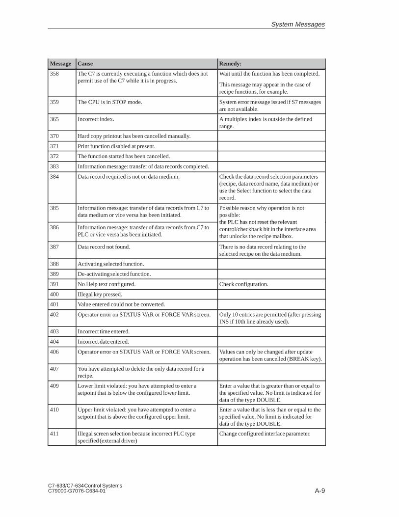
A-9C7-633/C7-634 Control SystemsC79000-G7076-C634-01
Remedy:CauseMessage
358 The C7 is currently executing a function which does notpermit use of the C7 while it is in progress.
Wait until the function has been completed.
This message may appear in the case of recipe functions, for example.
359 The CPU is in STOP mode. System error message issued if S7 messagesare not available.
365 Incorrect index. A multiplex index is outside the definedrange.
370 Hard copy printout has been cancelled manually.
371 Print function disabled at present.
372 The function started has been cancelled.
383 Information message: transfer of data records completed.
384 Data record required is not on data medium. Check the data record selection parameters(recipe, data record name, data medium) oruse the Select function to select the data record.
385 Information message: transfer of data records from C7 todata medium or vice versa has been initiated.
Possible reason why operation is not possible: the PLC has not reset the relevant
386 Information message: transfer of data records from C7 toPLC or vice versa has been initiated.
the PLC has not reset the relevantcontrol/checkback bit in the interface areathat unlocks the recipe mailbox.
387 Data record not found. There is no data record relating to the selected recipe on the data medium.
388 Activating selected function.
389 De-activating selected function.
391 No Help text configured. Check configuration.
400 Illegal key pressed.
401 Value entered could not be converted.
402 Operator error on STATUS VAR or FORCE VAR screen.Only 10 entries are permitted (after pressingINS if 10th line already used).
403 Incorrect time entered.
404 Incorrect date entered.
406 Operator error on STATUS VAR or FORCE VAR screen.Values can only be changed after update operation has been cancelled (BREAK key).
407 You have attempted to delete the only data record for arecipe.
409 Lower limit violated: you have attempted to enter a setpoint that is below the configured lower limit.
Enter a value that is greater than or equal tothe specified value. No limit is indicated fordata of the type DOUBLE.
410 Upper limit violated: you have attempted to enter a setpoint that is above the configured upper limit.
Enter a value that is less than or equal to thespecified value. No limit is indicated fordata of the type DOUBLE.
411 Illegal screen selection because incorrect PLC type specified (external driver)
Change configured interface parameter.
System Messages

A-10C7-633/C7-634 Control Systems
C79000-G7076-C634-01
Remedy:CauseMessage
442 Data block error x DB no. yThis message indicates a data block error. The variables xand y identify the cause of the fault (x) and the number ofthe receive block concerned (y).
Variable x:0 Incorrect block length entered in receive block no. y1 Incorrect block number entered in receive block no. y
Correct the block length/block number asnecessary or send the correct data block.
450 When entering a value, you have attempted to press a keythat is not compatible with the defined input field.
451 You have entered a setpoint that is below the configuredlower limit.
Enter a value that is greater than or equal tothe limit.
452 You have entered a setpoint that is above the configuredupper limit.
Enter a value that is less than or equal to thelimit.
453 Time not entered correctly. Enter time correctly.
454 Interface parameters incorrectly set, e.g. when specifyingparameters for printer interface
Enter valid value for interface parameters.
The following values are valid:
– Transmission rate: 300, 600, 1200,2400, 4800, 9600, 19200 bps
– Data bits: 5,6,7,8
– Stop bits: 1,2
– Timeout: 1...600
455 You have set graphics printing on the C7 but the corresponding ESC sequence has not been configured.
Select a different printer or check printerconfiguration in ProTool.
456 You have entered an incorrect value, e.g. a variable with auser function that blocks certain input values.
Enter permissible value.
458 You have entered a value that is too great or too small forthe variable type concerned, e.g. a value greater than32767 for a variable of the type Integer.
Enter a value that is within the permissiblerange.
459 You are attempting to enter an illegal character (e.g. letterin a numerical value) The input is rejected and the existingentry retained.
Enter permissible value.
500...503 Cyclic interrupt, counter, date or time data can not be sent.This error can occur if the PLC is il l d d if h f i504 Free ASCII protocol: operator input value could not be
sent.
temporarily overloaded or if the functionblock is not called for more than 1.5 s.
505 The data record can not be sent as the recipe disable bit onthe PLC is set or because transfer of a recipe is still inprogress.
Try sending again later when the PLC hasreleased the recipe mailbox.
506 Overload: too many message blocks with the same blocknumber in transit.
This error occurs if the PLC sends too manyjobs using ’collect message area’ within acertain period of time.
507 Transfer of the data record was not acknowledged by thePLC within a certain period.
Checking of data records by the user at thePLC end must be carried out more quickly(< 10 s).
509 Firmware version is different from standard FB version. Please contact the SIMATIC Hotline.
510 Data record not present. A process link with a non-existent datablock has been configured in a recipe or therecipe data contain errors.
System Messages

A-11C7-633/C7-634 Control SystemsC79000-G7076-C634-01
Remedy:CauseMessage
511 You have used a PLC job to select a recipe or a requestdata record that does not exist.
512 Configured data block length is too short.
The variable transferred with the message identifies thenumber of the data block.
Change configuration and retransfer.
516 SINEC L2 protocol configured but no interfacesubmodule inserted.
Change configuration and retransfer.
518 Interface submodule inserted and protocol configured donot match.
Change configuration and retransfer.
520 Excessive number of saved returns has meant that maximum nesting level has been exceeded.
Go to Message Level (by pressing ESC keyif necessary).
521, 522 Screen can not be constructed or selected because there isnot enough memory available.
Message 522 triggers a restart with memory optimization.
You can optimize memory availability by
1. Removing unused fields from the configuration.
2. Configuring the screen with fewerfields, or splitting it into more than onescreen.
3. Creating fewer recipe data records.
523 No text found.
524 Object class does not exist.
525 Illegal address.
526 Loop-through operation is set on the C7. Change mode from “Loop-through operation” to “Normal operation”.
527 Access to recipe data is not possible at present.
528 Recipe does not exist.
529 File does not exist.
530 Data record not present.
531 Data record can not be loaded.
532 Information message: data record memory is full.
533 Floppy connection unclear.
534 Information message: disk is full.
535 Disk access error.
536 Disk transfer error. Check the physical connection.
537 Information message: disk is blank.
538 Simultaneous accessing of data record by job and operator.Repeat uncompleted accessing operation.
539 The data records in the RAM for recipe no. x containederrors and have been deleted.
If data records are stored in the Flashmemory they will remain valid.
540 The maximum number of data records has already beencreated.
541 ...550
Specified variable not available on PLC. Change configuration and retransfer.
551 An MPI/PPI connection to the PLC cannot be establishedusing the specified station address.
Check MPI station addresses and wiring.
System Messages

A-12C7-633/C7-634 Control Systems
C79000-G7076-C634-01
Remedy:CauseMessage
552 Query: safety check as to whether the selected data recordis to be deleted. The data record is only deleted if 0 is entered. If not the function is cancelled.
This query is also used when backing up orrestoring configurations. In that case, it relates to deletion of all data records in thesystem memory.
553 Information message: selected data record has been deleted.
554 Query: 1st safety check as to whether the data medium forstoring data records is to be formatted. Any data recordsalready on the disk will be deleted when the function isexecuted! The function is only executed if 0 is entered.
555 Query: 2nd safety check as to whether the data medium forstoring data records is to be formatted. Any data recordsalready on the disk will be deleted when the function isexecuted! The function is only executed if 0 is entered.
556 Information message: disk has been formatted.
557 Query: if 0 is entered the data record will be adopted withthe new values. If anything else is entered, you may continue editing.
558 Query: if 0 is entered the edited data record is rejected. Thedata remain as they were before editing. If anything else isentered, you may continue editing.
559 Query as to whether the event message buffer should becleared.
560 Query as to whether the alarm message buffer should becleared.
561 Information message: appears if a global data record (V3.0or later) is edited and not all entries that are defined in thecurrent recipe are completed. The data record can only besaved if the marked entries are edited. If no entries aremarked, only the version number has changed.
Only returned in the case of data recordsthat are transferable from one recipe toanother. Missing entries are marked andmust be edited. Editing can, however, becancelled at any time.
562 Information as to which mode was set using the function“First/Last Message”.
563 Information as to which mode was set using the function“First/Last Message”.
564 Query: if 0 is entered the data record is created. If anythingelse is entered, the function is cancelled.
565 Query: if during transfer of a global data record it is foundthat not all entries are present, the missing entries can be
– read by the PLC if 1 is entered, or
– edited if 2 is entered
If 3 is entered, transfer is cancelled.
Only returned in the case of data recordsthat are transferable from one recipe toanother. (V3.0 or later, plastic functions.)
566 Data record contains array that does not fit the currentrecipe structure.
The following question appears:
Save yes/no? .
If you elect to save, the array data are set to0.
System Messages

A-13C7-633/C7-634 Control SystemsC79000-G7076-C634-01
Remedy:CauseMessage
567, 568 If the message buffer has to be cleared, pendingevent/alarm messages also have to be deleted in order tomake space for new message events.
Check configuration. Too many messagesare pending.
569 Fault on CPI submodule. – CPI no.: defective CPI submodule
– Error:
1 = Voltage too low
2 = Current too high
3 = Temperature too high
4 = Module not present (failed duringoperation)
570 Variable contains errors: variable name from ProTool isused as parameter.
Check configuration. Frequently occurswith NC variables and when multiplexing.
571 S7 system diagnosis/INTERRUPT_S returns error if C7logs on/off.
CPU operating system out of date.
572 Query: data record already exists on data medium. If 0 is entered the data record will be overwritten with the new values.
600 Configuration error: overflow warning at basic setting 1
601 Configuration error: message logging at basic setting 1
602 Configuration of remaining buffer space incorrect. Correct the remaining buffer space andretransfer configuration.
604 Message does not exist. Configure message.
605 Process link is only configured symbolically. Change configuration and retransfer.
606 Too many message variables configured.
g g
607 Data type configured does not exist.
608 The process screen number does not exist.
609 Special object or operator object for message text does notexist or is not permissible.
610 Operator object for header or footer does not exist or is notpermissible.
If the fault is not corrected by performing arestart, please contact the SIMATIC Hotline.
611 Special operator object for buffer printout does not exist oris not permissible.
, p
613 Data block not available or too short. Create data block of required length on thePLC.
614 No entry present for log (header and footer not present).Configure log fully.
615 The line to be output is larger than the amount of printmemory reserved for it or the number of control sequencesis too great.
Check configuration as regards logging.
616 Internal error
Incorrect data format in process link.
Correct the data format.
617 Internal error
Incorrect word length in process link.
Correct the word length.
618 Configuration error in actual control value (bit number >15).
Bit number for actual control variable mustbe < 15.
619 Error presetting setpoint (error in data structures). Change configuration and retransfer.
System Messages

A-14C7-633/C7-634 Control Systems
C79000-G7076-C634-01
Remedy:CauseMessage
620 Illegal keyboard ID: submodule number too high ornumber of keys does not match keyboard ID.
Enter configuration to match hardware.
621 Incorrect parameter transferred: message type Set required value by way of standardscreen or PLC.
622 Configured recipe does not fit in recipe mailbox on PLC(> 512 data words).
Reduce configured size of recipe andretransfer configuration.
623 Internal error
Screen object for “Send Recipe“ is not a recipe type (fixedby COM TEXT).
If the fault is not corrected by performing arestart, please contact the SIMATIC Hotline.
624 No recipe entries found. Set up area pointers and retransferconfiguration.
625 Recipe number does not exist. Reconfigure recipe.
626 No setpoints have been configured.
g p
627 Internal error
Configured keyboard block number too high.
Correct the block number.
628 Recipe does not fit in mailboxes. Increase configured size of recipe mailboxor succeeding recipe mailbox.
629 LED image area too small. Increase size of LED image area accordingto bit numbers used.
630 Keyboard image area too small. Increase size of keyboard image areaaccording to bit numbers used.
631 Message configuration incomplete or incorrect.
Variable x:1, 2 Alarm message triggered not configured.3 Process link only created symbolically.4 Actual value field only created symbolically.5, 6 Event message triggered not configured.7 Symbolic actual value field only created
symbolically.21..24 Field texts for symbolic actual value do not exist.25 Illegal field type.8..20 Internal error.
Complete configuration. If the fault is not corrected by performing arestart, please contact the SIMATIC Hotline.
632 Configuration error:
Variable x:1, 4 Information text does not exist2 Information text ID for messages does not exist3, 6..8, Internal error11, 135 Field only created symbolically9 Screen or recipe entry only created symbolically12 Process screen or recipe contains no entries
Check the configuration. If the fault is notcorrected by performing a restart, pleasecontact the SIMATIC Hotline.
634 Configuration error:
Variable x:0..8, 34 Internal error18 Screen or recipe title not configured
Screen or recipe title not configured. If thefault is not corrected by performing a restart,please contact the SIMATIC Hotline.
System Messages

A-15C7-633/C7-634 Control SystemsC79000-G7076-C634-01
Remedy:CauseMessage
635 Configuration error:
Variable x:1 Screen or recipe entry only created symbolically.3 Field only created symbolically.6 Message, entry or information text not configured
for current language.7...9, Internal error. 19, 28,41...4318 Screen or recipe title not configured.20 Process link only created symbolically.21 Information text only created symbolically.22 Symbolic field only created symbolically.23 Fewer than 2 field texts configured for symbolic
field.24 Current field type for symbolic field not
configured.25 Illegal data format for symbolic field (only KF and
KY permissible).26 Recipe setpoint configured with data format KC.33 Illegal data format for setpoint field.35 Data format for cyclic interrupt too short.36 Illegal data format for actual control value.44 If specific reference to menu: menu item not
present.45 If specific reference to screen: Entry or field
number does not exist.46 Too many actual control values on screen
(max. 200 permitted).48 Too many fields on process screen.50 Process link for soft keys does not exist.51 Soft key number too high.53 Information text for soft key not configured or not
configured in all languages.55 Soft key specified in entry does not exist.
Check the configuration. If the fault is notcorrected by performing a restart, pleasecontact the SIMATIC Hotline.
636 Event message is not configured Configure event message (–> messageb ) f ll
637 Missing configuration for an event message
g g ( gnumber) fully.
638, 639 Actual value field for event message has only been createdsymbolically.
640 Alarm message is not configured Configure alarm message (–> message
641 Alarm message triggered is not configured
g g ( gnumber) concerned.
642, 643 The actual value field for alarm message has only beencreated symbolically.
Reconfigure interrupt message (–> messagenumber).
645 Internal error
PLC co-ordination area is not receivable during startup.
Press key to restart. If the fault is notcorrected by performing a restart, pleasecontact the SIMATIC Hotline.
648 The driver number configured cannot be interpreted.
649 Internal error
Driver number configured cannot be interpreted.
If the fault is not corrected by performing arestart, please contact the SIMATIC Hotline.
650 Missing area pointer. Configure an area pointer.
System Messages

A-16C7-633/C7-634 Control Systems
C79000-G7076-C634-01
Remedy:CauseMessage
651 Internal error
There is not at least one data record for every recipe.
If the fault is not corrected by performing arestart, please contact the SIMATIC Hotline.
652 Configuration is not compatible with S5. Change configuration and retransfer. If thefault is not corrected by performing a restart,please contact the SIMATIC Hotline.
653 The configured user version number does not match theversion number stored on the PLC.
Change configuration and retransfer.
654 The PLC acknowledgement area has not been configuredto follow on physically from the message area.
655 PLC acknowledgement area does not physically follow onfrom the alarm message area (–> no startup).
656 Configured protocol is not possible. Check protocol in configuration.
657 Configured PLC protocol is not possible. Use current firmware version or configuredifferent protocol.
658 Configured PLC protocol is not possible.
659 Illegal process link in recipe, destination does not exist. Change configuration and retransfer.
660 Invalid destination configured for return reference inmenu.
Break key on C7; complete configurationand retransfer
661 On process screen: recipe setpoint or previous value configured in recipe: field is neither recipe setpoint or previous value.
Change field type or remove field and retransfer configuration
662 Invalid destination configured for return reference inscreen.
Change configuration and retransfer.
663 Data record memory full (during startup)
664 Standard data records for the configured recipes requiremore than 20 Kbytes. Unit switches to COM TEXT mode.
Configure fewer or smaller recipes.
665 Configuration of interfaces incorrect, printer/PLC interfaces have same physical characteristics.
Check interface parameters.
667 Configuration error:
Variable x:1 Data type is not DB2 DB number is greater than 153 DB length is greater than 10244 DW is in data block header5 Actual value not in send block6 Setpoint not in receive block7 Setpoint/actual value not in receive block8 Initial value not in send block9 Data type is not DB10 DB number is greater than 1511 DB length is greater than 102412 DW is in data block header13 Area is in wrong DB14 Sum of data blocks too great
x = 1..8: Change the configuration of theprocess link and retransfer.
x = 9..13:Change configuration of areapointer and retransfer.
x = 14: Restrict configuration and retransfer.
System Messages

A-17C7-633/C7-634 Control SystemsC79000-G7076-C634-01
Remedy:CauseMessage
668 Incorrect configuration.
Meaning of variables:
1: Incompatible PLC types configured.
2: No PLC configured.
3: Incorrect transmission rate configured.
Change configuration and retransfer.
669 Too many actual values (> 512) have been configured forcyclic reading in a screen/variable.
670 Too many variables requested simultaneously. Lengthen standard clock pulse or configurefewer variables on screen.
671 Configuration of message variables incompatible. Differences between configuration and PLC.
Check S7 programs.
Check message server configuration.
672 Message not configured.
Check message server configuration.
Change configuration and retransfer.
681 Overload caused by too many variables (setpoints/actualvalues).
Fault in connection between the C7 and PLC.
Check the interface parameters.
682 Incorrect interface parameters configured. Configure fewer process links for the screendisplayed.
683 Configuration error:
upper limit = lower limit
Correct the limits and retransfer configuration.
684 Non-existent trend switch buffer requested. Check PLC program/C7 configuration.
Only use trend request area 2 for trends withswitch buffer.
685 Illegal job issued to send task for parallel interface.
701 Internal error
Incorrect assignment of “head –> res“ when receivingvariable.
702 Job can not be executed. Change interface or configure area pointer.
703 Flash memory full. Restrict the configuration.
704 Incorrect CPU specified under the menu command“System,” “Parameters” button in the dialog box whichappears.
Change configuration and retransfer.
705 An acknowledged message cannot be entered in the bufferbecause the corresponding message or a message in thesame acknowledgement group is missing.
706 Recipe request will not be processed as another request isalready active.
707 Internal error
S7 message task error.
708 Internal error
Incorrect mailbox type.
System Messages

A-18C7-633/C7-634 Control Systems
C79000-G7076-C634-01
Remedy:CauseMessage
709 Internal error
Invalid mailbox type.
710 Internal error
Incorrect operating mode.
711 Internal error
Display status invalid.
712 No submenu configured.
713 Internal error
No special operator object configured.
714 Internal error
Menu number invalid.
715 Internal error
Mailbox type of received message is incorrect.
716 Internal error
The setting for the maximum number of messages is toohigh (variable overflow).
717 Internal error
Incorrect message status when entering in statistics.
718 Internal error
Incorrect message status when entering in event messagebuffer.
719 Internal error
Incorrect message status when entering in alarm messagebuffer.
720 Internal error
Error reading messages from message buffer.
721 Internal error
Configuration message error.
722 Internal error
Incorrect mailbox type received (OP15 –> OP5)
723 Internal error
OP5: more than 500 messages are specified in the areapointer lists.
Change area pointer list.
724 Internal error
Mailbox type not implemented.
725 Internal error
Block number does not exist.
726 Internal error
Incorrect mailbox type.
System Messages

A-19C7-633/C7-634 Control SystemsC79000-G7076-C634-01
Remedy:CauseMessage
727 Internal error
Illegal screen type.
728 Internal error
Return reference number incorrect.
729 Internal error
Error in internal mailbox buffer management for directmessage logging.
731 Internal error
Transfer parameter LEDSTATUS is incorrect in RIO function “Change LED Status”.
732 Internal error
Key number can not be higher than 7/15/23(8-key/16-key/24-key keyboard).
733 Internal error
Key number must be less than 4 as a maximum of 4 keysis possible.
734 Internal error
The submodule number must be 0.
735 Internal error
Illegal RIO function.
The following are permissible: Read, Write(LEDs, outputs) and Initialize.
736 Internal error
Keyboard driver error.
737 Internal error
Too many keyboard image areas (mailboxes) beingtransferred to PLC.
738 Internal error
Mailbox type of received message is incorrect.
739 Internal error
Key acknowledgement received when message alreadyacknowledged.
740 Internal error
Message status not permitted for first alarm/event message.
741 Internal error
Buffer type different from event or alarm message buffer.
742 Internal error
Message type different from event or alarm messagebuffer.
743 Internal error
Configuration message error.
System Messages

A-20C7-633/C7-634 Control Systems
C79000-G7076-C634-01
Remedy:CauseMessage
744 Internal error
Incorrect mailbox type received.
746 Internal error
Actual control value and process link are identical on ascreen.
In COM TEXT: change address.
747 Internal error
Buffer type different from event or alarm message buffer.
748 Internal error
Message type different from event or alarm messagebuffer.
749 Internal error
Error in data structure of a buffer function screen.
750 Internal error
Error in data structure of the password function screen.
751 Internal error
Error in data structure of screen for setting time.
752 Internal error
Error in data structure of the Login screen.
753 Internal error
Error in data structure of other type of function screen.
In COM TEXT: IHV recipes affected.
754 Internal error
Error in data structure of “Average Statistics” screen.
759 Internal error
Error group (task ID) does not exist.
760 Internal error
The message number for this error group does not exist.
761 Internal error
Communication: mailbox type of received message is incorrect.
762 Internal error
Configuration error: message for which there is no textexpected. 761 received instead.
Occurs if, for example, new firmware is being used with old COM TEXT version.
763 Internal error
Configuration error.
764, 765 Internal error
There are two variables:
Var.1: for the message number, Var.2: a number for theerror location
System Messages

A-21C7-633/C7-634 Control SystemsC79000-G7076-C634-01
Remedy:CauseMessage
767, 769,771
Internal error
With stop, TD10 - TD/OP20 different.
772 Internal error
Communication error (–> Message frames).
774 Internal error
Error reading area pointer.
776 Internal error
Data record memory full.
777 Internal error
Too many cyclic interrupts in transit.
780 Internal error
Internal error during MPI download; possibly due tobuffer problems.
Reset and repeat MPI download.
781 Internal error
Undefined error from communication with PLC.
782 An “Online Setter” function has been incorrectly definedin ProTool.
System Messages

A-22C7-633/C7-634 Control Systems
C79000-G7076-C634-01
System Messages

B-1C7-633/C7-634 Control SystemsC79000-G7076-C634-01
Technical Specifications for the C7
This chapter lists the technical specifications of the C7.
These technical specifications include the standards and test values that theC7 conforms to or the criteria against which the C7 has been tested.
Section Description Page
B.1 Technical Specifications B-2
B.2 Notes on the CE Marking B-11
B.3 Notes for Machine Manufacturers B-12
B.4 Transport and Storage Conditions for Backup Batteries B-13
What are theTechnicalSpecifications?
ChapterOverview
B

B-2C7-633/C7-634 Control Systems
C79000-G7076-C634-01
B.1 Technical Specifications
General TechnicalSpecifications
C7-633 DP C7-634 DP C7-633 P C7-634 P
Order number 6ES7633-2BF00-0AE3 6ES7634-2BF00-0AE3 6ES7633-1DF00-0AE3 6ES7634-1DF00-0AE3
Dimensions• Device (B x H x D)• Cutout (B x H)
240 x 203.5 x 74.4 mm231 x 159 mm
240 x 203.5 x 89.4 mm231 x 159 mm
Weight 1600 g 1700 g 1800 g 1900 g
Safety of electrical equipment• Standards• Protection against foreign
particles and water
EN 61131-2 according to IEC 1131-2Front: IP 65 according to IEC 529Housing: IP 20 according to IEC 529
• Fire safety According to UL 94
Plug connectors V2
Basic connectors in housingHousing/front
V0
V0
Acceptance tests, certification EN 61131-2 (IEC 1131-2)UL Listing UL 508Canadian Standard Association (CSA) acc. to Standard C22.2 Number 142FM approval, FM standards No. 3611, 3600, 3810 Class I, Div. 2 Group A, B, C, DISO 9001 certification of manufacture and development
Operational ambient temperature• when mounted vertically
through 455• when mounted horizontally
through 455
tested to IEC 68-2-1, IEC 68-2-2
±0 to +50°C
±0 to +45°C
• storage/transport -20°C to +70°C
Relative humidity• operation• storage/transport
tested to IEC 68-2-35 to 95 % at 25°C (no moisture condensation)5 to 95 % at 25°C (no moisture condensation)
Air pressure• operation• storage/transport
795-1080 hPa (corresponds to -1000 m to +2000 m)660-1080 hPa (corresponds to -1000 m to +3500 m)
Isolation --- yes, digital inputs/outputs, analog inputs/outputs (not for universal inputs)500 V DC
Supply voltage• rated voltage (VN)• permissible range
Safety extra-low voltage, SELV24 VDC20.4 VDC to 30.2 VDCNote:The C7 has no integrated protection against high-energy glitches in ms range (surges).
• polarized input voltage• open circuit
(can be jumpered)
yes
≥ 20 ms
• current consumption (IN)typ. / max.
• power loss550 mA / 1A12 W
Electromagnetic compatibility(EMC)• Limit class for emitted
interferenceClass B to EN55022 (corresponds to CISPR 22)
Technical Specifications for the C7

B-3C7-633/C7-634 Control SystemsC79000-G7076-C634-01
C7-634 PC7-633 PC7-634 DPC7-633 DPGeneral TechnicalSpecifications
• Conducted interference onvoltage supply lines
±2kV to IEC 1000-4-4; burst±1kV to IEC 1000-4-5; µs-pulse / line to line *)±2kV to IEC 1000-4-5; µs-pulse / line to ground *)*) with protection element lightning conductor KT Type 24 VAD from “Dehn” firm
• Immunity to interference onsignal lines
±2kV at IEC 1000-4-4; burst
• Immunity to discharge +6kV, contact discharge, to IEC 1000-4-2; ESD+ 8 kV, air discharge, to IEC 1000-4-2; ESD
• Immunity to high-frequency radiation
10V with 80% amplitude modulation with 1KHz10KHz to 80MHz, to IEC 1000-4-6
10V/m with 80% amplitude modulation with 1KHz80KHz to 80MHz, to IEC 1000-4-3
10V/m pulse-modulated 50% ED with 900MHz, to EN 50140
Mechanical loading• Vibration
tested to IEC 68-2-6
Tested with 10 to 58 Hz; amplitude 0.075 mm58 to 500 Hz; acceleration 9.8 m/s2
Storage/transport 5 to 9 Hz; amplitude 3.5 mm9 to 500 Hz; acceleration 9.8 m/s2
• Shock tested to IEC 68-2-29
Tested with semi-sinusoidal: 100 m/s2 (10 g), 16 ms; 100 shocks
Storage/transport semi-sinusoidal: 250 m/s2 (25 g), 6 ms; 1000 shocks
Backup battery Backup time approx. 1 year
Communication C7-633 DP C7-634 DP C7-633 P C7-634 P
Communication functions• PG/OP communication• Global data
communication• Basic communication• Expanded communication• S5-compatible
communication• Standard communicationNumber of connectionsstatic/dynamic
yesyes
yesyes (Server)yes
yes
4/8
Multipoint interface MPI yes, 2 nodes occupied per device (1x CPU, 1x OP)
• No. of nodes max. 32 nodes; programming device/PC, OP, S7-300;per node max. 4 active connections to programming device/PC or OP
• Transfer rate max.• Distance between 2
neighboring nodes187.5 Kbpswithout repeaters: 50 mwith 2 repeaters: 1100 mwith 10 repeaters in series: 9100 mvia fiber-optic cables: 23.8 km (with star coupler or OLM)
• Connectable programming devices
PG 720/720C, PG 740, PG 760, PC (AT) with MPI connection
• Guaranteed connections 1 for connection of programming device1 for connection of operator panel8 for program-controlled communication
• Free connections 2 for free programming device/OP program-controlled communication
Technical Specifications for the C7

B-4C7-633/C7-634 Control Systems
C79000-G7076-C634-01
Communication C7-633 DP C7-634 DP C7-633 P C7-634 P
PROFIBUS DP interface
Integrated / external 1 / CP342-5 (via IM expansion) --- / CP342-5 (via IM expansion)
• Transfer procedure PROFIBUS DP to DIN 19245 Part 3DP master / slave
• Transmission rate 12 Mbps
• Number of DP stations permaster (integrated or external interface)
64
• Address area per DP station122 bytes inputs and 122 bytes outputs, configurable in up to 32 address areas, max. 32 bytesper address area
• Modules per ET200M 8
• Master or slave yes
Programming, Planning,Configuration
C7-633 DP C7-634 DP C7-633 P C7-634 P
Programming, Configuration(PLC)• Programming software• Programming languages
STEP 7, STEP 7 MiniSTL, LAD, other languages optional
HMI configuration ProTool, ProTool/Lite
Programmable Controller C7-633 DP C7-634 DP C7-633 P C7-634 P
Main memory (1 instruction cor-responds to approx. 3 bytes)
64 Kbytes / 20 K instruction RAM 48 Kbytes / 16 K instruction RAM
Load memory• Integrated• External max.
96 Kbytes RAM512 Kbytes FEPROM (memory card)
Data backup with battery
without batteryall datamax. 4736 bytes, can be configured for bit memory, timers, counters, data (max. 8 DBs, max.4096 data bytes retentive in total)
Programming organization linear, structured
User program protection • Knowhow-protect• Password protection
Instruction set Binary logic, bracketed commands, result assignment, save, count, load, transfer, compare,shift, rotate, generate complement, call blocks, integer math instructions, floating-point mathinstructions, jump functions
Types of blocks • Organization blocks (OB)• Function blocks (FB)• Functions (FC)• Data blocks (DB)• System functions (SFC)• System function blocks (SFB)
No. of blocks max. 128 FCs, 128 FBs, or 127 DBs
Program processing • Startup (OB100)• Free cycle (OB1)• Real-time controlled (OB10)• Time-driven (OB35)• Interrupt-driven (OB40)• Error handling (OB80, 81, 82, 85, 86, 87,
121, 122)
• As C7-633/634 DP, but without errorhandling OB86
Technical Specifications for the C7

B-5C7-633/C7-634 Control SystemsC79000-G7076-C634-01
C7-634 PC7-633 PC7-634 DPC7-633 DPProgrammable Controller
System functions (SFC) Masking of interrupts, copying of data, real-time clock functions, diagnostic functions, errorhandling, module parameter assignment
Block nesting depth 8 for each program execution level
Bracket levels 8
Execution times for• Bit operations• Word operations• Time/counter operations• Fixed-point addition• Floating-point addition
0.3 µs (0.3 ms per 1000 binary instructions)1 µs12 µs2 µs50 µs
Cycle-time monitoring 150 ms (preset),selectable 1 to 6000 ms
Bit memories• Retentive with battery
• Retentive without battery
• Clock memory
20480 to 2047
0 to 2047, selectable
8 (1 memory byte),freely selectable address of a memory byte (clock memory that can be used in the user program)
Counters• Retentive with battery
• Retentive without battery
• Counting range
640 to 63
0 to 63, selectable
1 to 999
Timers (are only updated inOB1)• Retentive with battery
• Retentive without battery
• Counting range
128
0 to 127
0 to 127, selectable
10 ms to 9990 s
Process image• Digital inputs• Digital outputs
0 to 127I0.0 to Q127.7Q0.0 to Q127.7
On-board interface module IM 360
Expansion with S7-300 modulesmax. 3-tier
S7-300 expansion modules max. 24
I/O expansions• Digital inputs/outputs max.• Analog inputs/outputs
max.
768
192
Operable modulesFMCP, point-to-pointCP, LAN
842
Clock Real-time clock (hardware clock)
Run-time meter• Value range• Granularity• Retentive
0 to 32767 hours1 houryes
Technical Specifications for the C7

B-6C7-633/C7-634 Control Systems
C79000-G7076-C634-01
Human-machine interface(HMI)
C7-633 DP C7-634 DP C7-633 P C7-634 P
Built-in configuration memory 128 Kbyte Flash 256 Kbyte Flash 128 Kbyte Flash 256 Kbyte Flash
Display STN LC display, LED backlighting
• Operating life of backlighting
approx. 100,000 h (approx. 11 years)
• Number of lines x characters per line
• Line height
4 x 20
8 mm
4 x 20 / 8 x 40 selectable11 mm / 6 mm
4 x 20
8 mm
4 x 20 / 8 x 40 selectable11 mm / 6 mm
Keyboard• Softkeys• Function keys
Function keys that can beconfigured as softkeys
• System keys• Number of LEDs / of which
two-color LEDs
Membrane keyboard416
62432 / 16
Membrane keyboard816
82432 / 16
Membrane keyboard416
62432 / 16
Membrane keyboard816
82432 / 16
Event messages max.499 999 499 999
• Event message buffer max. 256 entries
• Page event messages max. 256
Alarm messages 499 999 499 999
• Alarm message buffer max. 256 entries
No. of variables in message textmax. 8
No. of displays 99
Entries per display 99
Recipes max. 99
• Recipe data memory 4 Kbytes 20 Kbytes 4 Kbytes 20 Kbytes
• Data records per recipe max. 99
• Entries per data record max. 99
Semi-graphics According to character set
Symbols/character sets 1
Dynamic objects Input, output, I/O fields, date/time fields, symbolic I/O fields
Online languages 3
Password levels 9
Clock Software clock Hardware clock Software clock Hardware clock
Load/printer interface RS 232 / TTY
Built-in inputs/outputs C7-633 DP C7-634 DP C7-633 P C7-634 P
Built-in digital inputs - 16
Input voltage• Rated value• With signal “1”• With signal “0”
24 V DC11 to 30 V-3 to 5 V
Isolation Yes, via optocouplers in groups of 16
Input delaytyp./max. 3/4.8 ms
Input current with signal “1”max. 11.5 mA
Technical Specifications for the C7

B-7C7-633/C7-634 Control SystemsC79000-G7076-C634-01
C7-634 PC7-633 PC7-634 DPC7-633 DPBuilt-in inputs/outputs
Connecting 2-wire Beros• Permissible closed-circuit
current max.2 mA
Cable lengths• Unshielded• Shielded
600 m1000 m
Built-in digital outputs - 16
Load rated voltage• permissible range
24 V DC20.4 to 28.8 V
Output voltage• with signal “1” max. L + (-0.8 V)
Isolation Yes, via optocouplers, two groups of 8
Output current• with signal ”1” rated value
minimum current• with signal ”0” max.
0.5 A5 mA0.5 mA
Cumulative current per group of8
• at 20 °C• at 50 °C
4 A2 A
Lamp load max. 5 W
Switching frequency• under impedance load• under inductive load
100 Hz0.5 Hz
Limiting of voltage induced oncircuit interruption to L + (-48 V)
Short-circuit protection Yes, electronically clocked
Cable lengths• Unshielded• Shielded
600 m1000 m
Built-in universal inputs - 4
Can be used asUI1 Digital/interrupt input 24 V DC
or up/down counter orexternal gate counter
UI2 Digital/interrupt input 24 V DCor up/down counter orexternal gate counter
UI3 Digital/interrupt input 24 V DCor up/down counter or frequency/period duration counter orexternal gate counter
UI4 Digital/interrupt input 24 V DC
Isolation No
Input voltage• Rated value• With signal ”1”• With signal ”0”
24 V DC11 to 30 V-3 to 5 V
Input current with signal “1”typ. 2 to 8 mA
Cable lengths• Unshielded• Shielded
600 m1000 m
Technical Specifications for the C7

B-8C7-633/C7-634 Control Systems
C79000-G7076-C634-01
C7-634 PC7-633 PC7-634 DPC7-633 DPBuilt-in inputs/outputs
Counter frequency max. 10 kHz
Counters max.• Principle• Count range C1/C2
• Count range C3
• Limit value (nominal)default
• Count interrupt up counter• Count interrupt
down counter• Enable
3Edge counting
up: 0 to 65535down: 65535 to 0up: 0 to 16777215down: 16777215 bis 0
1 value per counter
On reaching the limit valueOn reaching “0”
Within the program
Period duration counter max.• Principle
• Count range• Period duration max.
1Counting fixed time units between two positive edges0 to 167772158.388 s or 0.119 Hz
Frequency counter max.• Principle
• Count range• Gate width
1Counting pulses within a timer period
0 to 167772150.1 s; 1 s; 10 s (selectable)
External gate counter max.• Principle
• Count range C1/C2• Count range C3
3Counting edges within a gate time viaexternal pin0 to 216-10 to 224-1
Built-in analog inputs - 4
Input range (selectable) / inputresistance
10V/50 kΩ 20 mA/105.5 Ω, 4 to 20 mA/105.5 Ω
Permissible input voltage forvoltage input max. 30 V
Permissible input current forcurrent input max. 30 mA
Isolation Yes, shared with A0
Cycle time (all channels) 2 ms
Conversion time per channel 0.5 ms
Resolution 12 bits incl. sign
Operational limit (over entiretemperature range, withreference to input range)• Voltage• Current
0.8 % 0.8 %
Basic error limit (operationallimit at 25 °C, with reference toinput range)• Voltage• Current
0.6 % 0.6 %
Technical Specifications for the C7

B-9C7-633/C7-634 Control SystemsC79000-G7076-C634-01
C7-634 PC7-633 PC7-634 DPC7-633 DPBuilt-in inputs/outputs
Interrupts• Hardware interrupts
As cyclic interruptAs end-of-cycle interrupt
• Diagnostic interrupt
• Interrupt cycle
Yes, configurableYes, configurableOverranging, open-circuit detection at 4 to 20mA with softwareYes, configurable
Cable length, shielded max. 200 m
Built-in analog outputs - 4
Output range• Voltage output• Current output
10 V 20 mA
Load impedance• For voltage outputs min.• For current outputs max.• For capacitative load max.• For inductive load max.
2 kΩ0.5 kΩ1 µF1 mH
Voltage output• Short-circuit protection• Short-circuit current
Yes25 mA
Current output• No-load voltage max. 15 V
Isolation Yes, shared with AI
Resolution 12 bits incl. sign
Cycle time (all channels) Type 2 ms max. 4 ms
Transient recovery time• For resistive load max.• For capacitative load max.• For inductive load max.
0.1 ms3.3 ms0.5 ms
Applicable substitute values Yes, configurable
Operational limit (0 to 60 °C,with reference to output range)• Voltage• Current 0.8 %
1 %
Basic error limit (operationallimit at 25 °C, withreference to output range)• Voltage• Current
0.5 % 0.6 %
Interrupts• Diagnostic interrupt Yes, configurable
for parameter error
Cable length, shielded max. 200 m
Technical Specifications for the C7

B-10C7-633/C7-634 Control Systems
C79000-G7076-C634-01
The whole 24-VDC power supply for the C7 (operating voltage, load voltage,relay power supply etc.) must be provided in the form of safety extra-lowvoltage (SELV).
!Warning
Personal injury and property damage can occur.
If you do not provide the correct 24-VDC power supply for your C7, thismay result in damage to components of your programmable controller orinjury to personnel.
Use only safety extra-low voltage (SELV) for the 24-VDC power supply toyour C7.
If the device carries any of the following markings, the respective approvalhas been obtained:
Underwriters Laboratories (UL) to UL 508 standard
UL Recognition Mark
Canadian Standard Association (CSA) to standard C 22.2. No 142
FM
APPROVED
FM Standards No. 3611, 3600, 3810 APPROVED for use in Class I, Division 2, Group A, B, C, D indoor hazardous locations.
24-VDC PowerSupply
Important for theUSA and Canada
FM Approval
Technical Specifications for the C7

B-11C7-633/C7-634 Control SystemsC79000-G7076-C634-01
B.2 Notes on the CE Marking
The product meets the requirements of EU Directive 89/336/EEC“Electromagnetic Compatibility.”
In accordance with the above-mentioned EU Directive, Article 10 (1), the EUdeclarations of conformity and the relevant documentation are held at thedisposal of the competent authorities at the address below:
Siemens AktiengesellschaftBereich Automatisierungs- und AntriebstechnikA&D AS E4Postfach 1963D-92209 AmbergFederal Republic of Germany
The C7-633 and C7-634 control systems have been designed for use in thefollowing areas in accordance with their CE marking:
Area of Use RequirementsEmitted interference Immunity
Industrial environmentEN 50081-2: 1993 EN 50082-2: 1995
Residential, commercial, lightindustry
EN 50081-1: 1992 EN 50082-1: 1992
SIMATIC products meet the requirements if you observe the installationguidelines described in the manual when installing and operating theequipment.
EU EMC Directive89/336/EEC
Areas of Use
Observing theInstallationGuidelines
Technical Specifications for the C7

B-12C7-633/C7-634 Control Systems
C79000-G7076-C634-01
B.3 Notes for Machine Manufacturers
The SIMATIC programmable controller is not a machine as defined in the EUMachinery Directive. There is therefore no declaration of conformity forSIMATIC with regard to the EU Machinery Directive 89/392/EEC.
The EU Machinery Directive 89/392/EEC regulates requirements relating tomachinery. A machine is defined here as an assembly of linked parts orcomponents (see also EN 292-1, paragraph 3.1).
SIMATIC is part of the electrical equipment of a machine and must therefore beincluded by the machine manufacturer in the declaration of conformityprocedure.
The EN 60204-1 standard (Safety of Machinery, Electrical Equipment ofMachines, Part 1, Specificationfor General Requirements) applies for electricalequipment of machinery.
The table below is designed to help you with the declaration of conformity andto show which criteria apply to SIMATIC according to EN 60204-1 (as of June1993).
EN 60204-1 Subject/Criterion Remarks
Paragraph 4 General requirements Requirements are met if the devicesare mounted/installed in accordancewith the installation guidelines. Observe the explanations on theprevious pages.
Paragraph 11.2 Digital I/O interfaces Requirements are met.
Paragraph 12.3 Programmable equipment Requirements are met if the devicesare installed in locked cabinets forprotection of memory contents againstchange by unauthorized persons.
Paragraph 20.4 Voltage tests Requirements are met.
Introduction
EU MachineryDirective89/392/EEC
ElectricalEquipment ofMachinery inAccordance withEN 60204
Technical Specifications for the C7
B-13C7-633/C7-634 Control SystemsC79000-G7076-C634-01
B.4 Transport and Storage Conditions for Backup Batteries
Transport backup batteries where possible in their original packaging.Observe the regulations for the transport of dangerous goods and substances.The backup battery contains approximately 0.25 g of lithium.
Note: According to air freight transport regulations, the backup battery is inHazardous Goods Class 9.
Store backup batteries in a cool, dry place.
Backup batteries can be stored for up to five years.
!Warning
Backup batteries can ignite or explode and constitute a serious fire hazard ifthey are heated or damaged.
Store batteries in a cool, dry place.
To prevent hazards when using backup batteries, you must observe thefollowing rules:
Do not
Recharge
Heat
Burn
Drill
Crush
Short-circuit
backup batteries.
Transport ofBackup Batteries
Storage of BackupBatteries
Rules for Handlingand Using BackupBatteries
Technical Specifications for the C7

B-14C7-633/C7-634 Control Systems
C79000-G7076-C634-01
Technical Specifications for the C7

C-1C7-633/C7-634 Control SystemsC79000-G7076-C634-01
Guidelines for HandlingElectrostatically-Sensitive Devices (ESD)
Section Description Page
C.1 What is ESD? C-2
C.2 Electrostatic Charging of Objects and Persons C-3
C.3 General Protective Measures against ElectrostaticDischarge Damage
C-4
C.4 Taking Measurements and Working on ESD Modules C-6
C.5 Packing Electrostatically-Sensitive Devices C-6
ChapterOverview
C

C-2C7-633/C7-634 Control Systems
C79000-G7076-C634-01
C.1 What is ESD?
All electronic modules are equipped with large-scale integrated ICs orcomponents. Due to their design, these electronic components are verysensitive to overvoltages and thus to any electrostatic discharge.
These Electrostatically-Sensitive Devices are commonly referred to by theabbreviation ESD.
Electrostatically-sensitive devices are labeled with the following symbol:
!Caution
Electrostatically-sensitive devices can be damaged by voltages that are farbelow the voltage values that can still be perceived by human beings. Thesevoltages are present if you touch a component or module without previouslybeing electrostatically discharged. In most cases, damage caused by anovervoltage is not immediately noticeable and results in total damage onlyafter a prolonged period of operation.
Definition
Guidelines for Handling Electrostatically-Sensitive Devices (ESD)

C-3C7-633/C7-634 Control SystemsC79000-G7076-C634-01
C.2 Electrostatic Charging of Objects and Persons
Any object with no conductive connection to the electrical potential of itssurroundings can be charged electrostatically. Small charges up to 100 V arevery common; these can, however, very quickly rise up to 15,000 V.
Examples:
Plastic covers up to 5 000 V
Plastic cups up to 5 000 V
Plastic-bound books and notebooks up to 8 000 V
Desoldering device with plastic parts up to 8 000 V
Walking on plastic flooring up to 12 000 V
Sitting on a padded chair up to 15 000 V
Walking on a carpet (synthetic) up to 15 000 V
An electrostatic discharge
of 3500 V and upwards can be felt
of 4500 V and upwards can be heard
of 5000 V and upwards can be seen.
Just a fraction of these voltages is capable of destroying or damaging yourelectronic devices/components.
Carefully note and apply the protective measures described below to protectand prolong the life of your modules and components.
ElectrostaticCharging
Limits forPerceivingElectrostaticDischarges
Guidelines for Handling Electrostatically-Sensitive Devices (ESD)

C-4C7-633/C7-634 Control Systems
C79000-G7076-C634-01
C.3 General Protective Measures against Electrostatic DischargeDamage
Keep plastics away from sensitive devices. Most plastic materials have atendency to build up electrostatic charges easily.
Make sure that the personnel, working surfaces, and packaging aresufficiently grounded when handling electrostatically-sensitive devices. Thishelps to avoid static charges.
If possible, avoid any contact with electrostatically-sensitive devices unlessabsolutely necessary (for example, to work on them). Hold modules withouttouching the pins of components or printed conductors. In this way, thedischarged energy cannot affect the sensitive components.
Note the following measures that have to be taken for modules that are notprotected against accidental contact:
Touch electrostatically-sensitive devices only
– if you wear a wristband complying with ESD specifications or
– if you wear special anti-static footwear or ground straps when walkingon an ESD floor.
Before working on electronic devices, discharge your body by touchinggrounded metallic objects (for example, bare metal parts of cabinets,water pipes etc.).
Protect modules against contact with chargeable and highly insulatingmaterials such as plastic foils, insulating table tops, or synthetic clothing.
Place electrostatically-sensitive devices only on conductive surfaces:
– Tables with anti-static table top,
– Conductive ESD foam plastic (ESD plastic foam is mostly coloredblack),
– ESD bags.
Avoid placing electrostatically-sensitive devices in the immediate vicinityof visual display units, monitors, or TV sets (minimum distance toscreen > 10 cm).
Keep PlasticsAway
Provide SufficientGrounding
Avoid DirectContact
SpecialPrecautions forModules without aCasing
Guidelines for Handling Electrostatically-Sensitive Devices (ESD)
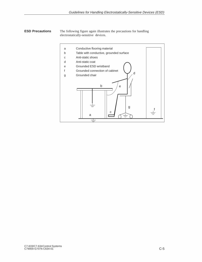
C-5C7-633/C7-634 Control SystemsC79000-G7076-C634-01
The following figure again illustrates the precautions for handlingelectrostatically-sensitive devices.
a Conductive flooring material
b Table with conductive, grounded surface
c Anti-static shoes
d Anti-static coat
e Grounded ESD wristband
f Grounded connection of cabinet
g Grounded chair
a
b
c
d
e
fg
ESD Precautions
Guidelines for Handling Electrostatically-Sensitive Devices (ESD)

C-6C7-633/C7-634 Control Systems
C79000-G7076-C634-01
C.4 Taking Measurements and Working on ESD Modules
Measurements may be taken on electrostatically-sensitive devices only if:
The measuring device is grounded (for example, via protective conductor)or
The tip of the isolated measuring device has previously been dischargedbefore use (for example, by briefly touching grounded metal parts).
C.5 Packing Electrostatically-Sensitive Devices
Always use conductive materials for packing modules without a casing andcomponents. You may also use metal-clad plastic boxes or metal containers.Always store ESD modules in conductive packing material.
When packing modules incorporating batteries, cover the battery connectionswith insulating tape or insulating material to avoid short-circuiting thebattery. Remove the battery if possible.
Use GroundedMeasuring DevicesOnly
Using ConductiveMaterial forPacking Moduleswithout a Casing
Cover Batteries
Guidelines for Handling Electrostatically-Sensitive Devices (ESD)

D-1C7-633/C7-634 Control SystemsC79000-G7076-C634-01
Literature on SIMATIC C7 and S7
/30/ Primer: S7-300 Programmable Controller, Quick Start
/70/ Manual: S7-300 Programmable Controller, Hardware and Installation
/71/ Reference Manual: S7-300 and M7-300 Programmable Controllers,Module Specifications
/72/ Instruction List: S7-300 Programmable Controller
/230/ User Manual: Standard Software for S7,Converting S5 Programs
/232/ Manual: Statement List (STL) for S7-300 and S7-400, Programming
/233/ Manual: Ladder Logic (LAD) for S7-300 and S7-400, Programming
/235/ Reference Manual: System Software for S7-300 and S7-400,System and Standard Functions
/236/ Manual: Function Block Diagram (FBD) for S7-300 and S7-400, Programming
/280/ Programming Manual: System Software for M7-300 and M7-400,Program Design
D

D-2C7-633/C7-634 Control Systems
C79000-G7076-C634-01
Literature on SIMATIC C7 and S7

Glossary-1C7-633/C7-634 Control SystemsC79000-G7076-C634-01
Glossary

Glossary-2C7-633/C7-634 Control Systems
C79000-G7076-C634-01
A
The analog I/O converts analog process values (for example, temperature)into digital values that can be processed by the C7 CPU or converts digitalvalues into analog manipulated variables.
Assigning parameters means setting the behavior of a module.
B
The backup battery guarantees that the user program in the C7 CPU is storedsafe from power failures and that data areas, bit memory, timers, andcounters remain retentive.
The backup memory backs up memory areas of the CPU without the need fora backup battery. The memory backs up a programmable number of timers,counters, bit memory, and data block bytes.
A bus is a transfer medium that connects two or more nodes together. Datatransfer can be serial or parallel, via electrical conductors or fiber-opticcables.
C
The C7 control system integrates a SIMATIC S7-300 CPU, a SIMATIC OP,the possibility of connecting to the S7-300 I/O (for example, via anintegrated IM 360), and a communication connection (for example, ASimaster, PROFIBUS DP master/slave).
The C7 CPU is the central processing unit for the C7, complete withprocessor, arithmetic unit, memory, operating system, and interfaces forprogramming devices. The C7 CPU is independent of the C7 OP. TheC7 CPU has its own MPI address and is connected to the C7 OP via the MPI(multipoint interface).
The C7 OP handles the OP functions. It is independent of the C7 CPU andcontinues to operate, for example, if the C7 CPU goes into STOP mode. TheC7 OP has its own MPI address and is connected to the C7 CPU via the MPI(multipoint interface). It is via the MPI that the C7 OP is connected to aconfiguring computer (programming device/PC).
Analog I/O
AssigningParameters
Backup Battery
Backup Memory
Bus
C7
C7 CPU
C7 OP
Glossary
Glossary-3C7-633/C7-634 Control SystemsC79000-G7076-C634-01
Communications processors are intelligent programmable modules with theirown processor. They form an important group within the components of aprogrammable controller. A distinction can be made between various types ofcommunications processors according to their tasks. For example, CPs formessages and logging, for point-to-point connection, for operator interfacing(COROS), for bus connections (SINEC), for diagnostics, and mass storageapplications.
When a CPU starts up (for example, when the mode selector is moved fromSTOP to RUN or when power is turned on), before cyclic program processingstarts (OB1), either the organization block OB101 (restart; only in theS7-400) or OB100 (complete restart) is processed first. In a complete restartthe process-image input table is read in and the STEP 7 user programprocessed starting with the first statement in OB1.
The configuration memory is a flash memory integrated in the C7 OP. It isused for storing the configuration data.
Configuring is the selection and putting together of the individualcomponents of a programmable logic controller (PLC), and the installation ofthe required software (for example, the operating system on an M7automation computer) and adapting it to the specific task (such as assigningparameters to the modules).
Communications processor
A cyclic interrupt is generated periodically by the CPU according to a timeinterval which can be assigned parameters. It triggers execution of therelevant organization block.
D
A collective term for system diagnostics, process error diagnostics, anduser-defined diagnostics.
The diagnostic buffer is a retentive area of memory within the CPU whichstores the diagnostic events in the order they occurred.
Diagnostic events include errors in a digital function in the C7, system faultsin the C7 caused, for example, by programming errors or operating modetransitions.
CommunicationsProcessor
Complete Restart
ConfigurationMemory
Configuring
CP
Cyclic Interrupt
Diagnostics
Diagnostic Buffer
Diagnostic Event
Glossary

Glossary-4C7-633/C7-634 Control Systems
C79000-G7076-C634-01
The diagnostic functions comprise the complete scope of system diagnostics,process error diagnostics, and user-defined diagnostics, and the detection,evaluation, and signaling of faults within the C7.
Modules with diagnostics capability signal system errors to the CPU bymeans of diagnostic interrupts.
E
Electrical connection (equipotential bonding conductor) that brings thebodies of electrical resources to the same or approximately the samepotential as foreign bodies in order to prevent interference or hazardousvoltages arising between the bodies.
The error display is one of the possible responses of the operating system to arun-time error. The other possible responses are: error response in the userprogram, CPU STOP mode.
F
FEPROMs correspond to the electrically erasable EEPROMs, but can beerased much faster (FEPROM = Flash Erasable Programmable Read-OnlyMemory). They are used on the memory cards.
Flash EPROM
Grounding with the sole purpose of ensuring the intended purpose of theelectrical resources. Function grounding has the effect of short-circuitinginterference voltages that would otherwise have an impermissible influenceon the resources.
A function module (FM) is a module which relieves the CPU in the S7-300and S7-400 programmable logic controllers of time-critical andmemory-intensive process signal processing tasks. Function modulesgenerally use the internal communication bus for high-speed data exchangewith the CPU. Examples for function module applications are: counting,positioning, closed-loop control.
DiagnosticFunctions
DiagnosticInterrupt
EquipotentialBonding
Error Display
Flash EPROM
Flash Memory
Functional Ground
Function Module(FM)
Glossary

Glossary-5C7-633/C7-634 Control SystemsC79000-G7076-C634-01
G
Conductive ground whose electrical potential at any point can be taken aszero. In the area of grounding electrodes, the ground can have a potentialother than zero. This is frequently referred to as the “reference ground.”
To connect an electrically conductive part with the grounding electrode (oneor more conductive parts that have very good contact to ground) by means ofa grounding point.
H
A hardware interrupt is triggered by interrupt-triggering modules as the resultof certain events in the process. The hardware interrupt is signaled to the C7CPU. Depending on the priority of the interrupt, the correspondingorganization block is then executed.
I
The information functions of the STEP 7 programming software permit thedisplay of status information from the CPU (for example, information aboutmemory space or cycle time statistics).
SIMATIC S7 recognizes 28 different priority classes which control theprocessing of the user program. These priority classes include interrupts, suchas hardware interrupts. When an interrupt occurs, the relevant organizationblock is called automatically by the operating system in which the user canprogram the required reaction to the interrupt (for example, in a functionblock (FB)).
In isolated I/O modules, the reference potentials of the control circuit and theload circuit are electrically isolated by, for example, optocouplers, relaycontactors, or transformers. Input/output circuits can be connected tocommon potential.
Ground
Ground (Verb)
Hardware Interrupt
InformationFunction
Interrupt
Isolated
Glossary

Glossary-6C7-633/C7-634 Control Systems
C79000-G7076-C634-01
L
The load memory is part of a programmable module. It contains objectscreated by the programming device (load objects). It can be either a plug-inmemory card or an integrated memory. In SIMATIC M7 the load memorycan be defined as a directory on the hard disk.
M
A memory card is a memory submodule in credit-card format and in the formof RAM or FEPROM for programmable modules and CPUs which can storethe user program and parameters.
The memory reset function deletes the following memories in the CPU:
Work memory
Read/write area of the load memory
System memory
In S7/M7/C7 the MPI parameters and the diagnostic buffer are retained. InM7 the operating system is also rebooted if the M7 was reset via the modeselector. In SIMATIC HMI devices, all buffers are cleared. The MPI addressis reset to the default value.
Memory card
Multipoint interface
A network is the connection of a number of C7 and/or S7-300 and otherdevices, such as a programming device, via a connecting cable. Data areexchanged between the connected devices over the network.
The multipoint interface (MPI) is the programming device interface inSIMATIC S7. It allows a number of programmable modules, text displayoperator panels, and operator panels (OPs) to be accessed from a CPU. Thenodes on the MPI can communicate with each other.
Load Memory
Memory Card
Memory Reset(MRES)
MemorySubmodule
MPI
MPI Network
MultipointInterface
Glossary

Glossary-7C7-633/C7-634 Control SystemsC79000-G7076-C634-01
N
The node number represents the “access address” of a CPU or aprogramming device or other intelligent I/O module when it communicateswith other nodes via a network. The node number is assigned to the CPU orthe programming device using the “S7 Configuration” application.
In non-isolated I/O modules, the reference potentials of the control circuitand the load circuit are electrically connected.
O
A collective term for all functions which, in conjunction with the hardware,control and monitor the execution of the user programs, the distribution ofthe operational equipment among the individual user programs, and themaintenance of the operating mode (for example, MS-DOS).
P
1. A parameter is a variable in a STEP 7 logic block (see block parameter,actual parameter, formal parameter).2. A parameter is also a variable for setting the behavior of a module (one ormore per module). Every programmable module has a basic parameter setting when it is shippedfrom the factory, but this can be changed by configuring the hardware. Thereare two types of parameters: static and dynamic parameters.
Dynamic parameters of modules, in contrast to static parameters, can bechanged by the user program during operation by calling an SFC in S7 andby calling a function in M7, for example, limit values of an analog inputmodule.
Static parameters of modules, in contrast to dynamic parameters, cannot bechanged by the user program, but only by configuring the hardware, forexample, the input delay of a digital input module.
Programming device
Programmable logic controller
Node Number
Non-Isolated
Operating System
Parameter
Parameter,Dynamic
Parameter, Static
PG
PLC
Glossary
Glossary-8C7-633/C7-634 Control Systems
C79000-G7076-C634-01
The signal states of the digital input and output modules are stored in theCPU in a process image. There is a process-image input table (PII) and aprocess-image output table (PIQ).
The process-image output table is transferred to the output modules by theoperating system at the end of the user program.
The process-image input table is read by the input modules before executionof the user program by the operating system.
Programmable logic control is the automation technique using electroniccontrollers whose function is stored in the control device as a program. Thestructure and the wiring of the device are not therefore dependent on thefunction of the controller. A programmable logic controller has the structureof a computer; it consists of a CPU with memory, I/O modules, and internalbus system. The I/O and the programming language are set up according tothe requirements of control engineering.
A programmable logic controller (PLC) comprises a central processor, aCPU, and a number of I/O modules.
Programming devices are essentially personal computers that are compactand portable and suitable for industrial use. They are characterized by beingequipped with special hardware and software for programming SIMATICprogrammable controllers.
R
The Random Access Memory or RAM is a read/write memory in which eachmemory location can be addressed individually and have its contentschanged. RAM is used as a memory for data and programs.
The reference ground is the total of all connected conductive inactive parts ofan operating resource that cannot carry a hazardous touch voltage even in theevent of a fault.
Potential from which the voltages of the connected circuits are consideredand/or measured.
Process Image
ProgrammableLogic Control
ProgrammableLogic Controller
ProgrammingDevice
RAM
Reference Ground
ReferencePotential
Glossary

Glossary-9C7-633/C7-634 Control SystemsC79000-G7076-C634-01
S
The scan cycle time is the time the CPU takes to run the user program oncethrough. The scan cycle time for analog modules is the time in which all thechannels (input and output channels) are converted and the next conversioncan start.
Signal modules (SM) form the interface between the process and theprogrammable controller. There are digital input modules, output modules,and in/out modules and analog input modules, output modules, and in/outmodules.
Programming software for creating user programs for SIMATIC S7programmable controllers.
A STEP 7 application is a tool of STEP 7 which is tailored to a specific task.
Substitute values are values which are output to the process in the case offaulty signal output modules or which are used in the user program instead ofa process variable in the case of faulty signal input modules. The substitutevalues can be specified in advance by the user (for example, retain lastvalue). They are values which the outputs are to output when the CPU goesinto STOP.
System diagnostics comprises the detection, evaluation, and signaling oferrors which occur within the programmable controller. Examples of sucherrors include: program errors or module faults.
The system memory is integrated in the S7 CPU in the form of RAM. Theaddress areas (for example, timers, counters, bit memory) and data areasrequired internally by the operating system (for example, backup forcommunication) are stored in the system memory. In M7, the system memoryis not a separate area but is integrated in the work memory.
T
The time-delay interrupt belongs to one of the priority classes in SIMATICS7 program processing. It is generated when a timer has expired in the userprogram. It triggers execution of the relevant organization block.
Scan Cycle Time
Signal Module
STEP 7
STEP 7Application
Substitute Value
SystemDiagnostics
System Memory
Time-DelayInterrupt
Glossary

Glossary-10C7-633/C7-634 Control Systems
C79000-G7076-C634-01
The time-of-day interrupt belongs to one of the priority classes in theprogram processing of the C7 CPU. It is generated at a specific date (ordaily) and time (for example, at 9:50 or every hour or every minute). Ittriggers execution of the relevant organization block.
Sum of the currents of all output channels of a digital output module.
Data transmission rate in bits per second (bps).
U
Without electrical connection to ground.
A diagnostic event recognized by the user which can be entered in thediagnostic buffer (via SFC52).Note: If the entry is prepared in the diagnostic buffer in clear text and sent, amessage appears.
The user memory contains the logic blocks and data blocks of the userprogram. The user memory is either integrated in the CPU or in the form ofinsertable memory cards or memory submodules. The user program is,however, always executed from the internal RAM memory of the CPU.
The user program contains all the statements and declarations and the datarequired for signal processing to control a plant or a process. The program islinked to a programmable module (for example CPU or function module) andcan be structured in the form of smaller units (blocks).
V
Voltage-dependent resistor
W
The work memory is a random-access memory (RAM) in the CPU which theprocessor accesses while executing the user program.
Time-of-DayInterrupt
Total Current
Transmission Rate
Ungrounded
User-DefinedDiagnostic Event
User Memory
User Program
Varistor
Work Memory
Glossary

Index-1C7-633/C7-634 Control SystemsC79000-G7076-C634-01
Index
4-wire transducerconnection, 7-6measuring ranges, 7-10
AAccessories, 1-5Acknowledgement, 4-5
area, 4-5, 4-6bit, 4-5
Acknowledgement areas, size, 4-7Actual value of counter, 8-14
calculating, 8-14Additional information, 7-35, 8-12, 8-13Addresses
analog function, 7-18universal input, 8-6
Addressing, 6-9Addressing recipes and data records, 4-20Alarm acknowledgement, number, 4-4Alarm message area, setting the bit, 4-4Analog function, parameter, 7-21Analog I/O, behavior, 7-33Analog input
diagnostics, 10-4isolated, 7-3parameter, 7-22
Analog input function, 7-10technical specifications, 7-14
Analog input modulecharacteristics, 7-11technical specifications, 7-11terminal connection diagram, 7-12
Analog input module SM 331; AI 8, wire breakcheck, 7-10
Analog inputs, measurement ranges, 7-10, 7-28Analog inputs/outputs, 2-11Analog output
diagnostics, 10-4output ranges, 7-30parameters, 7-25
Analog output function, 7-15technical specifications, 7-17terminal connection diagram, 7-16
Analog rangesresolution, 7-27sign conventions, 7-27
Analog signal, cable for, 7-3, 7-7Analog-digital conversion, 7-31Area pointer, screen number area, 4-12Assigning parameters, universal inputs, 8-4AUX digital inputs, 2-12
BBackup battery
changing, 11-2disposal, 11-3service life, 11-3storage, 11-3transport and storage, B-13
Basic setting, parameter block, 7-22, 7-25BATF, 3-7Battery, backup, 11-2Battery fault, 3-7Bit number, 4-11Bus connector, 2-16
CC7
functions, 1-4installing, 2-5
C7 accessories, 1-5C7 CPU, 1-4, Glossary-2C7 cutout, 2-6C7 I/O diagnostics, 10-2C7 I/O module, 1-7C7 OP, 1-4, Glossary-2C7 simulator module, 1-7Cabinet installation, 2-20

Index-2C7-633/C7-634 Control Systems
C79000-G7076-C634-01
Cablefor analog signals, 7-3, 7-7
Cables, 2-20Category, system message, A-1Causes, system message, A-2CE marking, B-11Change language, control job, 4-26Channel-specific, diagnostic byte, 10-6CI1, 8-7CI2, 8-7CI3, 8-7Communication
MPI subnet, 5-3PROFIBUS DP, 5-5
Communication functions, 5-2Communication SFCs, non-configured S7
connections, 5-3Communications processors (CP), 1-6Configurable, events, 7-35Configuration error, 7-22, 7-25Configuration memory, Glossary-3Connecting cable, PROFIBUS, 1-7Connecting cable 368, 2-25Connectors, 2-23
view, 2-13Control and checkback bits, 4-15Control job, 4-24
change language, 4-26cursor positioning, 4-30data record to CPU, 4-29data record to OP, 4-29delete alarm message buffer, 4-28delete event message buffer, 4-28display mode for alarm messages, 4-27fetch acknowledgement area, 4-28fetch alarm message bit area, 4-28fetch event message bit area, 4-28hardcopy, 4-25interface parameters, 4-26keyboard simulation, 4-30menu selection, 4-28message log on/off, 4-26overflow warning on/off, 4-28parameters, 4-25partial screen updating, 4-29password logout, 4-27print alarm message buffer, 4-27print all screens, 4-25print event message buffer, 4-27print recipe, 4-25, 4-29
print screen, 4-29printer parameters, 4-27screen selection, 4-29select contents, 4-25select recipe, 4-29select special screens, 4-25set contrast, 4-27set date, 4-26set password level, 4-27set time, 4-26SIMATIC S7, 4-17structure, 4-24transfer date/time, 4-28
Conversion, analog output, 7-32Conversion time, analog input, 7-31Count direction, setting, 8-10Count inputs, parameter block, 8-10Counter
start, 8-15stop, 8-15threshold frequency, 8-14universal inputs, 8-14
Counter inputparameter, 8-9universal inputs, 8-2, 8-4
Counting down, 8-14Counting up, 8-14Coupling identifier, 4-17CPU operating mode, selecting, 3-4CSA, B-10Current measurement, 7-10Current measurement range
analog input, 7-29analog output, 7-30
Current transducer, 7-3Cursor lock, 4-30Cursor positioning, control job, 4-30Cycle time
analog input, 7-31analog output, 7-32
Cyclic interrupt bits, 4-15, 4-18Cyclic interrupt times, 4-18
DData area
screen number area, 4-12system keyboard image, 4-9
Data recordrecipes, 4-19transfer, 4-20
synchronization, 4-21
Index

Index-3C7-633/C7-634 Control SystemsC79000-G7076-C634-01
Data record to CPU, control job, 4-29Data record to OP, control job, 4-29Data records, addressing, 4-20Date, 4-15Date and time, 4-17Delete alarm message buffer, control job, 4-28Delete event message buffer, control job, 4-28DI/DO 24 VDC power supply, 2-12DI/DO status display, 3-6, 6-8Diagnostic
interrupt, 7-34parameter assignment, 10-2
Diagnostic area, layout, 10-4Diagnostic entry, channel-specific, 10-6Diagnostic error
permanent, 10-3temporary, 10-3
Diagnostic evaluation, 10-8Diagnostic events, 10-2Diagnostic messages
reaction, 10-9read, 10-3
Diagnosticsanalog input, 10-4analog output, 10-4C7 I/O, 10-2enabling, 10-4message, 7-34parameter block, 7-22, 7-25, 10-4
Digital input, universal inputs, 8-2, 8-4Digital input function, technical specifications,
6-4Digital inputs, 2-9
universal inputs, 8-11Digital output function, special features, 6-5Digital outputs, 2-10, 6-5Dimensions, labeling strips, 2-3Display, contrast, 4-27Display mode for alarm messages, control job,
4-27Dynamic, parameters, 7-21
EEnable diagnostic interrupt, 7-22, 7-25Enabling, diagnostics, 10-4Error handling, A-2Error indicator, LEDs, 3-7Errors, internal, A-2EU Directive, Machinery, B-12Event, assignable, 8-12Event message area, setting the bit, 4-4
Events, configurable, 7-35External gate counter, 8-22
FFetch acknowledgement area, control job, 4-28Fetch alarm message bit area, control job, 4-28Fetch event message bit area, control job, 4-28File, labeling strips, 2-2Flash EPROM, Glossary-4Flash memory, Glossary-4FM approval, B-10FRCE, 3-7Frequency calculation, 8-17Frequency counter
parameter, 8-9universal inputs, 8-2, 8-4
Function keyboard image, 4-10Function keys, labeling, 2-2Function modules (FM), 1-6Functional ground, 2-14Functions, C7, 1-4
GGate counter, external, 8-22Gate time measurement, 8-22Grounding, 2-20Grounding bar, installing, 2-22Grounding rail, 2-20Group error, CPU, 3-7Guidelines, for setup, 2-20
HHardcopy, control job, 4-25Hardware interrupt, 8-12
events, 8-12
IIM 360, 2-24IM 361 cable, 2-16Increments, 8-19Input 24 VDC, 2-13Input range, universal inputs, 8-7Installation, interference-free, 2-20Installation guidelines, 2-6Installing C7, 2-5Integrated interface module, 2-24
Index

Index-4C7-633/C7-634 Control Systems
C79000-G7076-C634-01
Interface module, 1-6Interface module IM 360, 2-24Interface parameters, control job, 4-26Interference signals, 2-20Interference-free installation, 2-20Internal errors, A-2Interrupt, 7-22, 8-12Interrupt cycle, 7-22, 7-31, 7-35
interrupt time, 7-22parameter block, 7-22
Interrupt input, 8-2universal inputs, 8-2, 8-4
Interrupt OB, 7-35, 8-12Interrupt time, parameter block, 7-22
JJob area, 4-17
KKey assignment, function keyboard image, 4-10Keyboard
C7-633, 3-2C7-634, 3-3group bit
function keyboard, 4-10system keyboard image, 4-9
variations, 3-2Keyboard simulation, control job, 4-30Keying connectors, 2-23Keyswitch, 3-2
LLabeling, function keys, 2-2Labeling strips, 2-2
changing, 2-4cutting, 2-2dimensions, 2-3making, 2-2template, 2-2
Labeling template, function keys, 2-2LED
assignment, 4-11states, 4-11
LED assignment, bit number, 4-11LED image, 4-11LEDs, 3-7
List, system messages, A-1Lock, cursor, 4-30Lower threshold, period time, 8-21
MMachinery Directive, SIMATIC, B-12Measured value resolution, 7-28Measurement
parameter block, 7-22type of, 7-22
Measurement period, frequency calculation,8-17
Measurement ranges, 7-27analog inputs, 7-10, 7-28
Memory reset, MRES, 3-5Menu selection, control job, 4-28Message, triggering, 4-4Message areas, 4-4Message bit, 4-4Message level, display number area, 4-12Message log on/off, control job, 4-26Message number, 4-4, A-1Mode selector switch, 3-2MPI interface, connector assignment, 2-15MPI network, connecting programming device,
2-17, 2-18MPI subnet, communication, 5-3MRES, 3-5
NNon-configured S7 connections, 5-3
OOB 40, 7-35OB40, 8-12OP operation mode, 4-16OP startup, 4-16Operating mode, selecting, 3-4Operator panel (OP), 1-7Output range
addresses, 8-8parameter block, 7-25universal inputs, 8-8
Output ranges, 7-27analog output, 7-30
Overflow warning on/off, control job, 4-28
Index

Index-5C7-633/C7-634 Control SystemsC79000-G7076-C634-01
PParameter
analog function, 7-21analog input, 7-22analog output, 7-25
Parameter assignment, universal inputs, 8-9Parameter assignment error, 7-22, 7-25Parameter block
basic setting, 7-22, 7-25count inputs, 8-10diagnostics, 7-22, 7-25, 10-4interrupt cycle, 7-22measurement, 7-22output range, 7-25substitute value, 7-25
Parameter characteristicsanalog inputs, 7-24analog output, 7-26
Parameter tools, universal inputs, 8-9Partial screen updating, control job, 4-29Password logout, control job, 4-27Period, 8-19Period duration counter, universal inputs, 8-2,
8-4Period time, lower threshold, 8-21Period time counter, 8-19
parameter, 8-9parameter assignment, 8-21
Period time measurement, 8-19Permanent, diagnostic error, 10-3Plug and socket connectors, view, 2-9Print alarm message buffer, control job, 4-27Print all screens, control job, 4-25Print event message buffer, control job, 4-27Print recipe, control job, 4-25, 4-29Print screen, control job, 4-29Printer, 1-7Printer cable, 1-5Printer parameters, control job, 4-27Printing, labeling strips, 2-2PROFIBUS, connecting cable, 1-7PROFIBUS bus cable, 2-16PROFIBUS bus terminal, 2-16PROFIBUS-DP, communication, 5-5PROFIBUS-DP interface, connector
assignment, 2-15
Programming device, 1-8connecting for maintenance, 2-19connecting to MPI, 2-17, 2-18for service purposes, 2-19in MPI network, 2-18
Programming device cable, 2-16MPI, 1-7TTY, 1-7
Programming the counters, example, 8-23
RRange overshoot, 7-22Range undershoot, 7-22Reaction, to diagnostic messages, 10-9Ready bit, 4-16Recipe, addressing, 4-20Recipes, 4-19
overview, 4-19transferring data records, 4-19, 4-20
Relatively constant frequencies, resolution, 8-18Remedies, system message, A-2Replacing, labeling strips, 2-4Resolution, analog ranges, 7-27Response time, analog output, 7-32RS 232/TTY interface, 2-14RS 485 repeater, 1-8RUN, 3-5, 3-7RUN-P, 3-5
SS7-300 (CPU), 1-6S7-400 (CPU), 1-6Screen number area, 4-12Screen selection, control job, 4-29Select contents, control job, 4-25Select count, edge, 8-10Select recipe, control job, 4-29Select special screens, control job, 4-25Set contrast, control job, 4-27Set date, control job, 4-26Set password level, control job, 4-27Set time, control job, 4-26Settling time, analog output, 7-32
Index
Index-6C7-633/C7-634 Control Systems
C79000-G7076-C634-01
SF, 3-7Shielding, 2-20Shielding clips, 2-22SHIFT keys, 4-8Sign conventions, analog ranges, 7-27Signal modules (SM), 1-6SIMATIC S7
alarm messages, 4-4control jobs, 4-17date and time, 4-15event messages, 4-4function keyboard image, 4-10images, 4-8LED image, 4-11recipes, 4-19screen number area, 4-12system keyboard image, 4-9transferring data records, 4-20user version, 4-13
SIMATIC S7 connection, cyclic interrupt bits,4-15
SIMATIC S7 couplingcontrol and checkback bits, 4-15coupling identifier, 4-17date and time, 4-17job area, 4-17OP operating mode, 4-16OP startup, 4-16ready bit, 4-16
SIMATIC TOP Connect, 1-7Size, labeling strips, 2-3SLIDE633.DOC, file, 2-2SLIDE634.DOC, file, 2-2Slot number, 8-20Spare parts, 1-5Special screens, screen number area, 4-12Start counter, 8-15State, universal input, 8-7Static, parameter, 7-21Status display, DI/DO, 3-6, 6-8Status indicator, LEDs, 3-7STOP, 3-5, 3-8Stop counters, 8-15Storing, backup battery, 11-3Substitute value, parameter block, 7-25System keyboard image, 4-9System messages, list of, A-1
TTemplate, labeling strips, 2-2Temporary, diagnostic error, 10-3Threshold frequency
counter, 8-14exceeding, 8-14, 8-18
Time, 4-15Time interrupt, 7-35Transducer
isolated, 7-4non-isolated, 7-5
Transfer, data records, 4-20, 4-21Transfer date/time, control job, 4-28Type of measurement, 7-22
UUL, B-10Universal input, addresses, 8-6Universal inputs
assigning parameters, 8-4counter, 8-14parameter assignment, 8-9pin assignments, 8-4technical specifications, 8-5
Update time, 4-23Upper threshold, period time, 8-21User data area, optimization, 4-23User data areas, functionality, 4-3User version, 4-13
VVariations, keyboard, 3-2Voltage measurement, 7-10Voltage measurement range
analog input, 7-29analog output, 7-30
Voltage transducer, 7-3connection, 7-6
WWire break, 7-22Wire break check, analog input module SM 331;
AI 8, 7-10
Index

1C7-633/C7-634 Control SystemsC79000-G7076-C634-01
Siemens AG
A&D AS E 81
Oestliche Rheinbrueckenstr. 50
D-76181 Karlsruhe
Federal Republic of Germany
Please check any industry that applies to you:
Automotive
Chemical
Electrical Machinery
Food
Instrument and Control
Nonelectrical Machinery
Petrochemical
Pharmaceutical
Plastic
Pulp and Paper
Textiles
Transportation
Other _ _ _ _ _ _ _ _ _ _ _
From:
Your Name:_ _ _ _ _ _ _ _ _ _ _ _ _ _ _ _ _ _ _ _ _ _ _ _ _ _ _ _ _
Your Title: _ _ _ _ _ _ _ _ _ _ _ _ _ _ _ _ _ _ _ _ _ _ _ _ _ _ _ _ _
Company Name: _ _ _ _ _ _ _ _ _ _ _ _ _ _ _ _ _ _ _ _ _ _ _ _ _ _
Street: _ _ _ _ _ _ _ _ _ _ _ _ _ _ _ _ _ _ _ _ _ _ _ _ _ _
City, Zip Code_ _ _ _ _ _ _ _ _ _ _ _ _ _ _ _ _ _ _ _ _ _ _ _ _ _
Country: _ _ _ _ _ _ _ _ _ _ _ _ _ _ _ _ _ _ _ _ _ _ _ _ _ _
Phone: _ _ _ _ _ _ _ _ _ _ _ _ _ _ _ _ _ _ _ _ _ _ _ _ _ _

2C7-633/C7-634 Control Systems
C79000-G7076-C634-01
Additional comments:
_ _ _ _ _ _ _ _ _ _ _ _ _ _ _ _ _ _ _ _ _ _ _ _ _ _ _ _ _ _ _ _ _ _ _
_ _ _ _ _ _ _ _ _ _ _ _ _ _ _ _ _ _ _ _ _ _ _ _ _ _ _ _ _ _ _ _ _ _ _
_ _ _ _ _ _ _ _ _ _ _ _ _ _ _ _ _ _ _ _ _ _ _ _ _ _ _ _ _ _ _ _ _ _ _
_ _ _ _ _ _ _ _ _ _ _ _ _ _ _ _ _ _ _ _ _ _ _ _ _ _ _ _ _ _ _ _ _ _ _
_ _ _ _ _ _ _ _ _ _ _ _ _ _ _ _ _ _ _ _ _ _ _ _ _ _ _ _ _ _ _ _ _ _ _
_ _ _ _ _ _ _ _ _ _ _ _ _ _ _ _ _ _ _ _ _ _ _ _ _ _ _ _ _ _ _ _ _ _ _
_ _ _ _ _ _ _ _ _ _ _ _ _ _ _ _ _ _ _ _ _ _ _ _ _ _ _ _ _ _ _ _ _ _ _
_ _ _ _ _ _ _ _ _ _ _ _ _ _ _ _ _ _ _ _ _ _ _ _ _ _ _ _ _ _ _ _ _ _ _
_ _ _ _ _ _ _ _ _ _ _ _ _ _ _ _ _ _ _ _ _ _ _ _ _ _ _ _ _ _ _ _ _ _ _
_ _ _ _ _ _ _ _ _ _ _ _ _ _ _ _ _ _ _ _ _ _ _ _ _ _ _ _ _ _ _ _ _ _ _
_ _ _ _ _ _ _ _ _ _ _ _ _ _ _ _ _ _ _ _ _ _ _ _ _ _ _ _ _ _ _ _ _ _ _
_ _ _ _ _ _ _ _ _ _ _ _ _ _ _ _ _ _ _ _ _ _ _ _ _ _ _ _ _ _ _ _ _ _ _
Remarks Form
Your comments and recommendations will help us to improve the quality and usefulnessof our publications. Please take the first available opportunity to fill out this questionnaireand return it to Siemens.
Please give each of the following questions your own personal mark within the rangefrom 1 (very good) to 5 (poor).
1. Do the contents meet your requirements?
2. Is the information you need easy to find?
3. Is the text easy to understand?
4. Does the level of technical detail meet your requirements?
5. Please rate the quality of the graphics/tables:


![C7 graham session c7 mon1530_v6[2]](https://img.dokumen.tips/doc/110x75/58ed94c51a28ab717c8b475d/c7-graham-session-c7-mon1530v62.jpg)

