Embed Size (px)
Citation preview
This is not a polished document and has not gone through a formal review process. It is intended to be a starting point user can adapt to the particular situation. You should change and edit the presentation to make it your own.
Quantity Part Description Part Number Jamco Number Cost (2004)
1 Mastech Mulitmeter M830B 220855CR $9.95
1 Solderless Breadboards JE24 20757CR $9.95
1 Jumper Wires* JE27 77825CR $12.95
1 9V Battery Holder BH-9V-A 216426CR $0.79
1 1.5V Battery Holder BH-311-2A 216071CR $0.69
1 100 ohm ** 29946CR
1 200 ohm 59424CR
1 330 ohm 30867CR
2 1000 ohm 29663CR
1 2.2K ohm 30314CR
2 4.7k ohm 31026CR
1 10K ohm 29911CR
1 100K ohm 29997CR
1 100uF Electrolytic Cap 94431CR $0.09
1 Diode 1N914 179207CR $0.05
1 Zener Diode 1N4732A 36089CR $0.06
1 Transistor 2N3604 178597CR $0.09
1 LED LH2040 94529CR $0.19
* More jumpers than needed for one student, can be shared to reduce costs
Basic Electronics Course Standard Parts List
** Individual components are often sold is quantity, quantity purchase can be shared
between students to reduce costs.

This course is intended for those interested
in learning the basics of electronics. The
topics discussed during the course are
listed here in a brief outline. The topics
up to and including Ohm’s law are
considered the most basic. The remaining
topics cover additional fundamental
components of basic electronics, however,
they will only receive brief coverage.
The course will be presented in platform
discussion, guided practice, and open
question format, as the material dictates. The course uses a standard volt-ohm-meter
(VOM) for illustration. If the participant has a different VOM the range settings and or
readouts may be slightly different. The readings for the sample activities given in this
presentation are based on the readings found while using the specified components they
are provided for illustration purposes only. Your readings may be different.
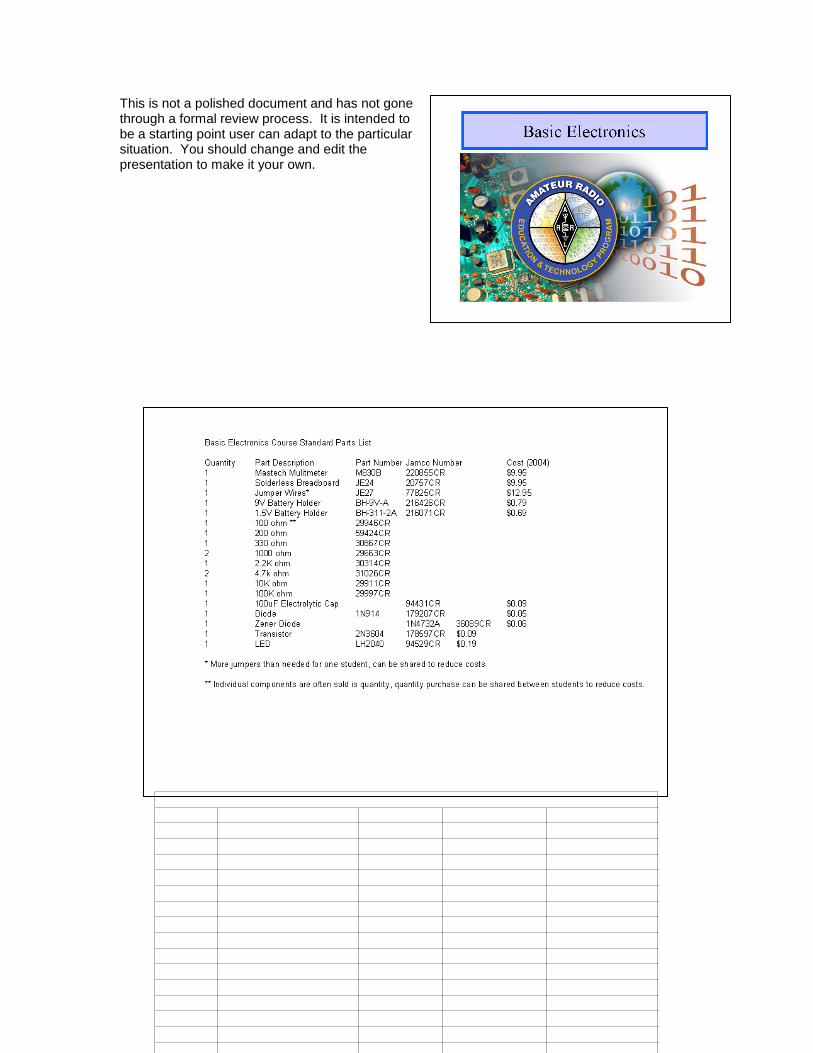
We will begin by discussing the three
fundamental parameters that define
electricity. Extensive time will then be
spent on how to measure the three
components of electricity. During this
section two of the three components
(voltage and current) will be explored.
This section will cover VOM
measurement basics and allow you to
become familiar with the most important
piece of basic test equipment. The next
section on circuit diagrams will show how
electronic components are symbolized on an electronic road map called a schematic or
circuit diagram. Many of the symbols presented will represent new concepts for many of
you and these concepts will not be fully developed before the section is covered. Some
will not be developed at all during the course. The intention here is to establish the
fundamentals of interpreting circuit diagrams so that these illustrations of the
arrangement of electronic components can be used to help with the remainder of the
course. The final of the three components, resistors, will be covered next. How the three
components are related mathematically is Ohm’s law and this fundamental law will be
covered in detail. These sections make up the very basic material of electronics.
Four additional components common to virtually all electronic circuits are the capacitor,
inductor, diode, and transistor. These topics will be covered with a level of detail that
will familiarize the students with the function of these components and the basics of how
they work and react in difference situations.
ARRL’s Understanding Basic Electronics is an excellent supplementary reference for
this course.
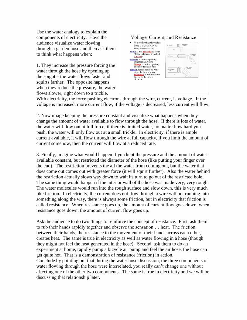
Use the water analogy to explain the
components of electricity. Have the
audience visualize water flowing
through a garden hose and then ask them
to think what happens when:
1. They increase the pressure forcing the
water through the hose by opening up
the spigot – the water flows faster and
squirts farther. The opposite happens
when they reduce the pressure, the water
flows slower, right down to a trickle.
With electricity, the force pushing electrons through the wire, current, is voltage. If the
voltage is increased, more current flow, if the voltage is decreased, less current will flow.
2. Now image keeping the pressure constant and visualize what happens when they
change the amount of water available to flow through the hose. If there is lots of water,
the water will flow out at full force, if there is limited water, no matter how hard you
push, the water will only flow out at a small trickle. In electricity, if there is ample
current available, it will flow through the wire at full capacity, if you limit the amount of
current somehow, then the current will flow at a reduced rate.
3. Finally, imagine what would happen if you kept the pressure and the amount of water
available constant, but restricted the diameter of the hose (like putting your finger over
the end). The restriction prevents the all the water from coming out, but the water that
does come out comes out with greater force (it will squirt further). Also the water behind
the restriction actually slows way down to wait its turn to go out of the restricted hole.
The same thing would happen if the interior wall of the hose was made very, very rough.
The water molecules would run into the rough surface and slow down, this is very much
like friction. In electricity, the current does not flow through a wire without running into
something along the way, there is always some friction, but in electricity that friction is
called resistance. When resistance goes up, the amount of current flow goes down, when
resistance goes down, the amount of current flow goes up.
Ask the audience to do two things to reinforce the concept of resistance. First, ask them
to rub their hands rapidly together and observe the sensation … heat. The friction
between their hands, the resistance to the movement of their hands across each other,
creates heat. The same is true in electricity as well as water flowing in a hose (though
they might not feel the heat generated in the hose). Second, ask them to do an
experiment at home, rapidly pump a bicycle air pump and feel the air hose, the hose can
get quite hot. That is a demonstration of resistance (friction) in action.
Conclude by pointing out that during the water hose discussion, the three components of
water flowing through the hose were interrelated, you really can’t change one without
affecting one of the other two components. The same is true in electricity and we will be
discussing that relationship later.

Emphasize that the type of current is based
on how the current flows in a wire. If it
flows only in one direction, the current is
called Direct Current (DC), if the current
alternates from flowing in one direction
one moment and then reversing to the
other direction the next moment, the
current is called Alternating Current (AC).
Also emphasize that current magnitude
(amplitude) is not a determinant of current
type. DC does not have to be constant, as
is normally the case of current flowing
from a battery; DC only flows in one
direction even if the amplitude varies.
Discuss the sources of DC and AC. Make note that both types of current are used in
electronic devices. DC is generally used as a source of power for circuits. AC is
generally used as signal sources to transfer energy or intelligence (information such as
voice, media such as radio waves).
Point out that there are dedicated circuits within an electronic device that converts AC to
DC and DC to AC, and from one type of AC current to another.
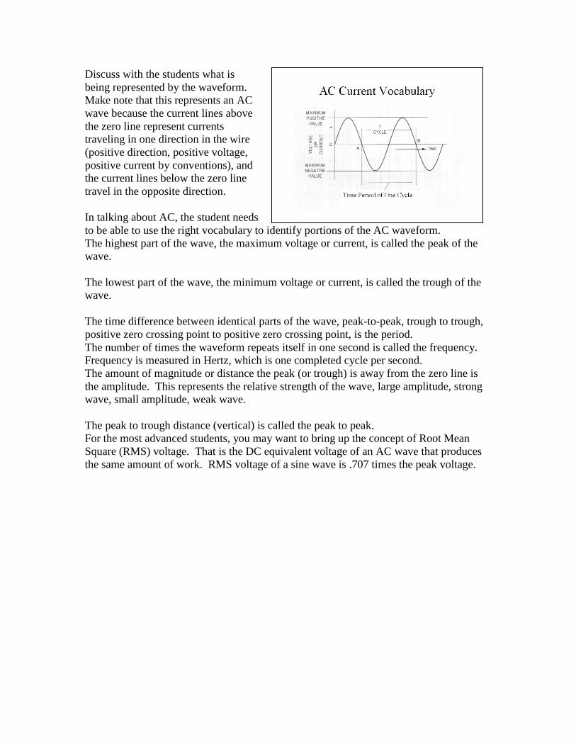
Discuss with the students what is
being represented by the waveform.
Make note that this represents an AC
wave because the current lines above
the zero line represent currents
traveling in one direction in the wire
(positive direction, positive voltage,
positive current by conventions), and
the current lines below the zero line
travel in the opposite direction.
In talking about AC, the student needs
to be able to use the right vocabulary to identify portions of the AC waveform.
The highest part of the wave, the maximum voltage or current, is called the peak of the
wave.
The lowest part of the wave, the minimum voltage or current, is called the trough of the
wave.
The time difference between identical parts of the wave, peak-to-peak, trough to trough,
positive zero crossing point to positive zero crossing point, is the period.
The number of times the waveform repeats itself in one second is called the frequency.
Frequency is measured in Hertz, which is one completed cycle per second.
The amount of magnitude or distance the peak (or trough) is away from the zero line is
the amplitude. This represents the relative strength of the wave, large amplitude, strong
wave, small amplitude, weak wave.
The peak to trough distance (vertical) is called the peak to peak.
For the most advanced students, you may want to bring up the concept of Root Mean
Square (RMS) voltage. That is the DC equivalent voltage of an AC wave that produces
the same amount of work. RMS voltage of a sine wave is .707 times the peak voltage.
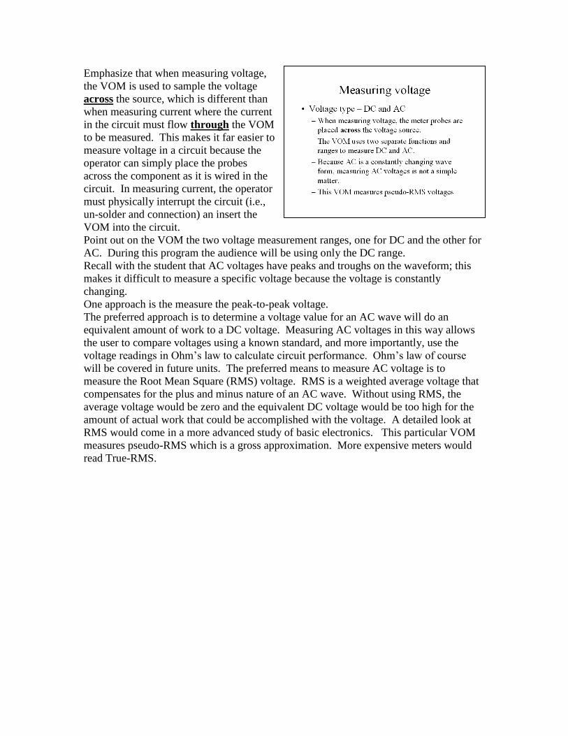
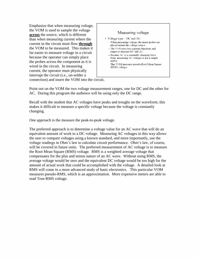
Emphasize that when measuring voltage,
the VOM is used to sample the voltage
across the source, which is different than
when measuring current where the current
in the circuit must flow through the VOM
to be measured. This makes it far easier to
measure voltage in a circuit because the
operator can simply place the probes
across the component as it is wired in the
circuit. In measuring current, the operator
must physically interrupt the circuit (i.e.,
un-solder and connection) an insert the
VOM into the circuit.
Point out on the VOM the two voltage measurement ranges, one for DC and the other for
AC. During this program the audience will be using only the DC range.
Recall with the student that AC voltages have peaks and troughs on the waveform; this
makes it difficult to measure a specific voltage because the voltage is constantly
changing.
One approach is the measure the peak-to-peak voltage.
The preferred approach is to determine a voltage value for an AC wave will do an
equivalent amount of work to a DC voltage. Measuring AC voltages in this way allows
the user to compare voltages using a known standard, and more importantly, use the
voltage readings in Ohm’s law to calculate circuit performance. Ohm’s law of course
will be covered in future units. The preferred means to measure AC voltage is to
measure the Root Mean Square (RMS) voltage. RMS is a weighted average voltage that
compensates for the plus and minus nature of an AC wave. Without using RMS, the
average voltage would be zero and the equivalent DC voltage would be too high for the
amount of actual work that could be accomplished with the voltage. A detailed look at
RMS would come in a more advanced study of basic electronics. This particular VOM
measures pseudo-RMS which is a gross approximation. More expensive meters would
read True-RMS.
Circuit is a word to describe a pathway for the flow of electrons. A good analogy is a
racetrack for motor vehicle races. The vehicles run on the track. If there is a blockage or
cut in the track, the race stops. If there is a shortcut, some of the vehicles will take that
shortcut and get to the finish line by cheating. The path concept will become more
important in future units to understand parallel and series circuits.
In electronics, there are three types of circuits. Open, Closed, and Short.
In an open circuit, the pathway (the conductor) is broken by some means and there is no
complete pathway for the electrons to flow, and so they do not flow. A good example of
an open circuit is an on/off switch. When the switch is in the off position, a portion of
the switch mechanism that connects the electronic components to the power source is
disconnected creating an open circuit.
Alternatively, if the on/off switch is closed, the switch mechanism connects the electronic
components to the power source and the circuit is completed or closed. The electrons are
free to flow through the circuit.
The short circuit is usually a bad thing. In this case, a failure in the path that results in a
more direct circuit path being formed that goes around the electronic components that are
intended to be energized. The short circuit path can cause dangerous current through
areas (like your body) where the flow is not intended. Special safety components called
circuit breakers or fuses are placed in the pathway to sense when a short circuit occurs
and then open the circuit to stop the flow of current. Provide the audience with examples
of circuits and safety devices in the classroom.

Reading assignment: Instruction manual for
the VOM Discuss with the students the various
functions of the Volt-Ohm-Meter and the
ones that you will be covering in the class
(measuring voltage, current, and resistance).

Have the audience take a close look at
their VOM as you take a tour of the basic
meter and the meter functions. At the top of the meter is the reading
display screen. The big round knob in the
middle of the meter is the function
selection knob. Ask the audience to turn
the pointer on the function selection know
to the left from the OFF position one click
to the 600 DC volt scale. Notice that there
are 3 zeros displayed and no decimal
point. The meter can now read up to 600
volts DC. Ask the students to continue to rotate the function selection knob one click left
through the other DC voltage ranges and note the change in the decimal point location.
Ask the student to return the meter to the OFF position to turn off the power to the meter
(and conserve battery power).
Point out to the audience the location of the two voltage ranges, DC and AC. Note that
the AC ranges are fewer and cover only 200 and 600 volts AC. The wavy line indicates
AC voltage, the solid/dashed line indicates DC voltage and current ranges.
Finally point out the location of the probe jacks. There are three jacks. The bottom most
jack is the common or grounding jack. By convention the audience should insert the
black probe lead in the common jack.
The middle jack is for accessing the voltage, resistance and low current ranges and is the
most commonly used jack. Ask the students to insert the red probe lead in the middle
jack. The meter is now ready to read most of the voltages, currents, and resistances the
audience will encounter.
The upper jack is for high current levels from about 200 milliamps up to a maximum of
10 amps. If the user is not sure what the current level is that they will be measuring, it is
prudent to start with the red probe lead in this jack and get an approximate current
reading. If the current is less than 200 milliamps, then the user can return the probe lead
to the center jack to get a more accurate reading.
Explain to the audience the purpose of the high current jack and the fuse protection that is
internal to the meter to provide some over-current protection. Also inform the audience
that the meter is powered by a replaceable 9-volt battery. The batteries will last a long
time with wise use of the VOM (I.e., don’t forget to turn it off when not in use).

Use this slide to highlight the two current
ranges. Also discuss the fuse protection
that is internal to the VOM to prevent
damage in the event of trying to measure
too much current with the probe setting.
The low current (up to 200 milliamps) can
be measured with the center jack position,
and up to 10 amps for high current with
the upper jack position.
During this program, the audience will not
be using the transistor checker function of
the VOM, which is a more advanced function.
Point out that other VOMs have additional functions such as measuring AC current,
measuring capacitance, and some have frequency counters for measuring low (up to the
high audio range) frequencies.
Now on to actually using the meter. These
are the three functions that will be covered
in detail.
Emphasize that when measuring voltage,
the VOM is used to sample the voltage
across the source, which is different
than when measuring current where the
current in the circuit must flow through
the VOM to be measured. This makes it
far easier to measure voltage in a circuit
because the operator can simply place
the probes across the component as it is
wired in the circuit. In measuring
current, the operator must physically
interrupt the circuit (i.e., un-solder a
connection) and insert the VOM into the circuit.
Point out on the VOM the two voltage measurement ranges, one for DC and the other for
AC. During this program the audience will be using only the DC range.
Recall with the student that AC voltages have peaks and troughs on the waveform; this
makes it difficult to measure a specific voltage because the voltage is constantly
changing.
One approach is the measure the peak-to-peak voltage.
The preferred approach is to determine a voltage value for an AC wave that will do an
equivalent amount of work to a DC voltage. Measuring AC voltages in this way allows
the user to compare voltages using a known standard, and more importantly, use the
voltage readings in Ohm’s law to calculate circuit performance. Ohm’s law, of course,
will be covered in future units. The preferred measurement of AC voltage is to measure
the Root Mean Square (RMS) voltage. RMS is a weighted average voltage that
compensates for the plus and minus nature of an AC wave. Without using RMS, the
average voltage would be zero and the equivalent DC voltage would be too high for the
amount of actual work that could be accomplished with the voltage. A detailed look at
RMS will come in a more advanced study of basic electronics. This particular VOM
measures pseudo-RMS, which is an approximation. More expensive meters are able to
read True-RMS voltage.
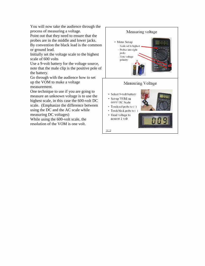
You will now take the audience through the
process of measuring a voltage. Point out that they need to ensure that the
probes are in the middle and lower jacks.
By convention the black lead is the common
or ground lead.
Initially set the voltage scale to the highest
scale of 600 volts
Use a 9-volt battery for the voltage source,
note that the male clip is the positive pole of
the battery.
Go through with the audience how to set
up the VOM to make a voltage
measurement. One technique to use if you are going to
measure an unknown voltage is to use the
highest scale, in this case the 600-volt DC
scale. (Emphasize the difference between
using the DC and the AC scale while
measuring DC voltages)
While using the 600-volt scale, the
resolution of the VOM is one volt.

The purpose of this exercise is to show
that the VOM can tell the difference
between negative and positive voltages.
Point out to the audience that some
VOMs, particularly analogue types will
not be as forgiving, that putting the probes
on reverse voltages can damage the
meters.
Using a voltage scale that is closer to the
actual voltage shows an improvement in
resolution, in this case the voltage value is
to one decimal place or 1/10th of a volt.
Again, using a scale a little closer to the
actual voltage results in additional
resolution, this time to 1/100th
of a volt.
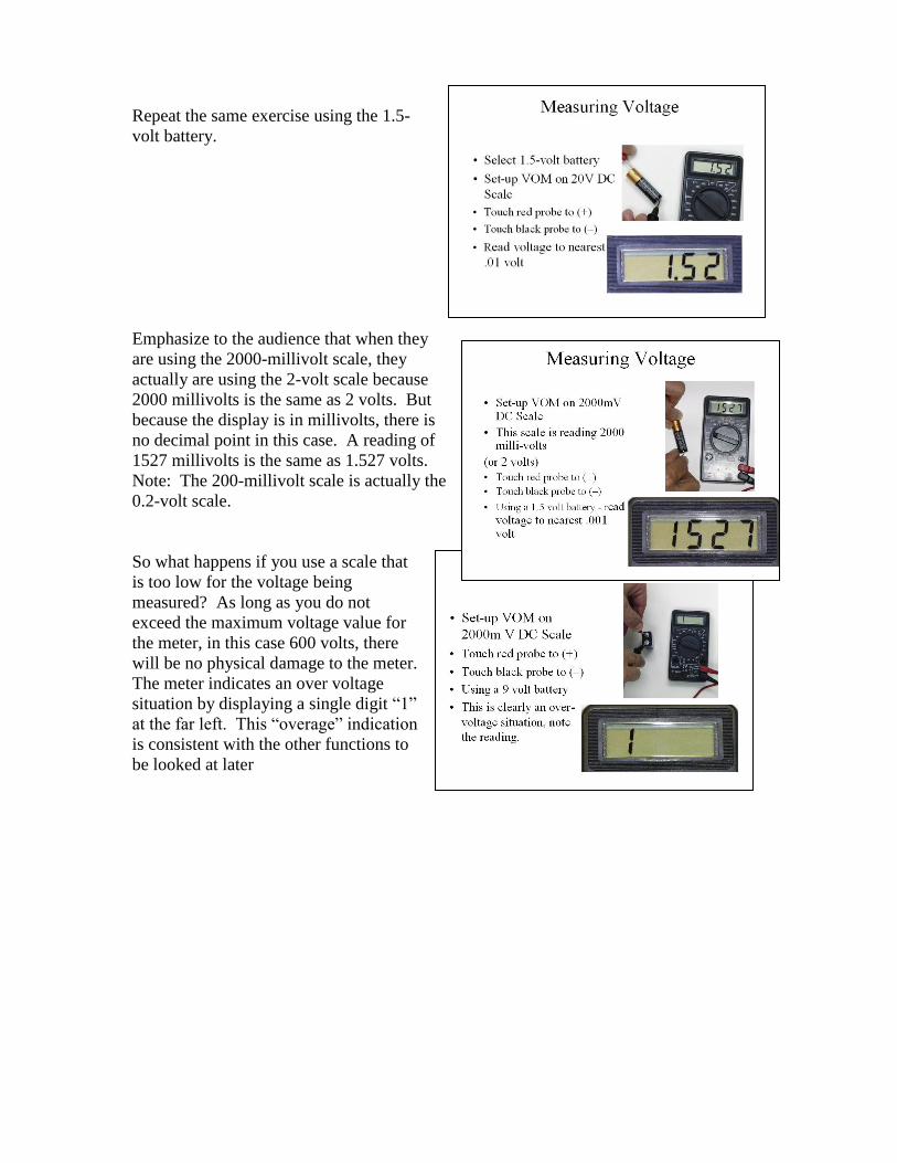
Repeat the same exercise using the 1.5-
volt battery.
Emphasize to the audience that when they
are using the 2000-millivolt scale, they
actually are using the 2-volt scale because
2000 millivolts is the same as 2 volts. But
because the display is in millivolts, there is
no decimal point in this case. A reading of
1527 millivolts is the same as 1.527 volts. Note: The 200-millivolt scale is actually the
0.2-volt scale.
So what happens if you use a scale that
is too low for the voltage being
measured? As long as you do not
exceed the maximum voltage value for
the meter, in this case 600 volts, there
will be no physical damage to the meter.
The meter indicates an over voltage
situation by displaying a single digit “1”
at the far left. This “overage” indication
is consistent with the other functions to
be looked at later
Spend some time with the audience
discussing safety considerations
particularly when working around high
voltages and high currents. The operators
of the voltmeter could be exposed to lethal
voltage and current levels. Also when
probing a live circuit, careless cross
contacts and the resulting short circuits
could route equipment damaging levels of
voltage and current to the circuit under
test. Personal experiences will help
illustrate the point. A good technique is the do a “dry run” of probe placement with power turned off.
During the dry run, the operator can see if the probe placement is correct and not short-
circuiting to damaging voltages and currents. Practice probe placements, and once
confidant, turn on the power source to make the measurement.
Another good technique is to start all measurements at the highest range and then adjust
the range downward to the appropriate level. There are usually automatic protection
features in VOMs, but it is best not to consistently depend on them doing their intended
jobs.
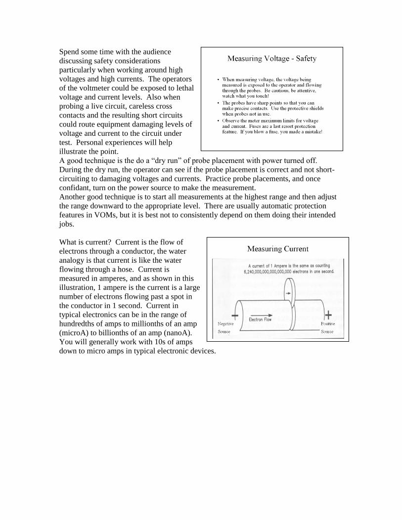
What is current? Current is the flow of
electrons through a conductor, the water
analogy is that current is like the water
flowing through a hose. Current is
measured in amperes, and as shown in this
illustration, 1 ampere is the current is a large
number of electrons flowing past a spot in
the conductor in 1 second. Current in
typical electronics can be in the range of
hundredths of amps to millionths of an amp
(microA) to billionths of an amp (nanoA).
You will generally work with 10s of amps
down to micro amps in typical electronic devices.

Continue your discussion of safety, particularly
equipment safety, when measuring current. Re-emphasize the difference between AC and
DC voltages and currents.
Finally, spend some time to amplify the final
bullet. To measure current, the current must
flow through the meter as opposed to measuring
voltage when it was only necessary to sample
the voltage surrounding the source (or
component of interest). Generally, to have the
current flow through the VOM, an existing
circuit must be broken (i.e., un-soldered) and
the meter probes connected to either side of the “break.” The VOM then becomes part of
the path through which the current must flow.
While the audience is looking at the VOM,
point out the two current scales and the
associate probe jacks. In most situations the
user will use the center jack and the low current
scale. There may be rare occasions when higher
than 200 milliamps will be measured. This will
require switching the probe jack along with
selecting the high current range on the meter. In the event of an over current situation, the
internal fuse will blow. To return the VOM to
operation, the fuse must be replaced, with the
same size fuse, by opening the VOM case and
replacing the fuse. If the user is going to be making frequent current measurements,
particularly in high current situations, it is advisable to have spare fuses handy at the
workbench.
This might be a good time to talk about how fuses operate and the cautions surrounding
replacing fuses (use the same current rated fuse as the one blown). Demonstrate
replacing one in the meter.
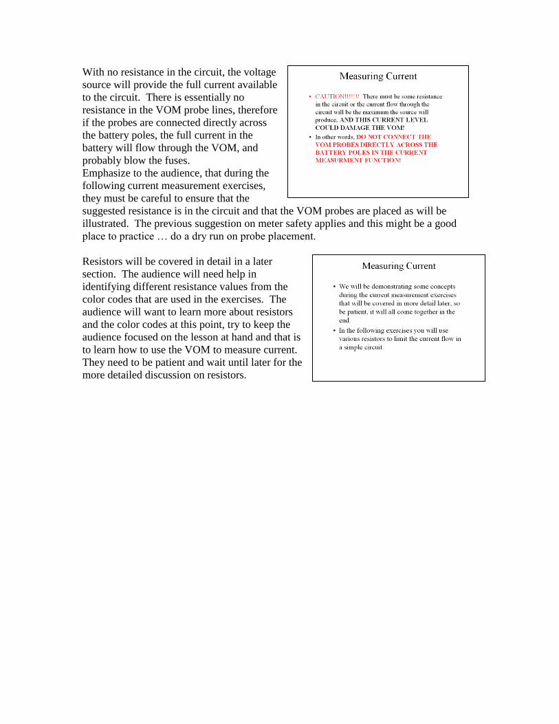
With no resistance in the circuit, the voltage
source will provide the full current available
to the circuit. There is essentially no
resistance in the VOM probe lines, therefore
if the probes are connected directly across
the battery poles, the full current in the
battery will flow through the VOM, and
probably blow the fuses. Emphasize to the audience, that during the
following current measurement exercises,
they must be careful to ensure that the
suggested resistance is in the circuit and that the VOM probes are placed as will be
illustrated. The previous suggestion on meter safety applies and this might be a good
place to practice … do a dry run on probe placement.
Resistors will be covered in detail in a later
section. The audience will need help in
identifying different resistance values from the
color codes that are used in the exercises. The
audience will want to learn more about resistors
and the color codes at this point, try to keep the
audience focused on the lesson at hand and that is
to learn how to use the VOM to measure current.
They need to be patient and wait until later for the
more detailed discussion on resistors.
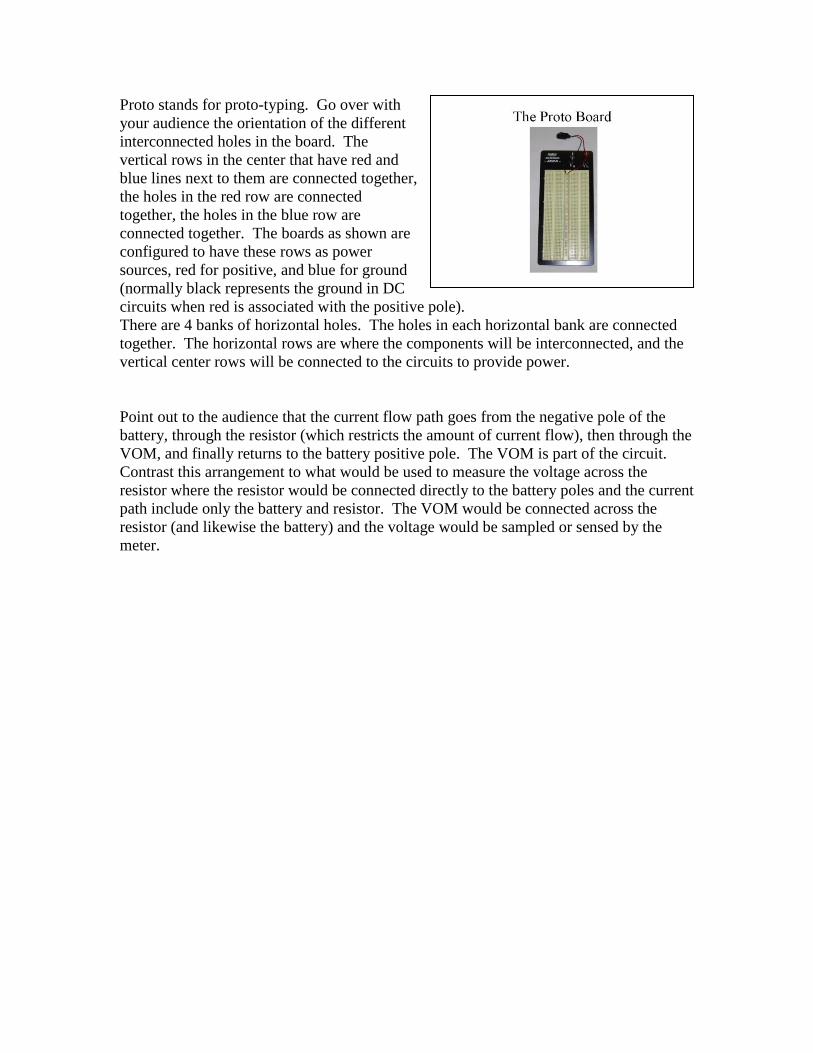
Proto stands for proto-typing. Go over with
your audience the orientation of the different
interconnected holes in the board. The
vertical rows in the center that have red and
blue lines next to them are connected together,
the holes in the red row are connected
together, the holes in the blue row are
connected together. The boards as shown are
configured to have these rows as power
sources, red for positive, and blue for ground
(normally black represents the ground in DC
circuits when red is associated with the positive pole). There are 4 banks of horizontal holes. The holes in each horizontal bank are connected
together. The horizontal rows are where the components will be interconnected, and the
vertical center rows will be connected to the circuits to provide power.
Point out to the audience that the current flow path goes from the negative pole of the
battery, through the resistor (which restricts the amount of current flow), then through the
VOM, and finally returns to the battery positive pole. The VOM is part of the circuit. Contrast this arrangement to what would be used to measure the voltage across the
resistor where the resistor would be connected directly to the battery poles and the current
path include only the battery and resistor. The VOM would be connected across the
resistor (and likewise the battery) and the voltage would be sampled or sensed by the
meter.
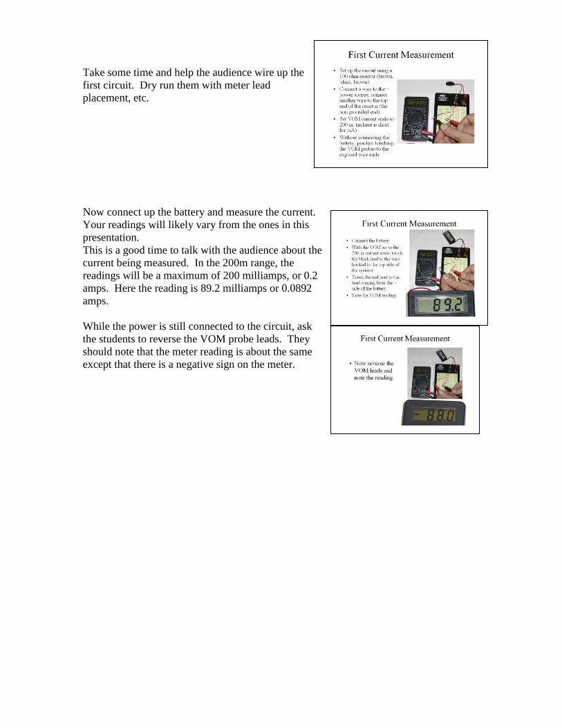
Take some time and help the audience wire up the
first circuit. Dry run them with meter lead
placement, etc.
Now connect up the battery and measure the current.
Your readings will likely vary from the ones in this
presentation. This is a good time to talk with the audience about the
current being measured. In the 200m range, the
readings will be a maximum of 200 milliamps, or 0.2
amps. Here the reading is 89.2 milliamps or 0.0892
amps.
While the power is still connected to the circuit, ask
the students to reverse the VOM probe leads. They
should note that the meter reading is about the same
except that there is a negative sign on the meter.
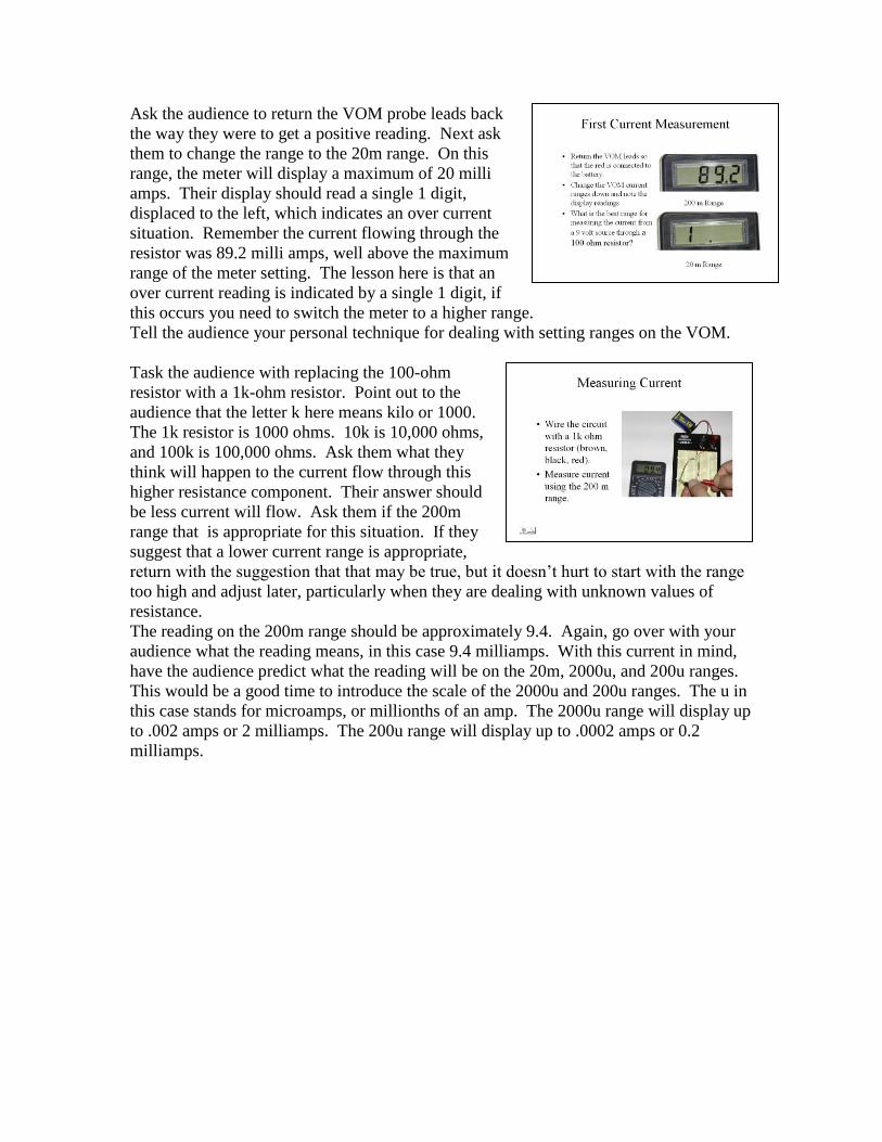
Ask the audience to return the VOM probe leads back
the way they were to get a positive reading. Next ask
them to change the range to the 20m range. On this
range, the meter will display a maximum of 20 milli
amps. Their display should read a single 1 digit,
displaced to the left, which indicates an over current
situation. Remember the current flowing through the
resistor was 89.2 milli amps, well above the maximum
range of the meter setting. The lesson here is that an
over current reading is indicated by a single 1 digit, if
this occurs you need to switch the meter to a higher range. Tell the audience your personal technique for dealing with setting ranges on the VOM.
Task the audience with replacing the 100-ohm
resistor with a 1k-ohm resistor. Point out to the
audience that the letter k here means kilo or 1000.
The 1k resistor is 1000 ohms. 10k is 10,000 ohms,
and 100k is 100,000 ohms. Ask them what they
think will happen to the current flow through this
higher resistance component. Their answer should
be less current will flow. Ask them if the 200m
range that is appropriate for this situation. If they
suggest that a lower current range is appropriate,
return with the suggestion that that may be true, but it doesn’t hurt to start with the range
too high and adjust later, particularly when they are dealing with unknown values of
resistance. The reading on the 200m range should be approximately 9.4. Again, go over with your
audience what the reading means, in this case 9.4 milliamps. With this current in mind,
have the audience predict what the reading will be on the 20m, 2000u, and 200u ranges.
This would be a good time to introduce the scale of the 2000u and 200u ranges. The u in
this case stands for microamps, or millionths of an amp. The 2000u range will display up
to .002 amps or 2 milliamps. The 200u range will display up to .0002 amps or 0.2
milliamps.
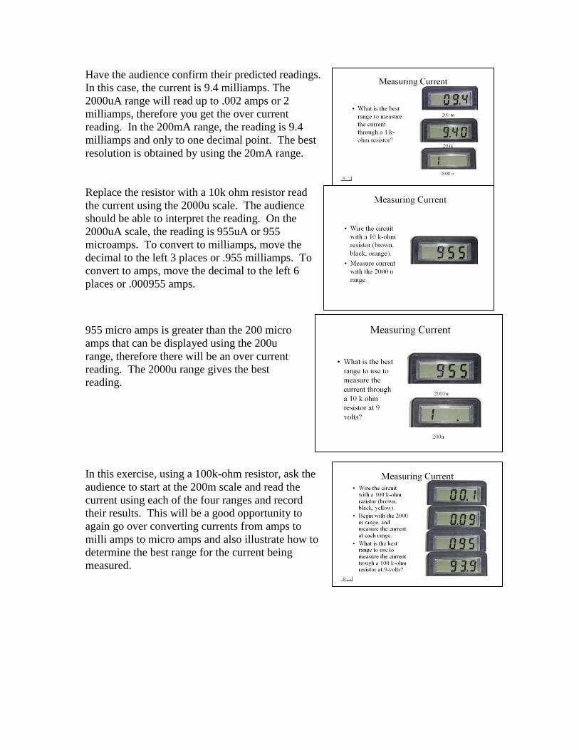
Have the audience confirm their predicted readings.
In this case, the current is 9.4 milliamps. The
2000uA range will read up to .002 amps or 2
milliamps, therefore you get the over current
reading. In the 200mA range, the reading is 9.4
milliamps and only to one decimal point. The best
resolution is obtained by using the 20mA range.
Replace the resistor with a 10k ohm resistor read
the current using the 2000u scale. The audience
should be able to interpret the reading. On the
2000uA scale, the reading is 955uA or 955
microamps. To convert to milliamps, move the
decimal to the left 3 places or .955 milliamps. To
convert to amps, move the decimal to the left 6
places or .000955 amps.
955 micro amps is greater than the 200 micro
amps that can be displayed using the 200u
range, therefore there will be an over current
reading. The 2000u range gives the best
reading.
In this exercise, using a 100k-ohm resistor, ask the
audience to start at the 200m scale and read the
current using each of the four ranges and record
their results. This will be a good opportunity to
again go over converting currents from amps to
milli amps to micro amps and also illustrate how to
determine the best range for the current being
measured.
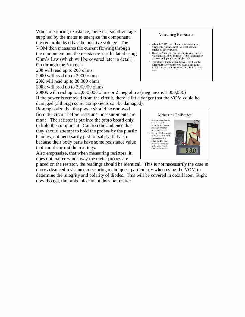
When measuring resistance, there is a small voltage
supplied by the meter to energize the component,
the red probe lead has the positive voltage. The
VOM then measures the current flowing through
the component and the resistance is calculated using
Ohm’s Law (which will be covered later in detail). Go through the 5 ranges.
200 will read up to 200 ohms
2000 will read up to 2000 ohms
20K will read up to 20,000 ohms
200k will read up to 200,000 ohms
2000k will read up to 2,000,000 ohms or 2 meg ohms (meg means 1,000,000)
If the power is removed from the circuit, there is little danger that the VOM could be
damaged (although some components can be damaged).
Re-emphasize that the power should be removed
from the circuit before resistance measurements are
made. The resistor is put into the proto board only
to hold the component. Caution the audience that
they should attempt to hold the probes by the plastic
handles, not necessarily just for safety, but also
because their body parts have some resistance value
that could corrupt the readings. Also emphasize, that when measuring resistors, it
does not matter which way the meter probes are
placed on the resistor, the readings should be identical. This is not necessarily the case in
more advanced resistance measuring techniques, particularly when using the VOM to
determine the integrity and polarity of diodes. This will be covered in detail later. Right
now though, the probe placement does not matter.

There should be no difference in the readings.
Point out to the audience, that by going to higher
ranges, the decimal point of the reading moves to the
left, and eventually goes so far to the left that
resistance is not displayed. The resistance is still 100
ohms; it is just below the threshold of the display. Using the 200 range will result in an over resistance
indication, a single digit 1. Point out to the audience
that over anything on this meter is indicated by a
single digit 1. The most appropriate range to measure 1000 ohms is
the 2000 range. The other higher ranges work, but
the resolution decreases as the decimal point is moved
to the left.
The audience by now should have a pretty good idea
of how to measure resistances. Use this as an
opportunity to fine-tune their skill.

This can be a fun activity. Suggest some
measurements the audience might make, but leave
the majority of the measurement techniques up to
them. Some suggestions:
Probes across individual fingers. 1.8 meg
Probes held between thumb and finger, one in each
hand. 1.4 meg
Probes from the skin on the ankle and skin on hand.
Off scale
Dry skin versus moist skin. Dry 1 meg, moist 96k
Lightly touching ht probes compared to a firmer grasp on the probes. Light 1 meg, firm
300k
The point here is that body contact with the probes during measurements can influence
the ohmmeter reading and should be avoided, particularly when measuring high values of
resistance. You can bring this up again later when you are covering parallel and series
resistance.
The audience probably has observed that trying to
build up a circuit using a picture or words can be
difficult and confusing … and they have only been
dealing with at most one component, one
current/voltage source, and one meter. A better way
to communicate how a circuit is put together is to use
circuit diagrams. There are many, many diagram symbols used to
symbolize the various electronic components. There
are minor variations in the individual symbols to represent variations within a component
class. The following discussion is only an introduction intended to give the audience a
basic working knowledge of circuit diagrams.
Circuit diagrams are road maps that show the pathways that current can take from the
current/voltage source, through the individual components of the circuit to accomplish
some task, and return to the current/voltage source to complete the circuit.
The diagram symbols that will be covered are listed in the slide. The audience may not
know what each of the component does yet, but their individual functions will be covered
later in the course.

This is a simple example of a circuit diagram. In
this case, the circuit decodes the signals sent by a
TV remote control and turns on and off electrical
relay switches in response to the keys pressed on
the TV remote. Point out to the audience that the diagrams they
will be working with are very simple.
The symbol on the left is for a fixed value of
resistance. The symbol on the right shows a pointer that can be moved across the resistor
to vary the resistance. Point out to the audience that they use variable resistors all the
time … volume controls on audio equipment. Generally, a symbol with a pointed arrow associated with it represent variable (or
changeable) components.

Grounding though at first appearances is a simple
topic; it really does have some subtle differences
as represented by these two symbols for ground. A ground is a common return path to the current
in a circuit to the voltage/current source. By
convention, the ground connection is hooked to
the negative pole of the power source. Usually in
reality, the ground is the originating source of
electrons. This seems to be backwards, but that is
the standard convention. In the early days of
automobiles, the positive side of the battery and other voltage/current sources were
connected to ground, that is not true today.
The term grounding probably comes from the safety term related to connecting an
electronic device to a metal rod driven into the earth to provide a safety path for stray
current to flow into the earth and not through the operator’s body. For instance, many
high structures have lightening rods that are hooked to grounding rods driven into the
earth so that in the event of a lightening strike, the dangerous currents from the lightening
strike flow harmlessly into the earth and not through humans in the vicinity.
There are two basic types of grounds as represented by the two symbols. The symbol on
the left, that looks like a shovel, represents a ground connection to an earth ground.
Usually there is only one connection between an electrical device and an earth ground,
and that connection is primarily for safety (this could be argued that the earth ground is
also important for proper RF performance, but that discussion can be done in more
advanced courses).
The symbol on the right, that looks like a rake or pitchfork, represents a chassis ground.
A chassis is the metal box or foundation that the electronic device is contained in. The
symbol actually represents multiple connections between components and the chassis.
The chassis ground is used to provide the common path for current to flow back to the
power source to complete the circuit.
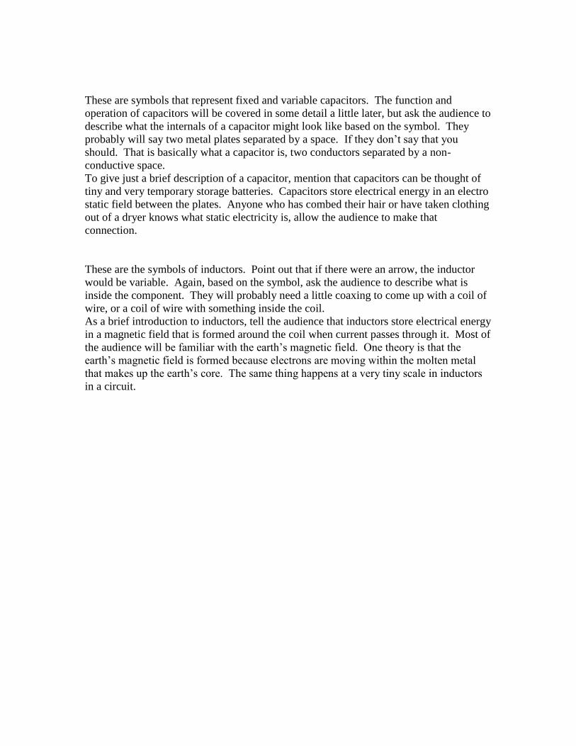
These are symbols that represent fixed and variable capacitors. The function and
operation of capacitors will be covered in some detail a little later, but ask the audience to
describe what the internals of a capacitor might look like based on the symbol. They
probably will say two metal plates separated by a space. If they don’t say that you
should. That is basically what a capacitor is, two conductors separated by a non-
conductive space. To give just a brief description of a capacitor, mention that capacitors can be thought of
tiny and very temporary storage batteries. Capacitors store electrical energy in an electro
static field between the plates. Anyone who has combed their hair or have taken clothing
out of a dryer knows what static electricity is, allow the audience to make that
connection.
These are the symbols of inductors. Point out that if there were an arrow, the inductor
would be variable. Again, based on the symbol, ask the audience to describe what is
inside the component. They will probably need a little coaxing to come up with a coil of
wire, or a coil of wire with something inside the coil. As a brief introduction to inductors, tell the audience that inductors store electrical energy
in a magnetic field that is formed around the coil when current passes through it. Most of
the audience will be familiar with the earth’s magnetic field. One theory is that the
earth’s magnetic field is formed because electrons are moving within the molten metal
that makes up the earth’s core. The same thing happens at a very tiny scale in inductors
in a circuit.
There are numerous types of diodes for various purposes. Describe to the audience what
each symbol represents. The regular diode, the zener diode, and light emitting diode.
A trick to help the audience to identify the types of bipolar transistors is to look at the
direction of the arrow. If the arrow is pointing out, it is Not Pointing iN, that is an NPN
transistor. If the arrow is pointing in, it is Pointing iN Proudly, that is a PNP transistor.
On the FET, the direction of the arrow identifies the material of the junction, in the
illustration the arrow is not pointing in; therefore this represents a P junction FET.
By their very nature, integrated circuits are a collection of components that together
perform a function. It is not necessary to know what goes on inside the IC, just how the
IC interfaces with the rest of the circuit. Therefore the symbol provides only information
on which pin of the IC is connected to the surrounding components. Sometimes there is a
descriptive label on a pin, for instance GND for ground, and Vcc for the power source.
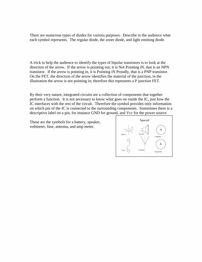
These are the symbols for a battery, speaker,
voltmeter, fuse, antenna, and amp meter.
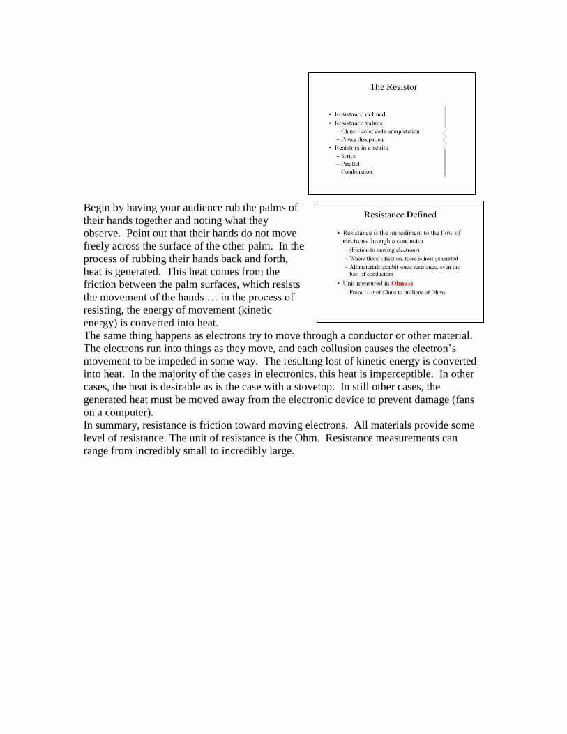
Begin by having your audience rub the palms of
their hands together and noting what they
observe. Point out that their hands do not move
freely across the surface of the other palm. In the
process of rubbing their hands back and forth,
heat is generated. This heat comes from the
friction between the palm surfaces, which resists
the movement of the hands … in the process of
resisting, the energy of movement (kinetic
energy) is converted into heat. The same thing happens as electrons try to move through a conductor or other material.
The electrons run into things as they move, and each collusion causes the electron’s
movement to be impeded in some way. The resulting lost of kinetic energy is converted
into heat. In the majority of the cases in electronics, this heat is imperceptible. In other
cases, the heat is desirable as is the case with a stovetop. In still other cases, the
generated heat must be moved away from the electronic device to prevent damage (fans
on a computer).
In summary, resistance is friction toward moving electrons. All materials provide some
level of resistance. The unit of resistance is the Ohm. Resistance measurements can
range from incredibly small to incredibly large.
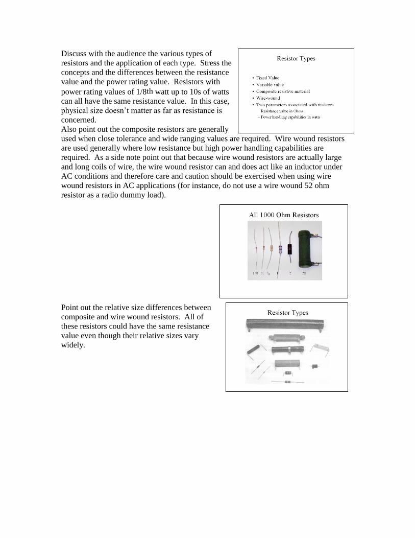
Discuss with the audience the various types of
resistors and the application of each type. Stress the
concepts and the differences between the resistance
value and the power rating value. Resistors with
power rating values of 1/8th watt up to 10s of watts
can all have the same resistance value. In this case,
physical size doesn’t matter as far as resistance is
concerned. Also point out the composite resistors are generally
used when close tolerance and wide ranging values are required. Wire wound resistors
are used generally where low resistance but high power handling capabilities are
required. As a side note point out that because wire wound resistors are actually large
and long coils of wire, the wire wound resistor can and does act like an inductor under
AC conditions and therefore care and caution should be exercised when using wire
wound resistors in AC applications (for instance, do not use a wire wound 52 ohm
resistor as a radio dummy load).
Point out the relative size differences between
composite and wire wound resistors. All of
these resistors could have the same resistance
value even though their relative sizes vary
widely.
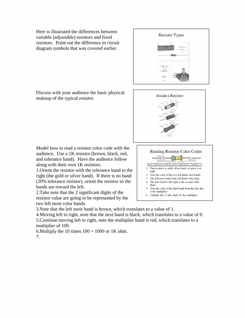
Here is illustrated the differences between
variable (adjustable) resistors and fixed
resistors. Point out the difference in circuit
diagram symbols that was covered earlier.
Discuss with your audience the basic physical
makeup of the typical resistor.
Model how to read a resistor color code with the
audience. Use a 1K resistor (brown, black, red,
and tolerance band). Have the audience follow
along with their own 1K resistors. 1.Orient the resistor with the tolerance band to the
right (the gold or silver band). If there is no band
(20% tolerance resistor), orient the resistor so the
bands are toward the left.
2.Take note that the 2 significant digits of the
resistor value are going to be represented by the
two left most color bands.
3.Note that the left most band is brown, which translates to a value of 1.
4.Moving left to right, note that the next band is black, which translates to a value of 0.
5.Continue moving left to right, note the multiplier band is red, which translates to a
multiplier of 100.
6.Multiply the 10 times 100 = 1000 or 1K ohm.
7.
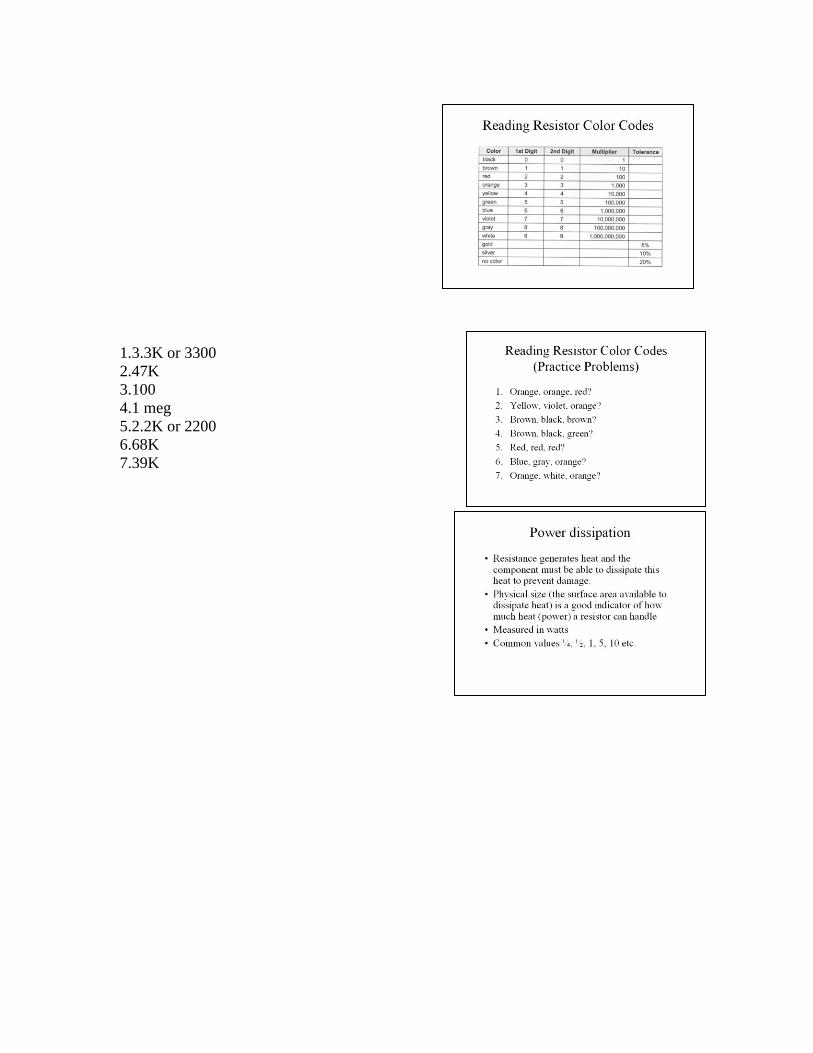
1.3.3K or 3300 2.47K
3.100
4.1 meg
5.2.2K or 2200
6.68K
7.39K
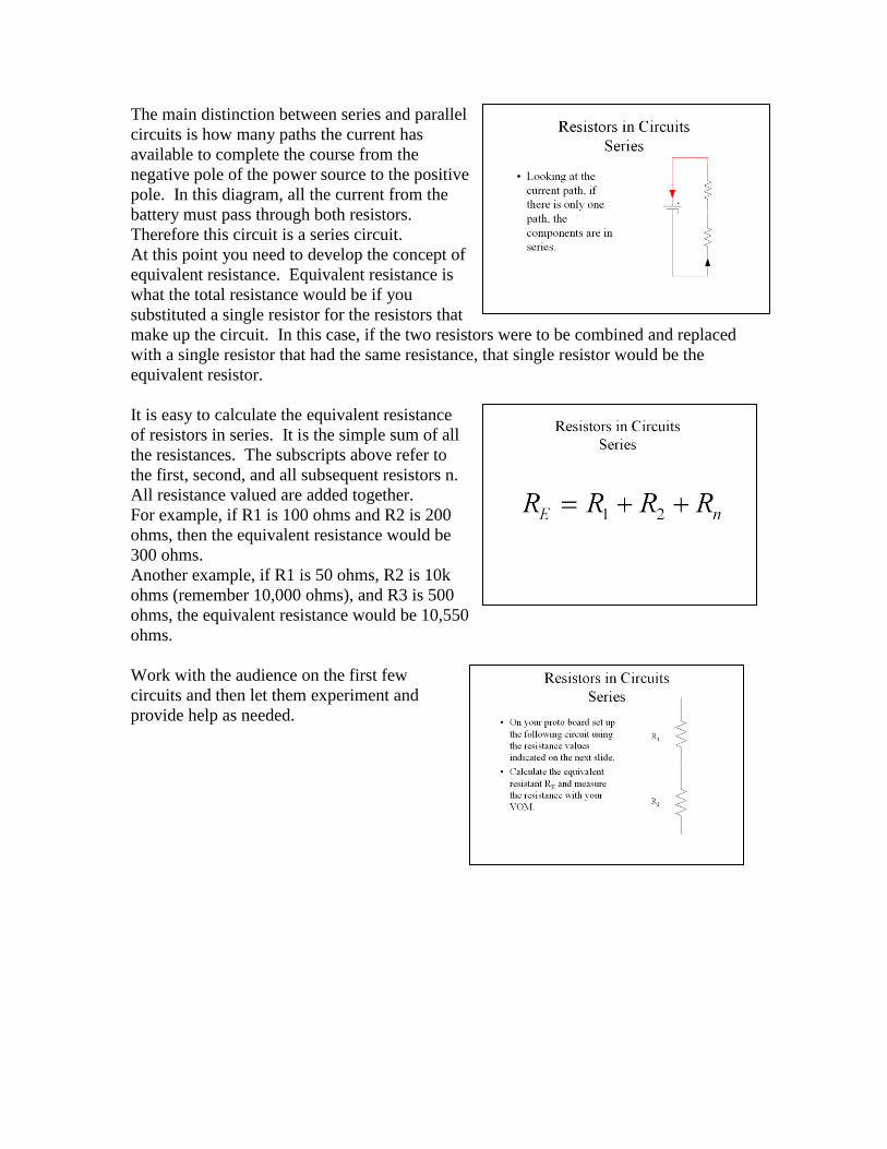
The main distinction between series and parallel
circuits is how many paths the current has
available to complete the course from the
negative pole of the power source to the positive
pole. In this diagram, all the current from the
battery must pass through both resistors.
Therefore this circuit is a series circuit. At this point you need to develop the concept of
equivalent resistance. Equivalent resistance is
what the total resistance would be if you
substituted a single resistor for the resistors that
make up the circuit. In this case, if the two resistors were to be combined and replaced
with a single resistor that had the same resistance, that single resistor would be the
equivalent resistor.
It is easy to calculate the equivalent resistance
of resistors in series. It is the simple sum of all
the resistances. The subscripts above refer to
the first, second, and all subsequent resistors n.
All resistance valued are added together. For example, if R1 is 100 ohms and R2 is 200
ohms, then the equivalent resistance would be
300 ohms.
Another example, if R1 is 50 ohms, R2 is 10k
ohms (remember 10,000 ohms), and R3 is 500
ohms, the equivalent resistance would be 10,550
ohms.
Work with the audience on the first few
circuits and then let them experiment and
provide help as needed.
100 + 100 = 200 100K + 10K = 110K or 100,000 + 10,000=
110,000
4.7K + 4.7K = 9.4K or 4,700 + 4,700 = 9,400
330 + 4.7K = 5.03K or 330 + 4,700 = 5,030
The measured resistances should be close to the
calculated values. Depending on the quality of the
resistors, the actual value of the resistor can be
different with a specified tolerance. Common
tolerances are +/-20%, +/-10%, +/- 5%, and +/-1%.
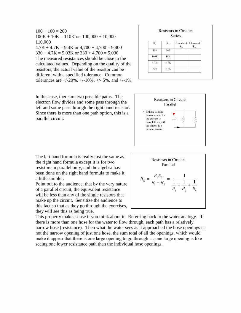
In this case, there are two possible paths. The
electron flow divides and some pass through the
left and some pass through the right hand resistor.
Since there is more than one path option, this is a
parallel circuit.
The left hand formula is really just the same as
the right hand formula except it is for two
resistors in parallel only, and the algebra has
been done on the right hand formula to make it
a little simpler. Point out to the audience, that by the very nature
of a parallel circuit, the equivalent resistance
will be less than any of the single resistors that
make up the circuit. Sensitize the audience to
this fact so that as they go through the exercises,
they will see this as being true.
This property makes sense if you think about it. Referring back to the water analogy. If
there is more than one hose for the water to flow through, each path has a relatively
narrow hose (resistance). Then what the water sees as it approached the hose openings is
not the narrow opening of just one hose, the sum total of all the openings, which would
make it appear that there is one large opening to go through … one large opening is like
seeing one lower resistance path than the individual hose openings.
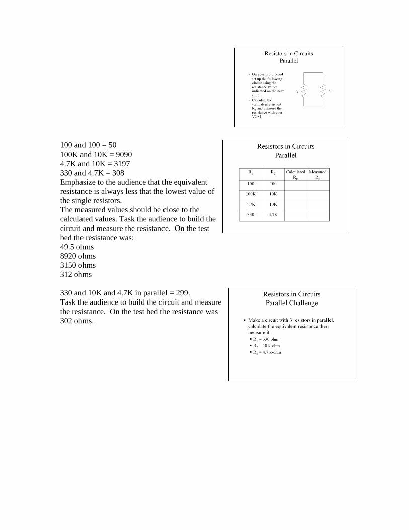
100 and 100 = 50 100K and 10K = 9090
4.7K and 10K = 3197
330 and 4.7K = 308
Emphasize to the audience that the equivalent
resistance is always less that the lowest value of
the single resistors.
The measured values should be close to the
calculated values. Task the audience to build the
circuit and measure the resistance. On the test
bed the resistance was:
49.5 ohms
8920 ohms
3150 ohms
312 ohms
330 and 10K and 4.7K in parallel = 299. Task the audience to build the circuit and measure
the resistance. On the test bed the resistance was
302 ohms.
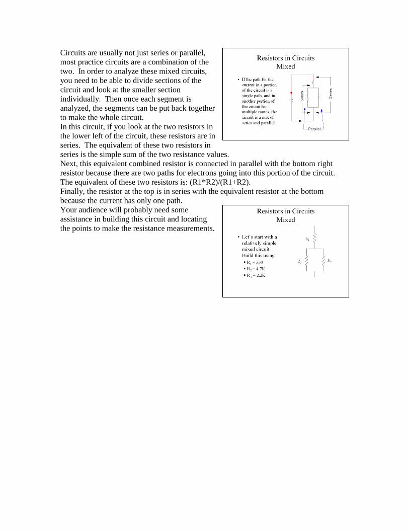
Circuits are usually not just series or parallel,
most practice circuits are a combination of the
two. In order to analyze these mixed circuits,
you need to be able to divide sections of the
circuit and look at the smaller section
individually. Then once each segment is
analyzed, the segments can be put back together
to make the whole circuit. In this circuit, if you look at the two resistors in
the lower left of the circuit, these resistors are in
series. The equivalent of these two resistors in
series is the simple sum of the two resistance values.
Next, this equivalent combined resistor is connected in parallel with the bottom right
resistor because there are two paths for electrons going into this portion of the circuit.
The equivalent of these two resistors is: (R1*R2)/(R1+R2).
Finally, the resistor at the top is in series with the equivalent resistor at the bottom
because the current has only one path.
Your audience will probably need some
assistance in building this circuit and locating
the points to make the resistance measurements.
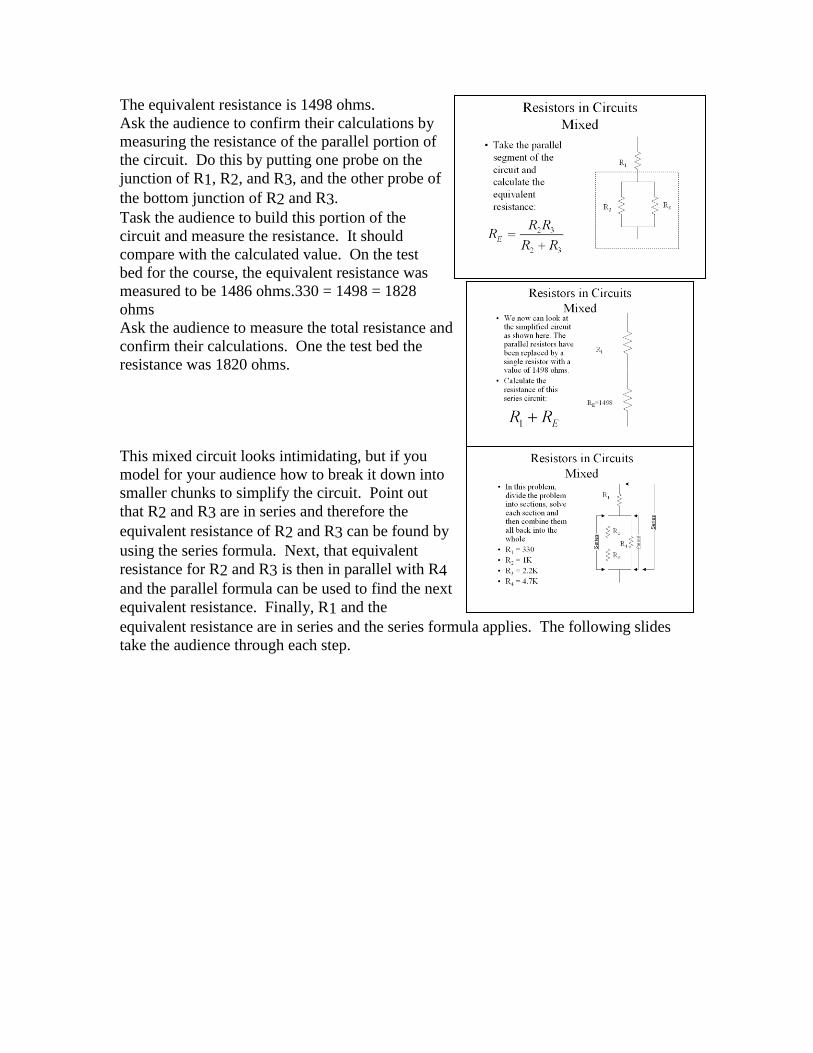
The equivalent resistance is 1498 ohms. Ask the audience to confirm their calculations by
measuring the resistance of the parallel portion of
the circuit. Do this by putting one probe on the
junction of R1, R2, and R3, and the other probe of
the bottom junction of R2 and R3.
Task the audience to build this portion of the
circuit and measure the resistance. It should
compare with the calculated value. On the test
bed for the course, the equivalent resistance was
measured to be 1486 ohms.330 = 1498 = 1828
ohms Ask the audience to measure the total resistance and
confirm their calculations. One the test bed the
resistance was 1820 ohms.
This mixed circuit looks intimidating, but if you
model for your audience how to break it down into
smaller chunks to simplify the circuit. Point out
that R2 and R3 are in series and therefore the
equivalent resistance of R2 and R3 can be found by
using the series formula. Next, that equivalent
resistance for R2 and R3 is then in parallel with R4
and the parallel formula can be used to find the next
equivalent resistance. Finally, R1 and the
equivalent resistance are in series and the series formula applies. The following slides
take the audience through each step.

The equivalent resistance of these two resistors in
series is the sum of the resistances. RE = 3.2K =
3,200 ohms The measured resistance on the test bed was 3,170
ohms.
It is helpful if the audience redraws the circuit on
a scrap piece of paper so they can keep track of
the substitutions. Now that the equivalent
resistance has been found for the series pair R2 and
R3, the equivalent resistance is placed in the circuit.
The next step is to simplify the parallel resistor RE
and R4.
Solving this parallel portion of the circuit RE =
1.9K. The measured resistance on the test bed was 1,880
ohms.
The circuit can now be further simplified by
substituting the equivalent resistance just calculated
in for the parallel portion of the circuit. The final
calculation involves now only two resistors in
series, R1 and RE.
The final resistance is 2,230 ohms.
The measured resistance on the test bed was 2,220
ohms.
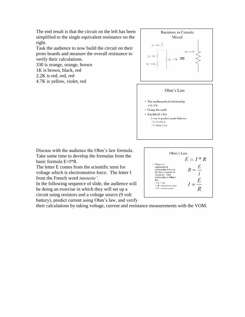
The end result is that the circuit on the left has been
simplified to the single equivalent resistance on the
right. Task the audience to now build the circuit on their
proto boards and measure the overall resistance to
verify their calculations.
330 is orange, orange, brown
1K is brown, black, red
2.2K is red, red, red
4.7K is yellow, violet, red
Discuss with the audience the Ohm’s law formula.
Take some time to develop the formulas from the
basic formula E=I*R. The letter E comes from the scientific term for
voltage which is electromotive force. The letter I
from the French word intensite’.
In the following sequence of slide, the audience will
be doing an exercise in which they will set up a
circuit using resistors and a voltage source (9 volt
battery), predict current using Ohm’s law, and verify
their calculations by taking voltage, current and resistance measurements with the VOM.
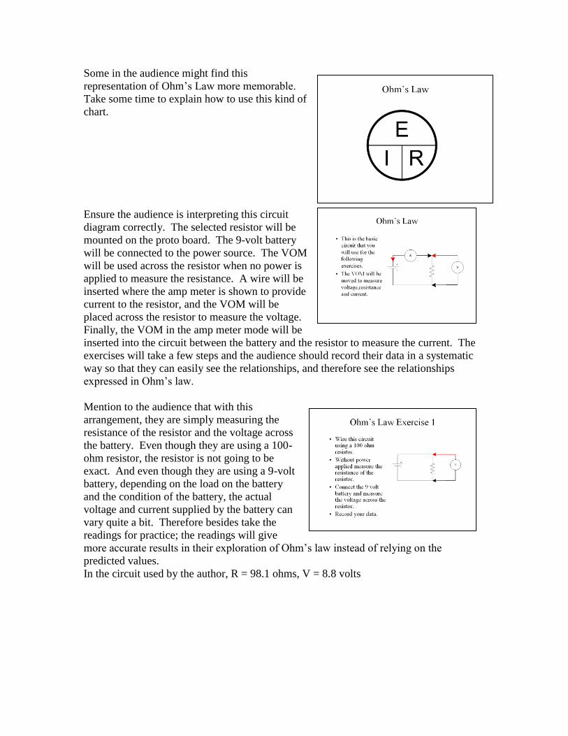
Some in the audience might find this
representation of Ohm’s Law more memorable.
Take some time to explain how to use this kind of
chart.
Ensure the audience is interpreting this circuit
diagram correctly. The selected resistor will be
mounted on the proto board. The 9-volt battery
will be connected to the power source. The VOM
will be used across the resistor when no power is
applied to measure the resistance. A wire will be
inserted where the amp meter is shown to provide
current to the resistor, and the VOM will be
placed across the resistor to measure the voltage.
Finally, the VOM in the amp meter mode will be
inserted into the circuit between the battery and the resistor to measure the current. The
exercises will take a few steps and the audience should record their data in a systematic
way so that they can easily see the relationships, and therefore see the relationships
expressed in Ohm’s law.
Mention to the audience that with this
arrangement, they are simply measuring the
resistance of the resistor and the voltage across
the battery. Even though they are using a 100-
ohm resistor, the resistor is not going to be
exact. And even though they are using a 9-volt
battery, depending on the load on the battery
and the condition of the battery, the actual
voltage and current supplied by the battery can
vary quite a bit. Therefore besides take the
readings for practice; the readings will give
more accurate results in their exploration of Ohm’s law instead of relying on the
predicted values. In the circuit used by the author, R = 98.1 ohms, V = 8.8 volts
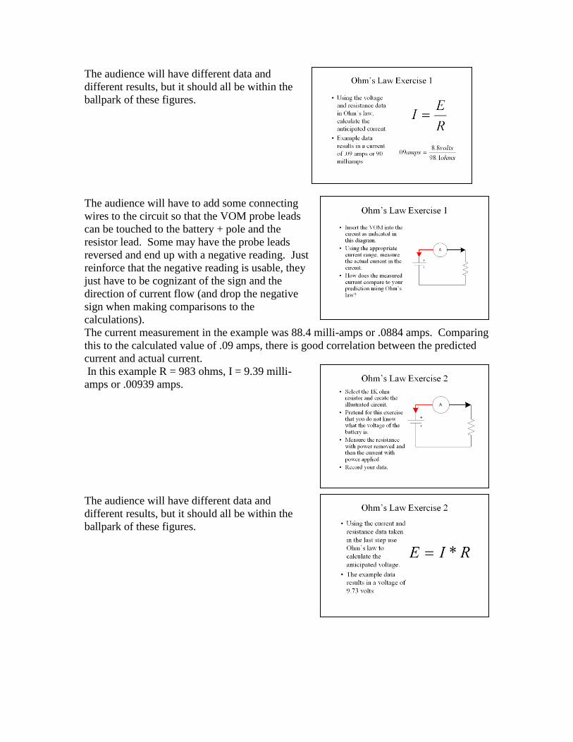
The audience will have different data and
different results, but it should all be within the
ballpark of these figures.
The audience will have to add some connecting
wires to the circuit so that the VOM probe leads
can be touched to the battery + pole and the
resistor lead. Some may have the probe leads
reversed and end up with a negative reading. Just
reinforce that the negative reading is usable, they
just have to be cognizant of the sign and the
direction of current flow (and drop the negative
sign when making comparisons to the
calculations). The current measurement in the example was 88.4 milli-amps or .0884 amps. Comparing
this to the calculated value of .09 amps, there is good correlation between the predicted
current and actual current.
In this example R = 983 ohms, I = 9.39 milli-
amps or .00939 amps.
The audience will have different data and
different results, but it should all be within the
ballpark of these figures.
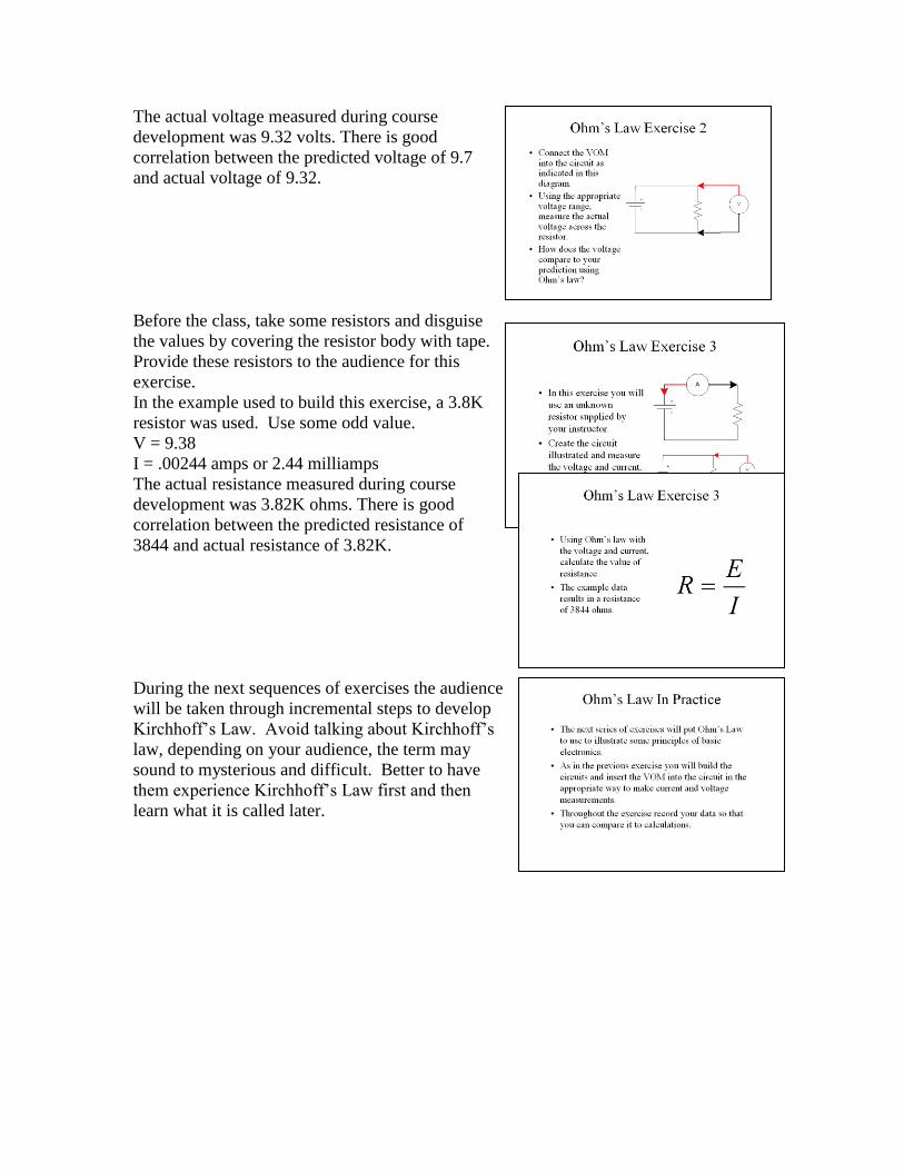
The actual voltage measured during course
development was 9.32 volts. There is good
correlation between the predicted voltage of 9.7
and actual voltage of 9.32.
Before the class, take some resistors and disguise
the values by covering the resistor body with tape.
Provide these resistors to the audience for this
exercise. In the example used to build this exercise, a 3.8K
resistor was used. Use some odd value.
V = 9.38
I = .00244 amps or 2.44 milliamps
The actual resistance measured during course
development was 3.82K ohms. There is good
correlation between the predicted resistance of
3844 and actual resistance of 3.82K.
During the next sequences of exercises the audience
will be taken through incremental steps to develop
Kirchhoff’s Law. Avoid talking about Kirchhoff’s
law, depending on your audience, the term may
sound to mysterious and difficult. Better to have
them experience Kirchhoff’s Law first and then
learn what it is called later.
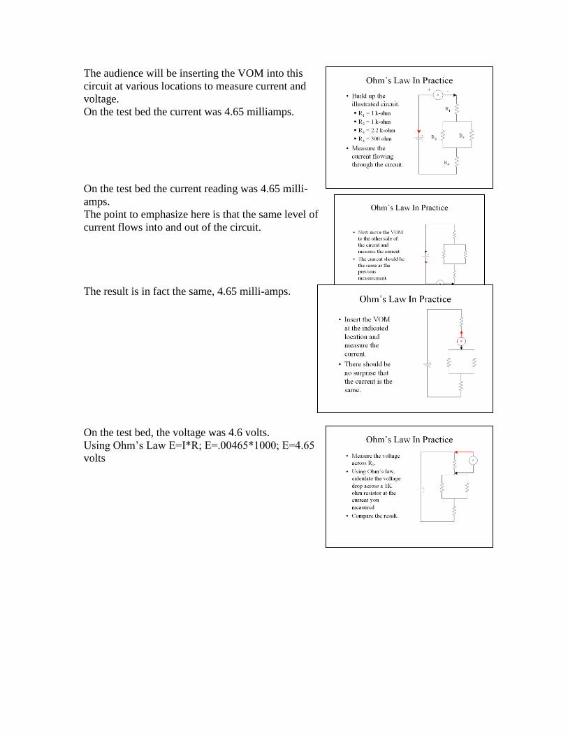
The audience will be inserting the VOM into this
circuit at various locations to measure current and
voltage. On the test bed the current was 4.65 milliamps.
On the test bed the current reading was 4.65 milli-
amps. The point to emphasize here is that the same level of
current flows into and out of the circuit.
The result is in fact the same, 4.65 milli-amps.
On the test bed, the voltage was 4.6 volts. Using Ohm’s Law E=I*R; E=.00465*1000; E=4.65
volts
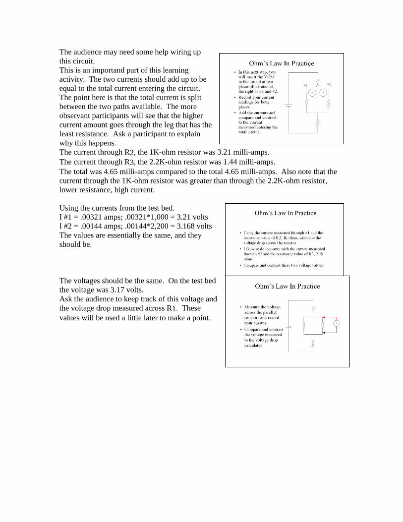
The audience may need some help wiring up
this circuit. This is an importand part of this learning
activity. The two currents should add up to be
equal to the total current entering the circuit.
The point here is that the total current is split
between the two paths available. The more
observant participants will see that the higher
current amount goes through the leg that has the
least resistance. Ask a participant to explain
why this happens.
The current through R2, the 1K-ohm resistor was 3.21 milli-amps.
The current through R3, the 2.2K-ohm resistor was 1.44 milli-amps.
The total was 4.65 milli-amps compared to the total 4.65 milli-amps. Also note that the
current through the 1K-ohm resistor was greater than through the 2.2K-ohm resistor,
lower resistance, high current.
Using the currents from the test bed. I #1 = .00321 amps; .00321*1,000 = 3.21 volts
I #2 = .00144 amps; .00144*2,200 = 3.168 volts
The values are essentially the same, and they
should be.
The voltages should be the same. On the test bed
the voltage was 3.17 volts. Ask the audience to keep track of this voltage and
the voltage drop measured across R1. These
values will be used a little later to make a point.
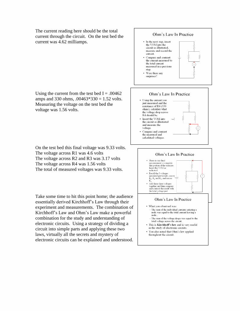
The current reading here should be the total
current through the circuit. On the test bed the
current was 4.62 milliamps.
Using the current from the test bed I = .00462
amps and 330 ohms, .00463*330 = 1.52 volts. Measuring the voltage on the test bed the
voltage was 1.56 volts.
On the test bed this final voltage was 9.33 volts. The voltage across R1 was 4.6 volts
The voltage across R2 and R3 was 3.17 volts
The voltage across R4 was 1.56 volts
The total of measured voltages was 9.33 volts.
Take some time to hit this point home; the audience
essentially derived Kirchhoff’s Law through their
experiment and measurements. The combination of
Kirchhoff’s Law and Ohm’s Law make a powerful
combination for the study and understanding of
electronic circuits. Using a strategy of dividing a
circuit into simple parts and applying these two
laws, virtually all the secrets and mystery of
electronic circuits can be explained and understood.

Emphasize with the audience that you will not be
going into as much detail as you discuss the
remaining basic electronic components. The
purpose of this course is to give a very basic
overview of electronics and a just a basic
understanding of what these components do in a
circuit is part of that understanding. If more
information is desired, additional study materials and in-depth reading is available on the
subject. In this next section you will cover what a capacitor is, what it does, the physical
characteristics that influence the amount of capacitance, and how capacitors react
differently in series and parallel circuits from resistors.
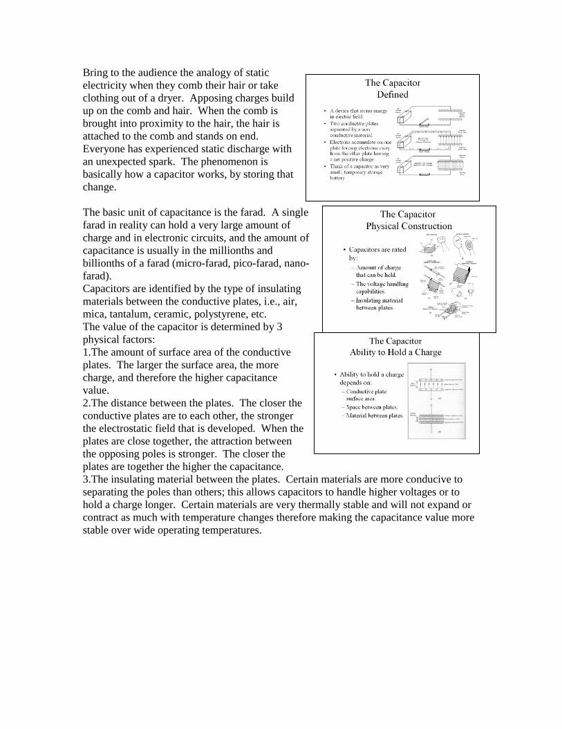
Bring to the audience the analogy of static
electricity when they comb their hair or take
clothing out of a dryer. Apposing charges build
up on the comb and hair. When the comb is
brought into proximity to the hair, the hair is
attached to the comb and stands on end.
Everyone has experienced static discharge with
an unexpected spark. The phenomenon is
basically how a capacitor works, by storing that
change.
The basic unit of capacitance is the farad. A single
farad in reality can hold a very large amount of
charge and in electronic circuits, and the amount of
capacitance is usually in the millionths and
billionths of a farad (micro-farad, pico-farad, nano-
farad). Capacitors are identified by the type of insulating
materials between the conductive plates, i.e., air,
mica, tantalum, ceramic, polystyrene, etc.
The value of the capacitor is determined by 3
physical factors: 1.The amount of surface area of the conductive
plates. The larger the surface area, the more
charge, and therefore the higher capacitance
value.
2.The distance between the plates. The closer the
conductive plates are to each other, the stronger
the electrostatic field that is developed. When the
plates are close together, the attraction between
the opposing poles is stronger. The closer the
plates are together the higher the capacitance.
3.The insulating material between the plates. Certain materials are more conducive to
separating the poles than others; this allows capacitors to handle higher voltages or to
hold a charge longer. Certain materials are very thermally stable and will not expand or
contract as much with temperature changes therefore making the capacitance value more
stable over wide operating temperatures.
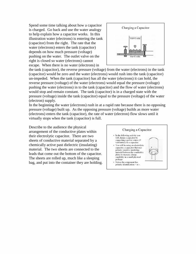
Spend some time talking about how a capacitor
is charged. Go back and use the water analogy
to help explain how a capacitor works. In this
illustration water (electrons) is entering the tank
(capacitor) from the right. The rate that the
water (electrons) enters the tank (capacitor)
depends on how much pressure (voltage)
pushing on the water. The outlet valve on the
right is closed so water (electrons) cannot
escape. When there is no water (electrons) in
the tank (capacitor), the reverse pressure (voltage) from the water (electrons) in the tank
(capacitor) would be zero and the water (electrons) would rush into the tank (capacitor)
un-impeded. When the tank (capacitor) has all the water (electrons) it can hold, the
reverse pressure (voltage) of the water (electrons) would equal the pressure (voltage)
pushing the water (electrons) in to the tank (capacitor) and the flow of water (electrons)
would stop and remain constant. The tank (capacitor) is in a charged state with the
pressure (voltage) inside the tank (capacitor) equal to the pressure (voltage) of the water
(electron) supply. In the beginning the water (electrons) rush in at a rapid rate because there is no opposing
pressure (voltage) built up. As the opposing pressure (voltage) builds as more water
(electrons) enters the tank (capacitor), the rate of water (electron) flow slows until it
virtually stops when the tank (capacitor) is full.
Describe to the audience the physical
arrangement of the conductive plates within
their electrolytic capacitor. There are two
sheets of conductive material separated by a
chemically active past dielectric (insulating)
material. The two sheets are connected to the
leads that come out the bottom of the capacitor.
The sheets are rolled up, much like a sleeping
bag, and put into the container they are holding.
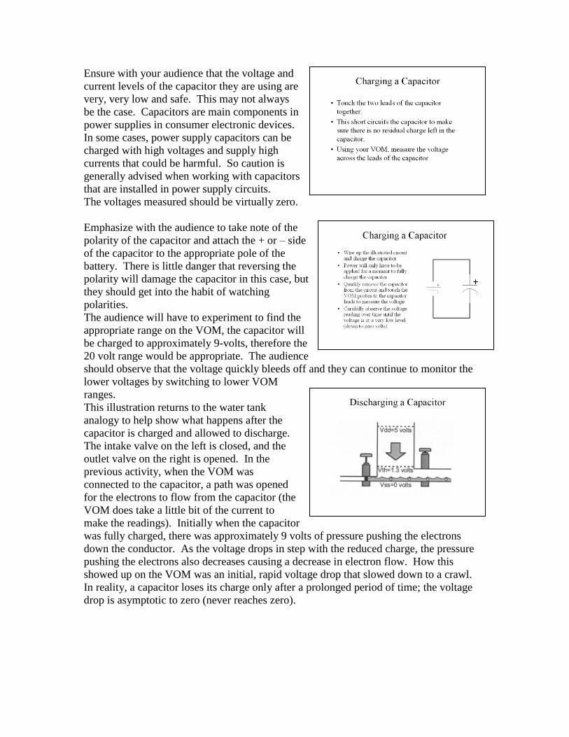
Ensure with your audience that the voltage and
current levels of the capacitor they are using are
very, very low and safe. This may not always
be the case. Capacitors are main components in
power supplies in consumer electronic devices.
In some cases, power supply capacitors can be
charged with high voltages and supply high
currents that could be harmful. So caution is
generally advised when working with capacitors
that are installed in power supply circuits. The voltages measured should be virtually zero.
Emphasize with the audience to take note of the
polarity of the capacitor and attach the + or – side
of the capacitor to the appropriate pole of the
battery. There is little danger that reversing the
polarity will damage the capacitor in this case, but
they should get into the habit of watching
polarities. The audience will have to experiment to find the
appropriate range on the VOM, the capacitor will
be charged to approximately 9-volts, therefore the
20 volt range would be appropriate. The audience
should observe that the voltage quickly bleeds off and they can continue to monitor the
lower voltages by switching to lower VOM
ranges.
This illustration returns to the water tank
analogy to help show what happens after the
capacitor is charged and allowed to discharge.
The intake valve on the left is closed, and the
outlet valve on the right is opened. In the
previous activity, when the VOM was
connected to the capacitor, a path was opened
for the electrons to flow from the capacitor (the
VOM does take a little bit of the current to
make the readings). Initially when the capacitor
was fully charged, there was approximately 9 volts of pressure pushing the electrons
down the conductor. As the voltage drops in step with the reduced charge, the pressure
pushing the electrons also decreases causing a decrease in electron flow. How this
showed up on the VOM was an initial, rapid voltage drop that slowed down to a crawl.
In reality, a capacitor loses its charge only after a prolonged period of time; the voltage
drop is asymptotic to zero (never reaches zero).
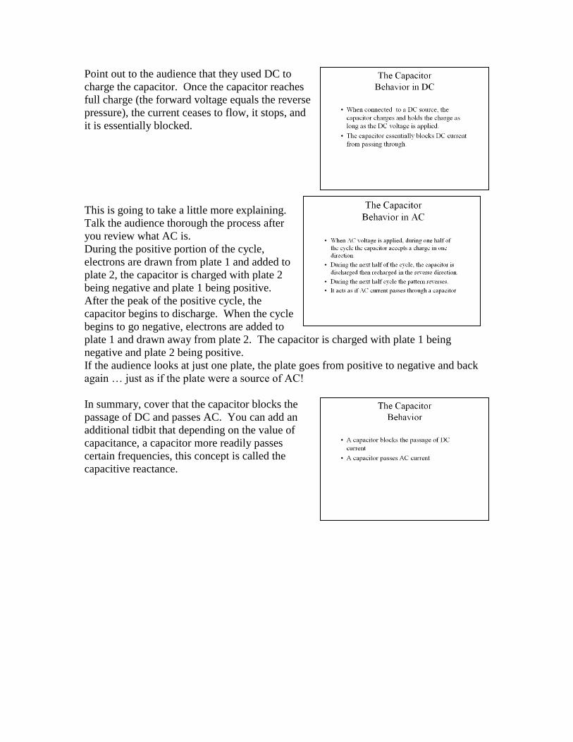
Point out to the audience that they used DC to
charge the capacitor. Once the capacitor reaches
full charge (the forward voltage equals the reverse
pressure), the current ceases to flow, it stops, and
it is essentially blocked.
This is going to take a little more explaining.
Talk the audience thorough the process after
you review what AC is. During the positive portion of the cycle,
electrons are drawn from plate 1 and added to
plate 2, the capacitor is charged with plate 2
being negative and plate 1 being positive.
After the peak of the positive cycle, the
capacitor begins to discharge. When the cycle
begins to go negative, electrons are added to
plate 1 and drawn away from plate 2. The capacitor is charged with plate 1 being
negative and plate 2 being positive.
If the audience looks at just one plate, the plate goes from positive to negative and back
again … just as if the plate were a source of AC!
In summary, cover that the capacitor blocks the
passage of DC and passes AC. You can add an
additional tidbit that depending on the value of
capacitance, a capacitor more readily passes
certain frequencies, this concept is called the
capacitive reactance.
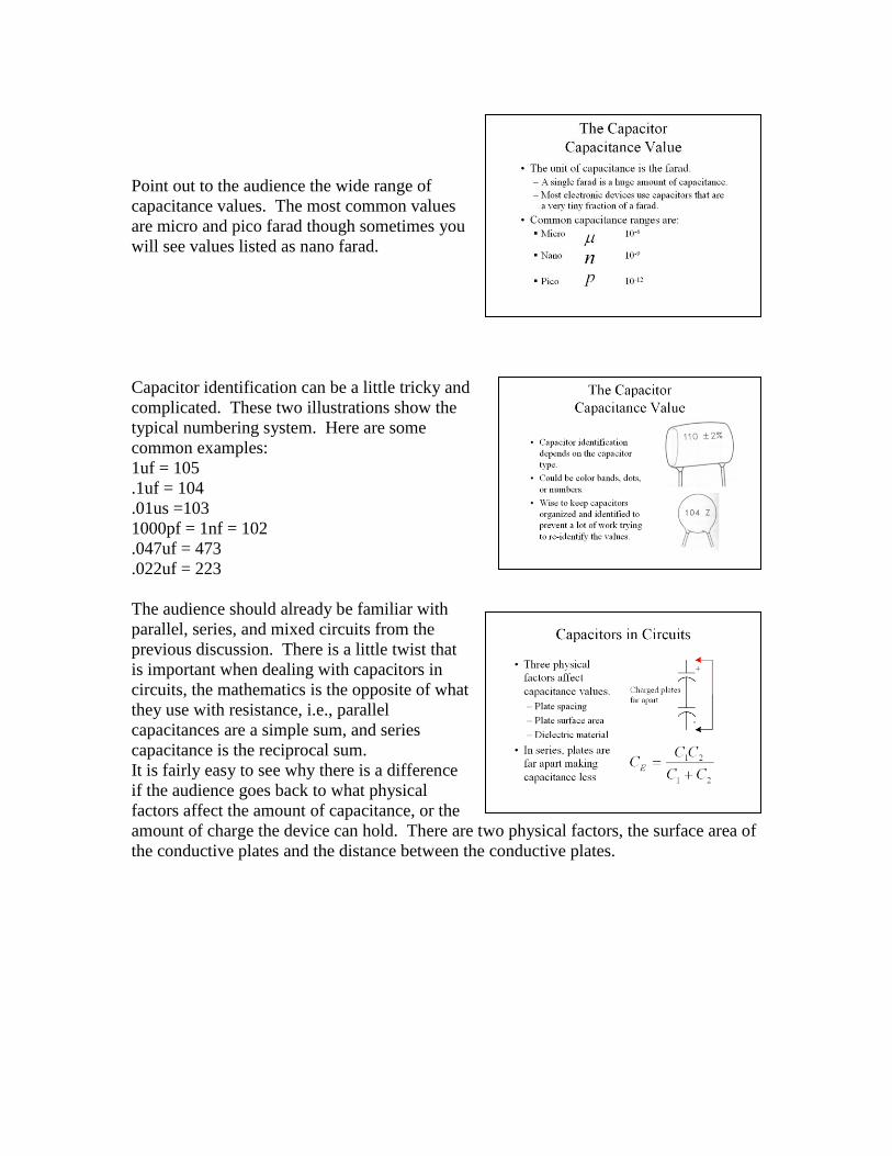
Point out to the audience the wide range of
capacitance values. The most common values
are micro and pico farad though sometimes you
will see values listed as nano farad.
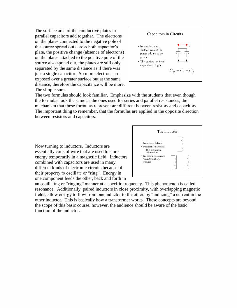
Capacitor identification can be a little tricky and
complicated. These two illustrations show the
typical numbering system. Here are some
common examples: 1uf = 105
.1uf = 104
.01us =103
1000pf = 1nf = 102
.047uf = 473
.022uf = 223
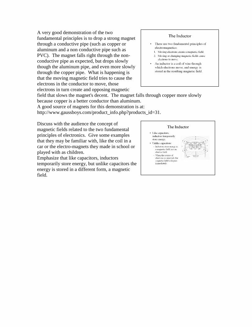
The audience should already be familiar with
parallel, series, and mixed circuits from the
previous discussion. There is a little twist that
is important when dealing with capacitors in
circuits, the mathematics is the opposite of what
they use with resistance, i.e., parallel
capacitances are a simple sum, and series
capacitance is the reciprocal sum. It is fairly easy to see why there is a difference
if the audience goes back to what physical
factors affect the amount of capacitance, or the
amount of charge the device can hold. There are two physical factors, the surface area of
the conductive plates and the distance between the conductive plates.
The surface area of the conductive plates in
parallel capacitors add together. The electrons
on the plates connected to the negative pole of
the source spread out across both capacitor’s
plate, the positive change (absence of electrons)
on the plates attached to the positive pole of the
source also spread out, the plates are still only
separated by the same distance as if there was
just a single capacitor. So more electrons are
exposed over a greater surface but at the same
distance, therefore the capacitance will be more.
The simple sum. The two formulas should look familiar. Emphasize with the students that even though
the formulas look the same as the ones used for series and parallel resistances, the
mechanism that these formulas represent are different between resistors and capacitors.
The important thing to remember, that the formulas are applied in the opposite direction
between resistors and capacitors.
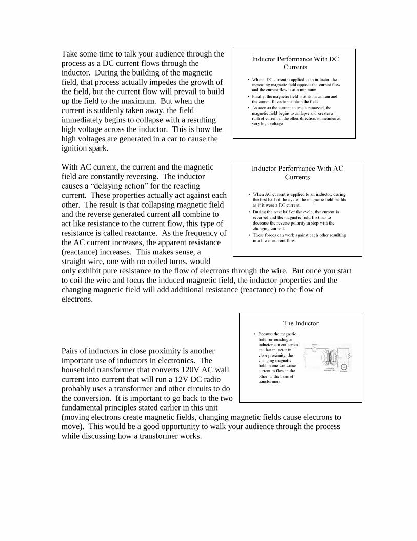
Now turning to inductors. Inductors are
essentially coils of wire that are used to store
energy temporarily in a magnetic field. Inductors
combined with capacitors are used in many
different kinds of electronic circuits because of
their property to oscillate or “ring”. Energy in
one component feeds the other, back and forth in
an oscillating or “ringing” manner at a specific frequency. This phenomenon is called
resonance. Additionally, paired inductors in close proximity, with overlapping magnetic
fields, allow energy to flow from one inductor to the other, by “inducing” a current in the
other inductor. This is basically how a transformer works. These concepts are beyond
the scope of this basic course, however, the audience should be aware of the basic
function of the inductor.
A very good demonstration of the two
fundamental principles is to drop a strong magnet
through a conductive pipe (such as copper or
aluminum and a non conductive pipe such as
PVC). The magnet falls right through the non-
conductive pipe as expected, but drops slowly
though the aluminum pipe, and even more slowly
through the copper pipe. What is happening is
that the moving magnetic field tries to cause the
electrons in the conductor to move, those
electrons in turn create and opposing magnetic
field that slows the magnet's decent. The magnet falls through copper more slowly
because copper is a better conductor than aluminum. A good source of magnets for this demonstration is at:
http://www.gaussboys.com/product_info.php?products_id=31.
Discuss with the audience the concept of
magnetic fields related to the two fundamental
principles of electronics. Give some examples
that they may be familiar with, like the coil in a
car or the electro-magnets they made in school or
played with as children. Emphasize that like capacitors, inductors
temporarily store energy, but unlike capacitors the
energy is stored in a different form, a magnetic
field.

Discuss with the audience the physical makeup of
the typical inductor … a coil of wire. The
permeable material (meaning it accepts and
concentrates magnetic fields) helps to generate a
larger magnetic field in the inductor without
adding wire. The permeable materials are
metallic mixtures that usually include iron. The
magnetic field created by an inductor surrounds
the inductor. The toroid, or doughnut form, helps
to keep the magnetic field contained within the
immediate vicinity of the inductor. This is sometimes desirable so that inductors near
each other will not interact.
As in capacitance and the Farad, a single Henry is
a huge amount of inductance and would require a
very large component. In electronics, the values
of inductance are generally in the milli and micro
ranges.
All of these factors contribute to the value of
inductance. All of these factors are mathematically
related and an inductor’s value can be predicted
pretty well if these dimensions are known. The
math and the formulas are beyond the scope of this
course, but they are by no means too difficult for
those in the audience who are interested.
Take some time to talk your audience through the
process as a DC current flows through the
inductor. During the building of the magnetic
field, that process actually impedes the growth of
the field, but the current flow will prevail to build
up the field to the maximum. But when the
current is suddenly taken away, the field
immediately begins to collapse with a resulting
high voltage across the inductor. This is how the
high voltages are generated in a car to cause the
ignition spark.
With AC current, the current and the magnetic
field are constantly reversing. The inductor
causes a “delaying action” for the reacting
current. These properties actually act against each
other. The result is that collapsing magnetic field
and the reverse generated current all combine to
act like resistance to the current flow, this type of
resistance is called reactance. As the frequency of
the AC current increases, the apparent resistance
(reactance) increases. This makes sense, a
straight wire, one with no coiled turns, would
only exhibit pure resistance to the flow of electrons through the wire. But once you start
to coil the wire and focus the induced magnetic field, the inductor properties and the
changing magnetic field will add additional resistance (reactance) to the flow of
electrons.
Pairs of inductors in close proximity is another
important use of inductors in electronics. The
household transformer that converts 120V AC wall
current into current that will run a 12V DC radio
probably uses a transformer and other circuits to do
the conversion. It is important to go back to the two
fundamental principles stated earlier in this unit
(moving electrons create magnetic fields, changing magnetic fields cause electrons to
move). This would be a good opportunity to walk your audience through the process
while discussing how a transformer works.

The diode is a devise that allows current to flow
in only one direction. There are specialized
diodes, the light emitting diode (LED) and the
Zener diode that will be discussed later.
However, the basic principal is the same, the
current will flow in one direction, if current flow
is attempted in the opposite direction, the flow
will be blocked. Diodes find use in many electronic circuits. The audience probably has heard that diodes convert AC to DC. This is an over
simplification of how a diode operates, you will be clearing this misconception up in the
following discussion.
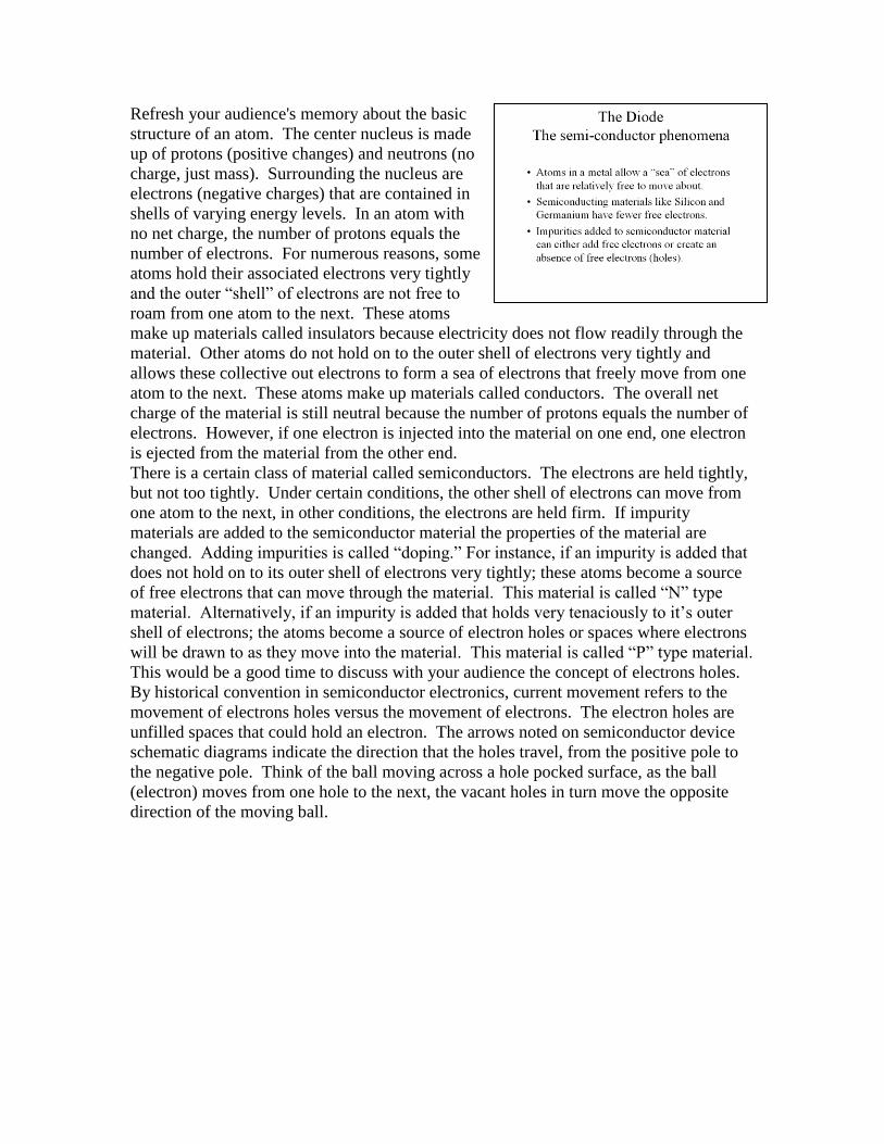
Refresh your audience's memory about the basic
structure of an atom. The center nucleus is made
up of protons (positive changes) and neutrons (no
charge, just mass). Surrounding the nucleus are
electrons (negative charges) that are contained in
shells of varying energy levels. In an atom with
no net charge, the number of protons equals the
number of electrons. For numerous reasons, some
atoms hold their associated electrons very tightly
and the outer “shell” of electrons are not free to
roam from one atom to the next. These atoms
make up materials called insulators because electricity does not flow readily through the
material. Other atoms do not hold on to the outer shell of electrons very tightly and
allows these collective out electrons to form a sea of electrons that freely move from one
atom to the next. These atoms make up materials called conductors. The overall net
charge of the material is still neutral because the number of protons equals the number of
electrons. However, if one electron is injected into the material on one end, one electron
is ejected from the material from the other end. There is a certain class of material called semiconductors. The electrons are held tightly,
but not too tightly. Under certain conditions, the other shell of electrons can move from
one atom to the next, in other conditions, the electrons are held firm. If impurity
materials are added to the semiconductor material the properties of the material are
changed. Adding impurities is called “doping.” For instance, if an impurity is added that
does not hold on to its outer shell of electrons very tightly; these atoms become a source
of free electrons that can move through the material. This material is called “N” type
material. Alternatively, if an impurity is added that holds very tenaciously to it’s outer
shell of electrons; the atoms become a source of electron holes or spaces where electrons
will be drawn to as they move into the material. This material is called “P” type material.
This would be a good time to discuss with your audience the concept of electrons holes.
By historical convention in semiconductor electronics, current movement refers to the
movement of electrons holes versus the movement of electrons. The electron holes are
unfilled spaces that could hold an electron. The arrows noted on semiconductor device
schematic diagrams indicate the direction that the holes travel, from the positive pole to
the negative pole. Think of the ball moving across a hole pocked surface, as the ball
(electron) moves from one hole to the next, the vacant holes in turn move the opposite
direction of the moving ball.
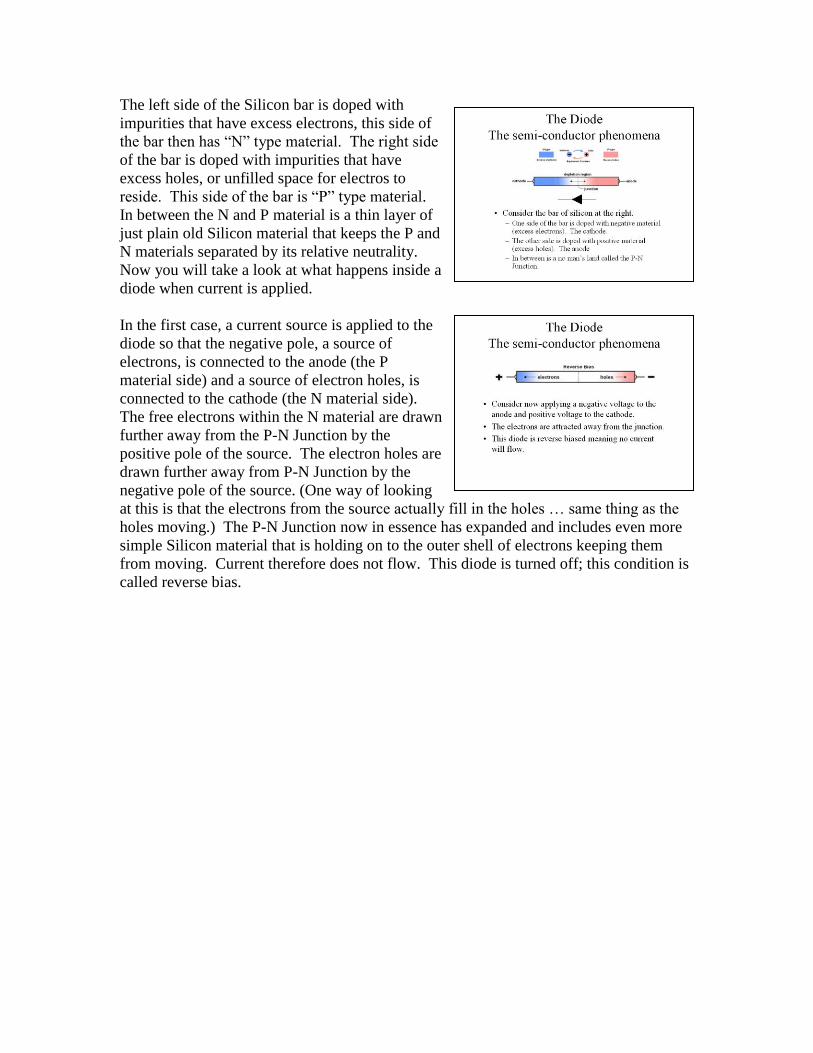
The left side of the Silicon bar is doped with
impurities that have excess electrons, this side of
the bar then has “N” type material. The right side
of the bar is doped with impurities that have
excess holes, or unfilled space for electros to
reside. This side of the bar is “P” type material.
In between the N and P material is a thin layer of
just plain old Silicon material that keeps the P and
N materials separated by its relative neutrality. Now you will take a look at what happens inside a
diode when current is applied.
In the first case, a current source is applied to the
diode so that the negative pole, a source of
electrons, is connected to the anode (the P
material side) and a source of electron holes, is
connected to the cathode (the N material side).
The free electrons within the N material are drawn
further away from the P-N Junction by the
positive pole of the source. The electron holes are
drawn further away from P-N Junction by the
negative pole of the source. (One way of looking
at this is that the electrons from the source actually fill in the holes … same thing as the
holes moving.) The P-N Junction now in essence has expanded and includes even more
simple Silicon material that is holding on to the outer shell of electrons keeping them
from moving. Current therefore does not flow. This diode is turned off; this condition is
called reverse bias.

Now in this second case, the poles of the source
are reversed. The electrons from the negative
pole of the source add to the excess electrons in
the N material. The electrons from the P
material are drawn to the positive pole of the
source to create more holes in the P material.
The result is that the N-P Junction is no longer a
no-mans land and the excess electrons and the
holes come together allowing the current to
flow. This situation is called forward biasing of
the diode.
The following two activities reinforce what has
just been presented. Work with the audience to
ensure they can identify the banded (Cathode)
end of the diode. This would be a good place to
talk about the purpose of the current limiting
resistor. When the diode is reversed biased,
current will not flow through the diode and the
protective resistor would not be needed.
However, when the diode is forward biased, the
diode conducts and is essentially a closed
switch or closed circuit with very little internal resistance and the full current available
would flow through the circuit potentially damaging the components within the circuit. Ask the audience to identify if the diode is reverse or forward biased. In turn ask them to
predict what type of meter indication they would expect. If the current were to flow in
this circuit, what would be the expected current? This type of calculation should be done
ahead of time, before making the measurement, so that the proper meter range will be
used.
This circuit is reverse biased and no current flows.

Using a 9-volt battery and a 330-ohm resistor,
assuming no resistance within the diode, using
Ohm’s law the current will be 27 milliamps. The
200m range would be appropriate in the next
activity. In this case, the diode is forward biased
and current will flow through the circuit. The
predicted current flow is 27 milliamps, but the
actual current flow through the circuit is 24
milliamps. You can use this difference to discuss with the
audience what is going on. They should come to
the conclusion that there is less than predicted current flow because there is additional
resistance somewhere in the circuit. You can lead them to the conclusion that perhaps
there is resistance in the diode. How could that go about determining if the diode is the
source of resistance?
One strategy is to use the circuit in the next activity.
In this circuit, the VOM is connected to read the
voltage across the diode. On the test bed, the
voltage drop was .709 volts. Using the current
measured in the previous activity, 24 milliamps,
and this voltage drop of .709 volts in Ohm’s law
results in a resistance within the diode of 29
ohms. Taking this a step further, the total
resistance of the circuit is 330 + 29 = 359 ohms.
Using Ohm’s law, the current through this circuit
with a 9-volt battery should be 25 milliamps … a
little closer to the value observed. Here is where you can discuss with the audience that although the diode is forward biased
and is conducting electrons (or holes depending on your point of view), there is some
inherent internal resistance in the diode. The typical voltage drop they will experience
with a conducting diode is approximately .7 volts.
The current carrying capacity of a diode must be considered in circuit design. While
there is a .7-volt drop across the diode due to the internal resistance, this resistance will in
turn create heat when current is flowing through the diode, and this heat must go
someplace. Therefore diodes a rated by their ability to handle current as well as their
ability to hold back voltage (maximum reversed bias voltage before failure). It is up to
the designer to consider the current capabilities and limit the current by proper current
limiting resistor choice.
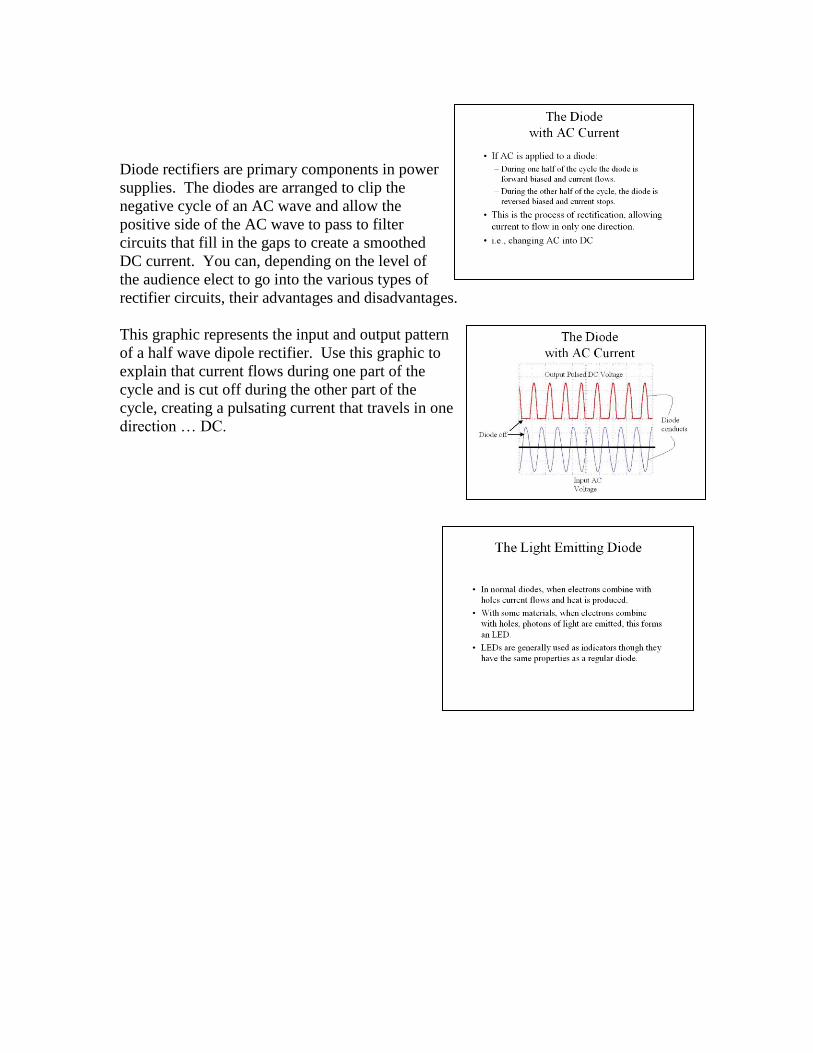
Diode rectifiers are primary components in power
supplies. The diodes are arranged to clip the
negative cycle of an AC wave and allow the
positive side of the AC wave to pass to filter
circuits that fill in the gaps to create a smoothed
DC current. You can, depending on the level of
the audience elect to go into the various types of
rectifier circuits, their advantages and disadvantages.
This graphic represents the input and output pattern
of a half wave dipole rectifier. Use this graphic to
explain that current flows during one part of the
cycle and is cut off during the other part of the
cycle, creating a pulsating current that travels in one
direction … DC.
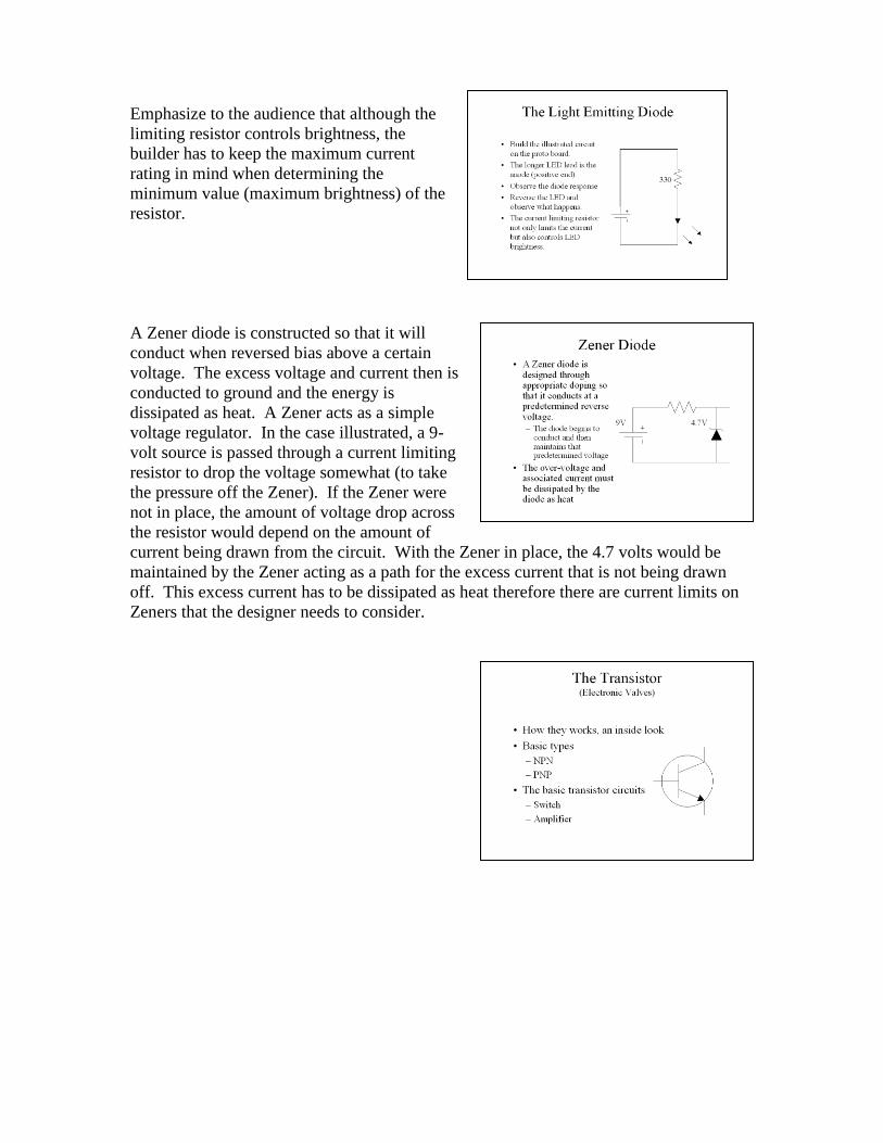
Emphasize to the audience that although the
limiting resistor controls brightness, the
builder has to keep the maximum current
rating in mind when determining the
minimum value (maximum brightness) of the
resistor.
A Zener diode is constructed so that it will
conduct when reversed bias above a certain
voltage. The excess voltage and current then is
conducted to ground and the energy is
dissipated as heat. A Zener acts as a simple
voltage regulator. In the case illustrated, a 9-
volt source is passed through a current limiting
resistor to drop the voltage somewhat (to take
the pressure off the Zener). If the Zener were
not in place, the amount of voltage drop across
the resistor would depend on the amount of
current being drawn from the circuit. With the Zener in place, the 4.7 volts would be
maintained by the Zener acting as a path for the excess current that is not being drawn
off. This excess current has to be dissipated as heat therefore there are current limits on
Zeners that the designer needs to consider.
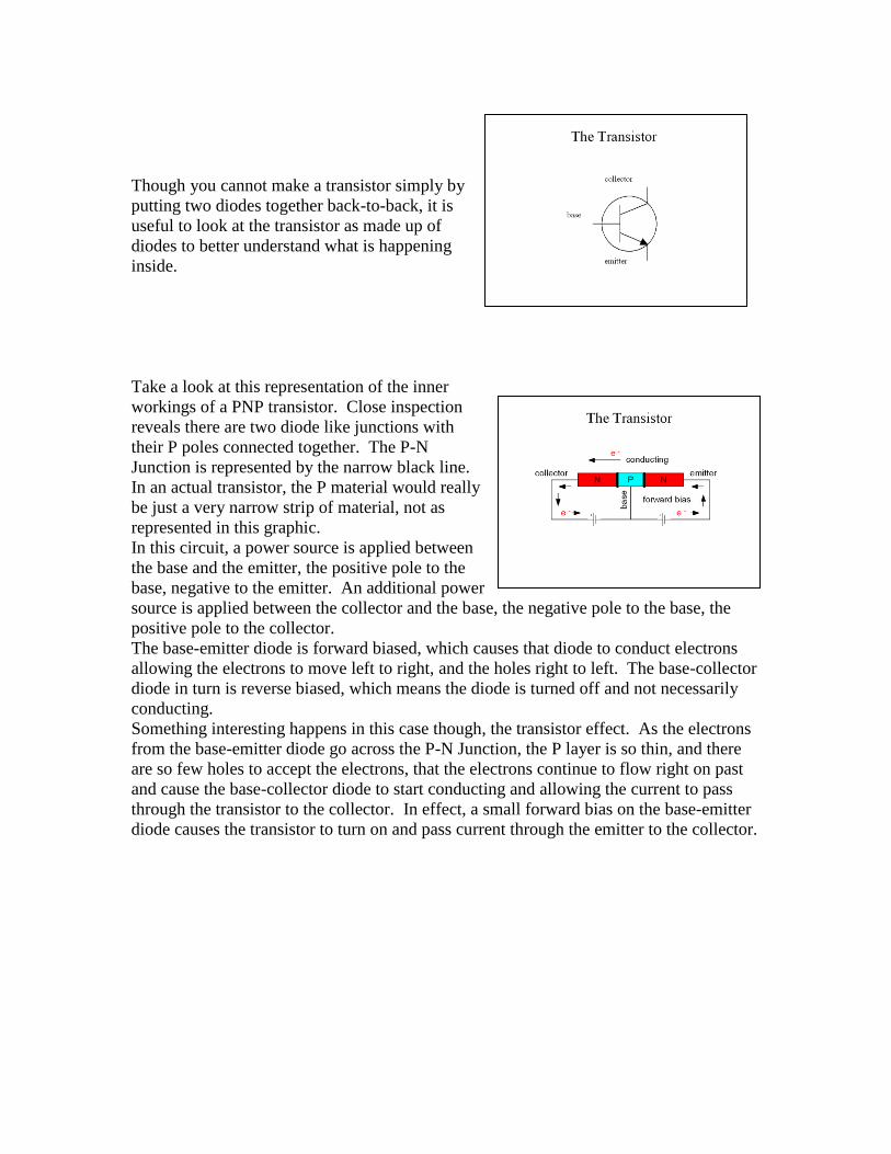
Though you cannot make a transistor simply by
putting two diodes together back-to-back, it is
useful to look at the transistor as made up of
diodes to better understand what is happening
inside.
Take a look at this representation of the inner
workings of a PNP transistor. Close inspection
reveals there are two diode like junctions with
their P poles connected together. The P-N
Junction is represented by the narrow black line.
In an actual transistor, the P material would really
be just a very narrow strip of material, not as
represented in this graphic. In this circuit, a power source is applied between
the base and the emitter, the positive pole to the
base, negative to the emitter. An additional power
source is applied between the collector and the base, the negative pole to the base, the
positive pole to the collector.
The base-emitter diode is forward biased, which causes that diode to conduct electrons
allowing the electrons to move left to right, and the holes right to left. The base-collector
diode in turn is reverse biased, which means the diode is turned off and not necessarily
conducting.
Something interesting happens in this case though, the transistor effect. As the electrons
from the base-emitter diode go across the P-N Junction, the P layer is so thin, and there
are so few holes to accept the electrons, that the electrons continue to flow right on past
and cause the base-collector diode to start conducting and allowing the current to pass
through the transistor to the collector. In effect, a small forward bias on the base-emitter
diode causes the transistor to turn on and pass current through the emitter to the collector.
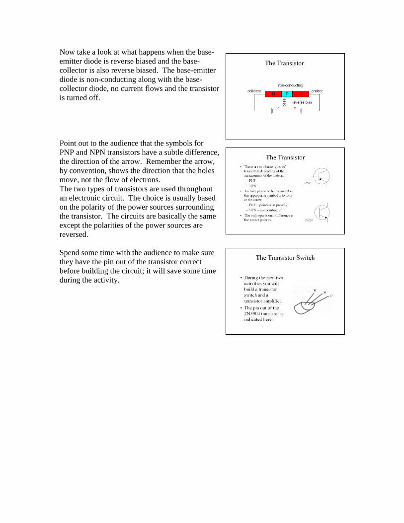
Now take a look at what happens when the base-
emitter diode is reverse biased and the base-
collector is also reverse biased. The base-emitter
diode is non-conducting along with the base-
collector diode, no current flows and the transistor
is turned off.
Point out to the audience that the symbols for
PNP and NPN transistors have a subtle difference,
the direction of the arrow. Remember the arrow,
by convention, shows the direction that the holes
move, not the flow of electrons. The two types of transistors are used throughout
an electronic circuit. The choice is usually based
on the polarity of the power sources surrounding
the transistor. The circuits are basically the same
except the polarities of the power sources are
reversed.
Spend some time with the audience to make sure
they have the pin out of the transistor correct
before building the circuit; it will save some time
during the activity.

The audience will need some help in first
determining the transistor pin outs and then
installing the LED. Reminded them that the
positive side (anode) of the LED is the longer
lead. In this circuit, the 330-ohm resistor in the
collector circuit limits the current through the
LED. Remember when the transistor begins to
conduct; the path through the transistor is very
low resistance. Without the current limiting
resistor, too much current could flow and
damage the components.
Additionally, the 1000-ohm resistor in the base circuit also limits current. In this case,
when the base-emitter diode conducts, there is a low resistance path. Without current
limiting, the transistor could be damaged.
When this circuit is completed, nothing should happen because the base-emitter diode of
the transistor is not forward biased so the transistor does not conduct.
When the base is connected to 9 volts, the base-
emitter diode is forward biased and conducts. This
in turn turns on the transistor and the current flows
through the LED to turn it on. The audience should
note that LED goes off when the base voltage is
removed.
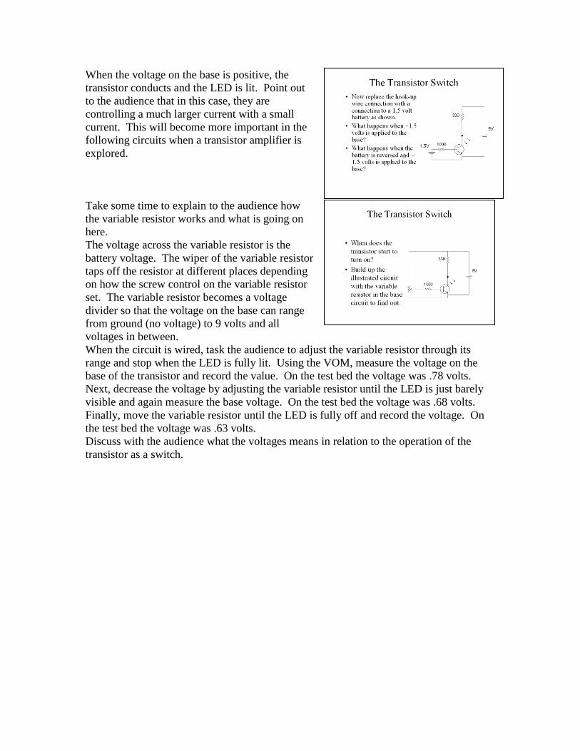
When the voltage on the base is positive, the
transistor conducts and the LED is lit. Point out
to the audience that in this case, they are
controlling a much larger current with a small
current. This will become more important in the
following circuits when a transistor amplifier is
explored.
Take some time to explain to the audience how
the variable resistor works and what is going on
here. The voltage across the variable resistor is the
battery voltage. The wiper of the variable resistor
taps off the resistor at different places depending
on how the screw control on the variable resistor
set. The variable resistor becomes a voltage
divider so that the voltage on the base can range
from ground (no voltage) to 9 volts and all
voltages in between.
When the circuit is wired, task the audience to adjust the variable resistor through its
range and stop when the LED is fully lit. Using the VOM, measure the voltage on the
base of the transistor and record the value. On the test bed the voltage was .78 volts.
Next, decrease the voltage by adjusting the variable resistor until the LED is just barely
visible and again measure the base voltage. On the test bed the voltage was .68 volts.
Finally, move the variable resistor until the LED is fully off and record the voltage. On
the test bed the voltage was .63 volts.
Discuss with the audience what the voltages means in relation to the operation of the
transistor as a switch.
Task the audience to research available ham
radio literature and find a simple circuit that
they would like to build. Their final exam will
be the construction of this circuit and a
classroom demonstration of it. During the
demonstration, they will be asked to describe
how the project demonstrates the concepts
developed in the course.


![Multisim 14.1 Power Pro ComponentsMultisim 14.1 Power Pro Components Page 1 of 785 0 Ohm [CAT10-000J4LF] 0 Ohm [CAT16-000J2GLF] 0 Ohm [CAT16-000J2LF] 0 Ohm [CAT16-000J4GLF]](https://img.dokumen.tips/doc/110x75/5f50c78d85d2ce148a6061d9/multisim-141-power-pro-components-multisim-141-power-pro-components-page-1-of.jpg)