Embed Size (px)
Citation preview

FALL 2009 WWW.WWDMAG.COM
A supplement to Water & Wastes Digest
prepared in cooperation with the
MembraneInnovationTrends and applications in the rapidly growing membrane industry
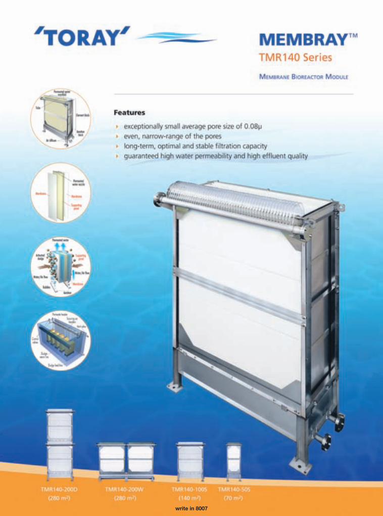
write in 8007
MEMBRANE TECHNOLOGY I 3
•editorial
It’s good to be in the membrane industry, even in this economy.
The industry is growing at a rapid pace. A study published in April by The Freedonia Group, Inc., based out of Cleveland, predicted that global demand for membranes will exceed $15 billion in 2012, an increase of 8.6%.
Reasons for this prediction are wide and varied. There is increased attention being given to disposal of industrial waste and food and beverage regulations. Apparent in the southwestern U.S. and in many parts of the world is a gap-ing lack of quality potable water, and as a result, residents of these areas must rely on poor-quality surface water and brackish water. Membranes can be a big part of the solu-tions to these problems.
Necessity is the mother of invention, as the saying goes. As the membrane industry grows globally, it must keep up with all the world’s needs. There are various types of water that people in Asia, Africa and the Middle East have to rely on for potable water and thus, membrane technology must adapt. True to form, the membrane industry has responded with cleaner, more efficient polymeric membranes and most recently, ceramic membranes. Still in the early stages of pilot studies and general acceptance in the U.S., these membranes have great abilities to treat a wide range of water qualities—including surface water and reclaimed water—and have the potential to last 15 to 20 years. (See page 18 for more on Membrane Technology’s coverage of ceramic membranes.)
The need for quality water keeps growing, for certain, and the membrane industry keeps growing and producing innovative solutions. It would seem these two factors could only equal a good thing. I’m convinced that if the mem-brane industry keeps being innovative and keeps the tech-nology as low-cost and energy-efficient as possible, great things can happen.
In 2010, Membrane Technology will be published three times, and will continue to offer technical articles and case studies that offer insight to the rapidly expanding membrane market. We would like to welcome readers’ feedback; please e-mail me at [email protected] and tell me what other membrane content you would like to see within these pages.
Clare Pierson, managing [email protected]
Positive Growth Ahead04 ROs Retain & Produce PowerPower-generating station’s RO elements deliver effective performance after 17 years in service
07 Two Years LaterLessons learned in launching the Kay Bailey Hutchinson desalination plant
09 Simulation for MBR OptimizationMatching energy input to pollutant loads
11 Chemical-Free CleaningMechanical cleaning process removes membrane deposits, enhances flux
14 Downstream DefendersMBRs prove to be a must in meeting stringent surface water discharge limits in Texas
16 Upgrading, Reclaiming & SavingAdvanced wastewater treatment facility helps a California city exceed specifications
18 Ceramic’s Critical PointResearch, applications and potential growth of ceramic membranes
c o n t e n t s 2009
SCRANTON GILLETTE COMMUNICATIONS3030 W. Salt Creek Ln., Ste. 201, Arlington Heights, IL 60005-5025
tel: 847.298.6622 • fax: 847.390.0408 • www.wwdmag.com
EDITORIAL STAFF Editorial Director Neda Simeonova Managing Editor Clare Pierson Associate Editor Caitlin Cunningham Associate Editor Rebecca Wilhelm Graphic Designer Maria Choronzuk Web Editor Adam Terese
A DV E RT ISI NG & S A L E S6900 E. Camelback, Suite 400 • Scottsdale, AZ 85251
tel: 480.941.0510 • fax: 480.423.1443 Regional Sales Manager David Rairigh
[email protected] (phone x25) Regional Sales Manager Eric Smith [email protected] (phone x14) Regional Sales Manager Fred Ferris [email protected] (Arlington Heights office, 847.391.1003) Regional Sales Manager Brenda Yanez
[email protected] (phone x12) Regional Sales Manager Lori Glenn [email protected] (phone x17) New Business Media Rep Tami Morrell [email protected] (Arlington Heights office, 847.391.1002) Internet Sales Rep. Michael Mansour [email protected] (phone x16) Classified Sales Manager Donna Aly [email protected] (phone x13) Reprint Coordinator Adrienne Miller [email protected] (Arlington Heights office, 847.391.1036)
MANAGEMENT Vice President/Publisher Dennis Martyka [email protected] Associate Publisher Greg Tres [email protected] VP Events Harry Urban [email protected] VP Custom Publishing & Diane Vojcanin Creative Services [email protected] Director of Creative Sandi Stevenson Services [email protected] Circulation Director Mike Serino [email protected]
COR POR AT E Chairperson K.S. Gillette President/CEO E.S. Gillette Sr. Vice President A. O’Neill Chairman Emeritus H.S. Gillette (1922-2003)
MEMBRANE TECHNOLOGY

A GLV COMPANY© Copyright 2009 GLV. All rights reserved.–0209
When it comes to MBRs… simplicity saves money
No backpulsesystemrequired
No on-sitechemicalstoragefacilities
No recoverycleaningrequired
Simplifiedheadworksrequirements
No basindraining ortank liningrequired
Singlerecyclestream
1 2 3 4 5 6
Simple in design and easy to operate, an Enviroquip® MBR system provides the benefits of membrane
technology without the complexity. From point-of-use decentralized systems to custom municipal
installations, Enviroquip has designed and/or commissioned over 100 MBR facilities.
Delivering solutions today…for tomorrow’s water™
E-mail: [email protected]
Write in xxxwrite in 8002

4 I MEMBRANE TECHNOLOGY FALL 2009
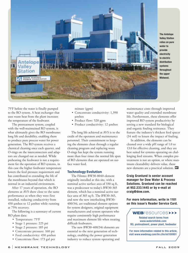
In 1992, a reverse osmosis (RO) system utilizing 168 DOW Filmtec BW30-8040 elements was installed
to pretreat the feedwater to the ion-exchange system for the Antelope Valley Station (AVS) just outside of Beulah, N.D. The RO ion-exchange system and other pretreatment equipment were installed to provide boiler feedwater to the generating station.
After 17 years, the original RO ele-ments are still in service, well exceeding the industry-expected life span. The dura-bility and cleanability of RO elements, combined with proper pretreatment and good plant maintenance, makes such an achievement possible.
The FacilityPower-generation facilities rely on pure
water to make steam, turn turbines and generate electricity. Located seven miles
northwest of the town of Beulah, the Antelope Valley Station (AVS)—a lignite-based electric generating station with a capacity of 900,000 kW—relies on pure water to provide electricity to member electric distribution systems throughout the upper Midwest.
The station is operated by Basin Electric Power Cooperative and was established in 1984, making it the newest coal-based power plant in the state. An integral part of Basin Electric’s generating and transmission network, most energy produced at AVS is sent to a substation near Huron, S.D., where it is then deliv-ered to Basin Electric’s member systems.
The feedwater source for AVS is Lake Sakakawea, which is a reservoir of Missouri River water. Filmtec elements were selected to be installed in the AVS because of their high productivity, long membrane life and durability. After 17
years, these elements are still efficiently producing clean process water from this surface water source.
Treatment ProcessThe system is made up of four trains
of a 5-2 array of vessels, each contain-ing six elements. The feedwater arrives from the lake via a 9-mile pipeline, where it goes through a prechlorination step before the clarifiers. From the clarifiers, it is cold-lime-softened, and liquid ferric sulfate and a polymer are added as coagu-lation aids.
The water is then pumped to a clear well that holds 1 million gal and onto the main plant, where it goes through a sand/anthracite filter and then a separate carbon filtration step. Additional pretreat-ment steps include 5-μm cartridge filters, addition of sulfuric acid to reduce the pH to 7.0 and a temperature increase to about
Power-generating station’s RO elements deliver effective performance after 17 years in service
ROs Retain & Produce Power
By Craig Granlund
•case study
6 I MEMBRANE TECHNOLOGY FALL 2009
75°F before the water is finally pumped to the RO system. A heat exchanger that uses waste heat from the plant increases the temperature of the feedwater.
The pretreatment system, coupled with the well-maintained RO system, is what ultimately gives the RO membranes long life and durability, enabling them to produce pure process water for power generation. The RO system receives a chemical cleaning once each quarter, and O-rings on the interconnectors and adap-tors are changed out as needed. While preheating the feedwater is not a require-ment for the operation of RO systems, in this case the higher feedwater temperature lowers the feed pressure requirement and has contributed to extending the life of the membranes beyond that which is normal in an industrial environment.
After 17 years of operation, the RO elements at AVS show close to the same performance as when they were first installed, reducing conductivity from 450 μmhos to 12 μmhos while running at 75% recovery.
The following is a summary of current RO plant data:
Temperature: 75°F• Stage 1 pressure: 225 psi• Stage 2 pressure: 185 psi• Concentrate pressure: 160 psi• Feed conductivity: 450 μmhos• Concentrate f low: 173 gal per •
minute (gpm)Concentrate conductivity: 1,390 • μmhosProduct f low: 520 gpm• Product conductivity: 12 μmhos•
The long life achieved at AVS is to the credit of the operators and maintenance personnel. Their commitment to keep-ing the elements clean through a regular cleaning program and replacing worn O-rings has kept the system running more than four times the normal life span of RO elements that are operated on sur-face water feed.
Technology EvolutionThe Filmtec BW30-8040 element
originally installed at this site, with a nominal active surface area of 330 sq ft, was a predecessor to today’s BW30-365 element, which has a nominal active sur-face area of 365 sq ft. The BW30-365, and now the new interlocking BW30-400/34i, are traditional element options for system designers, original equipment manufacturers and system operators who require consistently high performance and maximum element life when treating difficult feedwaters.
The new BW30-400/34i elements are essential to the next generation of tech-nology, enabling the power generation industry to reduce system operating and
maintenance costs through improved water quality and extended membrane life. Furthermore, these elements offer improved RO system productivity by setting a new standard for biological and organic fouling resistance. They feature the industry’s thickest feed spacer (34 mil) to lessen the impact of fouling.
In addition, the elements can be cleaned over a wide pH range of 1.0 to 13.0 for effective cleaning, and they are best suited for systems operating on chal-lenging feed streams. When complex pre-treatment is not an option, or where max-imum cleanability delivers value, these new elements are a practical solution. MT
Craig Granlund is senior account
manager for Dow Water & Process
Solutions. Granlund can be reached
at 952.233.1445 or by e-mail at
For more information, write in 1101
on this issue’s Reader Service Card.
WEBresourcesRelated search terms from
www.waterinfolink.com:
RO, pretreatment, power plant, feedwater
For more information related to this article,
visit www.wwdmag.com/lm.cfm/mt100901
The Antelope
Valley Station
relies on pure
water to
provide
electricity
to electric
distribution
systems
throughout
the upper
Midwest.
Seated at the western tip of Texas and located at the northern extreme of the Chihuahuan desert, El Paso
is a large Southwestern city of nearly 700,000 residents. This mountainous city is part of a larger metropolitan area that includes Ft. Bliss, Texas; Ciudad Juarez, Mexico; and several smaller communi-ties. With its arid climate, the city thirsts for water resources, which are extremely important for the viability and sustain-ability of the community.
For much of its history, El Paso was highly dependent on groundwater from one aquifer. Since the early 1900s, the community relied on the Hueco Bolson to provide most of the water supply for the area. Because El Paso needed more water, another well was drilled and not much thought was given to the potential of depleting the aquifer. After pump-ing levels dropped and salinity increased gradually, a series of groundwater models were developed in the 1970s; the results were frightening.
The models showed a high likelihood of increasing brackish water intrusion into freshwater wells. Exhaustion of the aquifer would cause saline and brackish encroach-ment to become more significant—to the point that the remaining freshwater supplies would be so heavily impacted by migration of salt that without desalina-tion, the water would be unusable. Despite serious flaws that would not be discovered until early in the new century, the results were noted and the importance of desali-nation was given consideration.
Planning PhaseTo begin, a comprehensive Water
Resources Management Plan was devel-oped that examined and prioritized all of
the available information. A roadmap also was developed that included, in order, increased conservation, reclaimed water, surface water, local groundwater, desali-nation and importation of groundwater. With the completion of the plan in the 1990s, it was put in motion. Enormous strides were taken in water conservation, and there were increases in reclaimed water and surface water and better utiliza-tion of local groundwater.
By 1993, the first pilot plant that treat-ed brackish water from the Rio Grande using reverse osmosis (RO) membranes was constructed. In parallel, efforts were made to measure the amount of brackish water available for treatment and to ana-lyze the possibilities for concentrate dis-posal. Ten years later, sufficient informa-tion was available to initiate a new round
of pilot testing on the Hueco Bolson brackish groundwater. This new series of tests would include extensive piloting and research on concentrate disposal.
Although it is possible to take exist-ing water quality and—through the use of various models—select membranes suitable for meeting some treatment goal, there is no substitute for pilot plant testing. A pilot plant is key, not only for membrane selection but also for selection of the proper pretreatment system.
During the time of testing, Ft. Bliss had also identified the need to utilize brackish groundwater and area form-ations with a potential for deep well injection of concentrate. At the urging of Rep. Silvestre Reyes and Sen. Kay Bailey Hutchison, an agreement was reached between Ft. Bliss and El Paso Water
Lessons learned in launching the Kay Bailey Hutchinson desalination plant
Two Years Later
By John Balliew
•case study
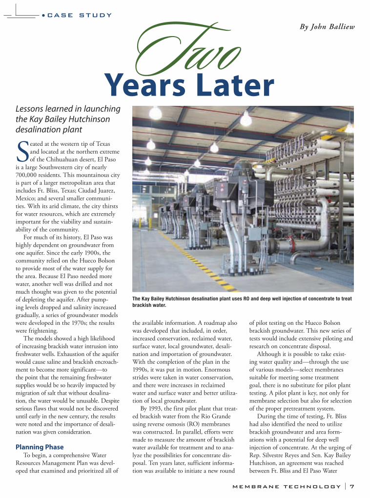
The Kay Bailey Hutchinson desalination plant uses RO and deep well injection of concentrate to treat
brackish water.
MEMBRANE TECHNOLOGY I 7
8 I MEMBRANE TECHNOLOGY FALL 2009
Utilities (EPWU) to go forward with a joint desalination plant that would use RO and deep well injection of concentrate.
New PlantBased on a careful analysis of the
movement of brackish groundwater by EPWU Water Resources Manager Dr. Bill Hutchison, a decision was made to locate the plant close to existing wells that had become brackish soon after they were drilled in the mid-1980s. A string of new wells would be constructed, creating a subterranean trough to intercept the brackish water movement and direct it to the new plant.
After the location of the plant had been decided on, the next approach was education. EPWU strongly believes in the power of education, as it is critical to achieving water conservation goals and implementing the entire water resource strategy. A key part of educating custom-ers is to provide access to facilities so that they can see what they are investing in and where their water is coming from.
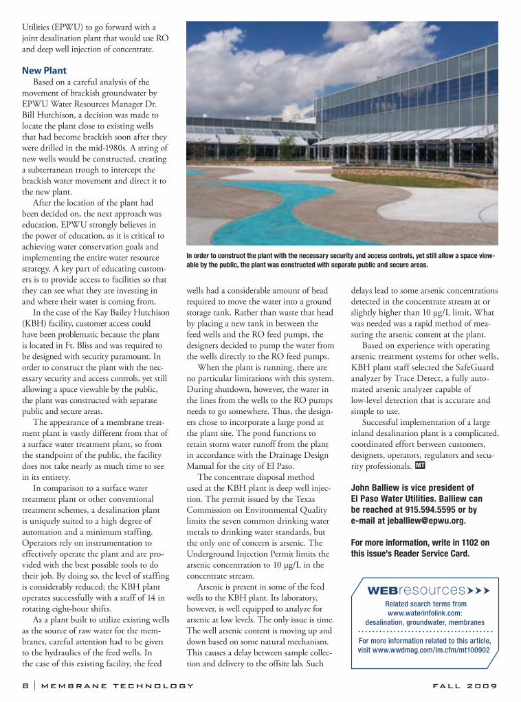
In the case of the Kay Bailey Hutchison (KBH) facility, customer access could have been problematic because the plant is located in Ft. Bliss and was required to be designed with security paramount. In order to construct the plant with the nec-essary security and access controls, yet still allowing a space viewable by the public, the plant was constructed with separate public and secure areas.
The appearance of a membrane treat-ment plant is vastly different from that of a surface water treatment plant, so from the standpoint of the public, the facility does not take nearly as much time to see in its entirety.
In comparison to a surface water treatment plant or other conventional treatment schemes, a desalination plant is uniquely suited to a high degree of automation and a minimum staffing. Operators rely on instrumentation to effectively operate the plant and are pro-vided with the best possible tools to do their job. By doing so, the level of staffing is considerably reduced; the KBH plant operates successfully with a staff of 14 in rotating eight-hour shifts.
As a plant built to utilize existing wells as the source of raw water for the mem-branes, careful attention had to be given to the hydraulics of the feed wells. In the case of this existing facility, the feed
wells had a considerable amount of head required to move the water into a ground storage tank. Rather than waste that head by placing a new tank in between the feed wells and the RO feed pumps, the designers decided to pump the water from the wells directly to the RO feed pumps.
When the plant is running, there are no particular limitations with this system. During shutdown, however, the water in the lines from the wells to the RO pumps needs to go somewhere. Thus, the design-ers chose to incorporate a large pond at the plant site. The pond functions to retain storm water runoff from the plant in accordance with the Drainage Design Manual for the city of El Paso.
The concentrate disposal method used at the KBH plant is deep well injec-tion. The permit issued by the Texas Commission on Environmental Quality limits the seven common drinking water metals to drinking water standards, but the only one of concern is arsenic. The Underground Injection Permit limits the arsenic concentration to 10 μg/L in the concentrate stream.
Arsenic is present in some of the feed wells to the KBH plant. Its laboratory, however, is well equipped to analyze for arsenic at low levels. The only issue is time. The well arsenic content is moving up and down based on some natural mechanism. This causes a delay between sample collec-tion and delivery to the offsite lab. Such
delays lead to some arsenic concentrations detected in the concentrate stream at or slightly higher than 10 μg/L limit. What was needed was a rapid method of mea-suring the arsenic content at the plant.
Based on experience with operating arsenic treatment systems for other wells, KBH plant staff selected the SafeGuard analyzer by Trace Detect, a fully auto-mated arsenic analyzer capable of low-level detection that is accurate and simple to use.
Successful implementation of a large inland desalination plant is a complicated, coordinated effort between customers, designers, operators, regulators and secu-rity professionals. MT
John Balliew is vice president of
El Paso Water Utilities. Balliew can
be reached at 915.594.5595 or by
e-mail at [email protected].
For more information, write in 1102 on
this issue’s Reader Service Card.
WEBresourcesRelated search terms from
www.waterinfolink.com:
desalination, groundwater, membranes
For more information related to this article,
visit www.wwdmag.com/lm.cfm/mt100902
In order to construct the plant with the necessary security and access controls, yet still allow a space view-
able by the public, the plant was constructed with separate public and secure areas.

Designing a membrane bioreactor (MBR) facility for optimum performance is challenging.
Diurnal flow profiles, basin volumes and equipment capacities are unique to each project. Programmed delay times and process lag times make it impossible to analyze the following critical process interactions with a simple spreadsheet analysis—controlling basin instantaneous volume; the facility’s diurnal influent flow profile; and MBR capacity staging as a function of controlling basin level.
Accurately evaluating those relation-ships at the design stage is essential. Enviroquip’s EQLogix simulator is a software tool that dynamically simulates facility processes and provides data to support utilization and energy estimates at the design stage. The simulator also provides control settings that may be used at the startup of a new MBR facil-ity or to optimize performance of an existing facility.
MBR ProcessA typical MBR facility is shown in
Figure 1. Screened inf luent is fed into the equalization basin. From there, it is pumped to the anoxic basin, where it is mixed with recycled activated sludge. The slightly oxic sludge is quickly depleted of oxygen, allowing denitrification to occur. The denitri-fied blended sludge is pumped forward into the pre-aeration basin where
additional biological treatment occurs. The MBR system is configured such
that membrane capacity is incrementally taken in and out of service based on actual demand. Capacity staging enables the plant to run more energy efficiently by operating fewer membrane basins at higher flux rates. In simple terms, the programmable logic controller running the plant evaluates the controlling basin level and automatically selects the flux and number of membrane basins neces-sary to process influent flow efficiently. This approach is also referred to as energy matching.
Even though some membrane basins are idle at periods of low flow, mixed liquor is still recycled through them and air is periodically pulsed into the basins in order to keep the biology aerobic and the membrane units ready for service. This is referred to as the intermittent mode.
Maintaining the MBR basins in a combination of intermittent mode and filter mode reduces energy consump-tion by avoiding inefficient operation. Inefficient operation is characterized by low flux operation (higher kW per gal-lon processed) or excessive on-off cycling (equipment wear and tear). Return acti-vated sludge stays on at all times to pro-mote consistent mixed liquor suspended solids concentrations between membrane basins in different modes of operation (intermittent or filter mode).
Because a typical facility must accommodate a wide range of waste and hydraulic loads, automatic controls are provided to maintain idle membrane basins in a condition that will allow
them to be staged on and off as required
by influent flow. Lead and lag mem-brane basins are automatically rotated to equalize utilization.
Accurate PredictionEQLogix is a modular, standards-
based program that ensures predictable operation of every Enviroquip MBR facility. EQLogix incrementally stages membrane basins in response to diurnal flow variations, thereby allowing the MBR system to efficiently and appropri-ately process incoming flows.
Appropriate capacity staging matches the amount of energy put into the system to the amount of wastewater being treated, minimizing energy costs and maximizing the intervals between membrane maintenance cleanings. The capacity-staging algorithm monitors level in the controlling basin, and as level increases or decreases in response to influent flow, MBR basins are automati-cally placed into and out of service.
The simulator is a modified ver-sion of the EQLogix control system programming. It dynamically simulates
MEMBRANE TECHNOLOGY I 9
Matching energy input to pollutant loads
Simulation for MBR
Optimization
By John Alligood & Gabriel Cantu
•technical article
Figure 1. A typical MBR facility—equalization
basin, anoxic basin, pre-aeration basin and
biological treatment.
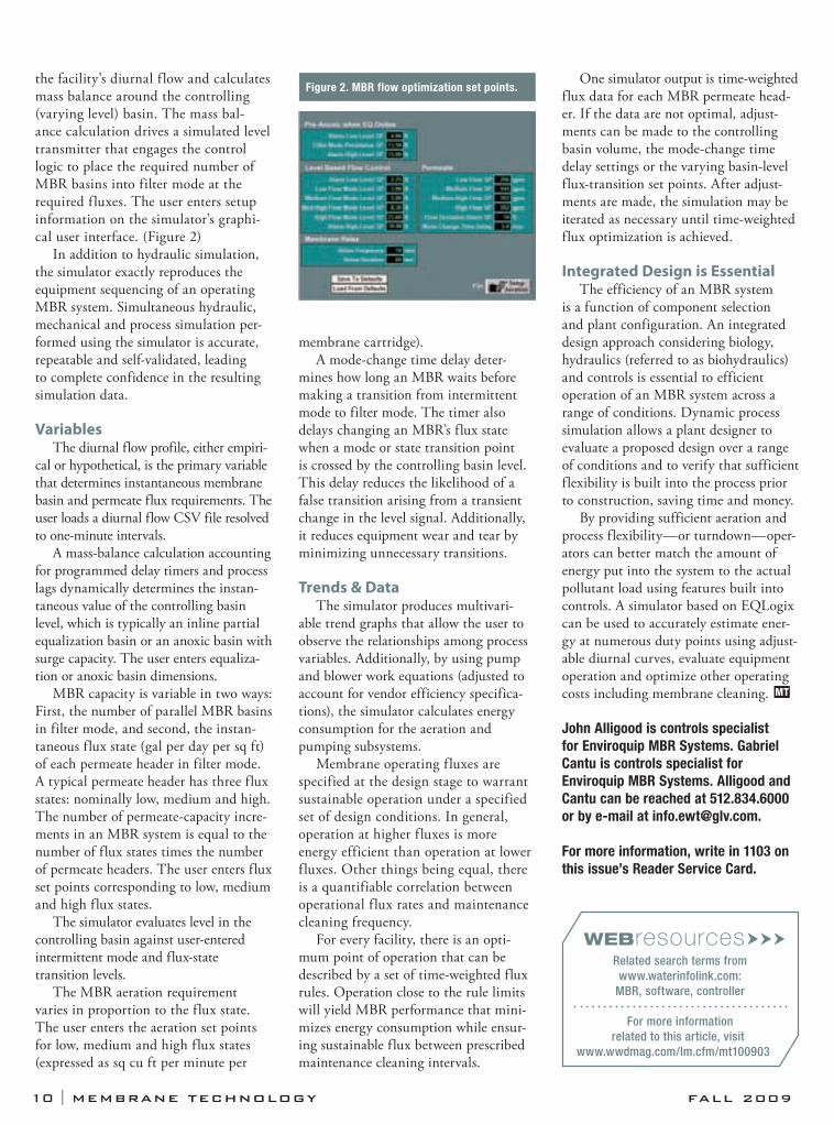
the facility’s diurnal f low and calculates mass balance around the controlling (varying level) basin. The mass bal-ance calculation drives a simulated level transmitter that engages the control logic to place the required number of MBR basins into filter mode at the required f luxes. The user enters setup information on the simulator’s graphi-cal user interface. (Figure 2)
In addition to hydraulic simulation, the simulator exactly reproduces the equipment sequencing of an operating MBR system. Simultaneous hydraulic, mechanical and process simulation per-formed using the simulator is accurate, repeatable and self-validated, leading to complete confidence in the resulting simulation data.
VariablesThe diurnal flow profile, either empiri-
cal or hypothetical, is the primary variable that determines instantaneous membrane basin and permeate flux requirements. The user loads a diurnal flow CSV file resolved to one-minute intervals.
A mass-balance calculation accounting for programmed delay timers and process lags dynamically determines the instan-taneous value of the controlling basin level, which is typically an inline partial equalization basin or an anoxic basin with surge capacity. The user enters equaliza-tion or anoxic basin dimensions.
MBR capacity is variable in two ways: First, the number of parallel MBR basins in filter mode, and second, the instan-taneous flux state (gal per day per sq ft) of each permeate header in filter mode. A typical permeate header has three flux states: nominally low, medium and high. The number of permeate-capacity incre-ments in an MBR system is equal to the number of flux states times the number of permeate headers. The user enters flux set points corresponding to low, medium and high flux states.
The simulator evaluates level in the controlling basin against user-entered intermittent mode and flux-state transition levels.
The MBR aeration requirement varies in proportion to the flux state. The user enters the aeration set points for low, medium and high flux states (expressed as sq cu ft per minute per
membrane cartridge).A mode-change time delay deter-
mines how long an MBR waits before making a transition from intermittent mode to filter mode. The timer also delays changing an MBR’s flux state when a mode or state transition point is crossed by the controlling basin level. This delay reduces the likelihood of a false transition arising from a transient change in the level signal. Additionally, it reduces equipment wear and tear by minimizing unnecessary transitions.
Trends & DataThe simulator produces multivari-
able trend graphs that allow the user to observe the relationships among process variables. Additionally, by using pump and blower work equations (adjusted to account for vendor efficiency specifica-tions), the simulator calculates energy consumption for the aeration and pumping subsystems.
Membrane operating f luxes are specified at the design stage to warrant sustainable operation under a specified set of design conditions. In general, operation at higher f luxes is more energy efficient than operation at lower f luxes. Other things being equal, there is a quantifiable correlation between operational f lux rates and maintenance cleaning frequency.
For every facility, there is an opti-mum point of operation that can be described by a set of time-weighted flux rules. Operation close to the rule limits will yield MBR performance that mini-mizes energy consumption while ensur-ing sustainable flux between prescribed maintenance cleaning intervals.
One simulator output is time-weighted flux data for each MBR permeate head-er. If the data are not optimal, adjust-ments can be made to the controlling basin volume, the mode-change time delay settings or the varying basin-level flux-transition set points. After adjust-ments are made, the simulation may be iterated as necessary until time-weighted flux optimization is achieved.
Integrated Design is EssentialThe efficiency of an MBR system
is a function of component selection and plant configuration. An integrated design approach considering biology, hydraulics (referred to as biohydraulics) and controls is essential to efficient operation of an MBR system across a range of conditions. Dynamic process simulation allows a plant designer to evaluate a proposed design over a range of conditions and to verify that sufficient flexibility is built into the process prior to construction, saving time and money.
By providing sufficient aeration and process flexibility—or turndown—oper-ators can better match the amount of energy put into the system to the actual pollutant load using features built into controls. A simulator based on EQLogix can be used to accurately estimate ener-gy at numerous duty points using adjust-able diurnal curves, evaluate equipment operation and optimize other operating costs including membrane cleaning. MT
John Alligood is controls specialist
for Enviroquip MBR Systems. Gabriel
Cantu is controls specialist for
Enviroquip MBR Systems. Alligood and
Cantu can be reached at 512.834.6000
or by e-mail at [email protected].
For more information, write in 1103 on
this issue’s Reader Service Card.
WEBresourcesRelated search terms from
www.waterinfolink.com:
MBR, software, controller
For more information
related to this article, visit
www.wwdmag.com/lm.cfm/mt100903
10 I MEMBRANE TECHNOLOGY FALL 2009
Figure 2. MBR flow optimization set points.

Increasingly, wastewater treatment facilities are adopting membrane bioreactors (MBRs), mostly made of
submerged membrane modules. While submerged MBRs offer significant advantages, there is growing demand for more environmentally friendly cleaning of the modules.
The need for improved cleaning is the driving force behind the development of the new Bio-Cel modules, which permit chemical-free cleaning through a mechanical cleaning process that uses a beaded granulate and achieves a signifi-cant enhancement of flux. The Bio-Cel solution has been successfully tested in a pilot unit in collaboration with Darmstadt University of Technology.
Effluent Quality Reigns MBRs combine classic biological
wastewater treatment with membrane technology. The biomass is separated from the cleaned wastewater by means of membranes, usually ultrafiltration or microfiltration. This method provides a significant advantage: The membrane acts as a barrier to biomass, particles and bacteria, which leads to substantial improvement in effluent quality when compared to conventional, purely bio-logical techniques in terms of solids and hygienic parameters.
In addition, combining biological and membrane technology increases the biomass concentration in the activated sludge tank. As a result, capacity can be increased and footprint decreased by converting a traditional activated-sludge plant to an MBR. Additional space is gained because the final sedimentation stage can be eliminated. Furthermore, the discharge from an MBR plant is
essentially free of solids, making MBR ideal for supplementary treatment steps with reverse osmosis or nanofiltration as well as ultraviolet or ozone.
Overcoming Braiding & SiltingThe Bio-Cel module, developed by
Microdyn-Nadir GmbH, combines the benefits of flat-sheet membranes and hollow-fiber modules. This space-saving module, based on a back-flushable flat-sheet membrane, is insensitive to braiding and sludge deposits. It requires only a simple pretreatment of the feed flow and facilitates extended operation between cleaning cycles. Yet, even with this design, periodic intensive cleaning with chemicals is still needed.
Cleaning of the membrane modules is required to remove the deposits—oth-erwise they will reduce the membrane’s permeability during operation. There are two types of deposits—scaling and fouling—each requiring suitable clean-ing methods. Scaling refers to inorganic deposits, usually calcium carbonate or ferric salts. Cleaning with organic acids (e.g., citric, formic or acetic) removes these. The organic acids are not objec-tionable environmentally because the spent cleaning solutions can be disposed of with the help of membrane biology.
In contrast, fouling is caused by organic deposits, which is the reason it is often called biofouling. Fouling can be eliminated with oxidants like hydro-gen peroxide or sodium hypochlorite
By Dr. Stefan Krause & Barbara Zimmermann
Mechanical cleaning process removes membrane deposits, enhances flux
The Bio-Cel module saves space and allows for
extended operation between cleaning cycles.
MEMBRANE TECHNOLOGY I 11
Chemical-Free Cleaning
Granulate
Bio-cell
Module
•technical article
(NaOCl). In MBR plants, chlorine has become the norm for removing fouling due to its excellent cleaning efficiency. Unfortunately, it is used in high concentrations—up to 2,000 mg/L in some cases—that cause the formation of large quantities of AOX compounds. AOX is a sum parameter for so-called “adsorbable organic halogen” com-pounds, which are classified as environ-mentally harmful substances.
Although MBR technology is, in principle, a very eco-friendly process as far as membrane cleaning is concerned, it does have this ecological disadvantage.
Clean & Green In a quest to eliminate this ecologi-
cal drawback, a study was conducted to determine the Bio-Cel module’s suitability for chemical-free cleaning in activated sludge without impairing the effluent quality of the membrane. Previous trials confirmed the module could be in use for more than one year
without requiring intensive cleaning in a chemical bath. Chemical back-flushing in an activated-sludge tank is adequate; however, the new study revealed that permeability is lost despite back-flushing with chemicals and intensive cleaning is unavoidable sooner or later.
The investigation into chemical-free cleaning of Bio-Cel modules was based on the premise that, by mechanical means, incipient deposits on the mem-brane can be prevented from forming or deposits already present can be continu-ously removed. To produce the mechani-cal cleaning action, plastic granulate was selected. The granulate was to flow upward between the membrane pockets, propelled by the aeration essential to operate the modules. This required the granulate density to be slightly heavier than the activated sludge and thus able to settle outside the module; it could not be so heavy, however, that it could not be whirled up again and conveyed to the top by the aeration underneath the module.
Mechanical vs. Chemical The study utilized two Bio-Cel mod-
ules, each with a membrane area of 10 sq meters, installed in two parallel filtration chambers on a pilot plant scale and under identical conditions. One of the Bio-Cel modules, based on a back-flushable flat-sheet membrane module, was operated conventionally in activated sludge without adding granulate, while the other Bio-Cel module was required to clean a mixture
•technical article
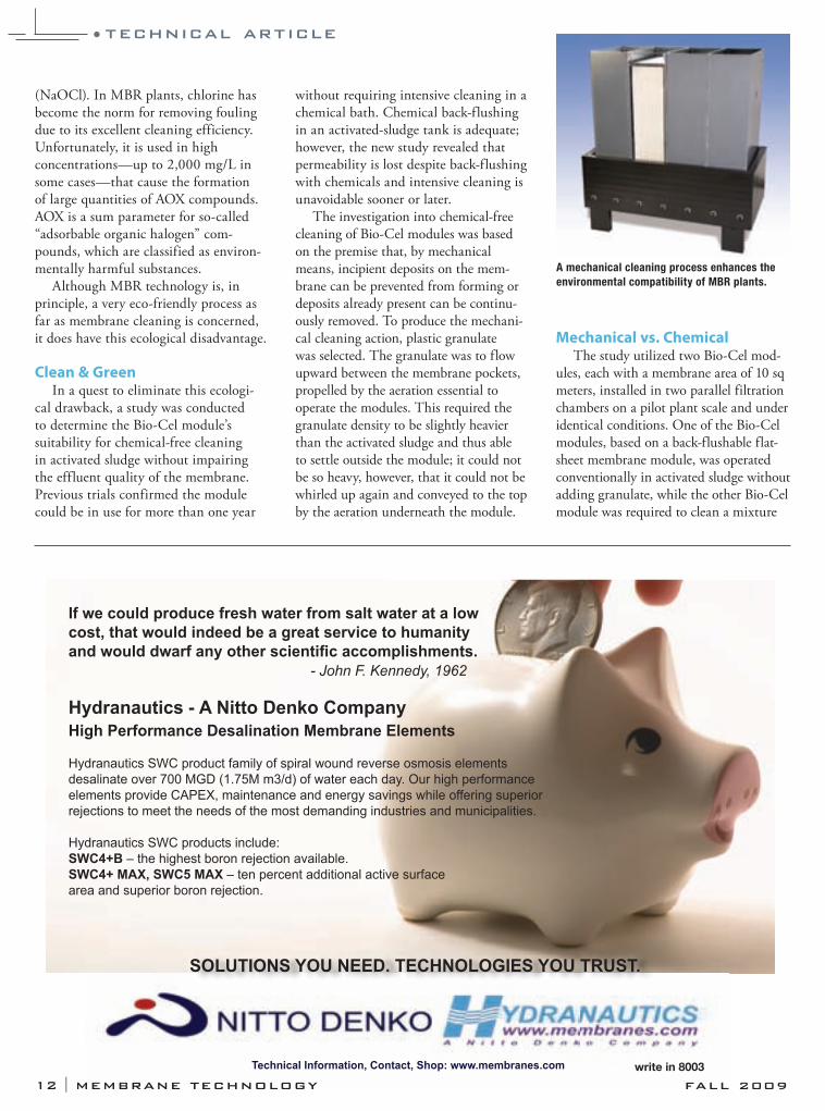
A mechanical cleaning process enhances the
environmental compatibility of MBR plants.
Technical Information, Contact, Shop: www.membranes.com
If we could produce fresh water from salt water at a lowcost, that would indeed be a great service to humanity and would dwarf any other scienti c accomplishments. - John F. Kennedy, 1962
Hydranautics - A Nitto Denko CompanyHigh Performance Desalination Membrane Elements
Hydranautics SWC product family of spiral wound reverse osmosis elementsdesalinate over 700 MGD (1.75M m3/d) of water each day. Our high performanceelements provide CAPEX, maintenance and energy savings while offering superior rejections to meet the needs of the most demanding industries and municipalities.
Hydranautics SWC products include:SWC4+B – the highest boron rejection available.SWC4+ MAX, SWC5 MAX – ten percent additional active surface area and superior boron rejection.
SOLUTIONS YOU NEED. TECHNOLOGIES YOU TRUST.
write in 8003
12 I MEMBRANE TECHNOLOGY FALL 2009
of sludge and granulate. Both modules were set to a flux of
15 L/sq meter/hr for the first three months. After around 70 days in service, the permeability of the reference module had fallen to approximately 40% of the initial value, whereas the mechanical cleaning process (MCP) module had not yet lost any of its permeability. The module without granulate was then maintained at a constant permeability by introducing intermediate cleaning (back-flushing with NaOCl).
In the next trial phase, the flux of the module with granulate was increased to 40 L/sq m/hr. This high flux eventually triggered a reduction in permeability. The rate was then kept constant at 30 L/sq m/hr for a period of several weeks. The Bio-Cel MCP module has been cleaning without chemicals throughout the trial (700 days and counting).
In a subsequent test, granulate was added to the activated sludge in the reference module. After seven days, this
Bio-Cel module had likewise regained its original permeability. This shows that even subsequent cleaning with granulate has the desired effect on the modules.
Granulate Process The study findings demonstrate that
the Bio-Cel module can be cleaned mechanically by adding granulate to the activated sludge; therefore, chemical-free cleaning is possible. The use of a Bio-Cel MCP keeps the permeability—and conse-quently the performance—of the module at a constant level while increasing the hydraulic flux. Furthermore, the MCP is suitable for external module cleaning if the membrane is already fouled.
In addition, the mechanical cleaning process with Bio-Cel modules enhances the environmental compatibility of MBR plants. Problems with AOX compounds will also be minimized. The Bio-Cel MCP will also improve MBR plant availability and pave the way for the construction of even more compact and
efficient facilities due to the higher aver-age flux operation. MT
Dr. Stefan Krause is manager,
MBR applications, for Microdyn-
Nadir GmbH, Wiesbaden/Germany.
Krause can be reached by e-mail at
Barbara Zimmermann is manager,
MBR applications, for Microdyn-Nadir
GmbH, Wiesbaden/Germany.
For more information, write in 1104
on this issue’s Reader Service Card.
WEBresourcesRelated search terms from
www.waterinfolink.com:
submerged MBR, cleaning, chemicals
For more information related to this article,
visit www.wwdmag.com/lm.cfm/mt100904
•technical article
write in 8005
MEMBRANE TECHNOLOGY I 13

In 2005, Belterra, Texas, a residen-tial development in Hays County, southwest of Austin, applied to the
Texas Commission on Environmental Quality (TCEQ) for a surface water discharge permit. Hays County Water Control & Improvement District No. 1 provides water and wastewater service to the development and is responsible for the permitting. The point of discharge is in the Barton Springs segment of the Edwards Aquifer. Barton Springs pro-vides year-round recreational swimming in the heart of Austin and is home to the endangered Barton Springs Salamander.
Obtaining the discharge permit was a process that put development interests in Hays County against environmental interests in the region. Entities in oppo-sition include Austin, Hays County, the Barton Springs Edwards Aquifer Conservation District, Hays Trinity Groundwater Conservation District, Lower Colorado River Authority (LCRA), Save Our Springs Alliance and Bear Creek Home Owners Association.
Planning for GrowthBelterra began development in 2001,
and the district retained CMA Eng., Dripping Springs, Texas, to provide engineering services, wastewater permit-ting and facility design. CMA applied for and received a TCEQ permit for wastewater facilities that included a conventional activated sludge treatment plant and a 35-acre subsurface drip
irrigation system for eff luent disposal. This permit was for 150,000 gal per
day (gpd) and was intended to serve the early phases of the development. Further, the initial permit would allow the district to determine whether sub-surface drip irrigation was a workable alternative for wastewater disposal for full buildout (approximately 2,400 living unit equivalents).
As the population of Belterra con-tinued to grow, it became clear that additional wastewater treatment capacity would be needed and that drip irrigation could not reasonably satisfy the needs. Planning began to increase the capac-ity of the treatment plants to 500,000 gpd, with an intermittent discharge of 350,000 gpd into Bear Creek. Meetings were held with the TCEQ permitting team to discuss probable effluent stan-dards. The phosphorous limit is a major issue in permitting.
Permitting ObjectionsThe district’s counsel, Barrett &
Smith, Austin, Texas, and its engineer both counseled that given the size of the development, it would be in the district’s interest to look at alternatives such as increasing the subsurface drip application rate or direct discharge with a combined beneficial reuse option. The district’s goal was to reuse the treated effluent on the development’s open space and then have the option to discharge directly into the creek when reuse is not
possible (wet periods, frozen ground, etc.). This was a creative and novel approach in this area of Texas.
When TCEQ judges an application to be administratively complete, adja-cent landowners are notified and the notice is published in local newspapers. As the notices were received, the oppo-sition filed protest letters demanding that TCEQ not issue the permit and if necessary, be restrained from issuing the permit. The protestors retained lawyers, scientists and engineers to bolster their case. Their protests cited decisions on similar matters and invoked the usual calamitous scenarios of algae blooms and the dangers associated with wastewaters contaminated by pharmaceuticals and personal care products.
One landowner’s property, close to Belterra, included a pond in Bear Creek that provided contact recreation and fishing opportunities. Further downstream, concerns over the Barton Springs Salamander and the water qual-ity in Barton Springs Pool were raised by the protestors. Records from a U.S. Geological Survey gauging station at the discharge of Barton Springs measured the minimum flow as 9 million gal per day (mgd). The average flow is more than 30 mgd, and the maximumrecorded flow is 85 mgd.
The district’s counsel, litigators, engi-neer and other retained scientists and engineers prepared for legal proceedings and to counter protestor claims. The
By Calvin Patterson & Robert P. Callegari
•case study
14 I MEMBRANE TECHNOLOGY FALL 2009
MBRs prove to be a must in meeting stringent surface water discharge limits in Texas
Downstream Defenders
The Edwards Aquifer, home to endangered salamander,
was the focal point of the negotiations in Hays County.
MEMBRANE TECHNOLOGY I 15
technical team consisted of groundwater and surface water hydrologists, a stream modeler and treatment process and design engineers.
The Mediation ProcessThe probable effluent standards and
capacity of the plant strongly indicated that the emerging technology of MBRs would be the best treatment process for the proposed treatment plant. Enhanced biological phosphorous removal (EBPR) would be employed in the plant to con-trol total phosphorus (TP).
A letter was sent to TCEQ requesting a TP limit of 0.5 mg/L. A draft permit was issued by TCEQ in April 2007, with the following limits on the daily concen-tration of:
Carbonaceous BOD: 5 mg/L• TSS: 5 mg/L• Ammonia: 2 mg/L• TP: 0.15 mg/L •
Belterra requested that the permit application be sent to the State Office of Administrative Hearings (SOAH). SOAH steps in when there is sufficient public protest of a state agency’s pro-posed action to essentially take the direct responsibility for decision making out of the hands of the agency. The operating rules of SOAH are similar to those of a law court. There are two administrative law judges. If negotiations fail to resolve the issues, SOAH will conduct an evidentiary hearing.
All the members of the opposing tech-nical teams submitted direct testimony in the form of a written report on their exper-tise and analysis of the issues. There are depositions of all persons to be witnesses and/or offer direct testimony. Discovery is involved, in which all relevant documents assembled by witnesses are copied and made available to the opposition.
Mediation negotiations between the opposing sides began in June 2008. An evidentiary hearing was scheduled for July. The hearing would be canceled if the negotiations were successful. The negotiations did not resolve all of the issues; however, a consent agreement was reached between the applicants and some of the opposition protestors.
The evidentiary hearing took place during the week of July 13, 2008. About 30 people participated in and observed the proceedings for five days.
In the aftermath of the hearing, both administrative law judges recommended to the TCEQ commissioners that the permit be issued. The commissioners agreed to issue the permit with the pro-viso that the entire consent agreement be incorporated into the permit.
Final Agreement & Outcome The agreement included the follow-
ing 10 points:1. A wastewater treatment plant with
MBR technology;2. Total nitrogen in the effluent lim-
ited to 6 mg/L;3. The applicant will continue to
dispose of 150,000 gpd via drip irrigation;
4. The applicant will apply for a Chapter 201 Beneficial Use Authorization to irrigate 201 acres in Belterra;
5. The applicant shall construct 5,250,000 gal of effluent holding ponds;
6. The daily discharge shall not exceed 350,000 gpd, limited to times when the irrigated acreage is saturated and the holding pond is full and/or Bear Creek is flowing at or above 14 cu ft per second;
7. The treatment system be limited to Belterra;
8. Class A operator;9. An exhaustive stream survey
conducted for 12 months prior to any discharge and 18 months thereafter; and
10. The applicant shall use ultra violet light for disinfection of the treated effluent.
Both parties agreed to the first item in the consent agreement, which makes MBRs an absolute necessity in Hays County. Proposals for supplying the membrane equipment were accepted from three bidders in 2009. The win-ning proposal of $1,425,000 is roughly equal to Belterra’s legal and administra-tive cost of obtaining the permit.
The water quality downstream of Belterra is protected in full measure by the most stringent surface water dis-charge permit limits in Texas. The per-mit ensures beneficial reuse and water conservation in Belterra. MT
Calvin Patterson, Ph.D., P.E., is a
consulting engineer. Patterson can be
reached at 512.343.7375 or by e-mail at
Robert P. Callegari, P.E., is principal
with CMA Eng., Inc. Callegari can be
reached at 512.894.3230 or by e-mail at
For more information, write in 1105 on
this issue’s Reader Service Card.
WEBresourcesRelated search terms from
www.waterinfolink.com:
MBRs, reuse, surface water
For more information related to this article,
visit www.wwdmag.com/lm.cfm/mt100905
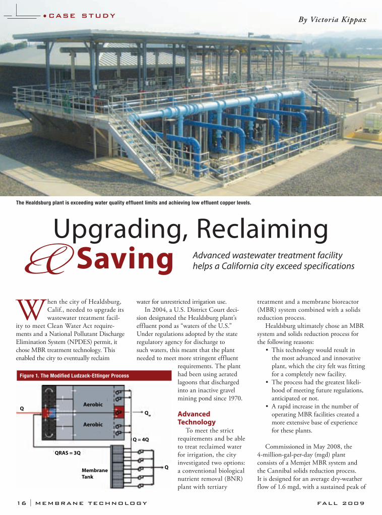
When the city of Healdsburg, Calif., needed to upgrade its wastewater treatment facil-
ity to meet Clean Water Act require-ments and a National Pollutant Discharge Elimination System (NPDES) permit, it chose MBR treatment technology. This enabled the city to eventually reclaim
water for unrestricted irrigation use.In 2004, a U.S. District Court deci-
sion designated the Healdsburg plant’s effluent pond as “waters of the U.S.” Under regulations adopted by the state regulatory agency for discharge to such waters, this meant that the plant needed to meet more stringent effluent
requirements. The plant had been using aerated lagoons that discharged into an inactive gravel mining pond since 1970.
Advanced Technology
To meet the strict requirements and be able to treat reclaimed water for irrigation, the city investigated two options: a conventional biological nutrient removal (BNR) plant with tertiary
treatment and a membrane bioreactor (MBR) system combined with a solids reduction process.
Healdsburg ultimately chose an MBR system and solids reduction process for the following reasons:
This technology would result in • the most advanced and innovative plant, which the city felt was fitting for a completely new facility.The process had the greatest likeli-• hood of meeting future regulations, anticipated or not.A rapid increase in the number of • operating MBR facilities created a more extensive base of experience for these plants.
Commissioned in May 2008, the 4-million-gal-per-day (mgd) plant consists of a Memjet MBR system and the Cannibal solids reduction process. It is designed for an average dry-weather flow of 1.6 mgd, with a sustained peak of
Upgrading, Reclaiming& Saving
By Victoria Kippax•case study
Membrane Tank
QRAS = 3Q
Q = 4Q
Qw
Q
Aerobic
Aerobic
Q
Figure 1. The Modified Ludzack-Ettinger Process
16 I MEMBRANE TECHNOLOGY FALL 2009
The Healdsburg plant is exceeding water quality effluent limits and achieving low effluent copper levels.
Advanced wastewater treatment facility helps a California city exceed specifications
For better filtration, you need more fiber.SpinTek’s advanced Hollow Fiber (HF) Membrane technology is a simple,powerful ultrafiltration solution. SpinTek’s HF membranes provide a highsurface area for compact filtration systems with space saving advantages andhigher filtration rates.
POTTING SERVICES SpinTek can provide potted modules up to 4.5" [114mm]as a single module without interspacing of fiber sections.
HIGH PERFORMANCE Clear water fluxes of up to 70gfd[119lmh] are possible. Operating pH range is 2-12,max. temperature is 150° F (66°C) and max. pressure is100 psig (695 kPa). A HOST OF CONFIGURATIONS SpinTek HF membranesare available as continuous rolls or precut, wet or fully dry
for potting, and in a variety of materials (PS, PES, PVDF, PAN). Available
diameters range from 0.6mm to 1.2mm and lenghts can be up to 72" [1.829]m.Step up to Megafiltration Visit us on the web at www.spintek.com, orcall 714-236-9196 for more information.
10863 Portal Drive, Los Alamitos, CA 90720 USATel: (714) 236-9190 | Fax: (714) 236-9196 |www.spintek.com
Hollow fiber membranes can beassembled into bundles
4 mgd. One of the old treatment lagoons is now used as an equalization basin during winter storm events. This allowed the city to build the treatment plant with a smaller peak flow than it would have otherwise needed to accommodate peak flows. The equalization volume is designed for a one-in-100-year storm flow.
Process OverviewThe MBR system consists of two
parallel biological trains configured in a Modified Ludzack-Ettinger (MLE) process (Figure 1) for biological nutri-ent removal, plus five membrane tanks with a common overflow weir. Each membrane tank is equipped with 144 immersed membrane modules, with additional space for up to 160 modules.
The membrane operating system was designed so that one tank can be taken out of service in all flow conditions for maintenance or cleaning. Filtrate is drawn through the membranes by applying a suction pressure from a rotary-lobe positive displacement pump, while the suspended solids and bacteria are
retained in the mixed liquor and over-flowed back into the biological system.
The filtrate flows through low-pres-sure, high-intensity UV lamps and then to discharge. At some point in the future, the plant effluent will be reclaimed for unrestricted use.
ResultsBy combining the solids reduction pro-
cess with the MBR, the city expects to pro-long membrane life because of the solids reduction process enhanced solids removal. The facility uses fine screens (<250 μm) to remove solids which can damage the mem-brane; their accumulation decreases the effective membrane surface area.
The solids reduction process started up in December 2008, and the city expects to realize a 50% to 75% reduction in bio-solids yield. The projected yield will result in significant savings in sludge handling and hauling costs. To date, the Healdsburg plant is exceeding the water quality efflu-ent limits in its NPDES permit and achieving very low effluent copper levels (<0.01 mg/L) in the region.
“The MBR/solids reduction system has well positioned the city to market and recycle its high-quality effluent for beneficial reuse,” said Jim Flugum, senior civil engineer at the city of Healdsburg Public Works Department, “and will allow us to meet more stringent water quality regulations in the future.” MT
Victoria Kippax is MBR product
manager for Siemens Water
Technologies Corp. Kippax can be
reached at 262.521.8487 or by e-mail
For more information, write in 1106 on
this issue’s Reader Service Card.
WEBresourcesRelated search terms from
www.waterinfolink.com:
MBR, solids reduction, reclaimed water
For more information
related to this article, visit
www.wwdmag.com/lm.cfm/wd100906
•case study
MEMBRANE TECHNOLOGY I 17
write in 8006
18 I MEMBRANE TECHNOLOGY FALL 200918 I MEMBRANE TECHNOLOGY FALL 2009
Compiled by Clare Pierson
Clare Pierson: Black & Veatch con-ducted a ceramic membrane research study in early 2009. Why did the com-pany do this, and what were the results?
Jonathan Clement: This research study was a global initiative with the intent of looking at ceramic membranes in the water market, including water reuse and drinking water treatment, in response to a lot of interest from our clients.
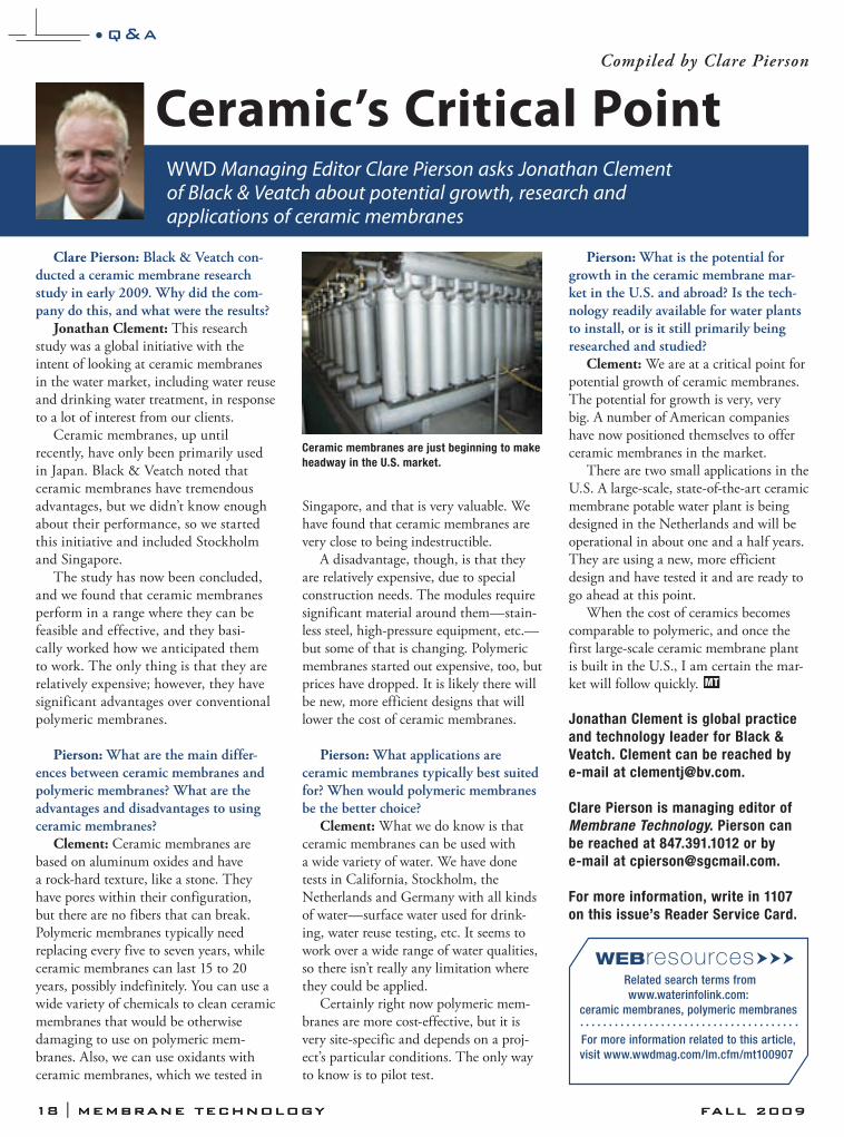
Ceramic membranes, up until recently, have only been primarily used in Japan. Black & Veatch noted that ceramic membranes have tremendous advantages, but we didn’t know enough about their performance, so we started this initiative and included Stockholm and Singapore.
The study has now been concluded, and we found that ceramic membranes perform in a range where they can be feasible and effective, and they basi-cally worked how we anticipated them to work. The only thing is that they are relatively expensive; however, they have significant advantages over conventional polymeric membranes.
Pierson: What are the main differ-ences between ceramic membranes and polymeric membranes? What are the advantages and disadvantages to using ceramic membranes?
Clement: Ceramic membranes are based on aluminum oxides and have a rock-hard texture, like a stone. They have pores within their configuration, but there are no fibers that can break. Polymeric membranes typically need replacing every five to seven years, while ceramic membranes can last 15 to 20 years, possibly indefinitely. You can use a wide variety of chemicals to clean ceramic membranes that would be otherwise damaging to use on polymeric mem-branes. Also, we can use oxidants with ceramic membranes, which we tested in
Singapore, and that is very valuable. We have found that ceramic membranes are very close to being indestructible.
A disadvantage, though, is that they are relatively expensive, due to special construction needs. The modules require significant material around them—stain-less steel, high-pressure equipment, etc.—but some of that is changing. Polymeric membranes started out expensive, too, but prices have dropped. It is likely there will be new, more efficient designs that will lower the cost of ceramic membranes.
Pierson: What applications are ceramic membranes typically best suited for? When would polymeric membranes be the better choice?
Clement: What we do know is that ceramic membranes can be used with a wide variety of water. We have done tests in California, Stockholm, the Netherlands and Germany with all kinds of water—surface water used for drink-ing, water reuse testing, etc. It seems to work over a wide range of water qualities, so there isn’t really any limitation where they could be applied.
Certainly right now polymeric mem-branes are more cost-effective, but it is very site-specific and depends on a proj-ect’s particular conditions. The only way to know is to pilot test.
Pierson: What is the potential for growth in the ceramic membrane mar-ket in the U.S. and abroad? Is the tech-nology readily available for water plants to install, or is it still primarily being researched and studied?
Clement: We are at a critical point for potential growth of ceramic membranes. The potential for growth is very, very big. A number of American companies have now positioned themselves to offer ceramic membranes in the market.
There are two small applications in the U.S. A large-scale, state-of-the-art ceramic membrane potable water plant is being designed in the Netherlands and will be operational in about one and a half years. They are using a new, more efficient design and have tested it and are ready to go ahead at this point.
When the cost of ceramics becomes comparable to polymeric, and once the first large-scale ceramic membrane plant is built in the U.S., I am certain the mar-ket will follow quickly. MT
Jonathan Clement is global practice
and technology leader for Black &
Veatch. Clement can be reached by
e-mail at [email protected].
Clare Pierson is managing editor of
Membrane Technology. Pierson can
be reached at 847.391.1012 or by
e-mail at [email protected].
For more information, write in 1107
on this issue’s Reader Service Card.
WWD Managing Editor Clare Pierson asks Jonathan Clement of Black & Veatch about potential growth, research and applications of ceramic membranes
Ceramic’s Critical Point
•q&a
WEBresourcesRelated search terms from
www.waterinfolink.com:
ceramic membranes, polymeric membranes
For more information related to this article,
visit www.wwdmag.com/lm.cfm/mt100907
Ceramic membranes are just beginning to make
headway in the U.S. market.
MEMBRANE TECHNOLOGY I 19MEMBRANE TECHNOLOGY I 19
SUPPORTING AFFILIATIONS & PARTNERSHIPS
InternationalDesalination Association
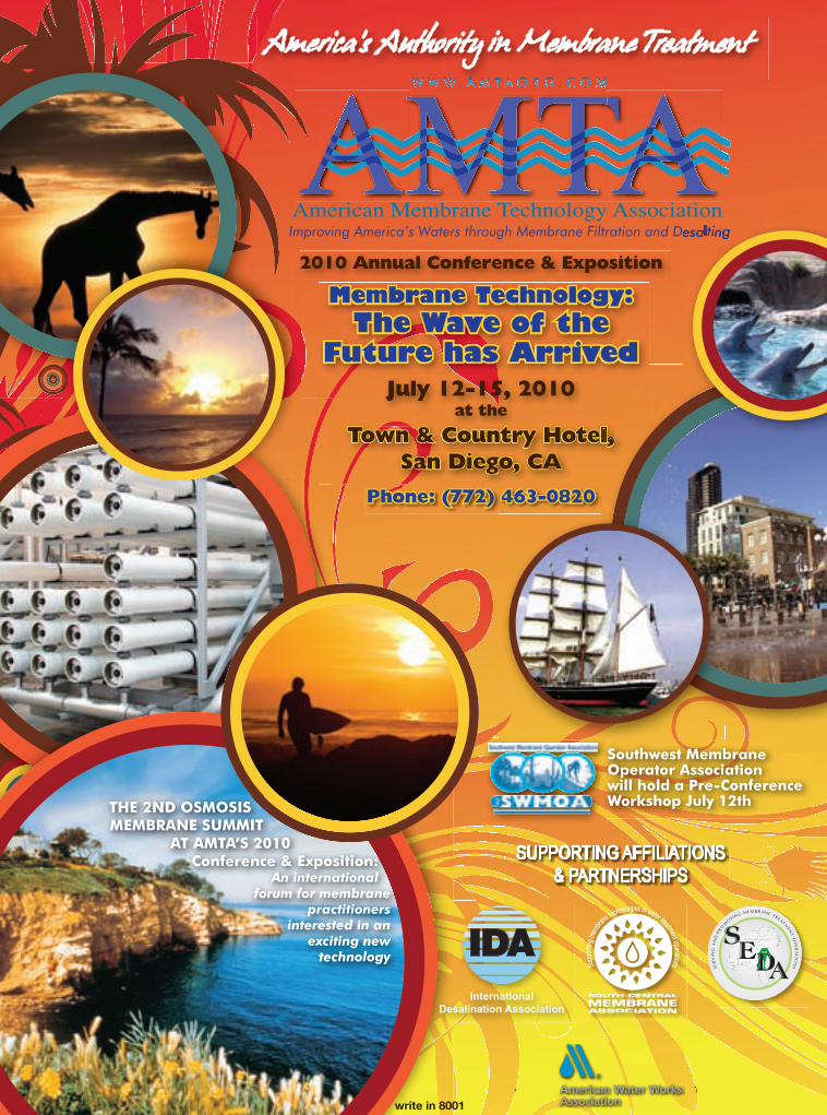
2010 Annual Conference & Exposition
Membrane Technology: The Wave of the
Future has ArrivedJuly 12-15, 2010
at the
Town & Country Hotel,San Diego, CA
Southwest MembraneOperator Associationwill hold a Pre-ConferenceWorkshop July 12th
Phone: (772) 463-0820
THE 2ND OSMOSIS MEMBRANE SUMMIT
AT AMTA’S 2010Conference & Exposition:
An internationalforum for membrane
practitioners interested in an
exciting new technology
write in 8001
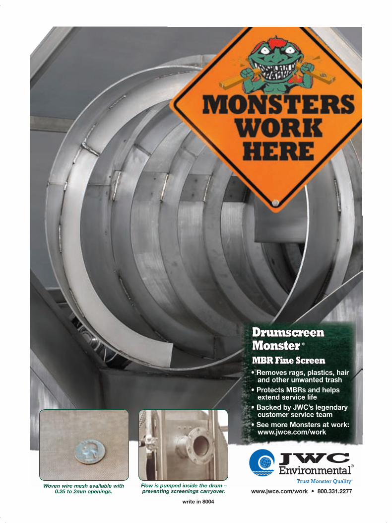
Woven wire mesh available with0.25 to 2mm openings.
Flow is pumped inside the drum – preventing screenings carryover.
www.jwce.com/work
Drumscreen MonsterMBR Fine Screen
®
Write in xxxwrite in 8004


![TUBES - CV HW...PRODUIT CV10#200 018 0C1 ST9010 CV10#200 018 Z ( v o } u } D } o U , µ µ ~ î ì ì E } u [ o u v ~ ì í ô 0C1 Z ( v } ] v ] µ v o o µ ] r } µ](https://img.dokumen.tips/doc/110x75/60e5456d70cbce760039cda8/tubes-cv-hw-produit-cv10200-018-0c1-st9010-cv10200-018-z-v-o-u-d-.jpg)


![Ü. Z Öğretici Metinler – 2 [haber yazıları] [fıkra ...img.eba.gov.tr/114/770/0c1/15c/653/4f4/fe4/9d4/402/7bf/0c0/3f7/294/cae/001... · Bir yazarın herhangi bir konu hakkındaki](https://img.dokumen.tips/doc/110x75/5e07af84ec6e9537dc26e40e/oe-z-retici-metinler-a-2-haber-yazlar-fkra-imgebagovtr1147700c115c6534f4fe49d44027bf0c03f7294cae001.jpg)


