Embed Size (px)
Citation preview

1037087-0001Revision D December 21, 2010
0.74 m Ku-Band Upgradeable Antenna Installation Guide – Model AN6-074P

Copyright © 2006, 2009-2010 Hughes Network Systems, LLC
All rights reserved. This publication and its contents are proprietary to Hughes Network Systems, LLC. No part of this publication may be reproduced in any form or by any means without the written permission of Hughes Network Systems, LLC, 11717 Exploration Lane, Germantown, Maryland 20876.
Hughes Network Systems, LLC has made every effort to ensure the correctness and completeness of the material in this document. Hughes Network Systems, LLC shall not be liable for errors contained herein. The information in this document is subject to change without notice. Hughes Network Systems, LLC makes no warranty of any kind with regard to this material, including, but not limited to, the implied warranties of merchantability and fitness for a particular purpose.
Trademarks
Hughes, HughesNet, and Hughes Network Systems are trademarks of Hughes Network Systems, LLC. All other trademarks are the property of their respective owners.

Contents
Understanding safety alert messages . . . . . . . . . . . . . . . xiMessages concerning personal injury. . . . . . . . . . . . . . . . . . . . . xiMessages concerning property damage . . . . . . . . . . . . . . . . . . . xiSafety symbols . . . . . . . . . . . . . . . . . . . . . . . . . . . . . . . . . . . . . .xii
Additional symbols. . . . . . . . . . . . . . . . . . . . . . . . . . . . . . . . .xiiAntenna installation safety . . . . . . . . . . . . . . . . . . . . . . xiii
Chapter 1Overview . . . . . . . . . . . . . . . . . . . . . . . . . . . . . . . . . . . . . . .1Scope and audience . . . . . . . . . . . . . . . . . . . . . . . . . . . . . . . . . . .1The model AN6-074P antenna . . . . . . . . . . . . . . . . . . . . . . . . . . .2Antenna installation summary . . . . . . . . . . . . . . . . . . . . . . . . . . .3Tasks related to antenna installation . . . . . . . . . . . . . . . . . . . . . .4
Selecting the installation site . . . . . . . . . . . . . . . . . . . . . . . . . .4Installing the antenna mount . . . . . . . . . . . . . . . . . . . . . . . . . .4Installing the IDU. . . . . . . . . . . . . . . . . . . . . . . . . . . . . . . . . . .5Grounding. . . . . . . . . . . . . . . . . . . . . . . . . . . . . . . . . . . . . . . . .5Approved cables . . . . . . . . . . . . . . . . . . . . . . . . . . . . . . . . . . . .5
Chapter 2Antenna parts and recommended tools . . . . . . . . . . . . . .7Antenna kit components . . . . . . . . . . . . . . . . . . . . . . . . . . . . . . . .7
Az/El mount assembly . . . . . . . . . . . . . . . . . . . . . . . . . . . . . . .8Reflector bracket and tilt plate . . . . . . . . . . . . . . . . . . . . . . . . .9Antenna reflector . . . . . . . . . . . . . . . . . . . . . . . . . . . . . . . . . . .9Feed support arm . . . . . . . . . . . . . . . . . . . . . . . . . . . . . . . . . .10Feed horn . . . . . . . . . . . . . . . . . . . . . . . . . . . . . . . . . . . . . . . .10Radio assembly. . . . . . . . . . . . . . . . . . . . . . . . . . . . . . . . . . . .11Vertical shim kit (if required). . . . . . . . . . . . . . . . . . . . . . . . .11
Small hardware parts list . . . . . . . . . . . . . . . . . . . . . . . . . . . . . .12Tools . . . . . . . . . . . . . . . . . . . . . . . . . . . . . . . . . . . . . . . . . . . . . .13
Chapter 3Installing the antenna and radio assembly . . . . . . . . . .15Determining the pointing values . . . . . . . . . . . . . . . . . . . . . . . .15General instructions for assembling the antenna . . . . . . . . . . . .16Installing the reflector bracket and tilt plate. . . . . . . . . . . . . . . .17Installing the antenna reflector . . . . . . . . . . . . . . . . . . . . . . . . . .19
• Contents 1037087-0001 Revision D iii

iv
Installing the feed support arm. . . . . . . . . . . . . . . . . . . . . . . . . .20Installing the feed horn. . . . . . . . . . . . . . . . . . . . . . . . . . . . . . . .21Installing the radio assembly . . . . . . . . . . . . . . . . . . . . . . . . . . .23
Installing a shim for vertical transmit polarization (if required). . . . . . . . . . . . . . . . . . . . . . . . . . . . . . . . . . . . . . .23Installing the radio assembly . . . . . . . . . . . . . . . . . . . . . . . . .26
Mounting the antenna assembly onto the mast pipe. . . . . . . . . .28
Chapter 4Cabling and connections . . . . . . . . . . . . . . . . . . . . . . . . .31Cabling requirements . . . . . . . . . . . . . . . . . . . . . . . . . . . . . . . . .31Routing the IFL cables at the antenna . . . . . . . . . . . . . . . . . . . .32
Routing the transmit cable . . . . . . . . . . . . . . . . . . . . . . . . . . .33Routing the receive cable . . . . . . . . . . . . . . . . . . . . . . . . . . . .33
Connecting the transmit and receive cables . . . . . . . . . . . . . . . .34Connecting the transmit cable . . . . . . . . . . . . . . . . . . . . . . . .34Connecting the receive cable . . . . . . . . . . . . . . . . . . . . . . . . .34
Ground connection . . . . . . . . . . . . . . . . . . . . . . . . . . . . . . . . . . .35
Chapter 5Pointing the antenna . . . . . . . . . . . . . . . . . . . . . . . . . . . .37Antenna pointing safety precautions . . . . . . . . . . . . . . . . . . . . .38Antenna pointing overview . . . . . . . . . . . . . . . . . . . . . . . . . . . .39
Using the SBC software . . . . . . . . . . . . . . . . . . . . . . . . . . . . .39Peaking the signal. . . . . . . . . . . . . . . . . . . . . . . . . . . . . . . . . .39
Prerequisites for antenna pointing . . . . . . . . . . . . . . . . . . . . . . .40Pointing tools . . . . . . . . . . . . . . . . . . . . . . . . . . . . . . . . . . . . . . .40
DAPT . . . . . . . . . . . . . . . . . . . . . . . . . . . . . . . . . . . . . . . . . . .40Installing the DAPT . . . . . . . . . . . . . . . . . . . . . . . . . . . . . .41Understanding the DAPT display. . . . . . . . . . . . . . . . . . . .42
OPI . . . . . . . . . . . . . . . . . . . . . . . . . . . . . . . . . . . . . . . . . . . . .42Installing the OPI . . . . . . . . . . . . . . . . . . . . . . . . . . . . . . . .43
Adjusting the antenna. . . . . . . . . . . . . . . . . . . . . . . . . . . . . . . . .44Setting coarse elevation . . . . . . . . . . . . . . . . . . . . . . . . . . . . . . .45
Fine elevation adjustment. . . . . . . . . . . . . . . . . . . . . . . . . . . .46Receive pointing. . . . . . . . . . . . . . . . . . . . . . . . . . . . . . . . . . . . .47
Initial elevation setting . . . . . . . . . . . . . . . . . . . . . . . . . . . . . .47Setting the tilt angle . . . . . . . . . . . . . . . . . . . . . . . . . . . . . . . .47Setting azimuth. . . . . . . . . . . . . . . . . . . . . . . . . . . . . . . . . . . .49
Checking the azimuth base starting position . . . . . . . . . . .49Coarse azimuth adjustment. . . . . . . . . . . . . . . . . . . . . . . . .50Fine azimuth adjustment. . . . . . . . . . . . . . . . . . . . . . . . . . .51If no signal is present . . . . . . . . . . . . . . . . . . . . . . . . . . . . .51
Peaking the receive signal . . . . . . . . . . . . . . . . . . . . . . . . . . .52
• Contents 1037087-0001 Revision D
Isolating the transmit signal . . . . . . . . . . . . . . . . . . . . . . . . . . . .53Manual ACP test. . . . . . . . . . . . . . . . . . . . . . . . . . . . . . . . . . .53Automatic ACP test . . . . . . . . . . . . . . . . . . . . . . . . . . . . . . . .55
Final steps. . . . . . . . . . . . . . . . . . . . . . . . . . . . . . . . . . . . . . . . . .56Remove the pointing tool . . . . . . . . . . . . . . . . . . . . . . . . . . . .56Weatherproof the cable connections . . . . . . . . . . . . . . . . . . .56Check for safety labels and signs . . . . . . . . . . . . . . . . . . . . . .56Subsequent steps. . . . . . . . . . . . . . . . . . . . . . . . . . . . . . . . . . .56
Acronyms and abbreviations . . . . . . . . . . . . . . . . . . . . .57Index . . . . . . . . . . . . . . . . . . . . . . . . . . . . . . . . . . . . . . . . .59
• Contents 1037087-0001 Revision D v

vi
• Contents 1037087-0001 Revision D
Figures
Chapter 11. The Hughes model AN6-074P satellite antenna. . . . . . . . . . . . . . . . . . . . . . . . . .2
Chapter 22. Az/El mount assembly . . . . . . . . . . . . . . . . . . . . . . . . . . . . . . . . . . . . . . . . . . . . .83. Reflector bracket and tilt plate . . . . . . . . . . . . . . . . . . . . . . . . . . . . . . . . . . . . . . .94. Antenna reflector . . . . . . . . . . . . . . . . . . . . . . . . . . . . . . . . . . . . . . . . . . . . . . . . .95. Feed support arm . . . . . . . . . . . . . . . . . . . . . . . . . . . . . . . . . . . . . . . . . . . . . . . .106. Feed horn . . . . . . . . . . . . . . . . . . . . . . . . . . . . . . . . . . . . . . . . . . . . . . . . . . . . . .107. Radio assembly. . . . . . . . . . . . . . . . . . . . . . . . . . . . . . . . . . . . . . . . . . . . . . . . . .118. Shim for vertical transmit polarization . . . . . . . . . . . . . . . . . . . . . . . . . . . . . . . .11
Chapter 39. Attaching the reflector bracket and tilt plate . . . . . . . . . . . . . . . . . . . . . . . . . . .17
10. Tilt pointer aligned with zero on tilt scale . . . . . . . . . . . . . . . . . . . . . . . . . . . . .1811. Attaching the antenna reflector. . . . . . . . . . . . . . . . . . . . . . . . . . . . . . . . . . . . . .1912. Attaching the feed support arm to the tailpiece . . . . . . . . . . . . . . . . . . . . . . . . .2013. Inserting the O-ring into the feed horn . . . . . . . . . . . . . . . . . . . . . . . . . . . . . . . .2114. Installing the feed horn . . . . . . . . . . . . . . . . . . . . . . . . . . . . . . . . . . . . . . . . . . . .2215. Shim location next to TRIA . . . . . . . . . . . . . . . . . . . . . . . . . . . . . . . . . . . . . . . .2316. Horizontal shim and vertical shim for transmit polarization . . . . . . . . . . . . . . .2417. Direction of TRIA rotation for vertical polarization . . . . . . . . . . . . . . . . . . . . .2518. TRIA position for horizontal and vertical transmit polarization . . . . . . . . . . . .2519. Installing the radio assembly . . . . . . . . . . . . . . . . . . . . . . . . . . . . . . . . . . . . . . .2720. Making sure the mast is plumb. . . . . . . . . . . . . . . . . . . . . . . . . . . . . . . . . . . . . .2821. Installing the Az/El mount assembly . . . . . . . . . . . . . . . . . . . . . . . . . . . . . . . . .2922. Assembled antenna . . . . . . . . . . . . . . . . . . . . . . . . . . . . . . . . . . . . . . . . . . . . . . .30
Chapter 423. Transmit and receive cable configurations . . . . . . . . . . . . . . . . . . . . . . . . . . . . .3224. Transmit connector . . . . . . . . . . . . . . . . . . . . . . . . . . . . . . . . . . . . . . . . . . . . . . .3425. Receive connector. . . . . . . . . . . . . . . . . . . . . . . . . . . . . . . . . . . . . . . . . . . . . . . .35
Chapter 526. DiSEqC Antenna Pointing Tool (DAPT) . . . . . . . . . . . . . . . . . . . . . . . . . . . . . .4027. Installing the DAPT . . . . . . . . . . . . . . . . . . . . . . . . . . . . . . . . . . . . . . . . . . . . . .4128. Outdoor Pointing Interface (OPI) . . . . . . . . . . . . . . . . . . . . . . . . . . . . . . . . . . . .42
• Figures 1037087-0001 Revision D vii

viii
29. Installing the OPI . . . . . . . . . . . . . . . . . . . . . . . . . . . . . . . . . . . . . . . . . . . . . . . .4330. Adjusting azimuth, elevation, and tilt. . . . . . . . . . . . . . . . . . . . . . . . . . . . . . . . .4431. Elevation adjustment rod, adjustment and lockdown nuts, and scale . . . . . . . .4532. Elevation marker. . . . . . . . . . . . . . . . . . . . . . . . . . . . . . . . . . . . . . . . . . . . . . . . .4633. Location of tilt lockdown nuts . . . . . . . . . . . . . . . . . . . . . . . . . . . . . . . . . . . . . .4734. Tilt scale . . . . . . . . . . . . . . . . . . . . . . . . . . . . . . . . . . . . . . . . . . . . . . . . . . . . . . .4835. Checking the azimuth base starting position . . . . . . . . . . . . . . . . . . . . . . . . . . .4936. Az/El canister nuts . . . . . . . . . . . . . . . . . . . . . . . . . . . . . . . . . . . . . . . . . . . . . . .5037. Weatherproofed connection with cable tie (arrow) . . . . . . . . . . . . . . . . . . . . . .56
• Figures 1037087-0001 Revision D

Tables
Chapter 11. Satellite antenna installation summary . . . . . . . . . . . . . . . . . . . . . . . . . . . . . . . . .3
Chapter 22. Small hardware parts . . . . . . . . . . . . . . . . . . . . . . . . . . . . . . . . . . . . . . . . . . . . .123. Tools recommended for installing and pointing the antenna . . . . . . . . . . . . . . .13
Chapter 34. Torque specifications . . . . . . . . . . . . . . . . . . . . . . . . . . . . . . . . . . . . . . . . . . . . .16
• Tables 1037087-0001 Revision D ix

x
• Tables 1037087-0001 Revision D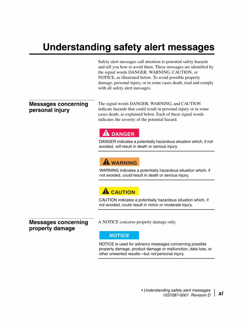
Understanding safety alert messages Safety alert messages call attention to potential safety hazards and tell you how to avoid them. These messages are identified by the signal words DANGER, WARNING, CAUTION, or NOTICE, as illustrated below. To avoid possible property damage, personal injury, or in some cases death, read and comply with all safety alert messages.
Messages concerning personal injury
The signal words DANGER, WARNING, and CAUTION indicate hazards that could result in personal injury or in some cases death, as explained below. Each of these signal words indicates the severity of the potential hazard.
DANGER indicates a potentially hazardous situation which, if not avoided, will result in death or serious injury.
WARNING indicates a potentially hazardous situation which, if not avoided, could result in death or serious injury.
CAUTION indicates a potentially hazardous situation which, if not avoided, could result in minor or moderate injury.
Messages concerning property damage
A NOTICE concerns property damage only.
NOTICE is used for advisory messages concerning possible property damage, product damage or malfunction, data loss, or other unwanted results—but not personal injury.
DANGER
WARNING
CAUTION
NOTICE
• Understanding safety alert messages 1037087-0001 Revision D xi
xii
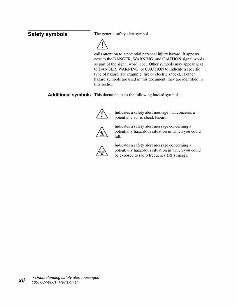
Safety symbols The generic safety alert symbol
calls attention to a potential personal injury hazard. It appears next to the DANGER, WARNING, and CAUTION signal words as part of the signal word label. Other symbols may appear next to DANGER, WARNING, or CAUTION to indicate a specific type of hazard (for example, fire or electric shock). If other hazard symbols are used in this document, they are identified in this section.
Additional symbols This document uses the following hazard symbols:
Indicates a safety alert message that concerns a potential electric shock hazard.
Indicates a safety alert message concerning a potentially hazardous situation in which you could fall.
Indicates a safety alert message concerning a potentially hazardous situation in which you could be exposed to radio frequency (RF) energy.
• Understanding safety alert messages 1037087-0001 Revision D
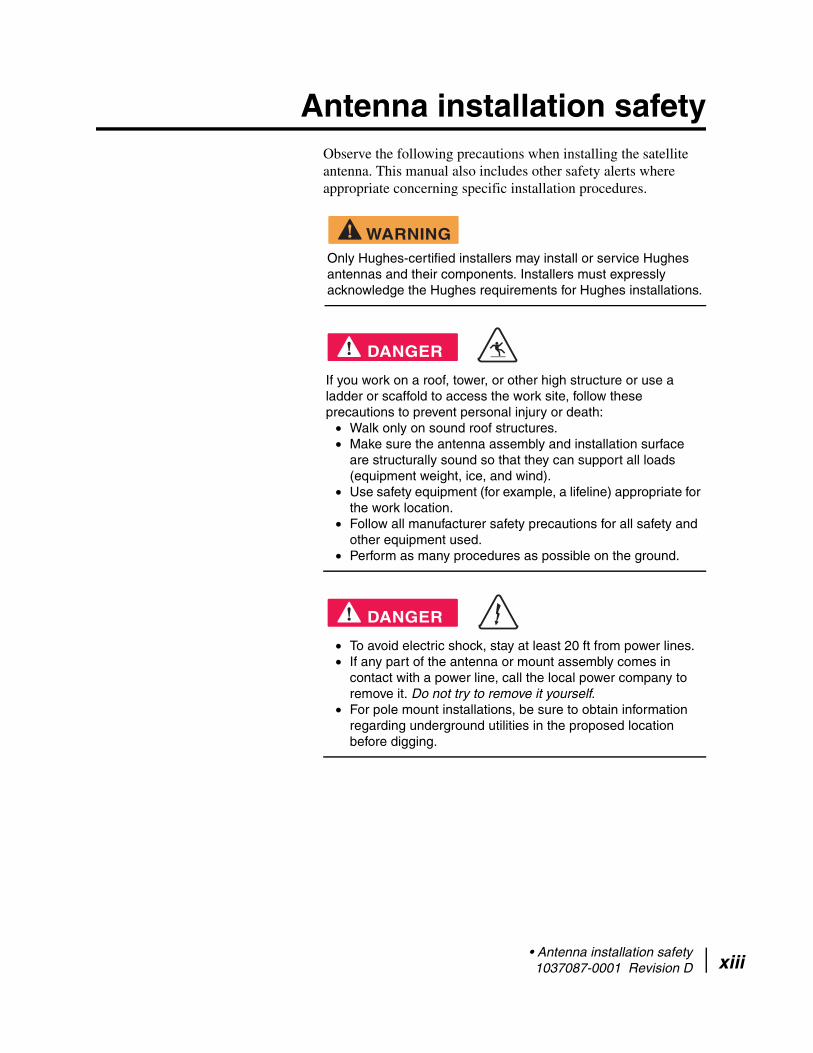
Antenna installation safetyObserve the following precautions when installing the satellite antenna. This manual also includes other safety alerts where appropriate concerning specific installation procedures.
Only Hughes-certified installers may install or service Hughes antennas and their components. Installers must expressly acknowledge the Hughes requirements for Hughes installations.
If you work on a roof, tower, or other high structure or use a ladder or scaffold to access the work site, follow these precautions to prevent personal injury or death:
• Walk only on sound roof structures. • Make sure the antenna assembly and installation surface
are structurally sound so that they can support all loads (equipment weight, ice, and wind).
• Use safety equipment (for example, a lifeline) appropriate for the work location.
• Follow all manufacturer safety precautions for all safety and other equipment used.
• Perform as many procedures as possible on the ground.
• To avoid electric shock, stay at least 20 ft from power lines. • If any part of the antenna or mount assembly comes in
contact with a power line, call the local power company to remove it. Do not try to remove it yourself.
• For pole mount installations, be sure to obtain information regarding underground utilities in the proposed location before digging.
WARNING
DANGER
DANGER
• Antenna installation safety 1037087-0001 Revision D xiii

xiv
Properly ground the antenna assembly in accordance with all local and national electrical codes.
• Do not work in high wind or rain; or if a storm, lightning, or other adverse weather conditions are either present or approaching.
• Do not attempt to assemble, move, or mount the antenna on a windy day. Even a slight wind can unexpectedly create sudden strong forces on the antenna surface.
If the antenna or mount assembly begins to fall during the installation, do not attempt to catch it. Move away and let it fall.
WARNING
WARNING
CAUTION
• Antenna installation safety 1037087-0001 Revision D

Observe these precautions to avoid exposure to RF radiation, a potential safety hazard:
• The antenna must be installed in a location not readily accessible to children and in a manner that prevents human exposure to potentially harmful levels of radiation.
• Antennas mounted in Puerto Rico, the continental United States, or at any site with a greater than 30° elevation angle must be installed such that the lower lip of the antenna reflector is at least 5 ft above any surface upon which a person might be expected to stand, and 3 ft 3 inches from any opening (such as a door or window) in a building or adjacent structure.
• Antennas mounted in Canada, Alaska, Hawaii, or any site with a less than 30° elevation must be installed such that the lower lip of the antenna reflector is at least 5 ft 9 inches above any surface upon which a person might be expected to stand, and 3 ft 3 inches from any opening (such as a door or window) in a building or adjacent structure.
• The antenna must be mounted such that no object that could reasonably be expected to support a person is within 6 ft 7 inches of the edges of a cylindrical space projecting outward from the antenna reflector toward the satellite.
• If the above distance requirements cannot be met, the antenna must be mounted in a controlled area inaccessible to the general public, such as a fenced enclosure or a roof.
• A fenced installation must have a locked entry, and the fenced area must be large enough to protect the general public from exposure to potentially harmful levels of radiation.
• Access to a roof installation in a commercial, industrial, or institutional environment must be limited by a door or a permanently fastened ladder that is locked to deny access to the general public.
• Once the transmitter becomes operational, maintain a safe distance; at least 3 feet.
Failure to observe these cautions could result in injury to the eyes or other personal injury.
CAUTION
• Antenna installation safety 1037087-0001 Revision D xv

xvi
Observe these precautions to avoid exposure to RF radiation, a potential safety hazard:
• All antennas of any type or size must carry an industry standard and government approved Radiation Hazard Caution label on the feed support arm.
• A fenced or roof installation in a commercial, industrial, or institutional environment must carry a Radiation Hazard Caution sign on the access door, gate, or permanently mounted access ladder, within plain sight of anyone approaching the antenna from the front or sides of the reflector.
Failure to observe these cautions could result in injury to the eyes or other personal injury.
Note: Some installations may require additional precautions. See the HughesNet System Antenna Site Preparation and Mount Installation Guide (1035678-0001) for more information.
CAUTION
• Antenna installation safety 1037087-0001 Revision D
Chapter 1
OverviewThis installation guide explains how to assemble, install, and point the Hughes model AN6-074P 0.74 m antenna.
This chapter presents an overview of the AN6-074P antenna, a summary of the steps used to assemble and install the antenna, and supplemental information on tasks related to antenna installation. These topics are included in the following sections:
• Scope and audience on page 1• The model AN6-074P antenna on page 2• Antenna installation summary on page 3• Tasks related to antenna installation on page 4
Scope and audience This guide is written for qualified installers who are familiar with satellite antenna installation practices and are capable of properly applying the information presented.
Chapter 1 • Overview 1037087-0001 Revision D 1

2
The model AN6-074P antenna
The AN6-074P antenna is designed for either Ku-band or Ka-band applications. However, for Ka-band, some different parts are required. The AN6-074P antenna kit does not include the Ka-band parts. This installation guide applies only to the AN6-074P Ku-band kit.
Each HughesNet antenna station consists of an antenna assembly and an indoor unit (IDU), which can be either a satellite modem or a satellite router. The IDU at a customer site requires an antenna and radio assembly to communicate with both the system satellite and the Network Operations Center (NOC). The antenna is connected to the IDU by an intra-facility link (IFL) consisting of two cables: a transmit cable and a receive cable.
Figure 1 shows the model AN6-074P antenna, installed, with a radio assembly.
Figure 1: The Hughes model AN6-074P satellite antenna
Antenna reflector Radio assembly
Chapter 1 • Overview 1037087-0001 Revision D

Antenna installation summary
This section lists the basic steps and related tasks used to assemble and install the antenna. Follow all steps in the order in which they are presented here and elsewhere in this guide. For detailed information on each task, refer to the listed section or chapter in this guide or other listed documents.
Table 1: Satellite antenna installation summary
Task For details, see . . .
1 Explain the installation process to the customer.
2 Conduct a site survey with the customer to identify a suitable location for the antenna.
Selecting the installation site on page 4 and Antenna Site Preparation and Mount Installation Guide (1035678-0001)
3 Install and power on the IDU. IDU installation guide
Note: You must install the IDU before installing the antenna so you can determine the antenna pointing values (azimuth, elevation, and tilt).
4 Determine the most suitable method for mounting the antenna; then install the antenna mast.
Installing the antenna mount on page 4 and Antenna Site Preparation and Mount Installation Guide (1035678-0001)
Note: The antenna mast must be plumb. The antenna cannot be adjusted to correct for a mast that is not plumb.
5 Assemble the antenna (Az/El mount, feed support arms, reflector, and other parts).
Chapter 3 – Installing the antenna and radio assembly on page 15
6 Install the feed horn and radio assembly. Installing the feed horn on page 21Installing the radio assembly on page 23
7 Install the antenna assembly on the mast. Mounting the antenna assembly onto the mast pipe on page 28
8 Install the IFL transmit and receive cables between the IDU and the antenna.
Chapter 4 – Cabling and connections on page 31
9 Ground the antenna assembly. Grounding on page 5
10 Commission the IDU and point the antenna. IDU installation guide and Chapter 5 – Pointing the antenna on page 37
Chapter 1 • Overview 1037087-0001 Revision D 3

4
Tasks related to antenna installation
This section discusses tasks related to antenna installation and explains where to find additional information.
Selecting the installation site
Before selecting an installation site, check the installation reference sheet to see if a customer-specific installation site has been pre-determined and specified. Also, refer to the HughesNet Antenna Site Preparation and Mount Installation Guide (1035678-0001), which discusses the factors that you should consider when selecting an installation site.
The first and most important consideration when choosing a prospective antenna site is whether the area can provide an acceptable line of sight (LOS) to the satellite. A site with a clear, unobstructed view of the southern sky is necessary. Also, consider obstructions that may occur in the future, such as the growth of trees. Be sure to select an appropriate antenna site before performing the installation, so that the antenna will be able to receive the strongest signal possible.
As with any type of construction, a local building permit may be required before installing the antenna. It is the property owner's responsibility to obtain necessary permits and comply with local building codes.
Installing the antenna mount
Before installing the antenna, you must first install a suitable antenna mount. If the system requires a pole mount installation, be sure to obtain information about the underground utilities in the proposed location. Have the appropriate utility company mark the location of any underground telephone wires, storm drains, etc. Also, because soils vary widely in composition and load capacity, it may be necessary to consult a local professional engineer to determine the appropriate foundation design.
For pole mounts that require a concrete base, you must allow at least 24 hr for the concrete to cure before installing the antenna. Be sure to plan and schedule the installation accordingly.
For complete information regarding antenna mount installation, including various mounting methods, refer to the following documents in the order in which they are listed:
1. The customer-specific installation reference sheet2. The HughesNet Antenna Site Preparation and Mount
Installation Guide (1035678-0001).
Refer to the installation reference sheet for any customer-specific guidelines concerning the mount installation. Use only the installation method described in the reference sheet.
Chapter 1 • Overview 1037087-0001 Revision D

If the installation reference sheet does not specify a particular method, choose only from the mount installation methods documented in the HughesNet Antenna Site Preparation and Mount Installation Guide. Most installations in a commercial, industrial, or institutional environment use a non-penetrating roof mount.
Installing the IDU See the installation guide for the specific IDU you are installing.
Grounding The antenna assembly must be grounded. For grounding information, refer to your training, best grounding practices, the Hughes Field Service Bulletin (FSB) HNS Broadband Requirements for RG-6 and RG-11 IFL Cable Connectors, Ground Blocks and Ground Block Location (FSB 050518_01), and applicable parts of the National Electrical Code (NEC).
Approved cables For a list of approved coaxial cable types for the IFL between the antenna and the IDU, see the Hughes FSB, IFL Cable, Approved List (with lengths) for DW7x00, DW60xx, and DW40xx Domestic Installations (FSB_060316_01). The FSB lists the maximum cable length for each approved cable type for all relevant radio types.
Because it is impossible to predict the requirements specific to each installation site, you must use your own judgement and best practices to determine how to route and connect the IFL transmit and receive cables.
Chapter 1 • Overview 1037087-0001 Revision D 5

6
Chapter 1 • Overview 1037087-0001 Revision D
Chapter 2
Antenna parts and recommended toolsThis chapter identifies and describes the main components and parts provided with the AN6-074P Ku-band antenna kit. It contains the following sections:
• Antenna kit components on page 7• Small hardware parts list on page 12• Tools on page 13
Antenna kit components
This section lists and describes the parts included in the antenna kit.
Metal parts may contain sharp edges. Use care when unpacking and handling antenna parts.
Upon receiving the equipment, unpack and inspect the antenna components and hardware to make sure all parts have been received in good condition. If any parts appear to have been damaged in transit, immediately contact the freight carrier. If any parts appear to be missing or damaged, but not as a result of handling during transit, contact your dealer or distributor.
The antenna kit is shipped in two boxes and the radio assembly is shipped separately in its own box.
Note: To avoid potential damage, leave all components in their protective packages until required.
To avoid possible damage, leave all components in their protective packages until required.
CAUTION
NOTICE
Chapter 2 • Antenna parts and recommended tools 1037087-0001 Revision D 7
8
The main components of the antenna kit are:
• Az/El mount assembly• Reflector bracket• Antenna reflector• Feed support arm• Feed horn• Radio assembly (shipped separately)
The following sections describe each component of the antenna kit.
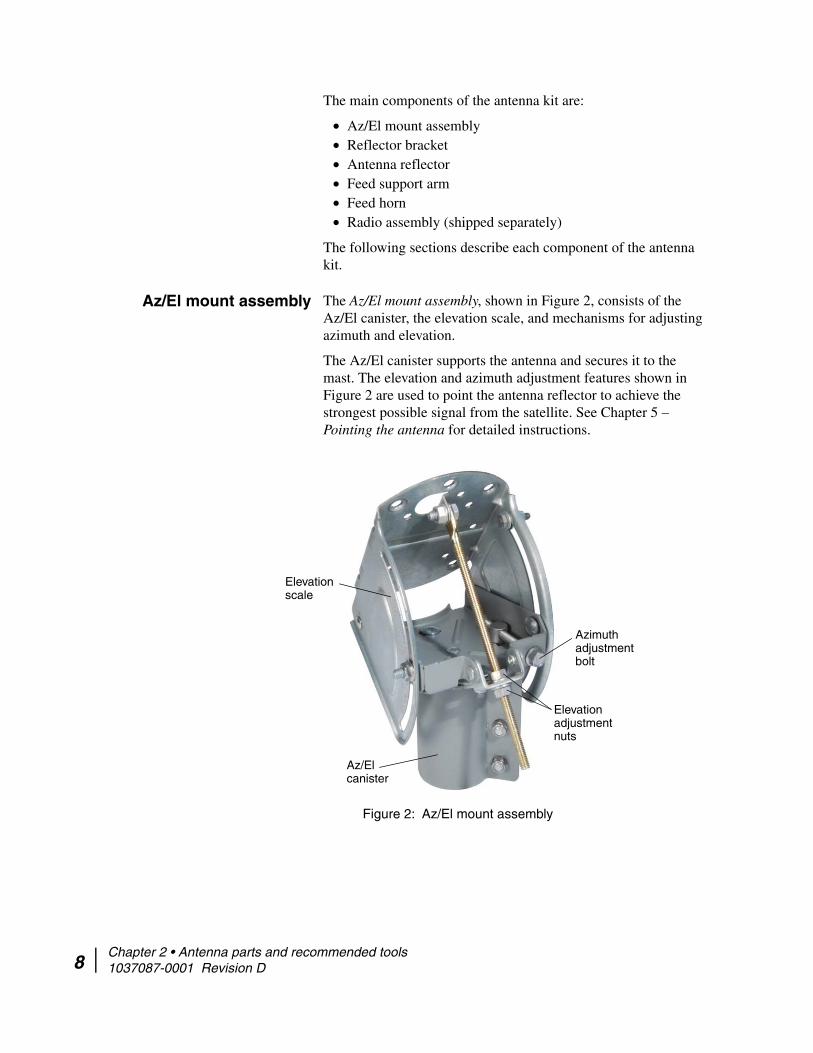
Az/El mount assembly The Az/El mount assembly, shown in Figure 2, consists of the Az/El canister, the elevation scale, and mechanisms for adjusting azimuth and elevation.
The Az/El canister supports the antenna and secures it to the mast. The elevation and azimuth adjustment features shown in Figure 2 are used to point the antenna reflector to achieve the strongest possible signal from the satellite. See Chapter 5 – Pointing the antenna for detailed instructions.
Figure 2: Az/El mount assembly
Elevation scale
Azimuth adjustment bolt
Az/El canister
Elevation adjustment nuts
Chapter 2 • Antenna parts and recommended tools 1037087-0001 Revision D

Reflector bracket and tilt plate
The reflector bracket shown in Figure 3 attaches to the Az/El mount and supports the antenna reflector. The reflector bracket and tilt plate allow the reflector to rotate so it can be adjusted for proper tilt. (See also Figure 9 on page 17.)
Figure 3: Reflector bracket and tilt plate
Reflector bracket
Tilt plate
Antenna reflector The antenna reflector shown in Figure 4, focuses both the transmitted and received RF signals. It attaches to the rest of the antenna assembly by way of the reflector bracket.
Figure 4: Antenna reflector
Handle the antenna reflector with care to avoid bending it or other damage.
NOTICE
Chapter 2 • Antenna parts and recommended tools 1037087-0001 Revision D 9

10
Feed support arm Figure 5 shows the feed support arm. The feed support arm supports the radio assembly and feed horn. It attaches to the reflector bracket.
Figure 5: Feed support arm
Radio assembly and feed horn attach to
this end.
Feed horn The feed horn, shown in Figure 6, attaches to the TRIA on the radio assembly. The feed horn gathers the reflected signal from the antenna reflector and channels it toward the LNB on the radio assembly.
Figure 6: Feed horn
Chapter 2 • Antenna parts and recommended tools 1037087-0001 Revision D
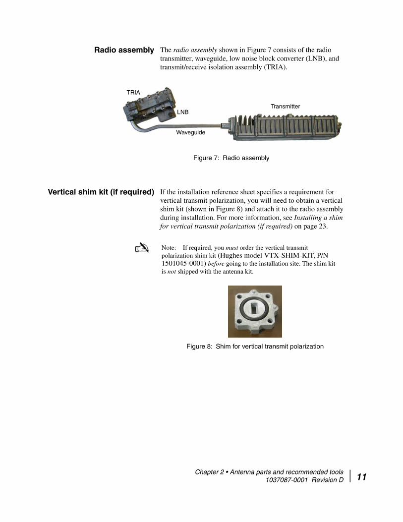
Radio assembly The radio assembly shown in Figure 7 consists of the radio transmitter, waveguide, low noise block converter (LNB), and transmit/receive isolation assembly (TRIA).
Figure 7: Radio assembly
Transmitter
TRIA
Waveguide
LNB
Vertical shim kit (if required) If the installation reference sheet specifies a requirement for vertical transmit polarization, you will need to obtain a vertical shim kit (shown in Figure 8) and attach it to the radio assembly during installation. For more information, see Installing a shim for vertical transmit polarization (if required) on page 23.
Note: If required, you must order the vertical transmit polarization shim kit (Hughes model VTX-SHIM-KIT, P/N 1501045-0001) before going to the installation site. The shim kit is not shipped with the antenna kit.
Figure 8: Shim for vertical transmit polarization
Chapter 2 • Antenna parts and recommended tools 1037087-0001 Revision D 11

12
Small hardware parts list
Table 2 lists the small hardware parts that are included with the antenna kit and radio assembly.
Table 2: Small hardware parts
Hardware in second column is used to attach . . .
Hardware parts QuantityIllustration showing
where parts are used
Reflector bracket and tilt plate to Az/El mount assembly
5/16-18 × ¾-inch carriage bolt 5 Figure 17 on page 25
5/16-inch hex flange nut 5
Antenna reflector to reflector bracket
5/16-18 × ¾-inch carriage bolt 4 Figure 11 on page 19
5/16-inch hex flange nut 4
¼ inch × ½ inch Phillips head screw 1
Feed support arm to reflector bracket
¼-20 × 1¾-inch hex bolt 2 Figure 12 on page 20
¼-inch flat washer 2
¼-inch lock washer 2
¼-inch hex nut 2
Feed horn to feed support arm ¼-20 × 1¾-inch hex bolt 1 Figure 14 on page 22
¼-inch flat washer 1
¼-inch lock washer 1
Radio assembly (transmitter) to feed support arm
5/16-20 × 1¾-inch hex bolt 2 Figure 19 on page 27
5/16-inch flat washer 2
5/16-inch lock washer 2
Radio assembly to feed horn O-ring 1 Figure 19 on page 27
M4 × 12 mm hexagonal socket head (Allen) screw
4
M4 lock washer 4
Chapter 2 • Antenna parts and recommended tools 1037087-0001 Revision D
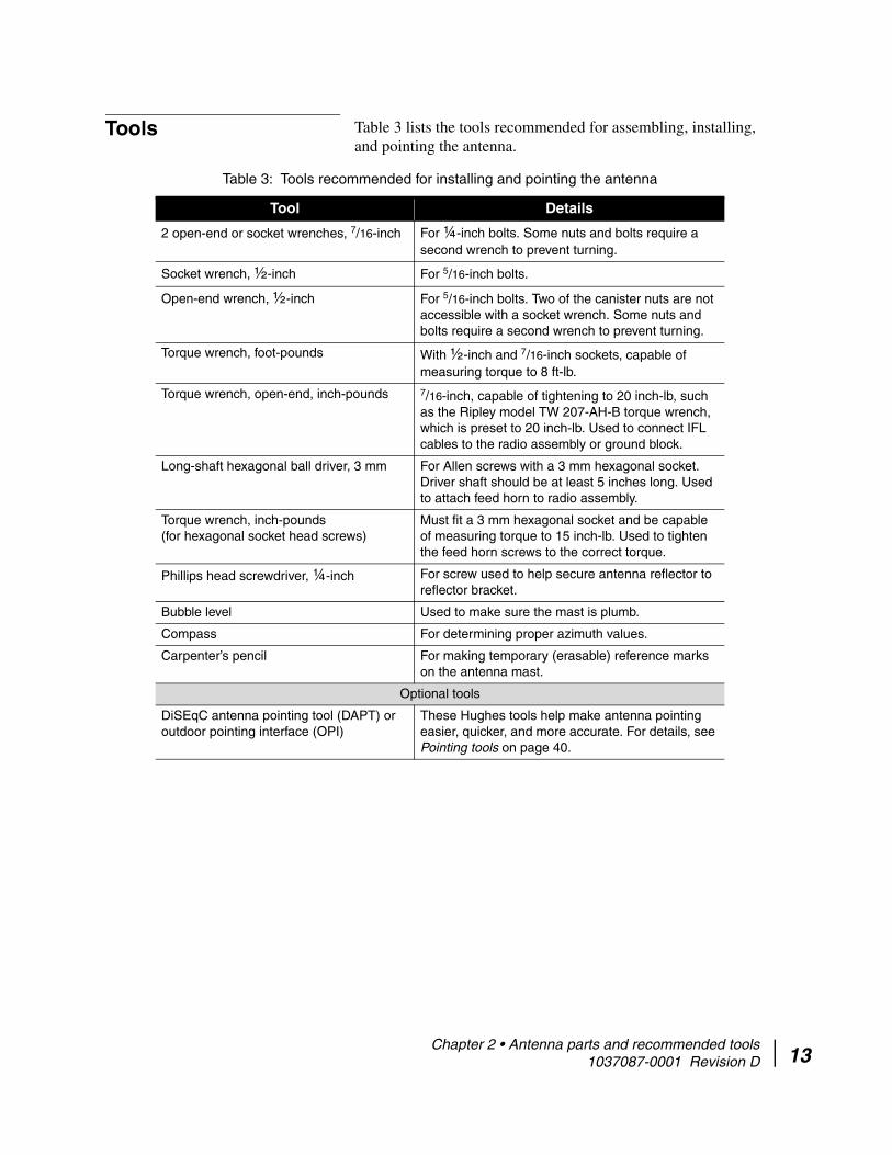
Tools Table 3 lists the tools recommended for assembling, installing, and pointing the antenna.
Table 3: Tools recommended for installing and pointing the antenna
Tool Details
2 open-end or socket wrenches, 7/16-inch For ¼-inch bolts. Some nuts and bolts require a second wrench to prevent turning.
Socket wrench, ½-inch For 5/16-inch bolts.
Open-end wrench, ½-inch For 5/16-inch bolts. Two of the canister nuts are not accessible with a socket wrench. Some nuts and bolts require a second wrench to prevent turning.
Torque wrench, foot-pounds With ½-inch and 7/16-inch sockets, capable of measuring torque to 8 ft-lb.
Torque wrench, open-end, inch-pounds 7/16-inch, capable of tightening to 20 inch-lb, such as the Ripley model TW 207-AH-B torque wrench, which is preset to 20 inch-lb. Used to connect IFL cables to the radio assembly or ground block.
Long-shaft hexagonal ball driver, 3 mm For Allen screws with a 3 mm hexagonal socket. Driver shaft should be at least 5 inches long. Used to attach feed horn to radio assembly.
Torque wrench, inch-pounds (for hexagonal socket head screws)
Must fit a 3 mm hexagonal socket and be capable of measuring torque to 15 inch-lb. Used to tighten the feed horn screws to the correct torque.
Phillips head screwdriver, ¼-inch For screw used to help secure antenna reflector to reflector bracket.
Bubble level Used to make sure the mast is plumb.
Compass For determining proper azimuth values.
Carpenter’s pencil For making temporary (erasable) reference marks on the antenna mast.
Optional tools
DiSEqC antenna pointing tool (DAPT) or outdoor pointing interface (OPI)
These Hughes tools help make antenna pointing easier, quicker, and more accurate. For details, see Pointing tools on page 40.
Chapter 2 • Antenna parts and recommended tools 1037087-0001 Revision D 13

14
Chapter 2 • Antenna parts and recommended tools 1037087-0001 Revision D
Chapter 3
Installing the antenna and radio assembly
This chapter explains how to assemble and install the antenna, radio assembly, and associated hardware. Topics in this chapter include:
• Determining the pointing values on page 15• General instructions for assembling the antenna on page 16• Installing the reflector bracket and tilt plate on page 17• Installing the antenna reflector on page 19• Installing the feed support arm on page 20• Installing the feed horn on page 21• Installing the radio assembly on page 23• Mounting the antenna assembly onto the mast pipe on
page 28
Before you install the antenna, read all safety information in Understanding safety alert messages on page xi.
Determining the pointing values
Before proceeding, install and power up the IDU so you can determine the antenna pointing values. You will need these values to point the antenna (Chapter 5).
To install the IDU and point the antenna, you use satellite-based commissioning (SBC), as explained in the IDU installation guide. SBC provides on-screen instructions that guide your through the Web-based auto-commissioning process.
The SBC software determines the initial pointing values to use for setting antenna elevation, tilt, and azimuth. (The SBC software may identify tilt as polarization.) Record these values and keep them handy for reference as you assemble and point the antenna.
CAUTION
Chapter 3 • Installing the antenna and radio assembly 1037087-0001 Revision D 15

16
General instructions for assembling the antenna
Before you assemble the antenna, read these important instructions:
• Mast – The mast (pole) must be installed before you can install the antenna. For information on antenna mast mounting methods, see the HughesNet System Antenna Site Preparation and Mount Installation Guide (1035678-0001).
Note: The outside diameter of the mast must be 2 3/ 8 inches.
• Sequence of steps – When you assemble the antenna, follow the instructions in this chapter in the order they are presented.
For rooftop installations, assemble the antenna on the ground and then carry the fully assembled antenna up to the roof.
• Tightening hardware– Do not tighten any nuts or other hardware until instructed to do so. (See also the next item, Torque.)
• Torque – To ensure successful installation of the antenna, it is critical that you tighten all nuts and socket-head screws to the torque values shown in Table 4.
Table 4: Torque specifications
Fastener or connectorProper
torque value5/16-inch bolts 8 ft-lb
¼-inch bolts 5 ft-lb
M4 hexagonal socket head screws 15 inch-lb
IFL cable connectors for connections to the radio and ground block
20 inch-lb
WARNING
Chapter 3 • Installing the antenna and radio assembly 1037087-0001 Revision D

Installing the reflector bracket and tilt plate
Attach the tilt plate and reflector bracket to the Az/El mount as shown in Figure 9.
1. Position the Az/El mount so the flat part with five holes faces upward.
2. Place the reflector bracket against the Az/El mount.See Figures 9 and 10.
3. Place the tilt plate over the round opening in the reflector bracket.
4. Rotate the tilt plate so that each of the five holes in the Az/El mount is aligned with a hole in the tilt plate. (There are extra holes in the tilt plate that will not line up with holes in the Az/El mount.)
Figure 9: Attaching the reflector bracket and tilt plate
Make sure the tilt scale faces the Az/El mount.
Tilt plate
Az/El mount
Reflector bracket
5 bolts
Tilt scale
Align pointer ( ^ ) with zero on tilt scale.
(Some holes are not used.)
5. Insert five carriage bolts through the tilt plate and into the holes in the Az/El mount.
6. From the opposite side of the reflector bracket, place a hex flange nut on each bolt and tighten the nuts lightly, only until snug.
Chapter 3 • Installing the antenna and radio assembly 1037087-0001 Revision D 17

18
The reflector bracket should rotate freely between the Az/El mount and the tilt plate.When the reflector bracket is correctly attached to the Az/El mount, you can see the tilt scale numbers above the tilt pointer, as shown in Figure 10.
Figure 10: Tilt pointer aligned with zero on tilt scale
Tilt scale In this example, tilt = 0 ° Tilt pointer
7. Using the tilt value you obtained from the IDU as described in Determining the pointing values, set the pointer so it points to the correct tilt angle on the tilt scale
8. Lock down the five flange nuts. (These five nuts are the tilt lockdown nuts.)
Chapter 3 • Installing the antenna and radio assembly 1037087-0001 Revision D
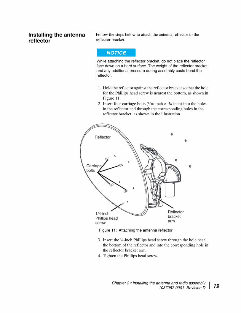
Installing the antenna reflector
Follow the steps below to attach the antenna reflector to the reflector bracket.
While attaching the reflector bracket, do not place the reflector face down on a hard surface. The weight of the reflector bracket and any additional pressure during assembly could bend the reflector.
1. Hold the reflector against the reflector bracket so that the hole for the Phillips head screw is nearest the bottom, as shown in Figure 11.
2. Insert four carriage bolts (5/16-inch × ¾-inch) into the holes in the reflector and through the corresponding holes in the reflector bracket, as shown in the illustration.
Figure 11: Attaching the antenna reflector
3. Insert the ¼-inch Phillips head screw through the hole near the bottom of the reflector and into the corresponding hole in the reflector bracket arm.
4. Tighten the Phillips head screw.
NOTICE
Chapter 3 • Installing the antenna and radio assembly 1037087-0001 Revision D 19

20
5. From the back of the reflector bracket, secure the four carriage bolts with four ½-inch hex flange nuts and tighten the nuts.
Note: Make sure the carriage bolts are firmly seated before tightening the nuts.
Installing the feed support arm
To install the feed support arm:
1. Insert the feed support arm into the housing at the bottom of the reflector bracket, as shown in Figure 12.
Figure 12: Attaching the feed support arm to the tailpiece
Feed support arm
Feed support arm, installed
2. As shown in the figure, insert two ¼-inch × 1¾-inch bolts down through the reflector bracket housing into the feed support arm.
3. Place one flat washer, lock washer, and hex nut onto each bolt and tighten.
Chapter 3 • Installing the antenna and radio assembly 1037087-0001 Revision D

Installing the feed horn To attach the feed horn to the radio assembly:
1. Remove and discard the white protective seal from the end of the feed horn. Be sure not to remove or damage the clear cellophane cover underneath the white seal.
Do not remove the transparent moisture seal on the small end of the feed horn. However, if the seal is damaged, wrinkled, or loose, remove it.
2. Insert the O-ring into the groove inside the stem as shown in Figure 13.
Figure 13: Inserting the O-ring into the feed horn
NOTICE
Chapter 3 • Installing the antenna and radio assembly 1037087-0001 Revision D 21

22
3. Position the feed horn near the end of the feed support arm as shown in Figure 14.
Figure 14: Installing the feed horn
Feed horn bolt
Feed horn installed on support arm
Feed horn
PegBolt
Close-up view
Peg hole
As shown in the figure, there is a peg on the bottom of the feed horn. This peg fits into the small hole closest to the end of the feed support arm. The second hole (nearer to the antenna reflector) is for the bolt that secures the feed horn to the feed support arm.
4. Insert the ¼-inch × 1¾-inch bolt, with ¼-inch flat washer and lock washer, upward through the feed support arm and into the feed horn.
5. Tighten the bolt.
Chapter 3 • Installing the antenna and radio assembly 1037087-0001 Revision D

Installing the radio assembly
The radio assembly is shipped from the factory with a horizontal transmit polarization shim installed. If the installation requires vertical transmit polarization, you must remove the horizontal shim and replace it with a vertical shim before you install the radio assembly.
Before proceeding, check the installation reference sheet to determine whether the installation calls for horizontal or vertical polarization.
Installing a shim for vertical transmit polarization
(if required)
Follow the instructions in this section only if the installation reference sheet states that vertical transmit polarization is required. If vertical transmit polarization is not required, skip this section and go to Installing the radio assembly on page 26.
Figure 15 shows the location of the shim and shows three of the four Allen screws that hold the shim in place.
Figure 15: Shim location next to TRIA
TRIA
Shim (See also Figure 16.)
Allen screws (4 total)
Waveguide
To replace the horizontal shim with a vertical shim:
Note: For this procedure, you need a vertical transmit polarization shim kit (Hughes model VTX-SHIM-KIT, P/N 1501045-0001) as explained in Vertical shim kit (if required) on page 11. Figure 16 on page 24 shows what a vertical shim kit looks like.
1. Loosen and remove the four Allen screws that hold the horizontal shim in place. See Figure 15.
2. Carefully separate the end of the waveguide from the shim.
Chapter 3 • Installing the antenna and radio assembly 1037087-0001 Revision D 23

24
Figure 16 illustrates the visible difference between a horizontal shim and a vertical shim. Note the positions of the alignment pins in the two photos.
Figure 16: Horizontal shim and vertical shim for transmit polarization
TRIA
Horizontal shim in place Vertical shim in place
(In this photograph, the TRIA has not yet been rotated.)
Alignment pins
O-ring
Horizontal shim Vertical shim
Alignment pins
3. Remove the horizontal shim and O-ring.4. Install the vertical shim with O-ring in the same location.
Because of its shape and the location of the alignment pins on the TRIA, the vertical shim can only be installed in the position shown in the upper right photo of Figure 16. Note the position of the shim alignment pins in the photo.
5. Rotate the TRIA 90 ° from its horizontal polarization position as shown in Figure 17. You must rotate the TRIA before you re-attach the waveguide so the waveguide end plate will fit onto the shim alignment pins. See Figures 17 and 18.
Chapter 3 • Installing the antenna and radio assembly 1037087-0001 Revision D

Figure 17: Direction of TRIA rotation for vertical polarization
For comparison, Figure 18 shows the appearance of the TRIA when positioned for horizontal transmit polarization and for vertical transmit polarization.
Figure 18: TRIA position for horizontal and vertical transmit polarization
Horizontal polarization
TRIA rotated for vertical polarization
TRIA
TRIA
Chapter 3 • Installing the antenna and radio assembly 1037087-0001 Revision D 25

26
6. Be sure the O-ring is in place in the shim.7. Place the waveguide end plate against the shim.8. Insert and tighten the four Allen screws.
Make sure the O-ring remains in the groove in the shim. If the O-ring is not positioned properly, moisture will accumulate inside the TRIA and cause damage to the radio.
Installing the radio assembly
After determining the required polarization setting and ensuring that the proper polarization shim is in place, you can install the radio assembly.
Note: Before installing the radio, you must first determine the necessary polarization setting and, if necessary, install a vertical polarization shim as described in Installing a shim for vertical transmit polarization (if required) on page 23.
To install the radio assembly:
1. Position the radio assembly below the feed support arm as shown in Figure 19.
NOTICE
Chapter 3 • Installing the antenna and radio assembly 1037087-0001 Revision D

Figure 19: Installing the radio assembly
Installed radio assembly
O-ring
Radio assembly
Bolts
2. Insert two 5/16-inch × 1¾-inch bolts, with 5/16-inch flat washers and lock washers, downward through the feed support arm and into the transmitter. Do not fully tighten the bolts at this time.
3. Separate the rear end of the feed horn from the radio assembly and insert the O-ring into the groove inside the feed horn stem as shown in Figure 19.
Chapter 3 • Installing the antenna and radio assembly 1037087-0001 Revision D 27
28
4. Attach the radio assembly to the feed horn using the provided M4 × 12-mm socket-head screws with M4 lock washers.
You must make sure that the O-ring remains in the groove at the end of the feed horn before attaching the radio. If the O-ring is not positioned properly, moisture will accumulate inside the TRIA, causing damage to the radio.
5. Use a long-shaft ball driver 3 mm Allen wrench to tighten the socket-head screws.
6. When the radio assembly is fully assembled, tighten the two bolts to secure the transmitter to the feed support arm.
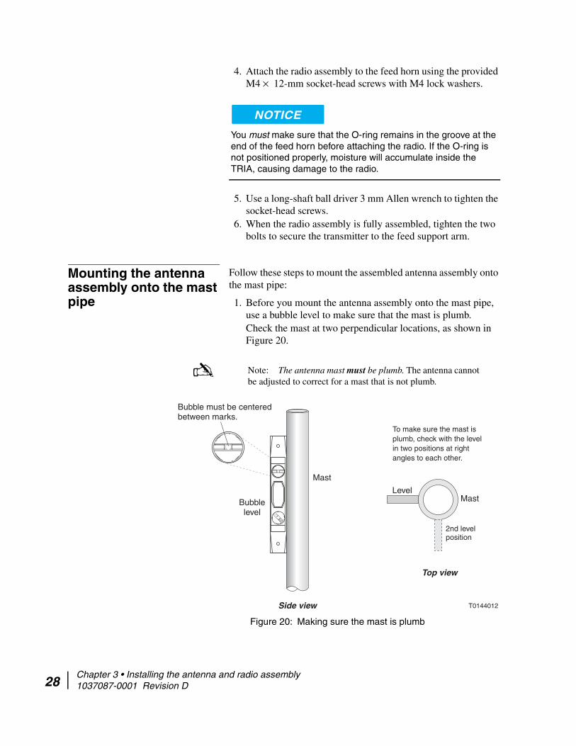
Mounting the antenna assembly onto the mast pipe
Follow these steps to mount the assembled antenna assembly onto the mast pipe:
1. Before you mount the antenna assembly onto the mast pipe, use a bubble level to make sure that the mast is plumb. Check the mast at two perpendicular locations, as shown in Figure 20.
Note: The antenna mast must be plumb. The antenna cannot be adjusted to correct for a mast that is not plumb.
Figure 20: Making sure the mast is plumb
T0144012
Top view
To make sure the mast isplumb, check with the levelin two positions at rightangles to each other.
LevelMast
2nd levelposition
Mast
Bubble must be centeredbetween marks.
Bubblelevel
Side view
NOTICE
Chapter 3 • Installing the antenna and radio assembly 1037087-0001 Revision D

2. Slide the Az/El mount assembly canister down onto the mast as shown in Figure 21.
Note: The outside diameter of the mast must be 23/ 8 inches.
Figure 21: Installing the Az/El mount assembly
Az/El mount assembly
Not shown: Antenna reflector
and reflector bracket
Az/El canister
Mast
3. Fully tighten any hardware that is not tight—however, leave nuts and flanges that are used for pointing adjustments either loose or just snug. All such hardware is pointed out in Chapter 5 – Pointing the antenna.
Chapter 3 • Installing the antenna and radio assembly 1037087-0001 Revision D 29

30
This completes assembly of the antenna. Depending on its orientation, the antenna should look similar to the one shown in Figure 22.
Figure 22: Assembled antenna
Next you must route and connect the IFL transmit and receive cables between the antenna and the IDU, as explained in Chapter 4 – Cabling and connections.
Chapter 3 • Installing the antenna and radio assembly 1037087-0001 Revision D

Chapter 4
Cabling and connectionsThis chapter illustrates where the antenna transmit and receive connectors are located; describes how to route the transmit and receive cables at the antenna; and explains how to connect the transmit and receive cables to the radio assembly. You must connect each of these cables before pointing the antenna at the HughesNet system satellite (as described in Chapter 5).
Topics in this chapter include:
• Cabling requirements on page 31• Routing the IFL cables at the antenna on page 32• Connecting the transmit and receive cables on page 34• Ground connection on page 35
Cabling requirements For a list of approved coaxial cable types for the IFL between the antenna and the IDU, see the Hughes FSB, IFL Cable, Approved List (with lengths) for DW7x00, DW60xx, and DW40xx Domestic Installations (FSB_060316_01). This FSB lists the maximum cable length for each approved cable type for all relevant radio types.
Because each installation site has unique requirements, you must use your own judgment and best practices to determine how to safely route the IFL cables.
Coaxial cables and connectors can corrode if exposed to moisture. Use only compression type connectors, and weatherproof them with dielectric grease and weatherproofing tape.
Note: For connector and ground block requirements, see the Hughes FSB, HNS Broadband Requirements for RG-6 and RG-11 IFL Cable Connectors, Ground Blocks and Ground Block Location (FSB 50518_01).
NOTICE
Chapter 4 • Cabling and connections 1037087-0001 Revision D 31
32
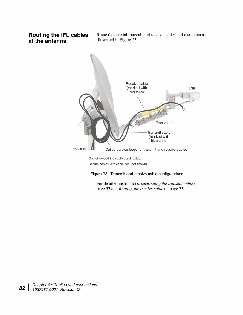
Routing the IFL cables at the antenna
Route the coaxial transmit and receive cables at the antenna as illustrated in Figure 23.
Figure 23: Transmit and receive cable configurations
T0144013
Transmitter
Transmit cable(marked with
blue tape)
Receive cable(marked with
red tape)LNB
Do not exceed the cable bend radius.
Secure cables with cable ties (not shown).
Coiled service loops for transmit and receive cables
For detailed instructions, seeRouting the transmit cable on page 33 and Routing the receive cable on page 33.
Chapter 4 • Cabling and connections 1037087-0001 Revision D
Routing the transmit cable 1. Route the transmit cable (marked with blue electrical tape) over the Az/El mount assembly, down behind the reflector, and along the feed support arm to the rear of the transmitter, in a configuration similar to that shown in Figure 23.
2. Leave a 10 ft coiled service loop and secure it either to the mast, Az/El mount assembly, or reflector bracket.
Note: Do not leave the service loop lying on the roof or other mounting surface. Do not block access to the azimuth and elevation adjustment features on the Az/El mount assembly.
3. Coil any extra cable, and secure the transmit cable with cable ties.
Where IFL cables connect to the radio or to a ground block, tighten the cable connector to the torque specified in Table 4 on page 16. Overtightening the radio connectors can result in damage to the radio assembly.
Routing the receive cable 1. Route the receive cable (marked with red electrical tape) over the Az/El mount assembly, down behind the reflector, and along the feed support arm to the LNB, in a configuration similar to that shown in Figure 23 on page 32.
2. Leave a 10 ft coiled service loop and secure it to either the mast, Az/El mount assembly, or reflector bracket.
3. Coil any extra cable, and secure the receive cable with cable ties.
NOTICE
Chapter 4 • Cabling and connections 1037087-0001 Revision D 33

34
Connecting the transmit and receive cables
This section explains how to connect the transmit and receive cables to the radio assembly at the antenna.
Because the antenna pointing procedure requires that you disconnect the receive cable, wait until pointing is complete before taping the outdoor connections.
Connecting the transmit cable
Connect the transmit cable to the radio transmitter as follows:
1. Make sure the IDU is powered off.2. Apply a small amount of dielectric grease to the inside of the
transmit cable connector (marked with blue electrical tape).3. Connect the transmit cable to the transmitter connector
marked IFL, shown in Figure 24.
Figure 24: Transmit connector
4. Tighten the cable connector.5. Secure the cable with cable ties.
Connecting the receive cable
Connect the receive cable to the LNB as follows:
Note: If you are going to use an electronic pointing tool to point the antenna, you can connect the receive cable now (steps 1 through 6 in this section) and later disconnect the LNB end to connect the pointing tool as explained in Pointing tools on page 40. Or, you may prefer to connect the pointing tool now (as you connect the receive cable). If you connect the pointing tool now, step 3 below does not apply.
NOTICE
Chapter 4 • Cabling and connections 1037087-0001 Revision D

1. Make sure the IDU is powered off.2. Apply a small amount of dielectric grease to the inside of the
receive cable connector (marked with red electrical tape).3. Connect the receive cable to the receive connector on the
LNB, shown in Figure 25.
Figure 25: Receive connector
4. Tighten the cable connector.5. Secure the cable with cable ties.6. After the transmit and receive cables are connected to the
radio and the IDU, reapply power to the IDU as instructed in the IDU installation guide.
Ground connection Ground the antenna as instructed in the documents listed in Grounding on page 5. Use of the ground screw on the radio assembly is optional. The radio is grounded through the shield in the coaxial cable and the ground block.
Chapter 4 • Cabling and connections 1037087-0001 Revision D 35

36
Chapter 4 • Cabling and connections 1037087-0001 Revision D
Chapter 5
Pointing the antenna This chapter explains the antenna pointing procedure. Pointing is a critical part of the HughesNet antenna installation process. If the antenna is not properly pointed toward the HughesNet system satellite, the IDU cannot communicate with the satellite to its full capacity, resulting in a degradation of system performance.
Topics in this chapter include:
• Antenna pointing overview on page 39• Prerequisites for antenna pointing on page 40• Pointing tools on page 40• Adjusting the antenna on page 44• Setting coarse elevation on page 45• Receive pointing on page 47• Isolating the transmit signal on page 53• Final steps on page 56
Chapter 5 • Pointing the antenna 1037087-0001 Revision D 37

38
Antenna pointing safety precautions
While pointing the antenna, observe the following safety precautions:
Observe these precautions to avoid exposure to RF radiation, a potential safety hazard:
• This device emits radio frequency energy when in transmit mode. To avoid injury, do not place head or other body parts between feed horn and antenna when system is operational. Keep at least 3 ft away from the area between the feed horn and the reflector when the system is operational.
• Make sure the cylindrical space projecting outward from the antenna reflector toward the satellite does not intersect or come close to any inhabited areas.
• Disconnect power from the IDU before performing maintenance or adding upgrades to any antenna components.
Failure to observe these cautions could result in injury to the eyes or other personal injury.
Do not try to make antenna pointing adjustments by pulling on the antenna reflector or feed support arm. Doing so could cause permanent damage to the antenna. Instead use the adjustment mechanisms and procedures described in this chapter.
CAUTION
NOTICE
Chapter 5 • Pointing the antenna 1037087-0001 Revision D

Antenna pointing overview
Correct antenna alignment is critical to the operation of the system. When the antenna is pointed directly at the satellite, it receives a strong signal. If it is not pointed properly, the signal may be weak, causing errors to occur during data transfers.
Antenna pointing is accomplished by first receive pointing the antenna and then isolating the transmit signal. Receive pointing adjusts the antenna to obtain the best receive signal. Isolating the transmit signal fine-tunes the antenna alignment for the strongest possible signal received by the HN System NOC. Both of these processes are explained later in this chapter.
The pointing process requires that you make a number of small position adjustments to the antenna until you are satisfied that you have obtained the strongest possible signal. When you have achieved the strongest possible signal, you have peaked the signal.
This chapter describes a general procedure for pointing the antenna. The objectives of antenna pointing are to:
• Locate and detect the satellite signal• Peak the signal to achieve the greatest possible signal
strength
Using the SBC software The SBC software guides you through a step-by-step process for commissioning the IDU and pointing the antenna. It determines your location and calculates the values you use to set antenna elevation, tilt angle, and azimuth.
Use the information in this chapter as a guide for the overall pointing process and for instructions on how to make mechanical adjustments to the antenna. For specific steps, follow the instructions in the IDU installation guide and on the SBC software screens.
In general, you will alternate between two activities. These are:
• Following the software prompts and instructions• Adjusting the antenna (elevation, tilt angle, and azimuth) to
acquire and then peak the satellite signal. The required adjustments are different for each installation location.
Peaking the signal Peaking is the term used to describe the process of achieving the highest possible signal strength available from the satellite. You may find that you achieve the strongest signal strength after just a few adjustments, or you may find that several adjustments are needed. By obtaining the strongest possible signal, you ensure that the IDU can operate at the optimum performance level.
Chapter 5 • Pointing the antenna 1037087-0001 Revision D 39

40
Prerequisites for antenna pointing
The following are required for antenna pointing:
• The antenna must be installed.• The IDU must be installed.• The IFL transmit and receive cables must be connected to
both IDU and the antenna.• Both the antenna and the IDU must be grounded.• If used, the pointing tool (DAPT or OPI) must be installed.
(See Installing the DAPT on page 41 or Installing the OPI on page 43.)
Pointing tools Hughes has developed two tools that make antenna pointing easier, faster, and more accurate. Both tools are optional; however, Hughes highly recommends that you use one of them for easier and more accurate antenna pointing. The pointing tools are:
• DiSEqC antenna pointing tool (DAPT)• Outdoor pointing interface (OPI)
Both devices display values that indicate signal strength during antenna pointing, eliminating the need for a laptop computer at the antenna installation site.
DAPT The DAPT, Hughes P/N 1501471-0002, is a digital satellite equipment control (DiSEqC) tool. It has two connectors, a large back-lit display, and three buttons, as shown in Figure 26. For Ku-band antenna pointing, only the Advance button (button 3) is used.
Figure 26: DiSEqC Antenna Pointing Tool (DAPT)
Cable connector
Display
Advance button
Chapter 5 • Pointing the antenna 1037087-0001 Revision D
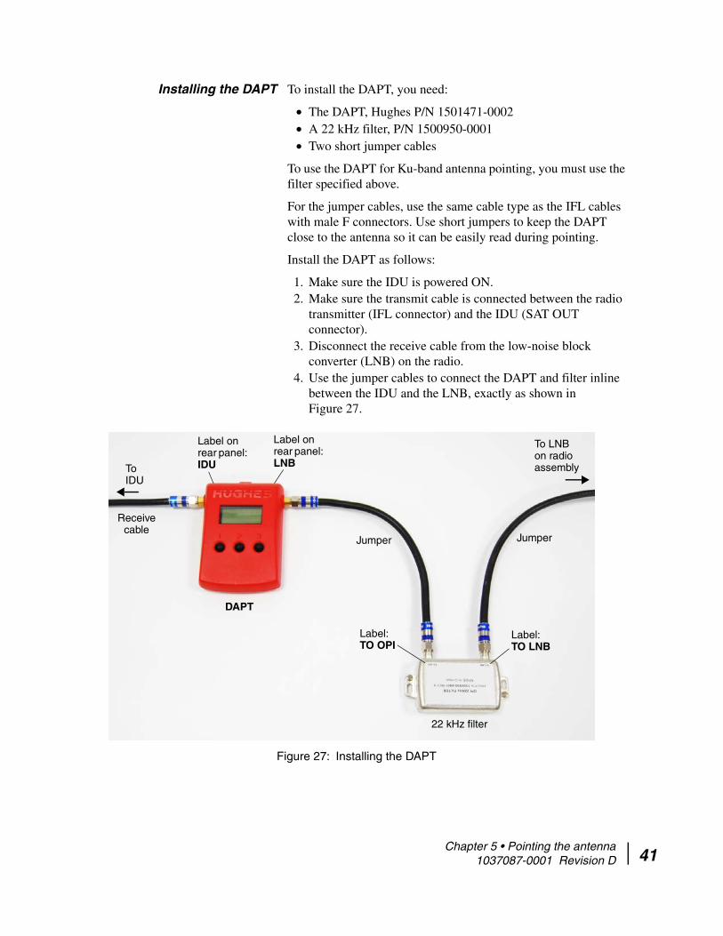
Installing the DAPT To install the DAPT, you need:
• The DAPT, Hughes P/N 1501471-0002• A 22 kHz filter, P/N 1500950-0001• Two short jumper cables
To use the DAPT for Ku-band antenna pointing, you must use the filter specified above.
For the jumper cables, use the same cable type as the IFL cables with male F connectors. Use short jumpers to keep the DAPT close to the antenna so it can be easily read during pointing.
Install the DAPT as follows:
1. Make sure the IDU is powered ON.2. Make sure the transmit cable is connected between the radio
transmitter (IFL connector) and the IDU (SAT OUT connector).
3. Disconnect the receive cable from the low-noise block converter (LNB) on the radio.
4. Use the jumper cables to connect the DAPT and filter inline between the IDU and the LNB, exactly as shown in Figure 27.
Figure 27: Installing the DAPT
DAPT
To IDU
To LNB on radio assembly
22 kHz filter
Label on rear panel: IDU
Label on rear panel: LNB
Label: TO OPI
Label: TO LNB
Receive cable
Jumper Jumper
Chapter 5 • Pointing the antenna 1037087-0001 Revision D 41

42
Understanding the DAPT display
When connected properly, the DAPT initially displays the IFL receive cable voltage on its LCD display, as shown in this example (the actual voltage may vary):
Important: To see pointing values, as described below, you must check the box labeled Enable OPI Display on the appropriate SBC screen on the installer laptop computer.
If the IDU is in receive pointing mode and you press the Advance button (3), the display changes from IFL cable voltage to COMM Startup and then (automatically) to Mode and Value:
The mode is either 0 or 2:
• 0 – Receive pointing.• 2 – Automatic cross-pol (ACP), manual or automatic:
– Manual – The value is dynamic; it changes constantly.– Automatic – The value is static; it does not change.
You cannot change the mode from the DAPT; you can only change modes through the laptop connected to the IDU.
In all modes the value is a relative indication of signal strength. A higher number indicates a stronger signal.
OPI The OPI, P/N 1031393-0002 (Figure 28) is a portable repeater that displays signal strength values during antenna pointing.
Figure 28: Outdoor Pointing Interface (OPI)
Cable connector
Display
Chapter 5 • Pointing the antenna 1037087-0001 Revision D

Installing the OPI To install the OPI, you need:
• The OPI, Hughes P/N 1031393-0002• A 22 kHz filter, P/N 1500950-0001.• Two short jumper cables
To use the OPI for Ku-band antenna pointing, you must use the specified filter. For the jumper cables, use the same cable type as the IFL cables with male F connectors. Use short jumpers so you can read the OPI close to the antenna during pointing.
Install the OPI as follows:
1. Make sure the IDU is powered ON.2. Make sure the transmit cable is connected between the radio
transmitter and the IDU (SAT OUT connector).3. Disconnect the receive cable from the LNB on the radio.4. Use the jumper cables to connect the OPI and filter inline
between the IDU and LNB, exactly as shown in Figure 29.
Figure 29: Installing the OPI
OPI
To IDU To LNB on radio assembly
22 kHz filter
Label: TO OPI
Label: TO LNB
Receive cable
JumperJumper
Important: The OPI will not work unless it is enabled on the appropriate SBC screen. (Check the box labeled Enable OPI Display.) For further details, see Outdoor Pointing Interface Operating Instructions (1031832-0001).
Chapter 5 • Pointing the antenna 1037087-0001 Revision D 43

44
Adjusting the antenna To point the antenna, you must make three adjustments to the position of the antenna reflector:
• Elevation – Adjustment up and down• Tilt angle – Rotational adjustment• Azimuth – Side-to-side adjustment
These adjustments are illustrated in Figure 30.
Figure 30: Adjusting azimuth, elevation, and tilt
Chapter 5 • Pointing the antenna 1037087-0001 Revision D

Setting coarse elevation To set the antenna elevation to the value provided by the SBC software:
1. Loosen the elevation lockdown nuts on each side of the Az/El mount assembly. (See Figure 31.)
Figure 31: Elevation adjustment rod, adjustment and lockdown nuts, and scale
Elevation scale
Elevation adjustment rod
Elevation lockdown nut
(1 on each side)
Elevation adjustment nuts
2. Tilt the reflector either forward or backward to set the elevation to the value given by the SBC software.
Do not try to make antenna pointing adjustments by pulling on the antenna reflector or feed support arm. Doing so could cause permanent damage to the antenna. Instead use the adjustment mechanisms and procedures described in this chapter.
NOTICE
Chapter 5 • Pointing the antenna 1037087-0001 Revision D 45

46
Fine elevation adjustment To fine-tune the elevation setting:
1. Make sure the two elevation lockdown nuts are loose enough to allow the reflector to move up and down smoothly on a vertical axis.
2. Loosen the top elevation adjustment nut and spin it counter-clockwise until it is an inch or two up the elevation adjustment rod.
3. While watching the signal strength display, use the lower elevation adjustment nut to adjust the elevation until you achieve the maximum signal strength. As shown in Figure 32, the black line on the bar behind the lockdown nut acts as a pointer to indicate the value in the elevation scale. For example, the antenna shown in the figure is adjusted to 26°.
Figure 32: Elevation marker
Arrow points to the elevation marker (below bolt).
4. When the signal is peaked, spin the top elevation adjustment nut clockwise until it is snug against the base plate.
5. Lock down the elevation by tightening the two lockdown nuts on either side of the Az/El mount.
Chapter 5 • Pointing the antenna 1037087-0001 Revision D

Receive pointing Receive pointing peaks the receive signal. You must peak the signal even if the antenna is locked to it.
Use the SBC software or one of the two pointing tools (DAPT or OPI) to check the signal strength, then adjust the antenna to peak the signal. Detailed instructions for these procedures are given in the following sections.
Initial elevation setting Make sure the antenna is set to the initial elevation value given by the SBC software. Coarse elevation should already be set as outlined in Setting coarse elevation on page 45.
Setting the tilt angle Tilt angle refers to the rotation of the antenna reflector (as shown in Figure 30 on page 44) and is measured in degrees from zero (no rotation), either positive or negative. The tilt angle is positive when east of the satellite longitude and negative when west of the satellite longitude.
To set the antenna tilt to the initial value provided by the SBC software:
1. Loosen the five tilt lockdown nuts that secure the reflector bracket to the Az/El mount just enough so you can rotate the antenna reflector on the reflector bracket. Figure 33 shows the location of the flange nuts.
Figure 33: Location of tilt lockdown nuts
Arrows point to flange nut locations.
One of the flange nut locations is not visible in this view.
(The flange nuts are not shown in this photo.)
Chapter 5 • Pointing the antenna 1037087-0001 Revision D 47

48
2. Rotate the reflector bracket until the tilt pointer aligns with the tilt value you obtained from the SBC software (as explained in Determining the pointing values on page 15). (See Figure 34.)
Figure 34: Tilt scale
Tilt scale In this example, tilt = 0 ° Tilt pointer
3. Lock down the hex flange nuts.
Chapter 5 • Pointing the antenna 1037087-0001 Revision D
Setting azimuth Follow the instructions in this section to set the antenna azimuth position so you can detect the receive signal and then obtain the highest signal strength.
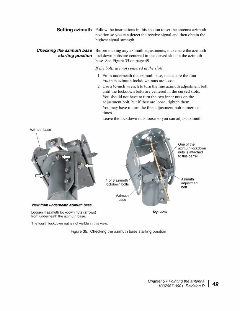
Checking the azimuth base starting position
Before making any azimuth adjustments, make sure the azimuth lockdown bolts are centered in the curved slots in the azimuth base. See Figure 35 on page 49.
If the bolts are not centered in the slots:
1. From underneath the azimuth base, make sure the four 5/16-inch azimuth lockdown nuts are loose.
2. Use a ½-inch wrench to turn the fine azimuth adjustment bolt until the lockdown bolts are centered in the curved slots.You should not have to turn the two inner nuts on the adjustment bolt, but if they are loose, tighten them.You may have to turn the fine adjustment bolt numerous times.Leave the lockdown nuts loose so you can adjust azimuth.
Figure 35: Checking the azimuth base starting position
The fourth lockdown nut is not visible in this view.
One of the azimuth lockdown nuts is attached to this barrel.
Azimuth adjustment bolt
Top view
Azimuth base
1 of 3 azimuth lockdown bolts
Azimuth base
Loosen 4 azimuth lockdown nuts (arrows) from underneath the azimuth base.
View from underneath azimuth base
Chapter 5 • Pointing the antenna 1037087-0001 Revision D 49

50
Coarse azimuth adjustment For coarse azimuth adjustment, loosen the Az/El canister nuts shown in Figure 36:
1. Loosen the three Az/El canister nuts enough to allow the antenna assembly to rotate freely on the mast.
Figure 36: Az/El canister nuts
2. Use a compass to determine the azimuth direction specified by the SBC software.
3. Holding the antenna assembly by the reflector bracket, point the antenna reflector as accurately as possible toward the specified azimuth direction.
Chapter 5 • Pointing the antenna 1037087-0001 Revision D
Fine azimuth adjustment For fine azimuth adjustment, use the azimuth adjustment bolt shown in Figure 35 on page 49:
1. Make sure the Az/El canister nuts are tight enough to prevent the antenna from rotating on the mast.
2. Using a ½-inch wrench, rotate the azimuth adjustment bolt shown in Figure 35 on page 49, to adjust the azimuth to the right about 1/ 8 inch.
3. Wait 5 full seconds while reading the signal strength value from the DAPT, OPI, or computer. You must allow the IDU enough time to track and register the signal strength.
Note: Make small azimuth adjustments (no more than 1/ 8 inch as measured at the mast). Allow 5 sec between each adjustment to give the IDU enough time to lock onto the satellite signal.
4. After acquiring a signal, rotate the azimuth adjustment bolt in either direction to achieve the desired azimuth angle.
Note: Azimuth measurements are calibrated relative to true north, not magnetic north.
5. Continue adjusting the azimuth as necessary to obtain the highest signal strength. If you do not detect a signal, refer to the instructions in If no signal is present below.
6. When the signal strength is at its highest, tighten the azimuth lockdown nuts.
7. Proceed to Peaking the receive signal on page 52 and follow the instructions there.
If no signal is present If, after following the preceding instructions for coarse and fine azimuth adjustment, you do not detect a signal, follow these steps:
1. Point the antenna reflector as accurately as possible toward the specified azimuth direction.
2. Repeat steps 2 through 4 in Fine azimuth adjustment. 3. Continue moving the antenna reflector to the right in 1/ 8-inch
increments until you detect a signal.4. If there is no signal, sweep back 1/ 8 inch at a time to the left
until you detect a signal.
If you still cannot detect a signal, contact Installer Support.
Chapter 5 • Pointing the antenna 1037087-0001 Revision D 51

52
Peaking the receive signal Peaking refers to antenna adjustments you make to achieve the highest possible signal strength available from the satellite. Peak the receive signal as follows:
Note: To adjust elevation, azimuth, or tilt, you must first loosen the elevation, tilt, or azimuth lockdown nuts unless they are already loose.
For all instructions to lock down adjustment nuts or bolts, tighten the nuts to the torque values given in Table 4 on page 16.
1. Mark the current azimuth bearing on the mast with a pencil so you can find it again later.
2. Loosen the azimuth lockdown nuts (Figure 35 on page 49) just enough so you can rotate the antenna reflector slightly.
3. Holding the antenna assembly by the reflector bracket, rotate the reflector a few degrees in the same direction as when you first received the satellite signal.
4. Pause for 5 sec, check the reading, and continue turning the reflector in this fashion until the signal strength value begins to decrease.
5. When the numbers begin to decrease, slowly turn the reflector in the opposite direction until you regain the highest number that was previously achieved.
6. When you have peaked the signal by adjusting the azimuth position, lock down the four nuts under the azimuth base and fully tighten the three Az/El canister nuts.
7. Erase all pencil marks previously made on the mast.8. Adjust the elevation and tilt as necessary to obtain the highest
quality signal.9. Lock down all antenna adjustment bolts (elevation, tilt, and
azimuth).
NOTICE
Chapter 5 • Pointing the antenna 1037087-0001 Revision D

Isolating the transmit signal
To prevent any overlap between the transmit and receive signals, you must use a procedure known as Automated Cross-Polarization (ACP) to isolate the transmit signal from the receive signal. ACP test functions are included in the SBC software.
The ACP test software operates in two modes—manual and automatic. Manual mode provides real-time feedback of cross-polarization isolation measurements while you adjust the antenna. Automatic mode takes a snapshot of the current cross-polarization isolation measurement.
ACP fine pointing is a method of testing the antenna position using both the manual and automatic modes, and adjusting the antenna in small increments (if necessary) until it passes both the manual and automatic ACP tests.
The instructions provided in the following sections are general instructions only. The SBC software screens will initiate the tests and walk you through the actual procedures.
Manual ACP test All antenna adjustment bolts must be locked down before you perform ACP tests. The adjustments should already be locked down as the last step in Peaking the receive signal on page 52.
To run a manual ACP test:
1. Initiate the manual SBC software ACP test.2. Select the Manual cross polarization test.
If the manual ACP test passes, stop the test and proceed to Automatic ACP test on page 55.
If the manual ACP test fails, let the test continue and follow these steps:
Adjust tilt slightly:
1. Loosen the tilt lockdown nuts (Figure 33 on page 47) just enough so you can rotate the antenna reflector slightly.
2. Rotate the antenna slightly until you achieve the maximum isolation value.
3. While monitoring to make sure the isolation stays at the maximum value, tighten the tilt lockdown nuts.
Adjust elevation slightly:
1. Loosen the two elevation lockdown nuts (Figure 31 on page 45).
2. Loosen the top elevation adjustment nut.
Chapter 5 • Pointing the antenna 1037087-0001 Revision D 53

54
3. Turn the lower elevation adjustment nut to make small adjustments to the elevation setting until you peak the signal.Do not turn the adjustment nut more than one-quarter of a turn at a time. Remember to wait 5 seconds after each adjustment before taking a reading.When adjusting the elevation for ACP tests, you must make very small adjustments. If the adjustments are too broad, you will lose the signal completely and the test cannot continue. If this occurs, you will need to return to Receive pointing on page 47 and perform that procedure again.
Note: When you adjust any one of the antenna axes—elevation, tilt, or azimuth—you may also have to adjust one or both of the other axes to compensate.
4. Tighten the top elevation adjustment nut and the two elevation lockdown nuts.
If the manual ACP test passes, stop the test and proceed to Automatic ACP test on page 55.
If the manual ACP test fails, let the test continue and follow these steps:
Adjust azimuth slightly:
1. Loosen the azimuth lockdown nuts underneath the azimuth base (Figure 35 on page 49).
2. Observe the isolation value while you make very small adjustments by turning the azimuth adjustment bolt slightly.
3. Peak the azimuth to the highest possible isolation value, then lock down the azimuth lockdown bolts. (Tighten the nuts from underneath the azimuth base.)
Adjust elevation slightly:
1. Loosen the two elevation lockdown nuts. 2. Loosen the top elevation adjustment nut.3. Turn the lower elevation adjustment nut to make small
adjustments to the elevation setting until you peak the signal.Do not turn the adjustment nut more than one-quarter of a turn at a time. Remember to wait 5 seconds after each adjustment before taking a reading.
4. Peak the elevation to the highest possible isolation value, then tighten the top elevation adjustment nut and the two elevation lockdown nuts.
If the manual ACP test passes, stop the test and proceed to Automatic ACP test on page 55.
Chapter 5 • Pointing the antenna 1037087-0001 Revision D
If the manual ACP test fails, return to Adjusting the antenna on page 44 and perform that procedure again.
Automatic ACP test Initiate the automatic ACP test using the SBC software by selecting the Automatic cross-polarization test. If the automatic ACP test passes and the peak signal strength in maintained to within 3 points on the signal strength scale, the antenna is pointed and ready to be registered.
If the antenna fails the Automatic ACP test, follow these steps:
1. Initiate a manual ACP test using the procedure described above in Manual ACP test.
2. When the test starts, make small (1° or less) changes in tilt angle while observing the transmitter isolation.
3. Peak the tilt angle to the highest possible transmitter isolation reading value.
4. Lock down the tilt angle.5. If the antenna passes the manual ACP test, stop the test and
run the automatic ACP test again.6. Check the signal strength.
If the antenna passes the automatic ACP test and maintains signal strength within 3 points, it is pointed and ready to be registered.
If the antenna passes the automatic ACP test, but the signal strength drops more than 3 points after the test, follow these steps:
1. Repeat the fine adjustments for azimuth and elevation.2. Repeat the automatic ACP test.3. Check the signal strength.
If the antenna passes the ACP test and maintains signal strength within 3 points, it is pointed and ready to be registered.
If the antenna still does not meet both criteria, continue to make very small tilt, azimuth, and elevation adjustments and perform the ACP tests as many times as necessary until you have peaked the signal and the antenna passes the automatic ACP test and signal strength is maintained within 3 points.
Important: When you are finished pointing the antenna, lock down all pointing adjustments.
Chapter 5 • Pointing the antenna 1037087-0001 Revision D 55

56
Final steps Complete the following steps before leaving the installation site.
Remove the pointing tool Remove the DAPT or OPI (if used):
1. Disconnect the DAPT or OPI and filter (if used).2. Reconnect the receive cable to the radio.
Weatherproof the cable connections
After the antenna is pointed, weatherproof and secure all cable connections as shown in Figure 37.
1. Wrap the connector and cable with weatherproofing tape.2. Secure the tape with a cable tie.
Figure 37: Weatherproofed connection with cable tie (arrow)
The tape and cable tie must be ultraviolet resistant.
Check for safety labels and signs
Make sure the required safety labels and/or signs are present:
• Make sure a Radiation Hazard Caution label is present, legible, and visible on the feed support arm and on the rear of the antenna reflector.
• If the antenna is enclosed by a fence, make sure a Radiation Hazard Caution sign is present, legible, and visible on the entrance gate.
• If the antenna is installed on a roof with a permanently mounted access ladder, make sure a Radiation Hazard Caution sign is present, legible, and visible on or near the ladder.
Subsequent steps The antenna is now installed, pointed, and ready for operation.
To complete IDU commissioning, refer to the specific installation guide for the IDU you are installing.
NOTICE
Chapter 5 • Pointing the antenna 1037087-0001 Revision D

Acronyms and abbreviations
A
ACP – Automated Cross-Polarization
Az/El – Azimuth/elevation
D
DAPT – DiSEqC antenna pointing tool
DiSEqC – Digital satellite equipment control
F
ft – Foot
ft-lb – Foot-pound
H
hr – Hour
I
IDU – Indoor unit
IFL – Intra-facility link
inch-lb – Inch-pound
L
LCD – Liquid crystal diode
LNB – Low-noise block converter
LOS – Line of sight
N
NEC – National Electrical Code
NOC – Network Operations Center
O
OPI – Outdoor pointing interface
R
RF – Radio frequency
Rx – Receive
S
SBC – Satellite-based commissioning
sec – Second
T
TRIA – Transmit/receive isolation assembly
• Acronyms and abbreviations 1037087-0001 Revision D 57

58
• Acronyms and abbreviations 1037087-0001 Revision D
Index
A
Adjusting the tilt angle 18Antenna
illustrated 2pointing 39
isolating the transmit signal 53peaking the receive signal 52peaking the signal 39prerequisites 40receive pointing 47
reflector 9Antenna mount installation 3, 4Az/el mount assembly
description 8mounting to mast 28
Azimuthadjusting 49fine adjustment azimuth bolt 49
C
Cables 31approved types 5connecting to radio assembly 34maximum length 5receive cable 35routing at the antenna 32service loops 33transmit cable 34
Connectingcables to the radio assembly 34receive cable 35transmit cable 34
Connectors 31
D
DAPTdescription 40displayed values 42installing 41removing 56
E
Elevationadjusting 45, 46fine adjustment 46
F
Feed horndescription 10installing 21
Feed support arm 10installing 20
Final steps 56
G
Grounding 5
H
Hardware parts list 12
I
IDU, installing 5IFL 5, 31IFL cables, voltage 42Installation
related tasks 4summary of steps 3
Installation site, determining 4
• Index 1037087-0001 Revision D 59

60
Installingantenna mount 4
pole mount installation requirements 4Az/El mount assembly 28feed horn 22feed support arm 20final steps 56IDU 5reflector 19, 20reflector bracket 17tilt plate 17
Isolating the transmit signal 53
K
Ku-band or Ka-band application 2
L
Leveling the mast 28
M
Mast 16
O
OPIdescription 42installing 43
P
Parts list 12Peaking the receive signal 52Peaking the signal 39Pointing tools 40Pointing values 15Pointing. See Antenna, pointingPolarization
adjusting 47shim for vertical or horizontal transmit
polarization 23
R
Radio assemblyconnecting cables 34shim kit 23
Receive cableconnecting to the LNB 35routing 33
Receive pointing 39, 47Reflector 9
installing 19Reflector bracket
description 9installing 17
S
Safety labels and/or signs 56SBC 15, 39Setting the tilt angle 18Shim for transmit polarization 11, 23Signal strength 40, 42, 46Signal strength, peaking 52Site survey, conducting 3
T
Tilt angle, setting 18Tilt plate, installing 17Tool list 13Torque 16Transmit cable
connecting 34routing 33
Transmit polarization shim 23Transmit signal, isolating 53Transmitter 11
connecting 34
U
Upgradeable antenna kit 2
V
Vertical shim kit 11, 23
W
Weatherproofing connections 34, 56
• Index 1037087-0001 Revision D