Embed Size (px)
Citation preview
0.74 m Ka-Band Antenna
Installation Guide –
Model AN8-074P
1037749-0001
Revision F
3/26/2013
11717 Exploration Lane, Germantown, MD 20876
Phone (301) 428-5500 Fax (301) 428-1868/2830

Copyright © 2013 Hughes Network Systems, LLC
All rights reserved. This publication and its contents are proprietary to Hughes Network Systems, LLC. No part of this publication may be reproduced in any form or by any means without the written permission of Hughes Network Systems, LLC, 11717 Exploration Lane, Germantown, Maryland 20876.
Hughes Network Systems, LLC has made every effort to ensure the correctness and completeness of the material in this document. Hughes Network Systems, LLC shall not be liable for errors contained herein. The information in this document is subject to change without notice. Hughes Network Systems, LLC makes no warranty of any kind with regard to this material, including, but not limited to, the implied warranties of merchantability and fitness for a particular purpose.
Trademarks
HUGHES and Hughes Network Systems are trademarks of Hughes Network Systems, LLC. All other trademarks are the property of their respective owners.

Contents
1037749-0001 Revision F 3
Contents Contents ................................................................................................. 3 Understanding safety alert messages .................................................... 5 Messages concerning personal injury .................................................................... 5 Messages concerning property damage ................................................................ 5 Safety symbols ....................................................................................................... 6
Additional symbols ........................................................................................... 6 Antenna installation safety .................................................................................... 7
Chapter 1 Overview ............................................................................................... 11 Model AN8-074P antenna description ................................................................ 12 Antenna installation summary ............................................................................. 13 Tasks related to antenna installation .................................................................. 14
Selecting the installation site .......................................................................... 14 Installing the antenna mount ......................................................................... 14 Installing the IDU ............................................................................................ 15 Grounding ....................................................................................................... 15 Approved cables ............................................................................................. 15
Chapter 2 Antenna parts and recommended tools ............................................... 17 Antenna kit components ..................................................................................... 17
Az/El mount assembly .................................................................................... 18 Reflector bracket and tilt plate ....................................................................... 19 Antenna reflector ........................................................................................... 19 Feed support arm ........................................................................................... 20 Radio assembly ............................................................................................... 20 Feed horn ........................................................................................................ 21 Polarizer clamps .............................................................................................. 21
Small hardware parts list ..................................................................................... 22 Tools ..................................................................................................................... 23
Chapter 3 Installing the antenna and radio assembly .......................................... 25 Determining the pointing values ......................................................................... 25 General instructions for assembling the antenna ............................................... 26 Installing the reflector bracket and tilt plate ....................................................... 27 Installing the antenna reflector ........................................................................... 28 Installing the feed support arm ........................................................................... 30 Installing the radio assembly ............................................................................... 31
Changing transmit circular polarization (if needed) ....................................... 33 Installing the feed horn ........................................................................................ 36
Attaching the clamp........................................................................................ 37 Securing the feed horn ................................................................................... 39

4 Contents
1037749-0001 Revision F
Installing the antenna assembly onto the mast .................................................. 39
Chapter 4 Cabling and connections....................................................................... 41 Cabling requirements .......................................................................................... 41 Routing the cables at the antenna ....................................................................... 42
Routing the transmit cable ............................................................................. 43 Routing the receive cable ............................................................................... 43
Connecting the transmit and receive cables ....................................................... 44 Connecting the transmit cable ....................................................................... 44 Connecting the receive cable ......................................................................... 45
Ground connection .............................................................................................. 45 Pointing ................................................................................................................ 45
Chapter 5 Adjusting antenna azimuth and elevation ........................................... 47 Adjusting elevation .............................................................................................. 48 Adjusting azimuth ................................................................................................ 50
Checking the azimuth base starting position ................................................. 51 Coarse azimuth adjustment ............................................................................ 52 Fine azimuth adjustment ................................................................................ 52
Final steps ............................................................................................................ 53 Remove the pointing tool ............................................................................... 53 Weatherproof the cable connections ............................................................. 53 Check for safety labels and signs .................................................................... 54
Acronyms and abbreviations ................................................................ 55 Index .................................................................................................... 57
Understanding safety alert messages
1037749-0001 Revision F 5
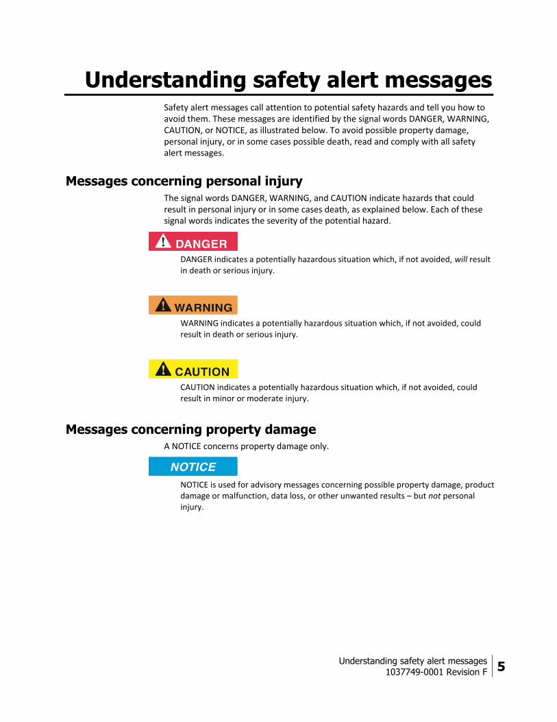
Understanding safety alert messages Safety alert messages call attention to potential safety hazards and tell you how to avoid them. These messages are identified by the signal words DANGER, WARNING, CAUTION, or NOTICE, as illustrated below. To avoid possible property damage, personal injury, or in some cases possible death, read and comply with all safety alert messages.
Messages concerning personal injury The signal words DANGER, WARNING, and CAUTION indicate hazards that could result in personal injury or in some cases death, as explained below. Each of these signal words indicates the severity of the potential hazard.
DANGER indicates a potentially hazardous situation which, if not avoided, will result in death or serious injury.
WARNING indicates a potentially hazardous situation which, if not avoided, could result in death or serious injury.
CAUTION indicates a potentially hazardous situation which, if not avoided, could result in minor or moderate injury.
Messages concerning property damage A NOTICE concerns property damage only.
NOTICE is used for advisory messages concerning possible property damage, product damage or malfunction, data loss, or other unwanted results – but not personal injury.

6 Understanding safety alert messages
1037749-0001 Revision F
Safety symbols The generic safety alert symbol
calls attention to a potential personal injury hazard. It appears next to the DANGER, WARNING, and CAUTION signal words as part of the signal word label. Other symbols may appear next to DANGER, WARNING, or CAUTION to indicate a specific type of hazard (for example, fire or electric shock). If other hazard symbols are used in this document they are identified in this section.
Additional symbols
This document uses the following hazard symbols:
Indicates a safety message that concerns a potential electric
shock hazard.
Indicates a safety message that concerns a potentially
hazardous situation in which you could fall.
Indicates a safety message that concerns radio frequency
(RF) energy.
Understanding safety alert messages
1037749-0001 Revision F 7
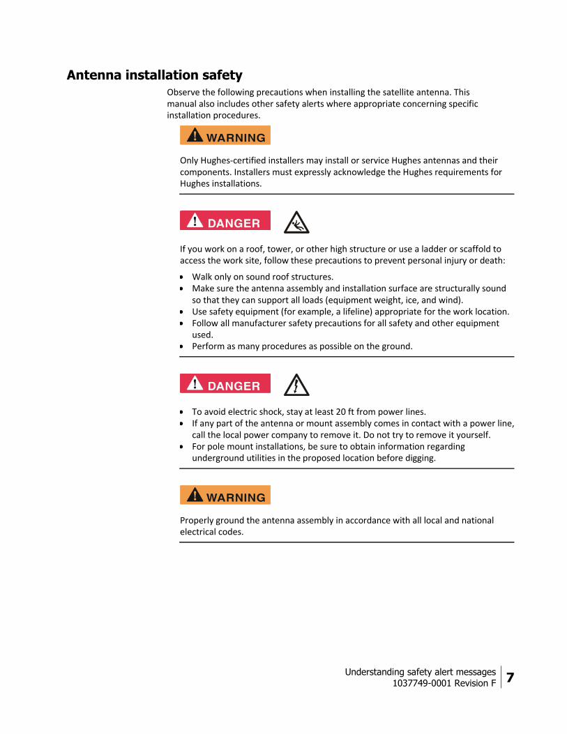
Antenna installation safety Observe the following precautions when installing the satellite antenna. This manual also includes other safety alerts where appropriate concerning specific installation procedures.
Only Hughes‐certified installers may install or service Hughes antennas and their components. Installers must expressly acknowledge the Hughes requirements for Hughes installations.
If you work on a roof, tower, or other high structure or use a ladder or scaffold to access the work site, follow these precautions to prevent personal injury or death:
Walk only on sound roof structures. Make sure the antenna assembly and installation surface are structurally sound
so that they can support all loads (equipment weight, ice, and wind). Use safety equipment (for example, a lifeline) appropriate for the work location. Follow all manufacturer safety precautions for all safety and other equipment
used. Perform as many procedures as possible on the ground.
To avoid electric shock, stay at least 20 ft from power lines. If any part of the antenna or mount assembly comes in contact with a power line,
call the local power company to remove it. Do not try to remove it yourself. For pole mount installations, be sure to obtain information regarding
underground utilities in the proposed location before digging.
Properly ground the antenna assembly in accordance with all local and national electrical codes.

8 Understanding safety alert messages
1037749-0001 Revision F
Do not work in high wind or rain; or if a storm, lightning, or other adverse weather conditions are either present or approaching.
Do not attempt to assemble, move, or mount the antenna on a windy day. Even a slight wind can unexpectedly create sudden strong forces on the antenna surface.
If the antenna or mount assembly begins to fall during the installation, do not attempt to catch it. Move away and let it fall.
Antennas that have been improperly installed or attached to an unstable structure are susceptible to wind damage, which can be very serious or even life threatening. The product owner and installer assume full responsibility that the installation is structurally sound to support all loads (weight, wind, and ice) and is properly sealed against leaks.
Understanding safety alert messages
1037749-0001 Revision F 9
Observe these precautions to avoid exposure to RF radiation, a potential safety hazard:
The antenna must be installed in a location not readily accessible to children and in a manner that prevents human exposure to potentially harmful levels of radiation.
Antennas mounted in Puerto Rico, the continental United States, or at any site with a greater than 30° elevation angle must be installed such that the lower lip of the antenna reflector is at least 5 ft above any surface upon which a person might be expected to stand, and 3 ft 3 inches from any opening (such as a door or window) in a building or adjacent structure.
Antennas mounted in Canada, Alaska, Hawaii, or any site with a less than 30° elevation must be installed such that the lower lip of the antenna reflector is at least 5 ft 9 inches above any surface upon which a person might be expected to stand, and 3 ft 3 inches from any opening (such as a door or window) in a building or adjacent structure.
The antenna must be mounted such that no object that could reasonably be expected to support a person is within 6 ft 7 inches of the edges of a cylindrical space projecting outward from the antenna reflector toward the satellite.
If the above distance requirements cannot be met, the antenna must be mounted in a controlled area inaccessible to the general public, such as a fenced enclosure or a roof.
A fenced installation must have a locked entry, and the fenced area must be large enough to protect the general public from exposure to potentially harmful levels of radiation.
Access to a roof installation in a commercial, industrial, or institutional environment must be limited by a door or a permanently fastened ladder that is locked to deny access to the general public.
Once the transmitter becomes operational, maintain a safe distance; at least 3 feet.
Failure to observe these cautions could result in injury to eyes or other personal injury.

10 Understanding safety alert messages
1037749-0001 Revision F
Observe these precautions to avoid exposure to RF radiation, a potential safety hazard:
All antennas of any type or size must carry an industry standard and government approved Radiation Hazard Caution label on the feed support arm.
A fenced or roof installation in a commercial, industrial, or institutional environment must carry a Radiation Hazard Caution sign on the access door, gate, or permanently mounted access ladder within plain sight of anyone approaching the antenna from the front or sides of the reflector.
Failure to observe these cautions could result in injury to eyes or other personal injury.
Note: Some installations may require additional precautions. See the HughesNet System Antenna Site Preparation and Mount Installation Guide (1035678‐0001) for more information.
Chapter 1 • Overview
1037749-0001 Revision F 11
Chapter 1
Overview This installation guide explains how to assemble and install the Hughes AN8-074P 0.74 m Ka-band antenna. It is written for qualified installers who are familiar with satellite antenna installation practices, and are capable of properly applying the information presented.
This chapter includes the following sections:
Model AN8-074P antenna description on page 12 Antenna installation summary on page 13 Tasks related to antenna installation on page 14
12 Chapter 1 • Overview
1037749-0001 Revision F
Model AN8-074P antenna description
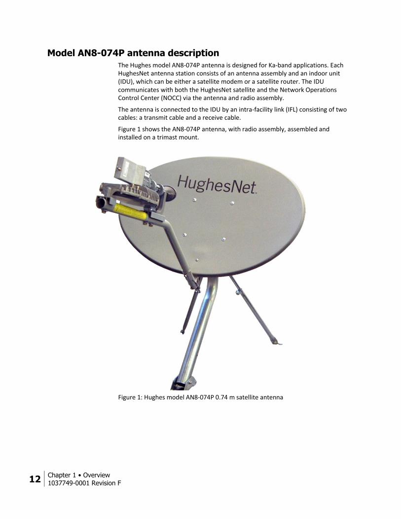
The Hughes model AN8-074P antenna is designed for Ka-band applications. Each HughesNet antenna station consists of an antenna assembly and an indoor unit (IDU), which can be either a satellite modem or a satellite router. The IDU communicates with both the HughesNet satellite and the Network Operations Control Center (NOCC) via the antenna and radio assembly.
The antenna is connected to the IDU by an intra-facility link (IFL) consisting of two cables: a transmit cable and a receive cable.
Figure 1 shows the AN8-074P antenna, with radio assembly, assembled and installed on a trimast mount.
Figure 1: Hughes model AN8-074P 0.74 m satellite antenna

Chapter 1 • Overview
1037749-0001 Revision F 13
Antenna installation summary
This section lists the basic steps and related tasks for installing the satellite antenna. Follow all steps in the order in which they are presented here and elsewhere in this guide. For detailed information on each task, refer to the listed section or chapter in this guide or other listed documents.
Table 1: Satellite antenna installation summary
Task For details, see…
1 Explain the installation process to the customer.
2 Conduct a site survey with the customer to identify a suitable location for the antenna.
Selecting the installation site on page 14 and Antenna Site Preparation and Mount Installation Guide (1035678-0001)
3 Power on and install the IDU.
Note: You must install the IDU before installing the antenna so you can determine the antenna pointing values (azimuth, elevation and tilt).
IDU installation guide
4 Determine the most suitable method for mounting the antenna; then install the antenna mast.
Note: The antenna mast must be plumb. The antenna cannot be adjusted to correct for a mast that is not plumb.
Installing the antenna mount on page 14 and Antenna Site Preparation and Mount Installation Guide (1035678-0001)
5 Assemble the antenna (Az/El mount, feed support arms, reflector, and other parts).
Chapter 3 – Installing the antenna and radio assembly on page 25
6 Install the radio assembly and feed horn. Installing the radio assembly on page 31 Installing the feed horn on page 36
7 Install the antenna assembly on the mast. Installing the antenna assembly onto the mast on page 39
8 Install the IFL transmit and receive cables between the IDU and the antenna.
Chapter 4 – Cabling and connections on page 43
9 Ground the antenna assembly. Grounding on page 45
10 Point the antenna. Pointing procedure: Ka-Band Antenna Pointing Guide (1037663-0001)
Mechanical adjustments for pointing:
Chapter 5 – Adjusting antenna azimuth and elevation
When the antenna is properly pointed you can commission the IDU as instructed in the IDU installation guide.

14 Chapter 1 • Overview
1037749-0001 Revision F
Tasks related to antenna installation
This section discusses tasks related to antenna installation and explains where to find additional information.
Selecting the installation site
Before selecting an installation site, check the installation reference sheet to see if a customer-specific installation site has been pre-determined and specified. Also, refer to the HughesNet Antenna Site Preparation and Mount Installation Guide (1035678-0001), which discusses the factors that you should consider when selecting an antenna installation site.
The first and most important consideration when choosing a prospective antenna site is whether the area can provide an acceptable line of sight (LOS) to the satellite. A site with a clear, unobstructed view of the southern sky is necessary. Also, consider obstructions that may occur in the future, such as the growth of trees. Select your antenna site before performing the installation, so that the antenna will be able to receive the strongest signal available.
As with any type of construction, a local building permit may be required before installing the antenna. It is the property owner's responsibility to obtain necessary permits and comply with local building codes.
Installing the antenna mount
Before installing the antenna itself, you must first install a suitable antenna mount. If the system requires a pole mount installation, be sure to obtain information about the underground utilities in the proposed location. Have the appropriate utility company mark the location of any underground telephone wires, storm drains, etc. Also, because soils vary widely in composition and load capacity, it may be necessary to consult a local professional engineer to determine the appropriate foundation design.
For pole mounts that require a concrete base, you must allow at least 24 hr for the concrete to cure before installing the antenna. Be sure to plan and schedule the installation accordingly.
For complete information regarding antenna mount installation, including various mounting methods, refer to:
The customer-specific installation reference sheet The HughesNet Antenna Site Preparation and Mount Installation Guide
(1035678-0001)
Refer to the installation reference sheet for any customer-specific guidelines concerning the mount installation. Use only the installation method described in the reference sheet.
If the installation reference sheet does not specify a method, use only the mount installation methods documented in the HughesNet Antenna Site Preparation and Mount Installation Guide (1035678-0001). Most installations in a commercial, industrial, or institutional environment use a non-penetrating roof mount.

Chapter 1 • Overview
1037749-0001 Revision F 15
Installing the IDU
See the installation guide for the specific IDU you are installing.
Grounding
The antenna assembly must be grounded. For grounding information, refer to your training, best grounding practices, the Hughes Field Service Bulletin (FSB) HNS Broadband Requirements for RG-6 and RG-11 IFL Cable Connectors, Ground Blocks and Ground Block Location (FSB 050518_01), and applicable parts of the National Electrical Code (NEC).
Approved cables
For a list of approved coaxial cable types for the IFL between the antenna and the IDU, see the Hughes FSB, IFL Cable, Approved List (with lengths) for SPACEWAY Domestic Installations (FSB 080202_01). The FSB lists the maximum cable length for each approved cable type for all relevant radio types.
Because it is impossible to predict the requirements specific to each installation site, you must use your own judgment and best practices to determine how to route and connect the IFL transmit and receive cables.

Antenna parts and recommended tools
1037749-0001 Revision F 17
Chapter 2
Antenna parts and recommended tools This chapter identifies the main components and parts provided with the AN8-074P Ka-band antenna kit. It includes the following sections:
Antenna kit components Small hardware parts list on page 22 Tools on page 23
Antenna kit components When you receive the equipment, unpack and inspect the antenna components and hardware to make sure all parts have been received in good condition.
Metal components may contain sharp edges. Use care when unpacking and handling antenna parts.
If any parts appear to have been damaged in transit, immediately contact the freight carrier. If any parts appear to be missing or damaged, but not as a result of handling in transit, contact your dealer or distributor.
The antenna kit is shipped in two boxes; the radio assembly is shipped separately in a third box.
Note: To avoid potential damage, leave all components in their protective packages until required.
18 Antenna parts and recommended tools
1037749-0001 Revision F
The main components of the antenna kit are:
Az/El mount assembly Reflector bracket and tilt plate Antenna reflector Feed support arm Radio assembly (shipped separately) Feed horn
The following sections describe and illustrate each component of the antenna kit.
Az/El mount assembly
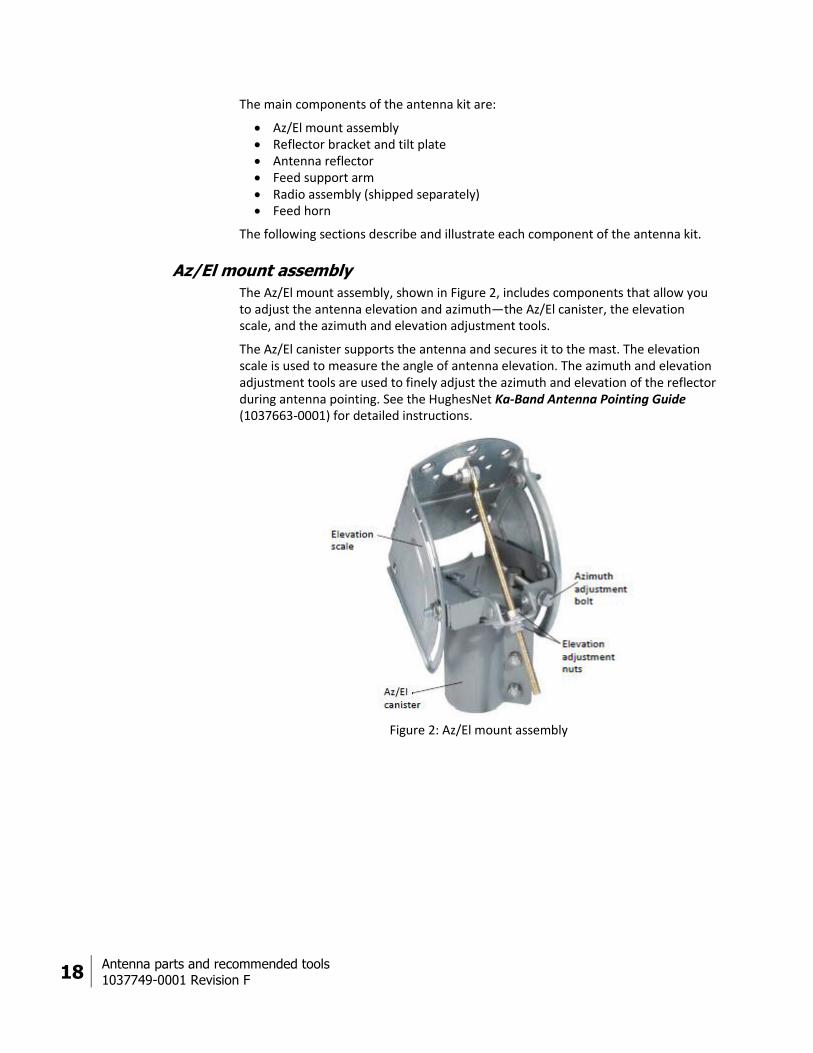
The Az/El mount assembly, shown in Figure 2, includes components that allow you to adjust the antenna elevation and azimuth—the Az/El canister, the elevation scale, and the azimuth and elevation adjustment tools.
The Az/El canister supports the antenna and secures it to the mast. The elevation scale is used to measure the angle of antenna elevation. The azimuth and elevation adjustment tools are used to finely adjust the azimuth and elevation of the reflector during antenna pointing. See the HughesNet Ka-Band Antenna Pointing Guide (1037663-0001) for detailed instructions.
Figure 2: Az/El mount assembly

Antenna parts and recommended tools
1037749-0001 Revision F 19
Reflector bracket and tilt plate
The reflector bracket shown in Figure 3 attaches to the Az/El mount and supports the antenna reflector. The reflector bracket and tilt plate allow the reflector to rotate so it can be adjusted for proper tilt. (See also Figure 9 on page 27.)
Figure 3: Reflector bracket and tilt plate
Antenna reflector
The antenna reflector shown in Figure 4 focuses the transmitted and received RF signals. It attaches to the reflector bracket.
Figure 4: Antenna reflector

20 Antenna parts and recommended tools
1037749-0001 Revision F
Handle the antenna reflector with care to avoid bending it or other damage.
Feed support arm
Figure 5 shows the feed support arm, which supports the radio assembly and feed horn.
Figure 5: Feed support arm
Radio assembly
The radio assembly shown in Figure 6 consists of the radio transmitter, low noise block converter (LNB), transmit/receive isolation assembly (TRIA), and polarizer (waveguide).
Figure 6: Radio assembly

Antenna parts and recommended tools
1037749-0001 Revision F 21
Feed horn
The elliptical feed horn, shown in Figure 7, attaches to the polarizer on the radio assembly.
Figure 7: Feed horn
Polarizer clamps
Two identical clamps with spring-loaded screws attach to each end of the radio polarizer. One clamp (pre-installed) secures the polarizer to the TRIA; the other (shipped in the radio assembly box) secures the feed horn stem to the polarizer
Figure 8: Polarizer clamps

22 Antenna parts and recommended tools
1037749-0001 Revision F
Small hardware parts list
Table 2 lists the small hardware parts included with the antenna kit and radio assembly.
Table 2: Small hardware parts
Hardware in second column is used to attach…
Hardware parts Quantity Illustration showing where parts are used
Reflector bracket and tilt plate to Az/El mount assembly
5/16 inch × ¾ inch carriage bolts 5 Figure 9 on page 27
5/16 inch hex head serrated flange nuts
5
Antenna reflector to reflector bracket
5/16 inch × ¾ inch carriage bolts 4 Figure 11 on page 29
5/16 inch hex head serrated flange nuts
4
¼ inch × ½ inch Phillips head screw 1
Feed support arm to reflector bracket
¼ inch × 1¾ inch hex bolts 2 Figure 12 on page 30
¼ inch flat washers 2
¼ inch lock washers 2
¼ inch hex nuts 2
Feed horn support bracket and long adapter bracket to feed support arm
¼ inch × 1¾ inch hex bolt 1 Figure 13 on page 31
¼ inch flat washer 1
¼ inch lock washer 1
Radio assembly (transmitter) and short adapter bracket to feed support arm
5/16 inch × 1¾ inch hex bolts 2 Figure 14 on page 31 and Figure 15 on page 32
5/16 inch flat washers 2
5/16 inch lock washers 2
Feed horn to radio assembly O-ring 1 Figure 21 on page 37
#6-32 hexagonal socket head (Allen) screws
4
#4-40 x ½ inch Phillips head screws 2
Antenna parts and recommended tools
1037749-0001 Revision F 23
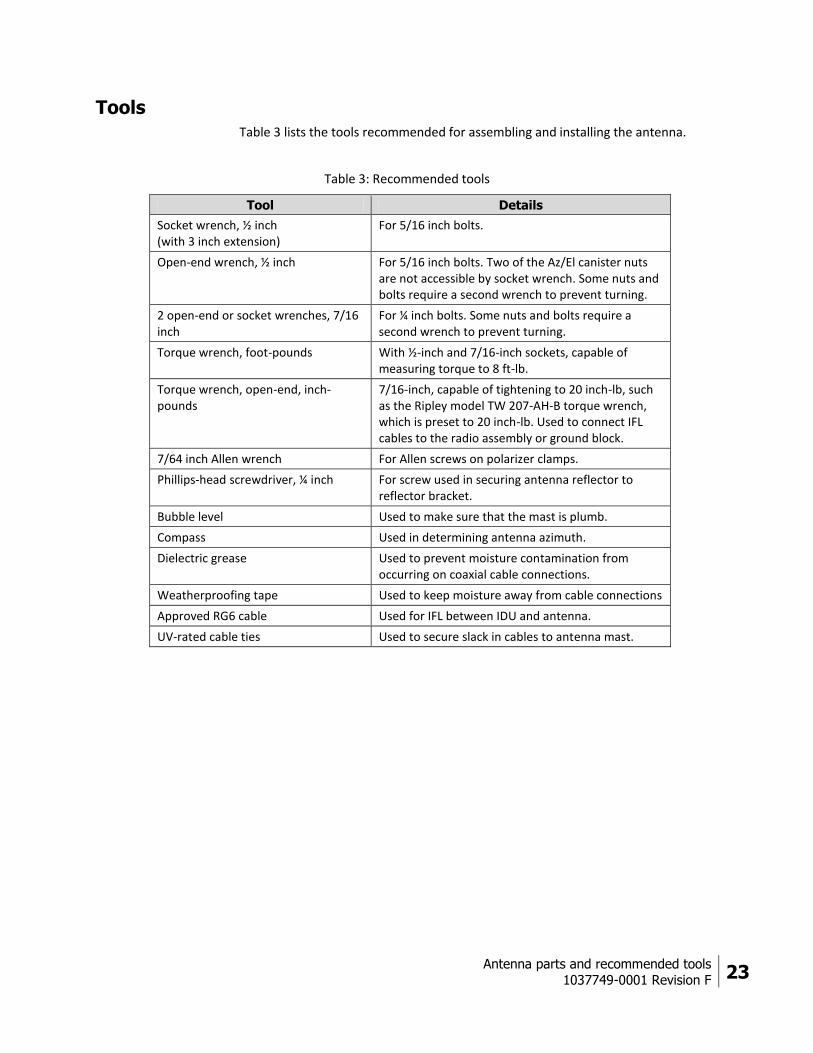
Tools Table 3 lists the tools recommended for assembling and installing the antenna.
Table 3: Recommended tools
Tool Details
Socket wrench, ½ inch (with 3 inch extension)
For 5/16 inch bolts.
Open-end wrench, ½ inch For 5/16 inch bolts. Two of the Az/El canister nuts are not accessible by socket wrench. Some nuts and bolts require a second wrench to prevent turning.
2 open-end or socket wrenches, 7/16 inch
For ¼ inch bolts. Some nuts and bolts require a second wrench to prevent turning.
Torque wrench, foot-pounds With ½-inch and 7/16-inch sockets, capable of measuring torque to 8 ft-lb.
Torque wrench, open-end, inch-pounds
7/16-inch, capable of tightening to 20 inch-lb, such as the Ripley model TW 207-AH-B torque wrench, which is preset to 20 inch-lb. Used to connect IFL cables to the radio assembly or ground block.
7/64 inch Allen wrench For Allen screws on polarizer clamps.
Phillips-head screwdriver, ¼ inch For screw used in securing antenna reflector to reflector bracket.
Bubble level Used to make sure that the mast is plumb.
Compass Used in determining antenna azimuth.
Dielectric grease Used to prevent moisture contamination from occurring on coaxial cable connections.
Weatherproofing tape Used to keep moisture away from cable connections
Approved RG6 cable Used for IFL between IDU and antenna.
UV-rated cable ties Used to secure slack in cables to antenna mast.

Installing the antenna and radio assembly
1037749-0001 Revision F 25
Chapter 3
Installing the antenna and radio assembly
This chapter explains how to assemble and install the antenna, radio assembly, and associated hardware. It includes these topics:
Determining the pointing values General instructions for assembling the antenna on page 26 Installing the reflector bracket and tilt plate on page 27 Installing the antenna reflector on page 28 Installing the feed support arm on page 30 Installing the radio assembly on page 31 Installing the feed horn on page 36 Installing the antenna assembly onto the mast on page 39
Before you install the antenna, read all safety information in Understanding safety alert messages on page 5.
Determining the pointing values Before installing the antenna, you must install and power up the IDU. Refer to the appropriate IDU installation guide for instructions.
Once the IDU is fully powered up, connect it to your laptop using an Ethernet cable, then use your global positioning system (GPS) receiver to calculate the exact latitude and longitude of the antenna site. Follow the instructions in the HughesNet System Ka-Band Antenna Pointing Guide (1037663-0001) to enter the latitude and longitude information to determine the initial antenna azimuth, elevation, and tilt values. Record these values and keep them handy for reference as you install and point the antenna.

26 Installing the antenna and radio assembly
1037749-0001 Revision F
General instructions for assembling the antenna Before you assemble the antenna, read these important instructions:
Mast – The antenna mast must be installed before you can install the antenna. For information on installing the mast, see the HughesNet System Antenna Site Preparation and Mount Installation Guide (1035678-0001).
Note: The mast diameter must be 2.5 inch nominal pipe size (2.88 inch outside diameter).
Sequence of steps – When you assemble the antenna, be sure to follow the instructions in this chapter in the order they are presented.
For rooftop installations, assemble the antenna on the ground and then carry the fully assembled antenna up to the roof.
Tightening hardware – Do not tighten any nuts or other hardware until instructed to do so. (See also the next item, Torque.)
Torque – To ensure successful installation of the antenna, it is critical that you tighten all nuts and socket-head screws to the torque values shown in Table 4.
Table 4: Torque values
Fastener or connector Proper torque value
5/16 inch bolts 8 ft-lb
1/4 inch bolts 5 ft-lb
IFL cable connectors for connection to the radio and ground block
20 inch-lb
Installing the antenna and radio assembly
1037749-0001 Revision F 27
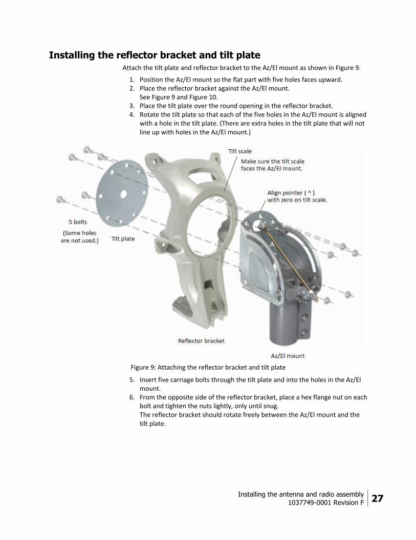
Installing the reflector bracket and tilt plate Attach the tilt plate and reflector bracket to the Az/El mount as shown in Figure 9.
1. Position the Az/El mount so the flat part with five holes faces upward. 2. Place the reflector bracket against the Az/El mount.
See Figure 9 and Figure 10. 3. Place the tilt plate over the round opening in the reflector bracket. 4. Rotate the tilt plate so that each of the five holes in the Az/El mount is aligned
with a hole in the tilt plate. (There are extra holes in the tilt plate that will not line up with holes in the Az/El mount.)
Figure 9: Attaching the reflector bracket and tilt plate
5. Insert five carriage bolts through the tilt plate and into the holes in the Az/El mount.
6. From the opposite side of the reflector bracket, place a hex flange nut on each bolt and tighten the nuts lightly, only until snug. The reflector bracket should rotate freely between the Az/El mount and the tilt plate.
28 Installing the antenna and radio assembly
1037749-0001 Revision F
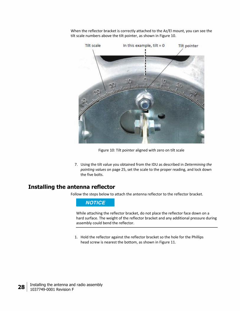
When the reflector bracket is correctly attached to the Az/El mount, you can see the tilt scale numbers above the tilt pointer, as shown in Figure 10.
Figure 10: Tilt pointer aligned with zero on tilt scale
7. Using the tilt value you obtained from the IDU as described in Determining the pointing values on page 25, set the scale to the proper reading, and lock down the five bolts.
Installing the antenna reflector Follow the steps below to attach the antenna reflector to the reflector bracket.
While attaching the reflector bracket, do not place the reflector face down on a hard surface. The weight of the reflector bracket and any additional pressure during assembly could bend the reflector.
1. Hold the reflector against the reflector bracket so the hole for the Phillips head screw is nearest the bottom, as shown in Figure 11.

Installing the antenna and radio assembly
1037749-0001 Revision F 29
2. Insert four carriage bolts (5/16 inch × ¾ inch) into the holes in the reflector and through the corresponding holes in the reflector bracket, as shown in the illustration.
Figure 11: Attaching the antenna reflector
3. Insert the Phillips head screw through the hole near the bottom of the reflector and into the corresponding hole in the reflector bracket—but do not tighten this screw yet.
4. From the back of the reflector bracket, secure the four bolts with four ½ inch hex flange nuts and tighten the nuts.
Note: Make sure the carriage bolts are firmly seated before tightening the nuts.
5. Tighten the Phillips head screw.
30 Installing the antenna and radio assembly
1037749-0001 Revision F
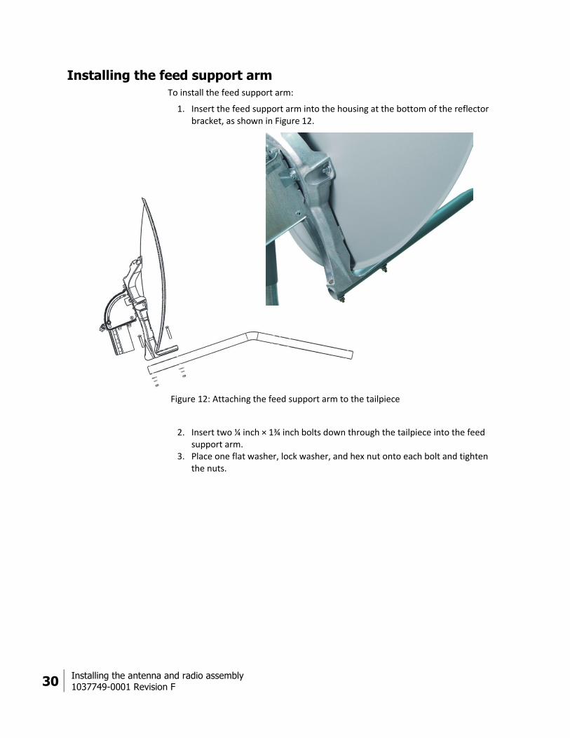
Installing the feed support arm To install the feed support arm:
1. Insert the feed support arm into the housing at the bottom of the reflector bracket, as shown in Figure 12.
Figure 12: Attaching the feed support arm to the tailpiece
2. Insert two ¼ inch × 1¾ inch bolts down through the tailpiece into the feed support arm.
3. Place one flat washer, lock washer, and hex nut onto each bolt and tighten the nuts.

Installing the antenna and radio assembly
1037749-0001 Revision F 31
Installing the radio assembly To mount the radio assembly to the feed support arm:
1. Insert a single 5/16 inch × 1¾ inch bolt, with flat washer and lock washer up through the feed support arm from underneath.
2. Position the long adapter bracket and feed horn support bracket on the feed support arm (as shown in Figure 13) so the bolt passes through the long bracket and into the feed horn bracket.
Figure 13: Positioning the radio and feed horn brackets
3. Tighten the bolt. 4. Position the radio assembly above the long adapter bracket so that the
polarizer on the radio is nearest to the reflector, as shown in Figure 14.
Figure 14: Attaching the radio assembly

32 Installing the antenna and radio assembly
1037749-0001 Revision F
5. Insert one 5/16 inch × 1¾ inch bolt, with flat washer and lock washer up through the feed support arm and long adapter bracket, and into the threaded socket on the front of the transmitter.
6. Tighten only enough to hold the radio in place.
Tighten the nut only enough to secure the radio and adapter bracket to the feed support arm. Excessive tightening of this nut can crack or crush the adapter bracket.
7. Place the short adapter bracket in position near the end of the feed support arm and lower the radio onto it as shown in Figure 15.
Figure 15: Securing the rear of the radio assembly
8. Insert one 5/16 inch × 1¾ inch bolt, with flat washer and lock washer, up through the feed support arm and the short adapter bracket, into the threaded socket at the rear of the transmitter.
9. Tighten the bolt to secure the adapter bracket and radio to the feed support arm. Tighten only until snug.
Tighten the nut only enough to secure the radio and adapter bracket to the feed support arm. Excessive tightening of this nut can crack or crush the adapter bracket.
Installing the antenna and radio assembly
1037749-0001 Revision F 33
Changing transmit circular polarization (if needed)
The radio may be shipped with the polarizer set for left-hand circular polarization (LHCP) or right-hand circular polarization (RHCP). There is no default setting. If the radio polarization setting does not match the polarization specified on the installation reference sheet, you will have to change the setting.
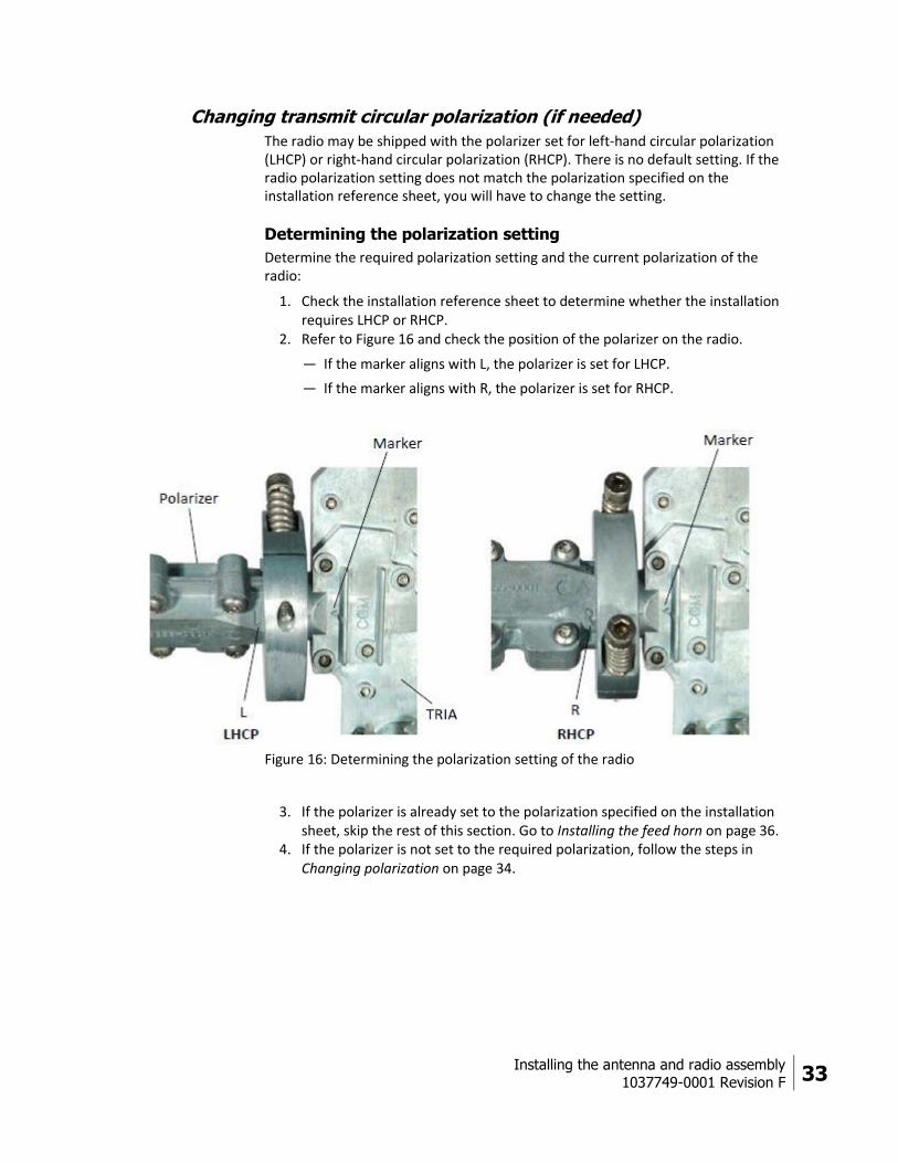
Determining the polarization setting
Determine the required polarization setting and the current polarization of the radio:
1. Check the installation reference sheet to determine whether the installation requires LHCP or RHCP.
2. Refer to Figure 16 and check the position of the polarizer on the radio.
— If the marker aligns with L, the polarizer is set for LHCP.
— If the marker aligns with R, the polarizer is set for RHCP.
Figure 16: Determining the polarization setting of the radio
3. If the polarizer is already set to the polarization specified on the installation sheet, skip the rest of this section. Go to Installing the feed horn on page 36.
4. If the polarizer is not set to the required polarization, follow the steps in Changing polarization on page 34.
34 Installing the antenna and radio assembly
1037749-0001 Revision F
Changing polarization
Follow the instructions in this section only if you need to change transmit circular polarization from LHCP to RHCP or from RHCP to LHCP.
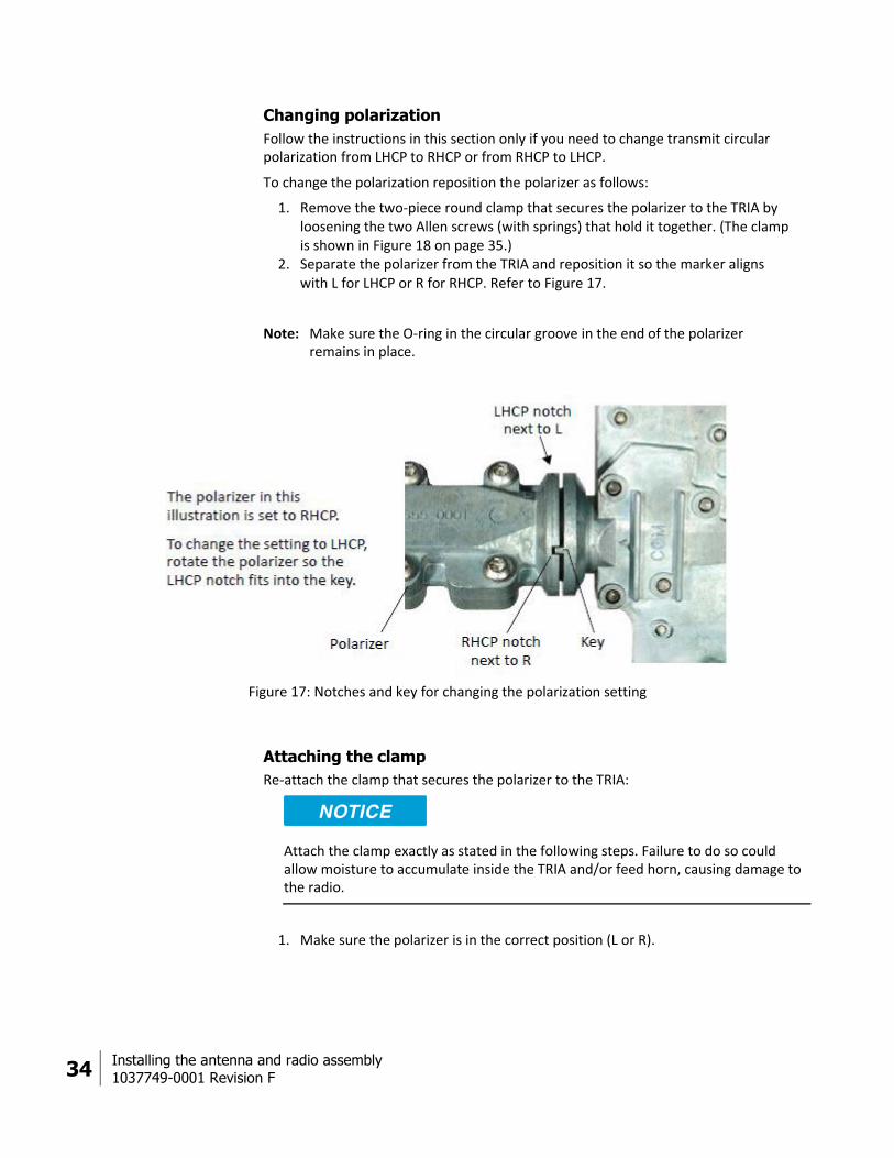
To change the polarization reposition the polarizer as follows:
1. Remove the two-piece round clamp that secures the polarizer to the TRIA by loosening the two Allen screws (with springs) that hold it together. (The clamp is shown in Figure 18 on page 35.)
2. Separate the polarizer from the TRIA and reposition it so the marker aligns with L for LHCP or R for RHCP. Refer to Figure 17.
Note: Make sure the O-ring in the circular groove in the end of the polarizer remains in place.
Figure 17: Notches and key for changing the polarization setting
Attaching the clamp
Re-attach the clamp that secures the polarizer to the TRIA:
Attach the clamp exactly as stated in the following steps. Failure to do so could allow moisture to accumulate inside the TRIA and/or feed horn, causing damage to the radio.
1. Make sure the polarizer is in the correct position (L or R).

Installing the antenna and radio assembly
1037749-0001 Revision F 35
2. Position the clamp half that has two threaded holes against the polarizer-TRIA interface, as shown in Figure 18 (left photo).
Figure 18: Attaching the clamp that holds the polarizer in place
3. Position the other clamp half (with holes that are not threaded) against the clamp half that is already in place.
4. Start each screw (spring-loaded Allen screws) by hand, being careful not to cross-thread them. Because the screws are long, they can easily be cross-threaded if they are misaligned. If the screw does not turn easily when first inserted, back it out and start again.
5. Use a 7/64 inch Allen wrench—do not use a power driver—to alternately tighten the two screws. When you hear a click, the screw is fully tightened and should not be turned further.
36 Installing the antenna and radio assembly
1037749-0001 Revision F
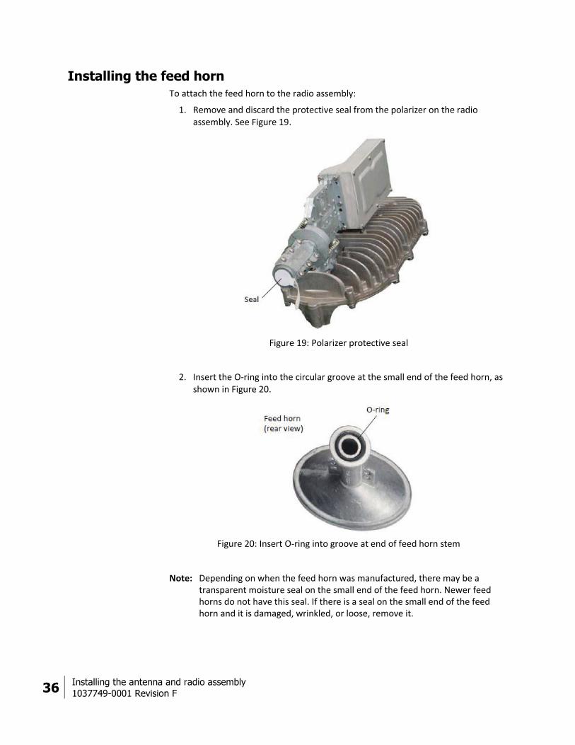
Installing the feed horn To attach the feed horn to the radio assembly:
1. Remove and discard the protective seal from the polarizer on the radio assembly. See Figure 19.
Figure 19: Polarizer protective seal
2. Insert the O-ring into the circular groove at the small end of the feed horn, as shown in Figure 20.
Figure 20: Insert O-ring into groove at end of feed horn stem
Note: Depending on when the feed horn was manufactured, there may be a transparent moisture seal on the small end of the feed horn. Newer feed horns do not have this seal. If there is a seal on the small end of the feed horn and it is damaged, wrinkled, or loose, remove it.

Installing the antenna and radio assembly
1037749-0001 Revision F 37
3. If you previously changed the radio polarization setting, the polarizer clamp next to the TRIA (shown in Figure 21, upper left) should be loose. If the clamp is not loose, loosen it now by loosening the two Allen screws.
4. Perform steps a and b at the same time:
a. Fit the feed horn stem against the polarizer, as shown in Figure 21. The polarizer end fits into the feed horn stem.
Figure 21: Place the feed horn on the support bracket
b. Place the feed horn onto the feed horn support bracket so the two holes nearest the feed horn fit into the pegs on each side of the bracket.
Note: If you have difficulty, loosen the clamp where the polarizer joins the TRIA, or loosen it more.
Attaching the clamp
With the feed horn in place, attach the clamp that secures the feed horn to the polarizer.
Attach the clamp exactly as stated in the following steps. Failure to do so could allow moisture to accumulate inside the TRIA and/or feed horn, causing damage to the radio.

38 Installing the antenna and radio assembly
1037749-0001 Revision F
1. Position the clamp half that has two threaded holes against the interface where the feed horn stem mates to the polarizer, as shown in Figure 22 (left photo).
Figure 22: Attaching the clamp over the end of the feed horn
2. Position the other clamp half (with holes that are not threaded) against the clamp half that is already in place.
3. Start each screw (spring-loaded Allen screws) by hand, being careful not to cross-thread them. Because the screws are long, they can easily be cross-threaded if they are misaligned. If the screw does not turn easily when first inserted, back it out and start again.
4. Use a 7/64 inch Allen wrench—do not use a power driver—to alternately tighten the two screws on the feed horn clamp. When you hear a click, the screw is fully tightened and should not be turned further.
Note: When the screws are tight, the clamp halves do not touch each other. This is normal.
Installing the antenna and radio assembly
1037749-0001 Revision F 39
Securing the feed horn
Secure the feed horn to the feed horn support bracket:
1. Insert the two mounting screws through the remaining two holes on each side of the feed horn stem.
2. Tighten the screws with a ¼ inch Phillips head screwdriver. 3. Fully tighten any hardware that is not tight—except, leave nuts that are used
for pointing adjustments just snug.
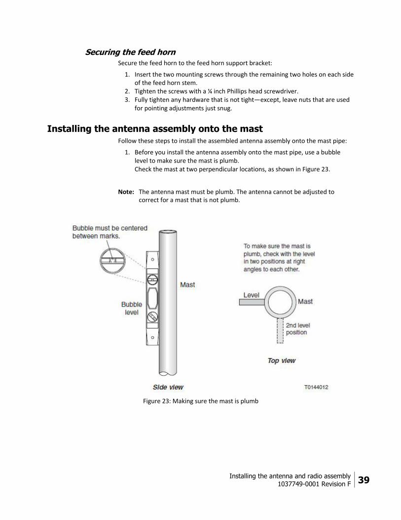
Installing the antenna assembly onto the mast Follow these steps to install the assembled antenna assembly onto the mast pipe:
1. Before you install the antenna assembly onto the mast pipe, use a bubble level to make sure the mast is plumb. Check the mast at two perpendicular locations, as shown in Figure 23.
Note: The antenna mast must be plumb. The antenna cannot be adjusted to correct for a mast that is not plumb.
Figure 23: Making sure the mast is plumb
40 Installing the antenna and radio assembly
1037749-0001 Revision F
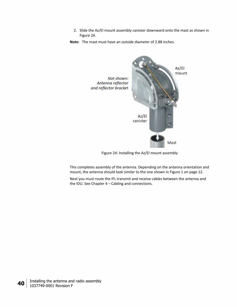
2. Slide the Az/El mount assembly canister downward onto the mast as shown in Figure 24.
Note: The mast must have an outside diameter of 2.88 inches.
Figure 24: Installing the Az/El mount assembly
This completes assembly of the antenna. Depending on the antenna orientation and mount, the antenna should look similar to the one shown in Figure 1 on page 12.
Next you must route the IFL transmit and receive cables between the antenna and the IDU. See Chapter 4 – Cabling and connections.
Cabling and connections
1037749-0001 Revision F 41
Chapter 4
Cabling and connections This chapter illustrates where the antenna transmit and receive connectors are located; describes how to route the transmit (Tx) and receive (Rx) cables at the antenna; and explains how to connect the transmit and receive cables to the radio assembly. You must connect all of these cables before you can point the antenna at the HughesNet system satellite.
Topics in this chapter include:
Cabling requirements Routing the cables at the antenna on page 42 Connecting the transmit and receive cables on page 44 Ground connection on page 45 Pointing on page 45
Cabling requirements For a list of approved coaxial cable types for the IFL between the antenna and the IDU, see the Hughes FSB, IFL Cable, Approved List (with lengths) for SPACEWAY Domestic Installations (FSB 080202_01). The FSB lists the maximum cable length for each approved cable type for all relevant radio types.
Because it is impossible to predict the requirements specific to each installation site, you must use your own judgment and best practices to determine how to route the IFL cables.
Coaxial cables and connectors can corrode if exposed to moisture. Use only compression type connectors, and weatherproof them with dielectric grease and weatherproofing tape.
Note: For connector and ground block requirements, see the Hughes FSB, HN Broadband Requirements for RG-6 and RG-11 IFL Cable Connectors, Ground Blocks and Ground Block Location (FSB 50518_01).
42 Cabling and connections
1037749-0001 Revision F
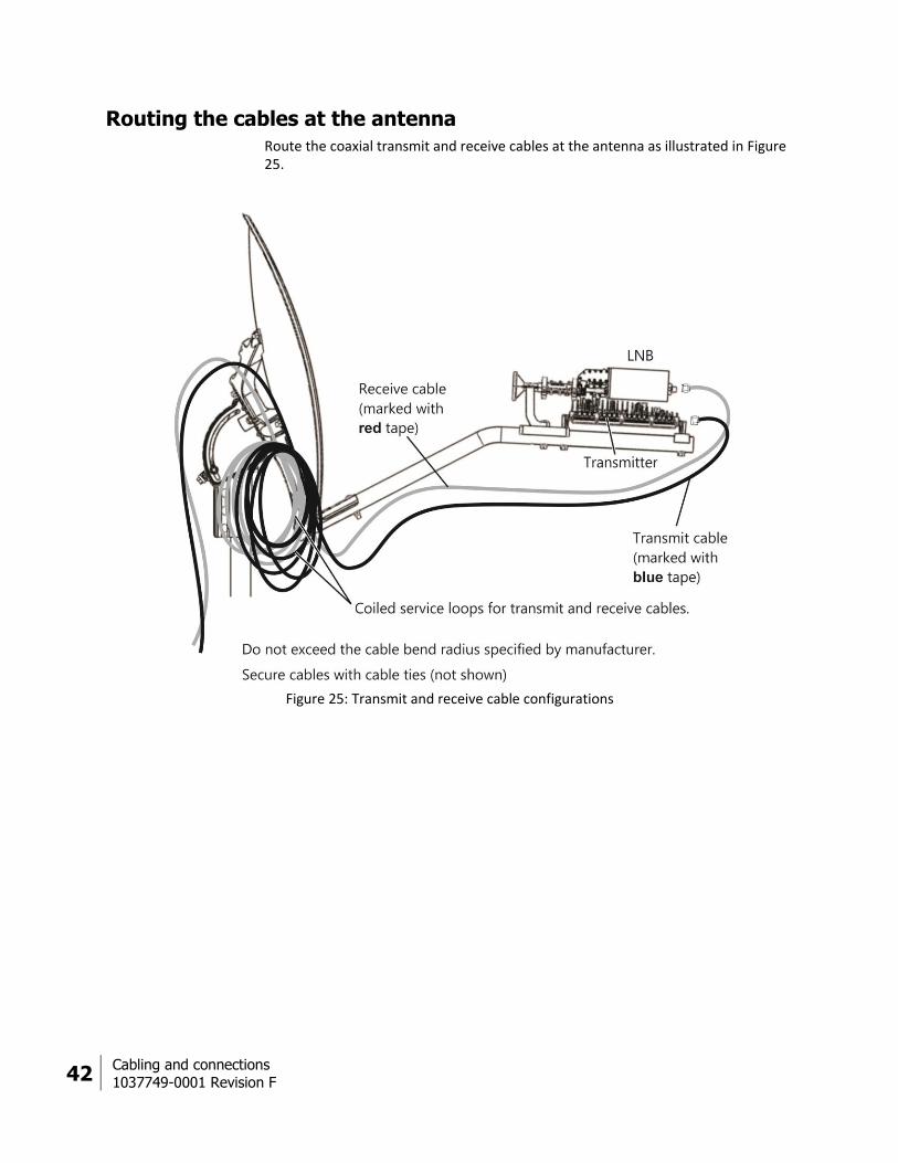
Routing the cables at the antenna
Route the coaxial transmit and receive cables at the antenna as illustrated in Figure 25.
Figure 25: Transmit and receive cable configurations

Cabling and connections
1037749-0001 Revision F 43
Routing the transmit cable
1. Route the transmit cable (marked with blue electrical tape) over the Az/El mount assembly, down behind the reflector, and along the feed support arm to the rear of the transmitter, in a configuration similar to that shown in Figure 25 on page 42.
2. Leave a 10 ft coiled service loop and secure it either to the mast, Az/El mount assembly, or reflector bracket.
Note:
Do not leave the service loop lying on the roof or other mounting surface. Do not block access to the azimuth and elevation adjustment nuts on the
Az/El mount assembly.
3. Coil any extra cable, and secure the transmit cable with cable ties.
Where IFL cables connect to the radio or to a ground block, tighten the cable connector to the torque specified in Table 4 on page 26. Overtightening the radio connectors can result in damage to the radio assembly.
Routing the receive cable
1. Route the receive cable (marked with red electrical tape) over the Az/El mount assembly, down behind the reflector, and along the feed support arm to the LNB, in a configuration similar to that shown in Figure 25 on page 42.
2. Leave a 10 ft coiled service loop and secure it to either the mast, Az/El mount assembly, or reflector bracket.
3. Coil any extra cable, and secure the receive cable with cable ties.
44 Cabling and connections
1037749-0001 Revision F
Connecting the transmit and receive cables
This section explains how to connect the transmit and receive cables to the radio assembly at the antenna.
Because the antenna pointing procedure requires that you disconnect the receive cable, wait until pointing is complete before taping the outdoor connections.
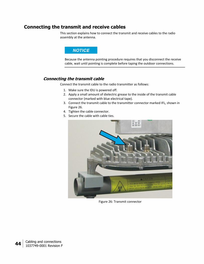
Connecting the transmit cable
Connect the transmit cable to the radio transmitter as follows:
1. Make sure the IDU is powered off. 2. Apply a small amount of dielectric grease to the inside of the transmit cable
connector (marked with blue electrical tape). 3. Connect the transmit cable to the transmitter connector marked IFL, shown in
Figure 26. 4. Tighten the cable connector. 5. Secure the cable with cable ties.
Figure 26: Transmit connector
Cabling and connections
1037749-0001 Revision F 45
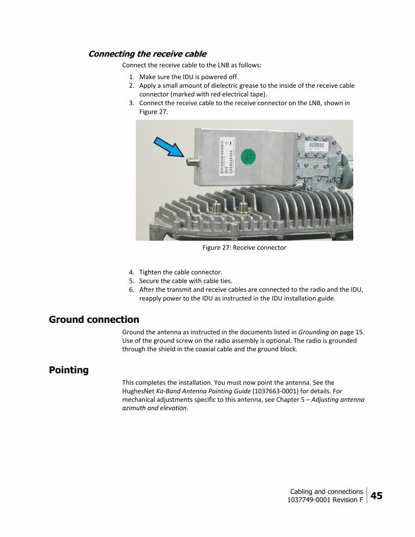
Connecting the receive cable
Connect the receive cable to the LNB as follows:
1. Make sure the IDU is powered off. 2. Apply a small amount of dielectric grease to the inside of the receive cable
connector (marked with red electrical tape). 3. Connect the receive cable to the receive connector on the LNB, shown in
Figure 27.
Figure 27: Receive connector
4. Tighten the cable connector. 5. Secure the cable with cable ties. 6. After the transmit and receive cables are connected to the radio and the IDU,
reapply power to the IDU as instructed in the IDU installation guide.
Ground connection Ground the antenna as instructed in the documents listed in Grounding on page 15. Use of the ground screw on the radio assembly is optional. The radio is grounded through the shield in the coaxial cable and the ground block.
Pointing This completes the installation. You must now point the antenna. See the HughesNet Ka-Band Antenna Pointing Guide (1037663-0001) for details. For mechanical adjustments specific to this antenna, see Chapter 5 – Adjusting antenna azimuth and elevation.

Adjusting antenna azimuth and elevation
1037749-0001 Revision F 47
Chapter 5
Adjusting antenna azimuth and elevation
This chapter explains how to adjust the antenna azimuth and elevation for optimum transmission and reception. It explains the mechanical adjustments only.
For explanation of the pointing process for this antenna, see the HughesNet Ka-Band Antenna Pointing Guide (1037663-0001). To successfully point the antenna, you must follow the procedure detailed in the pointing guide.
This chapter contains the following sections:
Adjusting elevation on page 48 Adjusting azimuth on page 50 Final steps on page 53
Do not try to make antenna pointing adjustments by pulling on the antenna reflector or feed support arm. Doing so could cause permanent damage to the antenna. Instead use the adjustment mechanisms and procedures described in this chapter.
48 Adjusting antenna azimuth and elevation
1037749-0001 Revision F
Adjusting elevation
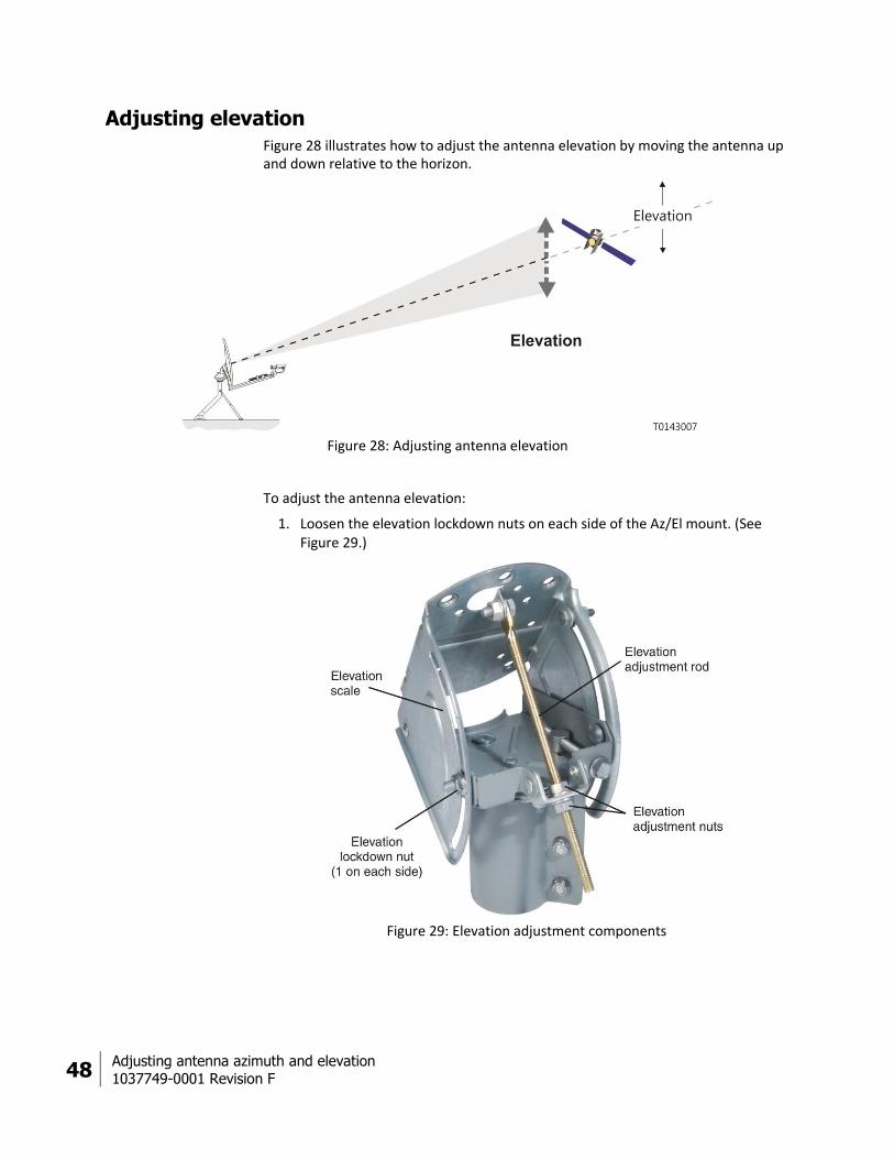
Figure 28 illustrates how to adjust the antenna elevation by moving the antenna up and down relative to the horizon.
Figure 28: Adjusting antenna elevation
To adjust the antenna elevation:
1. Loosen the elevation lockdown nuts on each side of the Az/El mount. (See Figure 29.)
Figure 29: Elevation adjustment components
Adjusting antenna azimuth and elevation
1037749-0001 Revision F 49
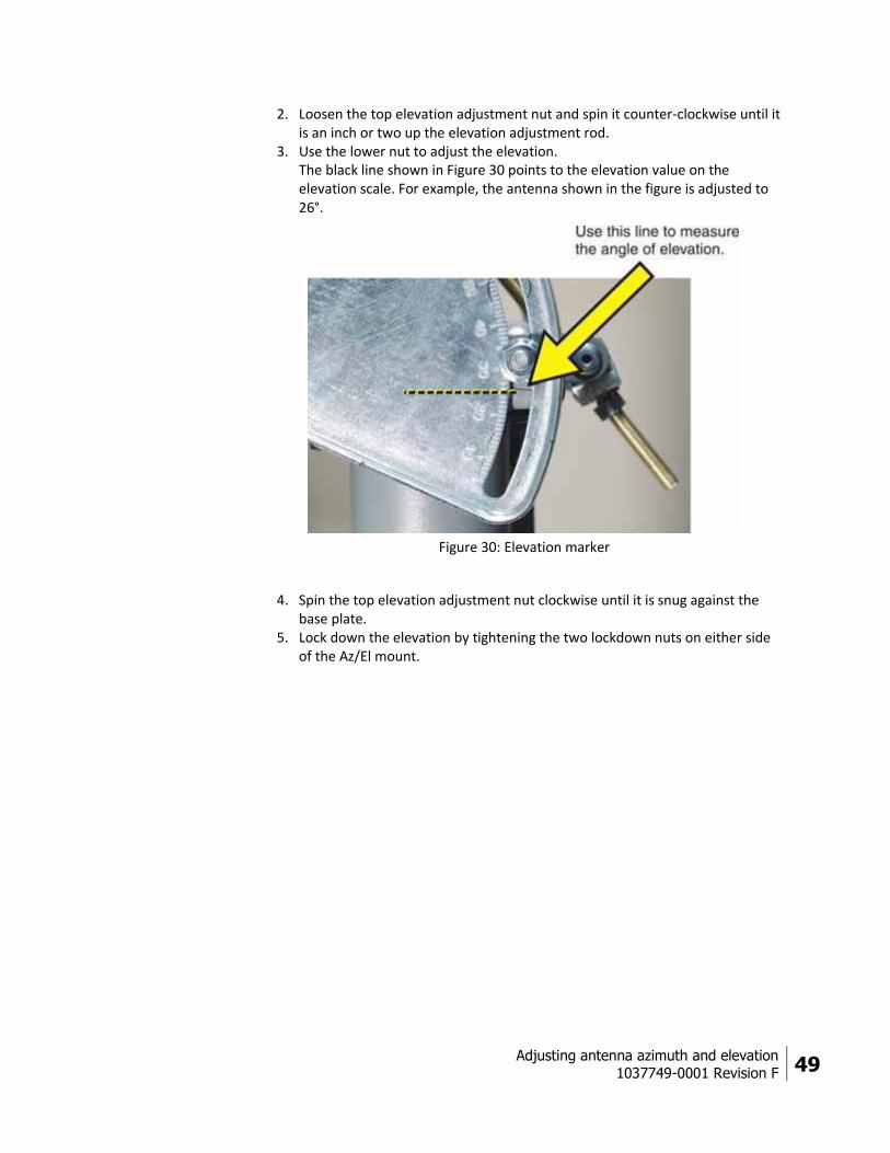
2. Loosen the top elevation adjustment nut and spin it counter-clockwise until it is an inch or two up the elevation adjustment rod.
3. Use the lower nut to adjust the elevation. The black line shown in Figure 30 points to the elevation value on the elevation scale. For example, the antenna shown in the figure is adjusted to 26°.
Figure 30: Elevation marker
4. Spin the top elevation adjustment nut clockwise until it is snug against the base plate.
5. Lock down the elevation by tightening the two lockdown nuts on either side of the Az/El mount.

50 Adjusting antenna azimuth and elevation
1037749-0001 Revision F
Adjusting azimuth
Figure 31 illustrates how you adjust antenna azimuth by moving the antenna horizontally, from side to side.
Figure 31: Adjusting antenna azimuth
Adjusting antenna azimuth and elevation
1037749-0001 Revision F 51
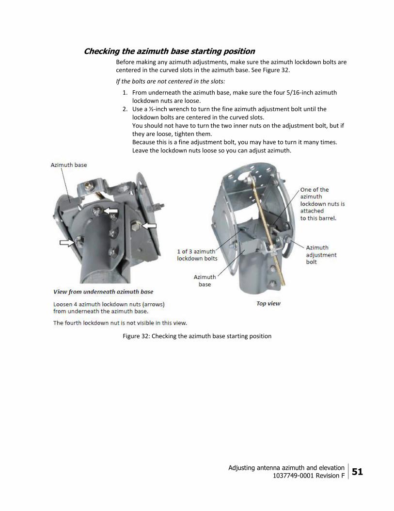
Checking the azimuth base starting position
Before making any azimuth adjustments, make sure the azimuth lockdown bolts are centered in the curved slots in the azimuth base. See Figure 32.
If the bolts are not centered in the slots:
1. From underneath the azimuth base, make sure the four 5/16-inch azimuth lockdown nuts are loose.
2. Use a ½-inch wrench to turn the fine azimuth adjustment bolt until the lockdown bolts are centered in the curved slots. You should not have to turn the two inner nuts on the adjustment bolt, but if they are loose, tighten them. Because this is a fine adjustment bolt, you may have to turn it many times. Leave the lockdown nuts loose so you can adjust azimuth.
Figure 32: Checking the azimuth base starting position
52 Adjusting antenna azimuth and elevation
1037749-0001 Revision F
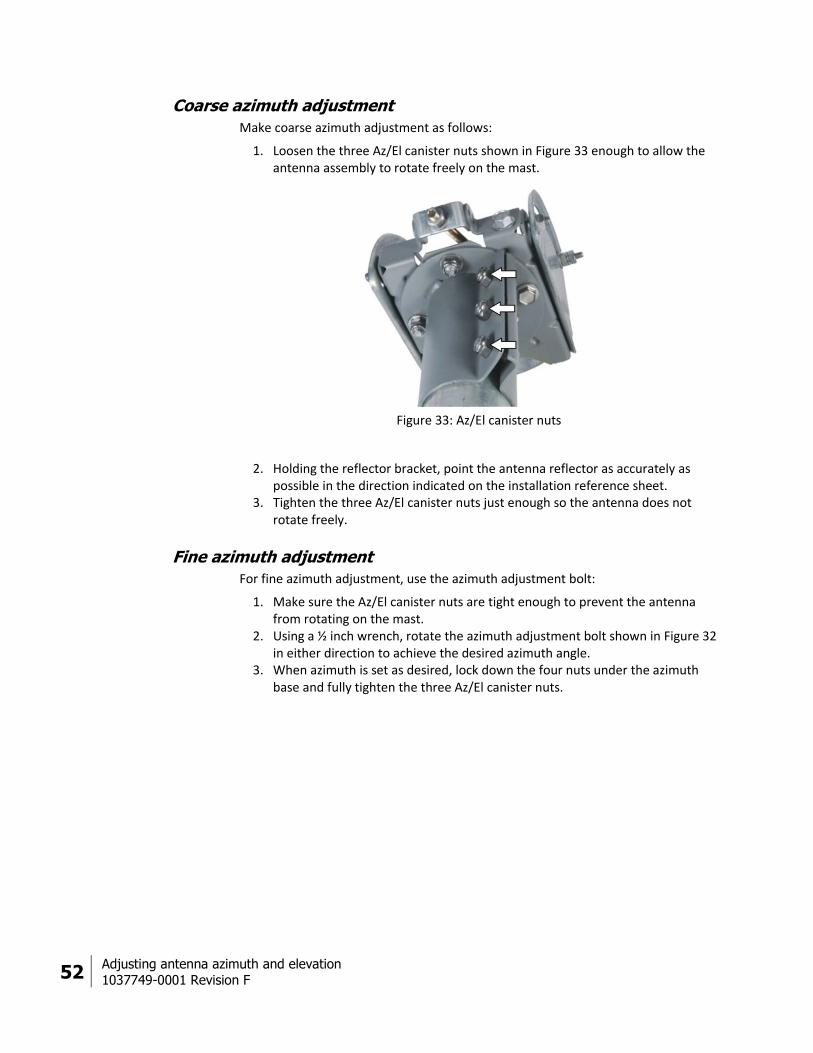
Coarse azimuth adjustment
Make coarse azimuth adjustment as follows:
1. Loosen the three Az/El canister nuts shown in Figure 33 enough to allow the antenna assembly to rotate freely on the mast.
Figure 33: Az/El canister nuts
2. Holding the reflector bracket, point the antenna reflector as accurately as possible in the direction indicated on the installation reference sheet.
3. Tighten the three Az/El canister nuts just enough so the antenna does not rotate freely.
Fine azimuth adjustment
For fine azimuth adjustment, use the azimuth adjustment bolt:
1. Make sure the Az/El canister nuts are tight enough to prevent the antenna from rotating on the mast.
2. Using a ½ inch wrench, rotate the azimuth adjustment bolt shown in Figure 32 in either direction to achieve the desired azimuth angle.
3. When azimuth is set as desired, lock down the four nuts under the azimuth base and fully tighten the three Az/El canister nuts.
Adjusting antenna azimuth and elevation
1037749-0001 Revision F 53
Final steps
After the antenna is pointed, complete the following steps before leaving the installation site.
Remove the pointing tool
Remove the DiSEqC antenna pointing tool (DAPT) (if used):
1. Disconnect the DAPT. 2. Reconnect the receive cable to the radio.
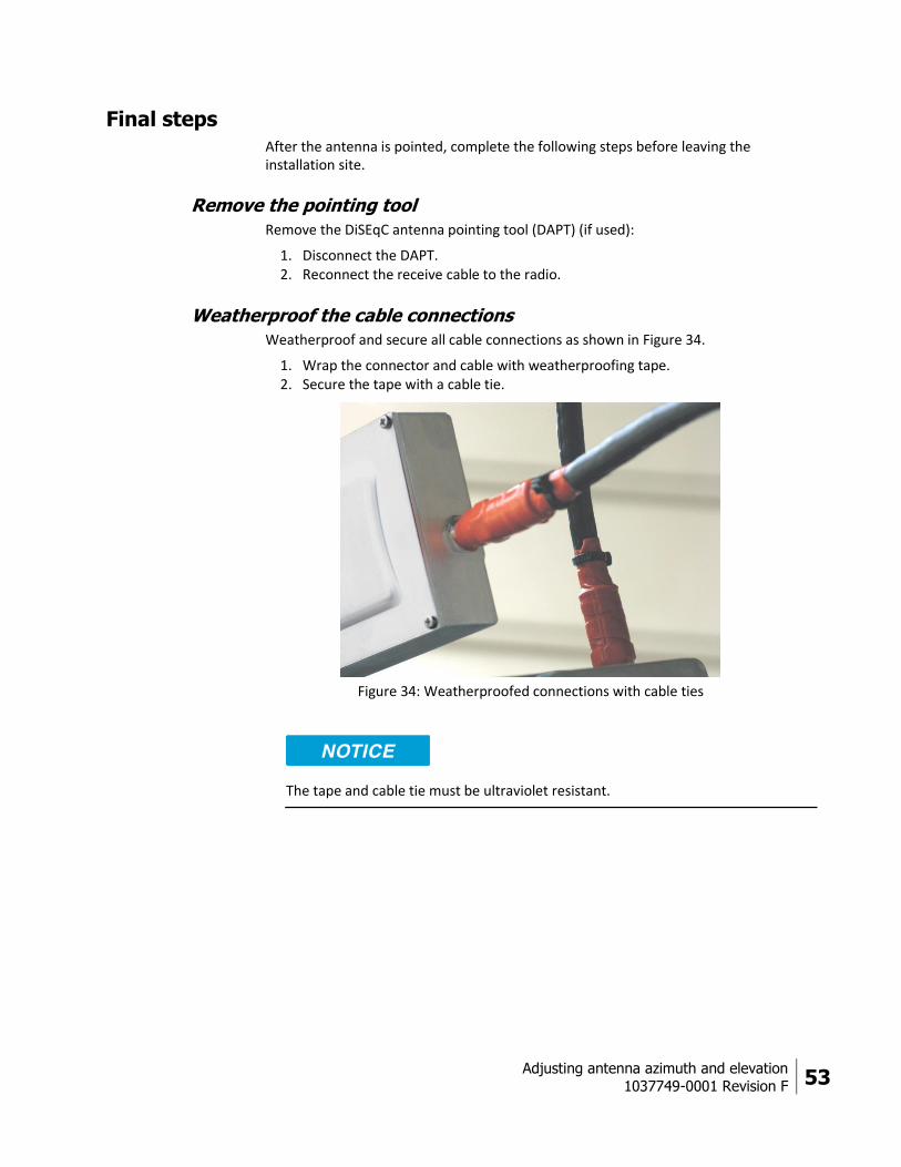
Weatherproof the cable connections
Weatherproof and secure all cable connections as shown in Figure 34.
1. Wrap the connector and cable with weatherproofing tape. 2. Secure the tape with a cable tie.
Figure 34: Weatherproofed connections with cable ties
The tape and cable tie must be ultraviolet resistant.

54 Adjusting antenna azimuth and elevation
1037749-0001 Revision F
Check for safety labels and signs
Make sure the required safety labels and/or signs are present:
Make sure a Radiation Hazard Caution label is present, legible, and visible on the feed support arm and on the rear of the antenna reflector.
If the antenna is enclosed by a fence, make sure a Radiation Hazard Caution sign is present, legible, and visible on the entrance gate.
If the antenna is installed on a roof with a permanently mounted access ladder, make sure a Radiation Hazard Caution sign is present, legible, and visible on or near the ladder.
Acronyms and abbreviations
1037749-0001 Revision F 55
Acronyms and abbreviations A
Az/El – Azimuth/elevation
D
DAPT – DiSEqC antenna pointing tool
F
FSB – Field service bulletin
ft – Foot
ft-lb – Foot-pound
G
GPS – Global positioning system
H
hr – Hour
I
IDU – Indoor unit
IFL – Intra-facility link
inch-lb – Inch-pound
L
LHCP – Left-hand circular polarization
LNB – Low noise block converter
LOS – Line of sight
M
m – Meter
N
NEC – National Electrical Code
NOCC – Network Operations Control Center
R
RHCP – Right-hand circular polarization
Rx – Receive
T
TRIA – Transmit/receive isolation assembly
Tx – Transmit


Index 1037749-0001 Revision F 57
Index A
Adjusting
azimuth 50
elevation 48
polarization 33
tilt 27
Antenna
kit components 17
mount installation 14
Az/El mount assembly
description 18
mounting to mast 39
Azimuth
adjusting 50
fine adjustment bolt 52
C
Cable connector locations 44
Cables
approved types 15, 41
connecting to radio assembly 44
maximum length 15
receive cable 45
routing at the antenna 42
service loops 43
transmit cable 43
Clamps, polarizer 34, 37
description 21
Connectors, cable and ground 45
E
Elevation, adjusting 48
F
Feed horn
description 21
installing 36
Feed support arm
description 20
installing 30
Final steps 53
G
Grounding 45
H
Hardware parts list 22
I
IDU, installing 15
IFL 12, 41
Installation
related tasks 14
Installation site, determining 14
Installation, summary of steps 13
Installing
antenna mount 14
Az/El mount assembly 40
feed horn 36
feed support arm 30
final steps 53
IDU 15
radio assembly 31
reflector 28
reflector bracket 27

58 Index
1037749-0001 Revision F
tilt plate 27
L
Leveling the mast 39
P
Parts list 22
Pointing values 25
Polarization setting 33
Polarizer 33
Polarizer clamps 34, 37
description 21
R
Radio assembly
connecting cables 44
description 20
installing 31
Receive cable
connecting to the LNB 45
routing 43
Reflector
description 19
installing 28
Reflector bracket
description 19
installing 27
S
Safety labels and/or signs 54
Setting tilt 28
Site survey, conducting 13
Summary of installation steps 13
T
Tasks related to installation 14
Tilt plate, installing 27
Tilt, setting 28
Tool list 23
Torque values (table) 26
Transmit cable
connecting 44
routing 43
Transmitter, radio 20
connecting cables 44


![Design of Ionofree Micro Strip Quad Helix Antenna for ... · antenna, bifilar helices antenna, microstrip antenna, quadrafilar helix antenna. ... Helical antenna [1],[2] is broadband](https://img.dokumen.tips/doc/110x75/5b9506e809d3f2ea5c8b5a04/design-of-ionofree-micro-strip-quad-helix-antenna-for-antenna-bifilar-helices.jpg)


