Embed Size (px)
Citation preview

070 Series ANSI Switchboard Meters
30
This high quality range of Switchboard instruments complies with the Americanspecification ANSI-C39.1 (1981) accuracy class 1. Available in 41/2" and 83/4" case sizes,their rugged design characteristics suit the most demanding of environmentalapplications. This extensive range of analogue and digital/analogue meters utilise ahigh shock oil dampened movement, and provide 1% accuracy for all RMS AC andDC ranges. The range offers various customised options and features.
Description 070 series offers two case sizes, 41/2" (Models 075, 077 & 078) and 83/4" (Model 079).Model 078 is high shock hermetically sealed and all models have heavy gaugepressed steel cases. Mounting is by four integral studs. Models 075 & 077 are a one piece flame retardant polycarbonate moulding with amatt black finished bezel area, and a specially contoured window to minimisereflection from adjacent light sources. Model 079 has a black pressed steel bezel witha toughened glass window, and Model 078 has a die-cast bezel and a projectingmoulded toughened glass window, which incorporates a gas tight zero adjuster. Scales are 240° moving iron and 250° moving coil with parallax error-free platformdials. Standard dials are matt white with black printed scales and bar knife-edgepointers. Black dials with white or yellow scales and pointers are also available.General options include supplementary red pointer (075 & 077), slave pointer,calibration for non standard ambient temperatures, special scales, trimpotentiometers, and Illuminated dials with white or red light sources.
Specification Performance: ANSI C39.1 (1981)Accuracy: Class 1Terminals: 10-32 UNF terminals (M5 screw clamp terminal for
Model 075) Dielectric Voltage: Withstand test 2.3kV for 1 minuteResponse Time: Approximately 2.5 seconds to full scale (077 and 078)
and 3.5 seconds (079)Overshoot: 33% maximumStandard Calibration: 23°C Operating Temperature: 0°C to +40°C. Model 078: -40°C to +70°C.Storage Temperature: -10°C to +50°CExtreme Temp Range: -20°C -to +65°CEnclosure Integrity: Models 075/077/079 to IP54(NEMA 3S) splash proof
IP55 (NEMA 4) hoseproof is an optional extraModel 078 to IP67 (NEMA 6 & 6P)
Fixing on Panel: 4 integral 1/4 -28 UNF fixing studsApprovals: EMC and LVD, UL, CSA, ABS and ISSep Approvals
DimensionsModel Panel Cut-out Rear
View
Dia A B C D E F G
075 103 86 43 110 17 - 30 101077 103 86 43 110 17 - 30 101078 103 86 43 110 17 - 30 101079 229 86 43 229 17 - 30 101
Dimension E varies with measured parameter - see product code table overleaf.
1 – 4 Fixing holes Ø 8mm. 2 – 1/4-28 UNF fixing studs. 3 – 10-32 UNF Terminals (M5screw clamp terminal on model 075).
Features
Rugged Hi-Q taut-band suspension
Accuracy class 1
JIS dimensioned product availableon request
Benefits
Meets all the requirements of ANSI-C39.1 (1981)
Parallax error-free platform dials
Bump, Shock and vibration proof
Customised options and features
Applications
Switchgear
Distribution systems
Generator sets
Control panels
Energy management
Building management
Utility power monitoring
Process control
Motor control
Approvals
UL approvals file No: E87815
CSA approvals file No: LR99712-1
ABS American Bureau of Shippingapprovals 93-LD 17806-X
ISSeP Institute Scientifique de ServicePublic approvals 97D.101.226x

070 Series ANSI Switchboard Meters
31
Product CodesCase Code
Type of Instrument Ranges 075 077 078 079 Product Code
A.C. Ammeter Moving iron 0.5-10A 56 56 - - 075/077-08AA.C. Ammeter Moving iron 0.5-10A - - 86 86 078/079-08AA.C. Ammeter Moving iron 10.1-30A - 86 86 86 077/078/079-08ASlave Pointer Ammeter 1 or 5A 86 077-08D6 x overload A.C. Ammeter 5/30A - 30/180A - 86 86 86 077/078/079-086A.C Voltmeter Moving iron 30-800V - 86 86 86 077/078/079-08VA.C. Rectified Ammeter 1-30A 56 56 86 56 075/077/078/079-05BA.C. Rectified Voltmeter 30-800V 56 56 86 56 075/077/078/079-05WA.C. Voltmeter expanded scale 110-130V - 86 86 86 077/078/079-05YA.C. RMS Ammeter 1-30A 56 56 86 56 075/077/078/079-05FA.C. RMS Voltmeter 150-750V 56 56 86 56 075/077/078/079-05GSlave Pointer Voltmeter 50-300V 86 077-05XElapsed time meter (99999.99) 50 or 60Hz / 100-440V* and D.C. - 56 56 - 077/078-155/156/077-151Frequency meter 50 or 60 or
400Hz/100-440V** 86 86 86 86 075/077/078/079-41LA.C. Wattmeter or Varmeter 0.2-10A/100-440V* - 132 132 132 077/078/079-21 or 31360˚ Rotary Power factor meter 0.2-10A/100-600V - 132 132 132 077/078/079-13360˚ Rotary synchroscope 100/125V, 200/250, 380/450*** - 132 132 132 077/078/079-14LED Synchroscope only 63.5-480V**** - 86 - - 077-14ALED Synchroscope & Synchro Check Relay 63.5-480V**** - 86 - - 077-14A.C. Meter relay A.C.6V-500V, - 86 - - 077-30
100µA-1A, 5A via C.T. (see Meter Relay section)Phase sequence indicator 100-150, 151-300, 301-500V - 56 - - 077-12PMaximum demand Indicator 1 or 5A - 86 - - 077-16Tap position indicator 1-18 steps. 400Ω - 86 - - 077-45PTransducer operated indicator 1, 5, 10, 20, or 4/20mA 56 56 56 56 075/077/078/079-05D.C. Ammeter Moving Coil 200µA - 30A 56 56 56 56 075/077/078/079-05AD.C. Voltmeter Moving Coil 50mV-600V 56 56 56 56 075/077/078/079-05VD.C. Meter relay 100mV-500V, 10µA-15A - 86 - - 077-30
(see Meter Relay section)Temperature Indicator RTD - 86 86 86 077/078/079-45RTemperature Indicator Thermocouple - 86 86 86 077/078/079-45T240° Phase Angle 1 or 5A, 100-400V/Power Factor 50, 60 or 400Hz - 132 132 132 077/078/079-42Watt/hour Indicators:
Watt/hour indicator 1 or 5A / 69-277V**** - 132 - - 077-KHTransducer operated 1, 5, 10, 20, or 4/20mA - 132 132 - 077-KHAnalogue/LED Digital indicators
A.C. Ammeter 1mA - 10A - 86 - - 077-DIBA.C. Voltmeter 200mV - 600V - 86 - - 077-DIWA.C. Wattmeter 69V/5A, 120V/5A, 50 or 60Hz - 86 - - 077-DWA.C. Varmeter 120V/5A, 208V/5A, 50 or 60Hz - 86 - - 077-DXPhase Angle meter 69V/5A, 120V/5A, 50 or 60Hz - 86 - - 077-DP Frequency meter 110/130V, 50 or 60Hz - 86 - - 077-DZD.C. Ammeter 1mA - 1A - 86 - - 077-DIAD.C. Voltmeter 20mV - 600V - 86 - - 077-DIVTransducer Indicator D.C. Milliamps - 86 - - 077-DITTachometer A.C. or D.C. rated - 86 - - 077-DI2
* 100-440V = (100/125, 200/250, 380/440)** 100-440V = (100/125,200/250, 380/440). Frequencies 45/55,55/65,45/65, 47/53, 57/63, 360/440.*** Using transformer box 855-954**** Nominal voltage to be specified
For specification and connection diagrams, please refer to equivalent models in 240 Series DIN Panel Meter section. Replace 244 with 077 etc., e.g. 244-210 becomes 077-210.

070 Series ANSI Switchboard Meters
32
A.C. & D.C. Ammeters, Voltmetersand Frequency MetersThis range of self contained Hi-Q taut band moving coil meters feature with 250°linear scale and oil dampened mechanisms for superior performance in highvibration situations. AC instruments are available with true RMS converting circuit or RMS compensated rectifier. Some types of frequency meters can be damaged bytransient supply voltage spikes. Crompton 077-41 frequency meters can withstand,without damage, 10 successive applications of transient spikes of 1250 volts. The range offers UL and CSA approvals. JIS dimensioned products are available on request.
Specification – GeneralManufactured in accordance with American National Standards ANSI C39.1, 1981
Accuracy: ±1% full scale at 23°C (73°F)Scale Arc: 250° full scale deflectionScale Length: 077 & 078: 175.2 mm (6.9")
079: 353 mm (13.9")Scale Plate: 2 piece, platform typeResponse Time: 077 & 078: Approximately 2.5 seconds to full scale
079: Approximately 3.5 seconds to full scaleOperating Temperature: 0 to 40°C (32 to 104°F)Storage Temperature: -10 to +50°C (14 to 122°F)Extreme Temp Range: -20° to +65°C (-4° to +149°F)Terminals: Standard 10-32 UNF stud Optional M5 screw clampPosition of Use: Vertical (scale)Dielectric Withstand: 2300V A.C. for 1 minute between electrical circuit
and caseOvershoot: 33% maximumEnclosure Code: 077 & 079: IP54, optional IP55
078: IP67Approvals: EMC and LVD. UL recognised File No: E87815.
CSA recognised File No: LR99712-1
Specification – Ammeters and VoltmetersOverload Rating: A.C. Ammeters - 2 x continuous, 50 x for 1 second
A.C. Voltmeters and frequency meters - 1.2 x continuousD.C. Ammeters - 2 x continuous 10 x for 1 secondD.C. Voltmeters - 1.2 x continuous
Frequency Range: A.C. calibration 60Hz ±20%
Specification – Frequency MetersResponse Time: 3 seconds maximumExternal Temperature 0.6 times accuracy maximum with ±10°C Influence: from reference temperatureExternal Field Influence: 2.0 times accuracy maximum with 0.5mT fieldAcceptable input Up to 30% distortionHarmonic Content:
Maximum Frequency Center Scale Error In
Hz Hz Hz
45-55 50 0.1546-54 50 0.1545-65 55 0.2550-70 60 0.2555-65 60 0.1556-64 60 0.1558-62 60 0.08
350-450 400 1.30360-440 400 1.25380-420 400 0.80

070 Series ANSI Switchboard Meters
33
Moving Iron A.C. Ammeters
Product Codes – Self Contained 40/70Hz (Accuracy ±1%, 60Hz)***41⁄2" Square Flange 83⁄4" Square Flange
Rating Scaling* Standard Case Sealed Case Hi-Shock Standard Case
Catalogue No. Catalogue No. Catalogue No.
1A 0-1A •/+077-08AA-LALA-C6 078-08AJ-LALA-C6 •079-08AA-LALA-C61.5A 0-1.5A •/+077-08AA-LCLC-C6 078-08AJ-LCLC-C6 •079-08AA-LCLC-C62A 0-2A •/+077-08AA-LELE-C6 078-08AJ-LELE-C6 •079-08AA-LELE-C63A 0-3A •/+077-08AA-LJLJ-C6 078-08AJ-LJLJ-C6 •079-08AA-LJLJ-C65A 0-5A •/+077-08AA-LSLS-C6 078-08AJ-LSLS-C6 •079-08AA-LSLS-C6
7.5A 0-7.5A •/+077-08AA-MFMF-C6 078-08AJ-MFMF-C6 •079-08AA-MFMF-C610A 0-10A •/+077-08AA-MTMT-C6 078-08AJ-MTMT-C6 •079-08AA-MTMT-C615A 0-15A •/+077-08AA-NDND-C6 078-08AJ-NDND-C6 •079-08AA-NDND-C620A 0-20A •/+077-08AA-NGNG-C6 078-08AJ-NGNG-C6 •079-08AA-NGNG-C630A 0-30A •/+077-08AA-NLNL-C6 078-08AJ-NLNL-C6 •079-08AA-NLNL-C6
Product Codes – Transformer Rated 40/70Hz - Burden 0.3VA***5 A 0-10A •/+077-08AA-LSMT-C6 078-08AJ-LSMT-C6 •079-08AA-LSMT-C65 A 0-15A •/+077-08AA-LSND-C6 078-08AJ-LSND-C6 •079-08AA-LSND-C65 A 0-20A •/+077-08AA-LSNG-C6 078-08AJ-LSNG-C6 •079-08AA-LSNG-C65 A 0-25A •/+077-08AA-LSNJ-C6 078-08AJ-LSNJ-C6 •079-08AA-LSNJ-C65 A 0-30A •/+077-08AA-LSNL-C6 078-08AJ-LSNL-C6 •079-08AA-LSNL-C65 A 0-40A •/+077-08AA-LSNP-C6 078-08AJ-LSNP-C6 •079-08AA-LSNP-C65 A 0-50A •/+077-08AA-LSNT-C6 078-08AJ-LSNT-C6 •079-08AA-LSNT-C65 A 0-75A •/+077-08AA-LSPB-C6 078-08AJ-LSPB-C6 •079-08AA-LSPB-C65 A 0-100A •/+077-08AA-LSPK-C6 078-08AJ-LSPK-C6 •079-08AA-LSPK-C65 A 0-150A •/+077-08AA-LSPZ-C6 078-08AJ-LSPZ-C6 •079-08AA-LSPZ-C65 A 0-200A •/+077-08AA-LSRL-C6 078-08AJ-LSRL-C6 •079-08AA-LSRL-C65 A 0-250A •/+077-08AA-LSRS-C6 078-08AJ-LSRS-C6 •079-08AA-LSRS-C65 A 0-300A •/+077-08AA-LSRX-C6 078-08AJ-LSRX-C6 •079-08AA-LSRX-C65 A 0-400A •/+077-08AA-LSSC-C6 078-08AJ-LSSC-C6 •079-08AA-LSSC-C65 A 0-500A •/+077-08AA-LSSF-C6 078-08AJ-LSSF-C6 •079-08AA-LSSF-C65 A 0-600A •/+077-08AA-LSSJ-C6 078-08AJ-LSSJ-C6 •079-08AA-LSSJ-C65 A 0-800A •/+077-08AA-LSSN-C6 078-08AJ-LSSN-C6 •079-08AA-LSSN-C65 A 0-1000A •/+077-08AA-LSSS-C6 078-08AJ-LSSS-C6 •079-08AA-LSSS-C65 A 0-1200A •/+077-08AA-LSSU-C6 078-08AJ-LSSU-C6 •079-08AA-LSSU-C65 A 0-1500A •/+077-08AA-LSTC-C6 078-08AJ-LSTC-C6 •079-08AA-LSTC-C65 A 0-1600A •/+077-08AA-LSTE-C6 078-08AJ-LSTE-C6 •079-08AA-LSTE-C65 A 0-2000A •/+077-08AA-LSTM-C6 078-08AJ-LSTM-C6 •079-08AA-LSTM-C65 A 0-2500A •/+077-08AA-LSTU-C6 078-08AJ-LSTU-C6 •079-08AA-LSTU-C65 A 0-3000A •/+077-08AA-LSUA-C6 078-08AJ-LSUA-C6 •079-08AA-LSUA-C65 A 0-4000A •/+077-08AA-LSUE-C6 078-08AJ-LSUE-C6 •079-08AA-LSUE-C65 A 0-5000A •/+077-08AA-LSUJ-C6 078-08AJ-LSUJ-C6 •079-08AA-LSUJ-C65 A 0-6000A •/+077-08AA-LSUP-C6 078-08AJ-LSUP-C6 •079-08AA-LSUP-C65 A 0-7000A •/+077-08AA-LSUS-C6 078-08AJ-LSUS-C6 •079-08AA-LSUS-C65 A 0-8000A •/+077-08AA-LSUW-C6 078-08AJ-LSUW-C6 •079-08AA-LSUW-C6
Product Code – A.C. Overload Ammeters - True RMS Reading***Self contained 40/70Hz (Accuracy ±1%)
5/30A TO SUIT 077-086A-LS**-C6 078-086J-LS**-C6 079-086A-LS**-C6077 moving iron ammeters available as listed above
Rated 5A for standard C.T’s with 6 x full scale. * Other scales are availableOverload portion of the scale is not subject to ** Specify scale requiredthe accuracy guarantee. *** Case types 077/078/079 use 10-32 • UL recognised File # E87815 UNF terminals. For M5 screw clamp+ CSA Approved File # LR52592 terminals stipulate case type 075
A.C. Overload Ammeters

070 Series ANSI Switchboard Meters
34
Moving Iron A.C. Voltmeters
Product Codes – Self Contained 60Hz ±20% (Accuracy ±1%)***41⁄2" Square Flange 83⁄4" Square Flange
Rating Scaling* Standard Case Sealed Case Hi-Shock Standard Case
Catalogue No. Catalogue No. Catalogue No.
150V 0-150V •/+077-08VA-PZPZ-C6 078-08VJ-PZPZ-C6 •079-08VA-PZPZ-C6250V 0-250V •/+077-08VA-RSRS-C6 078-08VJ-RSRS-C6 •079-08VA-RSRS-C6300V 0-300V •/+077-08VA-RXRX-C6 078-08VJ-RXRX-C6 •079-08VA-RXRX-C6500V 0-500V •/+077-08VA-SFSF-C6 078-08VJ-SFSF-C6 •079-08VA-SFSF-C6600V 0-600V •/+077-08VA-SJSJ-C6 078-08VJ-SJSJ-C6 •079-08VA-SJSJ-C6750V 0-750V 077-08VA-SMSM-C6 078-08VJ-SMSM-C6 079-08VA-SMSM-C6
Product Codes – Transfomer Rated 50/60HZ (Accuracy ±1%) 0.8VA@150V***
150V 0-300V •/+077-08VA-PZRX-C6 078-08VJ-PZRX-C6 •079-08VA-PZRX-C6150V 0-600V •/+077-08VA-PZSJ-C6 078-08VJ-PZSJ-C6 •079-08VA-PZSJ-C6150V 0-750V •/+077-08VA-PZSM-C6 078-08VJ-PZSM-C6 •079-08VA-PZSM-C6150V 0-3000V •/+077-08VA-PZUA-C6 078-08VJ-PZUA-C6 •079-08VA-PZUA-C6150V 0-5250V •/+077-08VA-PZUL-C6 078-08VJ-PZUL-C6 •079-08VA-PZUL-C6150V 0-6000V •/+077-08VA-PZUP-C6 078-08VJ-PZUP-C6 •079-08VA-PZUP-C6150V 0-9000V •/+077-08VA-PZUY-C6 078-08VJ-PZUY-C6 •079-08VA-PZUY-C6150V 0-15KV •/+077-08VA-PZWC-C6 078-08VJ-PZWC-C6 •079-08VA-PZWC-C6150V 0-18KV •/+077-08VA-PZWD-C6 078-08VJ-PZWD-C6 •079-08VA-PZWD-C6150V 0-45KV •/+077-08VA-PZWJ-C6 078-08VJ-PZWJ-C6 •079-08VA-PZWJ-C6250V 0-600V •/+077-08VA-RSSJ-C6 078-08VJ-RSSJ-C6 •079-08VA-RSSJ-C6
• UL recognised File # E87815 * Other scales are available+ CSA Approved File # LR52592 *** Case types 077/078/079 use 10-32
UNF terminals. For M5 screw clamp terminals stipulate case type 075
A.C. Voltmeter
070 Series ANSI Switchboard Meters
35
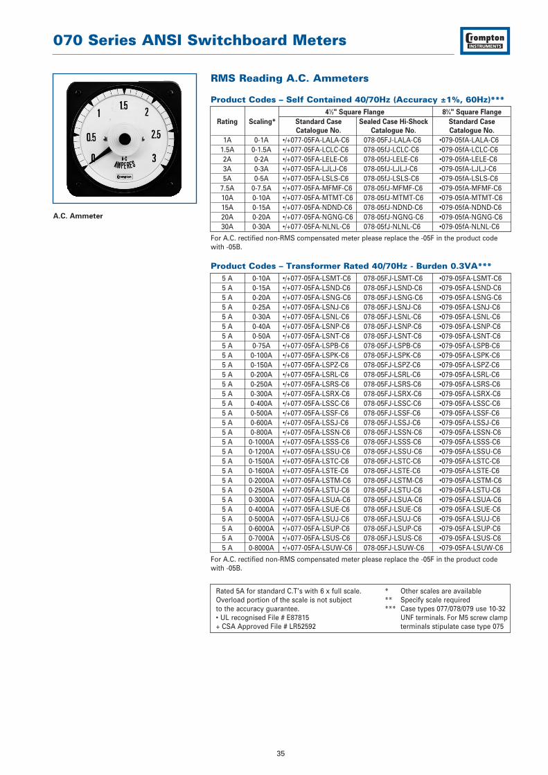
RMS Reading A.C. Ammeters
Product Codes – Self Contained 40/70Hz (Accuracy ±1%, 60Hz)***41⁄2" Square Flange 83⁄4" Square Flange
Rating Scaling* Standard Case Sealed Case Hi-Shock Standard Case
Catalogue No. Catalogue No. Catalogue No.
1A 0-1A •/+077-05FA-LALA-C6 078-05FJ-LALA-C6 •079-05fA-LALA-C61.5A 0-1.5A •/+077-05FA-LCLC-C6 078-05fJ-LCLC-C6 •079-05fA-LCLC-C62A 0-2A •/+077-05FA-LELE-C6 078-05fJ-LELE-C6 •079-05fA-LELE-C63A 0-3A •/+077-05FA-LJLJ-C6 078-05fJ-LJLJ-C6 •079-05fA-LJLJ-C65A 0-5A •/+077-05FA-LSLS-C6 078-05fJ-LSLS-C6 •079-05fA-LSLS-C6
7.5A 0-7.5A •/+077-05FA-MFMF-C6 078-05fJ-MFMF-C6 •079-05fA-MFMF-C610A 0-10A •/+077-05FA-MTMT-C6 078-05fJ-MTMT-C6 •079-05fA-MTMT-C615A 0-15A •/+077-05FA-NDND-C6 078-05fJ-NDND-C6 •079-05fA-NDND-C620A 0-20A •/+077-05FA-NGNG-C6 078-05fJ-NGNG-C6 •079-05fA-NGNG-C630A 0-30A •/+077-05FA-NLNL-C6 078-05fJ-NLNL-C6 •079-05fA-NLNL-C6
For A.C. rectified non-RMS compensated meter please replace the -05F in the product codewith -05B.
Product Codes – Transformer Rated 40/70Hz - Burden 0.3VA***5 A 0-10A •/+077-05FA-LSMT-C6 078-05FJ-LSMT-C6 •079-05FA-LSMT-C65 A 0-15A •/+077-05FA-LSND-C6 078-05FJ-LSND-C6 •079-05FA-LSND-C65 A 0-20A •/+077-05FA-LSNG-C6 078-05FJ-LSNG-C6 •079-05FA-LSNG-C65 A 0-25A •/+077-05FA-LSNJ-C6 078-05FJ-LSNJ-C6 •079-05FA-LSNJ-C65 A 0-30A •/+077-05FA-LSNL-C6 078-05FJ-LSNL-C6 •079-05FA-LSNL-C65 A 0-40A •/+077-05FA-LSNP-C6 078-05FJ-LSNP-C6 •079-05FA-LSNP-C65 A 0-50A •/+077-05FA-LSNT-C6 078-05FJ-LSNT-C6 •079-05FA-LSNT-C65 A 0-75A •/+077-05FA-LSPB-C6 078-05FJ-LSPB-C6 •079-05FA-LSPB-C65 A 0-100A •/+077-05FA-LSPK-C6 078-05FJ-LSPK-C6 •079-05FA-LSPK-C65 A 0-150A •/+077-05FA-LSPZ-C6 078-05FJ-LSPZ-C6 •079-05FA-LSPZ-C65 A 0-200A •/+077-05FA-LSRL-C6 078-05FJ-LSRL-C6 •079-05FA-LSRL-C65 A 0-250A •/+077-05FA-LSRS-C6 078-05FJ-LSRS-C6 •079-05FA-LSRS-C65 A 0-300A •/+077-05FA-LSRX-C6 078-05FJ-LSRX-C6 •079-05FA-LSRX-C65 A 0-400A •/+077-05FA-LSSC-C6 078-05FJ-LSSC-C6 •079-05FA-LSSC-C65 A 0-500A •/+077-05FA-LSSF-C6 078-05FJ-LSSF-C6 •079-05FA-LSSF-C65 A 0-600A •/+077-05FA-LSSJ-C6 078-05FJ-LSSJ-C6 •079-05FA-LSSJ-C65 A 0-800A •/+077-05FA-LSSN-C6 078-05FJ-LSSN-C6 •079-05FA-LSSN-C65 A 0-1000A •/+077-05FA-LSSS-C6 078-05FJ-LSSS-C6 •079-05FA-LSSS-C65 A 0-1200A •/+077-05FA-LSSU-C6 078-05FJ-LSSU-C6 •079-05FA-LSSU-C65 A 0-1500A •/+077-05FA-LSTC-C6 078-05FJ-LSTC-C6 •079-05FA-LSTC-C65 A 0-1600A •/+077-05FA-LSTE-C6 078-05FJ-LSTE-C6 •079-05FA-LSTE-C65 A 0-2000A •/+077-05FA-LSTM-C6 078-05FJ-LSTM-C6 •079-05FA-LSTM-C65 A 0-2500A •/+077-05FA-LSTU-C6 078-05FJ-LSTU-C6 •079-05FA-LSTU-C65 A 0-3000A •/+077-05FA-LSUA-C6 078-05FJ-LSUA-C6 •079-05FA-LSUA-C65 A 0-4000A •/+077-05FA-LSUE-C6 078-05FJ-LSUE-C6 •079-05FA-LSUE-C65 A 0-5000A •/+077-05FA-LSUJ-C6 078-05FJ-LSUJ-C6 •079-05FA-LSUJ-C65 A 0-6000A •/+077-05FA-LSUP-C6 078-05FJ-LSUP-C6 •079-05FA-LSUP-C65 A 0-7000A •/+077-05FA-LSUS-C6 078-05FJ-LSUS-C6 •079-05FA-LSUS-C65 A 0-8000A •/+077-05FA-LSUW-C6 078-05FJ-LSUW-C6 •079-05FA-LSUW-C6
For A.C. rectified non-RMS compensated meter please replace the -05F in the product codewith -05B.
Rated 5A for standard C.T’s with 6 x full scale. * Other scales are availableOverload portion of the scale is not subject ** Specify scale requiredto the accuracy guarantee. *** Case types 077/078/079 use 10-32 • UL recognised File # E87815 UNF terminals. For M5 screw clamp+ CSA Approved File # LR52592 terminals stipulate case type 075
A.C. Ammeter
070 Series ANSI Switchboard Meters
36
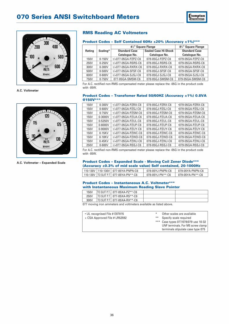
A.C. Voltmeter
RMS Reading AC Voltmeters
Product Codes – Self Contained 60Hz ±20% (Accuracy ±1%)***41⁄2" Square Flange 83⁄4" Square Flange
Rating Scaling* Standard Case Sealed Case Hi-Shock Standard Case
Catalogue No. Catalogue No. Catalogue No.
150V 0-150V •/+077-05GA-PZPZ-C6 078-05GJ-PZPZ-C6 •079-05GA-PZPZ-C6250V 0-250V •/+077-05GA-RSRS-C6 078-05GJ-RSRS-C6 •079-05GA-RSRS-C6300V 0-300V •/+077-05GA-RXRX-C6 078-05GJ-RXRX-C6 •079-05GA-RXRX-C6500V 0-500V •/+077-05GA-SFSF-C6 078-05GJ-SFSF-C6 •079-05GA-SFSF-C6600V 0-600V •/+077-05GA-SJSJ-C6 078-05GJ-SJSJ-C6 •079-05GA-SJSJ-C6750V 0-750V 077-05GA-SMSM-C6 078-05GJ-SMSM-C6 079-05GA-SMSM-C6
For A.C. rectified non-RMS compensated meter please replace the -05G in the product codewith -05W.
Product Codes – Transfomer Rated 50/60HZ (Accuracy ±1%) 0.8VA@150V***
150V 0-300V •/+077-05GA-PZRX-C6 078-05GJ-PZRX-C6 •079-05GA-PZRX-C6150V 0-600V •/+077-05GA-PZSJ-C6 078-05GJ-PZSJ-C6 •079-05GA-PZSJ-C6150V 0-750V •/+077-05GA-PZSM-C6 078-05GJ-PZSM-C6 •079-05GA-PZSM-C6150V 0-3000V •/+077-05GA-PZUA-C6 078-05GJ-PZUA-C6 •079-05GA-PZUA-C6150V 0-5250V •/+077-05GA-PZUL-C6 078-05GJ-PZUL-C6 •079-05GA-PZUL-C6150V 0-6000V •/+077-05GA-PZUP-C6 078-05GJ-PZUP-C6 •079-05GA-PZUP-C6150V 0-9000V •/+077-05GA-PZUY-C6 078-05GJ-PZUY-C6 •079-05GA-PZUY-C6150V 0-15KV •/+077-05GA-PZWC-C6 078-05GJ-PZWC-C6 •079-05GA-PZWC-C6150V 0-18KV •/+077-05GA-PZWD-C6 078-05GJ-PZWD-C6 •079-05GA-PZWD-C6150V 0-45KV •/+077-05GA-PZWJ-C6 078-05GJ-PZWJ-C6 •079-05GA-PZWJ-C6250V 0-600V •/+077-05GA-RSSJ-C6 078-05GJ-RSSJ-C6 •079-05GA-RSSJ-C6
For A.C. rectified non-RMS compensated meter please replace the -05G in the product codewith -05W.
Product Codes – Expanded Scale - Moving Coil Zener Diode***(Accuracy ±0.3% of mid scale value) Self contained, 20-1000Hz110-130V 110-130V 077-05YA-PNPN-C6 078-05YJ-PNPN-C6 079-05YA-PNPN-C6110-130V TO SUIT P.T 077-05YA-PN**-C6 078-05YJ-PN**-C6 079-05YA-PN**-C6
Product Codes – Instantaneous A.C. Voltmeter***with Instantaneous Maximum Reading Slave Pointer
150V TO SUIT P.T. 077-05XA-PZ**-C6250V TO SUIT P.T 077-05XA-RS**-C6300V TO SUIT P.T 077-05XA-RX**-C6
077 moving iron ammeters and voltmeters available as listed above.
• UL recognised File # E87815 * Other scales are available+ CSA Approved File # LR52592 ** Specify scale required
*** Case types 077/078/079 use 10-32 UNF terminals. For M5 screw clampterminals stipulate case type 075
A.C. Voltmeter – Expanded Scale

070 Series ANSI Switchboard Meters
37
D.C. Ammeter
Intrinsically Safe Milliammeters
(Accuracy ±1%)
ISSEP Certified
Rating Std Case
Catalogue No.
1mA D.C. 077-11AF-FA**5mA D.C. 077-11AF-FX**10mA D.C. 077-11AF-HA**20mA D.C. 077-11AF-HF**4/20mA D.C. 077-11RFHG**
** State scale marking as required
• UL recognised File # E87815+ CSA Approved File # LR52592Specify shunt lead resistance value if in excess of 0.05 OHMS for calibration purposes. D.C. shunt rated ammeters have thermistor circuit ambient temperaturecompensation.Separate shunt and shunt leads are not included.* Other scales are available** Specify scale required.*** Other mV ratings and scale
options available upon request.**** Case types 077/078/079 use
10-32 UNF terminals. For M5 screw clamp terminals stipulate case type 075.
D.C. Ammeters
Product Codes – Self Contained (Accuracy ±1%)****41⁄2" Square Flange 83⁄4" Square Flange
Rating Scaling* Standard Case Sealed Case Hi-Shock Standard Case
Catalogue No. Catalogue No. Catalogue No.
0-200µA 0-200µA •/+077-05AA-EAEA 078-05AJ-EAEA •079-05AA-EAEA0-300µA 0-300µA •/+077-05AA-EEEE 078-05AJ-EEEE •079-05AA-EEEE0-500µA 0-500µA •/+077-05AA-EMEM 078-05AJ-EMEM •079-05AA-EMEM0-800µA 0-800µA •/+077-05AA-EWEW 078-05AJ-EWEW •079-05AA-EWEW0-1mA 0-1mA •/+077-05AA-FAFA 078-05AJ-FAFA •079-05AA-FAFA0-2mA 0-2mA •/+077-05AA-FGFG 078-05AJ-FGFG •079-05AA-FGFG0-5mA 0-5mA •/+077-05AA-FXFX 078-05AJ-FXFX •079-05AA-FXFX0-10mA 0-10mA •/+077-05AA-HAHA 078-05AJ-HAHA •079-05AA-HAHA0-20mA 0-20mA •/+077-05AA-HFHF 078-05AJ-HFHF •079-05AA-HFHF0-30mA 0-30mA •/+077-05AA-HMHM 078-05AJ-HMHM •079-05AA-HMHM0-50mA 0-50mA •/+077-05AA-HXHY 078-05AJ-HXHY •079-05AA-HXHY0-100mA 0-100mA •/+077-05AA-JRJR 078-05AJ-JRJR •079-05AA-JRJR0-200mA 0-200mA •/+077-05AA-KAKA 078-05AJ-KAKA •079-05AA-KAKA0-300mA 0-300mA •/+077-05AA-KGKG 078-05AJ-KGKG •079-05AA-KGKG0-500mA 0-500mA •/+077-05AA-KMKM 078-05AJ-KMKM •079-05AA-KMKM0-800mA 0-800mA •/+077-05AA-KWKW 078-05AJ-KWKW •079-05AA-KWKW
0-1A 0-1A •/+077-05AA-LALA 078-05AJ-LALA •079-05AA-LALA0-5A 0-5A •/+077-05AA-LSLS 078-05AJ-LSLS •079-05AA-LSLS0-10A 0-10A •/+077-05AA-MTMT 078-05AJ-MTMT •079-05AA-MTMT0-15A 0-15A •/+077-05AA-NDND 078-05AJ-NDND •079-05AA-NDND0-20A 0-20A •/+077-05AA-NGNG 078-05AJ-NGNG •079-05AA-NGNG0-30A 0-30A •/+077-05AA-NLNL 078-05AJ-NLNL •079-05AA-NLNL
Product Codes – Milliammeters - Suppressed Zero, No zero set unless specified****1/5mA To Suit •/+077-05RA-GM** 078-05RJ-GM** •079-05RA-GM**4/20mA To Suit •/+077-05RA-HG** 078-05RJ-HG** •079-05RA-HG**10/50mA To Suit •/+077-05RA-HZ** 078-05RJ-HZ** •079-05RA-HZ**
Product Codes – Shunt Rated (Accuracy ±1%)****50mV (4mA) To suit •/+077-05AA-EY** 078-05AJ-EY** 079-05AA-EY**
50-0-50mV shunt •/+077-05CA-GB** 078-05CJ-GB** 079-05CA-GB**
100mV (4mA) rating •/+077-05AA-GB** 078-05AJ-GB** 079-05AA-GB**
100-0-100mV •/+077-05CA-GM** 078-05CJ-GM** 079-05CA-GM**
Product Codes – Zero Left For Use With 50mV Shunts And 0.05Ohm Shunt Leads*** & ****
50mV 0-15A •/+077-05AA-EYND 078-05AJ-EYND 079-05AA-EYND50mV 0-20A •/+077-05AA-EYNG 078-05AJ-EYNG 079-05AA-EYNG50mV 0-30A •/+077-05AA-EYNL 078-05AJ-EYNL 079-05AA-EYNL50mV 0-40A •/+077-05AA-EYNP 078-05AJ-EYNP 079-05AA-EYNP50mV 0-75A •/+077-05AA-EYPB 078-05AJ-EYPB 079-05AA-EYPB50mV 0-100A •/+077-05AA-EYPK 078-05AJ-EYPK 079-05AA-EYPK50mV 0-150A •/+077-05AA-EYPZ 078-05AJ-EYPZ 079-05AA-EYPZ50mV 0-200A •/+077-05AA-EYRL 078-05AJ-EYRL 079-05AA-EYRL50mV 0-300A •/+077-05AA-EYRX 078-05AJ-EYRX 079-05AA-EYRX50mV 0-400A •/+077-05AA-EYSC 078-05AJ-EYSC 079-05AA-EYSC50mV 0-500A •/+077-05AA-EYSF 078-05AJ-EYSF 079-05AA-EYSF50mV 0-750A •/+077-05AA-EYSM 078-05AJ-EYSM 079-05AA-EYSM50mV 0-1000A •/+077-05AA-EYSS 078-05AJ-EYSS 079-05AA-EYSS50mV 0-1200A •/+077-05AA-EYSU 078-05AJ-EYSU 079-05AA-EYSU50mV 0-1500A •/+077-05AA-EYTC 078-05AJ-EYTC 079-05AA-EYTC50mV 0-2000A •/+077-05AA-EYTM 078-05AJ-EYTM 079-05AA-EYTM50mV 0-3000A •/+077-05AA-EYUA 078-05AJ-EYUA 079-05AA-EYUA

070 Series ANSI Switchboard Meters
38
D.C. Voltmeter
Frequency Meter
D.C. Voltmeters
Product Codes – Sensitivity 1000 ohms / Volt (Accuracy ±1%)***41⁄2" Square Flange 83⁄4" Square Flange
Rating Scaling* Standard Case Sealed Case Hi-Shock Standard Case
Catalogue No. Catalogue No. Catalogue No.
50mV to 800V TO SUIT •/+077-05VA-** 078-05VJ-** 079-05VA-**0-15V 0-15V •/+077-05VA-NDND 078-05VJ-NDND 079-05VA-NDND0-30V 0-30V •/+077-05VA-NLNL 078-05VJ-NLNL 079-05VA-NLNL0-50V 0-50V •/+077-05VA-NTNT 078-05VJ-NTNT 079-05VA-NTNT0-75V 0-75V •/+077-05VA-PBPB 078-05VJ-PBPB 079-05VA-PBPB0-150V 0-150V •/+077-05VA-PZPZ 078-05VJ-PZPZ 079-05VA-PZPZ0-300V 0-300V •/+077-05VA-RXRX 078-05VJ-RXRX 079-05VA-RXRX0-400V 0-400V •/+077-05VA-SCSC 078-05VJ-SCSC 079-05VA-SCSC0-500V 0-500V •/+077-05VA-SFSF 078-05VJ-SFSF 079-05VA-SFSF0-600V 0-600V •/+077-05VA-SJSJ 078-05VJ-SJSJ 079-05VA-SJSJ0-750V 0-750V 077-05VA-SMSM 078-05VJ-SMSM 079-05VA-SMSM0-800V 0-800V 077-05VA-SNSN 078-05VJ-SNSN 079-05VA-SNSN
Product Codes – Zero Centre - Sensitivity 2000 Ohms / Volt(Accuracy ±1%)***150-0-150V 150-0-150V •/+077-05NA-RXRX 078-05NJ-RXRX 079-05NA-RXRX300-0-300V 300-0-300V •/+077-05NA-SJSJ 078-05NJ-SJSJ 079-05NA-SJSJ500-0-500V 500-0-500V •/+077-05NA-SSSS 078-05NJ-SSSS 079-05NA-SSSS600-0-600V 600-0-600V •/+077-05NA-SUSU 078-05NJ-SUSU 079-05NA-SUSU
Product Code – Suppressed Zero***1 - 5V TO SUIT •/+077-05S-LM 078-05S-LM •079-05S-LM
Frequency Meters
Product Code –120V Self Contained***41⁄2" Square Flange 83⁄4" Square Flange
Rating Scaling* Standard Case Sealed Case Hi-Shock Standard Case
Catalogue No. Catalogue No. Catalogue No.
50Hz+/-0.15 45-55Hz •/+077-41LA-PNAG-AG 078-41LJ-PNAG-AG •079-41LA-PNAG-AG50Hz+/-0.15 46-54Hz •/+077-41LA-PNAH-AH 078-41LJ-PNAH-AH •079-41LA-PNAH-AH50Hz+/-0.25 45-65Hz •/+077-41LA-PNAJ-AJ 078-41LJ-PNAJ-AJ •079-41LA-PNAJ-AJ60Hz+/-0.25 50-70Hz •/+077-41LA-PNAL-AL 078-41LJ-PNAL-AL •079-41LA-PNAL-AL60Hz+/-0.15 55-65Hz •/+077-41LA-PNAN-AN 078-41LJ-PNAN-AN •079-41LA-PNAN-AN60Hz+/-0.15 56-64Hz •/+077-41LA-PNAO-AO 078-41LJ-PNAO-AO •079-41LA-PNAO-AO60Hz+/-0.08 58-62Hz •/+077-41LA-PNAT-AG 078-41LJ-PNAG-AG •079-41LA-PNAG-AG400Hz+/-1.3 350-450Hz •/+077-41LA-PNBH-BH 078-41LJ-PNBH-BH •079-41LA-PNBH-BH400Hz+/-1.25 360-440Hz •/+077-41LA-PNBI-BI 078-41LJ-PNBI-BI •079-41LA-PNBI-BI400Hz+/- 0.8 380-420Hz •/+077-41LA-PNBK-BK 078-41LJ-PNBK-BK 079-41LA-PNBK-BK
Alternative voltage rating 200-250V use code * Other scales are available RN instead of PN ** Specify scale requiredAlternative voltage rating 380-480V use code *** Case types 077/078/079 use 10-32SE instead of PN UNF terminals. For M5 screw clamp• UL recognised File number E87815 terminals stipulate case type 075

070 Series ANSI Switchboard Meters
39
Thermal Maximum Demand Directly Heated Element TypeIndicates the maximum average ampere demand of a system. A red resettable slavepointer is driven upscale by the indicating pointer to show maximum average valueof current since the previous setting. 41/2" square flange.
SpecificationBurden: 3.5VA with limiting C.T., 2.5VA without limiting C.T.Time lag: 15 minutesAccuracy: 3% 50 or 60Hz
Product Codes5/6A with 20% overload and internal limiting C.T. •077-16EU-LS**
5A - without overload, with internal limiting C.T. •077-16EU-LS**- NO
Thermal / Instantaneous Maximum Demand Ammeter (MDA)Allows instantaneous values of current to be read independently of the thermalindicator. This meter combines a thermal movement, with a rugged shortscale ironvane indicator.
SpecificationBurden: 4VA with limiting C.T., 3VA without limiting C.T.Time Lag: 15 minsAccuracy: 3% MDA, 2% Iron Vane 50 or 60Hz
Product CodesThermal / Instantaneous MDA
5/6A with 20% overload scale and internal limiting C.T. •077-16FU-LS**
5A - without 20% overload scale, with internal limiting C.T. •077-16FU-LS** - NODual Range - Thermal Instantaneous
3/6A - with 20% overload scale •077-16FU-LK**2.5/5A - without 20% overload scale •077-16FU-LK** - NO6/12A with 20% overload scale and internal limiting C.T. •077-16FU-LV**5/10A - without 20% overload scale with internal limiting C.T. •077-16FU-LV** - NO
Instantaneous Maximum Demand Ammeter with SlavePointerDesigned to be compatible with other 41⁄2" switchboard meters. This instrumentenhances panel appearance and indicates maximum instantaneous values of loadcurrent. The meter incorporates a longscale high torque taut band iron vanemovement to drive the red slave pointer.
SpecificationBurden: 5VA, Accuracy -1% 50 or 60Hz
Product Code5A - without overload scale 077-08DA-LS**
** Specify scale required• UL recognised
A.C. Maximum Demand Ammeter
Thermal Instantaneous Maximum
Demand Ammeter
Instantaneous Maximum Demand
Ammeter

070 Series ANSI Switchboard Meters
40
A.C. Wattmeters & VarmetersThe Crompton 70 series of A.C. Wattmeters and Varmeters incorporate a DC movingcoil taut band indicator with the Crompton designed micro-circuit Watt transducerPCB to read power on single phase or three phase systems. Varmeters can besupplied with internal phase shifter or with external phase shifter if preferred. In theinterest of standardisation, preferred Wattmeter scale marking for common currentand voltage transformers are listed on the following pages. Instruments may besupplied with zero left or center zero scales at the same list price.
ScalingSince Wattmeter and Varmeter current circuits are frequently connected in series,they should have equal current carrying capacity. This means that to assure equalitythe sum of the left and right end-scale values of the Varmeters should be equal to orgreater than the full scale value of the Wattmeter (or the higher of the end-scalevalues if center or offset zero). Instruments 10,000 kilowatts and over are marked inmegawatts. Center zero or offset zero Watt and Varmeters are marked “IN” for leftdeflection and “OUT” for right deflection. Preferred scales may be calculated forWattmeters and varmeters not listed on the charts. Scale Watts must be one of thestandard full scale dial markings shown on the charts.
CalibrationFor full load value of Watts or Vars, assuming unity power factor:1ph 2 wire Watts = amps x volts3ph 3 wire Watts = amps x line to line volts x √33ph 4 wire Watts = amps x line to neutral volts x 3Minimum scale values are obtained by multiplying resultant Watts using aboveformula x 0.7 and selecting next highest standard scale.For maximum scale value multiply x 1.3 and select next lowest standard.If scale calculates to an exact listed value use it rather than the next higher orlower value. Note: When ordering Wattmeters and Varmeters specify C.T. ratio, V.T. ratio andrequired scale.
SpecificationBurden per element: Current circuit: 2VA
Voltage circuit: 1VAAccuracy Class: 1.0Ambient range: 0° to +60°C, (32° to 140°F) standard calibration 20°C (68°F)Ambient influence: 0.05% per 1°C maximumOverloads-current: 10 x rating for 5 seconds., 1.2 x continuouslyVoltage: 2 x rating for 5 seconds., 1.2 x continuouslyVoltage influence: Accuracy maintained, 80-110% rated voltagePower Factor influence: Accuracy maintained 0.1 lag to 0.1 leadEnclosure code: 077: IP54 optional IP55
078: IP67079: IP54 optional IP55
Response Time: 077,078: approximately 2.5 seconds079: approximately 3.5 seconds
Dielectric test: Live parts to case including panel 2600V RMS for 1 minute

070 Series ANSI Switchboard Meters
41
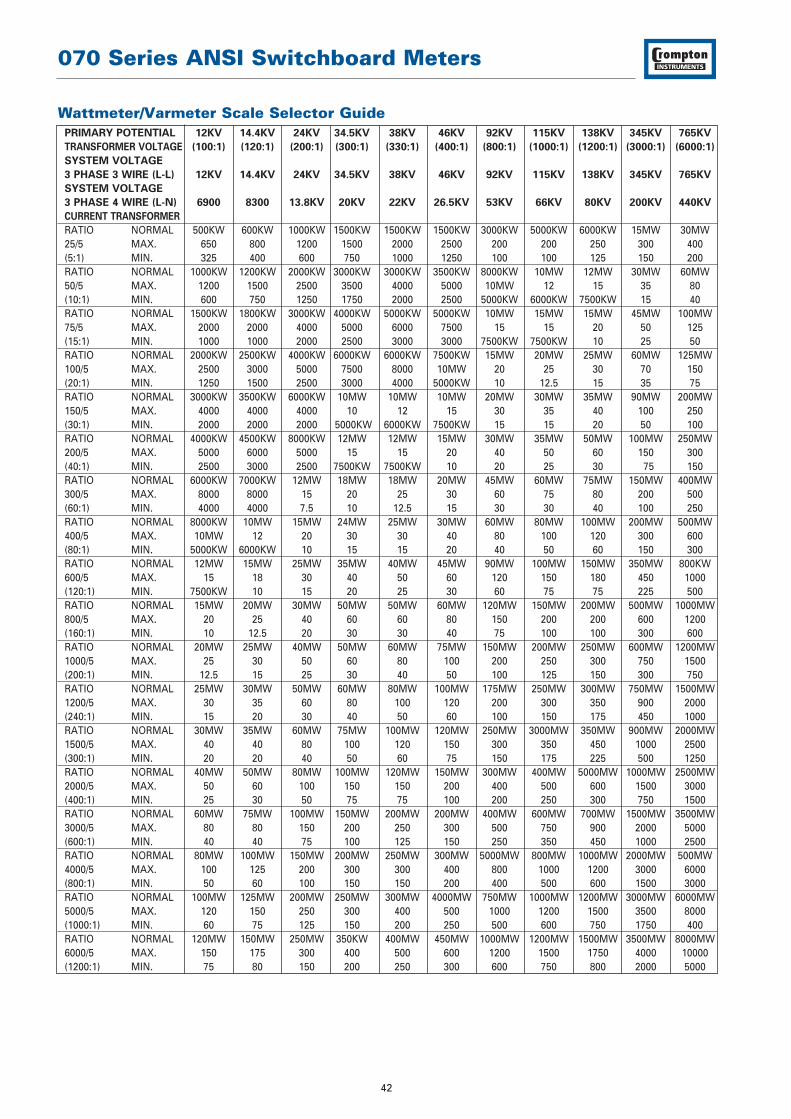
Wattmeter/Varmeter Scale Selector GuidePRIMARY POTENTIAL 120 208 240 480 600 2400 3600 4200 4800 6000 7200 8400
TRANSFORMER VOLTAGE (1:1) (1.73:1) (2:1) (4:1) (5:1) (20:1) (30:1) (35:1) (40:1) (50:1) (60:1) (70:1)
SYSTEM VOLTAGE
3 PHASE 3 WIRE (L-L) 120 208 240 480 600 2400 3600 4200 4800 6000 7200 8400
SYSTEM VOLTAGE
3 PHASE 4 WIRE (L-N) 69 120 139 277 347 1390 2100 2400 2770 3500 4160 4800
CURRENT TRANSFORMER
RATIO NORMAL 5KW 10KW 10KW 20KW 25KW 100KW 150KW 175KW 200KW 250KW 300KW 350KW25/5 MAX. 6 10 12 25 30 120 200 200 250 300 400 450(5:1) MIN. 3 5 6 12.5 15 60 100 100 125 150 200 225RATIO NORMAL 10KW 20KW 20KW 40KW 50KW 200KW 300KW 350KW 400KW 500KW 600KW 700KW50/5 MAX. 12 20 25 50 60 250 400 450 500 600 800 900(10:1) MIN. 6 10 12.5 25 30 125 200 250 250 300 400 450RATIO NORMAL 15KW 25KW 30KW 60KW 75KW 300KW 500KW 500KW 600KW 750KW 900KW 1000KW75/5 MAX. 20 30 40 80 100 400 600 700 800 1000 1200 1200(15:1) MIN. 10 15 20 40 50 200 300 350 400 500 600 600RATIO NORMAL 20KW 30KW 40KW 75KW 100KW 400KW 600KW 700KW 800KW 1000KW 1200KW 1200KW100/5 MAX. 25 40 50 100 120 500 800 900 1000 1200 1500 1500(20:1) MIN. 12.5 20 25 50 60 250 400 450 500 600 750 750RATIO NORMAL 30KW 50KW 50KW 100KW 150KW 600KW 800KW 1000KW 1200KW 1500KW 1800KW 2000KW150/5 MAX. 40 70 75 150 200 800 1200 1200 1500 2000 2400 2500(30:1) MIN. 20 35 35 75 100 400 600 600 750 1000 1000 1250RATIO NORMAL 40KW 75KW 75KW 150KW 200KW 800KW 1200KW 1200KW 1500KW 2000KW 2500KW 3000KW200/5 MAX. 50 80 100 200 250 1000 1500 1500 2000 2500 3000 3500(40:1) MIN. 25 40 50 100 125 500 750 750 1000 1250 1500 1500RATIO NORMAL 70KW 100KW 100KW 200KW 300KW 1200KW 1500KW 2000KW 2500KW 3000KW 3500KW 4500KW300/5 MAX. 75 120 150 300 400 1500 2000 2500 3000 4000 4000 5000(60:1) MIN. 35 60 75 150 200 750 1000 1250 1500 2000 2000 2500RATIO NORMAL 75KW 125KW 150KW 300KW 400KW 1500KW 2500KW 3000KW 3000KW 4000KW 5000KW 6000KW400/5 MAX. 100 150 200 400 500 2000 3000 3600 4000 5000 6000 7000(80:1) MIN. 50 75 100 200 250 1000 1500 1500 2000 2500 3000 3500RATIO NORMAL 125KW 200KW 200KW 450KW 600KW 2000KW 3000KW 4000KW 5000KW 6000KW 7500KW 8000KW600/5 MAX. 150 250 300 600 800 3000 4000 5000 6000 8000 8000 10MW(120:1) MIN. 75 125 150 300 400 1500 2000 2500 3000 4000 4000 5000KWRATIO NORMAL 150KW 250KW 300KW 600KW 800KW 3000KW 5000KW 6000KW 6000KW 8000KW 10MW 12MW800/5 MAX. 200 350 400 800 1000 4000 6000 7500 8000 10MW 12 15(160:1) MIN. 100 175 200 400 500 2000 3000 3000 40000 5000KW 6000KW 7500KWRATIO NORMAL 200KW 350KW 400KW 800KW 1000KW 4000KW 6000KW 6000KW 8000KW 10MW 12MW 15MW1000/5 MAX. 250 450 500 1000 1200 5000 8000 8000 10MW 12 15 18(200:1) MIN. 125 225 250 500 600 2500 4000 4000 5000KW 6000KW 7500KW 10RATIO NORMAL 250KW 400KW 500KW 1000KW 1200KW 5000KW 7000KW 8000KW 10MW 12MW 15MW 10MW1200/5 MAX. 300 500 600 1200 1500 6000 8000 10MW 12 15 18 20(240:1) MIN. 150 250 300 600 750 3000 4000 5000KW 6000KW 7500KW 10 10RATIO NORMAL 300KW 500KW 600KW 1200KW 1500KW 6000KW 10MW 10MW 12MW 15MW 20MW 20MW1500/5 MAX. 400 700 750 1500 2000 8000 12 12 15 20 20 25(300:1) MIN. 200 350 375 1000 1000 4000 6000KW 6000KW 7500KW 10 10 12.5RATIO NORMAL 400KW 750KW 800KW 1600KW 2000KW 8000KW 12MW 12MW 15MW 20MW 25MW 30MW2000/5 MAX. 500 800 1000 2000 2500 10MW 15 15 20 25 30 35(400:1) MIN. 250 400 500 750 1250 5000 7500KW 7500KW 10 12.5 15 20RATIO NORMAL 750KW 1000KW 1200KW 2000KW 3000KW 12MW 18MW 20MW 25MW 30MW 35MW 40MW3000/5 MAX. 800 1200 1500 3000 4000 15 20 25 30 40 40 50(600:1) MIN. 400 600 750 1500 2000 7500KW 10 12.5 15 20 20 25RATIO NORMAL 800KW 1200KW 1500KW 3000KW 4000KW 15MW 20MW 25MW 30MW 40MW 50MW 50MW4000/5 MAX. 1000 1500 2000 4000 5000 20 30 30 40 50 60 75(800:1) MIN. 500 750 1000 2000 2500 10 15 15 20 25 30 40RATIO NORMAL 1000KW 1500KW 2000KW 4000KW 5000KW 20MW 30MW 20MW 40MW 50MW 60MW 75MW5000/5 MAX. 1250 2000 2500 5000 6000 25 40 25 50 60 80 80(1000:1) MIN. 500 1000 1250 2500 3000 12.5 20 12.5 25 30 40 40RATIO NORMAL 1200KW 2000KW 2500KW 5000KW 6000KW 25MW 35MW 40MW 50MW 60MW 60MW 80MW6000/5 MAX. 1500 2500 3000 3000 8000 30 40 50 60 80 80 100(1200:1) MIN. 750 1250 1500 1500 4000 15 20 25 30 40 40 50
070 Series ANSI Switchboard Meters
42
Wattmeter/Varmeter Scale Selector GuidePRIMARY POTENTIAL 12KV 14.4KV 24KV 34.5KV 38KV 46KV 92KV 115KV 138KV 345KV 765KV
TRANSFORMER VOLTAGE (100:1) (120:1) (200:1) (300:1) (330:1) (400:1) (800:1) (1000:1) (1200:1) (3000:1) (6000:1)
SYSTEM VOLTAGE
3 PHASE 3 WIRE (L-L) 12KV 14.4KV 24KV 34.5KV 38KV 46KV 92KV 115KV 138KV 345KV 765KV
SYSTEM VOLTAGE
3 PHASE 4 WIRE (L-N) 6900 8300 13.8KV 20KV 22KV 26.5KV 53KV 66KV 80KV 200KV 440KV
CURRENT TRANSFORMER
RATIO NORMAL 500KW 600KW 1000KW 1500KW 1500KW 1500KW 3000KW 5000KW 6000KW 15MW 30MW25/5 MAX. 650 800 1200 1500 2000 2500 200 200 250 300 400(5:1) MIN. 325 400 600 750 1000 1250 100 100 125 150 200RATIO NORMAL 1000KW 1200KW 2000KW 3000KW 3000KW 3500KW 8000KW 10MW 12MW 30MW 60MW50/5 MAX. 1200 1500 2500 3500 4000 5000 10MW 12 15 35 80(10:1) MIN. 600 750 1250 1750 2000 2500 5000KW 6000KW 7500KW 15 40RATIO NORMAL 1500KW 1800KW 3000KW 4000KW 5000KW 5000KW 10MW 15MW 15MW 45MW 100MW75/5 MAX. 2000 2000 4000 5000 6000 7500 15 15 20 50 125(15:1) MIN. 1000 1000 2000 2500 3000 3000 7500KW 7500KW 10 25 50RATIO NORMAL 2000KW 2500KW 4000KW 6000KW 6000KW 7500KW 15MW 20MW 25MW 60MW 125MW100/5 MAX. 2500 3000 5000 7500 8000 10MW 20 25 30 70 150(20:1) MIN. 1250 1500 2500 3000 4000 5000KW 10 12.5 15 35 75RATIO NORMAL 3000KW 3500KW 6000KW 10MW 10MW 10MW 20MW 30MW 35MW 90MW 200MW150/5 MAX. 4000 4000 4000 10 12 15 30 35 40 100 250(30:1) MIN. 2000 2000 2000 5000KW 6000KW 7500KW 15 15 20 50 100RATIO NORMAL 4000KW 4500KW 8000KW 12MW 12MW 15MW 30MW 35MW 50MW 100MW 250MW200/5 MAX. 5000 6000 5000 15 15 20 40 50 60 150 300(40:1) MIN. 2500 3000 2500 7500KW 7500KW 10 20 25 30 75 150RATIO NORMAL 6000KW 7000KW 12MW 18MW 18MW 20MW 45MW 60MW 75MW 150MW 400MW300/5 MAX. 8000 8000 15 20 25 30 60 75 80 200 500(60:1) MIN. 4000 4000 7.5 10 12.5 15 30 30 40 100 250RATIO NORMAL 8000KW 10MW 15MW 24MW 25MW 30MW 60MW 80MW 100MW 200MW 500MW400/5 MAX. 10MW 12 20 30 30 40 80 100 120 300 600(80:1) MIN. 5000KW 6000KW 10 15 15 20 40 50 60 150 300RATIO NORMAL 12MW 15MW 25MW 35MW 40MW 45MW 90MW 100MW 150MW 350MW 800KW600/5 MAX. 15 18 30 40 50 60 120 150 180 450 1000(120:1) MIN. 7500KW 10 15 20 25 30 60 75 75 225 500RATIO NORMAL 15MW 20MW 30MW 50MW 50MW 60MW 120MW 150MW 200MW 500MW 1000MW800/5 MAX. 20 25 40 60 60 80 150 200 200 600 1200(160:1) MIN. 10 12.5 20 30 30 40 75 100 100 300 600RATIO NORMAL 20MW 25MW 40MW 50MW 60MW 75MW 150MW 200MW 250MW 600MW 1200MW1000/5 MAX. 25 30 50 60 80 100 200 250 300 750 1500(200:1) MIN. 12.5 15 25 30 40 50 100 125 150 300 750RATIO NORMAL 25MW 30MW 50MW 60MW 80MW 100MW 175MW 250MW 300MW 750MW 1500MW1200/5 MAX. 30 35 60 80 100 120 200 300 350 900 2000(240:1) MIN. 15 20 30 40 50 60 100 150 175 450 1000RATIO NORMAL 30MW 35MW 60MW 75MW 100MW 120MW 250MW 3000MW 350MW 900MW 2000MW1500/5 MAX. 40 40 80 100 120 150 300 350 450 1000 2500(300:1) MIN. 20 20 40 50 60 75 150 175 225 500 1250RATIO NORMAL 40MW 50MW 80MW 100MW 120MW 150MW 300MW 400MW 5000MW 1000MW 2500MW2000/5 MAX. 50 60 100 150 150 200 400 500 600 1500 3000(400:1) MIN. 25 30 50 75 75 100 200 250 300 750 1500RATIO NORMAL 60MW 75MW 100MW 150MW 200MW 200MW 400MW 600MW 700MW 1500MW 3500MW3000/5 MAX. 80 80 150 200 250 300 500 750 900 2000 5000(600:1) MIN. 40 40 75 100 125 150 250 350 450 1000 2500RATIO NORMAL 80MW 100MW 150MW 200MW 250MW 300MW 5000MW 800MW 1000MW 2000MW 500MW4000/5 MAX. 100 125 200 300 300 400 800 1000 1200 3000 6000(800:1) MIN. 50 60 100 150 150 200 400 500 600 1500 3000RATIO NORMAL 100MW 125MW 200MW 250MW 300MW 4000MW 750MW 1000MW 1200MW 3000MW 6000MW5000/5 MAX. 120 150 250 300 400 500 1000 1200 1500 3500 8000(1000:1) MIN. 60 75 125 150 200 250 500 600 750 1750 400RATIO NORMAL 120MW 150MW 250MW 350KW 400MW 450MW 1000MW 1200MW 1500MW 3500MW 8000MW6000/5 MAX. 150 175 300 400 500 600 1200 1500 1750 4000 10000(1200:1) MIN. 75 80 150 200 250 300 600 750 800 2000 5000

070 Series ANSI Switchboard Meters
43
A.C. Wattmeter
A.C. Varmeter
A.C. Wattmeters
Product Codes – 1 element, transformer rated. 50/60Hz.Taut Band. Integral transducer. Accuracy 1.0%. 50/60Hz
Measured 41⁄2" Square Flange 83⁄4" Square Flange
System Scales Standard Case Sealed Case Standard Case
Catalogue No. Hi-Shock Catalogue No.
Catalogue No.
1 2 5 120V TO SUIT •/+077-215A-QQ** 078-215J-QQ** •079-215A-QQ**1 2 5 240V TO SUIT 077-215A-QS** 078-215J-QS** 079-215A-QS**
For connection diagram please see Fig. 21 page 60.
Product Codes – 2 element, transformer rated. 50/60Hz.Taut Band. Integral transducer. Accuracy 1.0%. 50/60Hz3 3 5 120V TO SUIT •/+077-218A-QQ** 078-218J-QQ** •079-218A-QQ**3 3 5 208V TO SUIT •/+077-218A-QR** 078-218J-QR** •079-218A-QR**3 3 5 240V TO SUIT •/+077-218A-QS** 078-218J-QS** 079-218A-QS**3 3 5 380V TO SUIT •/+077-218A-QX** 078-218J-QX** 079-218A-QX**3 3 5 480V TO SUIT •/+077-218A-QT** 078-218J-QT** 079-218A-QT**
For connection diagram please see Fig. 25 page 60.
Product Codes – 21⁄2 element, transformer rated. 50/60Hz.Taut Band. Integral transducer. Accuracy 1.0%. 50/60Hz3 4 5 69V TO SUIT •/+077-219A-QL** 078-219J-QL** •079-219A-QL**3 4 5 120V TO SUIT •/+077-219A-QQ** 078-219J-QQ** •079-219A-QQ**3 4 5 277V TO SUIT 077-219A-QY** 078-219J-QY** 079-219A-QY**3 4 5 346V TO SUIT 077-219A-QZ** 078-219J-QZ** 079-219A-QZ**
For connection diagram please see Fig. 28 page 60.
Product Codes – Phase Shifting TransformersFor use with above Wattmeters, when VAr measurement with external phase shifter is required.
3 3 120V 855-956A-PR 855-956J-PR 855-956A-PR3 4 120V 855-957A-PR 855-957J-PR 855-957A-PR3 4 69V 855-957A-NZ 855-957J-NZ 855-957A-NZ
A.C. Varmeters
Product Codes – 2 element, transformer rated. 50/60Hz.Taut Band. Integral transducer. Accuracy 1.0%. 50/60Hz3 3 5 120V TO SUIT •/+077-31LA-QQ** 078-31LJ-QQ**3 3 5 208V TO SUIT •/+077-31LA-QR**-C6 078-31LJ-QR** 3 3 5 240V TO SUIT 077-31LA-QS** 078-31LJ-QS** 3 3 5 380V TO SUIT 077-31LA-QX** 078-31LJ-QX** 3 3 5 480V TO SUIT 077-31LA-QT** 078-31LJ-QT**
For connection diagram please see Fig. 32 page 61.
Product Codes – 21⁄2 element, transformer rated. 50/60Hz.Taut Band. Integral transducer. Accuracy 1.0%.50/60Hz3 4 5 120V TO SUIT •/+077-31UA-QQ** 078-31UJ-QQ** •079-31UA-QQ**3 4 5 208V TO SUIT 077-31UA-QR** 078-31UJ-QR** •079-31UA-QR**3 4 5 480V TO SUIT 077-31UA-QT** 078-31UJ-QT** 079-31UA-QT**
For connection diagram please see Fig. 32 page 61.
• UL recognised File # E87815 + CSA Approved File # LR52592** Specify C.T. (Current Transformer) and V.T. (Voltage Transformer) ratios if used, and
preferred scale at time of ordering.
Phas
es
Wire
s
Ampe
res
1 VA
max
. Bur
den
Volts
1 VA
max
. Bur
den

070 Series ANSI Switchboard Meters
44
RTD Temperature Meter
RTD Temperature Meters*
Product Codes – Accuracy 1.0% of span.Self-contained for 10 Ohm copper or 100 Ohm platinum RTD. (ResistanceTemperature Detector) - Specify copper or platinum at time of ordering.
41⁄2" Square Flange
Rating Scaling* Standard Case Sealed Case Hi-Shock
Catalogue No. Catalogue No.
110/130V 20-140°C 077-45RA-**QF-PQ 078-45RJ-**QF-PQ50/60Hz
110/130V 0-150°C 077-45RA-**QE-PQ 078-45RJ-**QE-PQ50/60Hz
110/130V 0-200°C 077-45RA-**QG-PQ 078-45RJ-**QG-PQ50/60Hz
For connection diagrams please see Fig. 17 page 59.
Thermocouple Temperature Meters
Product Code – Accuracy 1% of span.Suitable for type J and K. Cold junction compensation and thermocouple break indication isprovided. Specifiy type J or K and temperature at time of ordering.
41⁄2" Square Flange
Rating Standard Case Catalogue No.
110/130V 077-45TA-••PM50/60Hz
For connection diagrams please see Fig. 18 page 59.
Tap Position Indicator
Product CodeTo show transformer tap, hoist or valve position using 3 wire system for 1-18 tap positionsusing 400 Ohm steps.
41⁄2" Square Flange 83⁄4" Square Flange
Rating Scaling* Standard Case Sealed Case Hi-Shock Standard Case
Catalogue No. Catalogue No. Catalogue No.
110/220/240V 1-18 taps 077-45P- Not available Not available50/60Hz
For connection diagrams please see Fig. 20 page60.
Select nearest higher rated voltmeter and specify requirement• UL recognised File # E87815 * Other ranges available upon •• JT for type J, KT for type K thermocouple request - Consult Factory.
** RI for 10 ohm Copper or R2 for 100ohm platinum.
*** Specify input and scale

070 Series ANSI Switchboard Meters
45
Elapsed Time Meters
Product Codes – 99,999.99 hours, non reset. Burden 2.5VA. 50 or 60HzSynchronous motor running time meter with a running indicator.
41⁄2" Square Flange 83⁄4" Square Flange
Rating Standard Case Sealed Case Hi-Shock Standard Case
Catalogue No. Catalogue No. Catalogue No.
110/130V 50Hz •077-155A-PNZH-C5 078-155J-PNZH-C5 Not available200/250V 50Hz •077-155A-RNZH-C5 078-155J-RNZH-C5 Not available
480V 50Hz •077-155A-SEZH-C5 078-155J-SEZH-C5 Not available110/130V 60Hz •077-156A-PNZH-C6 078-156J-PNZH-C6 Not available200/250V 60Hz •077-156A-RNZH-C6 078-156J-RNZH-C6 Not available
480V 60Hz •077-156A-SEZH-C6 078-156J-SEZH-C6 Not available12/24/40/110V D.C. 077-151A-
A.C. Phase Sequence, Phase Failure Indicators
Product Codes – Neon Bulb Type. Burden 2.5VA2 neon bulbs for phase sequence indication - first marked correct 1-2-3, secondmarked incorrect 3-2-1. 3 neon bulbs for phase failure indication - first marked 1,second marked 2, third marked 3.
41⁄2" Square Flange 83⁄4" Square Flange
Rating Standard Case Sealed Case Hi-Shock Standard Case
Catalogue No. Catalogue No. Catalogue No.
100/150V 50/60Hz 077-12PA-P2C6 Not available Not available151/300V 50/60Hz 077-12PA-P3C6 Not available Not available301/500V 50/60Hz 077-12PA-P4C6 Not available Not available
For connection diagrams please see Fig. 1 page 58.
D.C. Indicators for Tachometer Generators
Product Code41⁄2" Square Flange 83⁄4" Square Flange
Rating Standard Case Sealed Case Hi-Shock Standard Case
Catalogue No. Catalogue No. Catalogue No.
D.C. Volts 077-052A-*** 078-052J-*** 079-052A-***
Select nearest higher rated voltmeter and specify requirement• UL recognised File # E87815 * Other ranges available upon •• JT for type J, KT for type K thermocouple request - Consult Factory.
** RI for 10 ohm or R2 to 100ohm platinum.
*** Specify input and scale
Elapsed Time Meter
A.C. Phase Sequence and Phase Failure
Indicator

070 Series ANSI Switchboard Meters
46
A.C. Power Factor Meter
SpecificationRatings, self-contained: Current windings 5 amperes.
Voltage windings minimum 50 volts, maximum 600 voltsAccuracy Class: 1.0Overshoot: 33%External Temperature 0.5% fid max.Influence: External Field Influence: 3% fid max.Frequency Range: 50Hz or 60Hz standard, 25-3000Hz optional (Specify)Frequency Influence: Single phase instruments, 59 to 61Hz 1.0% fid max.
Polyphase instruments ±10% deviation from 69Hz: 1.0%Overload capacity: Current coils 1000% momentarily, 100% for 15 minutes
and 25% indefinitely.Voltage circuits 25% indefinitely.
Burdens: Each current circuit, 1.5VA approxEach voltage circuit 1VA approxMeasuring systems 077-427 - 3 or 4 wire
Ranges available: Lag 0.5-1 - 0.5 lead power factorLag 0.2-1 - 0.8 lead power factor
JIS dimension product available on request. Instruments may be used on loadsdown to 20% of current rating and between 90% and 110% of voltage rating.
Product Codes – Balanced Load Accuracy ±1%Measured 41⁄2" Square Flange 83⁄4" Square Flange
System Scales Standard Case Sealed Case Standard Case
Catalogue No. Hi-Shock Catalogue No.
Catalogue No.
1 2 5 120V 0.5-1-0.5 •/+077-425A-QQAD 078-425J-QQAD •079-425A-QQAD1 2 5 240V 0.5-1-0.5 •/+077-425A-QSAD 078-427J-QSAD •079-427A-QSAD3 3⁄4 5 120V 0.5-1-0.5 •/+077-427A-QQAD 078-427J-QQAD •079-427A-QAAD3 3⁄4 5 208V 0.5-1-0.5 •/+077-427A-QRAD 078-427J-QRAD •079-427A-QRAD3 3⁄4 5 240V 0.5-1-0.5 •/+077-427A-QSAD 078-427J-QSAD •079-427A-QSAD3 3⁄4 5 480V 0.5-1-0.5 077-427A-QTAD 078-427J-QTAD 079-427A-QTAD
For connection diagrams please see Fig. 13 & 15 page 59.
Product Codes – Unbalanced Load Accuracy ±1%Measured 41⁄2" Square Flange 83⁄4" Square Flange
System Scales Standard Case Sealed Case Standard Case
Catalogue No. Hi-Shock Catalogue No.
Catalogue No.
3 3 5 120V 0.5-1-0.5 077-TFUA-QQAD – –3 3 5 240V 0.5-1-0.5 077-TFUA-QSAD – –
For connection diagrams please see Fig. 12 page 59.
• UL Recognised File # E87815 + CSA Approved File # LR52592
A.C. Power Factor Meter
Phas
es
Wire
s
Ampe
res
2 VA
max
. Bur
den
Volts
1 VA
max
. Bur
den
Phas
es
Wire
s
Ampe
res
2 VA
max
. Bur
den
Volts
1 VA
max
. Bur
den
070 Series ANSI Switchboard Meters
47
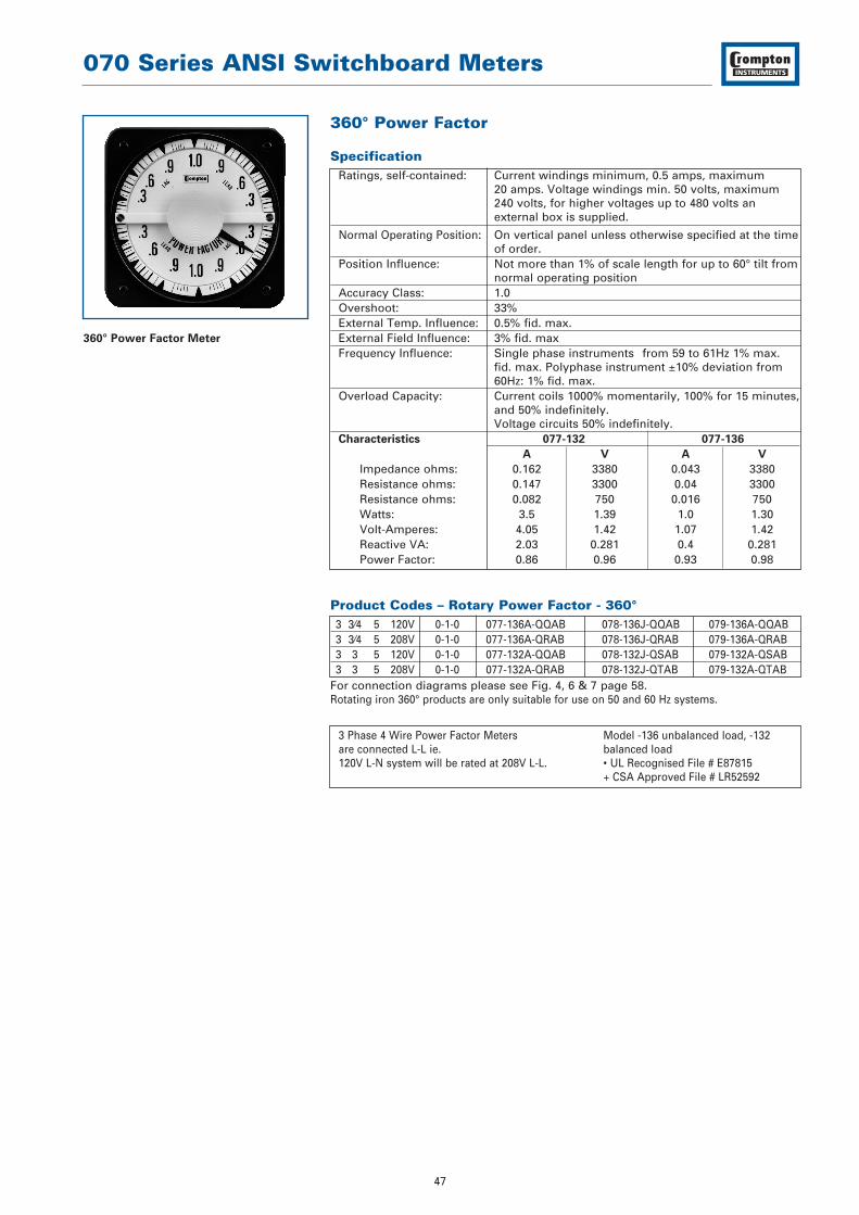
360° Power Factor
SpecificationRatings, self-contained: Current windings minimum, 0.5 amps, maximum
20 amps. Voltage windings min. 50 volts, maximum 240 volts, for higher voltages up to 480 volts an external box is supplied.
Normal Operating Position: On vertical panel unless otherwise specified at the timeof order.
Position Influence: Not more than 1% of scale length for up to 60° tilt fromnormal operating position
Accuracy Class: 1.0Overshoot: 33%External Temp. Influence: 0.5% fid. max.External Field Influence: 3% fid. maxFrequency Influence: Single phase instruments from 59 to 61Hz 1% max.
fid. max. Polyphase instrument ±10% deviation from 60Hz: 1% fid. max.
Overload Capacity: Current coils 1000% momentarily, 100% for 15 minutes,and 50% indefinitely. Voltage circuits 50% indefinitely.
Characteristics 077-132 077-136
A V A V
Impedance ohms: 0.162 3380 0.043 3380Resistance ohms: 0.147 3300 0.04 3300Resistance ohms: 0.082 750 0.016 750Watts: 3.5 1.39 1.0 1.30Volt-Amperes: 4.05 1.42 1.07 1.42Reactive VA: 2.03 0.281 0.4 0.281Power Factor: 0.86 0.96 0.93 0.98
Product Codes – Rotary Power Factor - 360°3 3⁄4 5 120V 0-1-0 077-136A-QQAB 078-136J-QQAB 079-136A-QQAB3 3⁄4 5 208V 0-1-0 077-136A-QRAB 078-136J-QRAB 079-136A-QRAB3 3 5 120V 0-1-0 077-132A-QQAB 078-132J-QSAB 079-132A-QSAB3 3 5 208V 0-1-0 077-132A-QRAB 078-132J-QTAB 079-132A-QTAB
For connection diagrams please see Fig. 4, 6 & 7 page 58.Rotating iron 360° products are only suitable for use on 50 and 60 Hz systems.
3 Phase 4 Wire Power Factor Meters Model -136 unbalanced load, -132 are connected L-L ie. balanced load120V L-N system will be rated at 208V L-L. • UL Recognised File # E87815
+ CSA Approved File # LR52592
360° Power Factor Meter

070 Series ANSI Switchboard Meters
48
360° Rotary Synchroscope
SpecificationRating, self-contained: 120V A.C.Frequency rating: 50 or 60Hz (specify), 400Hz optionalNormal Operating Position: On vertical panel unless otherwise specified at time
of orderPosition Influence: Not more than 3.6 mechanical degrees deviation for up
to 60° tilt from normal operating position.Accuracy: 2 degreesOvershoot: 33% maximumResponse time: 3 seconds maximum for 180° deflectionSensitivity at synchronism: 3 electrical degrees maximumExternal field influence: 3% maximum in 5 oersted fieldPull in frequency: 58HzDrop-out frequency: 57HzDielectric test: Live parts to case, including panel: 2600V RMS
for 1 minute.Between running and 1500V RMS for 1 minuteincoming circuits:Overload capacity: 50% indefinitelyCharacteristics Incoming circuit Running circuit
Impedance ohms: 4670 5335Resistance ohms: 4020 5240Resistance ohms: 2380 1058Reactive Volt amps: 1.57 0.535Volt-amps: 3.08 2.7Power factor: 0.86 0.98Watts: 2.66 2.65
Product Codes – Pivot and Jewel41⁄2" Square Flange 83⁄4" Square Flange
Rating Scaling* Standard Case Sealed Case Hi-Shock Standard Case
Catalogue No. Catalogue No. Catalogue No.
120V 50Hz SLOW FAST •/+077-145A-PRAE-C5 078-145J-PRAE-C5 •079-145A-PRAE-C5120V 60Hz SLOW FAST •/+077-146A-PRAE-C6 078-146J-PRAE-C6 •079-146A-PRAE-C6120V 400Hz SLOW FAST 077-144A-PRAE-C4 078-144J-PRAE-C4 079-144A-PRAE-C4For connection diagrams please see Fig. 10 page 59.
Alternate voltage of 240V, use code RR • UL Recognised File # E87815 instead of PR. + CSA Approved File # LR52592
360° Rotary Synchroscope

070 Series ANSI Switchboard Meters
49
360° A.C. LED Synchroscope
SpecificationVoltage: 120, 240, 480 Volts A.C. or via P.T.Frequency: 40/65HzBurden @ 60Hz: 4VA maximum
Suitable for single or three phase systems Safety: IEC1010-1(300V A.C. rms installation degree 2)Dielectric: 4kV rms for 1 minuteIsolation: BUS/GEN/RELAYVibration: To Lloyds shipping specification
Product Codes41⁄2" Square Flange
Rating Scaling Standard Case
Catalogue No.
120V 40/65Hz SLOW FAST 077-14AU-PQYY-FQ240V 40/65Hz SLOW FAST 077-14AU-RRYY-FQ480V 40/65Hz SLOW FAST 077-14AU-SEYY-FQ
For connection diagrams please see Fig. 8 page 58.
A.C. Synchrocheck Relay and LED 360° Synchroscope
SpecificationVoltage: 110/120V (115V nominal)
220/240V (230V nominal)380/480V (430V nominal)
Phase Difference: +0 to 20° ±1°Voltage Difference: +0 to 20% ±2%Time Delay: 0 to 2.5 seconds +10%
Product Codes41⁄2" Square Flange
Rating Scaling Standard Case
Catalogue No.
Live Bus110/120V 40/65Hz SLOW FAST 077-14GU-POYY-FQ220/240V 40/65Hz SLOW FAST 077-14GU-RSYY-FQ380/480V 40/65Hz SLOW FAST 077-14GU-SZYY-FQ
Dead Bus110/120V 40/65Hz SLOW FAST 077-14HU-POYY-FQ220/240V 40/65Hz SLOW FAST 077-14HU-RSYY-FQ380/480V 40/65Hz SLOW FAST 077-14HU-SZYY-FQ
Live Bus120V 40/65Hz SLOW FAST 077-14LU-PQYY-FQ240V 40/65Hz SLOW FAST 077-14LU-RRYY-FQ480V 40/65Hz SLOW FAST 077-14LU-SEYY-FQ
Dead Bus120V 40/65Hz SLOW FAST 077-14DU-PQYY-FQ240V 40/65Hz SLOW FAST 077-14DU-RRYY-FQ480V 40/65Hz SLOW FAST 077-14DU-SEYY-FQ
For connection diagrams please see Fig. 9 page 58.
In the 0.77-14G and 0.77-14H models, the generator voltage is free to track the bus voltage (+ the voltage difference preset) over the input voltage range. In the 077-14L and 077-14D models, the generator voltage is to match the nominal input (bus) voltage specified (within the voltage difference preset).
360° A.C. LED Synchroscope
A.C. Synchrocheck Relay
& LED 360° Synchroscope
070 Series ANSI Switchboard Meters
50
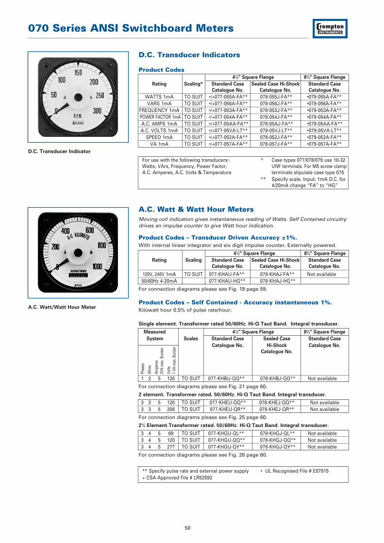
D.C. Transducer Indicators
Product Codes41⁄2" Square Flange 83⁄4" Square Flange
Rating Scaling* Standard Case Sealed Case Hi-Shock Standard Case
Catalogue No. Catalogue No. Catalogue No.
WATTS 1mA TO SUIT •/+077-055A-FA** 078-055J-FA** •079-055A-FA**VARS 1mA TO SUIT •/+077-056A-FA** 078-056J-FA** •079-056A-FA**
FREQUENCY 1mA TO SUIT •/+077-053A-FA** 078-053J-FA** •079-053A-FA**POWER FACTOR 1mA TO SUIT •/+077-054A-FA** 078-054J-FA** •079-054A-FA** A.C. AMPS 1mA TO SUIT •/+077-05AA-FA** 078-05AJ-FA** •079-05AA-FA** A.C. VOLTS 1mA TO SUIT •/+077-05VA-LT** 078-05VJ-LT** •079-05VA-LT**
SPEED 1mA TO SUIT •/+077-052A-FA** 078-052J-FA** •079-052A-FA**VA 1mA TO SUIT •/+077-057A-FA** 078-057J-FA** •079-057A-FA**
For use with the following transducers:- * Case types 077/078/079 use 10-32 Watts, VArs, Frequency, Power Factor, UNF terminals. For M5 screw clampA.C. Amperes, A.C. Volts & Temperature terminals stipulate case type 075
** Specify scale. Input: 1mA D.C. for 4/20mA change “FA” to “HG”
A.C. Watt & Watt Hour MetersMoving coil indication gives instantaneous reading of Watts. Self Contained circuitrydrives an impulse counter to give Watt hour indication.
Product Codes – Transducer Driven Accuracy ±1%.With internal linear integrator and six digit impulse counter. Externally powered.
41⁄2" Square Flange 83⁄4" Square Flange
Rating Scaling Standard Case Sealed Case Hi-Shock Standard Case
Catalogue No. Catalogue No. Catalogue No.
120V, 240V 1mA TO SUIT 077-KHAU-FA** 078-KHAJ-FA** Not available50/60Hz 4-20mA 077-KHAU-HG** 078-KHAJ-HG**
For connection diagrams please see Fig. 19 page 59.
Product Codes – Self Contained - Accuracy instantaneous 1%.Kilowatt hour 0.5% of pulse rate/hour.
Single element. Transformer rated 50/60Hz. Hi-Q Taut Band. Integral transducer.
Measured 41⁄2" Square Flange 83⁄4" Square Flange
System Scales Standard Case Sealed Case Standard Case
Catalogue No. Hi-Shock Catalogue No.
Catalogue No.
1 2 5 120 TO SUIT 077-KHBU-QQ** 078-KHBJ-QQ** Not available
For connection diagrams please see Fig. 21 page 60.
2 element. Transformer rated. 50/60Hz. Hi-Q Taut Band. Integral transducer.
3 3 5 120 TO SUIT 077-KHEU-QQ** 078-KHEJ-QQ** Not available3 3 5 208 TO SUIT 077-KHEU-QR** 078-KHEJ-QR** Not available
For connection diagrams please see Fig. 25 page 60.
21⁄2 Element.Transformer rated. 50/60Hz. Hi-Q Taut Band. Integral transducer.
3 4 5 69 TO SUIT 077-KHGU-QL** 078-KHGJ-QL** Not available3 4 5 120 TO SUIT 077-KHGU-QQ** 078-KHGJ-QQ** Not available3 4 5 277 TO SUIT 077-KHGU-QY** 078-KHGJ-QY** Not available
For connection diagrams please see Fig. 28 page 60.
** Specify pulse rate and external power supply • UL Recognised File # E87815+ CSA Approved File # LR52592
D.C. Transducer Indicator
A.C. Watt/Watt Hour Meter
Phas
es
Wire
s
Ampe
res
2VA
max
. Bur
den
Volts
1 VA
max
. Bur
den

070 Series ANSI Switchboard Meters
51
LED Digital / Analogue CombinationThe Crompton model 077-DI features a combination of the traditional 250° 41⁄2"switchboard indicator with the benefits of wide angle visibility plus trend indication.This rugged shock and vibration resistant taut band design provides precisionaccuracy and instantaneous reading via the bright in dial mounted 31⁄2 digit LED display.
DescriptionModel 077-DI digital analogue indicators are ideal for all applications where movingpointer instruments are preferable to indicate trend while simultaneously displayinga high visibility precision LED readout for increased user interface.Packaged in a weather resistant case, the 077-DI is interchangeable with otheranalogue and digital instruments designed to directly mount in to a standard ANSI-C39. 41⁄2" switchboard cut-out.Available in side, center, or off-set zero versions the 077-DI can accept A.C. Current,Voltage, Frequency, Watts, VArs and Phase Angle or D.C.Current and Voltage directinputs as well as a wide range of transducer outputs making it suitable for a varietyof other applications including low-load current, temperature, speed,watt/vars,percent and level.
SpecificationInputs: D.C. Voltage: 20mV-600V (1MΩ input impedance as standard)
D.C. Current: 1mA-1A, 4 to 20mA (Voltage drop 200mV nominal).External shunt operation (50mV and 100mV).A.C. Voltage: 200mV-600V (1 kΩ / volt)A.C. Current: 1mA-999mA (Using internal shunt, voltage drop 200mV nominal). 1A, 2A, 5A & 10A using internal current transformer.
Common mode rejection: =>80dB @ 50/60HzOverload: Voltage: x 1.2 continuous. x1.5 for 10 seconds.
Current using internal CT: x 1.2 continuous. x 10 for 10 seconds.
External Power Requirement: Standard: 120 & 240V ±15%.Optional: 480V ±15% A.C. 40 to 60Hz
Burden: 3VA @ 60HzD.C.: Standard: 12, 24, 48,110 & 125V ±15%Display Analogue: Long scale moving coil. 250° deflection. Scale
length 6.8inches. Response time less than 2.5 seconds.Display Options: Center or offset zero. Scale plate in colors other than
white. Colored lines or segments on scale. Slower response time.
Digital Display: 31⁄2 digit red LED. 7 segment (7.6mm, 0.3" high). Right hand decimal points. Polarity indication: positive / none. Negative / horizontal bar “ - ”.Update time (standard): 1 per second
Accuracy – Analogue: D.C & A.C: ±1% of FSD (calibrated at 25°C)Accuracy – Digital: DC: ±0.05% of reading ±1 count ±100ppm of
reading / °C. (Maximum).A.C. current: 0-1 Amp ±0.1% reading ±3 counts ±150ppm of reading / °C.A.C. current: 0-10 amps ±0.1% reading ±10 counts ±150ppm of reading / °C (maximum) A.C. Voltage: ±0.1% of reading ±3 counts ±150ppm of reading / °C. (maximum) Zero ±1 count ±0.2 counts/°C (maximum) D.C. offset scale only Warm up time: 1 minute
Long Term Stability: ±2 countsCalibration Check: Recommended 12 monthly intervalsEnclosure Code: IP54 (Optional IP55 using panel gasket)Operational Temperature: 0 to +60°C (32° to 140°F).Storage Temperature: -20 to +60°C (-4° to 140°F)Humidity: Up to 90% relative @ 55°C. Tests to BS2011 part 2DA.Isolation Test Voltage: 2kV RMS 60Hz for 1 minuteInterference Rejection: To IEEE STD472, ANSI C37 90A,
SEN 361503, IEC 255-4Approvals: EMC and LVD
UL recognised file E140758
Features
Rugged shock and vibration taut banddesign
High accuracy LED display
Wide selection of AC and DC inputs
Maximum trend indication visibility
Input isolation
External decimal point selection option
Interchangeable with 41⁄2" switchboardmeters
Benefits
Cost effective
Meets all the requirements of ANSI-C39.1 (1981)
IP54 (NEMA 3) protection.
Optional IP55 (NEMA 4) gasket
Bump, shock and vibration proof
Customised options and features
Applications
Switchgear
Distribution systems
Generator sets
Control panels
Energy management
Building management
Utility power monitoring
Process control
Motor control
Approvals
UL recognised File No: E140758

070 Series ANSI Switchboard Meters
52
LED Digital/Analogue Combination
Product Codes – A.C. Voltmeters - direct reading (40/2000Hz)***Digital accuracy ±0.1% ±3 counts analogue accuracy ±1%.
Rating Scaling* Catalogue No.
200mV 0-200mV 077-DIWA-KAKA-C6-**250mV 0-250mV 077-DIWA-KDKD-C6-**500mV 0-500mV 077-DIWA-KMKM-C6-**1V 0-1V 077-DIWA-LALA-C6-**5V 0-5V 077-DIWA-LSLS-C6-**10V 0-10V 077-DIWA-MTMT-C6-**15V 0-15V 077-DIWA-NDND-C6-**30V 0-30V 077-DIWA-NLNL-C6-**150V 0-150V 077-DIWA-PZPZ-C6-**250V 0-250V 077-DIWA-RSRS-C6-**300V 0-300V 077-DIWA-RXRX-C6-**500V 0-500V 077-DIWA-SFSF-C6-**600V 0-600V 077-DIWA-SJSJ-C6-**
For connection diagrams please see Fig. 45 page 62.
Product Codes – A.C. Voltmeters Transformer Rated (40/2000Hz)***Rating Scaling* Catalogue No.
150V 0-300V 077-DIWA-PZRX-C6-**150V 0-600V 077-DIWA-PZSJ-C6-**150V 0-750V 077-DIWA-PZSM-C6-**150V 0-3000V 077-DIWA-PZUA-C6-**143V 0-5000V 077-DIWA-PTUJ-C6-**150V 0-5250V 077-DIWA-PZUL-C6-**150V 0-6000V 077-DIWA-PZUP-C6-**150V 0-9000V 077-DIWA-PZUY-C6-**150V 0-15KV 077-DIWA-PZWC-C6-**150V 0-18KV 077-DIWA-PZWD-C6-**150V 0-45KV 077-DIWA-PZWJ-C6-**150V 0-60KV 077-DIWA-PZWL-C6-**
For connection diagrams please see Fig. 45 page 62.
Product Codes – A.C. Ammeters - direct reading (40/2000Hz)***Rating Scaling* Catalogue No.
1A 0-1A 077-DIBA-LALA-C6-**1.5A 0-1.5A 077-DIBA-LCLC-C6-**2A 0-2A 077-DIBA-LELE-C6-**3A 0-3A 077-DIBA-LJLJ-C6-**5A 0-5A 077-DIBA-LSLS-C6-**8A 0-8A 077-DIBA-MJMJ-C6-**10A 0-10A 077-DIBA-MTMT-C6-**
For connection diagrams please see Fig. 45 page 62.
Product Codes – Power SupplyMU - 12 Volts D.C. PQ - 120 Volts A.C.Z2 - 130 Volts D.C. PR - 120 Volts D.C.BD - 24 Volts D.C. RR - 240 Volts A.C.PO - 115 Volts A.C. PS - 125 Volts D.C.NR - 48 Volts D.C.
* Other scalings available.** Specify power supply voltage, for the code, see Power Supply Codes table. *** Case types 077/078/079 use 10-32 UNF terminals.
For M5 screw clamp terminals stipulate case type 075
A.C. Voltmeter
A.C. Ammeter

070 Series ANSI Switchboard Meters
53
LED Digital/Analogue Combination
Product Codes – A.C. Ammeters Transformer Rated (40/2000Hz)Digital accuracy ±0.1% ±1 counts analogue accuracy ±1%.
Rating Scaling* Catalogue No.
5A 0-10A 077-DIBA-LSMT-C6-**5A 0-15A 077-DIBA-LSND-C6-**5A 0-20A 077-DIBA-LSNG-C6-**5A 0-25A 077-DIBA-LSNJ-C6-**5A 0-30A 077-DIBA-LSNL-C6-**5A 0-40A 077-DIBA-LSNP-C6-**5A 0-50A 077-DIBA-LSNT-C6-**5A 0-60A 077-DIBA-LSNW-C6-**5A 0-75A 077-DIBA-LSPB-C6-**5A 0-80A 077-DIBA-LSPD-C6-**5A 0-100A 077-DIBA-LSPK-C6-**5A 0-150A 077-DIBA-LSPZ-C6-**5A 0-200A 077-DIBA-LSRL-C6-**5A 0-250A 077-DIBA-LSRS-C6-**5A 0-300A 077-DIBA-LSRX-C6-**5A 0-400A 077-DIBA-LSSC-C6-**5A 0-500A 077-DIBA-LSSF-C6-**5A 0-600A 077-DIBA-LSSJ-C6-**5A 0-750A 077-DIBA-LSSM-C6-**5A 0-800A 077-DIBA-LSSN-C6-**5A 0-1000A 077-DIBA-LSSS-C6-**5A 0-1200A 077-DIBA-LSSU-C6-**5A 0-1500A 077-DIBA-LSTC-C6-**5A 0-1600A 077-DIBA-LSTE-C6-**
For connection diagrams please see Fig. 45 page 62.
Product Codes – A.C. Frequency MetersSelf contained 110/130• Volts rating. Moving Coil Indicator Integral transducer
Centre Accuracy Scaling* Catalogue No.
Frequency
50Hz ±0.15 45-55Hz 077-DZLA-PNAG-AG50Hz ±0.15 46-54Hz 077-DZLA-PNAH-AH55Hz ±0.25 45-65Hz 077-DZLA-PNAJ-AJ60Hz ±0.25 50-70Hz 077-DZLA-PNAL-AL60Hz ±0.15 55-65Hz 077-DZLA-PNAN-AN60Hz ±0.15 56-64Hz 077-DZLA-PNAO-AO60Hz ±0.08 58-62Hz 077-DZLA-PNAT-AT400Hz ±1.3 350-450Hz 077-DZLA-PNBH-BH400Hz ±1.25 360-440Hz 077-DZLA-PNBI-BI400Hz ±0.08 380-420Hz 077-DZLA-PNBK-BK
For connection diagrams please see Fig. 44 page 62.
Product Codes – Power SupplyMU - 12 Volts D.C. PQ - 120 Volts A.C.Z2 - 130 Volts D.C. PR - 120 Volts D.C.BD - 24 Volts D.C. RR - 240 Volts A.C.PO - 115 Volts A.C. PS - 125 Volts D.C.NR - 48 Volts D.C.
• Alternative voltage rating 200/250V specify RN instead of PN• Alternative voltage rating 380/480V specify SE instead of PN* Other scales are available.** Specify power supply voltage, for the code, see Power Supply Codes table.
A.C. Ammeter
A.C. Frequency Meter

070 Series ANSI Switchboard Meters
54
LED Digital/Analogue Combination
Product Codes – D.C. Voltmeters - Direct ReadingDigital accuracy ±0.5% ±1 counts analogue accuracy ±1%.
Rating Scaling* Catalogue No.
200mV 0-200mV 077-DIVA-KAKA-**250mV 0-250mV 077-DIVA-KDKD-**500mV 0-500mV 077-DIVA-KMKM-**1V 0-1V 077-DIVA-LALA-**5V 0-5V 077-DIVA-LSLS-**10V 0-10V 077-DIVA-MTMT-**15V 0-15V 077-DIVA-NDND-**30V 0-30V 077-DIVA-NLNL-**50V 0-50V 077-DIVA-NTNT-**75V 0-75V 077-DIVA-PBPB-**80V 0-80V 077-DIVA-PDPD-**150V 0-150V 077-DIVA-PZPZ-**300V 0-300V 077-DIVA-RXRX-**400V 0-400V 077-DIVA-SCSC-**500V 0-500V 077-DIVA-SFSF-**600V 0-600V 077-DIVA-SJSJ-**150-0-150V 150-0-150V 077-DINA-RXRX-**300-0-300V 300-0-300V 077-DINA-SJSJ-**600-0-600V 600-0-600V 077-DINA-SUSU-**
For connection diagrams please see Fig. 45 page 62.
Product Codes – Transducer Indicators***For use with the following transducers: Catalogue No.
Watts, VArs, Frequency, Power Factor, A.C. Amperes 077-DITA-****-**A.C. Volts, Temperature
For connection diagrams please see Fig. 45 page 62.
Product Codes – Indicators for Tachometer GeneratorsRating Scaling* Catalogue No.
A.C. or D.C. FPM or RPM 077-DI2A-****-**
For connection diagrams please see Fig. 45 page 62.
Product Codes – Power SupplyMU - 12 Volts D.C. PQ - 120 Volts A.C.Z2 - 130 Volts D.C. PR - 120 Volts D.C.BD - 24 Volts D.C. RR - 240 Volts A.C.PO - 115 Volts A.C. PS - 125 Volts D.C.NR - 48 Volts D.C.
* Other scales are available.** Specify power supply voltage, for the code, see Power Supply Codes table. *** Case types 077/078/079 use 10-32 UNF terminals.
For M5 screw clamp terminals stipulate case type 075**** Specify input and scaling
D.C. Voltmeter
Transducer Indicator

070 Series ANSI Switchboard Meters
55
LED Digital/Analogue Combination
Product Codes – D.C. Ammeters - Shunt RatedDigital accuracy ±0.5% ±1 counts analogue accuracy ±1%.
Rating Scaling* Catalogue No.
50mV-4mA Scaled to 077-DIAA-EY50-0-50mV-2-0-2mA suit 077-DICA-GB100-0-100mV standard 077-DICA-GM100-0-100mV-2-0-2mA shunt ratings 077-DICA-FM
For connection diagrams please see Fig. 45 page 62.
Product Codes – D.C. Ammeters - Suppressed Zero Digital accuracy ±0.5% ±1 counts analogue accuracy ±1%
Rating Scaling* Catalogue No.
1-5mA To suit 077-DIAA-GM4-20mA requirements 077-DIAA-HG10-50mA 077-DIAA-HZ
For connection diagrams please see Fig. 45 page 62.
Product Codes – D.C. Ammeters – Direct ReadingDigital accuracy ±0.5% ±1 counts analogue accuracy ±1%.
Rating Scaling* Catalogue No.
1mA 0-1mA 077-DIAA-FAFA-**2mA 0-2mA 077-DIAA-FGFG-**5mA 0-5mA 077-DIAA-FXFY-**10mA 0-10mA 077-DIAA-GZGZ-**20mA 0-20mA 077-DIAA-HFHF-**30mA 0-30mA 077-DIAA-HMHM-**50mA 0-50mA 077-DIAA-HYHY-**100mA 0-100mA 077-DIAA-JRJR-**200mA 0-200mA 077-DIAA-KAKA-**300mA 0-300mA 077-DIAA-KGKG-**500mA 0-500mA 077-DIAA-KMKM-**800mA 0-800mA 077-DIAA-KWKW-**1A 0-1A 077-DIAA-LALA-**
For connection diagrams please see Fig. 45 page 62.
Product Codes – Power SupplyMU - 12 Volts D.C. PQ - 120 Volts A.C.Z2 - 130 Volts D.C. PR - 120 Volts D.C.BD - 24 Volts D.C. RR - 240 Volts A.C.PO - 115 Volts A.C. PS - 125 Volts D.C.NR - 48 Volts D.C.
* Other scales are available.** Specify power supply voltage, for the code, see Power Supply Codes table.
D.C. Ammeter

070 Series ANSI Switchboard Meters
56
A.C. Wattmeter
A.C. Varmeter
Power Factor/Phase Angle Meter
LED Digital/Analogue Combination
Product Codes – A.C. Wattmeters. Accuracy ±1%. Single Phase50/60Hz
Measured
System
41⁄2" Square Flange
Scales Standard Case
Catalogue No.
1 2 5A 120V TO SUIT 077-DW5A-QQ**-C61 2 5A 240V TO SUIT 077-DW5A-QS**-C6
For connection diagrams please see Fig. 37 page 61.
Product Codes – A.C. Wattmeters. 2 Element, Transformer Rated.50/60Hz. Integral Transducer. Accuracy 1.0%3 3 5A 120V TO SUIT 077-DW8A-QQ**-C63 3 5A 208V TO SUIT 077-DW8A-QR**-C6
For connection diagrams please see Fig. 38 page 62.
Product Codes – A.C. Wattmeters. 3 Element, Transformer Rated.50/60Hz. Integral Transducer.3 4 5A 69V TO SUIT 077-DW9A-QL**-C63 4 5A 120V TO SUIT 077-DW9A-QQ**-C6
For connection diagrams please see Fig. 39 page 62.
Product Codes – A.C. Varmeters. 2 Element Transformer Rated50/60Hz. Integral Transducer.3 3 5A 120V TO SUIT 077-DXLA-QQ**-C63 3 5A 208V TO SUIT 077-DXLA-QR**-C6
For connection diagrams please see Fig. 40 page 62.
Product Codes – A.C. Varmeters. 21⁄2 Element, Transformer Rated.50/60Hz. Hi-Q Taut Band. Integral Transducer. Accuracy 1.0%.3 4 5A 120V TO SUIT 077-DXUA-QQ**-C63 4 5A 208V TO SUIT 077-DXUA-QR**-C6
For connection diagrams please see Fig. 41 page 62.
Product Codes – Power Factor & Phase Angle Meters.Accuracy 1.0% (Balanced Loads). Self Contained. 60Hz.Integral Transducer.1 2 5A 120V 0.5-1-0.5 LAG/LEAD & 60/0/60 DEG 077-DP5A-QQAD-C61 2 5A 240V 0.5-1-0.5 LAG/LEAD & 60/0/60 DEG 077-DP5A-QSAD-C63 3⁄4 5A 120V 0.5-1-0.5 LAG/LEAD & 60/0/60 DEG 077-DP7A-QQAD-C63 3⁄4 5A 208V 0.5-1-0.5 LAG/LEAD & 60/0/60 DEG 077-DP7A-QRAD-C63 3⁄4 5A 240V 0.5-1-0.5 LAG/LEAD & 60/0/60 DEG 077-DP7A-QSAD-C63 3⁄4 5A 480V 0.5-1-0.5 LAG/LEAD & 60/0/60 DEG 077-DP7A-QTAD-C6
For connection diagrams please see Fig. 42 & 43 page 62.
** Specify C.T. (Current Transformer) and V.T. (Voltage Transformer) ratios if used, and preferred scale at time of ordering.
Phas
es
Wire
s
Ampe
res
1 VA
max
. Bur
den
Volts
1 VA
max
. Bur
den

070 Series ANSI Switchboard Meters
57
LED Digital/Analogue Combination
Scale – OptionsOptions Option Code
1. Blank, uncalibrated dial (zero and full scale marks in pencil). SA2. Red or coloured line or mark (specify position). SR3. Coloured zones or segments (specify limits and color(s). SZ4. Non-standard caption (other than listed below). SD5. Black dial with white figures and pointer. SB6. Customer/user logo imprinted on dial. SM7. Finely divided scale. -8. Standard rating, single unlisted scale -
Calibration – OptionsOptions Option Code
10. Zero-center scale. Not available for A.C. ammeters & voltmeters -11. Offset-zero scale wattmeters, varmeters, DC ammeters
& voltmeters. -12. Calibration to customer specification including special caption. -13. Calibration at other than vertical, specify required angle
from vertical. CM14. Non-listed ratings. -15. Temperature calibration, other than 23°C ambient. CT16. a) Calibration at 400Hz. C4
b) Calibration to other specific frequencies between 25 and 500Hz.17. Potentiometer, externally mounted ±10% range adjustment.18. Suppressed zero other than listed. D.C. only. RA19. Heavily damped movement. PD
Construction – OptionsOptions Option Code
20. Anti-glare window. BR21. Internal illumination Specify 6, 12, 24 or 36V D.C. EL22. Neoprene panel gasket. MG23. Red manual set pointer. ER25. Coloured bezel. FA26. Hermetically sealed case.

070 Series ANSI Switchboard Meters
58
Fig. 1 Model 077-12PPhase Sequence Indicator 3 phase 3or 4 wire systems.
Fig. 2 Model 077-137360° Dynamometer Power FactorIndicator Single Phase.
Fig. 3 Model 077-131360° deg Dynamometer Power FactorIndicator 3 Phase 3 or 4 Wire BalancedLoad (3 Currents 1 Voltage).
Fig. 6 Models 077-136, 077-136A, 078-136J360° Dynamometer Power factorIndicator 3 Phase 3 or 4 WireUnbalanced Load.
Fig. 5 Model 078-132B360° Dynamometer Power factorIndicator Indicator 3 Phase 3 or 4 WireBalanced Load (1 Current 3 Voltages).
Fig. 4 Models 077-132, 078-132J360° Dynamometer Power FactorIndicator 3 Phase 3 or 4 Wire BalancedLoad (1 Current 3 Voltages).
Fig. 7 Model 078-136B360° Dynamometer Power factorIndicator 3 Phase 3 or 4 WireUnbalanced Load.
Fig. 8 Models 077-14A360° LED Synchroscope.
Fig. 9 Models 077-14D, 077-14G, 077-14H, 077-14L360° LED Synchroscope and SynchroCheck relay.
Connection Diagrams

070 Series ANSI Switchboard Meters
59
Fig. 10 Models 077-144, 077-145077-146, 077-147, 078-144J, 078-145J078-146J, 078-147J, 079-144, 079-145079-146360 Degree Dynamometer Synchroscope.
Fig. 11 Models 078-144B, 078-145B078-146B, 078-147B360 Degree Dynamometer Synchroscope.
Fig. 12 Model 077-TFUPower Factor Meter 3 Phase 3 WireUnbalanced Load.
Fig. 15 Models 075-427, 077-427078-427J, 079-427Electronic Phase Angle Meter 3 phase 3or 4 wire Balanced Load.
Fig. 14 Model 078-425BElectronic Phase Angle Meter SinglePhase.
Fig. 13 Models 077-425, 078-425J079-425Electronic Phase Angle Meter SinglePhase.
Fig. 16 Model 078-427BElectronic Phase Angle Meter 3 phase 3or 4 wire Balanced Load.
Fig. 17 Models 077-45R, 078-45RTemperature Indicator for ResistanceTemperature Detector (RTD).
Fig. 18 Model 077-45TTemperature Indicator for ThermocoupleDetector.
Connection Diagrams
Fig. 19 Models 077-KHA, 078-KHAAC Kilowatts/Kilowatthours (Transducer)Indicator.

070 Series ANSI Switchboard Meters
60
Fig. 20 Model 077-45PTap Position Indicator.
Fig. 21 Models 077-215, 077-KHB078-215J, 078-KHBJ, 079-215Wattmeter Single Phase.
Fig. 22 Model 078-215B, 078-KHBBWattmeter Single Phase.
Fig. 25 Models 077-218, 077-KHE078-218J, 078-KHEJ, 079-218Wattmeter 3 Phase 3 Wire UnbalancedLoad.
Fig. 24 Model 078-216BWattmeter 3 Phase 3 Wire BalancedLoad.
Fig. 23 Models 077-216, 078-216JWattmeter 3 Phase 3 Wire BalancedLoad.
Fig. 26 Models 078-218B, 078-KHEBWattmeter 3 Phase 3 Wire UnbalancedLoad.
Fig. 27 Model 077-21DWattmeter 3 Phase 4 Wire BalancedLoad.
Fig. 28 Models 077-219, 077-KHG078-219J, 078-KHGJ, 079-219Wattmeter 3 Phase 4 Wire UnbalancedLoad.
Connection Diagrams

070 Series ANSI Switchboard Meters
61
Fig. 29 Models 078-219B, 078-KHGBWattmeter 3 Phase 4 Wire UnbalancedLoad.
Fig. 30 Models 077-21BWattmeter 3 Phase 3 Wire BalancedLoad 2 Reverse Connected CTs.
Fig. 31 Model 077-21FWattmeter 3 Phase 4 Wire UnbalancedLoad Delta Connected CTs.
Fig. 34 Model 077-319Varmeter 3 Phase 4 Wire UnbalancedLoad.
Fig. 33 Models 077-315Varmeter 3 Phase 3 or 4 Wire BalancedLoad.
Fig. 32 Models 077-31L, 078-31LJVarmeter 3 Phase 3 Wire UnbalancedLoad.
Fig. 35 Models 077-31U, 077-KXG078-31U, 079-31UVarmeter 3 Phase 4 Wire UnbalancedLoad.
Fig. 36 Model 077-31FVarmeter 3 Phase 4 Wire UnbalancedLoad Delta Connected CTs.
Fig. 37 Model 077-DW5LED Digital/Analogue Wattmeter SinglePhase.
Connection Diagrams

070 Series ANSI Switchboard Meters
62
Fig. 38 Model 077-DW8LED Digital/Analogue Wattmeter 3 Phase3 Wire Unbalanced Load.
Fig. 39 Model 077-DW9LED Digital/Analogue Wattmeter 3 Phase4 Wire Unbalanced Load.
Fig. 40 Model 077-DXLLED Digital/Analogue Varmeter 3 Phase 3Wire Unbalanced Load.
Fig. 43 Model 077-DP7LED Digital/Analogue Phase Angle Meter3 Phase 3 or 4 Wire Balanced Load.
Fig. 42 Model 077-DP5LED Digital/Analogue Phase Angle MeterSingle Phase.
Fig. 41 Model 077-DXULED Digital/Analogue Varmeter 3 Phase4 Wire Unbalanced Load.
Fig. 44 Model 077-DZLLED Digital/Analogue Frequency Meter.
Fig. 45 Models 077-DI2, 077-DIA077-DIB, 077-DIC, 077-DIN, 077-DIT077-DIV, 077-DIWLED Digital/Analogue Meter.
Fig. 46 Models 077-DA2, 077-DAA077-DAB, 077-DAK, 077-DAT077-DAV, 077-DAWLCD Digital/Analogue Meter.
Connection Diagrams