Embed Size (px)
Citation preview
Recommendations for UMTS macro network deploymentHans Jörg Hamers, Rolf Fischer, Christoph KenkelVTN-Access-Design
Company Confidential / C2
Content
1. Basic Considerations
2. Don'ts in CDMA (e.g. UMTS R99, HSDPA)
3. Co-location
4. Remote Radio Head
5. Antennas
6. RET – Remote Electrical Tilt
Company Confidential / C2
Basic Considerations
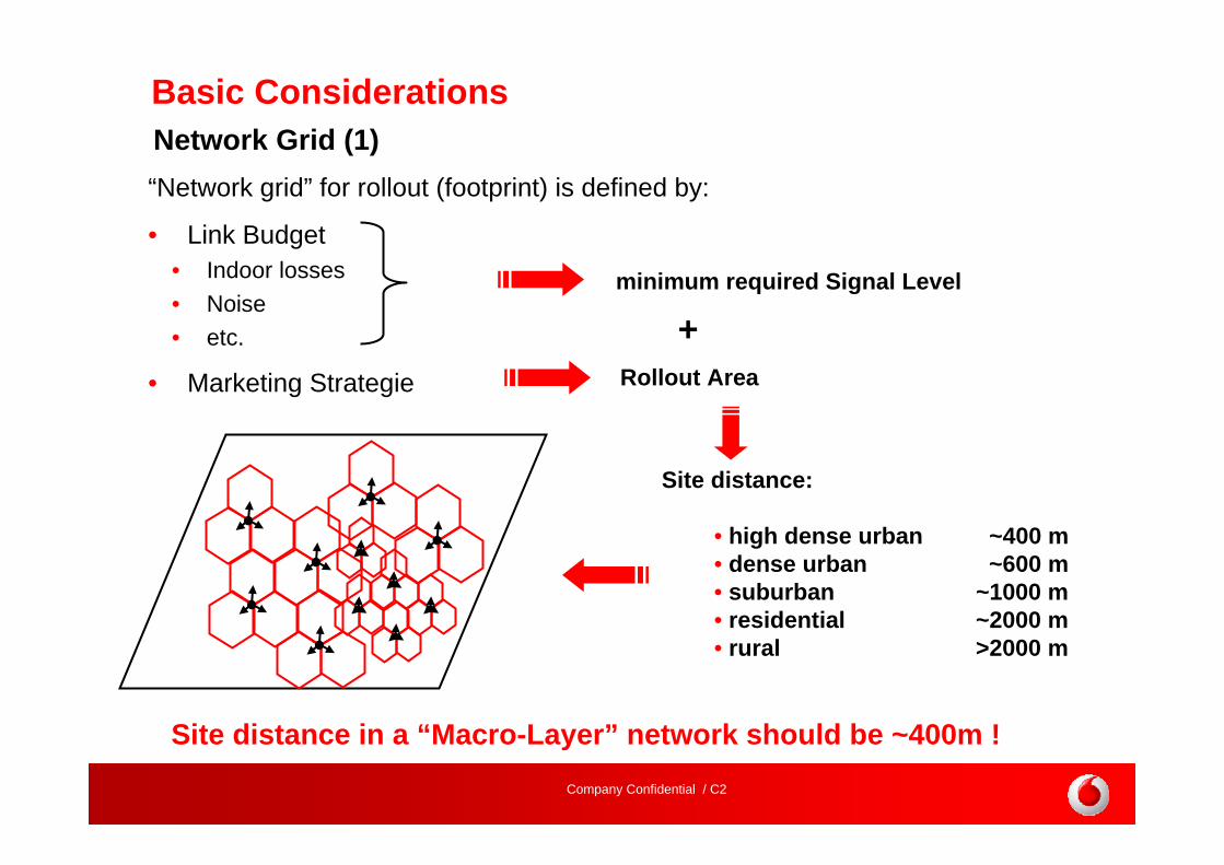
“Network grid” for rollout (footprint) is defined by:
• Link Budget • Indoor losses• Noise• etc.
• Marketing Strategie
minimum required Signal Level
Rollout Area
Site distance:
• high dense urban ~400 m• dense urban ~600 m• suburban ~1000 m• residential ~2000 m• rural >2000 m
+
Network Grid (1)
Site distance in a “Macro-Layer” network should be ~400m !

Company Confidential / C2
Basic ConsiderationsNetwork rollout (1)
Network design should be based on homogenous network!(e.g. acquisition problems / construction limitations will lead to variations)
Assumption: shortest required (possible) site distance is ~600m
final Grid by FY xx+n/yy+n
d = x * ~600m; x=1,2,3,…
~600m ~600m ~600m
Starting Grid by FY xx/yy (Phase 1)
~1800m ~800m
~600m
Grid by FY xx /yy (Phase 2/3)
~1200m ~400m ~400m Huge overlapping / interference!Micro CellInbuilding Solution (Hot Spot Solution)

Company Confidential / C2
Basic ConsiderationsNetwork rollout (2)
GSM
UMTS UMTS
GSM
UMTS Phase 1UMTS Phase 1
UMTS Phase 1
UMTS Phase 2
UMTS Phase 2
GSM
UMTS
GSM
UMTS
high signalling load because of “Island-Sites”
reduced signalling load due to “Cluster”
Cluster based rollout reduces signalling between 2G/3G!
Phase 1Phase 2
Company Confidential / C2
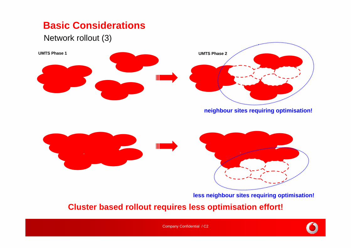
Basic ConsiderationsNetwork rollout (3)
UMTS Phase 1
Cluster based rollout requires less optimisation effort!
UMTS Phase 2
neighbour sites requiring optimisation!
less neighbour sites requiring optimisation!

Company Confidential / C2
Basic Considerations
GSM
“Hard Handover”Mobile connected to only one BTS
Overlapping area has impact on network quality and capacity!
Avoid transmitter directed to each other !
UMTS
“Soft Handover”Mobile connected to several Node Bs
Site / Transmitter Configuration (1)
Company Confidential / C2
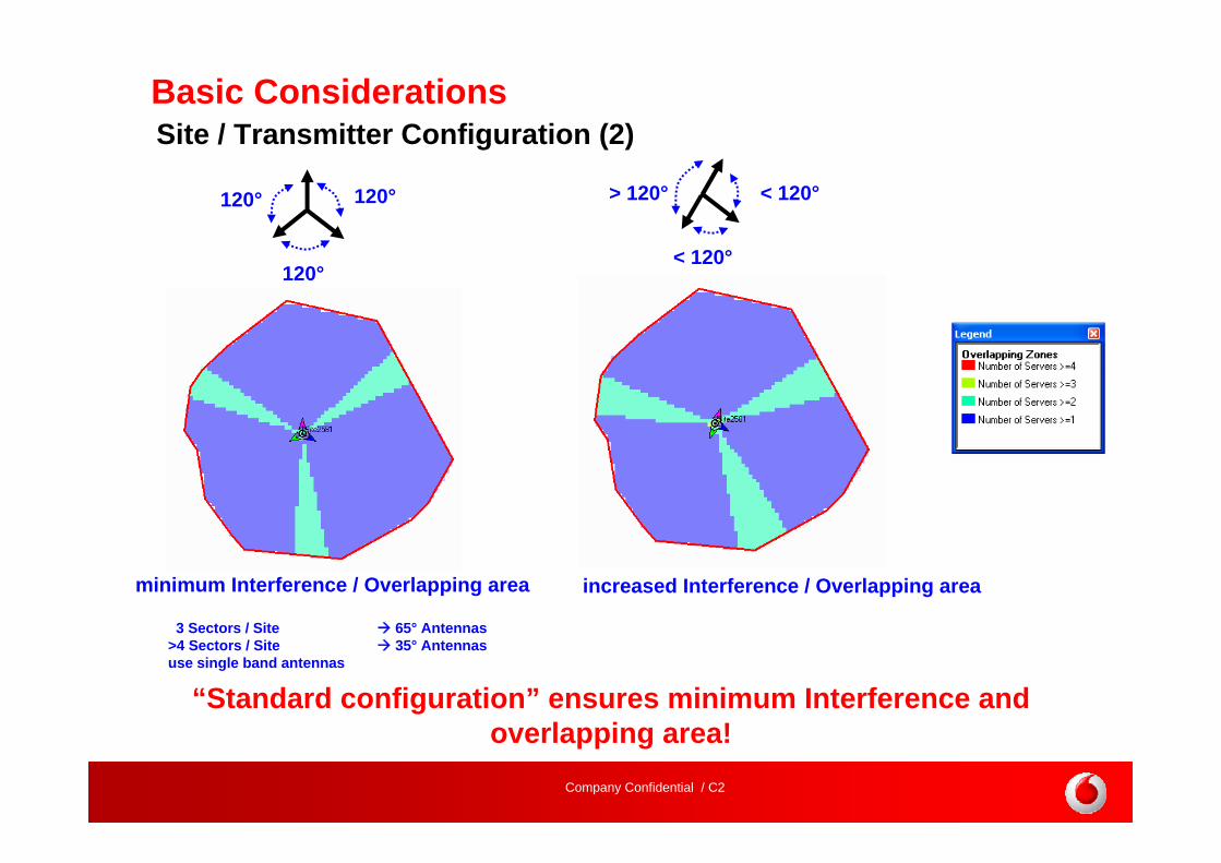
Basic ConsiderationsSite / Transmitter Configuration (2)
120°
120°
120° < 120°
< 120°
> 120°
“Standard configuration” ensures minimum Interference and overlapping area!
minimum Interference / Overlapping area increased Interference / Overlapping area
3 Sectors / Site 65° Antennas>4 Sectors / Site 35° Antennasuse single band antennas

Company Confidential / C2
Basic ConsiderationsSite / Transmitter Configuration (3)
Implement sites with “Optimisation-Space” within further rollout!
10°5°
5° 7°9° 10°
8°
Optimisation for both sites possible
Optimisation only for new site possible
Antenna: XPol F-Panel1720-2170 MHz65°15,5 dBi0° - 10° T
required: 10° Downtilt
implement: 5° mech. Downtilt+
5 ° electr. Downtilt
5° optional Downtilt

Company Confidential / C2
Basic ConsiderationsOptimisation (1)
Optimisation in practice should consider wider area!Optimisation should be done in steps / iterations!
1. Downtilt 2. Azimuth 3. add new Site
covered area
area requiringoptimisation
covered area
analysisarea
computation zone
area requiring optimisation, is optimised within analysis area, considering sites within computationzone

Company Confidential / C2
Basic ConsiderationsOptimisation (2)
covered area covered area
analysis area
computation zone
optimised area
optimise wholearea in steps bymoving areas
Optimise huge areas in steps based on analysis areas and computation zones!
Company Confidential / C2
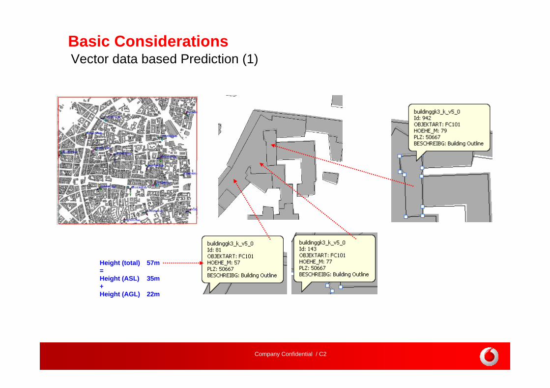
Basic ConsiderationsVector data based Prediction (1)
Height (total) 57m=Height (ASL) 35m+Height (AGL) 22m

Company Confidential / C2 13
Basic Considerations
Single pole
Antennas placed on rooftop / wall mounteAntennas placed on rooftop / wall mounted
Use DX(m) / DY(m) to place distributed antennas / transmitters!
Vector data based Prediction (2)

Company Confidential / C2 14
Basic Considerations
Use DX(m) / DY(m) to place distributed antennas / transmitters!
move / place transmitter on the map
update DX / DY in the transmitter properties
update DX / DY in the transmitter table
Vector data based Prediction (3)
DX (m) move position
DY (m)
change azimuth

Company Confidential / C2 15
Basic Considerations
Prediction based on Vector dataPrediction based on Raster data
Transmitter:K 742264, 65°350°TN, 0° eDTheight 12m
buildings > 20m“Micro Cell”
Microcell or “Wall mounted antenna” prediction should be based on a propagation model using Vector data!
Vector data
based Prediction (4)
Company Confidential / C2
Don’ts of UMTS
1. NO boomer sites for UMTS (sites with height farabove average antenna heights)
In GSM network boomer sites or umbrella sites can be use if these get a special frequency
In UMTS every cell is transmitting on the same frequency=> Boomer sites will cause a lot of interference=> Performance of the neighboured cells is reduced=> Total capacity of affected cluster is reduced
2. Avoidance of antennas of neighbour cells “looking”each directly to the other
3. Avoidance of sectors with separation < 2x beamwidth

Company Confidential / C2
Co-location of UMTS on existing GSM sites
Benefits of Co-location
• Less civil works => reduced CAPEX• Less rental costs => reduced OPEX• Faster rollout possible
The aim should be 100 % co-location of UMTS on GSM sites Realistic value for co-location rate: 90%
ChallengeDecision needed if shared or separate antennas should beused because optimal antenna directions may differ in UMTS and GSM
Company Confidential / C2
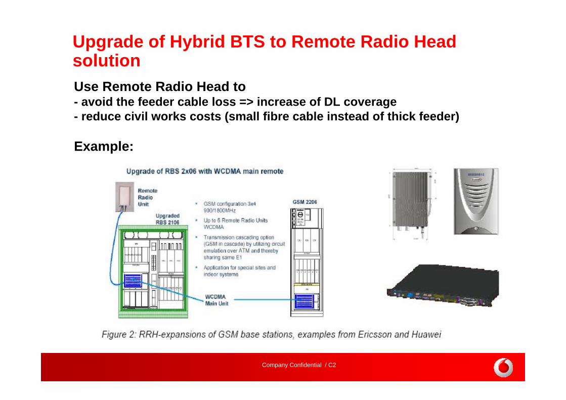
Upgrade of Hybrid BTS to Remote Radio Head solutionUse Remote Radio Head to- avoid the feeder cable loss => increase of DL coverage- reduce civil works costs (small fibre cable instead of thick feeder)
Example:

Company Confidential / C2
Antennas for UMTS
65° beam width for UMTS antennas in a 3 sector configuration
For UMTS on 2100 MHz antennas of the same size have around 3 dB more gain than antennas for 900 MHz
Horizontal pattern Vertical pattern
65o

Company Confidential / C2
Antenna solution with separated antennas for UMTS and GSM

Company Confidential / C2
Antenna solution with shared antennas for UMTS and GSM

Company Confidential / C2
Antennawith
remotecontrolledelectricalDowntilt
Control tilting
in severalsteps
Control tilting
in severalsteps
Node BNode B
Antennawith
remote-controlledelectricalDowntilt
Purpose: adjusting coverage areas including soft handover areasdecreasing of inter-cell interference-improving capacity
Motivation and purpose for RET feature
Company Confidential / C2
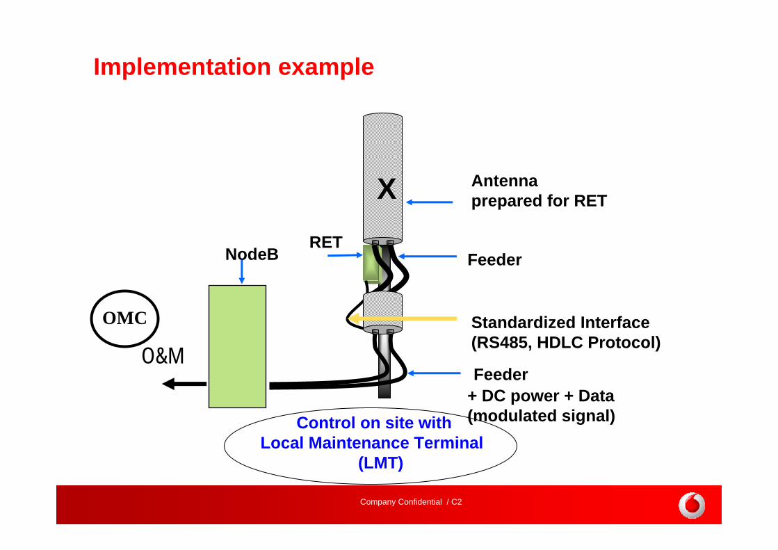
Antennaprepared for RET
Feeder + DC power + Data (modulated signal)
Feeder
Standardized Interface (RS485, HDLC Protocol)
RETNodeB
X
O&M
Implementation example
OMC
Control on site withLocal Maintenance Terminal
(LMT)

Company Confidential / C2
RET System from Ericsson as example
RET UnitDouble DualDuplexAntenna SystemController

Company Confidential / C2
Full control of antennas from network management system
Evolution for automated tilt control based on traffic measures
Vision: Post processing and periodical change

Company Confidential / C2
GSM site preparation for 3GNew GSM sites should be prepared for 3G in areas, where 3G deployment isplanned for the future
- Site contracts should have options for 3G deployment
- Equipment room should have enough floorspace for 3G
- Air conditioning and power supply should be dimensioned for 3G
- Space for 3G antennas should be available or dual/triple band antennas
should be installed
- TMA or Remote Radio Head for 3G should be considered
- Micro wave equipment should be dimensioned for 3G

Company Confidential / C2
Deployment of 3G In-fill solutions

Company Confidential / C2
In-Fill Solutionsoverview of technical options that have been considered
New Macro Sites
• Macro 2.1 GHz with 3 Sectors (Reference)
• Macro 2.1 GHz with 1 or 2 Sectors
• Macro 2.1 GHz with 4-Way Receive Diversity and 40W PA
• Macro 2.1 GHz with 6 Sectors and 20W PA
• Macro 900 MHz with 3 Sectors
Upgrades and expansions of existing UMTS sites
• 4-Way Receive Diversity (modification)
• 6 Sectorisation (modification)
• UMTS 900 MHz (additional carrier and HW)
Other new site solutions
• Micro Node B site
• Dedicated Indoor Coverage System using small DAS (2 floor office building)
• Outdoor Repeater

Company Confidential / C2
Recommended Solution
Trafficdensity
Gap Size [km²]
low
high
0,01 0,05 0,25 0,5 1 5 10
IndoorSolution
Node B upgrade
to 4 WRXD
OutdoorRepeater
MicroNode B
Macro1 Sector
Macro3 Sectors
Macro 3 Sectors& 4 WRXD
Macro6 SectorsMacro
2 Sectors
Rep
eate
rN
ode
B
Solu
tion Wide Area DAS
Only recommended for special cases

Company Confidential / C2
Standard Macro Node BMacro Node B with 4 Way RXD UMTS900 Macro Node B
Coverage Gain of 4 Way RXD or UMTS900 Example 1 Example 2
Example 3

Company Confidential / C2
The size of additional coverage is approximately the same for 4Way RXD and 6 sector site,but the shape of the additional coverage area is different
6 Sector Node B Macro Node B with 4 Way RXD
Comparison of 4 Way RXD and 6 Sector Site
Company Confidential / C2
Micro Cell Solutions
Company Confidential / C2
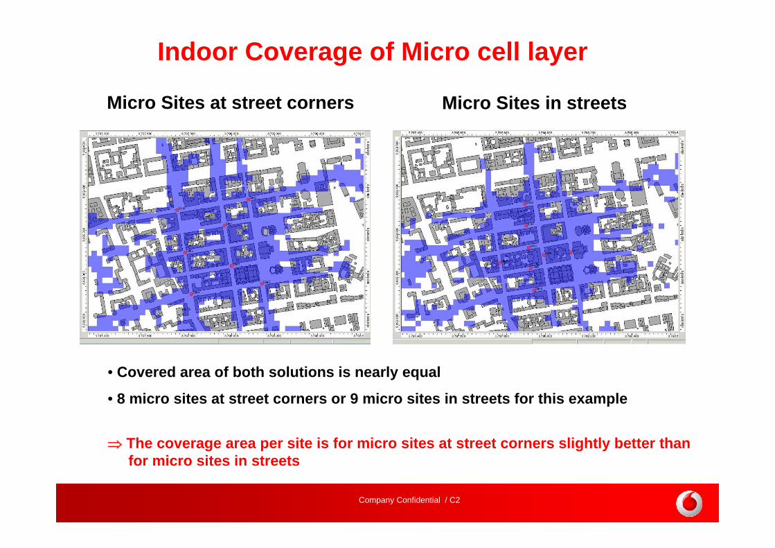
• Covered area of both solutions is nearly equal
• 8 micro sites at street corners or 9 micro sites in streets for this example
⇒ The coverage area per site is for micro sites at street corners slightly better thanfor micro sites in streets
Indoor Coverage of Micro cell layer
Micro Sites at street corners Micro Sites in streets
Company Confidential / C2
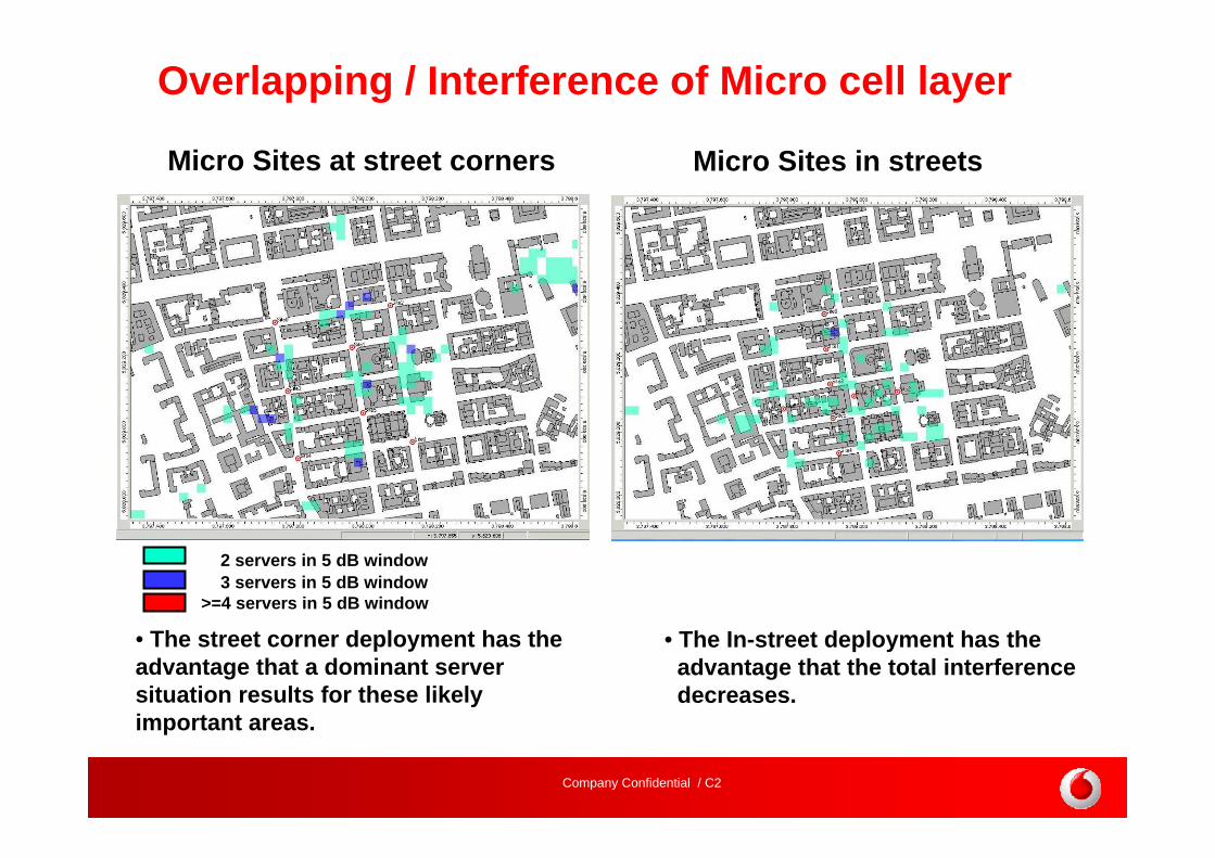
2 servers in 5 dB window3 servers in 5 dB window
>=4 servers in 5 dB window
Overlapping / Interference of Micro cell layer
Micro Sites at street corners Micro Sites in streets
• The street corner deployment has the advantage that a dominant server situation results for these likely important areas.
• The In-street deployment has the advantage that the total interference decreases.
Company Confidential / C2
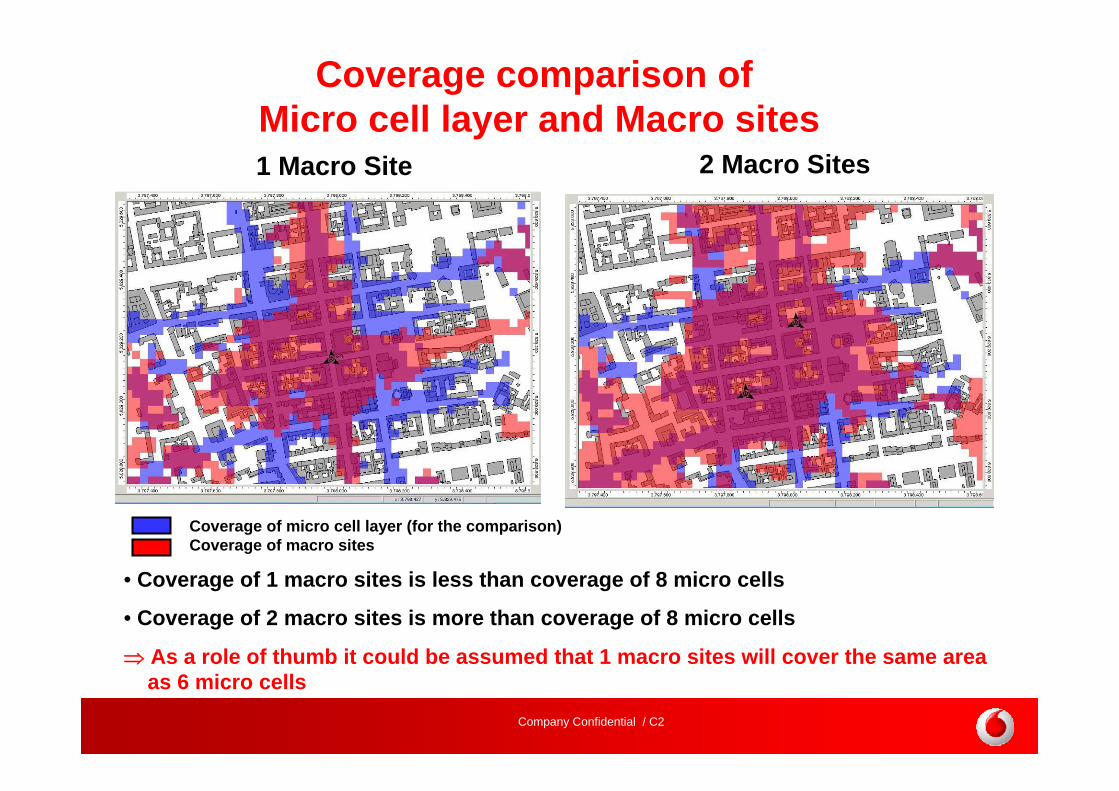
Coverage of micro cell layer (for the comparison) Coverage of macro sites
Coverage comparison of Micro cell layer and Macro sites1 Macro Site 2 Macro Sites
• Coverage of 1 macro sites is less than coverage of 8 micro cells
• Coverage of 2 macro sites is more than coverage of 8 micro cells
⇒ As a role of thumb it could be assumed that 1 macro sites will cover the same area as 6 micro cells

Company Confidential / C2
• Small /medium coverage gaps
• Coverage gaps in a street
• High traffic demand assumed in the area of the coverage gap
• If coverage of the backside of the buildings is of less importance
existing coverage new coverage of a micro cell
Example of micro cell deployment
The deployment of single micro cells is recommended for:

Company Confidential / C2
Dedicated Indoor Solutions

Company Confidential / C2
• Coverage hole is small, but high/medium traffic demand is assumed for this area
• The coverage hole as such is completely made up of a building or building complex.
• Buildings should be public (e.g. Train station, shopping mall, etc.) or business/ industrial area (e.g. office, factories, etc.)
Dedicated Indoor SolutionIn case the coverage hole is limited to one building.
Dedicated indoor coverage solutions should be deployed if:

Company Confidential / C2
Outdoor Repeater Deployment

Company Confidential / C2
Outdoor Repeater DeploymentIn case a coverage hole is an area with lower traffic expectation
New coverage of repeater and donor Node B
existing coverage
Outdoor Repeater
• Coverage extension (indoor and outdoor)• Improve network quality (improve throughput of HSDPA) • Shape of handover area• Reduce pilot pollution areas• Improve DL power management • Temporary solutions
Repeaters can be used for

Company Confidential / C2
Filling coverage holes without new sites

Company Confidential / C2
4 Way Receive Diversity Existing Coverage Upgrade of 3 Node Bs to 4 Way RXD
The coverage holes are usually in the border areas between the cells, therefore 3 or more cells have to be upgraded to close the hole

Company Confidential / C2
UMTS 900 Layer
• Coverage holes with less than 0,3 km² can be closed.


![[XLS] · Web viewQ-OFFSET1-UMTS-MACRO X_UBIQUISYS_COM_Qoffset2UMTSMacro SIntrasearch SIntersearch SSearchRAT CELL-SELECTION-SSEARCHRAT UETxPwrMaxRACH UETX-PWR-MAX-RACH X_UBIQUISYS_COM_PollPeriod](https://img.dokumen.tips/doc/110x75/5b0aa77f7f8b9aba628c8150/xls-viewq-offset1-umts-macro-xubiquisyscomqoffset2umtsmacro-sintrasearch-sintersearch.jpg)