Embed Size (px)
Citation preview
NTF-515 OPERATION MANUAL
MAHLE Aftermarket Inc., Service Solutions 10 Innovation Drive
York, Pennsylvania 17402 USA
Phone: 717-840-0678
Toll Free: 800-468-2321
Website: www.servicesolutions.mahle.com
Manual P/N: 035-82179-00
1
TABLE OF CONTENTS
Pictograms 3
Health, Safety and Environmental Aspects ...................... 3
Description of the NTF-515 Membrane 4
Process Parameters 5
Unpack & Check Equipment 6
Safety Precautions 6
Operation 7
Nitrogen Purity Selection 7
Automatic Tire Filling 8
Manual Single Tire Vacuum and Fill 10
Testing Nitrogen Purity 11
Maintenance 12
Trouble Shooting Guide 14
Parts Identification and Maintenance Parts 15
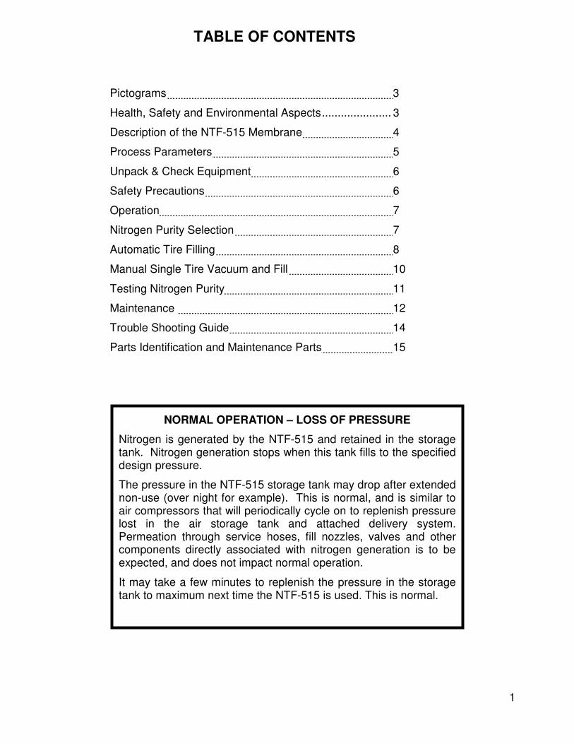
NORMAL OPERATION – LOSS OF PRESSURE
Nitrogen is generated by the NTF-515 and retained in the storage tank. Nitrogen generation stops when this tank fills to the specified design pressure.
The pressure in the NTF-515 storage tank may drop after extended non-use (over night for example). This is normal, and is similar to air compressors that will periodically cycle on to replenish pressure lost in the air storage tank and attached delivery system. Permeation through service hoses, fill nozzles, valves and other components directly associated with nitrogen generation is to be expected, and does not impact normal operation.
It may take a few minutes to replenish the pressure in the storage tank to maximum next time the NTF-515 is used. This is normal.

2
NOTES
3
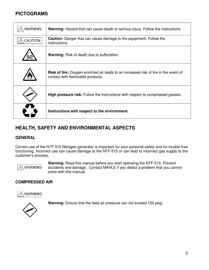
PICTOGRAMS
Warning: Hazard that can cause death or serious injury. Follow the instructions.
Caution: Danger that can cause damage to the equipment. Follow the instructions.
Warning: Risk of death due to suffocation.
Risk of fire: Oxygen-enriched air leads to an increased risk of fire in the event of contact with flammable products.
High pressure risk: Follow the instructions with respect to compressed gasses.
Instructions with respect to the environment.
HEALTH, SAFETY AND ENVIRONMENTAL ASPECTS GENERAL Correct use of the NTF-515 Nitrogen generator is important for your personal safety and for trouble-free functioning. Incorrect use can cause damage to the NTF-515 or can lead to incorrect gas supply to the customer’s process.
Warning: Read this manual before you start operating the NTF-515. Prevent accidents and damage. Contact MAHLE if you detect a problem that you cannot solve with this manual.
COMPRESSED AIR
Warning: Ensure that the feed air pressure can not exceed 150 psig.
4
NITROGEN AND OXYGEN The NTF-515 generates nitrogen as a product. Oxygen enriched air is released as waste.
Warning
Nitrogen can cause suffocation. Oxygen enriched air leads to increased risk of fire in the event of contact with flammable products. Make sure that there is adequate ventilation at all times!
Do not install the NTF-515 in an area where explosive substances may be present.
DESCRIPTION OF THE NTF-515 MEMBRANE GENERAL The NTF-515 separates compressed air into nitrogen and an oxygen enriched air stream. The separation system is based on membrane technology. The compressed air comes from a central system or from a dedicated compressor.
The nitrogen produced is stored in the nitrogen storage vessel. The NTF-515 then switches on and off, depending on the nitrogen demand.
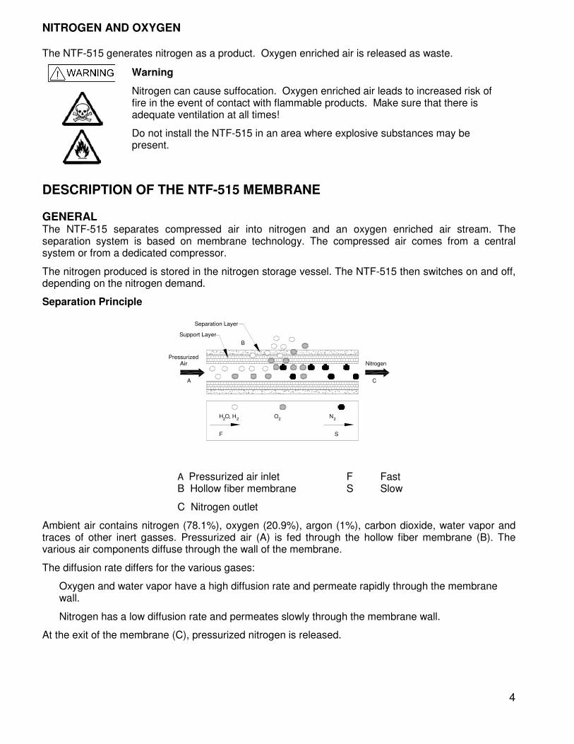
Separation Principle
H O, H2 2
O2
N2
F S
PressurizedAir Nitrogen
A C
B
Support Layer
Separation Layer
A Pressurized air inlet F Fast B Hollow fiber membrane S Slow
C Nitrogen outlet
Ambient air contains nitrogen (78.1%), oxygen (20.9%), argon (1%), carbon dioxide, water vapor and traces of other inert gasses. Pressurized air (A) is fed through the hollow fiber membrane (B). The various air components diffuse through the wall of the membrane.
The diffusion rate differs for the various gases:
Oxygen and water vapor have a high diffusion rate and permeate rapidly through the membrane wall.
Nitrogen has a low diffusion rate and permeates slowly through the membrane wall.
At the exit of the membrane (C), pressurized nitrogen is released.
5
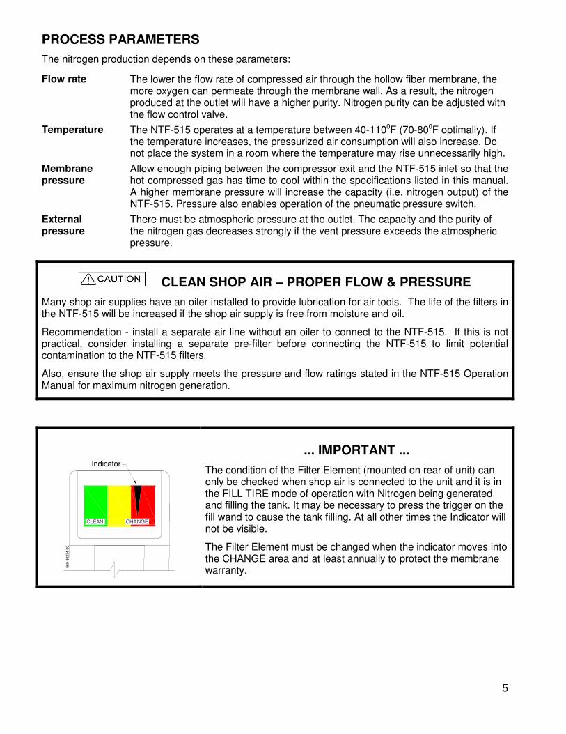
PROCESS PARAMETERS
The nitrogen production depends on these parameters:
Flow rate The lower the flow rate of compressed air through the hollow fiber membrane, the more oxygen can permeate through the membrane wall. As a result, the nitrogen produced at the outlet will have a higher purity. Nitrogen purity can be adjusted with the flow control valve.
Temperature The NTF-515 operates at a temperature between 40-1100F (70-800F optimally). If the temperature increases, the pressurized air consumption will also increase. Do not place the system in a room where the temperature may rise unnecessarily high.
Membrane pressure
Allow enough piping between the compressor exit and the NTF-515 inlet so that the hot compressed gas has time to cool within the specifications listed in this manual. A higher membrane pressure will increase the capacity (i.e. nitrogen output) of the NTF-515. Pressure also enables operation of the pneumatic pressure switch.
External pressure
There must be atmospheric pressure at the outlet. The capacity and the purity of the nitrogen gas decreases strongly if the vent pressure exceeds the atmospheric pressure.
CLEAN SHOP AIR – PROPER FLOW & PRESSURE
Many shop air supplies have an oiler installed to provide lubrication for air tools. The life of the filters in the NTF-515 will be increased if the shop air supply is free from moisture and oil.
Recommendation - install a separate air line without an oiler to connect to the NTF-515. If this is not practical, consider installing a separate pre-filter before connecting the NTF-515 to limit potential contamination to the NTF-515 filters.
Also, ensure the shop air supply meets the pressure and flow ratings stated in the NTF-515 Operation Manual for maximum nitrogen generation.
CLEAN CHANGE
Indicator
56
0-8
037
4-0
0
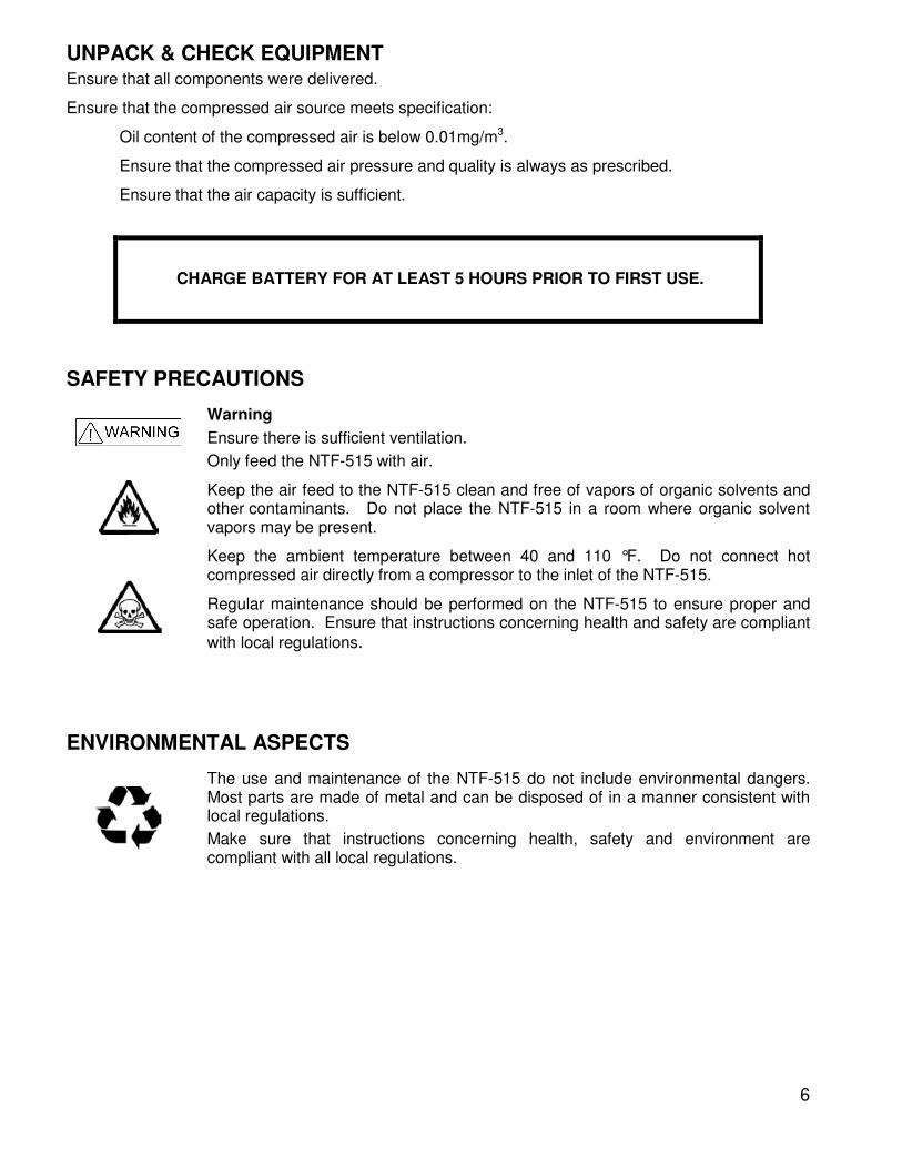
... IMPORTANT ...
The condition of the Filter Element (mounted on rear of unit) can only be checked when shop air is connected to the unit and it is in the FILL TIRE mode of operation with Nitrogen being generated and filling the tank. It may be necessary to press the trigger on the fill wand to cause the tank filling. At all other times the Indicator will not be visible.
The Filter Element must be changed when the indicator moves into the CHANGE area and at least annually to protect the membrane warranty.
6
UNPACK & CHECK EQUIPMENT
Ensure that all components were delivered.
Ensure that the compressed air source meets specification:
Oil content of the compressed air is below 0.01mg/m3.
Ensure that the compressed air pressure and quality is always as prescribed.
Ensure that the air capacity is sufficient.
CHARGE BATTERY FOR AT LEAST 5 HOURS PRIOR TO FIRST USE.
SAFETY PRECAUTIONS
Warning
Ensure there is sufficient ventilation.
Only feed the NTF-515 with air.
Keep the air feed to the NTF-515 clean and free of vapors of organic solvents and other contaminants. Do not place the NTF-515 in a room where organic solvent vapors may be present.
Keep the ambient temperature between 40 and 110 °F. Do not connect hot compressed air directly from a compressor to the inlet of the NTF-515.
Regular maintenance should be performed on the NTF-515 to ensure proper and safe operation. Ensure that instructions concerning health and safety are compliant
with local regulations.
ENVIRONMENTAL ASPECTS
The use and maintenance of the NTF-515 do not include environmental dangers. Most parts are made of metal and can be disposed of in a manner consistent with local regulations.
Make sure that instructions concerning health, safety and environment are compliant with all local regulations.
7
OPERATION
FOREIGN SUBSTANCES IN TIRES
Tires which have been in service may contain foreign substances such as leak sealers. It is important that these substances are not pulled into the NitroPro unit during the vacuum procedure, resulting in possible performance issues and costly repairs not covered by MAHLE’s warranty.
When servicing a vehicle, first check the valve stems and valve stem caps for any type of fluid or foreign substance. Install deflators and allow all four tires to deflate to zero pressure. Then check the deflators for any indication of fluids or foreign substances.
Do not use the NitroPro vacuum procedure on any tire where evidence of fluids or foreign substances are detected on the valve stems, valve stem caps or deflators. Instead, follow a four step “deflate-inflate-deflate-inflate” process to achieve desired nitrogen purity.
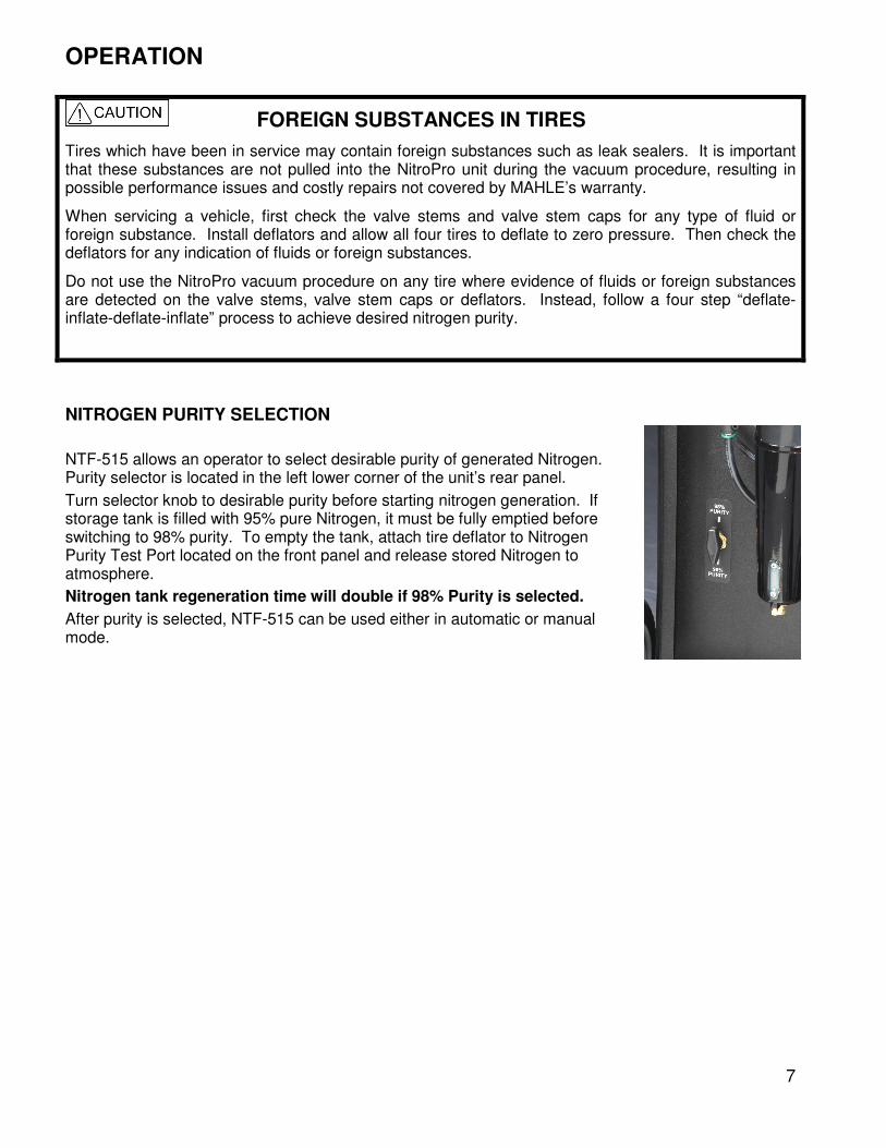
NITROGEN PURITY SELECTION
NTF-515 allows an operator to select desirable purity of generated Nitrogen. Purity selector is located in the left lower corner of the unit’s rear panel.
Turn selector knob to desirable purity before starting nitrogen generation. If storage tank is filled with 95% pure Nitrogen, it must be fully emptied before switching to 98% purity. To empty the tank, attach tire deflator to Nitrogen Purity Test Port located on the front panel and release stored Nitrogen to atmosphere.
Nitrogen tank regeneration time will double if 98% Purity is selected.
After purity is selected, NTF-515 can be used either in automatic or manual mode.

8
AUTOMATIC TIRE FILLING
PURGE/FILL AND TOP OFF CYCLES
1. Attach air supply (150 PSI max) to the unit.
2. Turn both valve knobs to FILL TIRE. Verify pressure indicated on AIR PRESSURE gauge is between 120 - 150 PSI.
3. Allow unit to build pressure in Nitrogen storage tank as shown on N2 PRESSURE gauge (120 PSI).
4. Turn on POWER switch on the top of control panel. PCB will display battery charge status (HI or LO). Ensure that 12VDC battery is charged. See section on Battery charging for more information.
5. Connect hoses to tires. NTF-515 unit is equipped with four service hoses, coiled on both sides. 12 FT long hoses should be connected to tires, nearest to the operator. 24 FT long hoses should be connected to farthest tires on the vehicle. Ensure that air chucks are fully engaged with valve stems for proper service.
6. Set the final target pressure by pressing + or – buttons.
7. To change Over Pressure and Nitrogen Purge Cycles settings see following sections.
8. Press and hold START button for two seconds (until long beep). This will start Nitrogen Purge Cycle. For Top Off cycle press START button momentarily and release it. Top Off cycle will start immediately.
One complete Nitrogen Purge Cycle will deflate all tires to 10% of target pressure (approximately 3 PSI for 30 PSI target), inflate to target pressure, deflate to 50% of target pressure then inflate to final target pressure. (If two or more Purge Cycles are programmed the above process will be repeated).
9. Unit will beep at the end of service and word END will appear on LCD.
10. It’s recommended to wait 10-15 seconds after the end of service before disconnecting hoses.
11. Press any key to stop process.
9
TOP OFF AND NITROGEN PURGE CYCLE COUNTER
NTF-515 will total the number of Top Offs and Nitrogen Purge Cycles performed.
1. Press and hold + and - buttons simultaneously until unit beeps.
2. Press + or – button.
3. First displayed number shows thousands of Top Offs.
4. Press + or - button. Hundreds, tens and ones of Top Offs will be displayed.
5. Press + or - button. Thousands of Nitrogen Purge Cycles will be displayed.
6. Press + or - button. Hundreds, tens and ones of Nitrogen Purge Cycles will be displayed.
7. Press + or - button to exit counter mode.
OVER PRESSURE SETTING (OPS) AND NITROGEN PURGE CYCLES (N2P)
The Over Pressure Setting can be used to improve the purity of the tire(s). The Over Pressure Setting over inflates the target pressure on the first inflation by the OPS amount. For example, if the OPS is set at 5 PSI and the initial target pressure is set to 30 PSI, then the N2P will deflate to 3 PSI, inflate to 35 PSI, deflate to 15 PSI, then inflate to 30 PSI. Inflating to 35 PSI during the first inflation instead of 30 PSI will result in higher nitrogen purity in the tires.
The number of Nitrogen Purge Cycles can be set. One Nitrogen Purge Cycles consists of deflating, inflating, deflating to 50% of the target pressure, and inflating to the target pressure. This entire process can be automatically repeated by changing the number of Nitrogen Purge
Cycles. This will result in higher nitrogen purity in the tires.
1. Turn POWER switch on.
2. Press N2 button once.
3. Press + or – buttons to change the Over Pressure Setting.
4. Press START button to save the Over Pressure Setting.
5. Press N2 button.
6. Press + or – buttons to select desirable number of Nitrogen Purge Cycles.
7. Press START button to save the number of Nitrogen Purge Cycles.
When unit is turned off, it will save the changed settings until they are changed again.
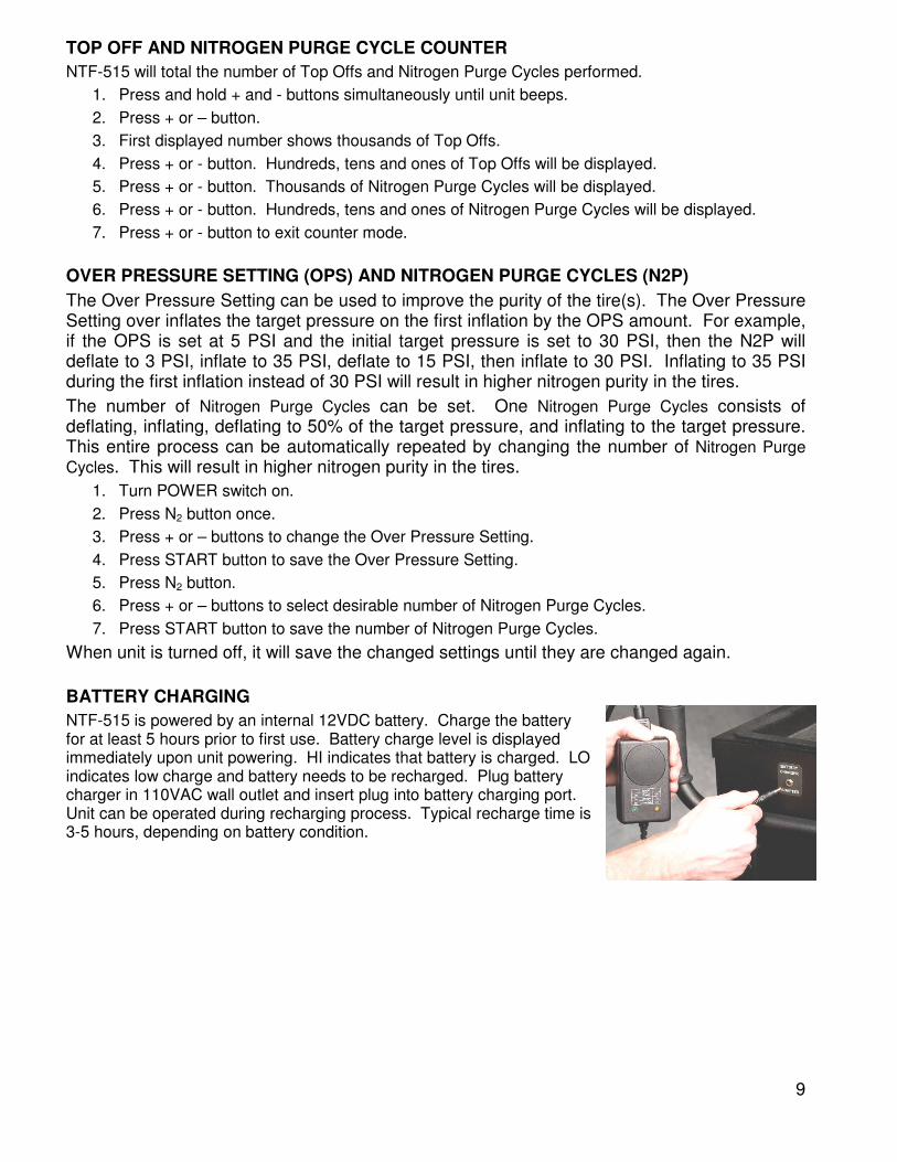
BATTERY CHARGING
NTF-515 is powered by an internal 12VDC battery. Charge the battery for at least 5 hours prior to first use. Battery charge level is displayed immediately upon unit powering. HI indicates that battery is charged. LO indicates low charge and battery needs to be recharged. Plug battery charger in 110VAC wall outlet and insert plug into battery charging port. Unit can be operated during recharging process. Typical recharge time is 3-5 hours, depending on battery condition.
10
MANUAL SINGLE TIRE VACUUM AND FILL
VACUUM TIRE
1. Install deflators and check for foreign substances as explained earlier.
2. Connect shop air to the air inlet port on the rear of the NTF-515. Verify pressure indicated on AIR PRESSURE gauge is between 120 - 150 PSI.
3. Turn both panel valves to VACUUM TIRE.
4. Remove deflator and connect Digital Pressure Gauge (on the end of the NTF-515 coiled green hose) to the tire valve stem. Squeeze handle to vacuum the tire. Do not vacuum to a level where the tire starts to deform.
FILL TIRE
1. Connect shop air to the air inlet port on the rear of the NTF-515. Verify pressure indicated on panel mounted Air Pressure gauge is between 120 - 150 PSI. Verify nitrogen pressure indicated on the panel mounted N2 PRESSURE gauge is adequate for service.
2. Turn both panel valves to FILL TIRE.
3. Connect Pressure Gauge (on the end of the NTF-515 coiled green hose) to the tire valve stem. Squeeze handle to fill tire. Periodically release the handle to observe the pressure level. Stop when the pressure reaches the tire manufacturer’s recommended inflation pressure. Do not over inflate.
4. Install an MAHLE N2 Cap (Package of 200 - Part Number 355-80026-00).
Note: While not using the NTF-515 to fill or vacuum tires, generate Nitrogen and increase the Nitrogen pressure in the internal storage tank by turning both panel valves to STANDBY.
Note: While using the NTF-515, the automatic drain feature of the filters may activate to remove excess water and oil. This is normal with the standard operation of the unit.
If your application requires an inlet pressure of 100 - 119 PSI, an adjustment to the automatic pressure switch may be required.
Contact MAHLE Technical Support at 800-468-2321 for further details.
NTF-515 Accuracy
The NTF-515 display has an accuracy of ± 1 PSI. The hand-held gauge (Digital Pressure Gauge) also has an accuracy of ± 1 PSI. Adding the two tolerances means the display gauge and Digital Pressure Gauge could be different by as much as 2 PSI.
When verifying pressure accuracy of the NTF-515, make sure the gauges being used are good quality, calibrated gauges. Low quality pressure gauges, such as “stick” gauges, have an accuracy of ± 2 or 3 PSI, thus pressure differences could be 3 or 4 PSI between these gauges and the display.
11
TESTING NITROGEN PURITY
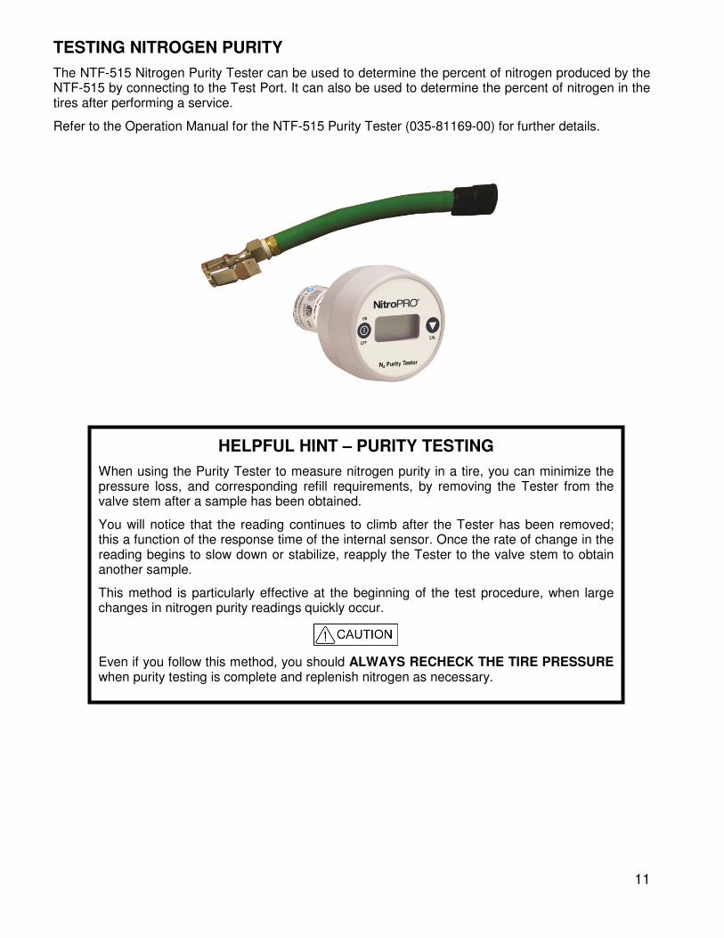
The NTF-515 Nitrogen Purity Tester can be used to determine the percent of nitrogen produced by the NTF-515 by connecting to the Test Port. It can also be used to determine the percent of nitrogen in the tires after performing a service.
Refer to the Operation Manual for the NTF-515 Purity Tester (035-81169-00) for further details.
HELPFUL HINT – PURITY TESTING
When using the Purity Tester to measure nitrogen purity in a tire, you can minimize the pressure loss, and corresponding refill requirements, by removing the Tester from the valve stem after a sample has been obtained.
You will notice that the reading continues to climb after the Tester has been removed; this a function of the response time of the internal sensor. Once the rate of change in the reading begins to slow down or stabilize, reapply the Tester to the valve stem to obtain another sample.
This method is particularly effective at the beginning of the test procedure, when large changes in nitrogen purity readings quickly occur.
Even if you follow this method, you should ALWAYS RECHECK THE TIRE PRESSURE when purity testing is complete and replenish nitrogen as necessary.
12
CLEAN CHANGE
Indicator
560
-803
74
-00
MAINTENANCE
... IMPORTANT ... The condition of the Filter Element (mounted on rear of unit) can only be checked when shop air is connected to the unit and it is in the FILL TIRE mode of operation with Nitrogen being generated and filling the tank. It may be necessary to press the trigger on the fill wand to cause the tank filling. At all other times the Indicator will not be visible.
The Filter Element must be changed when the indicator moves into the CHANGE area and at least annually to protect the membrane warranty.
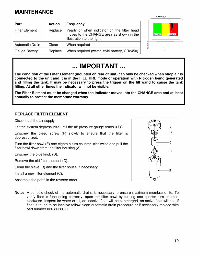
REPLACE FILTER ELEMENT
Disconnect the air supply.
Let the system depressurize until the air pressure gauge reads 0 PSI.
Unscrew the bleed screw (F) slowly to ensure that the filter is depressurized.
Turn the filter bowl (E) one eighth a turn counter- clockwise and pull the filter bowl down from the filter housing (A).
Unscrew the blue knob (D).
Remove the old filter element (C).
Clean the sieve (B) and the filter house, if necessary.
Install a new filter element (C).
Assemble the parts in the reverse order.
Note: A periodic check of the automatic drains is necessary to ensure maximum membrane life. To verify float is functioning correctly, open the filter bowl by turning one quarter turn counter-clockwise. Inspect for water or oil, an inactive float will be submerged, an active float will not. If float is found to be inactive follow clean automatic drain procedure or if necessary replace with part number 026-80386-00.
Part Action Frequency
Filter Element Replace Yearly or when indicator on the filter head moves to the CHANGE area as shown in the illustration to the right.
Automatic Drain Clean When required
Gauge Battery Replace When required (watch style battery, CR2450)
13
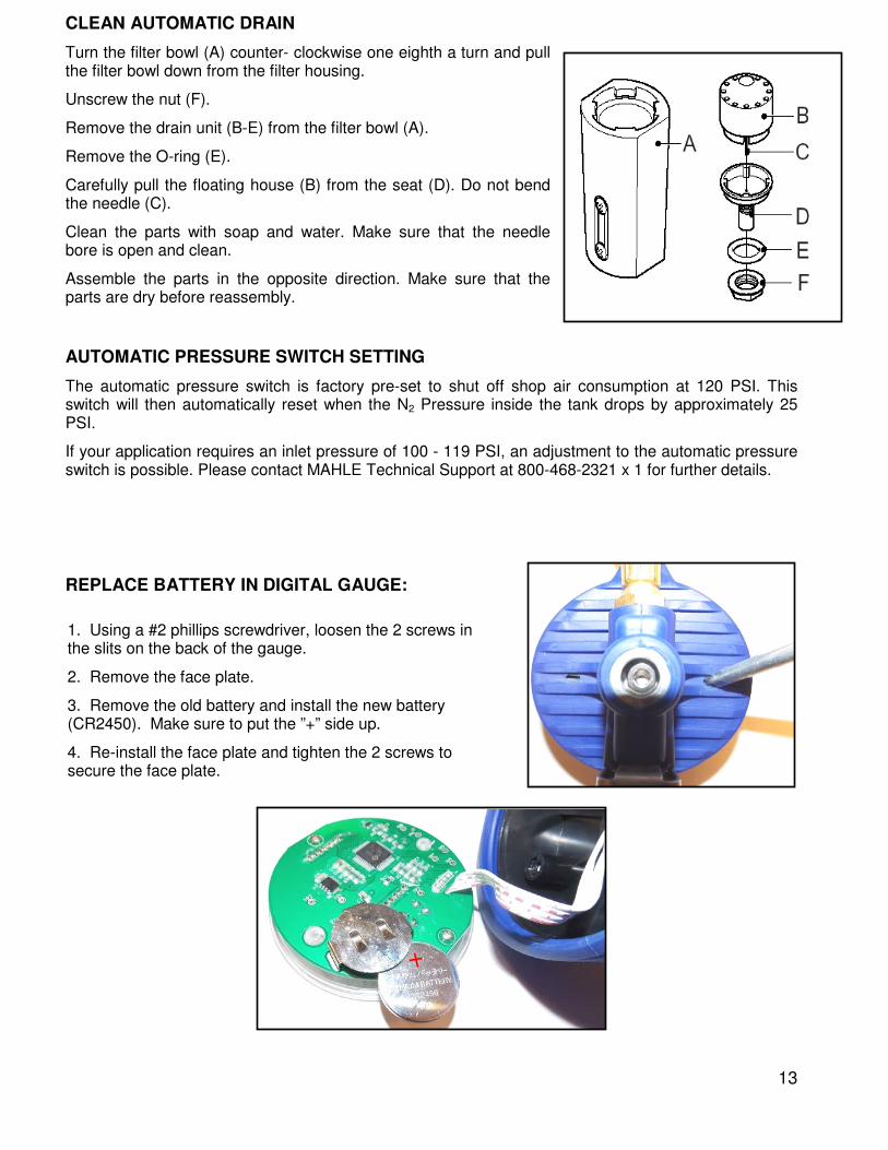
CLEAN AUTOMATIC DRAIN
Turn the filter bowl (A) counter- clockwise one eighth a turn and pull the filter bowl down from the filter housing.
Unscrew the nut (F).
Remove the drain unit (B-E) from the filter bowl (A).
Remove the O-ring (E).
Carefully pull the floating house (B) from the seat (D). Do not bend the needle (C).
Clean the parts with soap and water. Make sure that the needle bore is open and clean.
Assemble the parts in the opposite direction. Make sure that the parts are dry before reassembly.
AUTOMATIC PRESSURE SWITCH SETTING
The automatic pressure switch is factory pre-set to shut off shop air consumption at 120 PSI. This switch will then automatically reset when the N2 Pressure inside the tank drops by approximately 25 PSI.
If your application requires an inlet pressure of 100 - 119 PSI, an adjustment to the automatic pressure switch is possible. Please contact MAHLE Technical Support at 800-468-2321 x 1 for further details.
REPLACE BATTERY IN DIGITAL GAUGE:
1. Using a #2 phillips screwdriver, loosen the 2 screws in the slits on the back of the gauge.
2. Remove the face plate.
3. Remove the old battery and install the new battery (CR2450). Make sure to put the ”+” side up.
4. Re-install the face plate and tighten the 2 screws to secure the face plate.
14
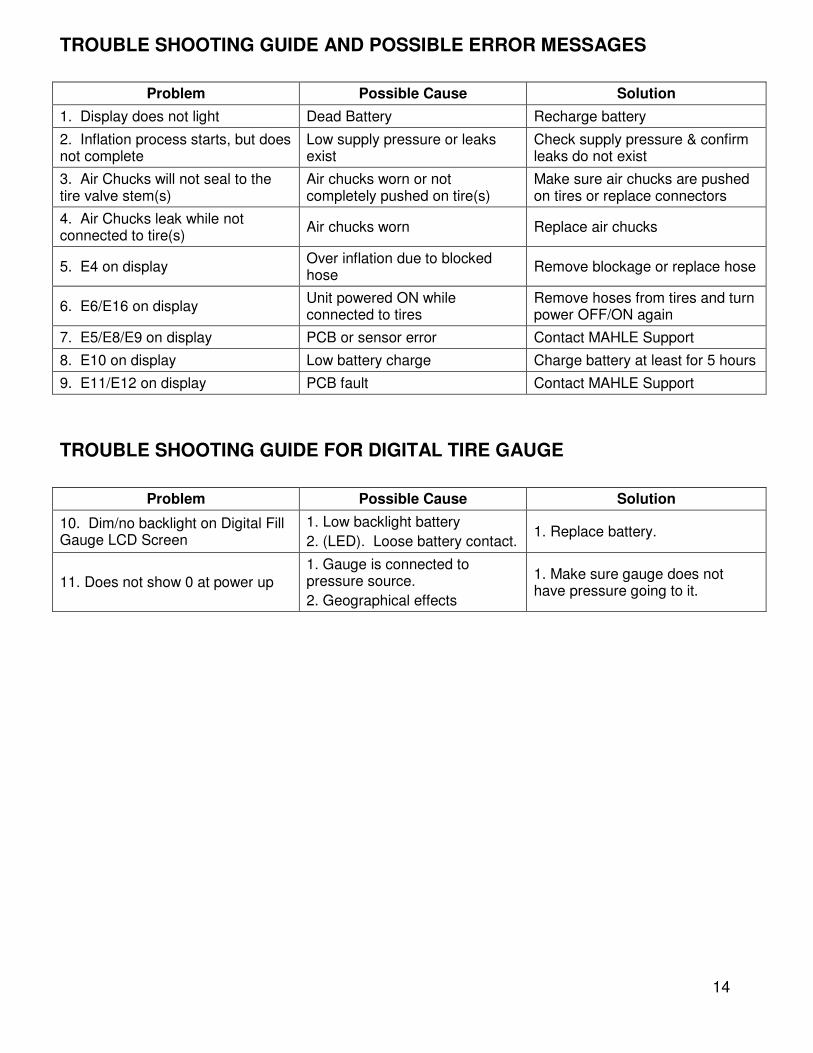
TROUBLE SHOOTING GUIDE AND POSSIBLE ERROR MESSAGES
Problem Possible Cause Solution
1. Display does not light Dead Battery Recharge battery
2. Inflation process starts, but does not complete
Low supply pressure or leaks exist
Check supply pressure & confirm leaks do not exist
3. Air Chucks will not seal to the tire valve stem(s)
Air chucks worn or not completely pushed on tire(s)
Make sure air chucks are pushed on tires or replace connectors
4. Air Chucks leak while not connected to tire(s)
Air chucks worn Replace air chucks
5. E4 on display Over inflation due to blocked hose
Remove blockage or replace hose
6. E6/E16 on display Unit powered ON while connected to tires
Remove hoses from tires and turn power OFF/ON again
7. E5/E8/E9 on display PCB or sensor error Contact MAHLE Support
8. E10 on display Low battery charge Charge battery at least for 5 hours
9. E11/E12 on display PCB fault Contact MAHLE Support
TROUBLE SHOOTING GUIDE FOR DIGITAL TIRE GAUGE
Problem Possible Cause Solution
10. Dim/no backlight on Digital Fill Gauge LCD Screen
1. Low backlight battery
2. (LED). Loose battery contact. 1. Replace battery.
11. Does not show 0 at power up
1. Gauge is connected to pressure source.
2. Geographical effects
1. Make sure gauge does not have pressure going to it.
15
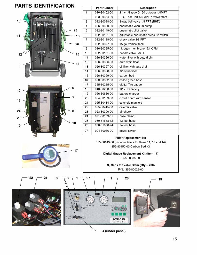
PARTS IDENTIFICATION
Part Number Description
1 026-80452-00 2 inch Gauge 0-160 psig/bar 1/4MPT
2 023-80364-00 FTG Test Port 1/4 MPT X valve stem
3 022-80028-00 3-way ball valve 1/4 FPT (BHD)
4 026-80330-00 pneumatic vacuum pump
5 022-80149-00 pneumatic pilot valve
6 022-80131-00 adjustable pneumatic pressure switch
7 022-80128-00 check valve 3/8 FPT
8 022-80377-00 15 gal vertical tank
9 026-80395-00 nitrogen membrane (5.1 CFM)
10 022-80151-00 needle valve 3/8 FPT
11 026-80396-00 water filter with auto drain
12 026-80386-00 auto drain float
13 026-80397-00 oil filter with auto drain
14 026-80398-00 moisture filter
15 026-80399-00 carbon bed
16 028-80362-00 coiled green hose
17 355-80235-00 digital Tire gauge
18 040-80220-00 12 VDC battery
19 026-80636-00 battery charger
20 024-80139-00 circuit board with sensor
21 025-80414-00 solenoid manifold
22 025-80415-00 diverter valve
23 023-80390-00 air chuck
24 021-80169-01 hose clamp
25 060-81638-12 12 foot hose
26 060-81638-24 24 foot hose
27 024-80066-00 power switch
18
9
5
10
8
7
6
23
24
22 21
25
26
15
14 3
16
12
13 11
Filter Replacement Kit
355-80149-00 (Includes filters for Items 11, 13 and 14)
355-80150-00 Carbon Bed Kit
Digital Gauge Replacement Kit (Item 17)
355-80235-00
N2 Caps for Valve Stem (Qty = 200)
P/N: 355-80026-00
19
17
3 1 2 27 1 20
4 (under panel)

16