Embed Size (px)
DESCRIPTION
hdfh
Citation preview

Physical Layer ConceptsPhysical Layer Concepts
Physical Layer Concepts 2
TopicsTopics1. Multiple Access Approaches2. Code Correlation3. Spread Spectrum Multiple Access (SSMA) Using PN Codes4. Orthogonal Data Channelisation

Physical Layer Concepts 3
Multiple Access ApproachesMultiple Access Approaches
Physical Layer Concepts 4
From 2G to 3GFrom 2G to 3G
Circuit-Switched Voice
Circuit-Switched Data
Short Message Service (SMS)
2G 9.6, 14.4 kbps
Circuit-Switched Voice
Low-Speed Circuit-Switched Data
Packet Data
High-Speed Circuit-Switched Data
3G up to 2 Mbps ?
Physical Layer Concepts 5
Multiple Access ApproachesMultiple Access ApproachesFrequency Division Multiple Access
Each User has a unique frequency
(1 voice channel per user)
All users transmit at the same time
AMPS, NMT, TACS
Each Transmitter has a unique spreading code
Each Data Channel has a uniqueorthogonal code
Many users share the same frequency and time
IS-95, cdma2000, WCDMA
CodeDivision Multiple Access
SpreadSpectrumMultipleAccess
Multiple Transmittersand Data Channels
Each User has a unique time slot
Each Data Channel has a uniqueposition within the time slot
Several users share the same frequency
IS-136, GSM, PDC
Time Division Multiple Access
TIME
FREQUENCY
POWER
TIME
FREQUENCY
POWER
TIME
FREQUENCY
POWER
Physical Layer Concepts 6
Channel CapacityChannel Capacity• In 1948, Claude Shannon of Bell Laboratories
proved the following remarkable formula:
• Capacity measured in bits/second− one bit = yes/no, or on/off, or 0/1
• Bandwidth is in hertz• Signal power and noise power measured
in same units, e.g. watts• Shannon’s result is the best that can ever be achieved—it’s the job
of engineers to design systems which approach this capacity
⎟⎟⎠
⎞⎜⎜⎝
⎛+×=
power noisepower signal1logbandwidthcapacity 2
Claude Shannon (1916—2001)

Physical Layer Concepts 7
CCode Correlationode Correlation
Physical Layer Concepts 8
OrthogonalityOrthogonality and Correlation of Signalsand Correlation of Signals• In communication receivers,
need to quantify the degree to which discrete waveforms or digital symbols 'differ' from one another.
• This can be accomplished by correlation operation
• Two signals s1(t) and s2(t) are said to be orthogonal or in the interval t1 to t2 if:
( ) ( ) 0 2
1
21 =⋅∫ dttstst
t
s (t)1
t0
1 2
1
Signallinginterval, T
t0
1 2
s (t)2
1
-1
-1
( ) ( )dttstsSt
txy 2
1
21∫ ⋅=

Physical Layer Concepts 9
Optimum ReceiversOptimum Receivers• Optimum receivers minimize the probability of making a decision
error by averaging out the noise contribution in the channel− need to make a couple of assumptions, most importantly, channel
noise is additive white Gaussian noise (AWGN)• Optimum receiver must compare received signal with the two known
symbols s0(t) and s1(t)• Optimum detection is therefore a two-stage process:
− a correlator produces a number which indicates how close the received signal r(t) is to s0(t) and s1(t)
− a detector decides which symbol is more likely
×
)(tsn
( )∫T
dt0( )∫
T
dt0
)()( tntr + nr
Sampleat t = T
Correlator hTThreshold
ka
Physical Layer Concepts 10
Correlation ValuesCorrelation Values
( ) ( ) 1 1
0 21 +=⋅∫ dttsts
s (t)1
t0
+1
SignallingInterval, T
t0
s (t)2
+1
-1
-1
0.5 1
0.5 1
( ) ( ) 1 1
0 21 −=⋅∫ dttsts ( ) ( ) 0 1
0 21 =⋅∫ dttsts
s (t)1
t0
+1
SignallingInterval, T
t0
0.5 1
s (t)2
+1
-1
-1
0.5 1
s (t)1
t0
+1
SignallingInterval, T
t0
s (t)2
+1
-1
-10.5 1
0.5 1
Similar Signals Dissimilar Signals Orthogonal Signals
Physical Layer Concepts 11
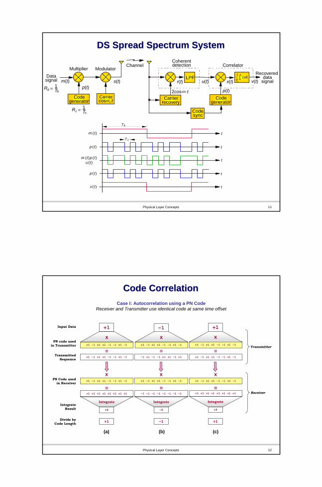
DS Spread Spectrum SystemDS Spread Spectrum System
t
t
t
t
t
m (t)
m (t)p (t)
p (t)
p (t)
x (t)
T c
Tb
u (t)
LPF
Coherentdetection
2cosω t c
Correlator
p(t)
Recovereddata
signalDatasignal m(t)
Rc = 1Tc
Rb = 1Tb
p(t)s(t)
ModulatorMultiplierChannel
r(t) u(t) x(t)dt
TbT
b
)(10∫ v(t)
Codegenerator
Carriercosω t c
Carrierrecovery
Codegenerator
Codesync
Physical Layer Concepts 12
Code CorrelationCode CorrelationCase I: Autocorrelation using a PN Code
Receiver and Transmitter use identical code at same time offset
Input Data +1 -1 +1
+1 -1 +1Divide byCode Length
+1 –1 +1 +1 –1 -1 +1 -1 +1 –1 +1 +1 –1 -1 +1 -1 +1 –1 +1 +1 –1 -1 +1 -1PN code used
in Transmitter
x x x
+8 -8 +8
IntegrateResult
Integrate Integrate Integrate
+1 –1 +1 +1 –1 -1 +1 -1 -1 +1 -1 -1 +1 +1 -1 +1 +1 –1 +1 +1 –1 -1 +1 -1TransmittedSequence
= = =
+1 +1 +1 +1 +1 +1 +1 +1 -1 –1 –1 –1 –1 –1 –1 -1 +1 +1 +1 +1 +1 +1 +1 +1= = =
+1 –1 +1 +1 –1 -1 +1 -1 +1 –1 +1 +1 –1 -1 +1 -1 +1 –1 +1 +1 –1 -1 +1 -1PN Code usedin Receiver
x x x
Transmitter
Receiver
(a) (b) (c)

Physical Layer Concepts 13
Code CorrelationCode CorrelationCase II: Cross-Correlation using PN CodesReceiver and Transmitter use different codes
Input Data +1 -1 +1
+1 –1 +1 +1 –1 -1 +1 -1 +1 –1 +1 +1 –1 -1 +1 -1 +1 –1 +1 +1 –1 -1 +1 -1
+1 –1 +1 +1 –1 -1 +1 -1 -1 +1 -1 -1 +1 +1 -1 +1 +1 –1 +1 +1 –1 -1 +1 -1
-1 +1 –1 +1 +1 –1 -1 +1 +1 -1 +1 –1 +1 +1 –1 -1 -1 +1 +1 +1 –1 -1 +1 +1
-1 –1 –1 +1 –1 +1 –1 -1 -1 –1 –1 +1 +1 +1 +1 -1 -1 –1 +1 +1 +1 +1 +1 -1
PN code usedin Transmitter
TransmittedSequence
PN Code usedin Receiver
-4 0 2
IntegrateResult
-0.5 0 0.25Divide by
Code Length
x x x
Integrate Integrate Integrate
= = =
x x x
= = =
Transmitter
Receiver
(a) (b) (c)
Physical Layer Concepts 14
Code CorrelationCode CorrelationCase III: Correlation using Orthogonal Codes
(a) Same Orthogonal code; (b) Different Orthogonal codes; (c) Same code with non-zero time offset
Input Data +1 -1 +1
-1 +1 –1 +1 +1 –1 +1 -1 -1 +1 –1 +1 +1 –1 +1 -1 -1 +1 –1 +1 +1 –1 +1 -1
-1 +1 –1 +1 +1 –1 +1 -1 +1 –1 +1 –1 –1 +1 –1 +1 -1 +1 –1 +1 +1 –1 +1 -1
-1 +1 –1 +1 +1 –1 +1 -1 +1 +1 +1 +1 +1 +1 +1 +1 -1 -1 +1 –1 +1 +1 –1 +1
+1 +1 +1 +1 +1 +1 +1 +1 +1 –1 +1 –1 –1 +1 –1 +1 +1 –1 –1 –1 +1 –1 –1 -1
Orthogonal codein Transmitter
TransmittedSequence
Orthogonal Codeused in Receiver
8 0 -4
IntegrateResult
+1 0 -0.5Divide byCode Length
x x x
Integrate Integrate Integrate
= = =
x x x
= = =
Transmitter
Receiver
(a) (b) (c)
Physical Layer Concepts 15
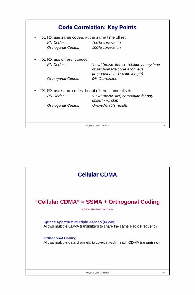
Code Correlation: Key PointsCode Correlation: Key Points• TX, RX use same codes, at the same time offset
− PN Codes: 100% correlation− Orthogonal Codes: 100% correlation
• TX, RX use different codes− PN Codes: “Low” (noise-like) correlation at any time
offset Average correlation level proportional to 1/(code length)
− Orthogonal Codes: 0% Correlation
• TX, RX use same codes, but at different time offsets− PN Codes: “Low” (noise-like) correlation for any
offset > +1 chip− Orthogonal Codes: Unpredictable results
Physical Layer Concepts 16
Cellular CDMACellular CDMA
“Cellular CDMA” = SSMA + Orthogonal Coding(IS-95, cdma2000, WCDMA)
Spread Spectrum Multiple Access (SSMA):Allows multiple CDMA transmitters to share the same Radio Frequency
Orthogonal Coding:Allows multiple data channels to co-exist within each CDMA transmission

Physical Layer Concepts 17
Spread Spectrum Multiple AccessSpread Spectrum Multiple Access(SSMA) Using PN Codes(SSMA) Using PN Codes
Physical Layer Concepts 18
Spread Spectrum Multiple AccessSpread Spectrum Multiple Access
RFDemod
PN 3Receiver
In this example, the receiver correlates the composite received signal using PN code 3.
The result is the recovered transmission from Transmitter #3, plus some spread spectrum interference from transmitters #1, #2, and #4
PN 1
RFModulation
Transmitter 1
PN 3
RFModulation
Transmitter 3
PN 4
RFModulation
Transmitter 4
PN 2
RFModulation
Transmitter 2
Physical Layer Concepts 19
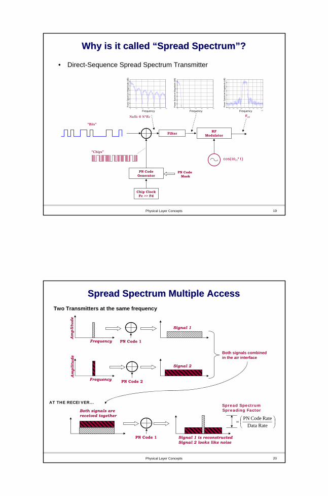
Why is it called Why is it called ““Spread SpectrumSpread Spectrum””??
• Direct-Sequence Spread Spectrum Transmitter
PN Code Generator
Chip ClockFc >> Fd
RF Modulator
cos(ωrf*t)
Nulls @ N*Rc Frf
Filter
PN Code Mask
“Bits”
“Chips”
0 0.1 0.2 0.3 0.4 0.5 0.6-50
-40
-30
-20
-10
0
10
Frequency
Pow
er S
pect
rum
Mag
nitu
de (d
B)
0 0.1 0.2 0.3 0.4 0.5 0.6-60
-50
-40
-30
-20
-10
0
10
Frequency
Pow
er S
pect
rum
Mag
nitu
de (d
B)
0.2 0.4 0.6 0.8 1 1.2 1.4 1.6 1.8
x 107
-40
-20
0
20
40
60
80
Frequency
Pow
er S
pect
rum
Mag
nitu
de (d
B)
Physical Layer Concepts 20
Spread Spectrum Multiple AccessSpread Spectrum Multiple Access
⎟⎠⎞
⎜⎝⎛=
Rate DataRate Code PN
Both signals combinedin the air interface
PN Code 1Frequency
Am
plit
ude
Signal 1
PN Code 2Frequency
Am
plit
ude
Signal 2
Spread SpectrumSpreading Factor
PN Code 1 Signal 1 is reconstructedSignal 2 looks like noise
Both signals arereceived together
AT THE RECEIVER...
Two Transmitters at the same frequency

Physical Layer Concepts 21
SSMA PN Code PlanningSSMA PN Code Planning
Uplink: PN Code used to distinguish each Mobile StationDownlink: PN Code used to distinguish each Base Station
PN3 PN4
PN1 PN1
Cell Site “1” transmits using PN code 1
PN5 PN6
PN2 PN2
Cell Site “2” transmits using PN code 2
Physical Layer Concepts 22
SSMA PN Code PlanningSSMA PN Code Planning
Spread Spectrum Code Planning ExampleN
S
W
PN1
PN2
PN3PN7
PN6 PN4
PN5
PN7
PN6 PN4
PN5
PN1
PN2
PN3
PN1
PN2
PN3PN7
PN6 PN4
PN5
PN1
PN2
PN3PN7
PN6 PN4
PN5
PN1
PN2
PN3PN7
PN6 PN4
PN5 PN1
PN2
PN3PN7
PN6 PN4
PN5
E
Physical Layer Concepts 23
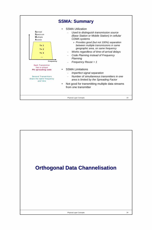
Tx 1
Tx 2
Tx 3
...
SSMA: SummarySSMA: Summary
Each Transmitterhas a unique
PN spreading code
Several Transmitters share the same frequency
and time
Frequency
SpreadSpectrumMultipleAccess
• SSMA Utilization− Used to distinguish transmission source
(Base Station or Mobile Station) in cellular CDMA systems
Provides good (but not 100%) separation between multiple transmissions in same geographic area, on same frequency
− Works regardless of time-of-arrival delays− Code Planning instead of Frequency
Planning− Frequency Reuse = 1
• SSMA Limitations− Imperfect signal separation− Number of simultaneous transmitters in one
area is limited by the Spreading Factor• Not good for transmitting multiple data streams
from one transmitter
Physical Layer Concepts 24
Orthogonal Data Orthogonal Data ChannelisationChannelisation

Physical Layer Concepts 25
Orthogonal Data ChannelizationOrthogonal Data Channelization
OC 4
OC 3
OC 2
OC 1
RFModulation
RFDemod
OC 3
Data Channel 1
Data Channel 2
Data Channel 3
Data Channel 4
Receiver
In this example, receiver correlates composite received signal using Orthogonal Code 3.
Result is a perfect reconstruction of Data Channel #3, with no interference from other data channels.
To realize this perfect cross-correlation property, it is essential that orthogonal codes be received in perfect timing relation to each other.
Linear Addition
Transmitter
PN 1 PN 1
Physical Layer Concepts 26
Orthogonal CodesOrthogonal Codes
Uplink: Orthogonal Codes used to distinguish data channelscoming from each Mobile Station
Downlink: Orthogonal Codes used to distinguish data channelsComing from each Base Station
OC1, OC2OC3, OC4
OC5, OC6, OC7
OC1 , OC2, OC3OC1, OC2
OC1, OC2, OC3, OC4

Physical Layer Concepts 27
Orthogonal CDMA: SummaryOrthogonal CDMA: Summary
• CDMA allows multiple data streams to be sent on the same RF carrier
Perfect isolation between data streamsTiming between data streams must be exactMaximum number of data channels = orthogonal code length
The longer the code, the slower the data rate
• Code space can be rapidly re-allocated to match user data rate requirements
• CDMA advantages are limited in practiceMultipath, small timing errors, and motion-related effects diminish the usable code space
Data 1
Data 2
Data 3
...
Each Data Stream has a unique
Orthogonal spreading code
Many users share the same frequency and time
IS-95, cdma2000, WCDMA
Frequency
CodeDivision Multiple Access
Physical Layer Concepts 28
Cellular CDMA (SSMA + OC)Cellular CDMA (SSMA + OC)
• Cellular CDMA (IS-95, cdma2000, WCDMA)
PN Codes are used:To distinguish between Mobile StationsTo distinguish between Base Stations
Orthogonal Codes are used:To distinguish between data channels coming from each MSTo distinguish between data channels from each BS
User 1
User 2
User 3
...
PN Spreading Codes
and
Orthogonal Codes
are simultaneously utilized
Frequency
CodeDivision Multiple Access
SpreadSpectrumMultipleAccess

Physical Layer Concepts 29
Cellular CDMA (SSMA + OC)Cellular CDMA (SSMA + OC)
2 data channels(voice, control)
PN3 + OC1 + OC2
2 data channels(14 kbps data, control)
PN4 + OC1 + OC2
2 data channels(voice, control)
PN1 + OC1 + OC2
1 data channels(control)
PN1 + OC3Voice
Conversation Uplink Packet Data
Pilot, BroadcastPN1 + OCP + OCB
3 data channels(voice, video, control)
PN2 + OC1 + OC2 + OC3
3 data channels(voice, video, control)
PN5 + OC1 + OC2 + OC34 data channels
(384 kbps data, voice, video, control)PN6 + OC1 + OC2 + OC3 + OC4
4 data channels(384 kbps data, voice, video, control)
PN2 + OC4 + OC5 + OC6 + OC7Video
conference
Videoconference with Data
Pilot, BroadcastPN2 + OCP + OCB
Physical Layer Concepts 30
Cellular CDMA Code LayeringCellular CDMA Code Layering
Function IS-95A/B cdma2000(1x, RC 3~9)
WCDMA
DataChannelization
Orthogonal64 chip
OVSF4 ~ 256 chip
OVSF4 ~ 512 Chip
BTS Separation “Short PN Code”215 chip
Same as IS-95
38,400 chipsof 2 18 Gold codeDownlink
Data Encryption
“Long PN Code”(242 –1) chip
Same as IS-95
None*
DataChannelization
None(only one data channel at a time)
OVSF4 ~ 256 chip
OVSF4 ~ 256 Chip
MSSeparation
“Long PN Code”(242 –1) chip
Same as IS-95
38,400 chipsof 225 Gold codeUplink
DataScrambling
Due to MS Separation Code
Same as IS-95
None*
*WCDMA implements encryption at higher layers

Physical Layer Concepts 31
OC-N
OC-2
OC-1
RFModulation
RFDemod
OC-2
Data Channel 1
Data Channel 2
Data Channel 3
Receiver1
Σ
Transmitter 1
Codes in WCDMA
SC-2
RFModulation
Transmitter 2
SC-M
RFModulation
Transmitter M
SC-1..
..
SC-1
Scrambling Code (SC)Used to distinguish transmission source (Base Station or Mobile Station)
Orthogonal Code (OC)allows multiple data streams to be sent on the same RF carrier
Physical Layer Concepts 32
Practical Issues with Codes• UEs near to cell edge experiences higher interference due to
− DL channels from neighbour cells (iother)− Degraded orthorgonality of own cell’s channels (iown)
• When there is little multipath with a cell, there is little mutual interference between DL channels
• Antenna downtilt is used to manage interference from other cells
UE3
PN 1
PN 2
OC 1OC 2
UE2
UE1
CPICH+CCH

Physical Layer Concepts 33
SummarySummary1. Multiple Access Approaches
− FDMA, TDMA, CDMA (SSMA)− Channel Capacity
2. Code Correlation− Correlation and Orthogonality− DS Spread Spectrum System− Code Correlation using PN Codes and Orthogonal Codes
3. Spread Spectrum Multiple Access (SSMA) Using PN Codes4. Orthogonal Data Channelisation