Embed Size (px)
Citation preview

Application of geo-engineering knowledge in designing
Shallow Foundations -3
ENB371: Geotechnical Engineering 2
Combined & Matt (Raft) FoundationsField tests used in shallow foundation design
Chaminda

Chapter Chapter 5 5 & & 66
BRAJA M. DASBRAJA M. DAS

Content……
• Combined Footings (supports a line of two or more columns)
• Mat or Raft Foundations (supports more than one line of columns)
Field tests in Foundation system• Plate load test• Standard Penetration Test (SPT)• Cone Penetration Test (CPT)

Combined Footings
Under normal conditions, spread footings (square,rectangular, circular) and strip footings are economical t osupport columns and walls.
However, under certain circumstances (restrained byproperty line) it is desirable to construct a footing that
• Rectangular Combined Footing• Trapezoidal Combined Footing• Cantilever Footing
property line) it is desirable to construct a footing thatsupport a line of two or more columns

Combined Footings (cont..)Rectangular combined footing
Location of the resultant of the column loads, X
21
32
LQX
+=
For a uniform distribution of soil pressure: theresultant load should pass through the centreof the foundation . Thus,of the foundation . Thus,
foundation theoflength where
)(2 2
=+=
L
XLL
Once the L is determined, L2
321 LLLL −−=Assume B and calculate net allowable bearing pressure, q net(all) , using Meyerhof BearingCapacity Theory and FS .
FS
qq unet
allnet)(
)( = 21)( )( QQLBq allnet +≥××

Combined Footings (cont..)Trapezoidal combined footing
Assume B 1 and B 2 , then the effective width B:
21
32
LQX
+=
From the property of a trapezoid
Location of the resultant of the column loads, X2
21 BBB
+=
3
2
21
212
L
BB
BBLX
++=+
LBB
A2
21 +=Calculate net allowable bearing pressure, q net(all) , using Meyerhof Bearing CapacityTheory, FS , B, and L
FS
qq unet
allnet)(
)( =21)( QQAq allnet +≥×
Once the L is determined, area of the foundation, A

Combined Footings (cont..)Cantilever Footing
• Cantilever footing uses a strap beam to connecteccentrically loaded column foundation to the foundationof an interior column.
• Cantilever footings may be used in place of rectangular ortrapezoidal combined footings when the allowable bearingcapacity is high and distances between columns are large
Mat (Raft) Foundations
• Supports more than one line of columns
• Use with soil that has low bearing capacity
• If spread footings covering more than the• If spread footings covering more than thehalf of building area, Mat foundation mightbe more economical

Mat (Raft) Foundations (cont..)Types of Mat Foundations
(a) Flat Plate (b) Flat Plate thickened under column

Mat (Raft) Foundations (cont..)Types of Mat Foundations
(c) Beams and Slab (d) Slab with Basement Walls

Mat (Raft) Foundations (cont..)Bearing Capacity of Mat Foundation
Comparison of isolated foundation and mat foundatio n ( B = width, D f = depth)
Same procedure as square or rectangular spread footing
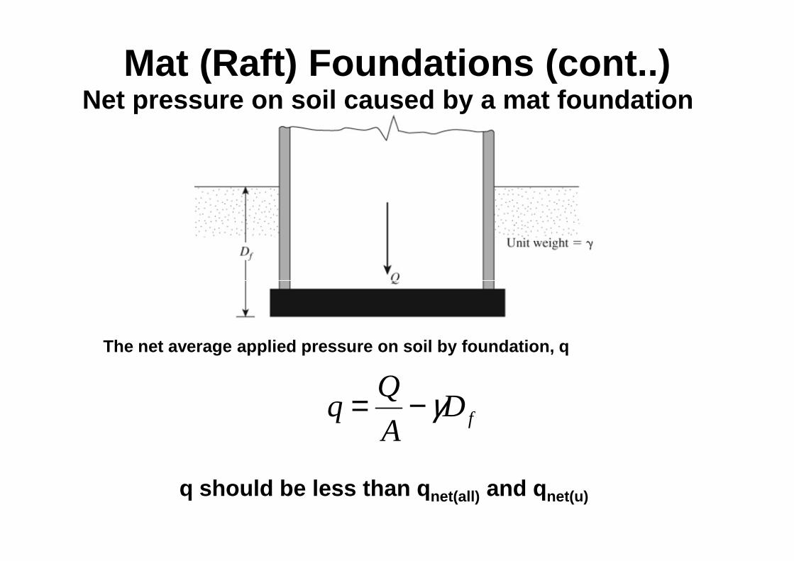
Mat (Raft) Foundations (cont..)Net pressure on soil caused by a mat foundation
The net average applied pressure on soil by foundation, q
fDA
Qq γ−=
q should be less than q net(all) and q net(u)

Mat (Raft) Foundations (cont..)Net pressure on soil caused by a mat foundation
This indicates that the net pressure increase in soil under t he foundation canbe reduced by increasing the depth (D f) of mat foundation
fDA
Qq γ−=
This relation for Df is referred to as the depth of a fully compensated foundation
For no increase in the net pressure on the soil below the mat fo undation, qshould be zero. Thus,
γγ
A
QDD
A
Qff =⇒−=0

Example -1A mat foundation on a saturated clay soil has dimen sions of 20 m x 20 m. Given: dead and live load = 48 MN, c u = 30 kN/m2, and γγγγclay = 18.5 kN/m3.
(a) Find the depth , D f, of the mat to be fully compensated foundation.(b) What will be the depth of the mat (D f) for a factor of safety of 2
against bearing capacity failure?

Example -1(Solution)
2
3
/30
/5.18
48
20
20
mkNc
mkN
MNQ
mL
mB
u
clay
=
====
γ
The net average applied pressure on soil by foundation, q
QfD
A
Qq γ−=
To be fully compensated foundation, q = 0. Thus,
mA
QD f 49.6
5.18)2020(
100048 =××
×==γ

Example -1(Solution)
2
3
/30
/5.18
48
20
20
mkNc
mkN
MNQ
mL
mB
u
clay
=
====
γ
Meyerhof bearing capacity equation
idsqiqdqsqcicdcscu FFFBNFFFqNFFFNcq γγγγγ5.0' ++=For undrained condition, φφφφ=0, thus N c=5.14, Nq=1, Nγγγγ=0
Shape factors,
19.114.5
1
20
2011 =
+=
+=c
qcs N
N
L
BF
10tan20
201'tan1 =
+=
+= φL
BFqs

Example -1(Solution)
No load inclination 1=== FFF
Depth factors, assume 1≤B
D f
+=
+=
204.014.01 ff
cd
D
B
DF
120
)0sin1(0tan21)sin1('tan21 22 =
−+=
−+= ff
qd
D
B
DF φφ
idsqiqdqsqcicdcscu FFFBNFFFqNFFFNcq γγγγγ5.0' ++=No load inclination 1=== iqici FFF γ
idsqiqdqsqcicdcscu FFFBNFFFqNFFFNcq γγγγγ5.0' ++=
ff
fu
DD
qD
q
γ+
+×=
××××+
+×××=
204.015.183
1111)20
4.01(19.114.530

Example -1(Solution)
+×=−+
+×=
204.015.183
204.015.183)(
fff
funet
DDD
Dq γγ
fuunet Dqq γ−=)(
fffappnet DDDA
Qq 5.181205.18
2020
48000)( −=−
×=−= γ
A 2020×
)(
)(
appnet
unet
q
qFS =
mDD
D
ff
f
4.15.18120
204.015.183
2 =⇒−
+×
=
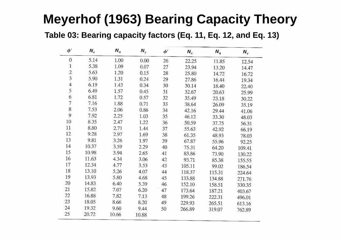
Meyerhof (1963) Bearing Capacity Theory Table 03: Bearing capacity factors (Eq. 11, Eq. 12, and Eq. 13)

Field tests in Foundation system• Plate load test• Standard Penetration Test (SPT)• Standard Penetration Test (SPT)• Cone Penetration Test (CPT)
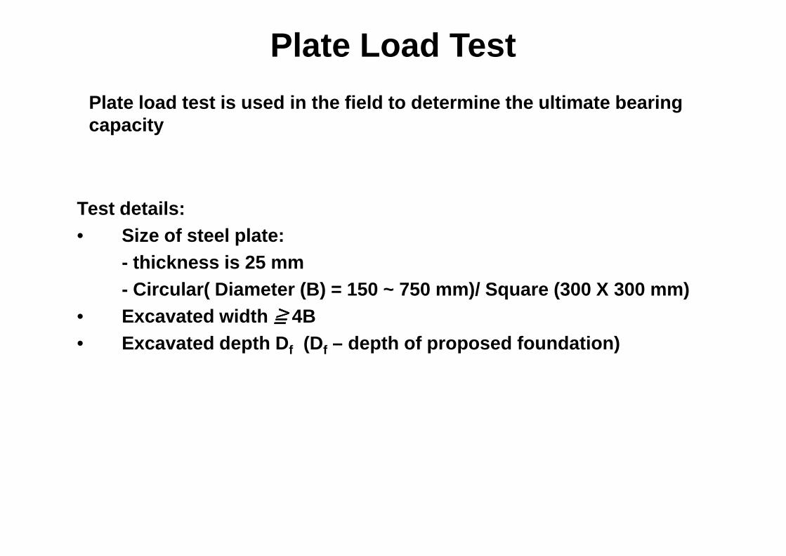
Plate Load Test
Plate load test is used in the field to determine t he ultimate bearing capacity
Test details:• Size of steel plate:
- thickness is 25 mm
≧≧≧≧
- Circular( Diameter (B) = 150 ~ 750 mm)/ Square (30 0 X 300 mm)• Excavated width ≧≧≧≧ 4B• Excavated depth D f (Df – depth of proposed foundation)
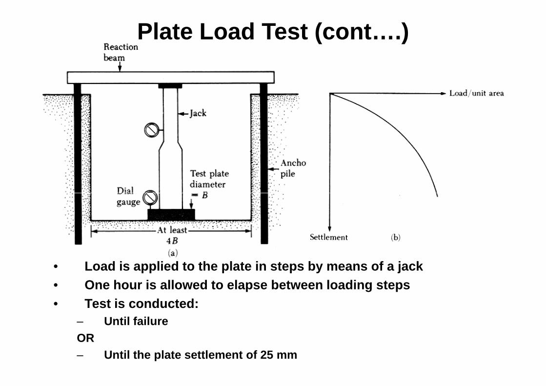
Plate Load Test (cont….)
• Load is applied to the plate in steps by means of a jack• One hour is allowed to elapse between loading steps• Test is conducted:
– Until failureOR– Until the plate settlement of 25 mm

Plate Load Test (cont….)

Plate Load Test (cont…)
qu(P) is obtained from plate loading test (stress at the failure of the test plate OR stress at 25 mm settlement of bearing plat e
For test in clay:
plate test theofcapacity mearing Ultimate
foundation proposed theofcapacity bearing Ultimate
)(
)(
=
=
Pu
Fu
q
q
qu(F) , SFq S
Plate Footing
For test in clay:
)()( PuFu qq =
For test in sandy soils:
P
FPuFu B
Bqq )()( =
plate test theofwidth
foundation theofwidth
==
P
F
B
B
BP BF
qu(F) , SFqu(P), SP
~2.5BF
~2.5BP
~ 0.1q
q

Plate Load Test (cont…)
For clayey soil:
FPF B
BSS =
plate test theof settlement
foundation theof settlement
==
P
F
S
S
Plate Footing
The allowable bearing capacity of a foundation, bas ed on the settlement consideration and for the given intensit y of load, q 0 , is
)foundation theof stress bearing is ( If 00)()( qqqq PF ==
PPF B
SS =
For sandy soils:
22
+=
PF
FPF BB
BSS
BP BF
qu(F) , SFqu(P), SP
Plate Footing
~2.5BF
~2.5BP
~ 0.1q
q
mmSF 25≤
)foundation theof stress bearing is ( If 00)()( qqqq PF ==

Example -1The results of a plate loading test on a sandy soil are shown in the following figure. The size of the plate is 300 x 30 0 mm. Determine the size of a square column foundation that should carr y a load of 2500 kN with the maximum settlement of 25 mm.

Example -1 (solution)This problem has to be solved by trial and error
Q0 [kN] Assume widthBF [m]
[kPa] SP [mm]From given chart
SF [mm]Settlement of foundation
2500 4.0 156.25 4.0 13.85
2500 3.0 277.80 8.0 26.45
2500 3.2 244.10 6.8 22.74
FA
Qq 0
0 =
2500 3.2 244.10 6.8 22.74
2500 3.1
22
+=
PF
FPF BB
BSS
BF = width of foundationBP = width of plate = 300 mm

Standard Penetration Test (SPT)
• 63.5 kg mass is dropped through 760 mm to make one blow on the SPT spoon.
• Number of blows to penetrate three 150 mm distances are measured given as x/y/z
• The blows for first 150 mm are discarded.• The number of blows for next 300 mm is
taken as the “raw” blow count or standard taken as the “raw” blow count or standard penetration number, i.e., N=y+z
• N is measured at every 0.75 m or 1.5 m depth
The “raw” blow count or standard number (N) should be corrected for:
(1) Water table(2) Effective overburden pressure
Refusal100mm) 450 allfor ( N if
50 mm 300(for N if OR
>>

Standard Penetration Test (SPT) – Cont…
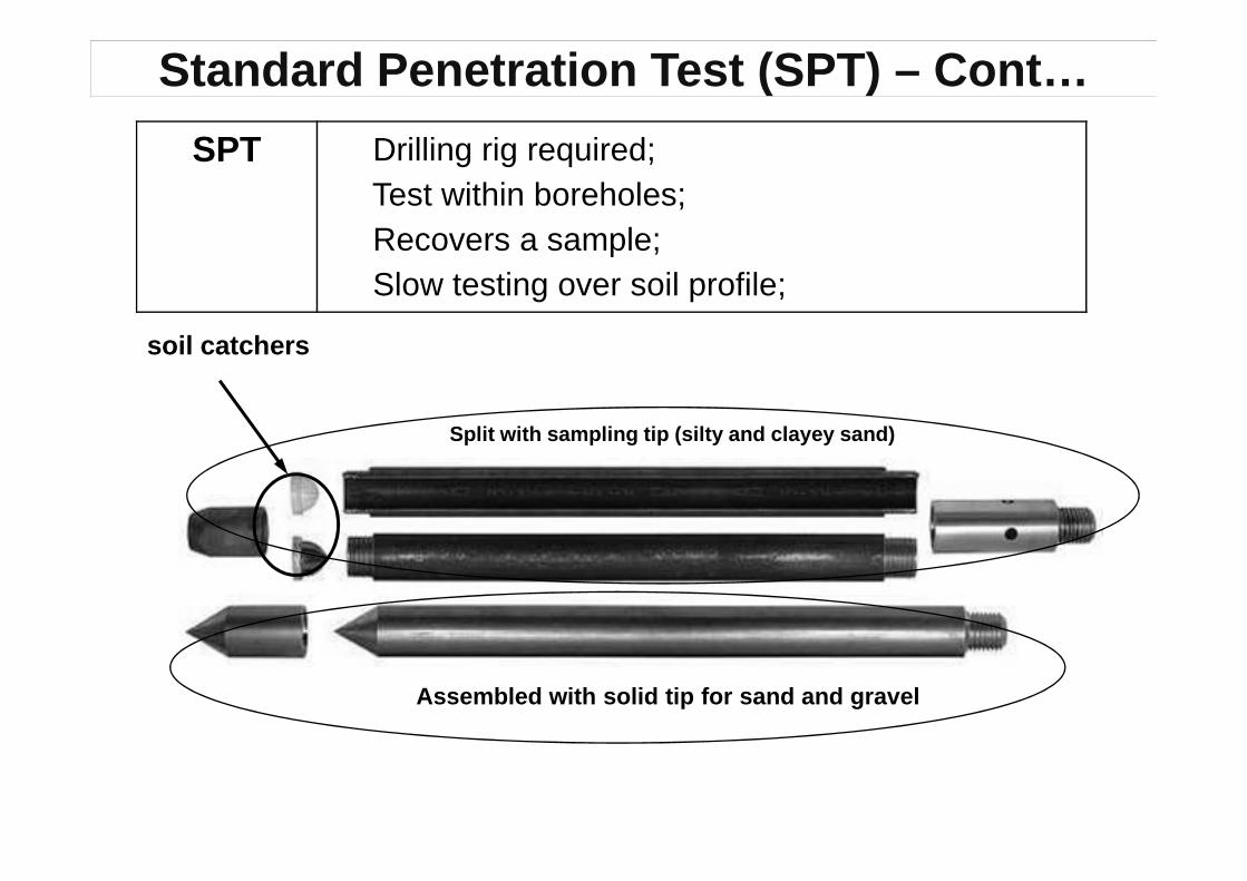
SPT Drilling rig required; Test within boreholes; Recovers a sample; Slow testing over soil profile;
Split with sampling tip (silty and clayey sand)
soil catchers
Standard Penetration Test (SPT) – Cont…
Split with sampling tip (silty and clayey sand)
Assembled with solid tip for sand and gravel

Standard Penetration Test (SPT) – Cont…Corrections to “raw” N
Correction 1 - Water table correction:When SPT test is carried out in fine sand or silty sand below the water
table, the measured N, if greater than 15, should b e corrected for increased resistance due to negative excess pore wa ter pressure during driving and unable to dissipate immediately
Conditions:Conditions:
1. Be below the water table
2. N> 15
3. Indication of reduced permeability (i.e., fine or silty/clayey sand)
Ncorr=15+0.5(N-15)
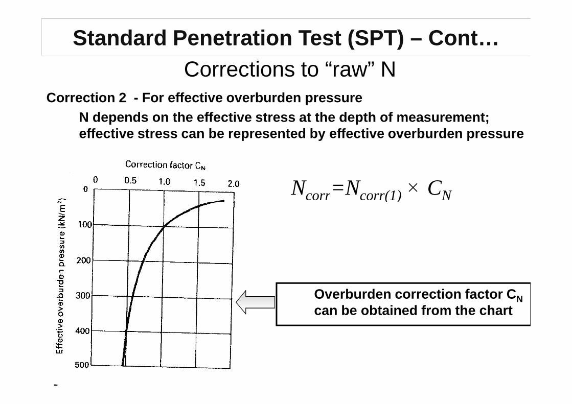
Standard Penetration Test (SPT) – Cont…Corrections to “raw” N
Correction 2 - For effective overburden pressureN depends on the effective stress at the depth of m easurement; effective stress can be represented by effective ov erburden pressure
Ncorr=Ncorr(1) × CN
Overburden correction factor C Ncan be obtained from the chart
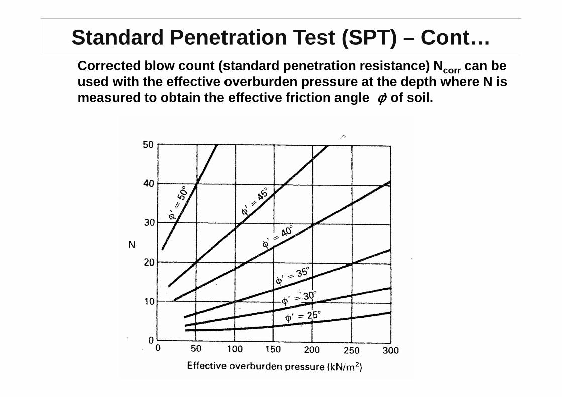
Standard Penetration Test (SPT) – Cont…Corrected blow count (standard penetration resistan ce) Ncorr can be used with the effective overburden pressure at the depth where N is measured to obtain the effective friction angle φφφφ’ of soil.
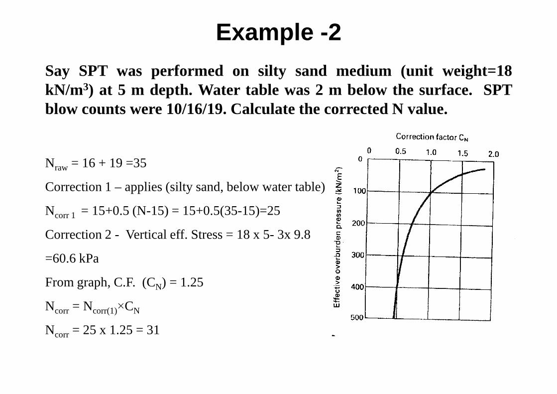
Example -2
Say SPT was performed on silty sand medium (unit weight=18kN/m3) at 5 m depth. Water table was 2 m below the surface. SPTblow counts were 10/16/19. Calculate the corrected N value.
Nraw = 16 + 19 =35
Correction 1 – applies (silty sand, below water table)
Ncorr 1 = 15+0.5 (N-15) = 15+0.5(35-15)=25
Correction 2 - Vertical eff. Stress = 18 x 5- 3x 9.8
=60.6 kPa
From graph, C.F. (CN) = 1.25
Ncorr = Ncorr(1)×CN
Ncorr = 25 x 1.25 = 31
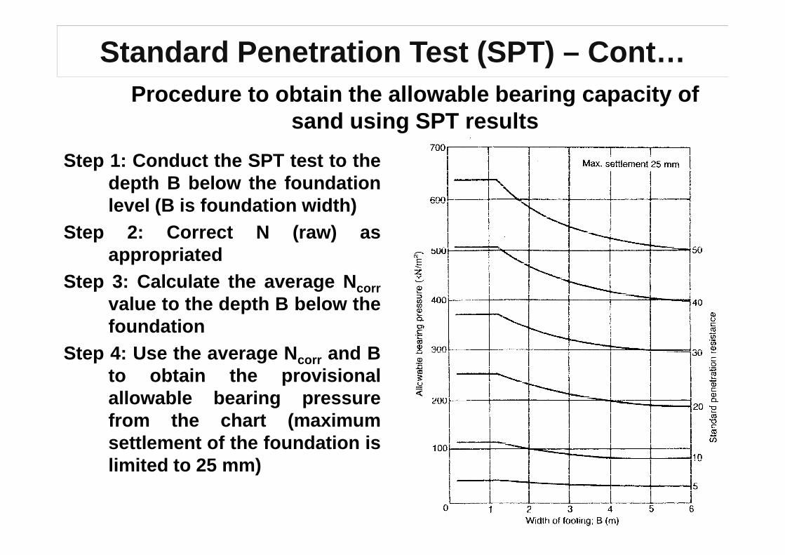
Standard Penetration Test (SPT) – Cont…Procedure to obtain the allowable bearing capacity of
sand using SPT results
Step 1: Conduct the SPT test to thedepth B below the foundationlevel (B is foundation width)
Step 2: Correct N (raw) asappropriated
Step 3: Calculate the average NStep 3: Calculate the average Ncorrvalue to the depth B below thefoundation
Step 4: Use the average N corr and Bto obtain the provisionalallowable bearing pressurefrom the chart (maximumsettlement of the foundation islimited to 25 mm)

Standard Penetration Test (SPT) – Cont…Procedure to obtain the allowable bearing capacity of
sand using SPT results
Step 5: To correct the provisional value of allowable bearin g pressure, itshould be multiplied by a factor C w ,
D
If )(0 BDD fw +≤≤
D fDwD
If )( BDD fw +>
BD
DC
f
ww +
+= 5.05.0
0.1=wC
Thenwprovallall Cqq ×= )(

Example -3
A footing 3 x 3 m is to be located at a depth of 1.5 m in a sanddeposit, the water table being 3.5 m below the surface. The values ofstandard penetration resistance were determined as given below.Determine the allowable bearing capacity of the foundation. Theunit weights of sand above and below water table are 17 kN/m2 and19.8 kN/m2, respectively.Depth (m) N
0.75 80.75 8
1.55 7
2.30 9
3.00 13
3.70 12
4.45 16
5.20 20

Example -3
Water table correction is not necessary - sandDepth (m) N σ’v [kN/m2] CN Ncorr=N*CN
0.75 8 13
1.55 7 26 2.0 14
2.30 9 39 1.6 14
3.00 13 51 1.4 18
3.70 12 62 1.25 153.70 12 62 1.25 15
4.45 16 69 1.2 19
5.20 20 77
(av) = 16
B = 3 m, and the corrected average N = 16, therefore
The provisional allowable bearing capacity = 165 kN/m2 (from chart)
89.0)5.13(
5.35.05.05.05.0 =
+×+=
++=
f
ww DB
DC
qall = Cw×qall(prov)=0.89×165 =150 kN/m2

Cone Penetration Test (CPT)
A cone having an apex angle 600 and the diameter of 35.7 mm2
(projected area of cone is 1000 mm2) is pushed directly into the ground at a rate of 20 mm/sec by means of static thrust.

Cone Penetration Test (CPT) (cont..)

Cone Penetration Test (CPT) (cont…)

– No drilling
– No soil sample
– Much information
– penetration resistance, qc & sleeve friction, fs,
Cone Penetration Test (CPT) (cont…)
– penetration resistance, qc & sleeve friction, fs,
Pore water pressure, ..
– FR = fs/qc used to distinguish soil types
– Direct application to piling
– E = fn (qc)

Cone Penetration Test (CPT) (cont…)Typical test results
resistance tip=cq pressurewater -Pore=uFriction Sleeve=sf 100(%) ×=c
s
q
fFR
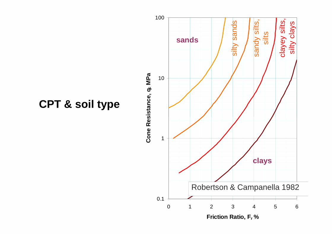
CPT & soil type
10
100
Con
e R
esis
tanc
e, q
c M
Pa
sands
silty
san
ds
sand
y si
lts,
silts
clay
ey s
ilts,
si
lty c
lays
0.1
1
0 1 2 3 4 5 6
Friction Ratio, F r %
Con
e R
esis
tanc
e, q
clays
Robertson & Campanella 1982

CPT and soil properties
Undrained shear strength
of clays,
• Nk = 12 to 15voc
u N
σqc
−=• Nk = 12 to 15
• Correlation improved if
OCR taken into account
• Direct application to piling
ku N
pressure overburden Total
resistance Tip
strengthshear Undrained
vo ===
σu
u
q
c

CPT and soil properties
Shear strength of clean sands
′+=′
vo
cq
σφ log38.01.0arctanmax
Shear strength parameters
obtained from CPT can be
used for bearing capacity
calculation of shallow
foundation

Settlement of shallow foundation -1
Width of the foundation (B) is decided
from ultimate bearing capacity analysis
to satisfy the given FS ( Q all is
foundation load from super-structure)
allQ
B
Sand
x
Clay
Calculate the total settlement of the foundation (elastic & consolidation)
considering soil properties and foundation stress distrib ution to the
depth of 1.5 B (square, rectangular, circular footing) OR 3B for strip
foundations
Ultimate Limit State

Settlement of shallow foundation -2
(Stresses in soil & elastic deformation of soil) – lecture 2 a nd 3
ionconsolidatelasticTotal SSS +=foundation under the SandClay / of settlement )(immediate Elastic=elasticS
foundation under theclay of settlemention Consolidat=ionconsolidatS
(Stresses in soil & consolidation) – lecture 4 and 5(Stresses in soil & consolidation) – lecture 4 and 5
IF)max(allowableTotal SS ≤
)foundation shallow isolatedfor mm 45 ~ 25 ( standarddesign in given is )max(allowableS
Satisfied Serviceability Limit State
IF NOT, increase the foundation size, calculate S Total and checkserviceability limit state
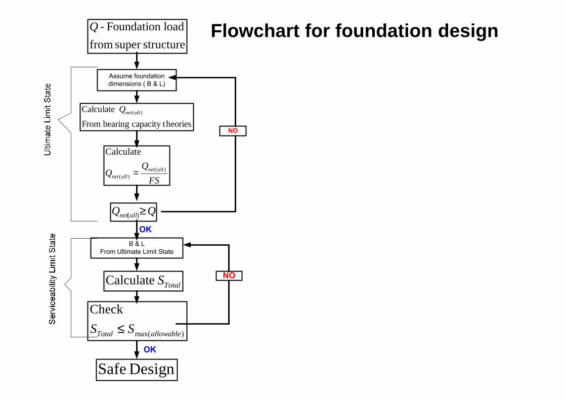
Flowchart for foundation design
Assume foundation
dimensions ( B & L)
FS
QQ ultnet
allnet)(
)(
Calculate
=
structuresuper from
load Foundation - Q
heoriescapacity t bearing From
Calculate )(ultnetQ
NO
QQ allnet ≥)(
B & L
From Ultimate Limit State
TotalS Calculate
Design Safe
)max(
Check
allowableTotal SS ≤
NO
OK
OK