Embed Size (px)
Citation preview

8/11/2019 01 Week 10 - Lecture Notes - A Slide Per Page -Gray
http://slidepdf.com/reader/full/01-week-10-lecture-notes-a-slide-per-page-gray 1/57
CHAPTER 11:CHAPTER 11:
PILE FOUNDATIONSPILE FOUNDATIONS
PART A
BRAJA M. DAS BRAJA M. DAS

8/11/2019 01 Week 10 - Lecture Notes - A Slide Per Page -Gray
http://slidepdf.com/reader/full/01-week-10-lecture-notes-a-slide-per-page-gray 2/57
Contents…..
Introduce deep foundation
PP
Introduce various types of piles
Pile driving
How to estimate pile capacity?
End resistance in soil and rock, h a f t
Shaft resistance in soil
End End

8/11/2019 01 Week 10 - Lecture Notes - A Slide Per Page -Gray
http://slidepdf.com/reader/full/01-week-10-lecture-notes-a-slide-per-page-gray 3/57
Applications
Large Distributed Large Distributed Weight Weight
Very Large Concentrated Very Large Concentrated Weight Weight
ow ow Weight Weight
Soft to Soft to Firm Clay Firm Clay
Dense Sand
Stron Rock Stron Rock

8/11/2019 01 Week 10 - Lecture Notes - A Slide Per Page -Gray
http://slidepdf.com/reader/full/01-week-10-lecture-notes-a-slide-per-page-gray 4/57
Why do we require a pile?
a. Transfer load to a stronger strata: Top layers of soil are highly
compressible and too weak to support the load transmitted by thesuperstructure.
b. Transfer the structural load to the soil throu h frictional
resistance developed at soil-pile interface: The bedrock isnot encountered at reasonable depth below the ground surface
c. Carry horizontal loads: Lateral forces are relatively prominent
d. In presence of expansive and collapsible soils at the site
e. Foundations subjected to uplift forces: transmissiontowers, offshore platforms, basement mats below thewater table
f. To avoid the loss of bearing capacity due to erosion andscouring

8/11/2019 01 Week 10 - Lecture Notes - A Slide Per Page -Gray
http://slidepdf.com/reader/full/01-week-10-lecture-notes-a-slide-per-page-gray 5/57

8/11/2019 01 Week 10 - Lecture Notes - A Slide Per Page -Gray
http://slidepdf.com/reader/full/01-week-10-lecture-notes-a-slide-per-page-gray 6/57
Why do we require a pile?

8/11/2019 01 Week 10 - Lecture Notes - A Slide Per Page -Gray
http://slidepdf.com/reader/full/01-week-10-lecture-notes-a-slide-per-page-gray 7/57

8/11/2019 01 Week 10 - Lecture Notes - A Slide Per Page -Gray
http://slidepdf.com/reader/full/01-week-10-lecture-notes-a-slide-per-page-gray 8/57
Types of piles based on Materials -2► Concrete Piles:
Cast-in-situ piles Pre-cast piles
Advantages:
Usual length: 10 m – 45 mUsual Load: 7500 kN – 8500 kN
Usual length: 5 m – 15 mUsual Load: 300 kN – 3000 kN
• Relatively cheap.• It can be easily combined with concrete superstructure• Corrosion resistant• It can bear hard driving
Disadvantages:
• Difficult to transport• Difficult to achieve desired cutoff

8/11/2019 01 Week 10 - Lecture Notes - A Slide Per Page -Gray
http://slidepdf.com/reader/full/01-week-10-lecture-notes-a-slide-per-page-gray 9/57
Types of piles based on Materials -3► Timber Piles:
Advantages:• Low const and renewable resource• Easy to handle• Can be joined together easily
Usual length: 6 m – 25 mUsual Load: 150 kN – 600 kN
•
Disadvantages:• Limited bearing capacity• Can easily be damaged during driving• The piles will rot above the water table
► Composite Piles:
combination of different materials in the same pile

8/11/2019 01 Week 10 - Lecture Notes - A Slide Per Page -Gray
http://slidepdf.com/reader/full/01-week-10-lecture-notes-a-slide-per-page-gray 10/57
Types of piles based on their function
► End bearing piles: Transfer their load to a firm stratum at the toe of the pile
► Friction piles: Transfer their load to the ground through skin friction
► Combination of friction and end bearing piles

8/11/2019 01 Week 10 - Lecture Notes - A Slide Per Page -Gray
http://slidepdf.com/reader/full/01-week-10-lecture-notes-a-slide-per-page-gray 11/57
Types of piles based on their installation
► Displacement piles: Driven concrete, Timber, or Steel piles
► Non-displacement piles: Bored Cast-in-situ piles
Displacement pile Non-displacement pile
Di l t ilDi l t il

8/11/2019 01 Week 10 - Lecture Notes - A Slide Per Page -Gray
http://slidepdf.com/reader/full/01-week-10-lecture-notes-a-slide-per-page-gray 12/57
Displacement pilesDisplacement piles In loose cohesionless soils
Densifies the soil upto a distance of 3.5 times the pile diameter (3.5D) whichincreases the soil’s resistance to shearing
The friction angle varies from the pile surface to the limit of compacted soil
In dense cohesionless soils
The dilatancy effect decreases the friction angle within the zone of influence of displacement pile ( 3.5D approx.).
Displacement piles are not effective in dense sands due to above reason.
In cohesive soils
Soil is remolded near the displacement piles (2.0 D approx.) leading to a.
Pore-pressure is generated during installation causing lower effective stress andconsequently lower shearing resistance.
Excess pore-pressure dissipates over the time and soil regains its strength.
Example: Driven concrete piles, Timber or Steel piles
NN di l t ildi l t il

8/11/2019 01 Week 10 - Lecture Notes - A Slide Per Page -Gray
http://slidepdf.com/reader/full/01-week-10-lecture-notes-a-slide-per-page-gray 13/57
NonNon--displacement pilesdisplacement piles
Due to no displacement during installation, there is no heave in theground.
Cast in-situ piles may be cased or uncased (by removing casing as .
if economical with their reduced diameter.
Enlarged bottom ends (three times pile diameter) may be providedin cohesive soils leading to much larger point bearing capacity.
Soil on the sides may soften due to contact with wet concrete orduring boring itself. This may lead to loss of its shear strength.
Concreting under water may be challenging and may resulting inwaisting or necking of concrete in squeezing ground.
Example: Bored cast in-situ or pre-cast piles

8/11/2019 01 Week 10 - Lecture Notes - A Slide Per Page -Gray
http://slidepdf.com/reader/full/01-week-10-lecture-notes-a-slide-per-page-gray 14/57
Pile Driving, Then and NowPile Driving, Then and Now

8/11/2019 01 Week 10 - Lecture Notes - A Slide Per Page -Gray
http://slidepdf.com/reader/full/01-week-10-lecture-notes-a-slide-per-page-gray 15/57
Pile HammersPile Hammers

8/11/2019 01 Week 10 - Lecture Notes - A Slide Per Page -Gray
http://slidepdf.com/reader/full/01-week-10-lecture-notes-a-slide-per-page-gray 16/57
Pile HammersPile Hammers

8/11/2019 01 Week 10 - Lecture Notes - A Slide Per Page -Gray
http://slidepdf.com/reader/full/01-week-10-lecture-notes-a-slide-per-page-gray 17/57
TerminologyTerminology

8/11/2019 01 Week 10 - Lecture Notes - A Slide Per Page -Gray
http://slidepdf.com/reader/full/01-week-10-lecture-notes-a-slide-per-page-gray 18/57

8/11/2019 01 Week 10 - Lecture Notes - A Slide Per Page -Gray
http://slidepdf.com/reader/full/01-week-10-lecture-notes-a-slide-per-page-gray 19/57

8/11/2019 01 Week 10 - Lecture Notes - A Slide Per Page -Gray
http://slidepdf.com/reader/full/01-week-10-lecture-notes-a-slide-per-page-gray 20/57
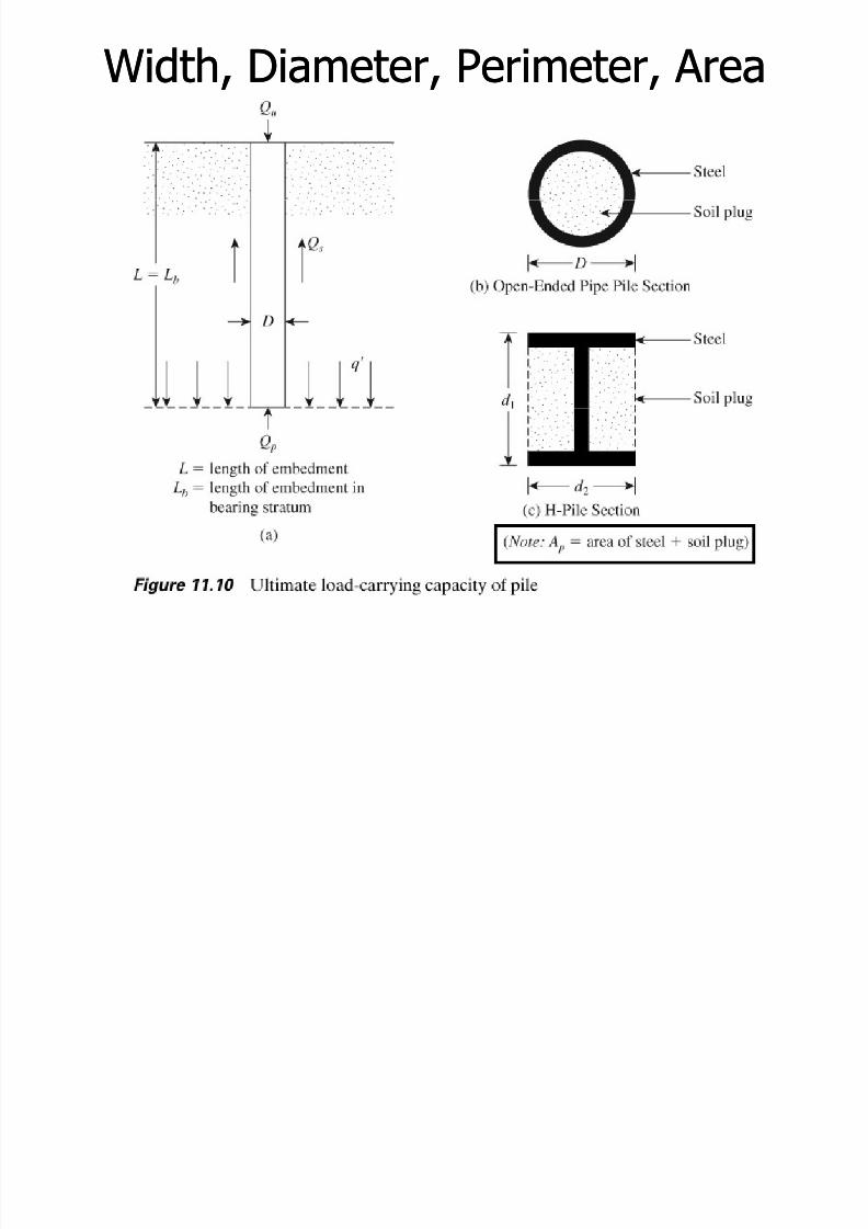
Point Bearing Capacity, QPoint Bearing Capacity, Qpp►► For shallow foundation:For shallow foundation:
qquu = c’ N= c’ Ncc + q N+ q Nqq + 0.5+ 0.5 γ γ B NB Nγ γ -- stripstripqquu = 1.3 c’ N= 1.3 c’ Ncc + q N+ q Nqq + 0.4+ 0.4 γ γ B NB Nγ γ -- squaresquare
= 1.3 c’ N= 1.3 c’ N + N+ N + 0.3+ 0.3 B NB N -- circularcircular
►► Similarly, for pile tip:Similarly, for pile tip:qquu = c’ N= c’ Ncc* + q N* + q Nqq* +* + γ γ D ND Nγ γ **
►►
Since D of pile is small:Since D of pile is small:
qqpp = c’ N= c’ Ncc* + q N* + q Nqq** -- this isthis is pressurepressureQQpp = A = A pp qqpp = A = A pp (c’ N(c’ Ncc* + q’ N* + q’ Nqq*)*) – – this isthis is loadload
Note that q’ is effective vertical stress at the level of pile tipNote that q’ is effective vertical stress at the level of pile tipNNcc* and N* and Nqq* are the bearing capacity factors for piles* are the bearing capacity factors for piles
A A pp = area of pile tip (may include a soil plug)= area of pile tip (may include a soil plug)
FULL MOBILISATION OF QFULL MOBILISATION OF Qpp REQUIRES VERTICAL DISPLACEMENT OFREQUIRES VERTICAL DISPLACEMENT OF1010--25% x D25% x D

8/11/2019 01 Week 10 - Lecture Notes - A Slide Per Page -Gray
http://slidepdf.com/reader/full/01-week-10-lecture-notes-a-slide-per-page-gray 21/57
Frictional Resistance, QFrictional Resistance, Qss
►►QQss == ΣΣ (p(p ∆∆L f)L f)
p = per me er o p ep = per me er o p e(may include soil plug)(may include soil plug)
∆∆L = incremental pile lengthL = incremental pile length
f = unit friction resistancef = unit friction resistance
n h kP MPn h kP MP
8/11/2019 01 Week 10 - Lecture Notes - A Slide Per Page -Gray
http://slidepdf.com/reader/full/01-week-10-lecture-notes-a-slide-per-page-gray 22/57
Width, Diameter, Perimeter, AreaWidth, Diameter, Perimeter, Area

8/11/2019 01 Week 10 - Lecture Notes - A Slide Per Page -Gray
http://slidepdf.com/reader/full/01-week-10-lecture-notes-a-slide-per-page-gray 23/57
Point Resistance, QPoint Resistance, QPP
Meyerhof’s Method for QMeyerhof’s Method for Qpp
Vesic’s Vesic’s Method for QMethod for Qpp
Coyle & Costello’s Method for QCoyle & Costello’s Method for Qpp
QQpp of piles resting on rock of piles resting on rock
Meyerhof’s Method for QMeyerhof’s Method for Q

8/11/2019 01 Week 10 - Lecture Notes - A Slide Per Page -Gray
http://slidepdf.com/reader/full/01-week-10-lecture-notes-a-slide-per-page-gray 24/57
Meyerhof s Method for QMeyerhof s Method for QppFOR GRANULAR SOIL:FOR GRANULAR SOIL:
►► c’ = 0c’ = 0►► QQpp = A = A pp qqpp = A = A pp q’ Nq’ Nqq**
►►
Limit:Limit: pp ≤≤ A A pp qqll►► qql = 0.5 p= 0.5 paa NNqq* tan* tan φφ’ ’
qqll = 0.4 p= 0.4 paa NN6060 L/DL/D
≤≤ 4 p4 paa NN6060
ppaa = 100 kPa (air pressure)= 100 kPa (air pressure)
WHEREFROM ???
φφφφφφφφ’ ’ ==Friction angleFriction angle, A , A pp == Pile tip areaPile tip area,, NNqq* =* = Bearing capacity factorBearing capacity factor
qqpp = Ultimate tip resistance,= Ultimate tip resistance, q’ q’ = Effective vertical stress at the pile tip= Effective vertical stress at the pile tip
DD = Width or diameter of the pile= Width or diameter of the pile
NN6060 = average SPT (between 10D above and 4D below the= average SPT (between 10D above and 4D below thepile point)pile point)

8/11/2019 01 Week 10 - Lecture Notes - A Slide Per Page -Gray
http://slidepdf.com/reader/full/01-week-10-lecture-notes-a-slide-per-page-gray 25/57
Depth for SPT CalculationDepth for SPT Calculation

8/11/2019 01 Week 10 - Lecture Notes - A Slide Per Page -Gray
http://slidepdf.com/reader/full/01-week-10-lecture-notes-a-slide-per-page-gray 26/57
44 NN = 4 . 100 . 30= 4 . 100 . 30 ≈≈ 1200012000
ql
= 0.4 pa
N60
L D ≤ 4 pa
N60

8/11/2019 01 Week 10 - Lecture Notes - A Slide Per Page -Gray
http://slidepdf.com/reader/full/01-week-10-lecture-notes-a-slide-per-page-gray 27/57
The mobilization of shear strength also depends on theextent of the pile’s penetration into the bearing layer. Ingranular soils, the depth ratio at which the maximumstrength is mobilized is called the critical depth ratio(Lb /D)cr , of about 15.
L = Lb for homogeneous soils (L = Embedment length of thepile)

8/11/2019 01 Week 10 - Lecture Notes - A Slide Per Page -Gray
http://slidepdf.com/reader/full/01-week-10-lecture-notes-a-slide-per-page-gray 28/57
Critical Depth: A Fallacy?Critical Depth: A Fallacy?
►► Many texts suggest the existence of a critical depth, belowMany texts suggest the existence of a critical depth, belowwhich the shaft and toe resistances would be constant.which the shaft and toe resistances would be constant.
►► Fellenius & Altaee (1995) showed that the aboveFellenius & Altaee (1995) showed that the aboveassumption is wrong and may be based on incorrectassumption is wrong and may be based on incorrectinterpretation of field data.interpretation of field data.
►►
However, along very long offshore piles, the phenomenonHowever, along very long offshore piles, the phenomenonmay occur.may occur.
,,exists. But please be aware that you mayexists. But please be aware that you mayhave to discard this assumption in thehave to discard this assumption in the
real world!real world!
Meyerhof’s Method for QMeyerhof’s Method for Qpp

8/11/2019 01 Week 10 - Lecture Notes - A Slide Per Page -Gray
http://slidepdf.com/reader/full/01-week-10-lecture-notes-a-slide-per-page-gray 29/57
Meyerhof s Method for QMeyerhof s Method for QppFOR clay SOILFOR clay SOIL (φ(φ’ =0)’ =0)::
►► QQpp = A = A pp ccuu NNcc*=9c*=9cuu A A pp
A A pp == Pile tip areaPile tip area,, NNcc* =* = Bearing capacity factorBearing capacity factor
CCuu = undrained cohesion of the soil below the tip of the pile= undrained cohesion of the soil below the tip of the pile

8/11/2019 01 Week 10 - Lecture Notes - A Slide Per Page -Gray
http://slidepdf.com/reader/full/01-week-10-lecture-notes-a-slide-per-page-gray 30/57
ExampleExample --11
►► A concrete pile is 14 m long and 400 mm x A concrete pile is 14 m long and 400 mm x400 mm in cross section. The pile is driven400 mm in cross section. The pile is driven
..φφ’= 30’= 30°°. Calculate Q. Calculate Qp.p. using Meyorhofusing Meyorhofmethodmethod
Using Meyerhof’s methodUsing Meyerhof’s method

8/11/2019 01 Week 10 - Lecture Notes - A Slide Per Page -Gray
http://slidepdf.com/reader/full/01-week-10-lecture-notes-a-slide-per-page-gray 31/57
►►φφ’ = 30’ = 30°°,,
►►NNqq* =57* =57►►D=400 mm=0.4 m,D=400 mm=0.4 m, A App =0.4x0.4 ==0.4x0.4 =0.16 m0.16 m22
►►L=14 m ’ =?L=14 m ’ =?
γ γγ γγ γγ γ =1.76 t/m=1.76 t/m33 =1.76 x 1000 x9.8/1000 kN/m=1.76 x 1000 x9.8/1000 kN/m33
=17.25 kN/m=17.25 kN/m33
q’q’ = 17.25 x 14 == 17.25 x 14 =241.5 kN/m241.5 kN/m22
►►QQpp
= A = A pp
qqpp
= A = A pp
q’ Nq’ Nqq**
== 2202.5 kN2202.5 kN
►►Limit: QLimit: Q ≤≤ A A qq
►►qql = 0.5 p= 0.5 paa NNqq* tan* tan φφ’ ’
= 0.5x100x57xtan30= 0.5x100x57xtan30
=1645.5 kN/m=1645.5 kN/m22
►►QQpp max = 0.16 x 1645.5 =max = 0.16 x 1645.5 =263.3 kN263.3 kN
==
Vesic’s Vesic’s Method for QMethod for Qpp

8/11/2019 01 Week 10 - Lecture Notes - A Slide Per Page -Gray
http://slidepdf.com/reader/full/01-week-10-lecture-notes-a-slide-per-page-gray 32/57
Rigidity Index (Rigidity Index (IIrr))
►► Rigidity Index =Rigidity Index = IIrr = G= Gss / (c’+ q’ tan / (c’+ q’ tan φφ’)’)c’ = effective cohesion, q’ = effective vertical stress at the pilec’ = effective cohesion, q’ = effective vertical stress at the pile
’’
QQpp
,,
►► GGss = E= Ess / 2 (1 + / 2 (1 + µµss)) = soil shear modulus= soil shear modulus
Poisson’s ratio of soil,Poisson’s ratio of soil, µµss = 0.1 + 0.3(= 0.1 + 0.3(φφ’’ – – 25)/2025)/20 forfor ((2525
00
<<φφ’ ,45’ ,45
00
))
Young’s modulus of soil, Young’s modulus of soil, EEss = m P= m Paa
PPaa = atmospheric pressure = 100 kN/m= atmospheric pressure = 100 kN/m22
m = 100 to 200 (loose soil)m = 100 to 200 (loose soil)= 200 to 500 (medium dense soil)= 200 to 500 (medium dense soil)= 500 to 1000 (dense soil)= 500 to 1000 (dense soil)
Vesic’s Vesic’s Method for QMethod for Qpp

8/11/2019 01 Week 10 - Lecture Notes - A Slide Per Page -Gray
http://slidepdf.com/reader/full/01-week-10-lecture-notes-a-slide-per-page-gray 33/57
Rigidity Index (Rigidity Index (IIrr))
►► Reduced rigidity index,Reduced rigidity index, IIrrrr = I= Irr / (1 + I/ (1 + Irr ∆∆∆∆∆∆∆∆))
withwith ∆∆ = average volumetric strain in the plastic zone below the= average volumetric strain in the plastic zone below theile ti .ile ti .
QQpp
►► For dense sand and saturated clayFor dense sand and saturated clay ∆∆ ≈≈ 00
►► ∆∆ = 0.005(1= 0.005(1-- ((φφ’’ – – 25)/20)q’/P25)/20)q’/Paa
q’ = effective vertical pressure at the pile tip,q’ = effective vertical pressure at the pile tip, φφ’ = effective’ = effective
friction angle, Pfriction angle, Paa = atmospheric pressure = 100 kpa= atmospheric pressure = 100 kpa
►► Typical values of ITypical values of Irr
SandSand 7070--150150Silts & Clays (drained)Silts & Clays (drained) 5050--100100Clays (undrained)Clays (undrained) 100100--200200
►► Prediction using CPT’s friction ratio FPrediction using CPT’s friction ratio Frr = f = f cc /q /qcc
IIrr = 300 / F= 300 / Frr (%)(%) – – mechanical conemechanical coneII = 170 F= 170 F %% – – electric coneelectric cone
Friction ratioFriction ratio

8/11/2019 01 Week 10 - Lecture Notes - A Slide Per Page -Gray
http://slidepdf.com/reader/full/01-week-10-lecture-notes-a-slide-per-page-gray 34/57
CPT dataCPT data
Friction ratio Fr =Friction ratio Fr = f f cc /q /qtt
Vesic’sVesic’s Method for QMethod for Qpp

8/11/2019 01 Week 10 - Lecture Notes - A Slide Per Page -Gray
http://slidepdf.com/reader/full/01-week-10-lecture-notes-a-slide-per-page-gray 35/57
Vesic s Vesic s Method for QMethod for Qpp
►►
QQpp = A = A pp qqpp = A = A pp (c’ N(c’ Ncc* + q’ N* + q’ Nqq*)*)= A = A pp (c’ N(c’ Ncc* +* + σσoo’ N’ Nσσ*)*)
’’oo
point location =point location = (1 + 2 K (1 + 2 K oo) q’/3) q’/3
►►K K oo = earth pressure coeff. at rest == earth pressure coeff. at rest =11 –– sinsin φφ’ ’ ►►ThusThus NNσσ* = 3 N* = 3 Nqq*/ (1 + 2 K */ (1 + 2 K oo))
►►NNcc* and N* and Nσσ* for various values of reduced* for various values of reducedrigidity index Irigidity index Irrrr andand φφ’ ’ and given in Tableand given in Table
11.711.7
Vesic’sVesic’s Method for QMethod for Qpp

8/11/2019 01 Week 10 - Lecture Notes - A Slide Per Page -Gray
http://slidepdf.com/reader/full/01-week-10-lecture-notes-a-slide-per-page-gray 36/57
Vesic s Vesic s Method for QMethod for Qpp
Vesic’s Vesic’s Method for QMethod for Qpp

8/11/2019 01 Week 10 - Lecture Notes - A Slide Per Page -Gray
http://slidepdf.com/reader/full/01-week-10-lecture-notes-a-slide-per-page-gray 37/57
pp
FOR SATURATED CLAY SOILFOR SATURATED CLAY SOIL (φ(φ(φ(φ(φ(φ(φ(φ’ =0)’ =0)::::::::
QQpp = A= App qqpp = A= App ccuu NNcc**
A A pp == Pile tip areaPile tip area,,NNcc* =* = Bearing capacity factorBearing capacity factor
CCuu = undrained cohesion of the soil= undrained cohesion of the soilbelow the tip of the pilebelow the tip of the pile
12)1(ln3
*
+++= rr c I N
The variation of NThe variation of Ncc* with* with
IIrrrr forfor φφφφφφφφ = 0 condition= 0 conditionare given in Table 11.8are given in Table 11.8
C l & C t ll ’ M th d f QC l & C t ll ’ M th d f Q

8/11/2019 01 Week 10 - Lecture Notes - A Slide Per Page -Gray
http://slidepdf.com/reader/full/01-week-10-lecture-notes-a-slide-per-page-gray 38/57
Coyle & Costello’s Method for QCoyle & Costello’s Method for Qpp
►► FOR SAND ONLY FOR SAND ONLY::
pp == pp qqpp == pp qq qq
A p
= Pile tip area,Nq* = Bearing capacity factorq’ = Effective vertical stress at the pile tipD = Pile diameterL = Pile embedment de th
QQpp from SPT and CPTfrom SPT and CPT

8/11/2019 01 Week 10 - Lecture Notes - A Slide Per Page -Gray
http://slidepdf.com/reader/full/01-week-10-lecture-notes-a-slide-per-page-gray 39/57
pp
►►For homogeneous granular soilFor homogeneous granular soil
►►QQpp = A = A pp qqpp
qq = (0.4 P= (0.4 Paa NN6060) L/D) L/D ≤≤ 4 P4 Paa NN6060 (kPa)(kPa)
NN6060 is the weighted SPT average in the vicinity of the pile tipis the weighted SPT average in the vicinity of the pile tip(about 10D above and 4D below the pile point)(about 10D above and 4D below the pile point)
►►For nonplastic silt:For nonplastic silt:qqpp = 300 N (kPa)= 300 N (kPa)
►►For granular soil (Meyerhof, 1956):For granular soil (Meyerhof, 1956):
qqpp
= q= qcc
qqcc = cone penetration resistance at the pile tip= cone penetration resistance at the pile tip
QQpp of piles resting on rock of piles resting on rock

8/11/2019 01 Week 10 - Lecture Notes - A Slide Per Page -Gray
http://slidepdf.com/reader/full/01-week-10-lecture-notes-a-slide-per-page-gray 40/57
pp
►►QQpp = A = A pp qqpp
qqpp = q= quu (N(Nφφ +1)+1)
NNφφ = tan= tan22
(45 +(45 + φφ’ ’ /2) /2)qquu = unconfined compressive strength of rock = unconfined compressive strength of rock
φφ’ = Effective friction angle’ = Effective friction angle
To take theTo take the scale effect, slip linesscale effect, slip lines of rock specimens tested inof rock specimens tested inthe laboratory for unconfined compressive strength:the laboratory for unconfined compressive strength:
qquu = q= qu(lab)u(lab) /5/5

8/11/2019 01 Week 10 - Lecture Notes - A Slide Per Page -Gray
http://slidepdf.com/reader/full/01-week-10-lecture-notes-a-slide-per-page-gray 41/57
Shaft Resistance, QShaft Resistance, Qss
ss
BROM’S METHODBROM’S METHOD
COYLE & COSTELLO’S METHODCOYLE & COSTELLO’S METHOD
QQss from SPTfrom SPT
QQss from CPTfrom CPT
ss ALPHA METHOD ALPHA METHOD
BETA METHODBETA METHOD
LAMBDA METHODLAMBDA METHOD
Shaft Resistance (QShaft Resistance (Qss) in Sand) in Sand

8/11/2019 01 Week 10 - Lecture Notes - A Slide Per Page -Gray
http://slidepdf.com/reader/full/01-week-10-lecture-notes-a-slide-per-page-gray 42/57
BROM’S METHODBROM’S METHOD
►► QQss == ΣΣΣΣΣΣΣΣ (p(p ∆∆∆∆∆∆∆∆L f)L f)
f = Kf = K σσσσσσσσoo’ tan’ tan δδδδδδδδ’’ from ground surface to L’ from ground surface to L’
’’ ==
Bored or jetted piles:Bored or jetted piles: KK ≅≅ K K oo = 1= 1 – – sinsin φφ’ ’
Low displacement piles:Low displacement piles: K = K K = K oo to 1.4 K to 1.4 K ooLarge displacement piles:Large displacement piles: K = K K = K oo to 1.8 K to 1.8 K oo
δδ’ = 0.5’ = 0.5 φφ’ to 0.8’ to 0.8 φφ’ ’
(can use 0.67(can use 0.67 φφ’)’)
MAX
ionconsideratunderdepthat the
stressverticalEffective'
anglefrictioninterfacepile-soil'
resistanceFrictional
incrementlenghtPileLpiletheof Perimeter
0 =
=
=
=∆
=
σ
δ
f
p

8/11/2019 01 Week 10 - Lecture Notes - A Slide Per Page -Gray
http://slidepdf.com/reader/full/01-week-10-lecture-notes-a-slide-per-page-gray 43/57
ExampleExample 22Qs =Qs = ΣΣΣΣΣΣΣΣ (p(p ∆∆∆∆∆∆∆∆L f)L f)

8/11/2019 01 Week 10 - Lecture Notes - A Slide Per Page -Gray
http://slidepdf.com/reader/full/01-week-10-lecture-notes-a-slide-per-page-gray 44/57
ExampleExample --22Qs =Qs = ΣΣΣΣΣΣΣΣ (p(p ∆∆∆∆∆∆∆∆L f)L f)
f = Kf = K σσσσσσσσo’ tano’ tan δδδδδδδδ’’ from ground surface to L’ , f maximum at L’ = 15 Dfrom ground surface to L’ , f maximum at L’ = 15 D
For concrete pile:δ’ = 0.75 φ’ = 0.75 x 300 = 22.50 ) / ( 2mkN f
L’ = 15D = 15 x 0.4 = 6.0 m
K = (1.0 + 2.0)/2 = 1.5
γ = 1.76 x 1000 x 9.8/1000 =17.25 kN/m3
At 6 m depth,f max =1.5 x (17.25 x 6) x tan 22.50 = 64.31 kN/m2
2
max / 31.64 mkN f =
Perimeter of the pile, p = (0.4x4) = 1.6 m
Qs =Qs = ΣΣΣΣΣΣΣΣ (p(p ∆∆∆∆∆∆∆∆L f) =L f) = p [p [ΣΣΣΣΣΣΣΣ ∆∆∆∆L f] = 1.6[(0.5 x 6.0 x 64.31) + (8.0 x 64.31)] = 1131.9 kN
Qp =Qp = 263.3263.3 kNkNFrom Example -1
ExampleExample --22

8/11/2019 01 Week 10 - Lecture Notes - A Slide Per Page -Gray
http://slidepdf.com/reader/full/01-week-10-lecture-notes-a-slide-per-page-gray 45/57
ExampleExample --22
QsQs = 1131.9 kN Qp =Qp = 263.3263.3 kNkN
s pu
... ===
kN FS
QQ u
all 8.3484
2.1395===
COYLE & COSTELLO’S METHODCOYLE & COSTELLO’S METHODShaft Resistance (QShaft Resistance (Qss) in Sand) in Sand

8/11/2019 01 Week 10 - Lecture Notes - A Slide Per Page -Gray
http://slidepdf.com/reader/full/01-week-10-lecture-notes-a-slide-per-page-gray 46/57
COYLE & COSTELLO S METHODCOYLE & COSTELLO S METHOD

8/11/2019 01 Week 10 - Lecture Notes - A Slide Per Page -Gray
http://slidepdf.com/reader/full/01-week-10-lecture-notes-a-slide-per-page-gray 47/57
QQ from CPTfrom CPT

8/11/2019 01 Week 10 - Lecture Notes - A Slide Per Page -Gray
http://slidepdf.com/reader/full/01-week-10-lecture-notes-a-slide-per-page-gray 48/57
QQss from CPTfrom CPT
►►Schmertmann’s method for sandSchmertmann’s method for sand
►►
ss == pp►►f =f = αα’ f ’ f cc►►αα’ varies with depth depending on pile types’ varies with depth depending on pile types
and cone typesand cone types
For electrical cone
testCPTfrom
friction)(sleeveresistanceFrictional
resistanceFrictional
incrementlenghtPileL
piletheof Perimeter
=
=
=∆
=
c f
f
p

8/11/2019 01 Week 10 - Lecture Notes - A Slide Per Page -Gray
http://slidepdf.com/reader/full/01-week-10-lecture-notes-a-slide-per-page-gray 49/57

8/11/2019 01 Week 10 - Lecture Notes - A Slide Per Page -Gray
http://slidepdf.com/reader/full/01-week-10-lecture-notes-a-slide-per-page-gray 50/57
Shaft Resistance (QShaft Resistance (Q ) in Clay) in Clay

8/11/2019 01 Week 10 - Lecture Notes - A Slide Per Page -Gray
http://slidepdf.com/reader/full/01-week-10-lecture-notes-a-slide-per-page-gray 51/57
Shaft Resistance (QShaft Resistance (Qss) in Clay) in Clay
ALPHA METHOD ALPHA METHOD►► f =f = αα cc
αα = adhesion factor= adhesion factor= reduction factor= reduction factor
►►QQss == ΣΣ (f. p .(f. p . ∆∆L)L)
== ΣΣ ((αα ccu.u.. p .. p . ∆∆L)L)
Note:Note:Sladen (1992) suggestedSladen (1992) suggestedαα = C (= C (σσoo’/c’/cuu))
0.450.45
C = 0.4 to 0.5C = 0.4 to 0.5 – – boredboredC > 0.5C > 0.5 -- drivendriven depthover the
stressverticaleffectiveAverage'
strengthshearUndrained
incrementlenghtPileL
piletheof Perimeter
0 =
=
=∆
=
σ
uc
p
Shaft Resistance (QShaft Resistance (Qss) in Clay) in Clay

8/11/2019 01 Week 10 - Lecture Notes - A Slide Per Page -Gray
http://slidepdf.com/reader/full/01-week-10-lecture-notes-a-slide-per-page-gray 52/57
BETA METHODBETA METHOD
’ ’
Shaft Resistance (QShaft Resistance (Qss) in Clay) in Clay
==oo
►►ββ = K tan= K tan φφR R ’ ’
►►K = 1K = 1 – – sinsin φφR R ’ for NCC’ for NCC
►►K = 1K = 1 – – sinsin φφR R ’’ √√(OCR)(OCR)
►► == ΣΣΣΣΣΣΣΣ ∆∆∆∆∆∆∆∆L f L f
ionconsideratof depthat the
stressverticalEffective'
clayremouldedof glefrictionanDrained'
tcoefficienpressureEarthK
incrementlenghtPileL
piletheof Perimeter
0 =
=
=
=∆
=
σ
φ R
p
Shaft Resistance (QShaft Resistance (Qss) in Clay) in Clay

8/11/2019 01 Week 10 - Lecture Notes - A Slide Per Page -Gray
http://slidepdf.com/reader/full/01-week-10-lecture-notes-a-slide-per-page-gray 53/57
Shaft Resistance (QShaft Resistance (Qss) in Clay) in Clay
►► LAMBDA METHODLAMBDA METHOD
avav uu
►► = mean effective vertical stress for the= mean effective vertical stress for theembedded pile lengthembedded pile length
►►CCuu
= mean undrained shear strength over the pile= mean undrained shear strength over the pilelengthlength
►► λλ is from Table 11.9 or this chartis from Table 11.9 or this chart
►►QQss == p L f p L f avav
Lambda Method in Stratified SoilLambda Method in Stratified Soil

8/11/2019 01 Week 10 - Lecture Notes - A Slide Per Page -Gray
http://slidepdf.com/reader/full/01-week-10-lecture-notes-a-slide-per-page-gray 54/57
Lambda Method in Stratified SoilLambda Method in Stratified Soil
Lambda Method in Stratified SoilLambda Method in Stratified Soil

8/11/2019 01 Week 10 - Lecture Notes - A Slide Per Page -Gray
http://slidepdf.com/reader/full/01-week-10-lecture-notes-a-slide-per-page-gray 55/57
Lambda Method in Stratified SoilLambda Method in Stratified Soil
= (A1 + A2 + A3 + …..)/L
QQss of Clay from CPTof Clay from CPT

8/11/2019 01 Week 10 - Lecture Notes - A Slide Per Page -Gray
http://slidepdf.com/reader/full/01-week-10-lecture-notes-a-slide-per-page-gray 56/57
QQss yy
►►Schmertmann methodSchmertmann method
►► == αα cc
►►QQss == ΣΣ (p(p ∆∆L f)L f)
piletheof Perimeter
=
= p
testCPTfrom
friction)(sleeveresistanceFrictional
resistanceFrictional
=
=
c f
f
ENDEND

8/11/2019 01 Week 10 - Lecture Notes - A Slide Per Page -Gray
http://slidepdf.com/reader/full/01-week-10-lecture-notes-a-slide-per-page-gray 57/57