Embed Size (px)
Citation preview

Contents
OFDMA Frame StructureAllocation of Sub-carriersAMCQoSTarger MarketFrequency Reuse ModelsCoverage PlannigMIMOAAS

OFDMA Frame StructurePower
DL Sub-frame TTG UL Sub-frame RTGLast FrameTime
Next Frame

Frame structure
DL sub-frame consists of Preamble、FCH(frame control header )、DL_MAP and DL data burst.
UL sub-frame consists of Ranging sub-channel, UL data burst. Ranging sub-channel is used for bandwidth request from all MSs.
Number of OFDM Symbols in DL and UL for 5/10MHz BW ranges from (35, 12) to (26:21)
Asymmetric DL/UL capability is implemented by different number of DL/UL sub-channels allocation.
For each SS, the maximum number of bursts to decode in one downlink subframe is 64.
In UL, every MS is only allocated one burst.

Allocation of Sub-carrierPilot sub-carrier Data sub-carrier
Guard sub-carrierDC sub-carrier
… … …………
10MHz*(28/25)=10.94KHz*1024
Calculation Method :channel Bandwidth10MHz10*(28/25)=11.2FFT Size:1024FFT Size:102416 sub –channel for DL FUSC11.2MHz/1024=10.94KHz1/10.94KHz=91.4 microseconds91.4*1/8=11.4(Cyclic Prefix is 1/8)5millisecond/102.9 microseconds=48

Frequency domainSC S OFDMA symbol is made up of subcarriersSub-carrierDC Sub-carrier OFDMA symbol is made up of subcarriers,
the number of which determines the FFT size used.
Data subcarriers: for data transmission
Guard Sub-carrierPilot Sub-carrier Data Sub-carrier Pilot subcarriers: for various estimation purposes
Null carrier: no transmission at all, for guard bands and DC carrier
Active subcarriers are divided into subsets of subcarriers termed a subchannel
Permutation zone: PUSC, FUSC, PUSC with all subchannels, optional FUSC, AMC andwith all subchannels, optional FUSC, AMC and FUSC with all subchannels
With the OFDMA sub-carrier structure, it supports a wide range of bandwidths from 1 25
Sub-channel #1 Sub-channel #2
supports a wide range of bandwidths from 1.25 MHz to 20 MHz.
WiMAX Key Technique--AMC64QAM
16QAM
QPSK
AMC Ad ti M d l ti d C diAMC
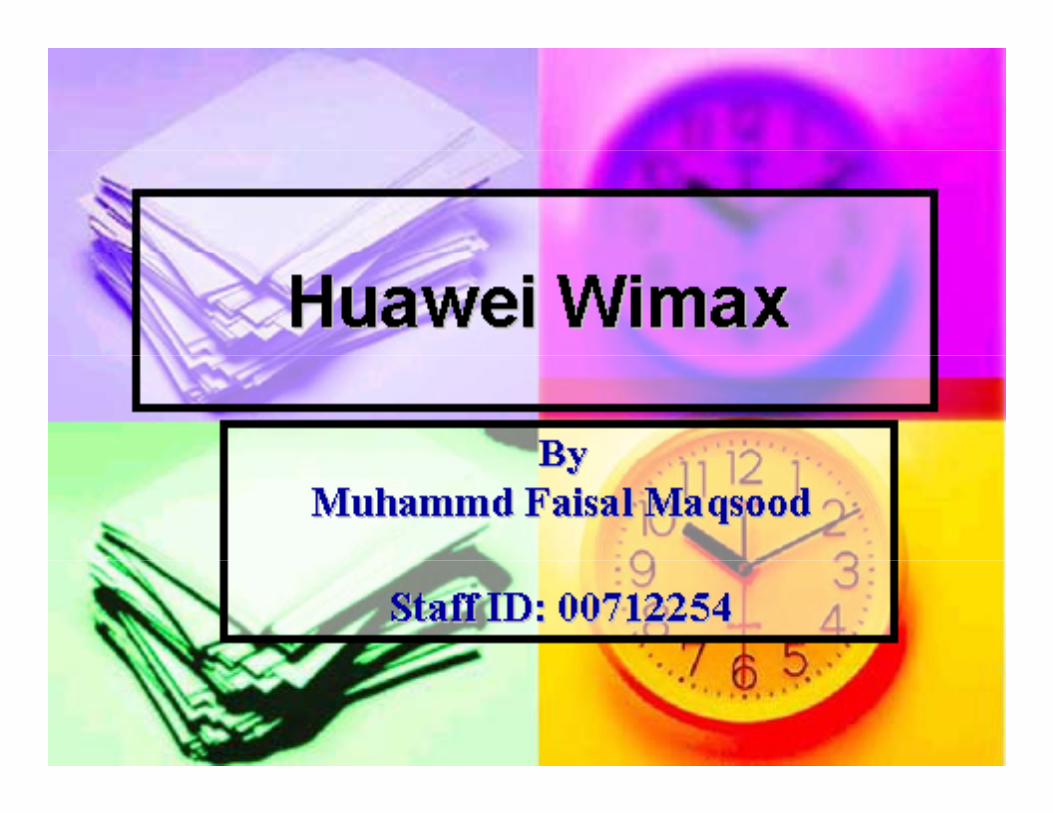
AMC:Adaptive Modulation and Coding Modulation scheme on sub-carrier is changeable.AMC introduced by OFDMA system user different modulation and coding based on the channel condition tomodulation and coding based on the channel condition to provide robust link adaptation in mobile environments.MS under good channel condition can get more higher data rate and average system throughput is also improvedrate and average system throughput is also improved.Channel measurement in 802.16 is based on RSSI and CINR.Mobile WiMAX supports AMC in both downlink and uplink with variable packet size.with variable packet size.
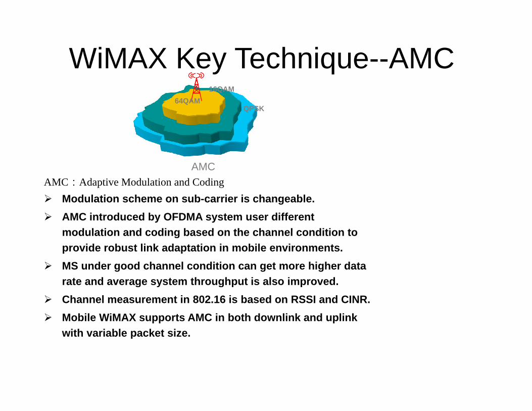
AMC• AMC
– Adaptive Modulation and Coding
AMC
p g• Purpose:
– To select the suitable modulation and coding gmodes according to different channel qualities
16QAM QPSK64QAM

• Through the combination of modulation and• Through the combination of modulation and coding, the network can provide different transmission rate.Th t f h l lit i b d• The measurement of channel quality is based on RSSI and CINR in 802.16e.
• Higher data rate of single user and the higherHigher data rate of single user and the higher average transmission rate of whole network
• Lower interferences.
The selection principle• Good channel quality: combination of high• Good channel quality: combination of high
efficiency modulation mode• Bad channel quality: combination of low
ffi i d l ti defficiency modulation mode

Different Result Based on Different Edge Rate Requirement
>10Mb
Rate Requirement
>1Mbps>10Mbps
>5Mbps500Kbps
VoIP
• The Area close to the BTS, can get high data rateThe Area close to the BTS, can get high data rate• It is not everywhere have a high data rate, in the data coverage planning
It is prefer to deploy the site in the central of the subscribersIt is prefer to deploy the site in the central of the subscribers.

Modulation and Coding Mode inModulation and Coding Mode in WiMAX
Supported Modulations and Codings
DL ULModulation Types
DL UL
QPSK、16QAM、64QAM
QPSK、16QAM、64QAM
CC 1/2, 2/3, 3/4, 5/6 1/2, 2/3, 3/4, 5/6
CTC 1/2 2/3 3/4 5/6 1/2 2/3 3/4 5/6CTC 1/2, 2/3, 3/4, 5/6 1/2, 2/3, 3/4, 5/6
Repetition x2, x4, x6 x2, x4, x6

QoS Guarantee
Mobile WiMAX can meet QoS requirements for a wide range of data q gservices and applications.
In the Mobile WiMAX MAC layer, QoS is provided via service flows.
The QoS parameters define the transmission ordering and scheduling on the air interface. The connection-oriented QoS therefore, can provide accurate control over the air interface.

QoS-Based Services
Unsolicited Grant Service (UGS) – VoIP (without silence suppression)Unsolicited Grant Service (UGS) – VoIP (without silence suppression)
Extended Real-time Polling Service (ertPS) – VoIP with silence
suppression
Real-time Polling Service (rtPS) – MPEG video
Non-real-time Polling Service (nrtPS) – FTP service
Best Effort (BE) – network browse, e-mail

Services WiMAX Supported
WiMAX forum put forward following service need to support:
pp
p g pp
• Interactive games among multiple person
• VoIP and video meeting
• Media streaming downloading
• Web browse and instant messages
• Media matter downloading

Target Market
• Nomadic• Fixed • Simple Mobility
• Portable • Full Mobility
Fixed Nomadic Portable Simple Mobility Full MobilityFixed(16d/16e)
Nomadic(16e)
Portable(16e)
Simple Mobility(16e)
Full Mobility(16e)
ApplicationEnterprise access Backhaul、high-level family outdoor access
Family indoor access and personal terminal access(not support handover)
Family outdoor access and personal terminal access( support handover )
Middle-rate mobile personal terminal
access
High-rate mobile personal terminal access
Terminal Outdoor Indoor, PCMCIAIndividual CPE,PCMCIA,Embedded portable terminal
Individual CPE,PCMCIA ,Personal handing terminal ,Embedded handing terminal
Mobility N/A Not support >5Km/h, >60Km/h >120Km/h
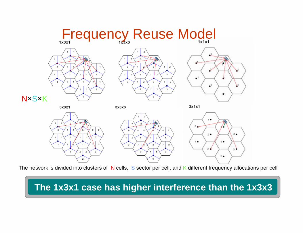
Frequency Reuse Model
N×S×K
The network is divided into clusters of N cells, S sector per cell, and K different frequency allocations per cell
The 1x3x1 case has higher interference than the 1x3x3The 1x3x1 case has higher interference than the 1x3x3

PUSC 1*3*1PUSC : There is 1 frequency point F1 in the whole network The DL and UL uses
11 11
PUSC : There is 1 frequency point F1 in the whole network. The DL and UL uses PUSC permutation models.
F1F133
2233
22
Only 1 Frequency Point for whole network, easy for Soft-Handover
Lower Frequency Efficiency11
33
q y yLarger CoverageEasy Deployment
More Interference Consideration22 More Interference Consideration
Reuse = 3

PUSC with all SC 1*3*3/FUSC 1*3*3PUSC with all SC/FUSC: There are 3 frequency points F1, F2, F3. Each sector of site with 3 sectors uses one frequency respectively. The DL uses FUSC/PUSC with all SC, and UL uses PUSC with all SC permutation models.
F1F1 F1F1 High Capacity per SiteLower Interference
F3F3F2F2
F3F3F2F2
F1F1
Lower InterferenceLarger CoverageEasy Deployment
F1F1
F3F3F2F2
Need Frequency Resource
F3F3

FFR 1*3*1FFR: Fractional Frequency Reuse, The PUSC will be used in the area beyond BS to ensure the coverage and the core area of the cells will use the PUSC with all SC permutation to enhance the throughput
Only 1 Channel for whole network, easy for Soft-Handovereasy for Soft Handover
Higher Frequency efficiencyLarger throughput per sector
Higher Frequency Efficiency

Different Result Based on Different Morphology
Dense UrbanCit t d CBD hi h d it lti l
Morphology
City center and CBD, high density multiple dwelling residential units, challenging propagation environment
UrbanSurrounding the city center, moderate to high density, Squally challenging propagation environment
SuburbanSuburbanLower density, favorable propagation environment
RuralMoving further from the city center, homes are g y ,further apart resulting in significantly lower population density with scattered small businesses

Coverage Planning Case StudyLink Budget
• Morphology: Dense Urbanp gy• Terminal: Indoor PCMCIA• Edge modulation: QPSK1/2• Frequency:2.5G• BS height: 30m• BS height: 30m• Propagation:Cost231-Hata ( HW )• MIMO: Matrix A• Antenna: UL 1T2R/DL 2T1R• Result: UL 0.55km/DL 0.47km• WiMAX radius is limited by UL

Capacity Planning Steps
Traffic model analysis/ requirement analysis/ requirement analysis
Single-user Customer resourceSingle user capacity
Customer resourcenetworking analysis
Single-sitecapacity
Total throughput
Number of sites

Significance of radio Propagation Models
The propagation models are the basis of coverage planning. Good models ensure the
i i f l iprecision of planning.The radio propagation modules are affected
by the system working frequency. Different models have different working frequency ranges, and the ranges differ for indoor propagation models and outdoor propagation models.
When using the propagation models, pay attention to the value set for each parameter.attention to the value set for each parameter.

What is MIMO?• MIMO: Multiple input and
multiple outputmultiple output

Multiple Antenna Technologies Analysis MIMO Matrix-A
User1
STT
Supported to provide transmit diversity and reduce fading margin by 2-8 dB depending on the environment &terminal
UL DL SS 1
Dthe environment &terminal antenna number
1T2R 2T2R
• Compare with SISO,MIMO 2×2 can improve the coverage radius by 50%~90% (Huawei simulation result)
I BS t th h t i di tl1T1R
800 MHZ
1T2R 2T2R • Improve BS system throughput indirectly(20%,Huawei simulation result)
• Support fixed and mobile service
• One dual-polarization antenna can support 2T2R
1T1R
• One dual-polarization antenna can support 2T2R MIMO
• Can support single or dual antenna terminal

Multiple Antenna Technologies Analysis MIMO Matrix-B
S ti l M lti l i
User1
Spatial Multiplexing
With 2x2 MIMO, the DL user and sector peak data rate are User1
SS 1
ptheoretically doubled. But 1.6times than SISO is realizable.
• SM: Each signal may convey different data to the same or different users, increasing the capacity. Rx antenna can not be less than Tx antenna. For terminal must have 2 Rx antennas
• Sector throughput, peak data rate and spectrum efficiency can be improved
• UL collaborative SM (Virtual MIMO) can not increase the peak data rate of users, but can improve the UL sector throughput (about 33%, compare with 1T2R, from WiMAX Forum)

Working Mode of MIMO• Diversity mode(Matrix A)
T it th d t i diff t t
g
– Transmit the same data in different antennas
– Enhance the capacity indirectly
Th b f i i t b l th th– The number of receiving antenna can be less than the number of transmitting antennas
• Spatial Multiplexing mode (Matrix B)Spatial Multiplexing mode (Matrix B)
– Transmit different data in different antennas
– Enhance the capacity directlyEnhance the capacity directly
– The number of receiving antenna can not be less than the number of transmitting antennas

Multiple Antenna Technologies Analysis MIMO-BF
• Based on not only DOA, but also spatial signature of different users
• Can use not only in urban but also in suburban & rural
• Use non-correlation antenna array, can be applied to NLOS area
MIMO M t i A/B/C d t MIMO BF• MIMO Matrix A/B/C can upgrade to MIMO-BF
• MIMO-BF 2*2 can obtain additional 3dB coverage gain compare with MIMO-Matrix A , and MIMO-BF 4*4 can obtain 6dB (Huawei theory research result)

What is AAS?• AAS: Adaptive/Advanced Antenna
S
What is AAS?
System
Omni antenna Directional antenna AAS

Types of AAS
• Switched Beam
Types of AAS
Antennas– Cell is covered by
some fixed beams
• Adaptive A t AAntenna Arrays– Beam can trace
th ’ itithe user’s position automatically

Improvement to performance
Increase the SNR and the sensitivity of BS
Improvement to performance
Decrease the error bit of systemDecrease the system interferenceyEnhance the coverageImprove the spectrum efficiency.p p y

Multiple Antenna Technologies Analysis Adaptive Antenna System (AAS)
UserUser
Switched Beam systemAdaptive Array systemBecause of Muti path in Urban AAS
• Based on DOA (Direction Of Arrival)• AAS include switched beam system and adaptive array system
Because of Muti-path in Urban, AAS coverage gain is lower than LOS
• Increase coverage and capacity by beamforming
• AAS can obtain 3.5dB coverage gain in rural, 3dB in suburban and only 2.55dB in urban
• AAS does not deal well with mobility at higher speeds