Embed Size (px)
Citation preview
���������
�������������������������������� ������������
��������������������
S7-400, M7-400 Programmable Controllers
This Supplement contains additional information about the products. It is a separate component andshould be considered more up-to-date than the information in the manuals and catalogs if uncertaintiesarise.

� !'"���$���������#� �����������$#���#�"&��
���������� ��������������
�� �� ������������ ����������������� ���� ���������� ������ �������� ���� ������� ����� ���������� �� �������� ���������!����� �� �������� ���� �������� ��������������������������������� � ��!��� ������������ ��������������������!���� ����� ������� �� � �� ��
� ��� ��� �� ���� ����� ����������������������� � ���������� ������ ��������� �� ���� ������� �� �������������� ��� ���� �� ���� �!��� ������ ����� � ����� �� � ���� ��� � ��� �� � ��� ��� ����� ����� � � �� � �� � �����!� ��� �!� � � ���!� ���� ������� ������ �� ��� ��� �� �� ������������� ����������������� � ���� �� ���� ��
� ������������� ���������� �
��#������"� ���������$'
Siemens AGBereich Automatisierungs- und AntriebstechnikGeschaeftsgebiet Industrie-AutomatisierungssystemeOestliche Rheinbrueckenstr. 50 76181 Karlsruhe
�����"�����"������� ������ ������� �������������!

S7-400, M7-400Supplement to the Documentation
3S7-400, M7-400 Programmable ControllersC79000-Z7076-C417-06
������� � �� �������� � ��
Contents
1 Connecting the Central Rack (CR) and the Expansion Rack (ER) 4. . . . . . . . . . . . . .
2 Special Features of STEP 7 Programming with CPUs 41x 5. . . . . . . . . . . . . . . . . . . .
3 Cycle and Reaction Times of the S7-400 8. . . . . . . . . . . . . . . . . . . . . . . . . . . . . . . . . . . .
4 Special Features of Communication 11. . . . . . . . . . . . . . . . . . . . . . . . . . . . . . . . . . . . . . . .
5 Behavior of S7-400 Signal Modules After Parameter Assignment 13. . . . . . . . . . . . .
6 PROFIBUS DP Master Interface IM 467 14. . . . . . . . . . . . . . . . . . . . . . . . . . . . . . . . . . . . . .
7 PS 407 10A (0KA00) Power Supply Module 17. . . . . . . . . . . . . . . . . . . . . . . . . . . . . . . . . .
8 PS 407 10A (0KA01) and PS 407 10A R Power Supply Modules 17. . . . . . . . . . . . . . .
9 SM 421 Digital Input Module;DI 32xDC 24 V 17. . . . . . . . . . . . . . . . . . . . . . . . . . . . . . . . .
10 Points to Note when Installing a Synchronization Submodule 17. . . . . . . . . . . . . . . .
11 SM 431 Analog Input Module;AI 16 x 13 Bit (6ES7431-0HH00-0AB0) 19. . . . . . . . . . .
The information in this supplement regarding the properties of CPUs relates to thefollowing CPUs with their specified release levels.
CPU Order Number From Release Level
CPU 412-1 6ES7 412-1XF02-0AB0 02
CPU 413-1 6ES7 413-1XG02-0AB0 01
CPU 413-2 DP 6ES7 413-2XG02-0AB0 01
CPU 414-1 6ES7 414-1XG02-0AB0 02
CPU 414-2 DP, 128 Kbytes 6ES7 414-2XG02-0AB0 02
CPU 414-2 DP, 384 Kbytes 6ES7 414-2XJ01-0AB0 02
CPU 416-1 6ES7 416-1XJ02-0AB0 02
CPU 416-2 DP, 0.8 Mbytes 6ES7 416-2XK01-0AB0 02
CPU 416-2 DP, 1.6 Mbytes 6ES7 416-2XL01-0AB0 02
CPU 417-4 6ES7 417-4XL00-0AB0 01
CPU 417-H 6ES7 417-4HL00-0AB0 01

S7-400, M7-400 Supplement to the Documentation
S7-400, M7-400 Programmable ControllersC79000-Z7076-C417-064
1 Connecting the Central Rack (CR) and the Expansion Rack (ER)
EXTF LED on the IM 461-x
On an expansion rack (ER) connected to a central rack (CR) via an IM 460-3/IM461-3 (remote link), the EXTF LED on the receiving IM 461-3 lights up when theCR is switched off.
ON an ER connected to a CR via an IM 460-0/IM 461-0 or IM 460-1/IM 461-1 (locallink), the EXTF LED on the receive IM does not light up when the CR is switchedoff.
Interference Suppression Measures
To conform to the requirements of the EC Directive 89/336/EEC “ElectromagneticCompatibility” (CE mark), you should take the following measures when connectingcentral racks and expansion racks:
� Remote connection of expansion rack to a central rack with mounting rack URvia IM 460-0/IM 461-0:
Attach a ferrule (split ferrite core) close to each connector on the IM cable
A suitable split ferrite core is that of the type SFC 10 by Thora, Winn 6,D-91567 Herrieden, Germany Tel. +49 9825 4755 or a comparable product.
Figure 1-1 shows an IM cable with a ferrule (split ferrite core).
Ferrule (Split Ferrite Core)
Figure 1-1 IM Cable with Ferrule (Split Ferrite Core)
S7-400, M7-400Supplement to the Documentation
5S7-400, M7-400 Programmable ControllersC79000-Z7076-C417-06
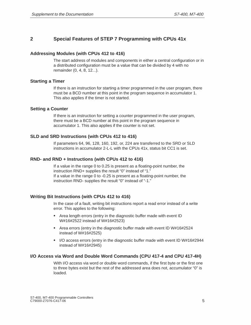
2 Special Features of STEP 7 Programming with CPUs 41x
Addressing Modules (with CPUs 412 to 416)
The start address of modules and components in either a central configuration or ina distributed configuration must be a value that can be divided by 4 with noremainder (0, 4, 8, 12...).
Starting a Timer
If there is an instruction for starting a timer programmed in the user program, theremust be a BCD number at this point in the program sequence in accumulator 1.This also applies if the timer is not started.
Setting a Counter
If there is an instruction for setting a counter programmed in the user program,there must be a BCD number at this point in the program sequence inaccumulator 1. This also applies if the counter is not set.
SLD and SRD Instructions (with CPUs 412 to 416)
If parameters 64, 96, 128, 160, 192, or, 224 are transferred to the SRD or SLDinstructions in accumulator 2-L-L with the CPUs 41x, status bit CC1 is set.
RND- and RND + Instructions (with CPUs 412 to 416)
If a value in the range 0 to 0.25 is present as a floating-point number, theinstruction RND+ supplies the result “0” instead of “1.”If a value in the range 0 to -0.25 is present as a floating-point number, theinstruction RND- supplies the result “0” instead of “-1.”
Writing Bit Instructions (with CPUs 412 to 416)
In the case of a fault, writing bit instructions report a read error instead of a writeerror. This applies to the following:
� Area length errors (entry in the diagnostic buffer made with event IDW#16#2522 instead of W#16#2523)
� Area errors (entry in the diagnostic buffer made with event ID W#16#2524instead of W#16#2525)
� I/O access errors (entry in the diagnostic buffer made with event ID W#16#2944instead of W#16#2945)
I/O Access via Word and Double Word Commands (CPU 417-4 and CPU 417-4H)
With I/O access via word or double word commands, if the first byte or the first oneto three bytes exist but the rest of the addressed area does not, accumulator “0” isloaded.

S7-400, M7-400 Supplement to the Documentation
S7-400, M7-400 Programmable ControllersC79000-Z7076-C417-066
Access to D P Slaves (with CPUs 412 to 416)
A DP station is connected to an S7-400 via an external DP interface moduleCP 443-5.
If you use word access to access a DP slave with one byte of user data(instructions L PIW, T PQW), the I/O access error organization block (OB122) is notcalled. After executing the instruction L PIW, accumulator 1 contains B#16#00instead of the non-existent peripheral byte.
If you use double word access to access a DP slave with three bytes of user data(instructions L PID, T PQD), the I/O access error organization block (OB122) is notcalled. After executing the instruction L PID, accumulator 1 contains B#16#00instead of the non-existent peripheral byte.
Single Step (with CPUs 412 to 416)
With the STEP 7 function “single step mode,” the CPU requires more time than theexecution time for the instruction. As a result of the scan cycle time monitoring, it ispossible that the CPU may go into STOP mode because the cycle time wasexceeded. You can avoid this by calling the SFC43 “RE_TRIGR” in the time errororganization block (OB80).
Breakpoints (with CPUs 412 to 416)
If you have set a breakpoint at a jump instruction or a block end instruction and theCPU has reached this instruction, neither the function “execute next statement” northe function “execute call” can be executed. Instead the error message “D063:Resource error: the trigger event is occupied” is displayed.
If you have set a breakpoint at a UC or CC instruction and the CPU has reachedthis instruction, the function “execute call” cannot be executed. Instead the errormessage “D063: Resource error: the trigger event is occupied” is displayed.
Remedy: Delete the current breakpoint or move it to the previous command line.
SFC 11 SYNC/FREEZE
SFC11 cannot be called in the startup OBs (OB100, OB101). A call in these OBs isrejected with the RET_VAL identifier 0x80C8. In the other priority classes, you canuse SFC11 without restrictions. You can use SFC11 only for the plug-in DPmodules (CP 443-5 extended, IM 467). SFC11 cannot be used for the integratedDP interfaces of the CPU 413-2, 412-2, and 416-2.
ET 200M stations assigned to sync/freeze groups with STEP 7 during hardwareconfiguration must not contain FM or CP modules.
S7-400, M7-400Supplement to the Documentation
7S7-400, M7-400 Programmable ControllersC79000-Z7076-C417-06
Deviation Precision for Time Synchronization
The deviation precision during time synchronization is:
At the communication bus 10 ms
At the MPI 200 ms
Accuracy of the Integrated Real-Time Clock
The accuracy of the integrated real-time clock is:
During operation 8.6 s/d
With battery backup 1.7 s/d
SFC 90 Not Released (CPU 417-4H)
SFC 90 has not yet been released for use with CPU 417-4H.
FM 353/354 Not Distributed (CPU 417-4 and CPU 417-4H)
If you use the CPU 417 as the DP master, you must not use FM 353 and 354 in adistributed configuration within an ET 200M. This applies to:
� FM 353, up to and including 6ES7 353-1AH01-0AE0, firmware version 3.3
� FM 354, up to and including 6ES7 354-1AH01-0AE0, firmware version 3.3
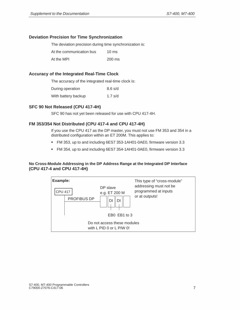
No Cross-Module Addressing in the DP Address Range at the Integrated DP Interface(CPU 417-4 and CPU 417-4H)
This type of “cross-module”addressing must not beprogrammed at inputsor at outputs!
CPU 417
PROFIBUS DP
DP slavee.g. ET 200 M
DI DI
EB0 EB1 to 3
Do not access these moduleswith L PID 0 or L PIW 0!
Example:

S7-400, M7-400 Supplement to the Documentation
S7-400, M7-400 Programmable ControllersC79000-Z7076-C417-068
3 Cycle and Reaction Times of the S7-400
Introduction
The times and measured values listed below can be used in conjunction with theinformation provided in the Module Specifications Reference Manual to calculatethe cycle and reaction times.
Test Arrangement
CPU 417-4/CPU417-4H with DI 16 (421-7DH00-0AB0) and DO 32(422-1BL00-0AA0) in the central rack.
Operating System Processing Times of the CPUsSequence CPU 417-4 CPU 417-4H CPU 417-4H
Solo Redundant
Cycle control 150 – 290 �s 1)
∅ 152 �s190 – 1770 �s 2)
∅ 200 �s395 – 1865 �s 3)
∅ 445 �s
1. The update of the timer cells increases the cycle time by approximately 140 �severy 10 ms.
2. The update of the timer cells increases the cycle time by approximately 420 �severy 10 ms.The double master detection increases the cycle time by approximately 1070 �severy 200 ms.
3. The update of the timer cells increases the cycle time by approximately byapproximately 460 �s every 10 ms.

S7-400, M7-400Supplement to the Documentation
9S7-400, M7-400 Programmable ControllersC79000-Z7076-C417-06
Updating the Process Image of the CPUs
Parts CPU 417-4 CPU 417-4H CPU 417-4HSolo Redundant
K Basic load 20 �s 20 �s 20 �sA In the central rack
Read byte/word/double wordWrite byte/word/double wordwith n = 1, 2, or 4
n*1.9 �sn*1.9 �s
13+n*1.9 �s9+n*1.9 �s
48+n*1.9 �s44+n*1.9 �s
B Per byte in expansion unit withlocal linkRead byte/word/double wordWrite byte/word/double wordwith n = 1, 2, or 4
n*5 �sn*5 �s
13+n*5 �s9+n*5 �s
48+n*5 �s44+n*5 �s
C Per byte in expansion unit withremote linkRead byte/word/double wordWrite byte/word/double wordwith n = 1, 2, or 4
n*10 �sn*10 �s
13+n*10 �s9+n*10 �s
48+n*10 �s44+n*10 �s
D In DP area for integrated DPinterface Read byte/word/double wordWrite byte/word/double wordwith n = 1, 2, or 4
n*0.5 �sn*0.5 �s
13+n*0.5 �s9+n*0.5 �s
48+n*0.5 �s44+n*0.5 �s
CPU-Specific Factors
Sequence CPU 417-4 CPU 417-4H CPU 417-4H
Solo Redundant
Factor 1.02 1.03 1.14
Direct Access of the CPUs to I/O Modules
Access Type CPU 417-4 CPU 417-4H CPU417-4H
Solo Redundant
Read byteRead wordRead double wordWrite byteWrite wordWrite double word
2.4 �s3.8 �s7.6 �s2.4 �s3.9 �s7.8 �s
43 �s46 �s50 �s38 �s41 �s45 �s
79 �s82 �s86 �s73 �s76 �s80 �s

S7-400, M7-400 Supplement to the Documentation
S7-400, M7-400 Programmable ControllersC79000-Z7076-C417-0610
Increasing the Cycle Time by Nestin g Interrupts
CPU Hard-ware
Interrupt
Diagnosticinterrupt
Time-of-Day
Interrupt
Time-DelayInterrupt
CyclicInterrupt
Programming/Access Error
417-4 370 �s 420 �s 350 �s 260 �s 260 �s 130 �s / 140 �s
417-4 H Solo 390 �s 450 �s 310 �s 270 �s 255 �s 140 �s / 170 �s
417-4 H Red 705 �s 785 �s 560 �s 530 �s 530 �s 175 �s / 240 �s
CPU Asynchronous error (OB 85 while updating the process image)
417-4 270 �s
417-4H Solo 260 �s
417-4H Redundant 310 �s
Hardware Interrupt Reaction Times of the CPUs
CPU min. max.
417-4 255 �s 435 �s
417-4H Solo 270 �s 530 �s
417-4H Redundant 375 �s 690 �s
Diagnostic Interrupt Reaction Times of the CPUs
CPU min. max.
417-4 310 �s 490 �s
417-4H Solo 325 �s 645 �s
417-4H Redundant 415 �s 780 �s
Reproducibility of Time-Delay Interrupts and Cyclic Interrupts of the CPUs
CPU Reproducibility
Time-Delay Interrupt Cyclic Interrupt
417-4 –770 �s / +330 �s –40 �s / +40 �s
417-4H Solo –750 �s / +400 �s –850 �s / +850 �s
417-4H Redundant –500 �s / +800 �s –700 �s / +700 �s
S7-400, M7-400Supplement to the Documentation
11S7-400, M7-400 Programmable ControllersC79000-Z7076-C417-06
4 Special Features of Communication
Number of Operator Stations
This specifies how many operator stations you can log on to the CPU, for examplefor process control messages.
CPU OS Stations
CPU 412-1 4
CPU 413-1, CPU 413-2 4
CPU 414-1, CPU 414-2 4
CPU 416-1, CPU 416-2 8
CPU 417-4, CPU 417-4H 8
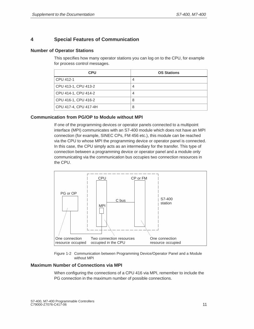
Communication from PG/OP to Module without MPI
If one of the programming devices or operator panels connected to a multipointinterface (MPI) communicates with an S7-400 module which does not have an MPIconnection (for example, SINEC CPs, FM 456 etc.), this module can be reachedvia the CPU to whose MPI the programming device or operator panel is connected.In this case, the CPU simply acts as an intermediary for the transfer. This type ofconnection between a programming device or operator panel and a module onlycommunicating via the communication bus occupies two connection resources inthe CPU.
CPU CP or FM
MPIC bus
PG or OP
Two connection resourcesoccupied in the CPU
S7-400station
One connectionresource occupied
One connectionresource occupied
Figure 1-2 Communication between Programming Device/Operator Panel and a Modulewithout MPI
Maximum Number of Connections via MPI
When configuring the connections of a CPU 416 via MPI, remember to include thePG connection in the maximum number of possible connections.

S7-400, M7-400 Supplement to the Documentation
S7-400, M7-400 Programmable ControllersC79000-Z7076-C417-0612
PG AccessA CPU exchanges data with other systems using communication mechanisms, forexample with other programmable controllers, with operator interface stations (OP,OS) or with programming devices (see Figure 1-3).
CPU
SIMATIC NET
MPI
PG OS PLC
PG OS SlavePG OS PLC
DP network
Figure 1-3 Data Exchange
Process communication, including communication services for data exchangebetween programmable controllers (PLC – PLC) and between programmablecontrollers and operator interface stations (PLC – OS/OP), has priority in CPUsover communication between programming devices and CPUs.The CPUs have different characteristics. One of these characteristics is theircommunication performance. If the communication resources of a CPU areoccupied completely by process communication, this can severely hamper accessto the CPU from the programming device.This can often be avoided by a slight reduction in process communication. Thefollowing table shows several examples of this. The values relate to a user datalength of 200 bytes.
CommunicationM h i
CPU 412, CPU 413 CPU 414, CPU 416Mechanism Max. No. of
FramesMax. No. ofFrames withReliable PG
Access
Max. No. ofFrames
Maximum No. ofFrames withReliable PG
Access
PLC–PLC communicationwith USEND/URCV
140 / s 130 / s 150 / s 140 / s
PLC–PLC communicationwith BSEND/BRCV
100 / s 90 / s 100 / s 90 / s
PLC–PLC communicationwith AGSEND/RCV *
70 / s 65 / s 70 / s 65 / s
PLC-OP communication(single jobs)
65 / s 60 / s 80 / s 60 / s
* It is advisable to set a minimum scan cycle time of 10 ms or to locate thecalls in a cyclic interrupt priority class.
The number of frames per line reflects the performance of the CPU.
S7-400, M7-400Supplement to the Documentation
13S7-400, M7-400 Programmable ControllersC79000-Z7076-C417-06
5 Behavior of S7-400 Signal Modules After Parameter Assignment
Parameter Assignment of S7-400 Signal Modules
S7-400 signal modules can be assigned parameters by the operating system of theCPU or by calling an SFC in your program.
Parameters are assigned by the operating system of the CPU in the followingcases:
� At startup (both complete restart and hot restart)
� After plugging a module into a configured slot
� After the return of a rack or station when using distributed I/Os
S7-400 Input Modules
After assigning parameters to an S7-400 input module, the data read by yourprogram from the module are not immediately valid. You can only evaluate thesewhen bit 2 (“operating status”) in byte 2 of diagnostic data record 0 has the value 0(“RUN”).
For this reason, all S7-400 input modules which can be assigned parametersprovide diagnostic data record 0. You can read out diagnostic data record 0 withSFC51 “RDSYSST” (input parameter SZL_ID W#16#00B1) or with SFC59“RD_REC”.
S7-400 Output Modules
After assigning parameters to an S7-400 output module, it is possible that theoutput data you have written to the module is not transferred immediately to theoutputs.
From the time that bit 2 (“operating status”) in byte 2 of diagnostic data record 0 isset to the value 0 (“RUN”), the module transfers the output data to the outputterminals.
For this reason, diagnostic data record 0 is provided by all S7-400 output moduleswhich can be assigned parameters. You can read out diagnostic data record 0 withSFC51 “RDSYSST” (input parameter SZL_ID W#16#00B1) or with SFC59“RD_REC.”
S7-400, M7-400 Supplement to the Documentation
S7-400, M7-400 Programmable ControllersC79000-Z7076-C417-0614
6 PROFIBUS DP Master Interface IM 467
Order Number
6ES7 467-5GJ00-0AB0
Use
PROFIBUS DP, standardized according to EN 50170, allows fast communication inthe field area between programmable logic controllers, PCs, and field devices.Field devices include distributed I/O devices (ET 200), drives, valve islands,switching devices, and many others.
The IM 467 interface module is intended for use in an S7-400 programmable logiccontrol system. It enables you to connect an S7-400 to PROFIBUS DP.
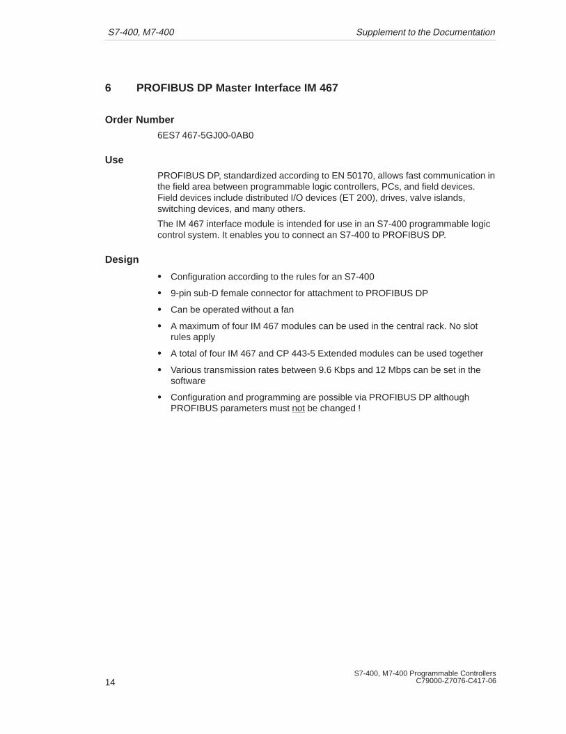
Design
� Configuration according to the rules for an S7-400
� 9-pin sub-D female connector for attachment to PROFIBUS DP
� Can be operated without a fan
� A maximum of four IM 467 modules can be used in the central rack. No slotrules apply
� A total of four IM 467 and CP 443-5 Extended modules can be used together
� Various transmission rates between 9.6 Kbps and 12 Mbps can be set in thesoftware
� Configuration and programming are possible via PROFIBUS DP althoughPROFIBUS parameters must not be changed !

S7-400, M7-400Supplement to the Documentation
15S7-400, M7-400 Programmable ControllersC79000-Z7076-C417-06
PROFIBUS DP interface9-pin sub-D
LED displays
Mode switch
Figure 1-4 Configuration of the IM 467
Communication Services
The IM 467 provides you with two possible means of communication:
� PROFIBUS-DP
The IM 467 is a PROFIBUS DP master which conforms to EN 50 170. It isconfigured completely with STEP 7. In principle, its behavior is the same as thatof the integrated PROFIBUS DP interfaces on the CPU modules (fordifferences, refer to the technical data of the IM 467).
No function calls are necessary in the STEP 7 user program for DPcommunication.
� S7 functions
S7 functions ensure optimum, simple communication in a SIMATIC S7/M7/C7automation system. For IM 467, the following S7 functions are used:
– Programming device functions via PROFIBUS DP
– Operator monitoring and control functions via PROFIBUS DP
Communication requires no further configuration on the IM 467.
The S7 functions can be used alone or parallel to the PROFIBUS DP protocol. Ifthey are used parallel to DP communication, this will affect the PROFIBUS DPround-trip time.
S7-400, M7-400 Supplement to the Documentation
S7-400, M7-400 Programmable ControllersC79000-Z7076-C417-0616
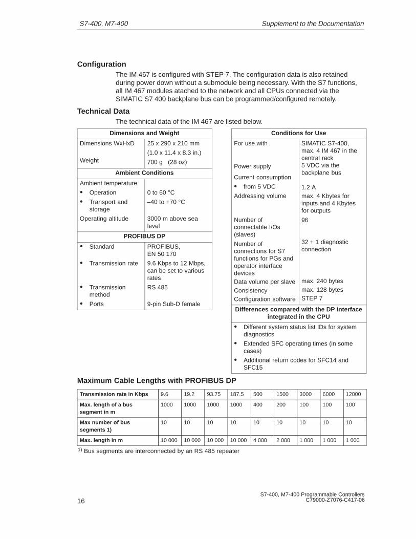
ConfigurationThe IM 467 is configured with STEP 7. The configuration data is also retainedduring power down without a submodule being necessary. With the S7 functions,all IM 467 modules atached to the network and all CPUs connected via theSIMATIC S7 400 backplane bus can be programmed/configured remotely.
Technical DataThe technical data of the IM 467 are listed below.
Dimensions and Weight
Dimensions WxHxD
Weight
25 x 290 x 210 mm
(1.0 x 11.4 x 8.3 in.)
700 g (28 oz)
Ambient Conditions
Ambient temperature
� Operation
� Transport andstorage
Operating altitude
0 to 60 °C–40 to +70 °C
3000 m above sealevel
PROFIBUS DP
� Standard
� Transmission rate
� Transmissionmethod
� Ports
PROFIBUS, EN 50 170
9.6 Kbps to 12 Mbps,can be set to variousrates
RS 485
9-pin Sub-D female
Conditions for Use
For use with
Power supply
Current consumption
� from 5 VDC
Addressing volume
Number ofconnectable I/Os(slaves)
Number ofconnections for S7functions for PGs andoperator interfacedevicesData volume per slaveConsistencyConfiguration software
SIMATIC S7-400,max. 4 IM 467 in thecentral rack5 VDC via thebackplane bus
1.2 Amax. 4 Kbytes forinputs and 4 Kbytesfor outputs
96
32 + 1 diagnosticconnection
max. 240 bytesmax. 128 bytesSTEP 7
Differences compared with the DP interfaceintegrated in the CPU
� Different system status list IDs for systemdiagnostics
� Extended SFC operating times (in somecases)
� Additional return codes for SFC14 andSFC15
Maximum Cable Lengths with PROFIBUS DP
Transmission rate in Kbps 9.6 19.2 93.75 187.5 500 1500 3000 6000 12000
Max. length of a bussegment in m
1000 1000 1000 1000 400 200 100 100 100
Max number of bussegments 1)
10 10 10 10 10 10 10 10 10
Max. length in m 10 000 10 000 10 000 10 000 4 000 2 000 1 000 1 000 1 000
1) Bus segments are interconnected by an RS 485 repeater

S7-400, M7-400Supplement to the Documentation
17S7-400, M7-400 Programmable ControllersC79000-Z7076-C417-06
7 PS 407 10A (0KA00) Power Supply Module
The PS 407 10A (0KA00) power supply module cannot be used redundantly. At thepresent time only the PS 407 10A R power supply module with the order number6ES7 407 0KR00 0AA0 can be used redundantly.
8 PS 407 10A (0KA01) and PS 407 10A R Power Supply Modules
The power supply modules have an inrush current limitation in accordance withNAMUR. When you switch off the supply voltage or disconnect the power supplymodule from the mains, you no longer have to wait approximately 20 secondsbefore switching the supply voltage on again. The inrush current limitation of thepower supply module is always guaranteed to be fully effective.
9 SM 421 Digital Input Module;DI 32xDC 24 V
Order Number
6ES7 421-1BL00-0AA0
Extended Function from Release Level 03
The lower limit of the nominal input range for the signal “0” has been extendedfrom -3 V to -30 V.
This means that the nominal input voltage for signal “0” is –30 V to 5 V.
10 Points to Note when Installing a Synchronization Submodule
Issuing the Rack Number
In order to differentiate between the two part systems in an H system, the CPUsmust also be able to issue the rack number. One CPU has the rack number 0, theother CPU has the rack number 1. You set the rack numbers on thesynchronization submodule. For this purpose there is a miniature sliding switch onthe submodule with three settings. The rack number is adopted following Power Onand a manual memory reset.

S7-400, M7-400 Supplement to the Documentation
S7-400, M7-400 Programmable ControllersC79000-Z7076-C417-0618
Inserting and Removing the Synchronization Module with Voltag e Applied
When inserting or removing a synchronization module in a H system, you do notneed to switch off the power supply (PS). The synchronization module has asecond front cover which you must unscrew before you remove the module (themodule cannot be removed while the cover is in place). When you have unscrewedthis front cover, the synchronization module is isolated from the voltage and youcan remove it without damage. When you insert the submodule, it is onlyconnected to the voltage when you screw the front panel into place again (seefollowing figure).
Switch for setting
the rack numberAdditional front cover

S7-400, M7-400Supplement to the Documentation
19S7-400, M7-400 Programmable ControllersC79000-Z7076-C417-06
11 SM 431 Analog Input Module;AI 16 x 13 Bit(6ES7431-0HH00-0AB0)
Order Number
6ES7 431-0HH00-0AB0
Characteristics
The SM 431;AI 16 x 13 Bit has the following characteristics:
� 16 inputs for current/voltage measurement
� Resolution13 bits
� Non-isolated (no isolation between bus section and analog section)
� Permissible common-mode voltage 2 VDC/VAC

S7-400, M7-400 Supplement to the Documentation
S7-400, M7-400 Programmable ControllersC79000-Z7076-C417-0620
Terminal Connection Diagram of the SM 431;AI 13 x 16 Bit
Voltage measurementCurrent measurement
M1+
M2–
M3–
M4–
M5–
M6–
M7–
CH0
CH1
CH2
CH3
CH4
CH5
CH6
CH7
L+
M0+M0–
M1–
M2+
M3+
M4+
M5+
M6+
M7+
M
M8–
M9–
M8+
M9+
M10–
M11–
M10+
M11+
M12–
M13–
M12+
M13+
M14–
M15–
M14+
M15+
CH8
CH9
CH10
CH11
CH12
CH13
CH14
CH15
Word 0
Word 4
Word 8
Word 12
Word 16
Word 20
Word 24
Word 28
Word 2
Word 6
Word 10
Word 14
Word 18
Word 22
Word 26
Word 30
L+
M
293031323334353637
39404142434445464748
38
123456789
10111213141516171819202122232425262728
Tr
Tr
Tr
Tr
Tr
Tr
Tr
Tr
Figure 1-5 Terminal Connection Diagram of the Analog Input Module SM 431;AI 16 x 13 Bit
S7-400, M7-400Supplement to the Documentation
21S7-400, M7-400 Programmable ControllersC79000-Z7076-C417-06
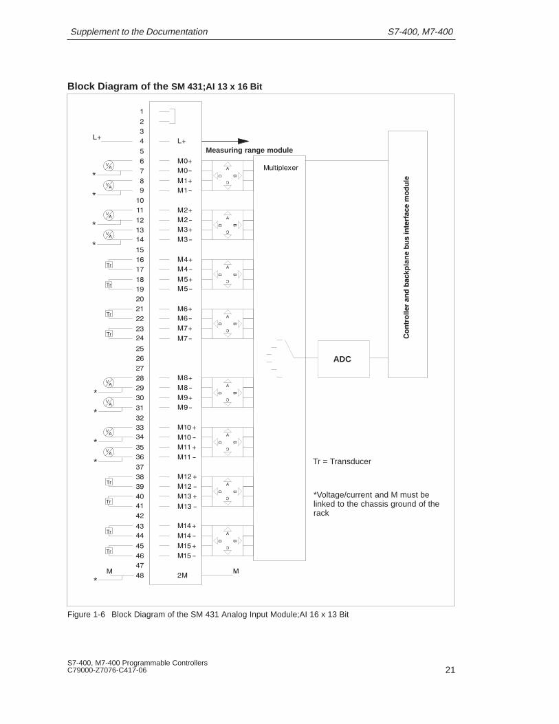
Block Diagram of the SM 431;AI 13 x 16 Bit
Tr
Tr
Tr
Tr
Tr
Tr
Tr
Tr
*
*Voltage/current and M must belinked to the chassis ground of therack
Tr = Transducer
*
*
*
*
*
*
*
*
Measuring range module
ADC
Figure 1-6 Block Diagram of the SM 431 Analog Input Module;AI 16 x 13 Bit

S7-400, M7-400 Supplement to the Documentation
S7-400, M7-400 Programmable ControllersC79000-Z7076-C417-0622
Adapting to Different Sensors
To adapt the analog input module to different sensors, follow the steps outlinedbelow:
1. Insert the measuring range module into the module. One measuring rangemodule adapts two inputs channels to a sensor type.
2. Set the relevant measuring range for the channels of the module when you setthe module parameters.
Using the Measuring Range Modules
With the measuring range modules supplied, you can adapt two successive inputchannels or one resistance channel to one sensor type.
The following table shows the assignments of individual measuring range modulepositions to the relevant sensor types.
Position Sensor Types
A Voltage sensors; � 1 V
B Voltage sensors; 1 to 5 V, � 10 V
C Current sensors;�20 mA, 4 to 20 mA4-wire transducer with current output
D 2-wire transducer; 4 to 20 mATo apply current to these transducers, you must connect 24 Vto the front connector terminals L+ and M.
!WarningThe module can be damaged.The shunt resistance of an input channel can be destroyed if you accidentallyconnect a voltage sensor to the channel and you set the measuring range moduleto position C (current/4-wire transducer).Please make sure that the measuring range module is in the correct positionbefore you connect a sensor to the module.
S7-400, M7-400Supplement to the Documentation
23S7-400, M7-400 Programmable ControllersC79000-Z7076-C417-06
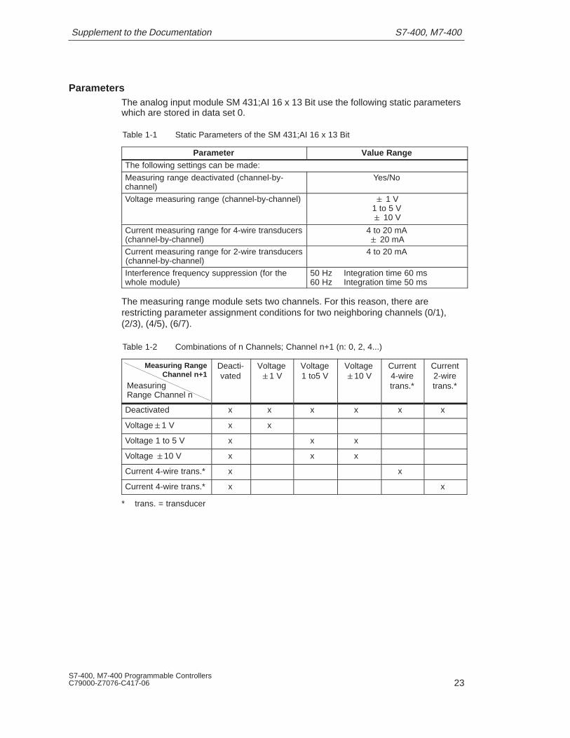
ParametersThe analog input module SM 431;AI 16 x 13 Bit use the following static parameterswhich are stored in data set 0.
Table 1-1 Static Parameters of the SM 431;AI 16 x 13 Bit
Parameter Value RangeThe following settings can be made:
Measuring range deactivated (channel-by-channel)
Yes/No
Voltage measuring range (channel-by-channel) � 1 V1 to 5 V� 10 V
Current measuring range for 4-wire transducers(channel-by-channel)
4 to 20 mA� 20 mA
Current measuring range for 2-wire transducers (channel-by-channel)
4 to 20 mA
Interference frequency suppression (for thewhole module)
50 Hz Integration time 60 ms60 Hz Integration time 50 ms
The measuring range module sets two channels. For this reason, there arerestricting parameter assignment conditions for two neighboring channels (0/1),(2/3), (4/5), (6/7).
Table 1-2 Combinations of n Channels; Channel n+1 (n: 0, 2, 4...)
Measuring RangeChannel n+1
MeasuringRange Channel n
Deacti-vated
Voltage�1 V
Voltage1 to5 V
Voltage�10 V
Current4-wiretrans.*
Current2-wiretrans.*
Deactivated x x x x x x
Voltage�1 V x x
Voltage 1 to 5 V x x x
Voltage �10 V x x x
Current 4-wire trans.* x x
Current 4-wire trans.* x x
* trans. = transducer

S7-400, M7-400 Supplement to the Documentation
S7-400, M7-400 Programmable ControllersC79000-Z7076-C417-0624
Technical Data of the SM 431;AI 16 x 13 Bit
Dimensions, Cable Length, and Weight
Dimensions WxHxD (mm) 25x290x210
Weight approx. 500 g
Module-Specific Data
Number of inputs�For current/voltage
measurement 16
Cable length�Shielded max. 200 m
Surge-protection inaccordance withIEC1000-4-5
Externalprotectiondevice requiredin the signallines
Voltages, Currents, Potentials
Load voltageL+
�Reverse polarity protection
24 VDC onlynecessary forsupplying 2-wiretransducers
Yes
Voltage supply fortransducers�Short-circuit protected�Feed current per channel
Yestyp. 50 mA
Galvanic isolation betweenanalog section and busGalvanic isolation betweenanalog section, bus andchassis ground
No
Yes
Test voltage 500 VDC
Common-mode test voltage�Between the reference
potentials of the connectedsensor and chassis ground(input voltage = 0 V) 2 VDC, 2 VAC
Current consumption�From S7-400 bus (5 VDC)
�From load currentsupply L+
max. 100 mAtyp. 70 mA
0 to 400 mA
Power losses max. 2 W
Analog Value Generation
Measuring principle Sigma-Deltatransformer(integrating)
�Can be set for interferencefrequency f1 in Hz 60 50
Resulting in:
Integration time/conversion time/resolution (perchannel)
�Possible integration time inms 50 60
�Possible basic conversiontime in ms 55 65
�Cycle time Number ofactive channelsx basicconversion time
�Resolution in bits (incl.overrange in secondcomplement) 13 13

S7-400, M7-400Supplement to the Documentation
25S7-400, M7-400 Programmable ControllersC79000-Z7076-C417-06
Interference Suppression, Error Limits
Interference voltagesuppression forf=nx(f1�1%)
(f1=interference frequency)�Common mode
interference(VCM<2Vs)
�Normal-mode interference(Peak value of interference< nominal value of the inputrange)
>86 dB
>60 dB
Cross-talk attenuationbetween the inputs�At 50/60 Hz >50 dB
Operating error limits (in theentire temperature range, re-lated to the input range)
��1 V��10 V
�1...5 V��20 mA
�4...20 mA
�0.65%�0.65%
�1.0%
�0.65%�0.65%
Basic error limit (operatingerror limit at 25 °C, related toinput range)
��1 V��10 V
�1...5 V��20 mA
�4...20 mA
�0.25%�0.25%
�0.5%�0.25%
�0.25%
Temperature error (related toinput range)� In all ranges � 0.01% /K
Linearity error (related toinput range) � 0.05%
Repetition accuracy (insettled state at 25°C, relatedto input range) � 0.1%
Code gaps Code gapsoccursystematicallyin the ranges1 to 5 V and4 to 20 mA
Status, Interrupts, Diagnostics
Interrupts�Limit value interrupts
�Diagnostic interrupts
Diagnostic functions�Fault indicators on the
modulefor internal faultsfor external faults
�Diagnostic functions
No
No
NoNo
No
Data for Selecting a Sensor
Input ranges (nominalranges)/input resistance�For voltage ranges
�For current measurement
�1V/10 M�10V/100 k�1 to 5 V/100 k
�20mA/50 �
4 to 20mA /50�
Permitted input voltage forvoltage input (destructionlimit)
max. 20 Vconstant75 V for max.1 ms(mark-spaceratio 1:20)
Permitted input current forcurrent input (destructionlimit) 40 mA constant
Connection of signal sensors�For voltage measurement
�For current measurement
�As 2-wire transducer�As 4-wire transducer
Possible
Possible
PossiblePossible

S7-400, M7-400 Supplement to the Documentation
26
S7-400, M7-400 Programmable ControllersC79000-Z7076-C417-0626