Embed Size (px)
Citation preview

**************************************************************************USACE / NAVFAC / AFCESA / NASA UFGS-01 91 00 (August 2012) ----------------------Preparing Activity: SAS
UNIFIED FACILITIES GUIDE SPECIFICATIONS
**************************************************************************
SECTION 01 91 00
COMMISSIONING08/12
**************************************************************************NOTE: Use this specification for LEED Fundamental commissioning in design-bid-build projects only. Bracketed text adds the option for LEED Enhanced Commissioning. NOTE: Enhanced Commissioning LEED credit can only be earned if CA is provided by the Government. Do not indicate EA3 Enhanced Commissioning credit if Contractor provides CA. Do not include UFGS 23 08 00.00 10 COMMISSIONING OF HVAC SYSTEMS in projects that use this section. DO include UFGS 23 05 93 TESTING, ADJUSTING AND BALANCING FOR HVAC.
**************************************************************************
PART 1 GENERAL
1.1 REFERENCES
The references below form a part of this specification to the extent referenced. The publications are referred to within the text by basic designation only.
AMERICAN SOCIETY OF HEATING, REFRIGERATING AND AIR-CONDITIONING ENGINEERS (ASHRAE)
ASHRAE Guideline 0 (2005) The Commissioning Process
ASHRAE Guideline 1.1 (2007) The HVAC Commissioning Process
ASHRAE 189.1 (2009) Standard for the Design of High-Performance Green Buildings except Low-Rise Residential Buildings
UNITED STATES GREEN BUILDING COUNCIL (USGBC)LEED (2009) Leadership in Energy and
Environmental Design rating tool for New Construction
LEED Reference Guide (2009) LEED Reference Guide for Green Building Design and Construction
Page 1

1.2 DEFINITIONS
a. "Basis of design" is the documentation of the primary thought processes and assumptions behind design decisions that were made to meet the design intent. The basis of design describes the systems, components, conditions and methods chosen to meet the intent.
b. "Commissioning (Cx)" is a comprehensive and systematic process to verify that the building systems perform as designed to meet Government requirements and the design intent.
c. The "Commissioning Plan" (Cx Plan) is an overall plan that provides the structure, schedule and coordination planning for the Cx process.
d. "Data logging" records data such as flows, currents, status, and pressures over time using stand-alone data loggers separate from the control system.
e. "Deferred functional tests" are performed after substantial completion, due to partial occupancy, equipment, seasonal requirements, design, or other site conditions that disallow the test from being performed before substantial completion.
f. A "deficiency" is a condition in the installation or function of a component, piece of equipment, or system that is not in compliance with the Contract documents.
g. The "design intent" represents the ideas, concepts, and criteria that are conveyed through the Contract documents.
h. "Factory testing" tests equipment on-site or at the factory by factory personnel.
i. A "functional performance test" (FPT) tests the dynamic function and operation of equipment and systems under full operation using manual (direct observation) or monitoring methods. For example, the chiller pump is tested interactively with the chiller functions to see if the pump ramps up and down to maintain the differential pressure setpoint.
j. "Indirect indicators" indicate a response or condition, such as a reading from a control system screen reporting a damper to be 100 percent closed.
k. A "manual test" uses hand-held direct reading instruments, immediate control system readouts, or direct observation to verify performance (contrasted to analyzing monitored data taken over time to make the observation).
l. "Nonconformance" means a piece of equipment or a system does not perform properly or comply with the design intent.
m. An "overwritten value" is a sensor value in the building control system that is overridden to see the response of a system. For example, changing the outside air temperature value from 50 degrees F to 75 degrees F to verify economizer operation. See also "simulated signal."
n. Owner's Project Requirements (OPR) is a written document that
Page 2

details the functional requirements of the project and the expectations of how it will be used and operated.
o. "Phased commissioning" is completed in phases (by floors or buildings, for example) due to the size of the structures or other scheduling issues, in order to minimize the total construction time.
p. A "prefunctional test checklist" (PFT checklist) is a list of items to inspect and elementary component tests to conduct to verify proper installation of equipment. Prefunctional tests (PFTs) are primarily static inspections and procedures to prepare the equipment or system for initial operation (e.g., belt tension, oil levels OK, labels affixed, gages in place, sensors calibrated). However, some PFT checklist items entail simple testing of the function of a component, a piece of equipment or system (such as measuring the voltage imbalance on a three phase pump motor of a chiller system). PFT checklists augment and are combined with the manufacturer's startup checklist.
q. "Sampling" functionally tests only a fraction of the total number of identical or near identical pieces of equipment.
r. "Seasonal performance tests" are FPTs that are deferred until the system(s) will experience conditions closer to their design conditions.
s. "Simulated conditions" are created conditions for the purpose of testing the response of a system (e.g., applying a hair blower to a space sensor to see the response in a VAV box).
t. A "simulated signal" uses a signal generator to send an amperage, resistance or pressure to the transducer and DDC system to simulate a sensor value.
u. "Startup" includes the initial starting or activating of dynamic equipment after executing PFTs.
v. "Test requirements" specify what modes, functions, and conditions shall be tested. The test requirements are not the detailed test procedures. The test requirements are specified in the individual sections of the Contract documents.
w. "Trending" uses the building control system for monitoring.
x. The "warranty period" involves the entire project, including equipment components. Warranty begins at substantial completion and extends for at least 1 year, unless specifically noted otherwise in the Contract documents and accepted submittals.
1.3 DESCRIPTION
The Fundamental Cx process shall encompass and coordinate system documentation, equipment startup, control system calibration, testing and balancing, performance testing, and training. Fundamental Cx shall be completed before substantial completion. [Enhanced Cx continues into the warranty period with post-occupancy verification of performance.] Cx does not take away from or reduce the responsibility of the Contractor to provide a finished and fully functioning product.
Page 3

1.3.1 Applicable Criteria
All work shall conform to the following:
a. LEED Reference Guide
b. ASHRAE Guideline 0
c. ASHRAE Guideline 1.1 with the following exception: sampling techniques are not allowed for HVAC systems. 100 percent of the HVAC systems and their controls are required to be commissioned.
d. ASHRAE 189.1, paragraphs 10.3.1.1 Building Acceptance Testing and 10.3.1.2 Building Project Commissioning
1.3.2 Commissioning Agent (CA)
**************************************************************************NOTE: Choose bracketed text for either CA provided by Contractor or CA provided by Government. CA must be provided by Government to earn LEED EA3 Enhanced Commissioning credit.
**************************************************************************
[The CA shall be provided by the Contractor and shall meet the following requirements:
a. Have documented experience as commissioning authority for at least two building projects of similar technical complexity within the last 5 years.
b. Meet the requirements of paragraph 1.5.3 "Commissioning Agent".
c. Be independent of the project's design and construction teams.]
[The CA will be provided by the Government. All submittals and correspondence for the CA shall be submitted to the CA through the Contracting Officer's Representative (COR). Descriptions of tasks and products provided by the Government CA are included in this section for Contractor information and coordination purposes. ]
1.3.3 LEED
See Section 01 33 29.10 LEED DOCUMENTATION. Project shall meet the requirements for LEED Energy & Atmosphere (EA) Prerequisite 1, Fundamental Commissioning [and EA Credit 3, Enhanced Commissioning].
1.3.4 Process
The following activities outline the Cx tasks and the general order in which they occur. The Commissioning Agent (CA) shall coordinate all activities.
**************************************************************************NOTE: Include OPR and BOD (prepared by DOR) as attachments when Contractor provides CA and they are not posted at LEED Online. Include Preliminary
Page 4

commissioning plan as an appendix if available.**************************************************************************
a. Review construction documents, basis of design and design intent documents prepared by Designer of Record (DOR). LEED Owner's Project Requirements (OPR) and Basis of Design (BOD) documents [are attached][are posted at LEED OnLine].
b. Conduct a scoping meeting to review the Cx process with the Cx team members.
c. Develop a Cx Plan. [Preliminary CX Plan is attached.]
d. Schedule additional meetings throughout construction with necessary parties attending, to plan, scope, coordinate, schedule future activities, and resolve problems.
e. Collect equipment documentation during normal submittals, including detailed startup procedures.
f. Review submittals.
g. Develop startup plans, startup documentation formats, and PFTs to be completed prior to startup. Preliminary PFT Checklist Forms are attached.
h. Perform startup and initial checkout.
i. Develop and execute FPT procedures. Preliminary Functional Performance Test Forms are attached.
j. Correct items of nonconformance in materials, installation, or setup and retest the system.
k. Document deficiencies and their resolution.
l. Review documentation for completeness.
m. Complete and submit the Final Cx Report.
n. Review, pre-approve and coordinate Government personnel training and verify completion.
o. Perform deferred testing as specified and required, including unforeseen deferred tests, seasonal testing and short-term diagnostic testing.
[ p. Complete and submit the Systems Manual.]
[ q. Perform end-of-warranty review.]
1.3.5 Written Work Products
The Cx process generates a number of written work products. The Cx Plan shall list all the formal written work products, describe briefly their contents (including specification references as applicable), who is responsible to create them, their due dates and who receives and approves
Page 5

them. In summary, the written products are:
Product Developed ByDesign document review CADraft and Final Cx Plan CAMeeting minutes Contractor (CTR)Cx schedules CTR, CA, Contracting Officer's Representative (COR)Equipment documentation submittals CTRSequence clarifications CTRPFT checklists CA with CTR assistanceStartup and initial checkout plan CTR, CA compiles existing documentsCompletely filled out CTRstartup, initial checkout,and PFT forms and checklistsTAB Plan CTR with CA reviewFinal TAB report CTR with CA reviewCommissioned systems issues log CA(deficiencies)Cx Progress Record CACommissioned systems deficiency reports CAFPT forms CA with CTR assistanceCompletely filled out FPT forms CA, CTR with CA reviewO&M Manual CTR[Systems Manual CA with CTR assistance]Cx record book CATraining Plan CTR, CA, CORSpecific training agendas CTRFinal Cx Report CAMiscellaneous approvals COR
1.3.6 Related Requirements
**************************************************************************NOTE: For all systems to be commissioned, add the sections that specify them here. Edit each related section to coordinate with this section. In each related section, code all submittals that CA approves with "G, CA" and add cross-referencing language. Example: under Part 3 EXECUTION, "See Section 01 91 00 COMMISSIONING for commissioning requirements."
************************************************************************** See Section 01 83 16 EXTERIOR ENCLOSURE PERFORMANCE REQUIREMENTS for building envelope testing requirements. See Section 23 05 93 TESTING, ADJUSTING AND BALANCING FOR HVAC for TAB. See Section 23 09 23 LONWORKS DIRECT DIGITAL CONTROL FOR HVAC AND OTHER BUILDING CONTROL SYSTEMS for controls testing. [See Section 26 09 23.00 40 LIGHTING CONTROL DEVICES for system operational testing criteria.][_____]
1.4 SUBMITTALS
**************************************************************************NOTE: Delete bracketed submittals if Government is providing CA. For GA submittals select RO approval if Contractor provides CA and CA approval if
Page 6

Government provides CA. See specifier note on submittals in related sections above. Do not duplicate CA submittals required in other sections here.
**************************************************************************
Government approval is required for submittals with a "G" designation; submittals not having a "G" desgination are for information only. When used, a designation following the "G" designation identifies the office that will review the submittal for the Government. The following shall be submitted in accordance with Section 01 33 00 SUBMITTAL PROCEDURES:
SD-01 Preconstruction Submittals
[ Draft Cx Plan and Schedule; G, RO]
[ Final Cx Plan and Schedule; G, RO]
SD-02 Shop Drawings
Control Drawings
SD-06 Test Reports
Completed functional test readiness forms; G, [RO] [CA]
Completed PFT checklists; G, [RO][CA]
Completed startup tests checklists; G, [RO][CA]
[ Completed FPT forms]
[ Nonconformance and Approval of PFT checklists and Startup]
[ Progress reports and test results]
SD-07 Certificates
[ Commissioning Firm; G, RO]
[ Commissioning Agent; G, RO]
Calibration documentation
Calibration certification
SD-08 Manufacturer's Instructions
Startup and Checkout Plan
Controls Initial Checkout
Test Procedures
SD-10 Operation and Maintenance Data
Page 7

Training Plan; G, [RO][CA]
Training Documentation
[ Training Verification]
SD-11 Closeout Submittals
[ Final Cx Report; G, RO]
Systems Manual; G, RO
[ Deficiency Report and Resolution Record]
1.5 QUALITY ASSURANCE
**************************************************************************NOTE: Delete bracketed CA firm and agent qualifications paragraphs if Government provides CA.
**************************************************************************
1.5.1 Responsibilities
Perform all Commissioning work specified herein and in related sections under the direct guidance of the Commissioning Agent.
[1.5.2 Commissioning Firm
Submit certification of the proposed Commissioning Firm's qualifications to perform the duties specified herein and in other related Sections, no later than 21 days after the Notice to Proceed. Include in the documentation the date that the Certification was initially granted and the date when the current Certification expires. The firm is either a member of ACG or certified by the NEBB or the TABB and certified in all categories and functions where measurements or performance are specified on the plans and specifications. Any lapses in Certification of the proposed Commissioning Firm or disciplinary action taken by ACG, NEBB, or TABB against the roposed Commissioning Firm shall be described in detail. The certification shall be maintained for the entire duration of duties specified herein. If, for any reason, the firm loses subject certification during this period, immediately notify the Contracting Officer and submit another Commissioning Firm for approval. Any firm that has been the subject of disciplinary action by the ACG, the NEBB, or the TABB within the 5 years preceding Contract Award is not eligible to perform any duties related to the HVAC systems, including Commissioning. All work specified n this Section and in other related Sections to be performed by the Commissioning Firm shall be considered invalid if the Commissioning Firm loses its certification prior to Contract completion and must be performed by an approved successor. These Commissioning services are to assist the prime Contractor in performing the quality oversight for which it is responsible. The Commissioning Firm shall be a subcontractor of the prime Contractor and shall be financially and corporately independent of all other subcontractors. The Commissioning Firm shall report to and be paid by the prime Contractor.
1.5.3 Commissioning Agent
Page 8

Submit certification of the proposed Commissioning Agent's qualifications to perform the duties specified herein and in other related Sections, no later than 21 days after the Notice to Proceed. The documentation shall include the date that the Certification was initially granted and the date when the current Certification expires. The Commissioning Agent shall be an ACG Certified Commissioning Agent, a NEBB Qualified Commissioning Administrator, or a TABB Certified Commissioning Supervisor and shall be an employee of the approved Commissioning Firm. Any lapses in Certification of the proposed Commissioning Agent or disciplinary action taken by ACG, NEBB, or TABB against the proposed Commissioning Agent shall be described in detail. The certification shall be maintained for the entire duration of duties specified herein. If, for any reason, the Commissioning Agent loses subject certification during this period, immediately notify the Contracting Officer and submit another Commissioning Agent for approval. Any individual that has been the subject of disciplinary action by the ACG, the NEBB, or the TABB within the 5 years preceding Contract Award is not eligible to perform any duties related to the HVAC systems, including Commissioning. All work specified in this Section and in other related Sections performed by the Commissioning Agent shall be considered invalid if the Commissioning Agent loses certification prior to Contract completion and must be performed by the approved successor.]
1.6 SYSTEMS TO BE COMMISSIONED
**************************************************************************NOTE: For LEED Enhanced Commissioning project where the commissioning plan which identifies all systems to be commissioned is included at Appendix C, choose first bracketed text. For LEED Fundamental Commissioning projects with Contractor providing CA, choose the second bracketed text and edit the list to suit the project. This list represents systems that must be commissioned to meet LEED and Army policy letter dated 27 OCT 2010. For Army projects, systems g,h,i and k do not require commissioning until FY13. Air Force policy does not require commissioning of systems g,h,i and k - delete (subject to User coordination). Delete all systems that are not included in the project. Coordinate with User and add special systems as needed (example medical gases).
**************************************************************************
[See attached preliminary commissioning plan for systems to be commissioned.]
[The following equipment and systems shall be commissioned in accordance with the procedures described in this section.
[a. Heating, Ventilating, Air Conditioning, and Refrigeration Systems (HVAC&R) Systems (mechanical and passive) and associated controls][b. Indoor Air Quality (IAQ) systems and associated controls] [c. Interior and exterior lighting, daylighting and shading controls including automatic controls and occupancy sensors ][d. Plumbing and domestic hot water systems including solar water heating][e. Domestic and process water pumping and mixing systems]
Page 9
[f. Building envelope including thermal and moisture integrity and air tightness] [g. Storm water management systems] [h. Irrigation systems that use collected storm water] [i. Communications systems (data and telephone)] [j. Renewable energy systems] [k. Water treatment systems] [l. Central energy plant] [m. Steam generation/chilled water systems] [n. Bio-mass generation] [o. Fuel cell generation][p. EMCS/UMCS systems][______] ]
1.7 COORDINATION
1.7.1 Commissioning Team
The members of the Cx team shall consist of the CA, the Contractor, the COR, subcontractors, QC Specialists, Designers of Record (under construction period services contract with the Government) and Government representative(s) including operation and maintenance (O&M) staff. All members shall work together and with vendors to fulfill their contracted responsibilities and meet the objectives of the Contract documents and Cx process. The CA shall regularly communicate with all members of the Cx team, keeping them apprised of Cx progress and scheduling changes through memos, progress reports, or other methods of communication.
1.7.2 Cx Schedule
The CA shall work with the Contractor and the COR to schedule the Cx activities. The CA shall provide the initial schedule of primary events at the Cx scoping meeting. The Draft Cx Plan shall provide a format for this schedule, and both shall be submitted together. The CA shall provide sufficient notice to the Contractor and the COR for scheduling Cx activities. The Contractor shall integrate all Cx activities into the master schedule. As construction progresses the CA shall update the Cx schedule with more details. Notify the Contracting Officer and CA ahead of time when Cx activities not yet performed or not yet scheduled will impact the construction schedule.
1.7.3 Meetings
1.7.3.1 Scoping Meeting
The Cx scoping meeting shall be scheduled by the CA within 90 days of award of the construction Contract. The CA shall plan and conduct the Cx scoping meeting with the entire Cx team in attendance (attendance by conference call is acceptable). Meeting minutes shall be distributed to all parties within one week. The agenda shall include a review of each building system to be commissioned, including its intended operation, Cx requirements, and completion and startup schedules. The scope of work, tasks, schedules, deliverables, and responsibilities for implementation of the Cx Plan shall be established. Information gathered from this meeting will allow the CA to update the Cx Plan, which shall also be distributed to all parties.
1.7.3.2 Miscellaneous Meetings
Page 10

Other meetings will be planned and conducted by the CA as construction progresses. These meetings will cover coordination, deficiency resolution, and planning issues. These meetings shall be held monthly, until the final three months of construction when they shall be held weekly. Attendance by conference call is acceptable. Cx shall also be discussed in all weekly progress meetings.
1.8 RESPONSIBILITIES
The responsibilities of various parties in the Cx process are as specified. The COR and CA are not responsible for construction means, methods, job safety, or management function related to Cx on the job site.
1.8.1 CA Responsibilities
The CA is responsible for writing and verification of compliance with the Cx Plan and the preparation of Cx checklists and reports. This shall involve coordinating and directing the Cx activities in a logical, sequential, and efficient manner using consistent protocols and forms, centralized documentation, clear and regular communications and consultations with all necessary parties, frequently updated timelines and schedules, and technical expertise. All submittals applicable to systems being commissioned shall be reviewed and evaluated by the CA for compliance with Cx needs and the Contract documents. The CA shall ensure proper coordination and submission of all documents. During construction, the CA shall perform site visits as necessary to observe component and system installations; attend selected planning and job-site meetings to obtain information on construction progress (attendance by conference call is acceptable); review construction meeting minutes for potential revisions or substitutions related to the Cx process; and assist in resolving any discrepancies.
1.8.2 Contractor Responsibilities
The Contractor shall include and itemize the cost of Cx in the contract price, including but not limited to the cost of sheaves and belts that may be required by testing, adjusting, and balancing (TAB). In each purchase order or subcontract written, requirements for submittal data, Cx documentation, O&M data, and training shall be included. During construction, the Contractor shall maintain as-built red-line drawings for all drawings and final CAD as-builts for contractor-generated coordination drawings. These drawings shall be updated after completion of Cx (excluding deferred testing). [See attached Commissioning Plan for additional Contractor responsibilities.]
1.9 COMMISSIONING PLAN
The CA shall develop a Draft Cx Plan to identify how Cx activities will be integrated into general construction and trade activities. The Plan shall identify how Cx responsibilities are distributed. [In the event of conflict, attached Commissioning Plan will take precedence over the requirements stated in this section.] The Cx Plan shall include the following components:
a. A brief overview of the Cx process, including goals, objectives, and general project information.
b. A list of systems to be commissioned.
Page 11

c. Identification of Cx participants and responsibilities, including applicable excerpts from approved Construction Quality Control (CQC) Plan.
d. A description of the management, communication, and reporting of the Cx Plan.
e. An outline of the Cx process scope including:
1. Documentation of basis of design and design intent (prepared by DOR and obtained from the Government).
2. Startup and testing procedures, including samplingprocedures and applicable excerpts from CQC Plan.
3. Observation procedures, highlighting the requirements for verification of the correct installation of all systems and including applicable excerpts from CQC Plan.
4. System performance verification.
5. Submittal review procedures, including applicable excerpts from CQC Plan.
6. O&M documentation describing the information to be provided to the Government as required by Section 01 78 23 OPERATION AND MAINTENANCE DATA. [Provide copies of Section 01 78 23 OPERATION AND MAINTENANCE DATA to supplement the description.]
7. Training activities, including applicable excerpts from CQC Plan.
8. Warranty period activities.
f. A list and description of the written work products, as specifiedin the paragraph Written Work Products.
g. An activity schedule.
h. A description of the rigor, scope, and procedures of testing andacceptance, including applicable excerpts from CQC Plan.
The Draft Cx Plan shall be submitted to the Contracting Officer before the scoping meeting. Within 30 days after the initial Cx scoping meeting the CA shall update and submit the Draft Cx Plan for Contracting Officer final review. The CA shall adjust the Draft Cx Plan as required and submit as the Final Cx Plan prior to commencement of work. The Final Cx Plan shall include specific scheduling of required testing procedures for commissioned equipment and systems. Changes to the Cx test procedures and scheduling after approval of final Cx Plan during construction will be documented in the Cx Report.
1.10 COMMISSIONED EQUIPMENT DATA
The CA shall request in writing from the Contractor specific information needed about each piece of commissioned equipment or system to fulfill requirements of the Cx Plan, and shall review and evaluate this information
Page 12

for compliance with Cx needs, in accordance with this section and Section 01 33 00 SUBMITTAL PROCEDURES. This information shall include normal cut sheets; addenda; change orders; full details of any required testing; full factory testing reports, if any. In addition, the installation, startup, and checkout materials that are shipped inside the equipment and the actual field checkout forms to be used by the factory or field technicians shall be submitted and reviewed by the CA. The CA may request further documentation as necessary for the Cx process. Any request for additional data shall be made through the Contracting Officer's Representative and prior to receipt of normal submittal data from equipment manufacturers. This information is to be used in the Cx process prior to the regular formal O&M manual submittals, and shall be compiled and maintained in the O&M manuals[ and Systems Manual].
1.11 REPORTING
The CA shall provide Cx schedule and progress reports monthly to the Contracting Officer and Cx team, with increasing frequency as construction and Cx progress. Sample standard forms shall be provided and referenced in the Cx Plan. Testing or review approvals and nonconformance and deficiency reports shall be made regularly.
1.11.1 Final Cx Report
**************************************************************************NOTE: Select first bracketed text for Contractor CA and fundamental commissioning. Select second bracketed text for Govt CA and Enhanced Commissioning.
**************************************************************************
The CA shall compile a Final Cx Report focusing on evaluating Cx process issues, and provide four hard copies plus two electronic copies to the Contracting Officer [prior to final acceptance of the building][ within 30 days after completion of all FPTs]. The report shall include an executive summary and shall summarize all of the tasks, findings, conclusions, and recommendations of the Cx process. A list of participants and roles, brief building description, overview of Cx and testing scope, and general description of testing and verification methods shall be included. The CA shall provide the following for each piece of equipment:
a. Assessment of how the equipment meets the specifications and design intent.
b. PFT checklists, start-up tests and FPT forms.
c. O&M documentation evaluation.
d. Operator training evaluation.
e. Assessment of the value of the Cx process.
Specifically list all outstanding nonconformance items. Each nonconformance issue shall be referenced to the specific item where the deficiency is documented. List any uncorrected compromises in the environmentally responsive features. List recommendations such as
Page 13

improvements to equipment or operations, future actions including testing justified by seasonal conditions, or Cx process changes. Include a brief description of the verification method used and observations and conclusions from the testing of each piece of equipment. All acquired Cx documentation, including completed FPTs, logs, minutes, reports, deficiency lists, communications, findings, and unresolved issues, shall be compiled in appendices and provided with the Final Cx Report. A Commissioning Agent Certification Letter signed by the CA shall be included in the report, certifying the Cx Plan has been successfully executed and the design intent of the facility has been achieved.
[1.11.2 Systems Manual
**************************************************************************NOTE: Systems Manual is in addition to O&M Manual and is required for EA3 Enhanced Commissioning and ASHRAE 189.1 compliance. Include this requirements in all FY13 and beyond Army projects. For all other projects that are not pursuing EA3, Systems Manual is optional.
**************************************************************************
The CA shall develop an indexed systems manual to be submitted in both hard copy and electronic version with the Final Cx Report. The Systems Manual contains the following information, compiled into a single manual, regardless of repetition with the O&M manuals:
a. Final version of basis of design and design intent.
b. As-built sequences of operations for all equipment as provided by subcontractors, including time-of-day schedules and schedule frequency, control drawings, and detailed point listings with ranges and initial setpoints.
c. Ongoing operating instructions for all integrated building systems.
d. FPT results, blank test forms, and recommended schedule for ongoing testing.
e. Seasonal operational guidelines.
f. Recommendations for recalibration frequency of sensors and actuators by type and use.
g. Single line diagrams of each commissioned system.
h. Troubleshooting table for ongoing achievement of the design intent.
i. Guidelines for continuous maintenance of the design intent and basis of design.
j. Full warranty information for all commissioned equipment and systems.]
PART 2 PRODUCTS
2.1 TEST EQUIPMENT
Page 14
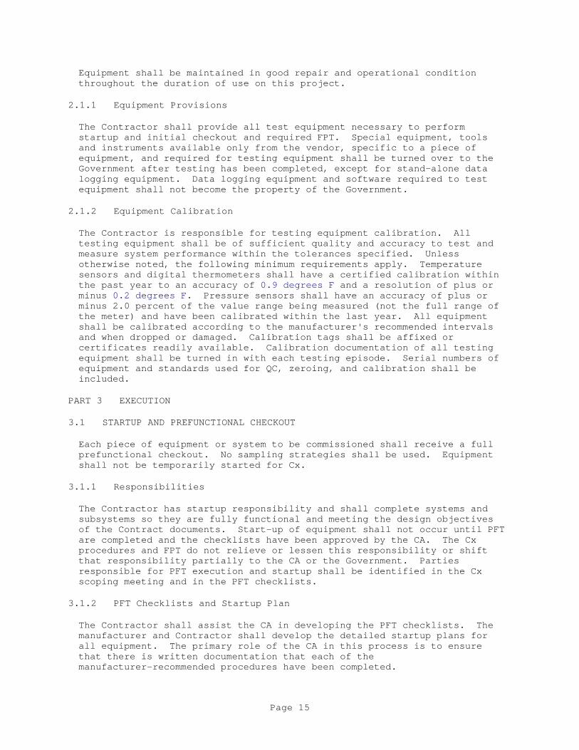
Equipment shall be maintained in good repair and operational condition throughout the duration of use on this project.
2.1.1 Equipment Provisions
The Contractor shall provide all test equipment necessary to perform startup and initial checkout and required FPT. Special equipment, tools and instruments available only from the vendor, specific to a piece of equipment, and required for testing equipment shall be turned over to the Government after testing has been completed, except for stand-alone data logging equipment. Data logging equipment and software required to test equipment shall not become the property of the Government.
2.1.2 Equipment Calibration
The Contractor is responsible for testing equipment calibration. All testing equipment shall be of sufficient quality and accuracy to test and measure system performance within the tolerances specified. Unless otherwise noted, the following minimum requirements apply. Temperature sensors and digital thermometers shall have a certified calibration within the past year to an accuracy of 0.9 degrees F and a resolution of plus or minus 0.2 degrees F. Pressure sensors shall have an accuracy of plus or minus 2.0 percent of the value range being measured (not the full range of the meter) and have been calibrated within the last year. All equipment shall be calibrated according to the manufacturer's recommended intervals and when dropped or damaged. Calibration tags shall be affixed or certificates readily available. Calibration documentation of all testing equipment shall be turned in with each testing episode. Serial numbers of equipment and standards used for QC, zeroing, and calibration shall be included.
PART 3 EXECUTION
3.1 STARTUP AND PREFUNCTIONAL CHECKOUT
Each piece of equipment or system to be commissioned shall receive a full prefunctional checkout. No sampling strategies shall be used. Equipment shall not be temporarily started for Cx.
3.1.1 Responsibilities
The Contractor has startup responsibility and shall complete systems and subsystems so they are fully functional and meeting the design objectives of the Contract documents. Start-up of equipment shall not occur until PFT are completed and the checklists have been approved by the CA. The Cx procedures and FPT do not relieve or lessen this responsibility or shift that responsibility partially to the CA or the Government. Parties responsible for PFT execution and startup shall be identified in the Cx scoping meeting and in the PFT checklists.
3.1.2 PFT Checklists and Startup Plan
The Contractor shall assist the CA in developing the PFT checklists. The manufacturer and Contractor shall develop the detailed startup plans for all equipment. The primary role of the CA in this process is to ensure that there is written documentation that each of the manufacturer-recommended procedures have been completed.
Page 15

3.1.2.1 PFT Checklists
The PFT checklists shall indicate required procedures to be executed to verify the systems are ready for start-up. The attached PFT checklists are preliminary checklists and shall be finalized by the CA 2 weeks minimum prior to PFTs being performed. The Contractor shall determine which trade is responsible for executing and documenting each of the line item tasks and note that trade on the PFT checklists. Each task may have more than one trade responsible for its execution.
3.1.2.2 Startup Plan
The Contractor shall develop the full startup plan and submit the plan to the CA for review and approval. The CA shall review and evaluate the procedures and the procedure documentation format, noting any procedures that need to be revised or added. The plan shall contain a minimum of the following:
a. The manufacturer's standard written startup procedures copied from the installation manuals with check boxes by each procedure and a summary statement with a signature block added at the end.
b. The manufacturer's field checkout sheets.
3.1.3 Execution of PFTs
Two weeks prior to PFT, the Contractor shall schedule PFT activities with the Contracting Officer and CA. The Contractor shall execute the PFTs of all equipment and systems defined in the commissioning plan. The CA may attend the PFTs. The Contractor shall fill out the PFT checklists and submit the completed checklists to the CA for review and approval.
3.1.4 Execution of Startup
Two weeks prior to startup, the Contractor shall schedule startup and checkout activities with the Contracting Officer and CA. Prior to start-up of all commissioned equipment the pre-functional checklists must be approved by the CA. The Contractor shall execute the start-up of all equipment and systems defined in the commissioning plan. The Contractor shall provide skilled technicians to execute starting of equipment and shall ensure that they are available and present during the agreed upon schedules and for sufficient duration to complete the necessary tests, adjustments, and problem-solving. The CA may attend the startup.
3.1.4.1 Startup Documentation
After startup completion, the Contractor shall provide the CA with a signed and dated copy of the completed startup checklists. Only individuals that have direct knowledge and witnessed that a line item task of the startup was actually performed shall initial or check that item off. Witnessing supervisors shall not fill out these forms.
3.1.5 Nonconformance and Approval in PFTs and Startup
The Contractor shall clearly list any outstanding items of the startup and PFT procedures that were not completed successfully at the bottom of the applicable checklist or on an attached sheet. The completed checklist and
Page 16

any outstanding deficiencies shall be provided to the Contracting Officer and the CA within 2 days of test completion. The CA shall review the report and submit either a nonconformance report or an approval form to the Contracting Officer. The Contractor shall correct all areas that are deficient or incomplete in the checklists and tests in a timely manner, and shall notify the CA as soon as outstanding items have been corrected and resubmit an updated report and a Statement of Correction on the original nonconformance report. When satisfactorily completed, the CA shall recommend approval of the execution of the PFTs and startup of each system to the Contracting Officer using a standard form. Contractor shall notify CA 2 weeks minimum prior to any re-inspection and get approval from the CA prior to starting re-inspection.
3.2 SENSOR AND ACTUATOR CALIBRATION
Contractor shall calibrate all field-installed temperature, relative humidity, CO2 and pressure sensors and gages, and actuators (dampers and valves) on all equipment. Test instruments shall have had a certified calibration within the last 12 months. Sensors installed in the unit at the factory with calibration certification provided need not be field calibrated. Procedures used shall be fully documented on the PFT checklists or other suitable forms, along with written documentation of initial, intermediate and final results.
3.2.1 Calibration Methods
Alternate methods may be used, if approved by the Government beforehand.
3.2.1.1 All Sensors
The Contractor shall verify that all sensor locations are appropriate andaway from causes of erratic operation. Verify that sensors with shieldedcables are grounded only at one end. For sensor pairs that are used todetermine a temperature or pressure difference, verify they are readingwithin 0.4 degrees F of each other for temperature and within a toleranceof each other equal to two percent of the reading for pressure. Tolerancesfor critical applications may be tighter.
3.2.1.2 Sensors Without TransmittersThe Contractor shall make a reading with a calibrated test instrument within 6 inches of the site sensor. Verify that the sensor reading (via the permanent thermostat, gage, or building automation system (BAS)) is within the tolerances listed in the table below in paragraph Tolerances, Standard Applications of the instrument-measured value. If not, install offset in BAS, calibrate, or replace sensor.
3.2.1.3 Sensors With Transmitters
The Contractor shall disconnect sensor. Connect a signal generator in place of sensor. Connect ammeter in series between transmitter and BAS control panel. Using manufacturer's resistance-temperature data, simulate minimum desired temperature. Adjust transmitter potentiometer zero until 4 mA is read by the ammeter. Repeat for the maximum temperature matching 20 mA to the potentiometer span or maximum and verify at the BAS. Record all values and recalibrate controller as necessary to conform with specified control ramps, reset schedules, proportional relationship, reset relationship, and P/I reaction. Reconnect sensor. Make a reading with a calibrated test instrument within 6 inches of the site sensor. Verify that the sensor
Page 17

reading (via the permanent thermostat, gage, or BAS) is within the tolerances listed in the table below in paragraph Tolerances, Standard Applications of the instrument-measured value. If not, replace sensor and repeat. For pressure sensors, perform a similar process with a suitable signal generator.
3.2.2 Tolerances, Standard Applications
Sensor Required Tolerance (+/-)Cooling coil, chilled and condenser water temps 0.7 FFlow rates, water 4% of designRelative humidity 4% of designAHU wet bulb or dew point 3.6 FCombustion flue temps 9.0 FHot water coil and boiler water temp 2.7 FOxygen or CO2 monitor 0.1% ptsOutside air, space air, duct air temps 0.7 FCO monitor 0.01% ptsWatt-hour, voltage & amperage 1% of designNatural gas and oil flow rate 1% of designPressures, air, water and gas 3% of designSteam flow rate 3% of designFlow rates, air 10% of designBarometric pressure 1.0 inch of Hg
3.2.3 Valve and Damper Stroke Setup and Check
3.2.3.1 EMS Readout
For all damper actuator positions checked, the Contractor shall verify the actual position against the BAS readout. Set pumps or fans to normal operating mode. Command damper closed, visually verify that damper is closed and adjust output zero signal as required. Command damper open, verify position is full open and adjust output signal as required. Command damper to three intermediate positions. If actual damper position does not reasonably correspond, replace actuator.
3.3 CONTROLS
Controls shall be tested and verified after PFT and startup and after sensor and actuator calibration, as specified in Section 23 09 23 DIRECT DIGITAL CONTROL FOR HVAC AND OTHER LOCAL BUILDNG SYSTEMS. The Contractor shall be responsible for Cx activities related to controls. Before initial startup, the Contractor shall gather and review the current control sequences and interlocks and with the CA write detailed testing procedures. All submittals indicated in Section 23 09 23 DIRECT DIGITAL CONTROL FOR HVAC AND OTHER LOCAL BUILDNG SYSTEMS shall be reviewed and approved by the CA.
3.4 TAB
**************************************************************************NOTE: For Government CA, code all GA submittals in Section 23 05 93 TESTING, ADJUSTING, AND BALANCING FOR HVAC with code "GA,CA" to indicate they go to CA for review.
**************************************************************************
Page 18

TAB shall be completed after controls are tested, checked out, and adjusted. The Contractor shall be responsible for TAB preparation and activities, as specified in Section 23 05 93 TESTING, ADJUSTING, AND BALANCING FOR HVAC. All TAB submittals indicated in Section 23 05 93 TESTING, ADJUSTING, AND BALANCING FOR HVAC shall be reviewed and approved by the CA.
3.5 LIGHTING AND LIGHTING CONTROL SYSTEMS
3.5.1 General
Commissioning of lighting and lighting control systems shall comply with commissioning procedures of the Lighting Controls Association (LCA), available online at http://www.aboutlightingcontrols.org/education. Commissioning of lighting and lighting control systems shall not begin until the building envelope is enclosed; ceiling tiles, floor coverings, and window coverings are in place; lamps have completed a minimum 100-hour burn-in period; and the furniture is in place. 100 percent% of spaces shall be commissioned.
3.5.2 Performance Parameters and Commissioning Procedures
3.5.2.1 Lighting Controls
a. Lighting control commissioning shall verify that sensor type, quantity, placement, aiming, sensitivity, and time delay match the requirements of Section 26 51 00 INTERIOR LIGHTING.
b. Sensor delays shall be set to 15 minutes in classrooms and 10 minutes elsewhere, except wall-mounted sensor switches in small non-toilet spaces shall be set for 5 minutes.
c. Controlled spaces with automatic-on/automatic off controls shall detect an entering occupant within 3 feet of doorway and within 1 second of entry.
d. Controlled spaces with manual-on/automatic off controls shall operate as indicated.
e. Controlled spaces shall be tested for walking motion to verify the LED indicator lights on sensors detect properly. Lighting may be on for this test.
f. Controlled office, classroom, and conference room spaces shall be tested for hand motion to verify the LED indicator lights on sensors detect properly. Lighting may be on for this test.
g. Controlled spaces shall be tested for 100 percent occupancy sensor coverage.
h. Testing shall verify lighting within a controlled space is not triggered on by movement in adjacent work or traffic areas.
3.5.2.2 Lighting Control Panels
a. Verify channels are programmed as indicated on the Contract Drawings.
Page 19

b. Verify channels are assigned to rooms/spaces as indicated on the Contract Drawings.
c. Verify auxiliary controls (e.g.,sensors and switches) operate as indicated on the Contract Drawings.
d. Verify auxiliary switch type, quantity, and placement.
e. Verify programming is PC-based and the software is installed and functional.
f. Verify system warns occupants prior to sweeping off.
g. Verify switch override time duration.
h. Verify programming is not lost upon power failure.
i. Verify the lighting control panel communicates with the basewide energy system via the LonWorks BAS.
3.5.2.3 Exterior Lighting Photo Sensors
a. Test the photo sensor controls for exterior lights during the daytime when conditions are such that controls should be turning off electric lighting.
b. Verify that the fixture turns off during the daytime.
c. Verify that the fixture turns on when the photo sensor is completely covered.
d. Verify that the photo sensor is in an appropriate location for the lights being controlled and is not affected by direct sunlight or obstructions in a way that causes incorrect operation.
3.5.2.4 Dimming
a. Verify dimming in spaces with removable partitions operate autonomously when partitions are in place and operate together when partitions are removed.
3.6 AIR BARRIER SYSTEM
Air barrier system quality control, performance and testing requirements are as specified in Section 01 83 16 EXTERIOR ENCLOSURE PERFORMANCE REQUIREMENTS. The Contractor shall prepare testing plans and checklists and coordinate them with CA.
3.7 FUNCTIONAL PERFORMANCE TESTING
The Contractor shall provide FPT of all commissioned equipment and systems. The CA shall direct, witness, and document the FPT of all HVAC equipment and systems and a sampling of all other equipment and systems. Sampling shall be in accordance with ASHRAE Guideline O. The Contractor shall document the FPT of all equipment and systems that are not witnessed by the CA. The Contractor shall notify the CA and the COR a minimum of 2 weeks prior to start of functional tests and shall get approval from the CA
Page 20

prior to starting functional tests. Contractor shall also provide filled out functional test readiness forms prior to functional tests for approval. Attached FPT forms are preliminary test procedure forms and will be finalized by the CA 2 weeks minimum prior to FPTs being performed. The Contractor shall execute the tests with skilled technicians provided under the direction of the CA. Systems shall be tested under all modes of operation (seasonal, occupied, unoccupied, warm-up, cool-down, full range of part- and full-load) and under abnormal modes and conditions (power failure, interlocks with other equipment, alarms, no flow, equipment failure). The Contractor shall verify that systems are run through all the building control system's sequences of operation, and components shall be verified to be responding as the sequences state. Systems shall not leak. The Contractor shall assist the CA to develop the FPT procedures in a sequential written form, and coordinate, oversee, and document the actual testing.
3.7.1 Development of Test Procedures
Before test procedures are completed, the Contractor shall provide to the CA all requested documentation regarding equipment sequence of operation and testing procedures, including procedures for equipment installed by factory representatives and a current list of change orders affecting equipment or systems. The change orders shall include an updated points list, program code, control sequences, and parameters. Using the testing parameters and requirements found in the technical sections of commissioned equipment and systems the CA shall develop specific test procedures and forms to verify and document proper operation of each piece of equipment and system. The Contractor shall assist the CA in clarifying the operation and control of commissioned equipment in areas where the specifications, control drawings, or equipment documentation is not sufficient for writing detailed testing procedures. Prior to execution, the CA shall provide the test procedures to the Contractor for review. The Contractor shall review to verify the test procedures for feasibility with installed equipment and programmed sequence of operation. The test procedure forms shall include the following, at a minimum:
a. System and equipment or component name(s) and configuration(s).b. Equipment location and ID number.c. Unique test ID number, and reference to unique PFT checklist and startup documentation ID numbers.d. Date.e. Project name.f. Participating parties.g. A copy of the section describing the test requirements.h. A copy of the specific sequence of operations or other specified parameters being verified.i. Formulas used in any calculations.j. Required pre-test field measurements.k. Instructions for setting up the test, including special cautions, alarm limits, or other equipment-specific information.l. Specific step-by-step procedures to execute the test in a clear, sequential, and repeatable format.m. Acceptance criteria of proper performance with a Yes / No check box to allow for clear marking of whether or not proper performance of each part of the test was achieved.n. A section for comments.o. Signature and date blocks for the CA, Contractor, and Contracting Officer.
Page 21

3.7.2 Test Methods
3.7.2.1 Functional Performance
FPT and verification shall be achieved by manual testing or by monitoring the performance and analyzing the results using the energy management control system's trend log capabilities or by stand-alone data loggers. A combination of methods may be required to test the complete sequence of operations. The Contractor and CA shall determine which method, or combination of methods, is most appropriate for tests that do not have a method specified. The Contractor shall provide FPT of commissioned equipment and systems. The CA or Contracting Officer's representative shall analyze any functional performance trend logs and monitoring data to verify performance, and witness and evaluate manual FPTs performed by the Contractor. The Contractor shall assist the CA in interpreting the monitoring data, as necessary.
3.7.2.2 Simulated Conditions
Simulating conditions (not by an overwritten value) shall be allowed only when timing the testing to experience actual conditions is not practical. Sensors, transducers, and devices shall have been calibrated before simulating conditions.
3.7.2.3 Overwritten Values
Overwriting sensor values to simulate a condition shall be allowed only when simulating conditions in other ways is not practical, and shall be used with caution. Sensors, transducers and devices shall have been calibrated before overwriting values.
3.7.2.4 Altering Setpoints
Altering setpoints to test a sequence is an acceptable alternative to overwriting sensor values when simulating conditions in other ways is not practical.
3.7.2.5 Indirect Indicators
Relying on indirect indicators for responses or performance shall be allowed only after visually and directly verifying and documenting, over the range of the tested parameters, that the indirect readings through the building control system represent actual conditions and responses. Much of this verification shall be completed during prefunctional testing.
3.7.2.6 Setup
Each function and test shall be performed under conditions that simulate actual conditions as close as possible. The Contractor shall provide materials, system modifications, and other necessities to produce the flows, pressures, temperatures, or other values necessary to execute the test according to the specified conditions. Where equipment requires integral safety devices to stop or prevent equipment operation unless minimum safety standards or conditions are met, FPT procedures shall demonstrate the actual performance of safety shutoffs in real or closely-simulated conditions of failure. At completion of the test, the Contractor shall return all affected building equipment and systems, due to
Page 22

these temporary modifications, to their pre-test conditions.
3.7.3 Coordination and Scheduling
FPT shall be performed after PFTs, startup, calibration, and TAB are complete for a given system. The CA shall schedule FPTs through the Contractor and Contracting Officer. Testing shall proceed from components to subsystems to systems; when the proper performance of all interacting individual systems has been achieved, the interface or coordinated responses between systems shall be checked.
3.7.4 Documentation, Review and Approval
The CA shall document the results of all FPTs witnessed by the CA (as indicated in paragraph FUNCTIONAL PERFORMANCE TESTING) using the specific test procedures and forms developed by the CA for that purpose. For all equipment and systems not witnessed by the CA, the Contractor shall document the results of all FPT and submit the completed FPT forms for CA review. The CA shall validate that the testing requirements of this Contract are accomplished, and shall note each satisfactorily demonstrated function on the test form. Formal approval of the FPT shall be made after witnessing or review by the Contracting Officer. The Contracting Officer shall give final approval on each test using the same form, and provide signed copies to the CA and the Contractor. The CA shall submit copies of the approved FPT forms with the O&M manual data and as part of the Cx Report.
3.8 NONCONFORMANCE
Every effort shall be made to expedite the testing process and minimize unnecessary delays, while not compromising the integrity of the procedures. The CA will not be pressured into overlooking deficient work or loosening acceptance criteria to satisfy scheduling or cost issues, unless there is an overriding reason to do so by direction from the Contracting Officer. Nonconformance and deficiencies observed in materials, installation, or operation shall be addressed immediately, in terms of notification to responsible parties, and providing recommended actions to correct deficiencies. The Contractor shall have responsibility for resolving construction deficiencies, and the CA shall assist with problem solving as necessary. If a design revision is deemed necessary and approved by the Contracting Officer, the designer shall have responsibility for providing design revision. The CA shall maintain a master deficiency and resolution log, and shall provide the Contracting Officer with written progress reports and test results with recommended actions.
3.8.1 Procedure
All deficiencies or nonconformance issues shall be noted and reported to the Contracting Officer and CA. The Contractor shall report in writing to the CA and Contracting Officer weekly, or at a minimum as often as Cx meetings are being scheduled, concerning the status of each apparent outstanding discrepancy identified during Cx. The report shall include explanations of any disagreements and proposals for their resolution, and a copy shall be included in the deficiency report and resolution record. Corrections of minor deficiencies may be made during the tests at the discretion of the CA, and the deficiency and resolution shall be documented on the test procedure form.
Page 23

3.8.1.1 Non-Disputed Deficiencies
When a deficiency is identified, the CA shall discuss the issue with the Contractor. When there is no dispute on the deficiency and the Contractor accepts responsibility to correct it, the CA shall document the deficiency, the adjustments or alterations required to correct it, and the Contractor's response and intentions. The next test or sequence may then be performed. After the day's work, the CA shall submit all the nonconformance reports to the Contracting Officer for signature. Copies shall be provided to the Contractor and Contracting Officer. The Contractor shall correct the Deficiency and notify the CA and COR that the equipment is ready to be retested. The CA shall reschedule the test and the test shall be repeated as specified in the paragraph Retesting.
3.8.1.2 Disputed Deficiencies
If there is a dispute about a deficiency, regarding whether it is a deficiency or who is responsible, the deficiency shall be documented on the nonconformance form with the Contractor's response and a copy given to the Contracting Officer and Contractor. Resolutions shall be made at the lowest management level possible. Additional parties shall be brought into the discussions as needed. Final interpretive and acceptance authority is with the Contracting Officer. The CA shall document the resolution process. Once the interpretation and resolution have been decided, the Contractor shall correct the deficiency, sign the statement of correction on the nonconformance form and provide it to the CA. The CA shall reschedule the test and the test shall be repeated as specified in the paragraph Retesting.
3.8.2 Retesting
The cost to retest a prefunctional test or FPT shall be solely the responsibility of the Contractor. Any required retesting by the Contractor shall not be considered a justified reason for a claim of delay or for a time extension by the Contractor. The CA or Contracting Officer's representative shall witness retesting as necessary until satisfactory performance is achieved. Notify the CA a minimum of 2 weeks prior to any retesting and get approval from the CA prior to starting any retesting.
3.8.3 Failure Due to Manufacturer Defect
If 3 or 10 percent, whichever is greater, of identical pieces of equipment (size alone does not constitute a difference) fail to perform to the Contract documents (mechanically or substantively) due to manufacturing defect, not allowing it to meet its submitted performance spec, all identical units may be considered unacceptable by the Contracting Officer. In such case, the Contractor shall provide the Contracting Officer with the following:
a. Within 1 week of notification from the Contracting Officer, the Contractor or manufacturer's representative shall examine all other identical units making a record of the findings.
b. Within 2 weeks of the original notification, the Contractor or manufacturer shall provide a signed and dated, written explanation of the problem, cause of failures, and all proposed solutions which shall include full equipment submittals. The proposed solutions shall not significantly exceed the specification requirements of the original
Page 24
installation. The Contracting Officer shall determine whether a replacement of all identical units or a repair is acceptable.
c. Two examples of the proposed solution shall be installed by the Contractor and the Contracting Officer shall be allowed to test the installations for up to 1 week, upon which the Contracting Officer will decide whether to accept the solution.
d. Upon acceptance, the Contractor and manufacturer shall replace or repair all identical items, at their expense and extend the warranty accordingly, if the original equipment warranty had begun. The replacement/repair work shall proceed with reasonable speed beginning within 1 week from when parts can be obtained.
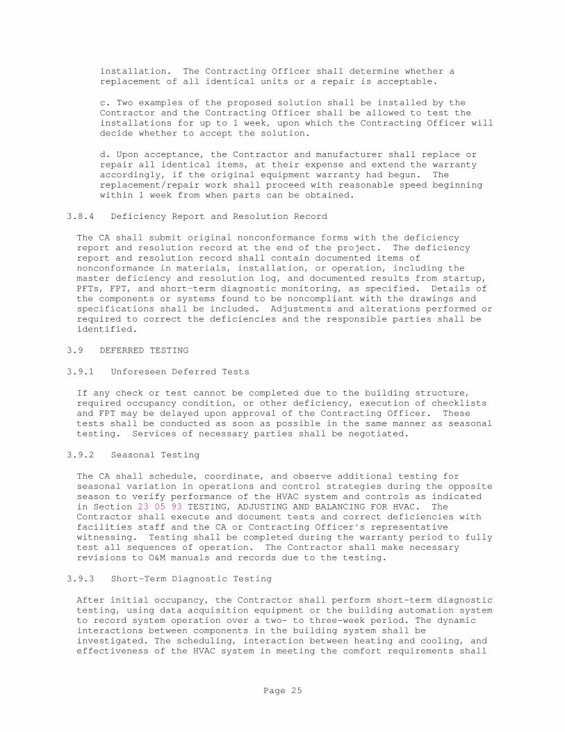
3.8.4 Deficiency Report and Resolution Record
The CA shall submit original nonconformance forms with the deficiency report and resolution record at the end of the project. The deficiency report and resolution record shall contain documented items of nonconformance in materials, installation, or operation, including the master deficiency and resolution log, and documented results from startup, PFTs, FPT, and short-term diagnostic monitoring, as specified. Details of the components or systems found to be noncompliant with the drawings and specifications shall be included. Adjustments and alterations performed or required to correct the deficiencies and the responsible parties shall be identified.
3.9 DEFERRED TESTING
3.9.1 Unforeseen Deferred Tests
If any check or test cannot be completed due to the building structure, required occupancy condition, or other deficiency, execution of checklists and FPT may be delayed upon approval of the Contracting Officer. These tests shall be conducted as soon as possible in the same manner as seasonal testing. Services of necessary parties shall be negotiated.
3.9.2 Seasonal Testing
The CA shall schedule, coordinate, and observe additional testing for seasonal variation in operations and control strategies during the opposite season to verify performance of the HVAC system and controls as indicated in Section 23 05 93 TESTING, ADJUSTING AND BALANCING FOR HVAC. The Contractor shall execute and document tests and correct deficiencies with facilities staff and the CA or Contracting Officer's representative witnessing. Testing shall be completed during the warranty period to fully test all sequences of operation. The Contractor shall make necessary revisions to O&M manuals and records due to the testing.
3.9.3 Short-Term Diagnostic Testing
After initial occupancy, the Contractor shall perform short-term diagnostic testing, using data acquisition equipment or the building automation system to record system operation over a two- to three-week period. The dynamic interactions between components in the building system shall be investigated. The scheduling, interaction between heating and cooling, and effectiveness of the HVAC system in meeting the comfort requirements shall
Page 25

be evaluated. The Contractor shall document tests and findings, and correct deficiencies according to the original testing requirements.
3.10 TRAINING
For each commissioned system, the Contractor shall conduct a training course for approximately [three][_____] building operating staff members designated by the Government in the maintenance and operation of the system, including specified hardware and software. Duration of each training course shall be in accordance with the approved training plan. The training courses shall be conducted at the project site and the Contractor shall make audiovisual recordings of all training sessions and add them to the O&M manuals. A training day is defined as 8 hours of classroom instruction, including two 15-minute breaks and excluding lunchtime, Monday through Friday, during the daytime shift in effect at the training facility. Training courses on similar commissioned systems that would be maintained by the same building operating staff members may be scheduled to occur consecutively with Government approval.
3.10.1 Training Plan and Schedule
The Contractor shall prepare the training plan which shall be reviewed by the CA and approved by the COR. Training plan shall include, for each commissioned system, an outline of the course content with proposed duration of each portion, dates, start and finish times, location(s), names and qualifications of the instructors and a list of texts and other materials that will be provided to support the training course. The training plan shall be submitted within 14 days after approval of the O&M manuals. The Contractor shall work with the CA and the COR to schedule the training activities and shall include a training schedule in the training plan.
3.10.2 Training Course Content
The training course for each commissioned system shall include, as a minimum, the following (as applicable to the system):
a. General purpose of the system (design intent)
b. Use of O&M manuals
c. Review of control drawings and schematics
d. Startup, normal operation, shutdown, unoccupied operation, seasonal changeover, manual operation, control setup and programming troubleshooting, and alarms
e. Interactions with other systems
f. Adjustments and optimizing methods for energy conservation
g. Health and safety issues
h. Special maintenance and replacement sources
i. Occupant interaction issues
Page 26

j. System response to different operating conditions
See also the individual technical specifications for commissioned systems for system-specific training content requirements. In the event of conflict between this and other sections on duration of individual training sessions, this section shall take precedence.
3.10.3 Training Documentation
Contractor shall prepare training documentation consisting of:
a. Course Sign-in Sheet: A list of course attendees which shall be signed and dated by all attendees including the instructor. Provide [two] [_____] copies of the completed sign-in sheet to the COR for archive.
b. Training Manuals: Training manuals shall include an agenda, defined objectives for each lesson, and a detailed description of the subject matter for each lesson. Where the Contractor presents portions of the course material by audiovisuals, copies of those audiovisuals shall be delivered to the Government as a part of the printed training manuals. Training manuals shall be delivered for each trainee with [two] [_____] additional copies delivered to the COR for archive.
[3.10.4 Training Verification
Contractor shall provide one copy of each completed sign-in sheet, one copy of each training manual and one copy of each videotaped course to the CA for inclusion in the Cx Report. The CA shall verify that all training in the approved training plan has been conducted.
]**************************************************************************
NOTE: The checklists provided are to be used as guides for the preparation of project checklists. Use all applicable checklists and add checklists for equipment or systems not included in this guide specification. Modify the checklists where necessary for specific project requirements. If, for example, a system needs to be tested with certain internal load, each appropriate checklist should be modified to include this requirement along with specifics on how load should be generated. All added checklists should have a level of rigor and detail commensurate with the checklists provided. Include Preliminary Commissioning Plan (including checklists) if available from Government CA. Include OPR and BOD when Contractor provides CA and they are not available to Contractor at LEED OnLine.
**************************************************************************
Page 27

APPENDIX A
PRE-FUNCTIONAL PERFORMANCE TEST CHECKLISTS
Page 28

Pre-Functional Performance Test Checklist - Multizone Air Handling Unit
For Air Handling Unit: [_____]
Checklist Item A M E T C O
Installation a. Inspection and access doors are operable and sealed. ___ ___ X ___ X ___
b. Condensate drainage is unobstructed. (Visually verify pan drains completely by pouring a cup of water into drain pan.) ___ ___ X X X ___ c. Fan belt adjusted. ___ ___ X ___ X ___
Electrical A M E T C O
a. Power available to unit disconnect. ___ X ___ X X ___
b. Power available to unit control panel. ___ X ___ X X ___ c. Proper motor rotation verified. ___ X ___ ___ X ___
d. Verify that power disconnect is located within sight of the unit it controls. ___ X ___ X X ___ [e. Power available to electric heating coil. ___ X ___ X X ___ ]
Coils A M E T C O
[a. Chilled water piping properly connected. ___ ___ X X X ___ ] [a. Refrigerant piping properly connected. ___ ___ X X X ___ ] [b. Hot water piping properly connected. ___ ___ X X X ___ ]
[b. Steam and condensate piping properly connected. ___ ___ X X X ___ ]
Controls A M E T C O
a. Control valves/actuators properly installed. ___ X X X ___ ___
b. Control valves/actuators operable. ___ X X X ___ ___
c. O/A dampers/actuators properly installed. ___ X X X ___ ___
d. O/A dampers/actuators operable. ___ X X X ___ ___
Pre-Functional Performance Test Checklist - Multizone Air Handling Unit (cont)
Page 29

A M E T C O
e. Zone dampers/actuators properly installed & dampers leak checked. ___ X X X ___ ___
f. Zone dampers/actuators operable. ___ X X X ___ ___
Testing, Adjusting, and Balancing (TAB) A M E T C O
a. Construction filters removed and replaced. ___ ___ X ___ X ___
b. TAB report approved. ___ X X ___ X
Page 30

Pre-Functional Performance Test Checklist - Variable Volume Air Handling Unit
For Air Handling Unit: [_____]
Checklist Item A M E T C O
Installation
a. Inspection and access doors are operable and sealed. ___ ___ X ___ X ___
b. Condensate drainage is unobstructed. (Visually verify drainage by pouring a cup of water into drain pan.) ___ ___ X X X ___
c. Fan belt adjusted. ___ ___ X ___ X ___
Electrical A M E T C O
a. Power available to unit disconnect. ___ X ___ X X ___
b. Power available to unit control panel. ___ X ___ X X ___
c. Proper motor rotation verified. ___ X ___ ___ X ___
d. Verify that power disconnect is located within sight of the unit it controls. ___ X ___ X X ___
[e. Power available to electric heating coil. ___ X ___ X X ___]
Coils A M E T C O
[a. Chilled water piping properly connected. ___ ___ X X X ___]
[a. Refrigerant piping properly connected. ___ ___ X X X ___]
[b. Hot water piping properly connected. ___ ___ X X X ___]
[b. Steam and condensate piping properly connected. ___ ___ X X X ___]
Page 31
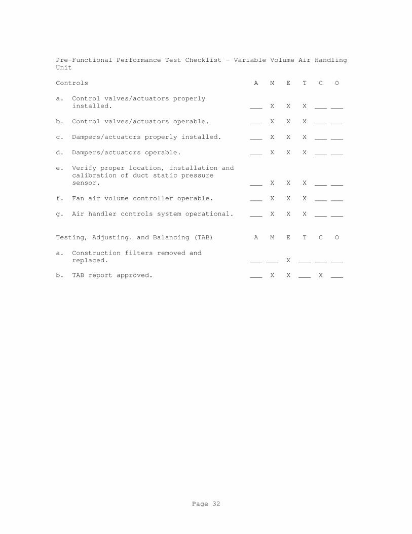
Pre-Functional Performance Test Checklist - Variable Volume Air Handling Unit
Controls A M E T C O
a. Control valves/actuators properly installed. ___ X X X ___ ___
b. Control valves/actuators operable. ___ X X X ___ ___
c. Dampers/actuators properly installed. ___ X X X ___ ___
d. Dampers/actuators operable. ___ X X X ___ ___
e. Verify proper location, installation and calibration of duct static pressure sensor. ___ X X X ___ ___
f. Fan air volume controller operable. ___ X X X ___ ___
g. Air handler controls system operational. ___ X X X ___ ___
Testing, Adjusting, and Balancing (TAB) A M E T C O
a. Construction filters removed and replaced. ___ ___ X ___ ___ ___ b. TAB report approved. ___ X X ___ X ___
Page 32

Pre-Functional Performance Test Checklist - VAV Terminal
For VAV Terminal: [_____]
Checklist Item A M E T C O Installation
[a. Reheat coil connected to hot water pipe. ___ ___ X ___ X ___]
[b. Electric reheat coil connected to local disconnect. ___ X ___ ___ X ___]
Controls A M E T C O
a. Cooling only VAV terminal controls set. ___ X X X ___ ___
b. Cooling only VAV controls verified. ___ X X X ___ ___
c. Reheat VAV terminal controls set. ___ X X X ___ ___
d. Reheat terminal/coil controls verified. ___ X X X ___ ___
Testing, Adjusting, and Balancing (TAB) A M E T C O
a. TAB report approved. ___ ___ X ___ X ___
Page 33

Pre-Functional Performance Test Checklist - DX Air Cooled Condensing Unit
For Condensing Unit: [_____]
Checklist Item A M E T C O
Installation
a. Check condenser fans for proper rotation. ___ ___ X ___ X ___
Electrical A M E T C O
a. Power available to unit disconnect. ___ X ___ X X ___
b. Power available to unit control panel. ___ X ___ X ___ ___
c. Verify that power disconnect is located within sight of the unit it controls ___ X ___ X ___ ___
Controls A M E T C O
a. Unit safety/protection devices tested. ___ ___ X X ___ ___
b. Control system and interlocks installed. ___ ___ X X ___ ___
c. Control system and interlocks operational. ___ ___ X X ___ ___
Page 34

Pre-Functional Performance Test Checklist - Pumps
For Pump: [_____]
Checklist Item A M E T C O
Installation
a. Piping system installed. ___ ___ X X X ___
Electrical A M E T C O
a. Power available to pump disconnect. ___ X ___ X X ___
b. Pump rotation verified. ___ X ___ X X ___
c. Control system interlocks functional. ___ X ___ X ___ ___
Testing, Adjusting, and Balancing (TAB) A M E T C O
a. Pressure/temperature gauges installed. ___ ___ X ___ X ___
b. TAB Report approved. ___ ___ X ___ X ___
Page 35

Pre-Functional Performance Test Checklist - Packaged Air Cooled Chiller
For Chiller: [_____]
Checklist Item A M E T C O
Installation
a. Chiller properly piped. ___ ___ X ___ ___ ___
Electrical A M E T C O
a. Power available to unit disconnect. ___ X ___ X ___ ___
b. Power available to unit control panel. ___ X ___ X ___ ___
c. Separate power is supplied to electric heating tape. ___ X ___ X ___ ___
d. Verify that power disconnect is located within sight of the unit it controls. ___ X ___ X ___ ___
Controls A M E T C O
a. Factory startup and checkout complete. ___ ___ X X ___ ___
b. Chiller safety/protection devices tested. ___ ___ X X ___ ___
c. Chilled water flow switch installed. ___ ___ X X ___ ___
d. Chilled water flow switch tested. ___ ___ X X ___ ___
e. Chilled water pump interlock installed. ___ ___ X X X ___
f. Chilled water pump interlock tested. ___ ___ ___ X
Page 36

Pre-Functional Performance Test Checklist - Centrifugal Chiller
For Chiller: [_____]
Checklist Item
Installation A M E T C O
a. Chilled water connections properly piped. ___ ___ X ___ ___ ___
b. Condenser water connections properly ___ ___ X ___ ___ ___ piped
c. Refrigerant leak detector installed. ___ ___ ___ ___ ___ ___
[d. Oxygen sensor installed and tested. ___ ___ ___ ___ ___ ___]
e. Mechanical room ventilation installed as specified. ___ ___ ___ ___ ___ ___
Electrical A M E T C O
a. Power available to unit starter. ___ X ___ X ___ ___
b. Power available to unit control panel. ___ X ___ X ___ ___
c. Verify that power disconnect is located within sight of the unit it controls. ___ X ___ X ___ ___
Controls A M E T C O
a. Factory startup and checkout complete. ___ ___ X X ___ ___
b. Chiller safety/protection devices tested. ___ ___ ___ X ___ ___
c. Chilled water flow switch installed and tested. ___ ___ X X ___ ___
e. Chilled water pump interlock installed and tested. ___ ___ ___ X ___ ___
g. Condenser water flow switch installed and tested. ___ ___ ___ X ___ ___
i. Condenser water pump interlock installed and tested. ___ ___ ___ X ___ ___
Page 37
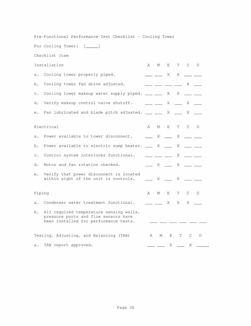
Pre-Functional Performance Test Checklist - Cooling Tower
For Cooling Tower: [_____]
Checklist Item
Installation A M E T C O
a. Cooling tower properly piped. ___ ___ X X ___ ___
b. Cooling tower fan drive adjusted. ___ ___ ___ ___ X ___
c. Cooling tower makeup water supply piped. ___ ___ X X ___ ___
d. Verify makeup control valve shutoff. ___ ___ X ___ X ___
e. Fan lubricated and blade pitch adjusted. ___ ___ X ___ X ___
Electrical A M E T C O
a. Power available to tower disconnect. ___ X ___ X ___ ___
b. Power available to electric sump heater. ___ X ___ X ___ ___
c. Control system interlocks functional. ___ ___ ___ X ___ ___
d. Motor and fan rotation checked. ___ X ___ X ___ ___
e. Verify that power disconnect is located within sight of the unit is controls. ___ X ___ X ___ ___
Piping A M E T C O
a. Condenser water treatment functional. ___ ___ X X X ___
b. All required temperature sensing wells, pressure ports and flow sensors have been installed for performance tests. ___ ___ ___ ___ ___ ___
Testing, Adjusting, and Balancing (TAB) A M E T C O
a. TAB report approved. ___ ___ X ___ X _____
Page 38

Pre-Functional Performance Test Checklist - Hot Water Boiler
For Boiler: [_____]
Checklist Item
Installation A M E T C O
a. Boiler hot water piping installed. ___ ___ X ___ ___ ___
b. Boiler makeup water piping installed. ___ ___ X ___ ___ ___
c. Boiler fuel oil piping installed. ___ ___ X X X ___
d. Boiler gas piping installed. ___ ___ X X X ___
Startup A M E T C O
a. Boiler safety/protection devices, including high temperature burner shut-off, low water cutoff, flame failure, pre- and post-purge, have been tested. ___ ___ ___ X ___ ___
b. Verify that PRV rating conforms to boiler rating. ___ ___ ___ X ___ ___
c. Boiler water treatment system functional. ___ ___ X X ___ ___
d. Boiler startup and checkout complete. ___ ___ X X ___ ___
e. Combustion efficiency demonstrated. ___ ___ X ___ X ___
Electrical A M E T C O
a. Verify that power disconnect is located within sight of the unit served. ___ X ___ X ___ ___
Controls A M E T C O
a. Hot water pump interlock installed and tested. ___ ___ ___ X ___ ___
b. Hot water proof-of-flow switch installed and tested ___ ___ X X ___ ___
c. Hot water heating controls operational. ___ ___ X X ___ ___
Testing, Adjusting, and Balancing (TAB) A M E T C O
a. TAB report approved. ___ ___ X ___ X ___
Page 39

Pre-Functional Performance Test Checklist - Steam Boiler
For Boiler: [_____]
Checklist Item
Installation A M E T C O
a. Boiler steam piping installed. ___ ___ X X X ___
b. Boiler makeup water piping installed. ___ ___ X ___ X ___
c. Boiler fuel oil piping installed. ___ ___ X X X ___
d. Boiler gas piping installed. ___ ___ X X X ___
Startup A M E T C O
a. Boiler safety/protection devices, including high temperature burner shut- off, low water cutoff, flame failure, pre and post purge, have been tested. ___ ___ ___ X ___ ___
b. Verify that PRV rating conforms to boiler rating. ___ ___ ___ X ___ ___
c. Boiler feed water system operational. ___ ___ ___ X ___ ___
d. Boiler water treatment system functional. ___ ___ X X X ___
e. Boiler startup and checkout complete. ___ ___ ___ X ___ ___
f. All steam traps operational. ___ ___ X X X ___
g. All condensate return pumps operational. ___ ___ ___ ___ X ___
h. Combustion efficiency demonstrated. ___ ___ X ___ X ___
Electrical A M E T C O
a. Verify that power disconnect is located within sight of the unit served. ___ X ___ X ___ ___
Testing, Adjusting, and Balancing (TAB) A M E T C O
a. TAB report approved. ___ ___ X ___ X ___
Page 40

Pre-Functional Performance Test Checklist - Steam/Hot Water Converter
For Converter: [_____]
Checklist Item
Installation A M E T C O
a. Converter steam piping installed. ___ ___ X ___ X ___
b. Hot water piping installed. ___ ___ X ___ ___ ___
c. Makeup water piping installed. ___ ___ X X X ___
d. Vacuum breaker installed on shell of shell and tube unit. ___ ___ X X X ___
Startup A M E T C O
a. All steam traps operational. ___ ___ X X X ___
b. All condensate return pumps operational. ___ ___ ___ X ___ ___
c. Converter safety/protection devices tested. ___ ___ X X X ___
d. Converter startup and checkout complete. ___ ___ X X X ___
Controls A M E T C O
a. Control valves/actuators properly installed. ___ ___ X ___ ___ ___
b. Control valves/actuators operable. ___ ___ X ___ ___ ___
Page 41
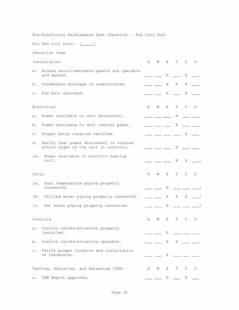
Pre-Functional Performance Test Checklist - Fan Coil Unit
For Fan Coil Unit: [_____]
Checklist Item
Installation A M E T C O
a. Access doors/removable panels are operable and sealed. ___ ___ X ___ X ___
b. Condensate drainage is unobstructed. ___ ___ X X X ___
c. Fan belt adjusted. ___ ___ X ___ X ___
Electrical A M E T C O
a. Power available to unit disconnect. ___ ___ ___ X ___ ___
b. Power available to unit control panel. ___ ___ ___ X ___ ___
c. Proper motor rotation verified. ___ ___ ___ ___ X ___
d. Verify that power disconnect is located within sight of the unit it controls. ___ ___ ___ X ___ ___
[e. Power available to electric heating coil. ___ ___ ___ X X ___]
Coils A M E T C O
[a. Dual temperature piping properly connected. ___ ___ X ___ ___ ___]
[b. Chilled water piping properly connected. ___ ___ X X X ___]
[c. Hot water piping properly connected. ___ ___ X ___ ___ ___]
Controls A M E T C O
a. Control valves/actuators properly installed. ___ ___ X ___ ___ ___
b. Control valves/actuators operable. ___ ___ X X ___ ___
c. Verify proper location and installation of thermostat. ___ ___ X ___ ___ ___
Testing, Adjusting, and Balancing (TAB) A M E T C O
a. TAB Report approved. ___ ___ X ___ X ___
Page 42

Pre-Functional Performance Test Checklist - Unit Heater
For Unit Heater: [_____]
Checklist Item
Installation A M E T C O
[a. Hot water piping properly connected. ___ ___ X ___ ___ ___]
[a. Steam and condensate piping properly connected. ___ ___ X X X ___]
Electrical A M E T C O
a. Power available to unit disconnect. ___ ___ ___ X ___ ___
b. Proper motor rotation verified. ___ ___ ___ X X ___
c. Verify that power disconnect is located within sight of the unit it controls. ___ ___ ___ X ___ ___
d. Power available to electric heating coil. ___ ___ ___ X ___ ___
Controls A M E T C O
a. Control valves properly installed. ___ ___ X ___ ___ ___
b. Control valves operable. ___ ___ X X ___ ___
c. Verify proper location and installation of thermostat. ___ ___ X ___ ___ ___
Testing, Adjusting, and Balancing (TAB) A M E T C O
a. TAB Report approved. ___ ___ X ___ X ___
Page 43
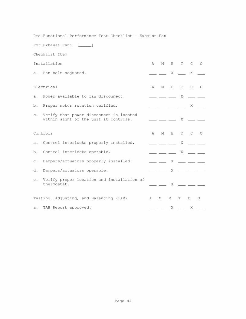
Pre-Functional Performance Test Checklist - Exhaust Fan
For Exhaust Fan: [_____]
Checklist Item
Installation A M E T C O
a. Fan belt adjusted. ___ ___ X ___ X ___
Electrical A M E T C O
a. Power available to fan disconnect. ___ ___ ___ X ___ ___
b. Proper motor rotation verified. ___ ___ ___ ___ X ___
c. Verify that power disconnect is located within sight of the unit it controls. ___ ___ ___ X ___ ___
Controls A M E T C O
a. Control interlocks properly installed. ___ ___ ___ X ___ ___
b. Control interlocks operable. ___ ___ ___ X ___ ___
c. Dampers/actuators properly installed. ___ ___ X ___ ___ ___
d. Dampers/actuators operable. ___ ___ X ___ ___ ___
e. Verify proper location and installation of thermostat. ___ ___ X ___ ___ ___
Testing, Adjusting, and Balancing (TAB) A M E T C O
a. TAB Report approved. ___ ___ X ___ X ___
Page 44

Pre-Functional Performance Test Checklist - Computer Room Unit
For Computer Room Unit: [_____]
Checklist Item
Installation A M E T C O
a. Access doors are operable and sealed. ___ ___ X ___ X ___
b. Condensate drainage is unobstructed and routed to floor drain. ___ ___ X X X ___
c. Fan belt adjusted. ___ ___ X ___ X ___
Electrical A M E T C O
a. Power available to unit disconnect. ___ X ___ X X ___
b. Proper motor rotation verified. ___ X ___ ___ X ___
c. Proper motor rotation verified. ___ X ___ ___ X ___
d. Verify that power disconnect is located within sight of the unit it controls. ___ X ___ X ___ ___
[e. Power available to reheat coils. ___ X ___ ___ X ___]
Coils/Humidifier A M E T C O
[a. Chilled water piping properly connected. ___ ___ X ___ ___ ___]
[a. Refrigerant piping properly connected. ___ ___ X X X ___]
[b. Hot water piping properly connected. ___ ___ X ___ ___ ___]
[b. Steam piping properly connected. ___ ___ X X X ___]
[c. Humidifier makeup water connected. ___ ___ X X X ___]
Controls A M E T C O
a. Control valves operable. ___ ___ X X ___ ___
b. Unit control system operable and verified. ___ ___ ___ X ___ ___
c. Verify proper location and installation of thermostat. ___ ___ X ___ ___ ___
Testing, Adjusting, and Balancing (TAB) A M E T C O
Page 45

a. TAB Report submitted. ___ ___ X ___ X ___
Page 46

Pre-Functional Performance Test Checklist - HVAC System Controls
For HVAC System: [_____]
Checklist Item
Installation A M E T C O
a. Layout of control panel matches drawings. ___ ___ X X ___ ___
b. Framed instructions mounted in or near control panel. ___ ___ X X ___ ___
c. Components properly labeled (on inside and outside of panel). ___ ___ X X ___ ___
d. Control components piped and/or wired to each labeled terminal strip. ___ ___ X X ___ ___
e. EMCS connection made to each labeled terminal strip as shown. ___ ___ X X ___ ___
f. Control wiring and tubing labeled at all terminations, splices, and junctions. ___ ___ X X ___ ___
Main Power and Control Air
a. 120 volt AC power available to panel. ___ ___ ___ X ___ ___
b. 20 psig compressed air available to panel. ___ ___ X X ___ ___
Testing, Adjusting, and Balancing (TAB) A M E T C O
a. TAB Report submitted. ___ ___ X ___ X ___
Page 47

Pre-Functional Performance Test Checklist - Single Zone Air Handling Unit
For Air Handling Unit: [_____]
Checklist Item
Installation A M E T C O
a. Inspection and access doors are operable and sealed. ___ ___ X ___ X ___
b. Condensate drainage is unobstructed. ___ ___ X X X ___
c. Fan belt adjusted. ___ ___ X ___ X ___
Electrical A M E T C O
a. Power available to unit disconnect. ___ ___ ___ X X ___
b. Power available to unit control panel. ___ ___ ___ X ___ ___
c. Proper motor rotation verified. ___ ___ ___ ___ X ___
d. Verify that power disconnect is located within sight of the unit it controls. ___ ___ ___ X ___ ___
e. Power available to electric heating coil. ___ ___ ___ X ___ ___
Coils A M E T C O
[a. Chilled water piping properly connected. ___ ___ X ___ ___ ___]
[a. Refrigerant piping properly connected. ___ ___ X X X ___]
[c. Hot water piping properly connected. ___ ___ X ___ ___ ___]
[c. Steam and condensate piping properly connected. ___ ___ X X X ___]
Controls A M E T C O
a. Control valves/actuators properly installed. ___ ___ X ___ ___ ___
b. Control valves/actuators operable. ___ ___ X ___ ___ ___
c. Dampers/actuators properly installed. ___ ___ X ___ ___ ___
d. Dampers/actuators operable. ___ ___ X ___ ___ ___
e. Verify proper location and installation of thermostat. ___ ___ X ___ ___ ___
Page 48

Testing, Adjusting, and Balancing (TAB) A M E T C O
a. TAB Report approved. ___ ___ X ___ X ___
Page 49

Pre-Functional Performance Test Checklist - Energy Recovery System
For Energy Recovery System: [_____]
Checklist Item
Installation A M E T C O
a. Recovery system piping installed. ___ ___ X ___ X ___
Startup A M E T C O
a. Startup and checkout complete. ___ ___ X X X ___
Controls A M E T C O
a. Control valves/actuators properly installed. ___ ___ X ___ ___ ___
b. Control valves/actuators operable. ___ ___ X ___ ___ ___
Page 50

- End of Appendix A -
Page 51

APPENDIX B
FUNCTIONAL PERFORMANCE TESTS CHECKLISTS
Page 52

Functional Performance Test - Pump [_____]
NOTE: Prior to performing this test, for closed loop systems ensure that the system is pressurized and the make-up water system is operational, or for open loop systems ensure that the sumps are filled to the proper level.
1. Activate pump start using control system commands.
a. Verify correct operation in:
HAND__________ OFF__________ AUTO__________
b. Verify pressure drop across strainer:
Strainer inlet pressure __________ psig
Strainer outlet pressure _________ psig
c. Verify pump inlet/outlet pressure reading, compare to Testing, Adjusting, and Balancing (TAB) Report and pump design conditions.
DESIGN TAB ACTUAL
Pump inlet pressure psig _________ __________ __________
Pump outlet pressure psig _________ __________ __________
d. Operate pump at shutoff and at 100 percent of designed flow when all components are in full flow. Plot test readings on pump curve and compare results against readings taken from flow measuring devices.
SHUTOFF 100 percent
Pump inlet pressure psig __________ __________
Pump outlet pressure psig __________ __________
Pump flow rate gpm __________ __________
SETPOINTDifferential Pressure Transmitter ________
Page 53

Functional Performance Test (cont) - Pump [_____]
e. For variable speed pumps, operate pump at shutoff (shutoff to be done in manual on variable speed drive at the minimum rpm that the system is being controlled at) and at minimum flow or when all components are in full by-pass. Plot test readings on pump curve and compare results against readings taken from flow measuring devices.
SHUTOFF 100 percent Pump inlet pressure psig __________ __________
Pump outlet pressure psig __________ __________
Pump flow rate gpm __________ __________
SETPOINT Differential Pressure Transmitter ________
2. Measure motor amperage each phase and voltage phase to phase and phase to ground for both the full flow and the minimum flow conditions. Compare amperage to nameplate FLA
a. Full flow:
Nameplate FLA __________
Amperage Phase 1 __________ Phase 2 __________ Phase 3 __________
Voltage Ph1-Ph2 __________ Ph1-Ph3 __________ Ph2-Ph3 __________ Voltage Ph1-gnd __________ Ph2-gnd __________ Ph3-gnd __________
b. Minimum flow:
Amperage Phase 1 __________ Phase 2 __________ Phase 3 __________
Voltage Ph1-Ph2 __________ Ph1-Ph3 __________ Ph2-Ph3 __________ Voltage Ph1-gnd __________ Ph2-gnd __________ Ph3-gnd __________
3. Note unusual vibration, noise, etc.
___________________________________________________________________________
___________________________________________________________________________
Page 54

Functional Performance Test (cont) - Pump [_____]
4. Certification: We the undersigned have witnessed the above functional performance tests and certify that the item tested has met the performance requirements in this section of the specifications.
Signature and Date
Contractor's Commissioning Specialist _____________________________
Contractor's Mechanical Representative _____________________________
Contractor's Electrical Representative _____________________________
Contractor's TAB Representative _____________________________
Contractor's Controls Representative _____________________________
Contracting Officer's Representative _____________________________
Design Agency Representative _____________________________
Using Agency's Representative _____________________________
Page 55

Functional Performance Test - Centrifugal Chiller [_____]
Note: If water-cooled chiller perform in conjunction with Cooling Tower test.
1. Demonstrate operation of chilled water system in accordance with specifications including the following: Start building air handler to provide load for chiller. Activate controls system chiller start sequence as follows:
a. Time of day startup program initiates chiller start: ____________
b. Record outdoor air temperature: ____________
c. Start condenser water pump and establish condenser water flow. Verify chiller condenser water proof-of-flow switch operation._____
d. Start chilled water pump and establish chilled water flow. Verify chiller chilled water proof-of-flow switch operation. ____________
e. Verify control system energizes chiller start sequence.__________
f. Verify chiller senses chilled water temperature above set point and control system activates chiller start. _________________________
g. Verify functioning of "soft start" sequence. __________________
h. Record data in 2, 3 and 4 below on fully load chiller.
i. Shut off air handling equipment to remove load on chilled water system. Verify chiller shutdown sequence is initiated and accomplished after load is removed. _____________________________
j. Restart air-handling equipment one minute after chiller shut down. Verify condenser water pump, cooling tower, and chiller restart sequence. _________________________________________________________
2. Verify chiller inlet/outlet pressure and flow reading, compare to Testing, Adjusting, and Balancing (TAB) Report, chiller design conditions, and chiller manufacturer's performance data.
DESIGN TAB REPORT ACTUAL
Chiller inlet pressure psig __________ __________ ________
Chiller outlet pressure psig __________ __________ ________
Chiller flow GPM __________ __________ ________
3. Measure chiller amperage each phase and voltage phase to phase and phase to ground for both the fully loaded condition. Motor F/L AMPS Amperage Phase 1 __________ Phase 2 __________ Phase 3 _______
Page 56

Voltage Ph1-Ph2 __________ Ph1-Ph3 __________ Ph2-Ph3 _______
Voltage Ph1-gnd __________ Ph2-gnd __________ Ph3-gnd _______
Page 57

Functional Performance Test (cont) - Centrifugal Chiller [_____]
4. a. Record the following information: Design
Outdoor air temperature ________________ deg F Ambient dry bulb temperature ___________ deg F __________ Entering chilled water temperature _____ deg F __________ Leaving chilled water temperature ______ deg F __________
b. Calculate chiller load at ambient conditions and compare to chiller rated capacity from manufacturer's literature. Calculated ________ Ton Rated ________ Ton.
5. Unusual vibration, noise, etc. _______________________________________________________________________
_______________________________________________________________________
6. Certification: We the undersigned have witnessed the above functional performance tests and certify that the item tested has met the performance requirements in this section of the specifications.
Signature and Date
Contractor's Commissioning Specialist _____________________________
Contractor's Mechanical Representative _____________________________
Contractor's Electrical Representative _____________________________
Contractor's TAB Representative _____________________________
Contractor's Controls Representative _____________________________
Contracting Officer's Representative _____________________________
Design Agency Representative _____________________________
Using Agency's Representative _____________________________
Page 58

Functional Performance Test - Cooling Tower [_____]
1. Demonstrate operation of the cooling tower in accordance with specification and the following:
a. Activate cooling tower fan start using control system command. This should first start condenser water pump, establish flow, delay fan start, as specified, to equalize flow in distribution basin and sump. Verify fan start after timed delay._____________________________________
b. After chiller startup, control system should modulate bypass valve and two-speed fan motor to maintain condenser water set point. Verify function of bypass valve under varying loads. __________________
c. Verify cooling tower interlock with chiller._____________________
d. Verify makeup water float valve is functioning. ___________________
e. Activate chemical treatment feed valve, verify makeup of chemical treatment system, pump, and controls.______________________________
f. Record the following:
Entering water temperature _____ deg F Leaving water temperature: _____ deg F Measured water flow: _____ gpm Entering air wet bulb temperature: _____ deg F
2. Compare results with test results from cooling tower specification test.
3. a. Stop all building cooling equipment so that cooling tower pumps stop. Observe tower for at least 15 minutes and verify no overflow occurs ___________. b. Start cooling tower pumps in hand and observe pumps for air binding/cavitation , none allowed __________.
4.Certification: We the undersigned have witnessed the above functional performance tests and certify that the item tested has met the performance requirements in this section of the specifications. Signature and Date
Contractor's Commissioning Specialist _____________________________
Contractor's Mechanical Representative _____________________________
Contractor's Electrical Representative _____________________________
Contractor's TAB Representative _____________________________
Contractor's Controls Representative _____________________________
Contracting Officer's Representative _____________________________
Design Agency Representative _____________________________
Page 59
Using Agency's Representative _____________________________
Page 60

Functional Performance Test Checklist - VAV Terminals
The Contracting officer will select VAV terminals to be spot-checked during the functional performance test. The number of terminals selected shall not exceed 10 percent.
1. Functional Performance Test: Contractor shall demonstrate operation of selected VAV boxes in accordance with specifications including the following:
a. Cooling only VAV boxes:
(1) Verify VAV box response to room temperature set point adjustment. Turn thermostat to 5 degrees F below ambient and measure maximum airflow. Turn thermostat to 5 degrees F above ambient and measure minimum airflow. Setting Measured Design Maximum flow [______] [_____] [_____] cfm Minimum flow [______] [_____] [_____] cfm
b. Cooling with reheat VAV boxes:
(1) Verify VAV box response to room temperature set point adjustment. Turn thermostat to 5 degrees F above ambient and measure maximum airflow. Turn thermostat to 5 degrees F below ambient and measure minimum airflow.
Setting Measured Design Maximum flow [______] [_____] [_____] cfm Minimum flow [______] [_____] [_____] cfm
(2) Verify reheat coil operation range (full closed to full open) by turning room thermostat 5 degrees F above ambient _______.
With heating water system and boiler in operation providing design supply hot water temperature record the following:
Design HW supply temperature______ deg F Actual HW supply temperature______ deg F AHU supply air temperature______ deg F VAV supply air temperature______ deg F Calculate coil capacity and compare to design: Design ______ BTU/hr Actual _____BTU/hr
Page 61

Functional Performance Test Checklist (cont)- VAV Terminals
c. Parallel Fan powered VAV boxes:
(1) Verify VAV box responses to call for heating via set point adjustment. Change from cooling set point to heating set point. Verify cooling damper closes to minimum position, blower fan energizes according to sequence of operation, and upon further drop in space temperature, heating coil activation. __________
With heating water system in operation providing design supply hot water temperature record the following:
Design HW supply temperature______ deg F Actual HW supply temperature______ deg F AHU supply air temperature______ deg F VAV supply air temperature______ deg F Calculate coil capacity and compare to design: Design ______ BTU/hr Actual _____BTU/hr
(2) Check primary air damper maximum/minimum flow settings and compare to actual measured flows.
Setting Measured Design Maximum flow [______] [_____] [_____] cfm Minimum flow [______] [_____] [_____] cfm
(3) Check blower fan flow. [_____] cfm
(4) Verify free operation of fan backdraft damper (insure no primary air is being discharged into plenum space). _____________________________________________________________________________
d. Series Fan Powered VAV boxes
(1) Ensure VAV fan starts prior to AHU fan
(2) Verify VAV box response to sensor call for heating via set point adjustment. Change from cooling set point to heating set point. Verify cooling damper closes to minimum position and upon further drop in space temperature, heating coil activation. With heating water system and boiler in operation providing design supply hot water temperature record the following:
Design HW supply temperature______ deg F Actual HW supply temperature______ deg F AHU supply air temperature______ deg F VAV supply air temperature______ deg F Calculate coil capacity and compare to design: Design ______ BTU/hr Actual _____BTU/hr
(3) Check primary air damper maximum/minimum flow settings and compare to actual measured flows.
Page 62

Setting Measured Design Maximum flow [______] [_____] [_____] cfm Minimum flow [______] [_____] [_____] cfm
Page 63

Functional Performance Test Checklist (cont)- VAV Terminals
(4) Verify that minimal primary air is discharging into the plenum space when in full cooling mode.
(5) Verify that no plenum air is being induced from the plenum space into the supply air during full cooling by measuring supply air temperature and comparing to primary air temperature
Primary air temp _____ deg F Supply air temp _____ deg F
2. Certification: We the undersigned have witnessed the above functional performance tests and certify that the item tested has met the performance requirements in this section of the specifications.
Signature and Date Contractor's Commissioning Specialist ___________________________ Contractor's Mechanical Representative _____________________________
Contractor's Electrical Representative _____________________________
Contractor's TAB Representative _____________________________ Contractor's Controls Representative _____________________________
Contracting Officer's Representative _____________________________
Design Agency Representative _____________________________
Using Agency's Representative _____________________________
Page 64

Functional Performance Test Checklist - Variable Volume Air Handling Unit
For Air Handling Unit: [_____]
1. Functional Performance Test: Contractor shall verify operation of air handling unit in accordance with specification including the following:
a. Ensure that a slight negative pressure exists on inboard side of the outside air dampers throughout the operation of the dampers. Modulate OA, RA, and EA dampers from fully open to fully closed positions__________.
b. The following shall be verified [supply fan operating][supply and return fans operating] mode is initiated:
(1) All dampers in normal position prior to fan start___________.
(2) All valves in normal position prior to fan start____________.
(3) System safeties allow start if safety conditions are met.____
(4) VAV fan controller shall "soft-start" fan. __________________
(5) Modulate all VAV boxes to minimum air flow and verify that the static pressure does not exceed the high static pressure shutdown setpoint_____________.
(6) Return all VAV boxes to auto _______________.
c. Occupied mode of operation - economizer de-energized.
(1) Outside air damper at minimum position. _____________________
(2) Return air damper open. _____________________________________
(3) Relief air damper [at minimum position] [closed]. ___________
(4) Chilled water control valve modulating to maintain leaving air temperature set point. Setpoint _______deg F Actual _____deg F
(5) Fan VAV controller receiving signal from duct static pressure sensor and modulating fan to maintain supply duct static pressure set point. Setpoint _______inches-wg Actual _____inches-wg
d. Occupied mode of operation - economizer energized.
(1) Outside air damper modulated to maintain mixed air temperature set point. Setpoint _______deg F, Actual _____deg F, Outside air damper position ________%.
(2) Relief air damper modulates with outside air damper according to sequence of operation. Relief air damper position_____________%.
(3) Chilled water control valve modulating to maintain leaving
Page 65
air temperature set point. Setpoint _______deg F Actual _____deg F
(4) Hot water control valve modulating to maintain leaving air temperature set point. Setpoint _______deg F Actual _____deg F
Page 66

Functional Performance Test Checklist (cont) - Variable Volume Air Handling Unit
(5) Fan VAV controller receives signal from duct static pressure sensor and modulates fan to maintain supply duct static pressure set point. Setpoint inches-wg________________ Actual inches-wg___________
e. Unoccupied mode of operation
(1) Observe fan starts when space temperature calls for heating and/or cooling. _________ Note: This does not apply to series boxes. (2) All dampers in normal position. _____________________________(3) Verify space temperature is maintained as specified in sequence of operation. _______________
f. The following shall be verified when the [supply fan off][supply and return fans off] mode is initiated:
(1) All dampers in normal position. _____________________________
(2) All valves in normal position. ______________________________
(3) Fan de-energizes. ___________________________________________
g. Verify the chilled water coil control valve operation by setting all VAV's to maximum and minimum cooling.
Max Cooling Supply air temp. _____ deg F Verify cooling valve operation_______.
Min cooling
Supply air temp. _____ deg F Verify cooling valve operation_______.
h. Verify safety shut down initiated by low temperature protection thermostat. _________
i. Verify occupancy schedule is programmed into time clock/UMCS________.
2. Certification: We the undersigned have witnessed the above functional performance tests and certify that the item tested has met the performance requirements in this section of the specifications. Signature and Date
Contractor's Commissioning Specialist _____________________________
Contractor's Mechanical Representative _____________________________
Contractor's Electrical Representative _____________________________
Contractor's TAB Representative _____________________________
Contractor's Controls Representative _____________________________
Page 67

Design Agency Representative _____________________________
Contracting Officer's Representative _____________________________
Using Agency's Representative _____________________________
Page 68

Functional Performance Test Checklist - Single Zone Air Handling Unit
For Air Handling Unit: [_____]
1. Functional Performance Test: Contractor shall verify operation of air handling unit in accordance with specification including the following:
a. Ensure that a slight negative pressure exists on inboard side of the outside air dampers throughout the operation of the dampers. Modulate OA, RA, and EA dampers from fully open to fully closed positions.
a. The following shall be verified when the [supply fan operating] [supply and return fans operating] mode is initiated:
(1) All dampers in normal position prior to fan start___________.
(2) All valves in normal position prior to fan start____________.
(3) System safeties allow start if safety conditions are met. ___
b. Occupied mode of operation - economizer de-energized.
(1) Outside air damper at minimum position.______________________
(2) Return air damper open.______________________________________
(3) Relief air damper [at minimum position][closed].____________
(4) Chilled water control valve modulating to maintain space cooling temperature set point. Setpoint _______deg F Actual _____deg F
(5) Hot water control valve modulating to maintain space heating temperature set point input from outside air temperature controller. ______
c. Occupied mode of operation - economizer energized.
(1) Outside air damper modulated to maintain mixed air temperature set point. Setpoint _______deg F Actual _____deg F O/A damper position ___________% Return Air Temperature_____deg F Outside Air Temperature _______ deg F
(2) Relief air damper modulates with outside air damper according to sequence of operation. Relief air damper position ________%
(3) Chilled water control valve modulating to maintain space cooling temperature set point. Setpoint _______deg F Actual _____deg F Return sensor overrides to normal operation.
d. Unoccupied mode of operation. (1) Observe fan starts when space temperature calls for heating/cooling ____. (2) All dampers in normal position. _________________________ (3) Verify low limit space temperature is maintained as specified in sequence of operation. ______________________________________
Page 69

Functional Performance Test Checklist (cont) - Single Zone Air Handling Unit
e. The following shall be verified when the [supply fan off][supply and return fans off] mode is initiated:
(1) All dampers in normal position.______________________________
(2) All valves in normal position._______________________________
(3) Fan de-energizes. ___________________________________________
f. Verify cooling coil and heating coil operation by varying thermostat set point from cooling set point to heating set point and returning to cooling set point________.
g. Verify safety shut down initiated by low temperature protection thermostat________.
h. Verify occupancy schedule is programmed into time clock/UMCS________.
2. Certification: We the undersigned have witnessed the above functional performance tests and certify that the item tested has met the performance requirements in this section of the specifications.
Signature and Date
Contractor's Commissioning Specialist ____________________________ Contractor's Mechanical Representative _____________________________
Contractor's Electrical Representative _____________________________
Contractor's TAB Representative _____________________________
Contractor's Controls Representative _____________________________
Design Agency Representative _____________________________
Contracting Officer's Representative _____________________________
Using Agency's Representative _____________________________
Page 70

Functional Performance Test Checklist - Multi-zone Air Handling Unit
For Air Handling Unit: [_____]
1. Functional Performance Test: Contractor shall verify operation of air handling unit in accordance with specification including the following:
a. Ensure that a slight negative pressure exists on inboard side of the outside air dampers throughout the operation of the dampers. Modulate OA, RA, and EA dampers from fully open to fully closed positions.
b. The following shall be verified when the supply and return fans operating mode is initiated:
(1) All dampers in normal position. _____________________________
(2) All valves in normal position. ______________________________
(3) System safeties allow start if safety conditions are met. ___
b. Occupied mode of operation - economizer de-energized.
(1) Outside air damper at minimum position. _____________________
(2) Return air damper open. _____________________________________
(3) Relief air damper [at minimum position] [closed]. ___________
(4) Chilled water control valve modulating to maintain cold deck supply air temperature set point. Setpoint ______deg F Actual _____deg F
(5) Hot water control valve modulating to maintain hot deck supply air temperature set point input from outside air temperature controller. Setpoint _______deg F Actual _____deg F O/A ________deg F
c. Occupied mode of operation - economizer energized. Note outside air and return air temperature sensors may need to be simulated.
(1) Outside air damper modulates to maintain mixed air temperature set point. Setpoint _______deg F Actual _____deg F Return Air Temperature _______deg F Outside Air Temperature _______deg F
(2) Relief air damper modulates with outside air damper according to sequence of operation.__________________________________________________
(3)Chilled water control valve modulating to maintain cold deck supply air temperature set point. Setpoint ______deg F Actual _____deg F (4)Hot water control valve modulating to maintain hot deck supply air temperature set point input from outside air temperature controller. Setpoint _______deg F Actual _____deg F O/A ______ deg FReturn temperature sensors to normal operation.
Page 71

Functional Performance Test Checklist (cont) - Multi-zone Air Handling Unit
d. Unoccupied mode of operation note time clock and space temperature sensor may require simulation.(4) Observe fan starts when space temperature calls for heating/cooling. (5) All dampers in normal position. ___________________________(6) Verify low limit space temperature is maintained as specified in sequence of operation. _____________________________________
e. The following shall be verified when the supply and return fans off mode is initiated:
(1) All dampers in normal position. ____________________________
(2) All valves in normal position. _____________________________
(3) Fan de-energizes. __________________________________________Note: return time clock and space temperature sensors to normal operation.
f. Verify zone damper operation by varying zone thermostat set points from cooling set point to heating set point and returning to cooling set point. ________________________________________________________________
g. Verify safety shut down initiated by low temperature protection thermostat. _____________________________________________________________
h. Index room thermostats to full cooling then to full heating. Measure and record cold deck, hot deck, and supply air temperatures and determine damper leakage for a minimum of 2 zones.
Cold deck temperature __________ degrees FHot deck temperature __________ degrees F
Zone _______Zone ____ Supply Air Temperature at Max Cooling _______deg FZone ____ Supply Air Temperature at Max Heating _______deg FZone ____Hot Deck Damper leakage at Max cooling _______CFMZone ____Cold Deck Damper leakage at Max heating _______CFM
Zone _______Zone ____ Supply Air Temperature at Max Cooling _______deg FZone ____ Supply Air Temperature at Max Heating _______deg FZone ____Hot Deck Damper leakage at Max cooling _______CFMZone ____Cold Deck Damper leakage at Max heating _______CFM
i. Verify occupancy schedule is programmed into time clock/UMCS________.
Page 72

Functional Performance Test Checklist (cont) - Multi-zone Air Handling Unit
2. Certification: We the undersigned have witnessed the above functional performance tests and certify that the item tested has met the performance requirements in this section of the specifications.
Signature and Date
Contractor's Commissioning Specialist _____________________________
Contractor's Mechanical Representative _____________________________
Contractor's Electrical Representative _____________________________
Contractor's TAB Representative _____________________________
Contractor's Controls Representative _____________________________
Design Agency Representative _____________________________
Contracting Officer's Representative _____________________________
Using Agency's Representative _____________________________
Page 73

Functional Performance Test Checklist - Packaged Air Cooled Chiller
For Chiller: [_____]
1. Functional Performance Test: Contractor shall demonstrate operation of chilled water system in accordance with specifications including the following: Start building air handler to provide load for chiller. Activate controls system chiller start sequence as follows.
a. Start chilled water pump and establish chilled water flow. Verify chiller-chilled water proof-of-flow switch operation. ____________Record outdoor air temperature. ____________
b. Verify control system energizes chiller start sequence. ________
c. Verify chiller senses chilled water temperature above set point and control system activates chiller start. Setpoint_____deg F Actual_____ deg F
d. Verify functioning of "soft start" sequence. ___________________ e. Verify and record chiller data in accordance with 2, 3 and 4 below on fully loaded chiller.
f. Shut off air handling equipment to remove load on chilled water system. Verify chiller shutdown sequence is initiated and accomplished after load is removed. ___________________________________________
g. Restart air handling equipment one minute after chiller shut down. Verify chiller restart sequence. ________________________________
2. Verify chiller inlet/outlet pressure reading, compare to Testing, Adjusting, and Balancing (TAB) Report, chiller design conditions, and chiller manufacturer's performance data.
DESIGN TAB TEST ACTUAL
Chiller inlet pressure (psig) __________ __________ __________
Chiller outlet pressure (psig) __________ __________ __________
Chiller flow GPM __________ __________ __________
3. Verify chiller amperage each phase and voltage phase-to-phase and phase-to-ground. Motor F/L AMPS Amperage Phase 1 __________ Phase 2__________ Phase 3_______ _____
Voltage Ph1-Ph2 __________ Ph1-Ph3__________ Ph2-Ph3_______ Voltage Ph1-gnd __________ Ph2-gnd__________ Ph3-gnd_______
Page 74

Functional Performance Test Checklist (cont) - Packaged Air Cooled Chiller
4. a. Record the following information:
DesignOutdoor air temperature ________________ degrees F Ambient dry bulb temperature ___________ degrees F _____degrees FEntering chilled water temperature _____ degrees F _____degrees FLeaving chilled water temperature ______ degrees F _____degrees F
b. Calculate chiller load at ambient conditions and compare to chiller rated capacity from manufacturer's literature. Calculated ________ Ton Rated ________ Ton.
5. Unusual vibration, noise, etc. ___________________________________________________________________________
___________________________________________________________________________
6. Certification: We the undersigned have witnessed the above functional performance tests and certify that the item tested has met the performance requirements in this section of the specifications.
Signature and Date
Contractor's Commissioning Specialist _____________________________
Contractor's Mechanical Representative _____________________________
Contractor's Electrical Representative _____________________________
Contractor's TAB Representative _____________________________
Contractor's Controls Representative _____________________________
Design Agency Representative _____________________________
Contracting Officer's Representative _____________________________
Using Agency's Representative _____________________________
Page 75

Functional Performance Test Checklist - Air Cooled Condensing Unit
For Condensing Unit: [_____]
1. Functional Performance Test: Contractor shall demonstrate operation of refrigeration system in accordance with specifications including the following: Start building air handler to provide load for condensing unit. Activate controls system start sequence as follows.
a. Start air handling unit. Verify control system energizes condensing unit start sequence. __________________________________________
b. Verify and record data in 2 and 3 below. c. Shut off air handling equipment to verify condensing unit de-energizes. ___________________________________________________________
d. Restart air handling equipment one minute after condensing unit shut down. Verify condensing unit restart sequence. _____________________
2. Verify condensing unit amperage each phase and voltage phase to phase and phase to ground. Motor Full-Load Amps __________ Amperage Phase 1 __________ Phase 2__________ Phase 3_______
Voltage Ph1-Ph2 __________ Ph1-Ph3__________ Ph2-Ph3_______ Voltage Ph1-gnd __________ Ph2-gnd__________ Ph3-gnd_______
3. Record the following information: Ambient dry bulb temperature __________ degrees F Suction pressure __________ psig Discharge pressure __________ psig 4. Unusual vibration, noise, etc. ___________________________________________________________________________
___________________________________________________________________________
5. Certification: We the undersigned have witnessed the above functional performance tests and certify that the item tested has met the performance requirements in this section of the specifications. Signature and DateContractor's Commissioning Specialist _____________________________
Contractor's Mechanical Representative _____________________________
Contractor's Electrical Representative _____________________________
Contractor's TAB Representative _____________________________
Contractor's Controls Representative _____________________________
Design Agency Representative _____________________________
Page 76

Contracting Officer's Representative _____________________________
Using Agency's Representative _____________________________
Page 77

Functional Performance Test Checklist - Hot Water Boiler
For Boiler: [_____]
1. Functional Performance Test: Contractor shall demonstrate operation of hot water system in accordance with specifications including the following: Start building heating equipment to provide load for boiler. Activate controls system boiler start sequence as follows.
a. Start hot water pump and establish hot water flow. Verify boiler hot water proof-of-flow switch operation. ____________________________Record outdoor air temperature. ____________________________
b. Verify control system energizes boiler start sequence. _________
c. Verify boiler senses hot water temperature below set point and control system activates boiler start. Setpoint_________deg F
2. Verify boiler inlet/outlet pressure reading, compare to Test and Balance (TAB) Report, boiler design conditions, and boiler manufacturer's performance data.
DESIGN SYSTEM TEST ACTUALBoiler inlet water temperature deg F __________ _________ _________Boiler outlet water temperature deg F __________ _________ _________Boiler outlet pressure psig __________ _________ _________Boiler flow rate gpm __________ _________ _________Flue-gas temperature at boiler outlet deg F _________ _________Percent carbon dioxide in flue-gas _________ _________Draft at boiler flue-gas exit inches-wg _________ _________Stack emission pollutants concentration __________ _________ _________Fuel type __________ _________ _________Combustion efficiency __________ _________ _________
3. Record the following information:
Ambient dry bulb temperature to determine reset schedule_____degrees FBuilding Entering hot water temperature _____degrees FBuilding Leaving hot water temperature ____ degrees F
4. Verify temperatures in item 3 are in accordance with the reset schedule. ______________________________________________________________
5. Verify proper operation of boiler safeties. ________________________ a. Low water_____ b. Water flow____ c. Flame failure____ d. Pilot failure____ e. Pre and Post Purge failure____ f. Pressure relief___ g. High temperature____
6. Shut off building heating equipment to remove load on hot water system. Verify boiler shutdown sequence is initiated and accomplished after
Page 78

load is removed. _______________________________________________________
Page 79

Functional Performance Test Checklist (cont) - Hot Water Boiler
7. Unusual vibration, noise, etc.
___________________________________________________________________________
___________________________________________________________________________
8. Certification: We the undersigned have witnessed the above functional performance tests and certify that the item tested has met the performance requirements in this section of the specifications.
Signature and Date
Contractor's Commissioning Specialist _____________________________
Contractor's Mechanical Representative _____________________________
Contractor's Electrical Representative _____________________________
Contractor's TAB Representative _____________________________
Contractor's Controls Representative _____________________________
Design Agency Representative _____________________________
Contracting Officer's Representative _____________________________
Using Agency's Representative _____________________________
Page 80
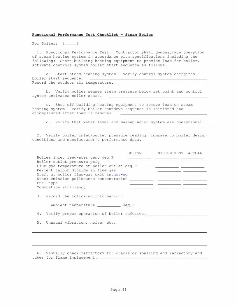
Functional Performance Test Checklist - Steam Boiler
For Boiler: [_____]
1. Functional Performance Test: Contractor shall demonstrate operation of steam heating system in accordance with specifications including the following: Start building heating equipment to provide load for boiler. Activate controls system boiler start sequence as follows.
a. Start steam heating system. Verify control system energizes boiler start sequence. __________________________________________________Record the outdoor air temperature. ______________________________________
b. Verify boiler senses steam pressure below set point and control system activates boiler start. __________________________________________
c. Shut off building heating equipment to remove load on steam heating system. Verify boiler shutdown sequence is initiated and accomplished after load is removed. _____________________________________
d. Verify that water level and makeup water system are operational. _____________________________________________________________________________
2. Verify boiler inlet/outlet pressure reading, compare to boiler design conditions and manufacturer's performance data.
DESIGN SYSTEM TEST ACTUAL Boiler inlet feedwater temp deg F __________ __________ __________ Boiler outlet pressure psig __________ __________ __________ Flue-gas temperature at boiler outlet deg F __________ __________ Percent carbon dioxide in flue-gas __________ __________ Draft at boiler flue-gas exit inches-wg __________ __________ Stack emission pollutants concentration __________ __________ __________ Fuel type __________ __________ __________ Combustion efficiency __________ __________ __________
3. Record the following information:
Ambient temperature __________ deg F 4. Verify proper operation of boiler safeties.__________________________
5. Unusual vibration, noise, etc. ___________________________________________________________________________
___________________________________________________________________________
6. Visually check refractory for cracks or spalling and refractory and tubes for flame impingement._______________________________________________
Page 81

Functional Performance Test Checklist (cont) - Steam Boiler
7. Certification: We the undersigned have witnessed the above functional performance tests and certify that the item tested has met the performance requirements in this section of the specifications.
Signature and Date
Contractor's Commissioning Specialist _____________________________
Contractor's Mechanical Representative _____________________________
Contractor's Electrical Representative _____________________________
Contractor's TAB Representative _____________________________
Contractor's Controls Representative _____________________________
Design Agency Representative _____________________________
Contracting Officer's Representative _____________________________
Using Agency's Representative _____________________________
Page 82

Functional Performance Test Checklist - Fan Coil Units
The Contracting Officer will select fan coil units to be spot-checked during the functional performance test. The number of terminals shall not exceed 10 percent. Hot water and chilled water systems must be in operation providing design water temperatures.
1. Functional Performance Test: Contractor shall demonstrate operation of selected fan coils in accordance with specifications including the following:
a. Cooling only fan coils:
(1) Verify fan coil unit response to room temp set point adjustment. 1. Check blower fan airflow. _____ cfm 2. Check cooling coil water flow. _____ gpm 3. Verify proper operation of cooling water control valve.______ 4. Cooling mode inlet air temperature ______deg F 5. Cooling mode outlet air temperature______deg F 6. Calculate coil sensible capacity and compare to design: Calculated _______BTU/hr Design______BTU/hr
b. Cooling/heating fan coils:
(1) Verify fan coil unit response to room temp set point adjustment. 1. Check blower fan airflow. _____ cfm 2. Check cooling coil water flow. _____ gpm 3. Verify proper operation of cooling water control valve. ____ 4. Check cooling mode inlet air temperature. _____deg F 5. Check cooling mode outlet air temperature. _____deg F 6. Calculate cooling coil sensible capacity and compare to design: 7. Calculated _________BTU/hr Design_____BTU/hr 8. Check heating coil water flow. _____ gpm 9. Verify proper operation of heating water control valve. _____ 10. Check heating mode inlet air temperature. _____ deg F 11. Check heating mode outlet air temperature. _____deg F 12. Calculate heating coil capacity and compare to design: Calculated______BTU/hr design_______BTU/hr 2. Certification: We the undersigned have witnessed the above functional performance tests and certify that the item tested has met the performance requirements in this section of the specifications. Signature and Date
Contractor's Commissioning Specialist ____________________________ Contractor's Mechanical Representative _____________________________
Contractor's Electrical Representative ______________________________
Contractor's TAB Representative ______________________________
Page 83

Contractor's Controls Representative _____________________________
Design Agency Representative _____________________________
Contracting Officer's Representative _____________________________
Using Agency's Representative _____________________________
Page 84

Functional Performance Test Checklist - Unit Heaters
The Contracting Officer will select unit heaters to be spot-checked during the functional performance test. The number of terminals shall not exceed 10 percent. Hot water systems {for hot water unit heaters} must be in operation and supplying design hot water supply temperature water.
1. Functional Performance Test: Contractor shall demonstrate operation of selected unit heaters:
a. Verify unit heater response to room temperature set point adjustment.___________________________________ b. Check heating mode inlet air temperature. _____ deg F c. Check heating mode outlet air temperature. _____ deg F d. Record manufacturer's submitted fan capacity _____cfm e. Calculate unit heater capacity using manufacturer's fan capacity and recorded temperatures and compare to design. f. Calculated_____BTU/hr Design______BTU/hr
2. Certification: We the undersigned have witnessed the above functional performance tests and certify that the item tested has met the performance requirements in this section of the specifications.
Signature and Date
Contractor's Commissioning Specialist _____________________________
Contractor's Mechanical Representative _____________________________
Contractor's Electrical Representative _____________________________
Contractor's TAB Representative _____________________________
Contractor's Controls Representative _____________________________
Design Agency Representative _____________________________
Contracting Officer's Representative _____________________________
Using Agency's Representative _____________________________
Page 85

Functional Performance Test Checklist - Steam/Hot Water Converter
For Converter: [_____]
1. Functional Performance Test: Contractor shall demonstrate operation of heating system in accordance with specifications including the following: Start building heating equipment to provide load for converter.
a. Verify control system energizes. _______________________________
b. Verify converter senses hot water temperature below set point and control system modulates steam valve. ____________________________________
c. Shut off building heating equipment to remove load on heating system. Verify converter steam valve closes after load is removed. ______
2. Verify converter inlet/outlet pressure reading, compare to converter design conditions and manufacturer's performance data. DESIGN ACTUAL Converter inlet water temp deg F __________ __________ Converter outlet water temp deg F __________ __________ Converter inlet steam pressure psig __________ __________ Determine water flow rate based on pressure drop through converter (GPM)__________ __________ Determine water flow rate with flow measuring device GPM __________ __________ Verify that temperature of water Current Actual is in accordance with outdoor air Setpoint Temperature reset schedule __________ __________
3. Verify proper operation of converter safeties. _____________________
4. Check and report unusual vibration, noise, etc. ___________________________________________________________________________
___________________________________________________________________________
5. Certification: We the undersigned have witnessed the above functional performance tests and certify that the item tested has met the performance requirements in this section of the specifications.
Signature and Date
Contractor's Commissioning Specialist ____________________________
Contractor's Mechanical Representative _____________________________
Contractor's Electrical Representative _____________________________
Contractor's TAB Representative _____________________________
Contractor's Controls Representative _____________________________
Design Agency Representative _____________________________
Page 86

Contracting Officer's Representative _____________________________
Using Agency's Representative _____________________________
Page 87

Functional Performance Test Checklist - Computer Room Unit
For Computer Room Unit: [_____]
1. Functional Performance Test: Contractor shall verify operation of computer room unit in accordance with specification including the following:
a. System safeties allow start if safety conditions are met. ______
b. Verify cooling and heating operation by varying thermostat set point from space set point to space set point plus 10 degrees, space set point minus 10 degrees, and returning to space set point. ________________
c. Verify humidifier operation by varying humidistat set point from space set point to space set point plus 20 percent RH, and returning to space set point. _________________________________________________________________
d. Verify that airflow is within tolerance specified in Section 23 05 93 TESTING, ADJUSTING, AND BALANCING OF HVAC SYSTEMS. _____________________________________________________________________________
2. Certification: We the undersigned have witnessed the above functional performance tests and certify that the item tested has met the performance requirements in this section of the specifications.
Signature and Date
Contractor's Commissioning Specialist ____________________________
Contractor's Mechanical Representative _____________________________
Contractor's Electrical Representative _____________________________
Contractor's TAB Representative _____________________________
Contractor's Controls Representative _____________________________
Design Agency Representative _____________________________
Contracting Officer's Representative _____________________________
Using Agency's Representative _____________________________
Page 88

Functional Performance Test Checklist - HVAC Controls
For HVAC System: [_____]
The Contracting Officer will select HVAC control systems to undergo functional performance testing. The number of systems shall not exceed 10 percent. Perform this test simultaneously with FPT for AHU or other controlled equipment.
1. Functional Performance Test: Contractor shall verify operation of HVAC controls by performing the Performance Verification Test {PVT} test for that system. Contractor to provide blank PVT test procedures previously done by the controls Contractor.
2. Verify interlock with UMCS system______.
3. Verify all required I/O points function from the UMCS system_____.
4. Certification: We the undersigned have witnessed the Performance Verification Test and certify that the item tested has met the performance requirements in this section of the specifications.
Signature and Date
Contractor's Commissioning Specialist _________________________
Contractor's Mechanical Representative ___________________________
Contractor's Electrical Representative ___________________________
Contractor's TAB Representative ___________________________ Contractor's Controls Representative ___________________________
Design Agency Representative ___________________________
Contractor's Officer's Representative ___________________________ Using Agency's Representative ___________________________
Page 89

Functional Performance Test Checklist - Energy Recovery System
For Energy Recovery System: [_____]
1. Functional Performance Test: Contractor shall demonstrate operation of energy recovery system in accordance with specifications including the following: Start equipment to provide energy source for recovery system.
a. Verify energy source is providing recoverable energy.____________
b. Verify recovery system senses available energy and activates.____
2. Verify recovery system inlet/outlet readings, compare to design conditions and manufacturer's performance data.
Design Actual Primary loop inlet temp (degrees F) __________ __________ Primary loop outlet temp (degrees F) __________ __________ Primary loop flow rate [gpm][cfm] __________ __________ Secondary loop inlet temp (degrees F) __________ __________ Secondary loop outlet temp (degrees F) __________ __________ Secondary loop flow rate [gpm][cfm] __________ __________ Primary loop energy BTU/hr __________ __________ Secondary loop energy BTU/hr __________ __________
3. Verify that recovery system deactivates when recoverable energy is no longer available. __________________________________________________
4. Check and report unusual vibration, noise, etc. ___________________________________________________________________________
___________________________________________________________________________
5. Certification: We the undersigned have witnessed the above functional performance tests and certify that the item tested has met the performance requirements in this section of the specifications.
Signature and Date
Contractor's Commissioning Specialist __________________________
Contractor's Mechanical Representative ___________________________
Contractor's Electrical Representative ___________________________
Contractor's TAB Representative ___________________________
Contractor's Controls Representative ___________________________
Design Agency Representative __________________________
Contractor's Officer's Representative ___________________________
Using Agency's Representative ___________________________
Page 90

- End of Appendix B -
-- End of Section --
Page 91


![User’s Manual[Auto-Scan] (see Section 3 of this manual) [SRI Reset] (see Section 22 of this manual) [OBD-II] (see Section 23 of this manual) [Applications] (see Section 24 of this](https://img.dokumen.tips/doc/110x75/607afdb64a81da26982678e3/useras-auto-scan-see-section-3-of-this-manual-sri-reset-see-section-22.jpg)