Embed Size (px)
Citation preview

October 16, 2015
Melanie A. Bachman Connecticut Siting Council 10 Franklin Square New Britain, CT 06051
RE: T-Mobile - Exempt Modification - Crown Site BU: 876401 T-Mobile Site ID: CTNL130A Located at: 47-51 Unity Street, Plainfield, CT 06374
Dear Ms. Bachman:
This letter and exhibits are submitted on behalf of T-Mobile. T-Mobile is making modifications to certain existing sites in its Connecticut system in order to implement their 700MHz technology. Please accept this letter and exhibits as notification, pursuant to § 16-50j-73 of the Regulations of Connecticut State Agencies (“R.C.S.A.”), of construction that constitutes an exempt modification pursuant to R.C.S.A. § 16-50j-72(b)(2). In compliance with R.C.S.A. § 16-50j-73, a copy of this letter is being sent to The Honorable Paul E. Sweet, First Selectman, Town of Plainfield. The Town of Plainfield is also the Property Owner.
T-Mobile plans to modify the existing wireless communications facility owned by Crown Castle and located at 47-51 Unity Street, Plainfield, CT. Attached are a compound plan and elevation depicting the planned changes (Exhibit-1), and documentation of the structural sufficiency of the structure to accommodate the revised antenna configuration (Exhibit-2). Also included is a power density table report reflecting the modification to T-Mobile’s operations at the site (Exhibit-3).
The changes to the facility do not constitute a modification as defined in Connecticut General Statutes (“C.G.S.”) § 16-50i(d) because the general physical characteristics of the facility will not be significantly changed. Rather, the planned changes to the facility fall squarely within those activities explicitly provided for in the R.C.S.A. § 16-50j-72(b)(2).
1. The proposed modifications will not result in an increase in the height of the existing tower.T-Mobile’s additional antennas will be located at the same elevation on the existing tower.
2. There will be no proposed modifications to the ground and no extension of boundaries.
3. The proposed modifications will not increase noise levels at the facility by six decibels ormore.

Melanie A. Bachman October 16, 2015 Page 2
4. A Structural Modification Report confirming that the tower and foundation can support T-Mobile’s proposed modifications is included as Exhibit-2.
5. The operation of the additional antennas will not increase radio frequency (RF) emissions atthe facility to a level at or above the Federal Communications Commission (FCC) adoptedsafety standard. A cumulative General Power Density table report for T-Mobile’s modifiedfacility is included as Exhibit-3.
For the foregoing reasons, T-Mobile respectfully submits the proposed modifications to the above-reference telecommunications facility constitutes an exempt modification under R.C.S.A. § 16-50j-72(b)(2). Please send approval/rejection letter to Attn: Kimberly Myl.
Sincerely,
Kimberly Myl Real Estate Specialist
Enclosures
Tab 1: Exhibit-1: Compound plan and elevation depicting the planned changes Tab 2: Exhibit-2: Structural Modification Report Tab 3: Exhibit-3: General Power Density Table Report (RF Emissions Analysis Report)
cc: The Honorable Paul E. Sweet, First Selectman Town of Plainfield Office of the Mayor 8 Community Avenue Plainfield, CT 06374

T — T Moblle°T—MOBILE NORTHEAST LLC
4 SYLVAN WAYPARSIPPANY, NJ 07054
f_br” CROWNj.. CASTLE
VICINITY MAPFROM PARSIPPANY, NJ:
DEPART SYLVAN WAY TOWARD CENTURY DR. TURN RIGHT ON TOUS—202/UULEfON RD. KEEP RIGHT ON TO LIULETON RD. TAKERAMP ON LEfl AND FOLLOW SIGNS FOR I—8OE. TAKE EXIT624-B FOR I—8OE TOWARD NEW JERSEY TURNPIKE. TAKE RAMPFOR I—95N TOWARD G. WASHINGTON BRIDGE. TAKE EXIT 76 FORI—395N TOWARD NORWICH/PLMNRELD. TAKE EXfl 88 ONTOCT—14AW TOWARD PLMNRELD. TURN LEFT ONTO CT—14A. TURNRIGHT ON TO CT—12/NORWICH RD. TURN RIGHT ON TOPLPJNRELD RD. TURN LEFT ONTO UNrIY ST. SITE WILL BESTRAIGHT AHEAD.
ENGINEERDEWBERRY ENGINEERS INC.
600 PARSIPPANY ROADSUE 301
PARSIPPANY, NJ 07054
CONTACT: BRYAN HUFFPHONE #: (973) 576—0147
CONSTRUCTION
CROWN CASTLE3 CORPORATE PARK DRIVE. SUITE 101
CUFrON PARK. NJ 12065
CONTACT: PAThIC PELONPHONE #: (518) 373—3507
T-MOBILE NORTHEAST LLC
SITE NAME:TOWN OF PLWNFIELD / SSUSA
SITE NUMBER:CThL13OA
TOWER OWNER:CROWN CASTLE
3 CORPORATE PARK DRIVE, SURE 101CLIFTON PARK. NJ 12065
APPLICANT/DEVELOPER:T—MOBILE NORThEAST LLC
4 SYLVAN WAYPARSIPPANY, NJ 07054
COORDINATES:LATITUDE: 4V—42’—54.49 N (NAD83)
LONGITUDE: 7V—53—46.73 W (NAD83)(PER CROWN CASTLE)
0 10/15/15 ISS.ED S flNL
A 10/14/15 SSJED FR EW
Dewberry Engineers Inc.600 PARSIPPANY ROADSUITE 301PARSIPPANY, NJ 07GMPHONE: 973.739.9400FAX: 973.739.9710
0 IS A V1OLM1ON OF LAW FOR ANY PERSON, UNLESSThEE ARE AC11NG UNDER THE DIRECTION OF A
LICENSED PROFESSIONAL ENGINEER TO ALTER ThISDOCUMENT.
DRAWNBY:
REVIEWED BY: BSH
I CHECKED BY: GHN
PROJECT NUMBER: 50066258
JOB NUMBER: 50074613
I SE ADDRESS:
[ SHEEr TITLE
TITLE SHEET
I SHEET NUMBER
I-MOBILE SITE #: CTNL13OACROWN CASTLE EU #: 876401
SITE NAME: TOWN OF PLAINFIELD I SSUSA47-51 UNITY STREET
PLAINFIELD, CT 06354WINDHAM COUNTY
Mu Ls& ts: H
ik:erIN
CROWN CASTLE3 CORPORATE PARK DRIVE, SUITE 101
CLIFTON PARK, NY 12065
CTNL1 30ATOWN OF
PLAI NFl ELD/SSUSA
1W., UNR, Par
•%
CONSTRUCTION DRAWINGS
SITE ADDRESS:
47—51 UNITY STREETPIAINRELD, CT 06354
WINDHAM COUNW
Eirrpen CD;StOr3’
C—i
C—2
C—3
PROJECT DIRECTORY
COMPOUND PLAN a EQUIPMENT PLANS
ANTENNA LAYOUTS & ELEVATIONS
CONSTRUCTION DErAILS
U% 4
E—1 GROUNDING NOTES & DETAILS
N.2 22
%.. . o: çV:
. REMOVE & REPLACE (6) EXIS11NG ANTENNASWITH (6) NEW ANTENNAS.
. REMOVE & REPLACE (3) EXIS11NG TMA’S WITH(3) NEW TMA’S.
. INSTALL (3) NEW BIAS TEE’S.
. INSTALL (6) NEW RUS INSIDE EXISTINGEQUIPMENT CABINET AT GRADE.
. INSTALL (1) NEW BBU CABINET AT GRADE.
SCOPE OF WORK
SNHc DESCRIPTION
T—i TITLE SHEET
G—1 GENERAL NOTES
CONFIGURATION
704G
CONSULTANT TEAM
Y
PROJECT SUMMARY
ThIS DOCUMENT WAS DEVELOPED TO REFLECT A SPECIFiC SITEAND ITS SITE CONDONS AND IS NOT TO BE USED FORANOThER SrrE OR WHEN OThER CONDITIONS PERTAIN. REUSEOF ThIS DOCUMENT IS AT THE SOLE RISK OF THE USER.
A.D.A. COMPUANCE:FACILITY IS UNMANNED AND NOT FOR HUMAN HABITATION. SHEET INDEX
47—51 UNITY STREETPLAINFIELD, CT 06354
WINDHAM COUNTY
I—1

GENERAL NOTES:
1. FOR ThE PURPOSE OF CONSTRUCTiON DRAWING ThE FOLLOWING DERNONS SHALL APPLY:PROJECT MANAGEMENT — CROWN CASTLECONTRACTOR — GENERAL CONTRACTOR (CONSTRUCTION)OWNER T—MOBILEOEM — ORIGINAL EQUIPMENT MANUFACTURER
2. PRIOR TO ThE SUBMISSION OF BIDS, ThE BIDDING CONTRACTOR SHALL ‘1SIT THE CELL SIrE TO FAMILIARIZEWITh THE EXISTiNG CONDONS AND TO CONFiRM ThAT THE WORK CAN BE ACCOMPUSHED AS SHOWN ON THECONSTRUCTiON DRAWINGS. ANY DISCREPANCY FOUND SHALL BE BROUGHT TO ThE AHENTION OF PROJECTMANAGEMENT.
3. ALL MATERIALS FURNISHED AND INSTALLED SHALL BE IN STRICT ACCORDANCE WITh ALL APPUCABLE CODESREGLEATIONS, AND ORDINANCES. CONTRACTOR SHALL ISSUE ALL APPROPRIATE NOTiCES AND COMPLY WflH ALLLAWS, ORDINANCES, RULES, REGULATiONS, AND LAWFUL ORDERS OF ANY PUBUC AUTRORnY REGARDING ThEPERFORMANCE OF ThE WORK.
4. ALL WORK CARRIED OUT SHALL COMPLY WfrH ALL APPUCABLE MUNICIPAL AND U11Lf( COMPANYSPECIRCAnONS AND LOCAL JURISDICTIONAL CODES, ORDINANCES AND APPUCABLE REGULATiONS.
5. DRAWINGS PROViDED HERE ARE NOT TO SCALE UNLESS OThERWISE NOTED AND ARE INTENDED TO SHOWOUTLINE ONLY.
6. UNLESS NOTED OThERWISE, ThE WORK SHALL INCLUDE FURNISHING MATERIALS, EQUIPMENT, APPURTENANCES,AND LABOR NECESSARY TO COMPLErE ALL INSTALLATiONS AS INDICATED ON ThE DRAWINGS.
7. ThE CONTRACTOR SHALL INSTALL ALL EQUIPMENT AND MATERIALS IN ACCORDANCE WflH MANUFACTURER’SRECOMMENDATiONS UNLESS SPECIFiCALLY STATED OThERWISE.
8. IF ThE SPECIFiED EQUIPMENT CANNOT BE INSTALLED AS SHOWN ON ThESE DRAWINGS, ThE CONTRACTORSHALL PROPOSE AN ALTERNATiVE INSTALLATION FOR APPROVAL BY PROJECT MANAGEMENT.
9. CONTRACTOR SHALL DETERMINE ACTUAL ROUTING OF CONDUIT, POWER AND Ti CABLES, GROUNDING CABLESAS SHOWN ON THE POWER, GROUNDING AND TELCD PLAN DRAWING. CONTRACTOR SHALL UT1UZE EXISTiNGTRAYS AND/OR SHALL ADD NEW TRAYS AS NECESSARY. CONTRACTOR SHALL CONFIRM ThE ACTUAL ROUTINGwrr PROJECT MANAGEMENT.
10. THE CONTRACTOR SHALL PROTECT EXISTiNG IMPROVEMENTS, PAVEMENTS, CURBS, LANDSCAPING ANDSTRUCTURES. ANY DAMAGED PART SHALL BE REPAIRED AT CONTRACTOR’S EXPENSE TO ThE SATISFACTiON OFThE OWNER.
1 1 . CONTRACTOR SHALL LEGALLY AND PROPERLY DISPOSE OF ALL SCRAP MATERIALS SUCH AS COAXIAL CABLESAND OThER REMS REMOVED FROM ThE EXISTiNG FACILITY. ANTENNAS REMOVED SHALL BE RETURNED TO ThEOWNER’S DESIGNATED LOCATION.
12. CONTRACTOR SHALL LEAVE PREMISES IN CLEAN C0NDm0N.
13. ThE CONTRACTOR SHALL SUPERViSE AND DIRECT THE PROJECT DESCRIBED HEREIN. ThE CONTRACTOR SHALLBE SOLELY RESPONSIBLE FOR ALL CONSTRUCTION MEANS, MErHODS, TECHNIQUES, SEQUENCES, ANDPROCEDURES AND FOR COORDINATiNG ALL PORTiONS OF ThE WORK UNDER THE CONTRACT.
14. CONTRACTOR SHALL NOTiFY DEWBERRY 48 HOURS IN ADVANCE OF POURING CONCRETE, OR BACKRLUNGTRENCHES, SEALING ROOF AND WALL PENETRATiONS & POST DOWNS, FINISHING NEW WALLS OR FiNALELECTRICAL CONNECTiONS FOR ENGINEER REVIEW.
15, CONTRACTOR SHALL VERIFY ALL EXISTiNG DIMENSIONS AND CONDITiONS PRIOR TO COMMENCING ANY WORK.ALL DIMENSIONS OF EXISTiNG CONSTRUCTiON SHOWN ON ThE DRAWINGS MUST BE VERIFiED. CONTRACTORSHALL NOTiFY PROJECT MANAGEMENT OF ANY DISCREPANCIES PRIOR TO ORDERING MATERIAL OR PROCEEDINGWflH CONSTRUCTiON.
16. ThE EXISTiNG CELL SflE IS IN FULL COMMERCIAL OPERATiON. ANY CONSTRUCTiON WORK BY CONTRACTORSHALL NOT DISRUPT ThE EXISTiNG NORMAL OPERATiON. ANY WORK ON EXISTiNG EQUIPMENT MUST BECOORDINATED WON CONTRACTOR. ALSO, WORK SHOULD BE SCHEDULED FOR AN APPROPRIATE MAINTENANCEWINDOW USUALLY IN LOW TRAFFiC PERIODS AFTER MIDNIGHT.
17. SINCE ThE CELL SITE IS ACTIVE, ALL SAFElY PRECAUTiONS MUST BE TAKEN WHEN WORKING AROUND HIGHLEVELS OF ELECTROMAGNEOC RADIATiON. EQUIPMENT SHOULD BE SHUTDOWN PRIOR TO PERFORMING ANYWORK ThAT COULD EXPOSE ThE WORKERS TO DANGER. PERSONAL RF EXPOSURE MONFrORS ARE ADVISED TOBE WORN TO ALERT OF ANY DANGEROUS EXPOSURE LEVELS.
SITE WORK GENERAL NOTES:
1 . ThE CONTRACTOR SHALL CONTACT UTiLfl LOCATiNG SERVICES PRIOR TO ThE START OF CONSTRUCTiON.
2. ALL EXISTiNG ACTIVE SEWER, WATER, GAS, ELECTRIC, AND OTHER UTiLITiES WHERE ENCOUNTERED IN ThEWORK, SHALL BE PROTECTED AT ALL TiMES, AND WHERE REQUIRED FOR ThE PROPER EXECUTiON OF ThEWORK, SHALL BE RELOCATED AS DIRECTED BY CONTRACTOR. EXTREME CAUTiON SHOULD BE USED BY ThECONTRACTOR WHEN EXCAVATiNG OR DRILLING PIERS AROUND OR NEAR UTILITiES. CONTRACTOR SHALL PROVIDESAFEri TRAINING FOR ThE WORKING CREW. THIS WILL INCLUDE BUT NOT BE UMED TO:A) FALL PROTECTiONB) CONFiNED SPACEC) ELECTRICAL SAFETYD) TRENCHING & EXCAVATiON.
3. ALL SITE WORK SHALL BE AS INDICATED ON ThE DRAWINGS AND PROJECT SPECIFiCATIONS.
4. IF NECESSARY, RUBBISH, STUMPS, DEBRIS, STiCKS, STONES, TOP SOIL AND OThER REFUSE SHALL BEREMOVED FROM THE SITE AND DISPOSED OF LEGALLY.
5. ALL EXISTiNG INACTiVE SEWER, WATER, GAS, ELECTRIC AND OThER UTiUTiES, WHICH INTERFERE WflH ThEEXECUTiON OF ThE WORK, SHALL BE REMOVED AND/OR CAPPED, PLUGGED OR OThERWISE DISCONTINUED ATPOINTS WHICH WILL NOT INTERFERE WITh ThE EXECUTiON OF THE WORK, SUBJECT TO ThE APPROVAL OFCONTRACTOR, OWNER AND/OR LOCAL UTiLITiES.
6. CONTRACTOR SHALL MINIMIZE DISTURBANCE TO EXISTiNG SITE DURING CONSTRUCTiON.
7. ThE CONTRACTOR SHALL PROVIDE SITE SIGNAGE IN ACCORDANCE WITh ThE T—MOBILE SPECIFiCATiON FOR SEESIGNAGE.
8. ThE SEE SHALL BE GRADED TO CAUSE SURFACE WATER TO FLOW AWAY FROM ThE TRANSMISSION EQUIPMENTAND TOWER AREAS.
9. NO FiLL OR EMBANKMENT MATERIAL SHALL BE PLACED ON FROZEN GROUND. FROZEN MATERIALS, SNOW ORICE SHALL NOT BE PLACED IN ANY FiLL OR EMBANKMENT.
10. THE SUB GRADE SHALL BE COMPACTED AND BROUGHT TO A SMOOTh UNIFORM. GRADE PRIOR TO FiNISHEDSURFACE APPUCATiON, SEE SOIL COMPACTiON NOTES.
1 1 . ThE AREAS OF ThE OWNER’S PROPERTY DISTURBED BY ThE WORK AND NOT COVERED BY ThE TOWER,EQUIPMENT OR DRIVEWAY, SHALL BE GRADED TO A UNIFORM SLOPE, AND STABIUZED TO PREVENT EROSION.
12. EROSION CONTROL MEASURES, IF REQUIRED DURING CONSTRUCTiON, SHALL BE IN CONFORMANCE WITH ThELOCAL JURISDICTiON’S GUIDEUNES FOR EROSION AND SEDIMENT CONTROL
ELECTRICAL INSTALLATION NOTES:
1 . ALL ELECTRICAL WORK SHALL BE PERFORMED IN ACCORDANCE WITH ThE PROJECT SPECIFiCATIONS, NEC ANDALL APPLICABLE LOCAL CODES.
2. CONTRACTOR SHALL MODIFY EXISTING CABLE TRAY SYSTEM AS REQUIRED TO SUPPORT RF AND TRANSPORTCABUNG TO ThE NEW BTS EQUIPMENT. CONTRACTOR SHALL SUBMIr MODIFiCATiONS TO PROJECT MANAGEMENTFOR APPROVAL
3. CONDUIT ROUTINGS ARE SCHEMATiC. CONTRACTOR SHALL INSTALL CONDUITS SO THAT ACCESS TO EQUIPMENTIS NOT BLOCKED.
4. WIRING, RACEWAY AND SUPPORT METHODS AND MATERIALS SHALL COMPLY WrfH ThE REQUIREMENTS OF ThENEC AND TELCORDIA.
5, ALL CIRCUflS SHALL BE SEGREGATED AND MAINTAIN MINIMUM CABLE SEPARATiON AS REQUIRED BY ThE NECAND TELCORDIA.
6. CABLES SHALL NOT BE ROUTED ThROUGH LADDER—STYLE CABLE TRAY RUNGS.
7, EACH END OF EVERY POWER, POWER PHASE CONDUCTOR (I.E., HOTS), GROUNDING, AND Ti CONDUCTOR ANDCABLE SHALL BE LABELED WITH COLOR—CODED INSULATiON OR ELECTRICAL TAPE (3M BRAND, 1/2 INCHPLASTiC ELECTRICAL TAPE WflH UV PROTECTION, OR EQUAL). ThE IDENTIFiCATiON METHOD SHALL CONFORMWON NEC & OSHA, AND MATCH EXISTiNG INSTAllATiON REQUIREMENTS.
8. ALL ELECTRICAL COMPONENTS SHALL BE CLEARLY LABELED WEll ENGRAVED LAMACOID PLASTiC LABELS. ALLEQUIPMENT SHALL BE LABELED WITH ThEIR VOLTAGE RATiNG, PHASE CONFiGURATiON, WIRE CONFiGURATiON,POWER OR AMPACflY RATING, AND BRANCH CIRCUIT ID NUMBERS (I.E., PANELBOARD AND CIRCUn ID’S).
9. PANELBOARDS (ID NUMBERS) AND INTERNAL CIRCUIT BREAKERS (CIRCUIT ID NUMBERS) SHALL BE CLEARLYLABELED WEll ENGRAVED LAMACOID PLASTiC LABELS.
1 0. ALL TIE WRAPS SHALL BE CUT FLUSH WITh APPROVED CUTTiNG TOOL TO REMOVE SHARP EDGES.
11. POWER, CONTROL, AND EQUIPMENT GROUND WIRING IN TUBING OR CONDUIT SHALL BE SINGLE CONDUCTOR(SIZE 1 4 AWG OR LARGER), 600V, OIL RESISTANT ThHN OR THWN—2, CLASS B STRANDED COPPER CABLERATED FOR 90 ‘C (WET AND DRY) OPERATiON; USTED OR LABELED FOR THE LOCATION AND RACEWAY SYSTEMUSED, UNLESS OTHERWISE SPECIFiED.
12. POWER PHASE CONDUCTORS (I.E., HOTS) SHALL BE LABELED WITh COLOR—CODED INSULATiON OR ELECTRICALTAPE (3M BRAND, 1/2 INCH PLASTiC ELECTRICAL TAPE WflH UV PROTECTiON, OR EQUAL) PHASE CONDUCTORCOLOR CODES SHALL CONFORM WflH THE NEC & OSHA AND MATCH EXISTiNG INSTALLATiON REQUIREMENTS.
1 3, SUPPLEMENTAL EQUIPMENT GROUND WIRING LOCATED INDOORS SHALL BE SINGLE CONDUCTOR (SIZE 6 AWG ORLARGER), 600V, OIL RESISTANT ThHN OR ThWN—2 GREEN INSULATiON, CLASS B STRANDED COPPER CABLERATED FOR 9O’C (WET AND DRY) OPERATiON; LISTED OR LABELED FOR THE LOCATiON AND RACEWAY SYSTEMUSED, UNLESS OThERWISE SPECIFiED.
14. SUPPLEMENTAL EQUIPMENT GROUND WIRING LOCATED OUTDOORS, OR BELOW GRADE, SHALL BE SINGLECONDUCTOR #2 AWG SOUD TiNNED COPPER CABLE, UNLESS OThERWISE SPECIFIED.
15, POWER AND CONTROL WIRING, NOT IN TUBING OR CONDUIT, SHALL BE MULTi—CONDUCTOR, TYPE TC CABLE(SIZE 14 AWG OR LARGER), 600V, OIL RESISTANT ThHN OR THWN—2, CLASS B STRANDED COPPER CABLERATED FOR 9O’C (WET AND DRY) OPERATiON; WON OUTER JACKET; USTED OR LABELED FOR ThE LOCATiONUSED, UNLESS OThERWISE SPECIFiED.
1 6. ALL POWER AND POWER GROUNDING CONNECTiONS SHALL BE CRIMP—STYLE, COMPRESSION WIRE LUGS ANDWIRENUTS BY ThOMAS AND BETS (OR EQUAL). LUGS AND WIRENUTS SHALL BE RATED FOR OPERATiON AT NOLESS ThAN 75’C (got IF AVAILABLE).
17. RACEWAY AND CABLE TRAY SHALL BE USTED OR LABELED FOR ELECTRICAL USE IN ACCORDANCE WflH NEMA,UL, ANSI/IEEE, AND NEC.
18. NEW RACEWAY OR CABLE TRAY WILL MATCH ThE EXISTING INSTALLATiON WHERE POSSIBLE.
19. ELECTRICAL MEfAWC TUBING (EM]) OR RIGID NONMErALUC CONDUIT (I.E., RIGID PVC SCHEDULE 40, OR RIGIDPVC SCHEDULE 80 FOR LOCATiONS SUBJECT TO PHYSICAL DAMAGE) SHALL BE USED FOR EXPOSED INDOORLOCATiONS.
20, ELECTRICAL METALLIC TUBING (EMT), ELECTRICAL NONMErALUC TUBING (ENT), OR RIGID NONMEIAWC CONDUTr(RIGID PVC, SCHEDULE 40) SHALL BE USED FOR CONCEALED INDOOR LOCATiONS,
21. GALVANIZED STEEL INTERMEDIATE MEfALUC CONDUIT (IMC) SHALL BE USED FOR OUTDOOR LOCATiONS ABOVEGRADE.
22, RIGID NONMETALLIC CONDUIT (I.E., RIGID PVC SCHEDULE 40 OR RIGID PVC SCHEDULE 80) SHALL BE USEDUNDERGROUND; DIRECT BURIED, IN AREAS OF OCCASIONAL UGHT VEHICLE TRAFFiC OR ENCASED INREINFORCED CONCRETE IN AREAS OF HEAW VEHICLE TRAFFiC.
23, UQUID—TiGHT FLEXIBLE MEALLIC CONDUR (UQUID—TITE FLEX) SHALL BE USED INDOORS AND OUTDOORS,WHERE VIBRATiON OCCURS OR FLEXIBILITY IS NEEDED.
24. CONDUIT AND TUBING FITTINGS SHALL BE ThREADED OR COMPRESSION—TYPE AND APPROVED FOR ThELOCATiON USED. SETSCREW FiRiNGS ARE NOT ACCEPTABLE.
25. CABINETS, BOXES, AND WIREWAYS SHALL BE LISTED OR LABELED FOR ELECTRICAL USE IN ACCORANCE WITHNEMA, UL, ANSI/IEEE, AND NEC.
26. CABINETS, BOXES, AND WIREWAYS TO MATCH ThE EXISTiNG INSTALLATiON WHERE POSSIBLE.
27. WIREWAYS SHALL BE EPOXY—COATED (GRAY) AND INCLUDE A HINGED COVER, DESIGNED TO SWING OPENDOWNWARD; SHALL BE PANDUO TYPE E (OR EQUAL); AND RATED NEMA 1 (OR BElIER) INDOORS, OR NEMA3R (OR BE1TER) OUTDOORS.
28. EQUIPMENT CABINETS, TERMINAL BOXES, JUNCTION BOXES, AND PULL BOXES SHALL BE GALVANIZED OREPOXY—COATED SHEEr STEEL, SHALL MEET OR EXCEED UL 50, AND RATED NEMA 1 (OR BEliER) INDOORS,OR NEMA 3R (OR BETTER) OUTDOORS.
29. MITrAL RECEPTACLE, SWITCH, AND DEVICE BOXES SHALL BE GALVANIZED, EPOXY—COATED, OR NON—CORRODING;SHALL MEET OR EXCEED UL 5i4A AND NEMA OS 1; AND RATED NEMA i (OR BEliER) INDOORS, OR WEAThERPROTECTED (WP OR BEliER) OUTDOORS.
30, NONMErALUC RECEPTACLE, SWITCH, AND DEVICE BOXES SHALL MEET OR EXCEED NEMA OS 2; AND RATEDNEMA i (OR BETTER) INDOORS, OR WEAThER PROTECTED (WP OR BETTER) OUTDOORS.
31. ThE CONTRACTOR SHALL NOTiFY AND OBTAIN NECESSARY AUThORIZATiON FROM PROJECT MANAGEMENT BEFORECOMMENCING WORK ON ThE AC POWER DISTRIBUTiON PANELS.
32, THE CONTRACTOR SHALL PROVIDE NECESSARY TAGGING ON ThE BREAKERS, CABLES AND DISTRIBUTiON PANELSIN ACCORDANCE WITH ThE APPUCABLE CODES AND STANDARDS TO SAFEGUARD AGAINST UFE AND PROPEFEt’.
CONCRETE AND REINFORCING STEEL NOTES:
1. ALL CONCREtE WORK SHALL BE IN ACCORDANCE WITH THE ACI 301, ACI 318, ACI 336, ASTM Ai84, ASTMAi85 AND ThE DESIGN AND CONSTRUCTiON SPECIFiCATiON FOR CAST—IN—PLACE CONCRETE.
2. ALL CONCRETE SHALL HAVE A MINIMUM COMPRESSIVE STRENGTh OF 4000 PSI AT 28 DAYS, UNLESS NOTEDOTHERWISE. A HIGHER STRENGTh (4000 PSI) MAY BE USED. ALL CONCRETiNG WORK SHALL BE DONE INACCORDANCE WITH ACI 318 CODE REQUIREMENTS.
3. REINFORCING STEEL SHALL CONFORM TO ASrM A 615, GRADE 60, DEFORMED UNLESS NOTED OThERWISE.WELDED WIRE FABRIC SHALL CONFORM TO ASrM A 185 WELDED STEEL WIRE FABRIC UNLESS NOTEDOTHERWISE (UNO). SPUCES SHALL BE CLASS B AND ALL HOOKS SHALL BE STANDARD, UNO.
4. ThE FOLLOWING MINIMUM CONCRETE COVER SHALL BE PROVIDED FOR REINFORCING STEEL UNLESS SHOWNOThERWISE ON DRAWINGS:
CONCRETE CAST AGAINST EARTH 3 IN.CONCRETE EXPOSED TO EARTH OR WEAThER:
6 AND LARGER 2 IN.#5 AND SMALLER & WNF 1 1/2 IN.
CONCRETE NOT EXPOSED TO EARTh OR WEATHEROR NOT CAST AGAINST ThE GROUND:
SLAB AND WALL 3/4 IN.BEAMS AND COLUMNS 7 i/2 IN.
5. A CHAMFER 3/4” SHALL BE PROVIDED AT ALL EXPOSED EDGES OF CONCRETE, UNO, IN ACCORDANCE WITHACI 301 SECTiON 4.2.4.
6. INSTALLATiON OF CONCRETE EXPANSION/WEDGE ANCHOR, SHALL BE PER MANUFACTURER’S WRIUENRECOMMENDED PROCEDURE. ThE ANCHOR BOLT, DOWEL OR ROD SHALL CONFORM TO MANUFACTURER’SRECOMMENDATION FOR EMBEDMENT DEPTh OR AS SHOWN ON ThE DRAWINGS. NO REBAR SHALL BE CUTWITHOUT PRIOR CONTRACTOR APPROVAL WHEN DRILUNG HOLES IN CONCRETE. SPECIAL INSPECTiONS, REQUIREDBY GOVERNING CODES, SHALL BE PERFORMED IN ORDER TO MAINTAIN MANUFACTURER’S MAXIMUM ALLOWABLELOADS. ALL EXPANSION/WEDGE ANCHORS SHALL BE STAINLESS STEEL OR HOT DIPPED GALVANIZED. EXPANSIONBOLTS SHALL BE PROVIDED BY RAMSEr/REDHEAD OR APPROVED EQUAL
7. CONCRETE CYLINDER TEST IS NOT REQUIRED FOR SLAB ON GRADE WHEN CONCRETE IS LESS ThAN 50 CUBICYARDS (IBC 1905.6.2.3) IN ThAT EVENT ThE FOLLOWING RECORDS SHALL BE PROVIDED BY THE CONCRETESUPPUER;
(A) RESULTS OF CONCRETE CfUNDER TESTS PERFORMED AT THESUPPUER’S PLANT,
(B) CERTiFiCATiON OF MINIMUM COMPRESSIVE STRENGTH FORThE CONCRETE GRADE SUPPLIED.
FOR GREATER THAN 50 CUBIC YARDS THE GC SHALL PERFORM ThE CONCRETE CYUNDER TEST.
8. AS AN ALTERNATiVE TO ITEM 7, TEST CYLINDERS SHALL BE TAKEN INITIALLY AND THEREAF1ER FOR EVERY 50YARDS OF CONCRETE FROM EACH DIFFERENT BATCH PLANT.
9, EQUIPMENT SHALL NOT BE PLACED ON NEW PADS FOR SEVEN DAYS AFTER PAD IS POURED, UNLESS IT ISVERIFiED BY CYUNDER TESTS THAT COMPRESSF/E STRENGTh HAS BEEN AUAINED.
STRUCTURAL STEEL NOTES:
i . ALL STEEL WORK SHALL BE PAINTED OR GALVANIZED IN ACCORDANCE WITH THE DRAWINGS UNLESS NOTEDOTHERWISE, STRUCTURAL STEEL SHALL BE ASTM—A—36 UNLESS OTHERWISE NOTED ON THE SEE SPECIFiCDRAWINGS. STEEL DESIGN, INSTALLATiON AND BOLTiNG SHALL BE PERFORMED IN ACCORDANCE WITH THEAMERICAN INSTiTUTE OF STEEL CONSTRUCTION (AISC) MANUAL OF STEEL CONSTRUCTiONS.
2. ALL WELDING SHALL BE PERFORMED USING E7OXX ELECTRODES AND WELDING SHALL CONFORM TO AISC.WHERE FiLLET WELD SIZES ARE NOT SHOWN, PROVIDE THE MINIMUM SIZE PER TABLE J2.4 IN THE MSC“MANUAL OF STEEL CONSTRUCTiONS. PAINTED SURFACES SHALL BE TOUCHED UP.
3. BOLTED CONNECTiONS SHALL BE ASTM A325 BEARING TYPE (3/4B) CONNECTIONS AND SHALL HAVE MINIMUMOF TWO BOLTS UNLESS NOTED OTHERWISE.
4, NON—STRUCTURAL CONNECTiONS FOR STEEL GRATiNG MAY USE 5/8W DIA. ASTM A 307 BOLTS UNLESS NOTEDOTHERWISE.
5. INSTALLATiON OF CONCRETE EXPANSION/EDGE ANCHOR, SHALL BE PER MANUFACTURER’S WRITTENRECOMMENDED PROCEDURE. THE ANCHOR BOLT, DOWEL OR ROD SHALL CONFORM TO MANUFACTURER’SRECOMMENDATiON FOR EMBEDMENT DEPTH OR AS SHOWN ON THE DRAWINGS. NO REBAR SHALL BE CUTWIThOUT PRIOR CONTRACTOR APPROVAL WHEN DRILUNG HOLES IN CONCRETE. SPECIAL INSPECTiONS, REQUIREDBY GOVERNING CODES, SHALL BE PERFORMED IN ORDER TO MAINTAIN MANUFACTURER’S MAXIMUM ALLOWABLELOADS. ALL EXPANSION/WEDGE ANCHORS SHALL BE STAINLESS STEEL OR HOT DIPPED GALVANIZED.EXPANSION BOLTS SHALL BE PROVIDED BY RAMSET/REDHEAD OR APPROVED EQUAL
6. CONTRACTOR SHALL SUBMIT SHOP DRAWINGS FOR ENGINEER REVIEW & APPROVAL ON PROJECTS REQUIRINGSTRUCTURAL STEEL
7. ALL STRUCTURAL STEEL WORK SHALL BE DONE IN ACCORDANCE WITH AISC SPECIFiCATIONS.
CONSTRUCTION NOTES:
1 , FiELD VERIFiCATiON:CONTRACTOR SHALL FIELD VERIFY SCOPE OF WORK, T—MOBILE ANTENNA PLATFORM LOCATION AND ANTENNASTO BE REPLACED.
2, COORDINATiON OF WORK:CONTRACTOR SHALL COORDINATE RF WORK AND PROCEDURES WITH PROJECT MANAGEMENT.
3. CABLE LADDER RACK:CONTRACTOR SHALL FURNISH AND INSTALL CABLE LADDER RACK, CABLE TRAY, AND CONDUIT AS REQUIRED TOSUPPORT CABLES TO THE NEW BTS LOCATION.
4. GROUNDING OF ALL EQUIPMENT AND ANTENNAS IS NOT CONSIDERED PART OF ThE SCOPE OF THIS PROJECTAND IS THE RESPONSIBIUPt’ OF THE OWNER AND CONTRACTOR AT THE TiME OF CONSTRUCTiON. ALLEQUIPMENT AND ANTENNAS TO BE INSTALLED AND GROUNDED IN ACCORDANCE WITH GOVERNING BUILDINGCODE, MANUFACTURER RECOMMENDATiONS AND OWNER SPECIFiCATiONS.
CROWN CASTLE3 CORPORATE PARK DRIVE, SUITE 101
CLIFTON PARK, NY 12065
0 10/15/15 SaEJD AS RNQ
A 70/14/15 S$JBD FOR FMEW
0 Dewlierry®Dewberry Engineers Inc.
600 PARSIPPANY ROADSUITE 301PARSIPPANY, NJ 07054PHONE: 973.739.9400FAX: 973.739.97i0
[iHEET TITLE I
L:i. NUMBER I
T DMoblleT—MOBILE NORTHEAST LLC
4 SYLVAN WAYPARSIPPANY, NJ 07054
%f% CROWNCASTLE
. CTNL13OATOWN OF
PLAI NFl ELD/SSUSA
CONSTRUCTION DRAWINGS
,e;%I5IIIIllII1%u,
ii
.,%9AN0_”n.T, P.Ei::
CONNEC11N&3222
0 IS A VIOLA11ON OF L bR”ANY PERSON. UNLESSThEY ARE ACONG UNDER THE DIRECTiON OF A
UCENSED PROFESSIONAL ENGINEER TO ALTER ThISDOCUMENT.
I DRAWNBY: ALH IREVIEWED BY: BSH I
[ CHECKED BY: GHN II
PROJECT NUMBER: 50066258 IHOB NUMBER: 50074613 IESITE ADDRESS: I
47—51 UNITY STREETPLAINFIELD, CT 06354
WINDHAM COUNTY
GENERAL NOTES
c—i

T MoblleT—MOBILE NORTHEAST LLC
4 SYLVAN WAYPARSIPPANY, NJ 07054
,f’CROWN;i• CASTLE
CROWN CASTLE3 CORPORATE PARK DRIVE, SUITE 101
CLIFTON PARK, NY 12065
0 10/15/15 S911J AS RN6L
A 10/14/15 S9JED Ft:f FMEW
QIE
1 . NORTh ARROW SHOWN AS APPROXIMATE.
2. NOT ALL INFORMATION IS SHOWN FOR CLARITY.
3. ALL PROPOSED EQUIPMENT, INCLUDING ANTENNAS, BIASTEE’S, COAX, ETC., SHALL BE MOUNTED IN ACCORDANCEWITH ThE TOWER STRUCTURAL ANALYSIS BY TECTONICDATED SEPTEMBER 23, 2075.
COMPOUND PLANSCALE: J=JO’ FOR 1Jx17”
1 =5’ FOR 22”x34
I DRAWN BY: ALH
I REVIEWED BY: BSH
I CHECKED BY: GHN
I PROJECT NUMBER: 50066258
I JOB NUMBER: 50074613
SITE ADDRESS: I
47—51 UNITY STREETPLAINFIELD, CT 06354
WINDHAM COUNTY
I SHEEr TITLE ICOMPOUND PLAN &
PROPOSED EQUIPMENT PLAN () EQUIPMENT PLANS
I SHEEr NUMBER I
Existing Sprint Equipmenton Concrete Pod
—4-
Existing
Existing Transformeron Concrete Pad
0
Existing Bollard(Typ.)
Existing UtilityPole (Typ.)
Existing TelcoPull Box
]DD
—4-
(Typ.)Utility Rack
Existing I—MobileConcrete Pad Existing T—Mobile Equipment
- Cabinet an Concrete Pad(Typ.—2)
ExistingTall
Existing Utility Rack(Typ.)
Existing T—Mobile (12) 1—5/80Coax Cables Routed in Cable
Bridge to Monopole
Existing I—MobilePower Panel an -
Concrete Pad
-PROPOSED T—MOBILE EQUIPMENT 3ON CONCREE PAD C—i
ExistingConcrete Stoop
CTNLY 30ATOWN OF
PLAI N Fl ELD/SSUSA
Equipment
Existing Verizon WirelessFoundation Pad
>1
Existing 1 2—0’ WideDouble Swing Gate
CONSTRUCTION DRAWINGS
EXISTING EQUIPMENT PLAN2SCALE: 3/i6=i’ FOR 1ixi7
3/8”= 1 ‘ FOR 22x34”
0’ 2’ 4’ 6’
Wide
Dewlierry®Dewberry Engineers Inc.
600 PARSIPPANY ROADSUITE 301PARSIPPANY, NJ 07054
PHONE: 973.739.9400FAX: 973.739.9710
I x— x—xxx
Exiing n]
xL_____x______x x—x----—-——x
Existing Verizon Wirelesst__ Concrete Pad for
Propane Tank
ED0’ 5’ 10’
I
Existing I—Mobile (12) 1—5/80Coax Cables Routed in Cable
Bridge to Monopole (TO REMAIN)
CONNEC,%eô23222
In IS A OOLA11ON OF LAW FOR ANY PERSON. UNLESSThEY ARE AC11NG UNDER THE DIRECTION OF A
UCENSED PROFESSIONAL ENGINEER TO ALTER ThISDOCUMENT.
Existing T—Mobile Equipment- Cabinet on Concrete Pad
(Typ.—2)
PROPOSED T—MOBILE (6) RUSINSTALLED INSIDE EXISTINGEQUIPMENT CABINET
4 PROPOSED T—MOBILEBBU CABINET ON-
C—3 CONCRETE PAD
SCALE: 3/i6=i’ FOR ii”x173/8”=1’ FOR 22x34”
0’ 2’ 4’ 6’
c—i

HI— =Hf .
ExingMonopoIe_
Existing T—MobiIe Antenna
7— (Typ.—2 Per Sectar) (6 Total)/7 (TO BE REMOVED & REPLACED)
CL. of Exisng T—Mobile AntennasElev. = 139—0± A.G.L.
I Existing Antennas_//f_ (By Others) (Typ.)
QIE
1 . ALL PROPOSED EQUIPMENT INCLUDING,ANTENNAS, BIAS TEES, COAX, ETC., SHALLBE MOUNTED IN ACCORDANCE WITh ThETOWER STRUCTURAL ANALYSIS BY TECTONICDATED SEPTEMBER 23, 2015.
2. DEWBERRY HAS NOT BEEN CONTRACTED TOPERFORM A STRUCTURAL ANALYSIS ON THEEXISTING ANTENNA MOUNT AND ThEREFOREASSUMES NO RESPONSIBIUTY FOR ThESTRUCTURAL CAPACITY.
PROPOSED ELEVATIONSCALE: 1”=2O’ FOR 11”x17 4
1”=1O’ FOR 22”x34
0’ 70’ 20’I
0zwD
H1
Existing T—Mobile Antenna(Typ.—2 Per Sector) (6 Total)
(TO BE REMOVED & REPLACED)
T DMoblle
T—MOBILE NORTHEAST LLC4 SYLVAN WAY
PARSIPPANY, NJ 07054
CROWN\J•’x CASTLE
CROWN CASTLE3 CORPORATE PARK DRIVE, SUITE 101
CLIFTON PARK, NY 12065
Existing T—Mobile TMA(Typ.—1 Per Sector) (3 Total)(TO BE REMOVED & REPLACED)
EXISTING ANTENNA LAYOUTSCALE: N.T.S.
CTNL1 30ATOWN OF
PLAINFIELD/SSUSA
U I .4 jpgfxisting Monopole
_________
=1==+ Elev. = 160—0± AOL.
H PROPOSED T—MOBILE ANTENNAPIPE
MASTe
— ____J-1’ CL OF PROPOSED T—MOBILE ANTENNAS
I —U ELEV. = 139’—O± A.G.L
‘KExisting Antennax(By Others) (Typ.)
Existing 1 60—0±
,—.-------——
Tall Monopole
Existing T—Mobile (12) 1—5/B’sCoax Cables Routed InsideMonopole to Antennas(TO REMAIN)
CONSTRUCTION DRAWINGS
Existing 1 60—0±Tall Monopole
Existing T—Mobile (12) 1—5/B’sCoax Cables Routed InsideMonopole to Antennas
0 10/15/15 9JED AS fl’WL
A 10/14/15 ISSUED FER MEW
i, Dewlierry®Dewberry Engineers Inc.
600 PARSIPPANY ROADSUITE 301PARSIPPANY, N] 07054PHONE: 973.739.9400FAX: 973.739.9710
Th
I%.
C22
0• IS A v10LAno( o LAi .PQRnANY PERSON, UNLESSThEY ARE ACTING UNDER THE DIRECTION OF A
UCENSED PROFESSIONAL ENGINEER TO ALTER ThISDOCUMENT.
rI0I
t;;io
Existing Chain/////__ Link Fence
PROPOSED ANTENNA LAYOUTSCALE: N.T.S. 2
Existing GradeElev. = 0—0 AOL.
Existing Chain,////__ Link Fence
I DRAWN BY: ALH II REVIEWED BY: BSH II CHECKED BY: GHN II PROJECT NUMBER: 50066258 II JOB NUMBER: 50074613 II SITE ADDRESS: I
47—51 UNITY STREETPLAINFIELD, CT 06354
. . WINDHAM COUNTYExisting Grade
EXISTING ELEVATIONSCALE: 1=2O’ FOR 11x17”
1 =1 0’ FOR 22x34”
0’ 10’ 20’- I
K::D
Elev. = 0—0’ A.G.L.
I SHEET TITLE IANTENNA LAYOUTS &
ELEVATI 0 N S
I SHEEr NUMBER
0—2

PROPOSED SECTOR ANTENNA(RFS APXV1 8—20321 9—C—A20)
(54.JH x 11.3W x 4.6D)(40.0 LBS.)
Existing Pipe Most(TO BE REUSED)
PROPOSED SECTOR ANTENNA(COMMSCOPE LNX—651 2D5—VrM)
(48.5”H x 1 1.9’W x 7.1”D)(28.7 LBS.)
T DMoblleT—MOBILE NORTHEAST LLC
4 SYLVAN WAYPARSIPPANY, NJ 07054
r CROWN\;. :CASTLE
CROWN CASTLE3 CORPORATE PARK DRIVE, SUITE 101
CLIFTON PARK, NY 12065
0 10/15/15 SBJBJ PS RF46J
A 10/14/15 SaED Fc v1EW
Dewberry®Dewberry Engineers Inc.
600 PARSIPPANY ROADSUITE 301PARSIPPANY, N] 07054PHONE: 973.739.9400FAX: 973.739.9710
91+1
CSM
JUMPER CABLES
TMA TMA
EXIS11NG COAX CABLESTOWER
GROUND
li201 ODE
L19+GSM
I LTE700
I BAU
I SHEEr NUMBER I
c—
Existing Pipe MostV(TO BE REUSED)
U
QIE
I
.—1O.6
3JDE EE0NI
COMMSCOPE TMAT7LA—11A
1.8
h
_
01
12E ERQNIALCATEL—LUCENT EZBFo BAUERY BACKUP SYSTEM
1 . MOUNT ANTENNAS PER MANUFACTURER’S RECOMMENDATIONS.1 . MOUNT EQUIPMENT PER MANUFACTURER’S RECOMMENDA]1ONS. 1 . MOUNT EQUIPMENT PER MANUFACTURER’S RECOMMENDATIONS.
2. GROUND ANTENNAS AND MOUNTS PER MANUFACTURER’S2. GROUND EQUIPMENT AND MOUNTS PER MANUFACTURER’S 2. GROUND EQUIPMENT AND MOUNTS PER MANUFACTURER’S
RECOMMENDATiONS AND T—MOBILE STANDARDS. RECOMMENDATIONS AND T—MOBILE STANDARDS.RECOMMENDATIONS AND T—MOBILE STANDARDS.
3. CONFiRM REQUIRED EQUIPMENT WITH THE LATEST RFDS. 3. CONFiRM REQUIRED EQUIPMENT WITh ThE LATEST RFDS.3. CONFIRM REQUIRED ANTENNAS WITh THE LATEST RFDS.
ISOMETRIC ANTENNA DETAILS DUAL-PORT TMA DETAIL BIAS TEE DETL4’SCALE: N.T.S. SCALE: N.T.S. SCALE: N.T.S.
CTNL1 30ATOWN OF
PLAI N Fl ELD/SSUSA
MATERLkL: ANCHOR: II 3/8”ø HILTI KWIK BOLT 3I CONCRETE I W/2—1/2 MIN. EMBED. I
STRUCTURAL 1/2ø STRUCTURAL BOLTSI STEEL
CONSTRUCTION DRAWINGS
1 . CONTRACTOR SHALL ANCHOR CABINET IN ACCORDANCEWITH MANUFACTURER RECOMMENDATIONS.
BBU CABINET DETAIL-
SCALE: N.T.S.
rn
__
—PROPOSED BLS TEE
z: —PROPOSED COAX CABLES
__
CSR
_
DUB
ANTENNAS
EXISTING PROPOSED AZIMUTH CL. EXISTING PROPOSED
DESIGN CONFIGURATIONCOAX COAX
LENGTH
RRU (AT GRADE)
k’Y>’’__)G..cbc\
CONNECTI
TMA
EXISTING PROPOSED PROPOSED PROPOSED
BIAS TEE
SITE CONFIGURATION 704GSCALE: N.T.S. 5
EXISTING TO BE REMOVED RFS APXVJ8—203219—C—A20 30 139’ — —TMAT7LA—1 1A —
ALPHA — — — :: (4) 1 —5/8”ø — 1 60—0” — — — —
EXISTING TO BE REMOVED COMMSCOPE LNX—6512DS—VfM 30 139’ — — — ATBT—BOUOM—24V
EXISTING TO BE REMOVED RFS APXV18—203219—C—A20 190 139’ — — TMAT7LA—11A —
BETA — — — :z: (4) 1 —5/8ø — 1 60—0” — . — — —
EXISTING TO BE REMOVED COMMSCOPE LNX—6512DS—VrM 190 139’ — — — ATBT—BOUOM—24V
EXISTING TO BE REMOVED RFS APXV18—203219—C—A20 300 139’ — — TMAT7LA—11A —
GAMMA — — — :: (4) 1 —5/8”ø — 1 60—0” — — — —
EXISTING TO BE REMOVED COMMSCOPE Lt1X—6512DS—’fIM 300 139’ — — —ATBT—BOUOM—24V
rr is A V101A110N OF LAW FOR ANY PERSON. UNLESSThEY ARE ACTiNG UNDER THE DIRECTiON OF A
UCENSED PROFESSIONAL ENGINEER TO ALTER ThISDOCUMENT.
I DRAWN BY: ALH II REVIEWEDBY: BSH II CHECKED BY: GHN II PROJECT NUMBER: 50066258 II JOB NUMBER: 50074613
I SITE ADDRESS: I
47—51 UNITY STREETPLAINFIELD, CT 06354
WINDHAM COUNTY
I SHEETTITLE ICONSTRUCTION
DETAILS

GROUNDING NOTES:
7. ThE CONTRACTOR SHALL REViEW AND INSPECT THE EXISTiNG FACILITYGROUNDING SYSTEM AND UGHTNING PROTECTiON SYSTEM (AS DESIGNEDAND INSTALLED) FOR STRICT COMPUANCE WITh THE NEC (AS ADOPTED BYThE AH]). ThE SIrE—SPECIRC (UI. LPI OR NFPA) UGHRNG PROTECTiONCODE, AND GENERAL COMPUANCE WITh TELCORDL AND nA GROUNDINGSTANDARDS. ThE CONTRACTOR SHALL REPORT ANY ‘IOLARONS ORADVERSE FiNDINGS TO ThE ENGINEER FOR RESOLUTION.
2. ALL GROUND ELECTRODE SYSTEMS (INCLUDING TELECOMMUNICATION,RADIO, LIGHTNING PROTECTION, AND AC POWER GES’S) SHALL BE BONDEDTOGETHER, AT OR BELOW GRADE, BY WO OR MORE COPPER BONDINGCONDUCTORS. ALL AVAILABLE GROUNDING ELECTRODES SHALL BECONNECTED TOGEThER IN ACCORDANCE WITH ThE NEC.
3. THE CONTRACTOR SHALL PERFORM IEEE FALL—OF--POTENTIAL RESISTANCETO EARTh TESTING (PER IEEE 7 100 AND 81) FOR GROUND ELECTRODESYSTEMS. USE OF OThER METHODS MUST BE PRE—APPROVED BY ThEENGINEER IN WRmNG.
4. ThE CONTRACTOR SHALL FURNISH AND INSTALL SUPPLEMENTAL GROUNDELECTRODES AS NEEDED TO ACHIEVE A TEST RESULT OF 5 OHMS ORLESS ON TOWER SIrES AND 10 OHMS OR LESS ON ROOFTOP SIrES.WHEN ADDING ELECTRODES, CONTRACTOR SHALL MAWJTAIN A MINIMUMDISTANCE BETWEEN ThE ADDED ELECTRODE AND ANY OThER EXISTINGELECTRODE EQUAL TO ThE BURIED LENGTh OF ThE ROD. IDEALLY,CONTRACTOR SHALL STRIVE TO KEEP ThE SEPARATION DISTANCE EQUALTO TWICE ThE BURIED LENGTh OF ThE RODS.
5. ThE CONTRACTOR IS RESPONSIBLE FOR PROPERLY SEQUENCINGGROUNDING AND UNDERGROUND CONDUIT INSTALLATION AS TO PREVENTANY LOSS OF CONTINUITY IN THE GROUNDING SYSTEM OR DAMAGE TOThE CONDUIT.
6. METAL CONDUIT AND TRAY SHALL BE GROUNDED AND MADE ELECTRICALLYCONTINUOUS WITh USTED BONDING RITiNGS OR BY BONDING ACROSSThE DISCONTINUnY WITH 6 AWG COPPER WIRE AND UL APPROVEDGROUNDING TYPE CONDUIT CLAMPS.
7. METAL RACEWAY SHALL NOT BE USED AS ThE NEC REQUIRED EQUIPMENTGROUND CONDUCTOR. STRANDED COPPER CONDUCTORS WflH GREENINSULATION, SIZED IN ACCORDANCE WflH ThE NEC, SHALL BE FURNISHEDAND iNSTALLED WITH THE POWER CiRCUITS TO TRANSMISSION EQUIPMENT.
8. CONNECTIONS TO ThE GROUND BUS SHALL NOT BE DOUBLED UP ORSTACKED. BACK—TO—BACK CONNECTIONS ON OPPOSFrE SIDES OF ThEGROUND BUS ARE PERMITTED.
9. ALUMINUM CONDUCTOR OR COPPER CLAD STEEL CONDUCTOR SHALL NOTBE USED FOR GROUNDING CONNECTIONS.
10. USE OF 9O• BENDS IN ThE PROTECTION GROUNDING CONDUCTORS SHALLBE AVOIDED WHEN 45 BENDS CAN BE ADEQUATELY SUPPORTED. IN ALLCASES, BENDS SHALL BE MADE WITh A MINIMUM BEND RADIUS OF 8INCHES.
1 1 . EACH INTERIOR TRANSMISSION CABINET FRAME/PUNTh SHALL BE DIRECTLYCONNECTED TO ThE MASTER GROUND BAR WflH 6 AWG STRANDED, GREENINSULATED SUPPLEMENTAL EQUIPMENT GROUND WIRE UNLESS NOTEDOThERWISE IN ThE DErMLS. EACH OUTDOOR CABINET FRAME/PUNTHSHALL BE DIRECTLY CONNECTED TO ThE BURIED GROUND RING WITH 2AWG SOLID TIN—PLATED COPPER WIRE UNLESS NOTED OThERWISE IN ThEDEEMS.
12. ALL EXTERIOR GROUND CONDUCTORS BETWEEN EQUIPMENT/GROUND BARSAND ThE GROUND RING, SHALL BE 2 AWG SOUD TIN—PLATED COPPERUNLESS OThERWISE INDICATED.
13. EXOThERMIC WELDS SHALL BE USED FOR ALL GROUNDING CONNECTIONSBELOW GRADE. CONNECTIONS TO ABOVE GRADE UNITS SHALL BE MADEWRIT EXOTHERMIC WELDS WHERE PRACTICAL OR WrEN 2 HOLEMECHANICAL TYPE BRASS CONNECTORS WITh STAINLESS STEEL HARDWARE,INCLUDING SEE SCREWS. HIGH PRESSURE CRIMP CONNECTORS MAY ONLY
. BE USED WITH WRITTEN PERMISSiON FROM T—MOBILE MARKErREPRESENTATIVE.
1 4. EXOThERMIC WELDS SHALL BE PERMITTED ON TOWERS ONLY WITh ThEEXPRESS APPROVAL OF ThE TOWER MANUFACTURER OR ThECONTRACTORS STRUCTURAL ENGINEER.
75. ALL WIRE TO WIRE GROUND CONNECTIONS TO ThE INTERIOR GROUNDRING SHALL BE FORMED USING HIGH PRESS CRIMPS OR SPLIT BOLTCONNECTORS WHERE INDICATED IN ThE DEE4JLS.
1 6. ON ROOFTOP SITES WHERE EXOThERMIC WELDS ARE A FiRE HAZARDCOPPER COMPRESSION CAP CONNECTORS MAY BE USED FOR WIRE TOWIRE CONNECTORS. 2 HOLE MECHANICAL TYPE BRASS CONNECTORS WIThSTAINLESS STEEL HARDWARE, INCLUDING SEE SCREWS SHALL BE USEDFOR CONNECTION TO ALL ROOFTOP TRANSMISSION EQUIPMENT ANDSTRUCTURAL STEEL
17. COAX BRIDGE BONDING CONDUCTORS SHALL BE EXOTHERMICALLY BONDEDOR BOLTED TO ThE BRIDGE AND ThE TOWER GROUND BAR USINGTWO—HOLE MECHANICAL TYPE BRASS CONNECTORS AND STAINLESS STEELHARDWARE.
18. APPROVED ANTIOXIDANT COATINGS (I.E., CONDUCTIVE GEL OR PASTE)SHALL BE USED ON ALL COMPRESSION AND BOLTED GROUNDCONNECTIONS.
1 9. ALL EXTERIOR GROUND CONNECTIONS SHALL BE COATED WITh ACORROSION RESISTANT MATERIAL
20. MISCELLANEOUS ELECTRICAL AND NON—ELECTRICAL METAL BOXES, FRAMESAND SUPPORTS SHALL BE BONDED TO ThE GROUND RING, INACCORDANCE WrEH ThE NEC.
21. BOND ALL MEALUC OBJECTS WIThIN 6 FE OF ThE BURIED GROUND RINGWITh 2 AWG SOLID TIN—PLATED COPPER GROUND CONDUCTOR. DURINGEXCAVATION FOR NEW GROUND CONDUCTORS IF EXISTING GROUNDCONDUCTORS ARE ENCOUNTERED, BOND EXISTING GROUND CONDUCTORSTO NEW CONDUCTORS.
22. GROUND CONDUCTORS USED IN ThE FACILITY GROUND AND UGHThINGPROTECTION SYSTEMS SHALL NOT BE ROUTED ThROUGH MEEALUCOBJECTS THAT FORM A RING AROUND ThE CONDUCTOR, SUCH ASMETALLIC CONDURS, MEEAL SUPPORT CUPS OR SLEEVES ThROUGH WALLSOR FLOORS. WHEN fl IS REQUIRED TO BE HOUSED IN CONDUR TOMEET CODE REQUIREMENTS OR LOCAL CONDITIONS, NON—MEEAWCMATERIAL SUCH AS PVC PLASTIC CONDUIT SHALL BE USED. WHERE USEOF MEAL CONDUIT IS UNAVOIDABLE (E.G., NON—METALLIC CONDUITPROHIBITED BY LOCAL CODE) ThE GROUND CONDUCTOR SHALL BEBONDED TO EACH END OF THE MITrAL CONDUIT WITH LISTED BONDINGRUINGS.
QIE
1. DO NOT INSTALL CABLE GROUND KIT AT A BEND ANDALWAYS DIRECT GROUND WIRE DOWN TO CIGBE.
ANTENNAMAST I
ANTENHA
#6 AWGGROUND WIRE
1/2ø COAXLALJUMPER CABLE
#6 AWGGROUND
TO NEXT WIREGROUNDBAR
TMA/BIAS TEE
#2 AWG BARECOPPER GROUND
ANTENNAWIRE TO EQUIPMENTGROUND BARGROUND BAR
ToMobile®D
T—MOBILE NORTHEAST LLC4 SYLVAN WAY
PARSIPPANY, NJ 07054
•(% CROWNj%_ CASTLE
0 10/15/15 ED AS RNQ
A 10/14/15 B.ED FR FMEV1
Dewberry Engineers Inc.600 PARSIPPANY ROADSUITE 301PARSIPPANY, NJ 07054PHONE: 973.739.9400FAX: 973.739.9710
I SHEEr TITLE I
I SHEEr NUMBER I
TO TMA/BLAS TEE
TRANSMIT ANTENNA
Th/RX
JUMPER REQUIREDONLY FOR 1—5/B”ø
WEATHERPROORNG KITCOAX OR FOR EASEOF CONNECTION (1YP.)
STANDARD GROUND KIT(fl’P.) (SEE NOTE)
CONNECTORWEAThERPROOFING
KIT (Vt?.) ANTENNA CABLETO BTS (VYP.)
02 AWG STRANDED CuWIRE WITH GREEN, 600V,.
THWN INSULATION
CIGBE GROUND BARFROM TMA/BIAS TEE MOUNTED NEAR/BELOW
(WHEN REQUIRED) ANTENNA
02 AWG STRANDED CuWIRE WITH GREEN, 600V,ThWN INSULATION BONDEDTO TOWER STEEL
CROWN CASTLE3 CORPORATE PARK DRIVE, SUITE 101
CLIFTON PARK, NY 12065
CTNLY 30ATOWN OF
PLAINFIELD/SSUSA
CONNECTION OF GROUND WIRESTO GROUNDING BAR (CIGBE)SCALE: N.T.S.
CONSTRUCTION DRAWINGS
Dewlierry®
STAINLESS1A1
HOLE COPPERSTEEL —_1I V COMPRESSION TERMINAL
HARDWARE
GROUNDINGCABLE
GROUND BAR
A
ELEVATION
FLAT WASHER (]YP.) FLAT WASHER (1YP.)
LOCK WASHER (riP.)
NUT (TiP.) 1/2x1—1/2 HEX BOLT
EE2JI GROUND BAR 02 INSULATED GREEN
EXPOSED BARE COPPER TO BE /4W— UNC x 1 /2” DOUBLE BOLTTAP (CU.)
GROUNDING CABLE\
SECTION ‘A—A’1
—.
£QIES “—EQUIPMENT
1. DOUBLING UP OR STACKING OF CONNECTIONS IS NOT PERMITTED.
2. OXIDE INHIBITING COMPOUND TO BE USED AT ALL LOCATIONS.
TYPICAL GROUND BARMECHANICAL CONNECTION DETAIL ( CONNECTION TO EQUIPMENT DETAILSCALE: N.T.S. \.%%%___,,1 SCALE: N.T.S.
ANTENNA COAX TOP ANTENNA ANTENNA TMA BIAS TEEGND KIT CABLE GROUND GROUND GROUND GROUND
#6AWGI
ti’ f1 tGnd Bar e
, #2 AWO Stranded
/ Green Insulated
Typ.—3 SectorsJ
Top MGB.
..........,....
#2 AWG—, L_____ #2 AWG Stranded
_____________
\ I Green Insulated
BBU CABINETLower 1GB
GROUNDLt_•_• . . . .
GroundtoExisHng
QIE&
1. BOND ANTENNA GROUNDING KIT CABLE TO TOP CIGBE
2. BOND ANTENNA GROUNDING KIT CABLE TO BOHOM CIGBE.
3. SCHEMATIC GROUNDING DIAGRAM IS TYPICAL FOR EACH SECTOR.
4. VERIFY EXISTING GROUND SYSTEM IS INSTALLED PER T—MOBILESTANDARDS.
SCHEMATIC GROUNDING DIAGRAMSCALE: N.T.S. 5
%_ C9NN,/%,
‘1
CONNECMJ1VAL ç23222
If B A BOLA11ON OF vb’ v PERSON. UNLESSThEY ARE ACTiNG UNDER ThE DIRECTiON OF A
UCENSED PROFESSIONAL ENGINEER TO ALTER ThISDOCUMENT.
I DRAWN BY: ALH
I REVIEWED BY: BSH
I CHECKED BY: GHN
I PROJECT NUMBER: 50066258
I JOB NUMBER: 50074613 II SITE ADDRESS: I
47—51 UNITY STREETPLAINFIELD, CT 06354
WINDHAM COUNTY
TYPICAL ANTENNAGROUNDING DETAILSCALE: N.T.S 4
GROUNDING NOTES& DETAILS
E—1


September 23, 2015 160 Ft Monopole Tower Structural Analysis CCI BU No 876401 Project Number 6500.876401, Application 309746, Revision 0 Page 2
tnxTower Report - version 6.1.4.1
TABLE OF CONTENTS 1) INTRODUCTION 2) ANALYSIS CRITERIA Table 1 - Proposed Antenna and Cable Information Table 2 - Existing and Reserved Antenna and Cable Information Table 3 - Design Antenna and Cable Information 3) ANALYSIS PROCEDURE Table 4 - Documents Provided 3.1) Analysis Method 3.2) Assumptions 4) ANALYSIS RESULTS Table 5 - Section Capacity (Summary) Table 6 – Tower Components vs. Capacity 4.1) Recommendations 5) APPENDIX A tnxTower Output 6) APPENDIX B Base Level Drawing 7) APPENDIX C Additional Calculations

September 23, 2015 160 Ft Monopole Tower Structural Analysis CCI BU No 876401 Project Number 6500.876401, Application 309746, Revision 0 Page 3
tnxTower Report - version 6.1.4.1
1) INTRODUCTION This tower is a 160 ft Monopole tower designed by Engineered Endeavors, Inc. in May of 2003. The tower was originally designed for a wind speed of 90 mph per TIA/EIA-222-F. The tower has been modified multiple times in the past in order to accommodate additional loading 2) ANALYSIS CRITERIA The structural analysis was performed for this tower in accordance with the requirements of TIA/EIA-222-F Structural Standards for Steel Antenna Towers and Antenna Supporting Structures using a fastest mile wind speed of 85 mph with no ice, 37.6 mph with 1 inch ice thickness and 50 mph under service loads.
Table 1 - Proposed Antenna and Cable Information
Mounting Level (ft)
Center Line
Elevation (ft)
Number of
Antennas
Antenna Manufacturer
Antenna Model Number of Feed Lines
Feed Line
Size (in) Note
139.0 139.0
3 commscope ATBT-BOTTOM-24V
- - -
3 commscope LNX-6512DS-VTM w/
Mount Pipe
3 commscope TMAT7LA-11A
3 rfs celwave APXV18-203219-C-A20
w/ Mount Pipe
Table 2 - Existing and Reserved Antenna and Cable Information
Mounting Level (ft)
Center Line
Elevation (ft)
Number of
Antennas
Antenna Manufacturer
Antenna Model Number of Feed Lines
Feed Line
Size (in) Note
159.0 159.0
1 crown mounts LP 712-1
3 1 1/4 1 3 rfs celwave
APXVSPP18-C-A20 w/ Mount Pipe
157.0
157.0 3 alcatel lucent
800MHz 2X50W RRH W/FILTER
- - 1 1 crown mounts SO 102-3
154.0 3 alcatel lucent PCS 1900MHz 4x45W-
65MHz
152.0 152.0 1 crown mounts SO 102-3
- - 1 6 ericsson TME-RRUS-11
150.0 150.0
1 crown mounts LP 303-1
1 2 12
3/8 7/16 1-5/8
1
3 kmw
communications AM-X-CD-17-65-00T-RET
w/ Mount Pipe
6 powerwave technologies
7770.00 w/ Mount Pipe
6 powerwave technologies
LGP21401
6 powerwave technologies
LGP21901
1 raycap DC6-48-60-18-8F

September 23, 2015 160 Ft Monopole Tower Structural Analysis CCI BU No 876401 Project Number 6500.876401, Application 309746, Revision 0 Page 4
tnxTower Report - version 6.1.4.1
Mounting Level (ft)
Center Line
Elevation (ft)
Number of
Antennas
Antenna Manufacturer
Antenna Model Number of Feed Lines
Feed Line
Size (in) Note
139.0 139.0
1 crown mounts TA 602-3 12 1-5/8 1
6 ems wireless DR85-17-02DPL2Q w/
Mount Pipe - - 3
6 ericsson KRY 112 71/3
127.0 130.0
3 alcatel lucent RRH2X40-07-U
2 1-5/8 2
3 alcatel lucent RRH2X60-AWS
3 alcatel lucent RRH2X60-PCS
6 commscope HBXX-6517DS-A2M w/
Mount Pipe
6 commscope LNX-6514DS-A1M w/
Mount Pipe
2 rfs celwave DB-T1-6Z-8AB-0Z
127.0 1 crown mounts LP 303-1 - - 1
109.0
114.0 1 decibel DB589
1 7/8 1 109.0
1 crown mounts SO 201-1
1 crown mounts SO 701-1
105.0 105.0
1 crown mounts SM 506-3 12 1
7/8 3/8
2 6 kathrein 800 10504 w/ Mount Pipe
6 kathrein 860 10025 Notes: 1) Existing Equipment 2) Reserved Equipment 3) Equipment To Be Removed; Not Considered In This Analysis
Table 3 - Design Antenna and Cable Information
Mounting Level (ft)
Center Line
Elevation (ft)
Number of
Antennas
Antenna Manufacturer
Antenna Model Number of Feed Lines
Feed Line
Size (in)
160.0 160.0 12 dapa 48000 - -
150.0 150.0 12 dapa 48000 - -
140.0 140.0 12 dapa 48000 - -

September 23, 2015 160 Ft Monopole Tower Structural Analysis CCI BU No 876401 Project Number 6500.876401, Application 309746, Revision 0 Page 5
tnxTower Report - version 6.1.4.1
3) ANALYSIS PROCEDURE
Table 4 - Documents Provided
Document Remarks Reference Source
4-GEOTECHNICAL REPORTS FDH 1610729 CCISITES
4-TOWER FOUNDATION DRAWINGS/DESIGN/SPECS
Engineered Endeavors, Inc. 1615418 CCISITES
4-TOWER MANUFACTURER DRAWINGS
Engineered Endeavors, Inc. 1615382 CCISITES
4-POST-MODIFICATION INSPECTION
FDH 5666814 CCISITES
4-TOWER REINFORCEMENT DESIGN/DRAWINGS/DATA
Black & Veatch 5422409 CCISITES
4-TOWER REINFORCEMENT DESIGN/DRAWINGS/DATA
Paul J. Ford and Company 3667143 CCISITES
4-POST-MODIFICATION INSPECTION
Tower Engineering Professionals 3986355 CCISITES
4-TOWER REINFORCEMENT DESIGN/DRAWINGS/DATA
Semaan Engineering Solutions 2266356 CCISITES
4-TOWER REINFORCEMENT DESIGN/DRAWINGS/DATA
Vertical Solutions Inc. 2819430 CCISITES
3.1) Analysis Method
tnxTower (version 6.1.4.1), a commercially available analysis software package, was used to create a three-dimensional model of the tower and calculate member stresses for various loading cases. Selected output from the analysis is included in Appendix A.
3.2) Assumptions
1) Tower and structures were built in accordance with the manufacturer’s specifications. 2) The tower and structures have been maintained in accordance with the manufacturer’s
specification. 3) The configuration of antennas, transmission cables, mounts and other appurtenances are as
specified in Tables 1 and 2 and the referenced drawings. 4) When applicable, transmission cables are considered as structural components for calculating
wind loads as allowed by TIA/EIA-222-F.
This analysis may be affected if any assumptions are not valid or have been made in error. TECTONIC should be notified to determine the effect on the structural integrity of the tower.
4) ANALYSIS RESULTS
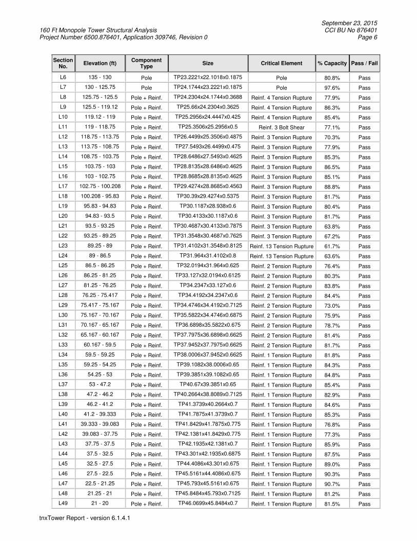
Table 5 - Section Capacity (Summary)
Section No.
Elevation (ft) Component
Type Size Critical Element % Capacity Pass / Fail
L1 160 - 155 Pole TP17.6204x16.5x0.1875 Pole 7.8% Pass
L2 155 - 150 Pole TP18.7407x17.6204x0.1875 Pole 18.3% Pass
L3 150 - 145 Pole TP19.8611x18.7407x0.1875 Pole 37.1% Pass
L4 145 - 140 Pole TP20.9814x19.8611x0.1875 Pole 52.0% Pass
L5 140 - 135 Pole TP22.1018x20.9814x0.1875 Pole 67.5% Pass
September 23, 2015 160 Ft Monopole Tower Structural Analysis CCI BU No 876401 Project Number 6500.876401, Application 309746, Revision 0 Page 6
tnxTower Report - version 6.1.4.1
Section No.
Elevation (ft) Component
Type Size Critical Element % Capacity Pass / Fail
L6 135 - 130 Pole TP23.2221x22.1018x0.1875 Pole 80.8% Pass
L7 130 - 125.75 Pole TP24.1744x23.2221x0.1875 Pole 97.6% Pass
L8 125.75 - 125.5 Pole + Reinf. TP24.2304x24.1744x0.3688 Reinf. 4 Tension Rupture 77.9% Pass
L9 125.5 - 119.12 Pole + Reinf. TP25.66x24.2304x0.3625 Reinf. 4 Tension Rupture 86.3% Pass
L10 119.12 - 119 Pole + Reinf. TP25.2956x24.4447x0.425 Reinf. 4 Tension Rupture 85.4% Pass
L11 119 - 118.75 Pole + Reinf. TP25.3506x25.2956x0.5 Reinf. 3 Bolt Shear 77.1% Pass
L12 118.75 - 113.75 Pole + Reinf. TP26.4499x25.3506x0.4875 Reinf. 3 Tension Rupture 70.3% Pass
L13 113.75 - 108.75 Pole + Reinf. TP27.5493x26.4499x0.475 Reinf. 3 Tension Rupture 77.9% Pass
L14 108.75 - 103.75 Pole + Reinf. TP28.6486x27.5493x0.4625 Reinf. 3 Tension Rupture 85.3% Pass
L15 103.75 - 103 Pole + Reinf. TP28.8135x28.6486x0.4625 Reinf. 3 Tension Rupture 86.5% Pass
L16 103 - 102.75 Pole + Reinf. TP28.8685x28.8135x0.4625 Reinf. 3 Tension Rupture 85.1% Pass
L17 102.75 - 100.208 Pole + Reinf. TP29.4274x28.8685x0.4563 Reinf. 3 Tension Rupture 88.8% Pass
L18 100.208 - 95.83 Pole + Reinf. TP30.39x29.4274x0.5375 Reinf. 3 Tension Rupture 81.7% Pass
L19 95.83 - 94.83 Pole + Reinf. TP30.1187x28.938x0.6 Reinf. 3 Tension Rupture 80.4% Pass
L20 94.83 - 93.5 Pole + Reinf. TP30.4133x30.1187x0.6 Reinf. 3 Tension Rupture 81.7% Pass
L21 93.5 - 93.25 Pole + Reinf. TP30.4687x30.4133x0.7875 Reinf. 3 Tension Rupture 63.8% Pass
L22 93.25 - 89.25 Pole + Reinf. TP31.3548x30.4687x0.7625 Reinf. 3 Tension Rupture 67.2% Pass
L23 89.25 - 89 Pole + Reinf. TP31.4102x31.3548x0.8125 Reinf. 13 Tension Rupture 61.7% Pass
L24 89 - 86.5 Pole + Reinf. TP31.964x31.4102x0.8 Reinf. 13 Tension Rupture 63.6% Pass
L25 86.5 - 86.25 Pole + Reinf. TP32.0194x31.964x0.625 Reinf. 2 Tension Rupture 76.4% Pass
L26 86.25 - 81.25 Pole + Reinf. TP33.127x32.0194x0.6125 Reinf. 2 Tension Rupture 80.3% Pass
L27 81.25 - 76.25 Pole + Reinf. TP34.2347x33.127x0.6 Reinf. 2 Tension Rupture 83.8% Pass
L28 76.25 - 75.417 Pole + Reinf. TP34.4192x34.2347x0.6 Reinf. 2 Tension Rupture 84.4% Pass
L29 75.417 - 75.167 Pole + Reinf. TP34.4746x34.4192x0.7125 Reinf. 2 Tension Rupture 73.0% Pass
L30 75.167 - 70.167 Pole + Reinf. TP35.5822x34.4746x0.6875 Reinf. 2 Tension Rupture 75.9% Pass
L31 70.167 - 65.167 Pole + Reinf. TP36.6898x35.5822x0.675 Reinf. 2 Tension Rupture 78.7% Pass
L32 65.167 - 60.167 Pole + Reinf. TP37.7975x36.6898x0.6625 Reinf. 2 Tension Rupture 81.4% Pass
L33 60.167 - 59.5 Pole + Reinf. TP37.9452x37.7975x0.6625 Reinf. 2 Tension Rupture 81.7% Pass
L34 59.5 - 59.25 Pole + Reinf. TP38.0006x37.9452x0.6625 Reinf. 1 Tension Rupture 81.8% Pass
L35 59.25 - 54.25 Pole + Reinf. TP39.1082x38.0006x0.65 Reinf. 1 Tension Rupture 84.3% Pass
L36 54.25 - 53 Pole + Reinf. TP39.3851x39.1082x0.65 Reinf. 1 Tension Rupture 84.8% Pass
L37 53 - 47.2 Pole + Reinf. TP40.67x39.3851x0.65 Reinf. 1 Tension Rupture 85.4% Pass
L38 47.2 - 46.2 Pole + Reinf. TP40.2664x38.8089x0.7125 Reinf. 1 Tension Rupture 82.9% Pass
L39 46.2 - 41.2 Pole + Reinf. TP41.3739x40.2664x0.7 Reinf. 1 Tension Rupture 84.6% Pass
L40 41.2 - 39.333 Pole + Reinf. TP41.7875x41.3739x0.7 Reinf. 1 Tension Rupture 85.3% Pass
L41 39.333 - 39.083 Pole + Reinf. TP41.8429x41.7875x0.775 Reinf. 1 Tension Rupture 76.8% Pass
L42 39.083 - 37.75 Pole + Reinf. TP42.1381x41.8429x0.775 Reinf. 1 Tension Rupture 77.3% Pass
L43 37.75 - 37.5 Pole + Reinf. TP42.1935x42.1381x0.7 Reinf. 1 Tension Rupture 85.9% Pass
L44 37.5 - 32.5 Pole + Reinf. TP43.301x42.1935x0.6875 Reinf. 1 Tension Rupture 87.5% Pass
L45 32.5 - 27.5 Pole + Reinf. TP44.4086x43.301x0.675 Reinf. 1 Tension Rupture 89.0% Pass
L46 27.5 - 22.5 Pole + Reinf. TP45.5161x44.4086x0.675 Reinf. 1 Tension Rupture 90.3% Pass
L47 22.5 - 21.25 Pole + Reinf. TP45.793x45.5161x0.675 Reinf. 1 Tension Rupture 90.7% Pass
L48 21.25 - 21 Pole + Reinf. TP45.8484x45.793x0.7125 Reinf. 1 Tension Rupture 81.2% Pass
L49 21 - 20 Pole + Reinf. TP46.0699x45.8484x0.7 Reinf. 1 Tension Rupture 81.5% Pass

September 23, 2015 160 Ft Monopole Tower Structural Analysis CCI BU No 876401 Project Number 6500.876401, Application 309746, Revision 0 Page 7
tnxTower Report - version 6.1.4.1
Section No.
Elevation (ft) Component
Type Size Critical Element % Capacity Pass / Fail
L50 20 - 19.75 Pole + Reinf. TP46.1252x46.0699x0.775 Reinf. 1 Tension Rupture 77.8% Pass
L51 19.75 - 17 Pole + Reinf. TP46.7344x46.1252x0.775 Reinf. 1 Tension Rupture 78.5% Pass
L52 17 - 16.75 Pole + Reinf. TP46.7898x46.7344x0.775 Reinf. 1 Tension Rupture 78.6% Pass
L53 16.75 - 11.75 Pole + Reinf. TP47.8973x46.7898x0.7625 Reinf. 1 Tension Rupture 79.8% Pass
L54 11.75 - 6.75 Pole + Reinf. TP49.0048x47.8973x0.75 Reinf. 1 Tension Rupture 80.9% Pass
L55 6.75 - 1.75 Pole + Reinf. TP50.1124x49.0048x0.7375 Reinf. 1 Tension Rupture 82.0% Pass
L56 1.75 - 0 Pole + Reinf. TP50.5x50.1124x0.7375 Reinf. 1 Tension Rupture 82.4% Pass
Summary
Pole 97.6% Pass
Reinforcement 90.7% Pass
Overall 97.6% Pass
Table 6 - Tower Component Stresses vs. Capacity – LC7
Notes Component Elevation (ft) % Capacity Pass / Fail
1 Anchor Rods 0 65.8 Pass
1 Base Plate 0 62.3 Pass
1 Base Foundation 0 69.3 Pass
1 Base Foundation Soil Interaction
0 50.5 Pass
Structure Rating (max from all components) = 97.6%
Notes: 1) See additional documentation in “Appendix C – Additional Calculations” for calculations supporting the % capacity
consumed. 4.1) Recommendations
The tower and its foundation have sufficient capacity to carry the existing, reserved, and proposed loads. No modifications are required at this time.

September 23, 2015 160 Ft Monopole Tower Structural Analysis CCI BU No 876401 Project Number 6500.876401, Application 309746, Revision 0 Page 8
tnxTower Report - version 6.1.4.1
APPENDIX A
TNXTOWER OUTPUT

TECTONIC
1279 Route 300
Newburgh, NY 12550 Phone: (845) 567-6656
FAX: (845) 567-8703
Job: 6500.876401
Project: BU 876401 - TOWN OF PLAINFIELD/SSUSA
Client: Crown Castle Drawn by: Veronica Elson App'd:
Code: TIA/EIA-222-F Date: 09/23/15 Scale: NTS Path:
G:\Newburgh\Projects\6500 Crown SA\876401\Structural\Reinf\Reinf.6500.876401.eri Dwg No. E-1
160.0 ft
155.0 ft
150.0 ft
145.0 ft
140.0 ft
135.0 ft
130.0 ft
125.8 ft
119.1 ft
113.8 ft
108.8 ft
103.8 ft
100.2 ft
95.8 ft
93.5 ft
89.3 ft
86.5 ft
81.3 ft
76.3 ft
70.2 ft
65.2 ft
60.2 ft
54.3 ft
47.2 ft
41.2 ft
39.3 ft37.8 ft
32.5 ft
27.5 ft
22.5 ft
20.0 ft
17.0 ft
11.8 ft
6.8 ft
1.8 ft
0.0 ft
REACTIONS - 85 mph WIND
TORQUE 1 kip-ft
39 K
SHEAR
4163 kip-ft
MOMENT
52 K
AXIAL
38 mph WIND - 1.0000 in ICETORQUE 0 kip-ft
11 K
SHEAR
1164 kip-ft
MOMENT
70 K
AXIAL
S
ectio
n1
23
45
67
89
10
11
12
13
14
15
16
17
18
19
20
21
22
23
24
25
26
27
28
29
30
31
32
33
34
35
36
37
38
39
40
41
42
43
44
45
46
47
48
49
50
51
52
53
54
55
56
L
en
gth
(ft)
5.0
05
.00
5.0
05
.00
5.0
05
.00
4.2
50
.25
6.3
83
.87
0.2
55
.00
5.0
05
.00
0.7
50
.25
2.5
44
.38
5.3
31
.33
0.2
54
.00
0.2
52
.50
0.2
55
.00
5.0
00
.83
0.2
55
.00
5.0
05
.00
0.6
70
.25
5.0
01
.25
5.8
06
.58
5.0
01
.87
0.2
51
.33
0.2
55
.00
5.0
05
.00
1.2
50
.25
1.0
00
.25
2.7
50
.25
5.0
05
.00
5.0
01
.75
N
um
be
r o
f S
ide
s1
81
81
81
81
81
81
81
81
81
81
81
81
81
81
81
81
81
81
81
81
81
81
81
81
81
81
81
81
81
81
81
81
81
81
81
81
81
81
81
81
81
81
81
81
81
81
81
81
81
81
81
81
81
81
81
8
T
hic
kn
ess (
in)
0.1
87
50
.18
75
0.1
87
50
.18
75
0.1
87
50
.18
75
0.1
87
50
.36
88
0.3
62
50
.42
50
0.5
00
00
.48
75
0.4
75
00
.46
25
0.4
62
50
.46
25
0.4
56
20
.53
75
0.6
00
00
.60
00
0.7
87
50
.76
25
0.8
12
50
.80
00
0.6
25
00
.61
25
0.6
00
00
.60
00
0.7
12
50
.68
75
0.6
75
00
.66
25
0.6
62
50
.66
25
0.6
50
00
.65
00
0.6
50
00
.71
25
0.7
00
00
.70
00
0.7
75
00
.77
50
0.7
00
00
.68
75
0.6
75
00
.67
50
0.6
75
00
.71
25
0.7
00
00
.77
50
0.7
75
00
.77
50
0.7
62
50
.75
00
0.7
37
50
.73
75
S
ocke
t L
en
gth
(ft)
3.7
54
.33
5.5
8
T
op
Dia
(in
)1
6.5
00
01
7.6
20
41
8.7
40
71
9.8
61
12
0.9
81
42
2.1
01
82
3.2
22
12
4.1
74
42
4.2
30
42
4.4
44
72
5.2
95
62
5.3
50
62
6.4
49
92
7.5
49
32
8.6
48
62
8.8
13
52
8.8
68
52
9.4
27
42
8.9
38
03
0.1
18
73
0.4
13
33
0.4
68
73
1.3
54
83
1.4
10
23
1.9
64
03
2.0
19
43
3.1
27
03
4.2
34
73
4.4
19
23
4.4
74
63
5.5
82
23
6.6
89
83
7.7
97
53
7.9
45
23
8.0
00
63
9.1
08
23
9.3
85
13
8.8
08
94
0.2
66
44
1.3
73
94
1.7
87
54
1.8
42
94
2.1
38
14
2.1
93
54
3.3
01
04
4.4
08
64
5.5
16
14
5.7
93
04
5.8
48
44
6.0
69
94
6.1
25
24
6.7
34
44
6.7
89
84
7.8
97
34
9.0
04
85
0.1
12
4
B
ot D
ia (
in)
17
.62
04
18
.74
07
19
.86
11
20
.98
14
22
.10
18
23
.22
21
24
.17
44
24
.23
04
25
.66
00
25
.29
56
25
.35
06
26
.44
99
27
.54
93
28
.64
86
28
.81
35
28
.86
85
29
.42
74
30
.39
00
30
.11
87
30
.41
33
30
.46
87
31
.35
48
31
.41
02
31
.96
40
32
.01
94
33
.12
70
34
.23
47
34
.41
92
34
.47
46
35
.58
22
36
.68
98
37
.79
75
37
.94
52
38
.00
06
39
.10
82
39
.38
51
40
.67
00
40
.26
64
41
.37
39
41
.78
75
41
.84
29
42
.13
81
42
.19
35
43
.30
10
44
.40
86
45
.51
61
45
.79
30
45
.84
84
46
.06
99
46
.12
52
46
.73
44
46
.78
98
47
.89
73
49
.00
48
50
.11
24
50
.50
00
G
rad
eA
57
2-6
5
W
eig
ht (K
)0
.20
.20
.20
.20
.20
.20
.20
.00
.60
.40
.00
.60
.60
.60
.10
.00
.40
.81
.00
.30
.11
.00
.10
.60
.11
.11
.10
.20
.11
.31
.31
.30
.20
.11
.30
.31
.71
.91
.50
.60
.10
.40
.11
.51
.61
.60
.40
.10
.40
.11
.10
.12
.02
.02
.00
.73
6.8
APXVSPP18-C-A20 w/ Mount Pipe 159 APXVSPP18-C-A20 w/ Mount Pipe 159 APXVSPP18-C-A20 w/ Mount Pipe 159 (3) 7' x 2" STD Pipe 159 (3) 7' x 2" STD Pipe 159 (3) 7' x 2" STD Pipe 159 LP 712-1 159 800MHz 2X50W RRH W/FILTER 157 800MHz 2X50W RRH W/FILTER 157 800MHz 2X50W RRH W/FILTER 157 PCS 1900MHz 4x45W-65MHz 157 PCS 1900MHz 4x45W-65MHz 157 PCS 1900MHz 4x45W-65MHz 157 SO 102-3 157 (2) TME-RRUS-11 152 (2) TME-RRUS-11 152 (2) TME-RRUS-11 152 SO 102-3 152 (2) 7770.00 w/ Mount Pipe 150 (2) 7770.00 w/ Mount Pipe 150 (2) 7770.00 w/ Mount Pipe 150 AM-X-CD-17-65-00T-RET w/ Mount Pipe
150 AM-X-CD-17-65-00T-RET w/ Mount Pipe
150 AM-X-CD-17-65-00T-RET w/ Mount Pipe
150 (2) LGP21401 150 (2) LGP21401 150 (2) LGP21401 150 (2) LGP21901 150 (2) LGP21901 150 (2) LGP21901 150 DC6-48-60-18-8F 150 LP 303-1 150 APXV18-203219-C-A20 w/ Mount Pipe 139 APXV18-203219-C-A20 w/ Mount Pipe 139 APXV18-203219-C-A20 w/ Mount Pipe 139 LNX-6512DS-VTM w/ Mount Pipe 139 LNX-6512DS-VTM w/ Mount Pipe 139 LNX-6512DS-VTM w/ Mount Pipe 139 TMAT7LA-11A 139 TMAT7LA-11A 139 TMAT7LA-11A 139 ATBT-BOTTOM-24V 139 ATBT-BOTTOM-24V 139 ATBT-BOTTOM-24V 139 5' x 2" STD Pipe 139 5' x 2" STD Pipe 139 5' x 2" STD Pipe 139 TA 602-3 139 (2) LNX-6514DS-A1M w/ Mount Pipe 127 (2) LNX-6514DS-A1M w/ Mount Pipe 127 (2) LNX-6514DS-A1M w/ Mount Pipe 127 (2) HBXX-6517DS-A2M w/ Mount Pipe 127 (2) HBXX-6517DS-A2M w/ Mount Pipe 127 (2) HBXX-6517DS-A2M w/ Mount Pipe 127 RRH2X40-07-U 127 RRH2X40-07-U 127 RRH2X40-07-U 127 RRH2X60-AWS 127 RRH2X60-AWS 127 RRH2X60-AWS 127 RRH2X60-PCS 127 RRH2X60-PCS 127 RRH2X60-PCS 127 DB-T1-6Z-8AB-0Z 127 DB-T1-6Z-8AB-0Z 127 LP 303-1 127 DB589 109 SO 701-1 109 SO 201-1 109 (2) 800 10504 w/ Mount Pipe 105 (2) 800 10504 w/ Mount Pipe 105 (2) 800 10504 w/ Mount Pipe 105 (2) 860 10025 105 (2) 860 10025 105 (2) 860 10025 105 SM 506-3 105DESIGNED APPURTENANCE LOADING
TYPE TYPEELEVATION ELEVATION APXVSPP18-C-A20 w/ Mount Pipe 159
APXVSPP18-C-A20 w/ Mount Pipe 159
APXVSPP18-C-A20 w/ Mount Pipe 159
(3) 7' x 2" STD Pipe 159
(3) 7' x 2" STD Pipe 159
(3) 7' x 2" STD Pipe 159
LP 712-1 159
800MHz 2X50W RRH W/FILTER 157
800MHz 2X50W RRH W/FILTER 157
800MHz 2X50W RRH W/FILTER 157
PCS 1900MHz 4x45W-65MHz 157
PCS 1900MHz 4x45W-65MHz 157
PCS 1900MHz 4x45W-65MHz 157
SO 102-3 157
(2) TME-RRUS-11 152
(2) TME-RRUS-11 152
(2) TME-RRUS-11 152
SO 102-3 152
(2) 7770.00 w/ Mount Pipe 150
(2) 7770.00 w/ Mount Pipe 150
(2) 7770.00 w/ Mount Pipe 150
AM-X-CD-17-65-00T-RET w/ Mount Pipe
150
AM-X-CD-17-65-00T-RET w/ Mount Pipe
150
AM-X-CD-17-65-00T-RET w/ Mount Pipe
150
(2) LGP21401 150
(2) LGP21401 150
(2) LGP21401 150
(2) LGP21901 150
(2) LGP21901 150
(2) LGP21901 150
DC6-48-60-18-8F 150
LP 303-1 150
APXV18-203219-C-A20 w/ Mount Pipe 139
APXV18-203219-C-A20 w/ Mount Pipe 139
APXV18-203219-C-A20 w/ Mount Pipe 139
LNX-6512DS-VTM w/ Mount Pipe 139
LNX-6512DS-VTM w/ Mount Pipe 139
LNX-6512DS-VTM w/ Mount Pipe 139
TMAT7LA-11A 139
TMAT7LA-11A 139
TMAT7LA-11A 139
ATBT-BOTTOM-24V 139
ATBT-BOTTOM-24V 139
ATBT-BOTTOM-24V 139
5' x 2" STD Pipe 139
5' x 2" STD Pipe 139
5' x 2" STD Pipe 139
TA 602-3 139
(2) LNX-6514DS-A1M w/ Mount Pipe 127
(2) LNX-6514DS-A1M w/ Mount Pipe 127
(2) LNX-6514DS-A1M w/ Mount Pipe 127
(2) HBXX-6517DS-A2M w/ Mount Pipe 127
(2) HBXX-6517DS-A2M w/ Mount Pipe 127
(2) HBXX-6517DS-A2M w/ Mount Pipe 127
RRH2X40-07-U 127
RRH2X40-07-U 127
RRH2X40-07-U 127
RRH2X60-AWS 127
RRH2X60-AWS 127
RRH2X60-AWS 127
RRH2X60-PCS 127
RRH2X60-PCS 127
RRH2X60-PCS 127
DB-T1-6Z-8AB-0Z 127
DB-T1-6Z-8AB-0Z 127
LP 303-1 127
DB589 109
SO 701-1 109
SO 201-1 109
(2) 800 10504 w/ Mount Pipe 105
(2) 800 10504 w/ Mount Pipe 105
(2) 800 10504 w/ Mount Pipe 105
(2) 860 10025 105
(2) 860 10025 105
(2) 860 10025 105
SM 506-3 105
MATERIAL STRENGTHGRADE GRADEFy FyFu Fu
A572-65 65 ksi 80 ksi
TOWER DESIGN NOTES1. Tower is located in Windham County, Connecticut.2. Tower designed for a 85 mph basic wind in accordance with the TIA/EIA-222-F Standard.3. Tower is also designed for a 38 mph basic wind with 1.00 in ice. Ice is considered to
increase in thickness with height.4. Deflections are based upon a 50 mph wind.5. TOWER RATING: 97.6%

September 23, 2015 160 Ft Monopole Tower Structural Analysis CCI BU No 876401 Project Number 6500.876401, Application 309746, Revision 0 Page 9
tnxTower Report - version 6.1.4.1
Tower Input Data
There is a pole section. This tower is designed using the TIA/EIA-222-F standard. The following design criteria apply:
4) Tower is located in Windham County, Connecticut. 5) Basic wind speed of 85 mph. 6) Nominal ice thickness of 1.0000 in. 7) Ice thickness is considered to increase with height. 8) Ice density of 56 pcf. 9) A wind speed of 38 mph is used in combination with ice. 10) Deflections calculated using a wind speed of 50 mph. 11) TOWER RATING: 90.7%. 12) A non-linear (P-delta) analysis was used. 13) Pressures are calculated at each section. 14) Stress ratio used in pole design is 1.333. 15) Local bending stresses due to climbing loads, feed line supports, and appurtenance mounts are
not considered.
Tapered Pole Section Geometry
Section Elevation
ft
Section Length
ft
Splice Length
ft
Number of
Sides
Top Diameter
in
Bottom Diameter
in
Wall Thickness
in
Bend Radius
in
Pole Grade
L1 160.00-155.00 5.00 0.00 18 16.5000 17.6204 0.1875 0.7500 A572-65 (65 ksi)
L2 155.00-150.00 5.00 0.00 18 17.6204 18.7407 0.1875 0.7500 A572-65 (65 ksi)
L3 150.00-145.00 5.00 0.00 18 18.7407 19.8611 0.1875 0.7500 A572-65 (65 ksi)
L4 145.00-140.00 5.00 0.00 18 19.8611 20.9814 0.1875 0.7500 A572-65 (65 ksi)
L5 140.00-135.00 5.00 0.00 18 20.9814 22.1018 0.1875 0.7500 A572-65 (65 ksi)
L6 135.00-130.00 5.00 0.00 18 22.1018 23.2221 0.1875 0.7500 A572-65 (65 ksi)
L7 130.00-125.75 4.25 0.00 18 23.2221 24.1744 0.1875 0.7500 A572-65 (65 ksi)
L8 125.75-125.50 0.25 0.00 18 24.1744 24.2304 0.3688 1.4750 A572-65 (65 ksi)
L9 125.50-119.12 6.38 3.75 18 24.2304 25.6600 0.3625 1.4500 A572-65 (65 ksi)
L10 119.12-119.00 3.87 0.00 18 24.4447 25.2956 0.4250 1.7000 A572-65 (65 ksi)
L11 119.00-118.75 0.25 0.00 18 25.2956 25.3506 0.5000 2.0000 A572-65 (65 ksi)
L12 118.75-113.75 5.00 0.00 18 25.3506 26.4499 0.4875 1.9500 A572-65 (65 ksi)
L13 113.75-108.75 5.00 0.00 18 26.4499 27.5493 0.4750 1.9000 A572-65 (65 ksi)
L14 108.75-103.75 5.00 0.00 18 27.5493 28.6486 0.4625 1.8500 A572-65 (65 ksi)
L15 103.75-103.00 0.75 0.00 18 28.6486 28.8135 0.4625 1.8500 A572-65 (65 ksi)
L16 103.00-102.75 0.25 0.00 18 28.8135 28.8685 0.4625 1.8500 A572-65 (65 ksi)
L17 102.75-100.21 2.54 0.00 18 28.8685 29.4274 0.4562 1.8250 A572-65 (65 ksi)
L18 100.21-95.83 4.38 4.33 18 29.4274 30.3900 0.5375 2.1500 A572-65 (65 ksi)
L19 95.83-94.83 5.33 0.00 18 28.9380 30.1187 0.6000 2.4000 A572-65 (65 ksi)
L20 94.83-93.50 1.33 0.00 18 30.1187 30.4133 0.6000 2.4000 A572-65

September 23, 2015 160 Ft Monopole Tower Structural Analysis CCI BU No 876401 Project Number 6500.876401, Application 309746, Revision 0 Page 10
tnxTower Report - version 6.1.4.1
Section Elevation
ft
Section Length
ft
Splice Length
ft
Number of
Sides
Top Diameter
in
Bottom Diameter
in
Wall Thickness
in
Bend Radius
in
Pole Grade
(65 ksi) L21 93.50-93.25 0.25 0.00 18 30.4133 30.4687 0.7875 3.1500 A572-65
(65 ksi) L22 93.25-89.25 4.00 0.00 18 30.4687 31.3548 0.7625 3.0500 A572-65
(65 ksi) L23 89.25-89.00 0.25 0.00 18 31.3548 31.4102 0.8125 3.2500 A572-65
(65 ksi) L24 89.00-86.50 2.50 0.00 18 31.4102 31.9640 0.8000 3.2000 A572-65
(65 ksi) L25 86.50-86.25 0.25 0.00 18 31.9640 32.0194 0.6250 2.5000 A572-65
(65 ksi) L26 86.25-81.25 5.00 0.00 18 32.0194 33.1270 0.6125 2.4500 A572-65
(65 ksi) L27 81.25-76.25 5.00 0.00 18 33.1270 34.2347 0.6000 2.4000 A572-65
(65 ksi) L28 76.25-75.42 0.83 0.00 18 34.2347 34.4192 0.6000 2.4000 A572-65
(65 ksi) L29 75.42-75.17 0.25 0.00 18 34.4192 34.4746 0.7125 2.8500 A572-65
(65 ksi) L30 75.17-70.17 5.00 0.00 18 34.4746 35.5822 0.6875 2.7500 A572-65
(65 ksi) L31 70.17-65.17 5.00 0.00 18 35.5822 36.6898 0.6750 2.7000 A572-65
(65 ksi) L32 65.17-60.17 5.00 0.00 18 36.6898 37.7975 0.6625 2.6500 A572-65
(65 ksi) L33 60.17-59.50 0.67 0.00 18 37.7975 37.9452 0.6625 2.6500 A572-65
(65 ksi) L34 59.50-59.25 0.25 0.00 18 37.9452 38.0006 0.6625 2.6500 A572-65
(65 ksi) L35 59.25-54.25 5.00 0.00 18 38.0006 39.1082 0.6500 2.6000 A572-65
(65 ksi) L36 54.25-53.00 1.25 0.00 18 39.1082 39.3851 0.6500 2.6000 A572-65
(65 ksi) L37 53.00-47.20 5.80 5.58 18 39.3851 40.6700 0.6500 2.6000 A572-65
(65 ksi) L38 47.20-46.20 6.58 0.00 18 38.8089 40.2664 0.7125 2.8500 A572-65
(65 ksi) L39 46.20-41.20 5.00 0.00 18 40.2664 41.3739 0.7000 2.8000 A572-65
(65 ksi) L40 41.20-39.33 1.87 0.00 18 41.3739 41.7875 0.7000 2.8000 A572-65
(65 ksi) L41 39.33-39.08 0.25 0.00 18 41.7875 41.8429 0.7750 3.1000 A572-65
(65 ksi) L42 39.08-37.75 1.33 0.00 18 41.8429 42.1381 0.7750 3.1000 A572-65
(65 ksi) L43 37.75-37.50 0.25 0.00 18 42.1381 42.1935 0.7000 2.8000 A572-65
(65 ksi) L44 37.50-32.50 5.00 0.00 18 42.1935 43.3010 0.6875 2.7500 A572-65
(65 ksi) L45 32.50-27.50 5.00 0.00 18 43.3010 44.4086 0.6750 2.7000 A572-65
(65 ksi) L46 27.50-22.50 5.00 0.00 18 44.4086 45.5161 0.6750 2.7000 A572-65
(65 ksi) L47 22.50-21.25 1.25 0.00 18 45.5161 45.7930 0.6750 2.7000 A572-65
(65 ksi) L48 21.25-21.00 0.25 0.00 18 45.7930 45.8484 0.7125 2.8500 A572-65
(65 ksi) L49 21.00-20.00 1.00 0.00 18 45.8484 46.0699 0.7000 2.8000 A572-65
(65 ksi) L50 20.00-19.75 0.25 0.00 18 46.0699 46.1252 0.7750 3.1000 A572-65
(65 ksi) L51 19.75-17.00 2.75 0.00 18 46.1252 46.7344 0.7750 3.1000 A572-65
(65 ksi) L52 17.00-16.75 0.25 0.00 18 46.7344 46.7898 0.7750 3.1000 A572-65
(65 ksi) L53 16.75-11.75 5.00 0.00 18 46.7898 47.8973 0.7625 3.0500 A572-65
(65 ksi) L54 11.75-6.75 5.00 0.00 18 47.8973 49.0048 0.7500 3.0000 A572-65
(65 ksi)

September 23, 2015 160 Ft Monopole Tower Structural Analysis CCI BU No 876401 Project Number 6500.876401, Application 309746, Revision 0 Page 11
tnxTower Report - version 6.1.4.1
Section Elevation
ft
Section Length
ft
Splice Length
ft
Number of
Sides
Top Diameter
in
Bottom Diameter
in
Wall Thickness
in
Bend Radius
in
Pole Grade
L55 6.75-1.75 5.00 0.00 18 49.0048 50.1124 0.7375 2.9500 A572-65 (65 ksi)
L56 1.75-0.00 1.75 18 50.1124 50.5000 0.7375 2.9500 A572-65 (65 ksi)
Tapered Pole Properties
Section Tip Dia. in
Area in2
I in4
r in
C in
I/C in3
J in4
It/Q in2
w in
w/t
L1 16.7545 9.7080 326.3677 5.7909 8.3820 38.9367 653.1649 4.8549 2.5740 13.728 17.8922 10.3747 398.3373 6.1887 8.9511 44.5013 797.1988 5.1883 2.7712 14.78
L2 17.8922 10.3747 398.3373 6.1887 8.9511 44.5013 797.1988 5.1883 2.7712 14.78 19.0298 11.0415 480.1782 6.5864 9.5203 50.4374 960.9882 5.5218 2.9684 15.831
L3 19.0298 11.0415 480.1782 6.5864 9.5203 50.4374 960.9882 5.5218 2.9684 15.831 20.1674 11.7082 572.5248 6.9841 10.0894 56.7451 1145.8029 5.8552 3.1655 16.883
L4 20.1674 11.7082 572.5248 6.9841 10.0894 56.7451 1145.8029 5.8552 3.1655 16.883 21.3051 12.3750 676.0115 7.3818 10.6586 63.4243 1352.9124 6.1887 3.3627 17.935
L5 21.3051 12.3750 676.0115 7.3818 10.6586 63.4243 1352.9124 6.1887 3.3627 17.935 22.4427 13.0417 791.2726 7.7796 11.2277 70.4751 1583.5865 6.5221 3.5599 18.986
L6 22.4427 13.0417 791.2726 7.7796 11.2277 70.4751 1583.5865 6.5221 3.5599 18.986 23.5804 13.7085 918.9427 8.1773 11.7968 77.8974 1839.0946 6.8555 3.7571 20.038
L7 23.5804 13.7085 918.9427 8.1773 11.7968 77.8974 1839.0946 6.8555 3.7571 20.038 24.5473 14.2752 1037.6926 8.5154 12.2806 84.4985 2076.7506 7.1390 3.9247 20.932
L8 24.5473 27.8624 1994.8821 8.4510 12.2806 162.4417 3992.3892 13.9339 3.6057 9.778 24.6042 27.9280 2008.9979 8.4709 12.3091 163.2130 4020.6393 13.9667 3.6156 9.805
L9 24.6042 27.4618 1976.4994 8.4731 12.3091 160.5727 3955.5995 13.7335 3.6266 10.004 26.0558 29.1067 2353.3428 8.9806 13.0353 180.5364 4709.7822 14.5561 3.8782 10.698
L10 25.6591 32.4014 2361.7721 8.5270 12.4179 190.1905 4726.6518 16.2038 3.5543 8.363 25.6859 33.5492 2621.7643 8.8291 12.8502 204.0255 5246.9784 16.7778 3.7040 8.715
L11 25.6859 39.3507 3056.6084 8.8024 12.8502 237.8650 6117.2388 19.6791 3.5720 7.144 25.7417 39.4379 3076.9813 8.8220 12.8781 238.9313 6158.0114 19.7227 3.5817 7.163
L12 25.7417 38.4713 3004.5862 8.8264 12.8781 233.3097 6013.1259 19.2393 3.6037 7.392 26.8580 40.1723 3421.0205 9.2167 13.4366 254.6052 6846.5424 20.0900 3.7972 7.789
L13 26.8580 39.1611 3338.1189 9.2211 13.4366 248.4353 6680.6302 19.5843 3.8192 8.04 27.9743 40.8186 3780.1513 9.6114 13.9950 270.1065 7565.2767 20.4132 4.0127 8.448
L14 27.9743 39.7627 3685.7740 9.6158 13.9950 263.3629 7376.3979 19.8851 4.0347 8.724 29.0906 41.3765 4153.0076 10.0061 14.5535 285.3613 8311.4798 20.6922 4.2282 9.142
L15 29.0906 41.3765 4153.0076 10.0061 14.5535 285.3613 8311.4798 20.6922 4.2282 9.142 29.2580 41.6186 4226.3259 10.0646 14.6373 288.7372 8458.2129 20.8133 4.2572 9.205
L16 29.2580 41.6186 4226.3259 10.0646 14.6373 288.7372 8458.2129 20.8133 4.2572 9.205 29.3138 41.6993 4250.9557 10.0841 14.6652 289.8669 8507.5050 20.8536 4.2669 9.226
L17 29.3138 41.1449 4196.2790 10.0864 14.6652 286.1385 8398.0796 20.5763 4.2779 9.376 29.8814 41.9542 4448.8219 10.2848 14.9491 297.5975 8903.4976 20.9811 4.3762 9.592
L18 29.8814 49.2869 5197.1053 10.2559 14.9491 347.6528 10401.0492
24.6481 4.2332 7.876
30.8588 50.9291 5734.0960 10.5976 15.4381 371.4245 11475.7371
25.4694 4.4026 8.191
L19 30.3584 53.9668 5475.2210 10.0600 14.7005 372.4517 10957.6465
26.9885 4.0371 6.728
30.5833 56.2154 6188.5281 10.4791 15.3003 404.4710 12385.1993
28.1130 4.2449 7.075
L20 30.5833 56.2154 6188.5281 10.4791 15.3003 404.4710 12385.1993
28.1130 4.2449 7.075
30.8825 56.7765 6375.6894 10.5837 15.4500 412.6667 12759.7680
28.3936 4.2967 7.161
L21 30.8825 74.0505 8211.1990 10.5172 15.4500 531.4701 16433.2026
37.0323 3.9667 5.037
30.9387 74.1889 8257.3344 10.5368 15.4781 533.4848 16525.5341
37.1015 3.9765 5.05
L22 30.9387 71.8942 8015.4165 10.5457 15.4781 517.8551 16041.3799
35.9539 4.0205 5.273
31.8385 74.0388 8754.2993 10.8603 15.9282 549.6084 17520.1177
37.0264 4.1764 5.477
L23 31.8385 78.7648 9282.6877 10.8425 15.9282 582.7815 18577.5898
39.3899 4.0884 5.032

September 23, 2015 160 Ft Monopole Tower Structural Analysis CCI BU No 876401 Project Number 6500.876401, Application 309746, Revision 0 Page 12
tnxTower Report - version 6.1.4.1
Section Tip Dia. in
Area in2
I in4
r in
C in
I/C in3
J in4
It/Q in2
w in
w/t
31.8948 78.9076 9333.2755 10.8622 15.9564 584.9243 18678.8319
39.4613 4.0982 5.044
L24 31.8948 77.7254 9200.9540 10.8666 15.9564 576.6316 18414.0148
38.8701 4.1202 5.15
32.4571 79.1317 9709.4494 11.0632 16.2377 597.9565 19431.6748
39.5734 4.2177 5.272
L25 32.4571 62.1688 7714.0144 11.1254 16.2377 475.0676 15438.1791
31.0903 4.5257 7.241
32.5133 62.2786 7754.9828 11.1450 16.2659 476.7646 15520.1698
31.1452 4.5354 7.257
L26 32.5133 61.0574 7608.9647 11.1494 16.2659 467.7876 15227.9414
30.5345 4.5574 7.441
33.6381 63.2107 8442.7293 11.5427 16.8285 501.6914 16896.5677
31.6113 4.7524 7.759
L27 33.6381 61.9445 8279.9709 11.5471 16.8285 492.0198 16570.8367
30.9781 4.7744 7.957
34.7628 64.0538 9154.9667 11.9403 17.3912 526.4135 18321.9796
32.0330 4.9693 8.282
L28 34.7628 64.0538 9154.9667 11.9403 17.3912 526.4135 18321.9796
32.0330 4.9693 8.282
34.9502 64.4053 9306.4768 12.0058 17.4849 532.2564 18625.1994
32.2088 5.0018 8.336
L29 34.9502 76.2268 10941.5194
11.9659 17.4849 625.7679 21897.4359
38.1207 4.8038 6.742
35.0064 76.3521 10995.5403
11.9855 17.5131 627.8472 22005.5487
38.1833 4.8135 6.756
L30 35.0064 73.7276 10633.3180
11.9944 17.5131 607.1642 21280.6277
36.8708 4.8575 7.065
36.1311 76.1446 11713.7424
12.3876 18.0758 648.0360 23442.8981
38.0795 5.0525 7.349
L31 36.1311 74.7869 11513.1292
12.3921 18.0758 636.9375 23041.4076
37.4006 5.0745 7.518
37.2558 77.1600 12644.2331
12.7853 18.6384 678.3956 25305.1038
38.5873 5.2694 7.807
L32 37.2558 75.7574 12423.0070
12.7897 18.6384 666.5262 24862.3604
37.8859 5.2914 7.987
38.3806 78.0865 13604.4010
13.1829 19.2011 708.5214 27226.7031
39.0507 5.4864 8.281
L33 38.3806 78.0865 13604.4010
13.1829 19.2011 708.5214 27226.7031
39.0507 5.4864 8.281
38.5306 78.3972 13767.4416
13.2354 19.2762 714.2206 27552.9987
39.2060 5.5124 8.321
L34 38.5306 78.3972 13767.4416
13.2354 19.2762 714.2206 27552.9987
39.2060 5.5124 8.321
38.5868 78.5136 13828.8853
13.2550 19.3043 716.3626 27675.9669
39.2643 5.5221 8.335
L35 38.5868 77.0580 13581.5943
13.2595 19.3043 703.5525 27181.0595
38.5363 5.5441 8.529
39.7115 79.3432 14826.0659
13.6527 19.8670 746.2665 29671.6404
39.6791 5.7391 8.829
L36 39.7115 79.3432 14826.0659
13.6527 19.8670 746.2665 29671.6404
39.6791 5.7391 8.829
39.9927 79.9145 15148.6303
13.7510 20.0077 757.1417 30317.1935
39.9648 5.7878 8.904
L37 39.9927 79.9145 15148.6303
13.7510 20.0077 757.1417 30317.1935
39.9648 5.7878 8.904
41.2974 82.5653 16706.6349
14.2071 20.6604 808.6323 33435.2528
41.2905 6.0139 9.252
L38 40.6626 86.1540 15797.2132
13.5242 19.7149 801.2824 31615.2127
43.0852 5.5764 7.826
40.8876 89.4501 17680.6023
14.0416 20.4553 864.3519 35384.4692
44.7336 5.8329 8.187
L39 40.8876 87.9086 17386.8900
14.0461 20.4553 849.9932 34796.6580
43.9627 5.8549 8.364
42.0122 90.3693 18888.2098
14.4392 21.0180 898.6702 37801.2733
45.1933 6.0498 8.643
L40 42.0122 90.3693 18888.2098
14.4392 21.0180 898.6702 37801.2733
45.1933 6.0498 8.643
42.4321 91.2882 19470.2260
14.5861 21.2280 917.1937 38966.0715
45.6528 6.1226 8.747

September 23, 2015 160 Ft Monopole Tower Structural Analysis CCI BU No 876401 Project Number 6500.876401, Application 309746, Revision 0 Page 13
tnxTower Report - version 6.1.4.1
Section Tip Dia. in
Area in2
I in4
r in
C in
I/C in3
J in4
It/Q in2
w in
w/t
L41 42.4321 100.8846 21438.4920
14.5594 21.2280 1009.9138 42905.1934
50.4519 5.9906 7.73
42.4884 101.0208 21525.4506
14.5791 21.2562 1012.6682 43079.2249
50.5200 6.0003 7.742
L42 42.4884 101.0208 21525.4506
14.5791 21.2562 1012.6682 43079.2249
50.5200 6.0003 7.742
42.7882 101.7471 21993.0855
14.6839 21.4062 1027.4181 44015.1101
50.8832 6.0523 7.809
L43 42.7882 92.0672 19972.9751
14.7105 21.4062 933.0476 39972.2312
46.0424 6.1843 8.835
42.8444 92.1903 20053.1560
14.7302 21.4343 935.5638 40132.6985
46.1039 6.1941 8.849
L44 42.8444 90.5713 19712.8688
14.7346 21.4343 919.6880 39451.6764
45.2942 6.2161 9.042
43.9690 92.9881 21333.3867
15.1278 21.9969 969.8349 42694.8445
46.5029 6.4110 9.325
L45 43.9690 91.3242 20963.9445
15.1322 21.9969 953.0397 41955.4738
45.6708 6.4330 9.53
45.0936 93.6970 22640.8598
15.5254 22.5596 1003.6041 45311.5110
46.8574 6.6279 9.819
L46 45.0936 93.6970 22640.8598
15.5254 22.5596 1003.6041 45311.5110
46.8574 6.6279 9.819
46.2183 96.0698 24404.8971
15.9186 23.1222 1055.4756 48841.9068
48.0440 6.8228 10.108
L47 46.2183 96.0698 24404.8971
15.9186 23.1222 1055.4756 48841.9068
48.0440 6.8228 10.108
46.4994 96.6630 24859.7778
16.0169 23.2628 1068.6477 49752.2667
48.3407 6.8716 10.18
L48 46.4994 101.9484 26175.5003
16.0036 23.2628 1125.2067 52385.4429
50.9839 6.8056 9.552
46.5556 102.0736 26272.0804
16.0232 23.2910 1127.9944 52578.7302
51.0465 6.8153 9.565
L49 46.5556 100.3106 25832.6172
16.0277 23.2910 1109.1260 51699.2256
50.1648 6.8373 9.768
46.7806 100.8028 26214.7051
16.1063 23.4035 1120.1193 52463.9041
50.4110 6.8763 9.823
L50 46.7806 111.4186 28879.7272
16.0797 23.4035 1233.9922 57797.4551
55.7199 6.7443 8.702
46.8368 111.5548 28985.7802
16.0993 23.4316 1237.0367 58009.7006
55.7880 6.7540 8.715
L51 46.8368 111.5548 28985.7802
16.0993 23.4316 1237.0367 58009.7006
55.7880 6.7540 8.715
47.4553 113.0532 30169.5473
16.3156 23.7411 1270.7746 60378.7925
56.5373 6.8613 8.853
L52 47.4553 113.0532 30169.5473
16.3156 23.7411 1270.7746 60378.7925
56.5373 6.8613 8.853
47.5116 113.1894 30278.7330
16.3352 23.7692 1273.8642 60597.3075
56.6055 6.8710 8.866
L53 47.5116 111.3940 29814.6508
16.3397 23.7692 1254.3397 59668.5324
55.7076 6.8930 9.04
48.6362 114.0745 32019.1033
16.7329 24.3318 1315.9350 64080.3382
57.0481 7.0879 9.296
L54 48.6362 112.2341 31519.2631
16.7373 24.3318 1295.3924 63080.0001
56.1277 7.1099 9.48
49.7608 114.8706 33793.0992
17.1305 24.8945 1357.4549 67630.6642
57.4462 7.3049 9.74
L55 49.7608 112.9854 33255.7113
17.1349 24.8945 1335.8683 66555.1814
56.5034 7.3269 9.935
50.8854 115.5779 35597.8789
17.5281 25.4571 1398.3488 71242.5984
57.7999 7.5218 10.199
L56 50.8854 115.5779 35597.8789
17.5281 25.4571 1398.3488 71242.5984
57.7999 7.5218 10.199
51.2790 116.4853 36442.9033
17.6657 25.6540 1420.5544 72933.7592
58.2537 7.5900 10.292
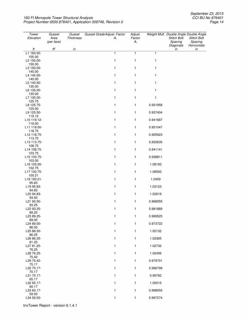
September 23, 2015 160 Ft Monopole Tower Structural Analysis CCI BU No 876401 Project Number 6500.876401, Application 309746, Revision 0 Page 14
tnxTower Report - version 6.1.4.1
Tower Elevation
ft
Gusset Area
(per face)
ft2
Gusset Thickness
in
Gusset Grade Adjust. Factor Af
Adjust. Factor
Ar
Weight Mult.
Double Angle Stitch Bolt Spacing
Diagonals in
Double Angle Stitch Bolt Spacing
Horizontals in
L1 160.00-155.00
1 1 1
L2 155.00-150.00
1 1 1
L3 150.00-145.00
1 1 1
L4 145.00-140.00
1 1 1
L5 140.00-135.00
1 1 1
L6 135.00-130.00
1 1 1
L7 130.00-125.75
1 1 1
L8 125.75-125.50
1 1 0.931958
L9 125.50-119.12
1 1 0.937404
L10 119.12-119.00
1 1 0.941687
L11 119.00-118.75
1 1 0.921047
L12 118.75-113.75
1 1 0.925923
L13 113.75-108.75
1 1 0.932635
L14 108.75-103.75
1 1 0.941141
L15 103.75-103.00
1 1 0.938811
L16 103.00-102.75
1 1 1.08193
L17 102.75-100.21
1 1 1.08593
L18 100.21-95.83
1 1 1.0459
L19 95.83-94.83
1 1 1.03123
L20 94.83-93.50
1 1 1.02619
L21 93.50-93.25
1 1 0.968055
L22 93.25-89.25
1 1 0.981889
L23 89.25-89.00
1 1 0.969525
L24 89.00-86.50
1 1 0.973722
L25 86.50-86.25
1 1 1.02132
L26 86.25-81.25
1 1 1.02365
L27 81.25-76.25
1 1 1.02732
L28 76.25-75.42
1 1 1.02456
L29 75.42-75.17
1 1 0.979701
L30 75.17-70.17
1 1 0.996799
L31 70.17-65.17
1 1 0.99792
L32 65.17-60.17
1 1 1.00015
L33 60.17-59.50
1 1 0.998055
L34 59.50- 1 1 0.997274
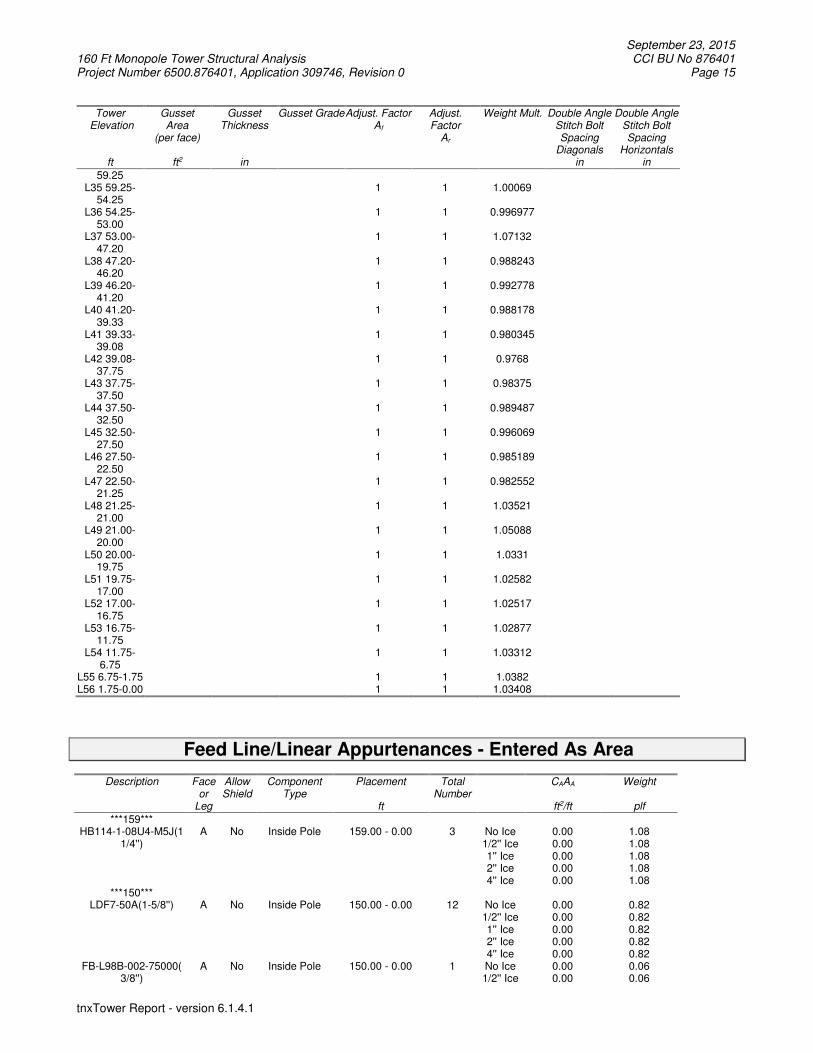
September 23, 2015 160 Ft Monopole Tower Structural Analysis CCI BU No 876401 Project Number 6500.876401, Application 309746, Revision 0 Page 15
tnxTower Report - version 6.1.4.1
Tower Elevation
ft
Gusset Area
(per face)
ft2
Gusset Thickness
in
Gusset Grade Adjust. Factor Af
Adjust. Factor
Ar
Weight Mult.
Double Angle Stitch Bolt Spacing
Diagonals in
Double Angle Stitch Bolt Spacing
Horizontals in
59.25 L35 59.25-
54.25 1 1 1.00069
L36 54.25-53.00
1 1 0.996977
L37 53.00-47.20
1 1 1.07132
L38 47.20-46.20
1 1 0.988243
L39 46.20-41.20
1 1 0.992778
L40 41.20-39.33
1 1 0.988178
L41 39.33-39.08
1 1 0.980345
L42 39.08-37.75
1 1 0.9768
L43 37.75-37.50
1 1 0.98375
L44 37.50-32.50
1 1 0.989487
L45 32.50-27.50
1 1 0.996069
L46 27.50-22.50
1 1 0.985189
L47 22.50-21.25
1 1 0.982552
L48 21.25-21.00
1 1 1.03521
L49 21.00-20.00
1 1 1.05088
L50 20.00-19.75
1 1 1.0331
L51 19.75-17.00
1 1 1.02582
L52 17.00-16.75
1 1 1.02517
L53 16.75-11.75
1 1 1.02877
L54 11.75-6.75
1 1 1.03312
L55 6.75-1.75 1 1 1.0382 L56 1.75-0.00 1 1 1.03408
Feed Line/Linear Appurtenances - Entered As Area
Description Face or
Leg
Allow Shield
Component Type
Placement
ft
Total Number
CAAA
ft2/ft
Weight
plf
***159*** HB114-1-08U4-M5J(1
1/4'') A No Inside Pole 159.00 - 0.00 3 No Ice
1/2'' Ice 1'' Ice 2'' Ice 4'' Ice
0.00 0.00 0.00 0.00 0.00
1.08 1.08 1.08 1.08 1.08
***150*** LDF7-50A(1-5/8'') A No Inside Pole 150.00 - 0.00 12 No Ice
1/2'' Ice 1'' Ice 2'' Ice 4'' Ice
0.00 0.00 0.00 0.00 0.00
0.82 0.82 0.82 0.82 0.82
FB-L98B-002-75000( 3/8'')
A No Inside Pole 150.00 - 0.00 1 No Ice 1/2'' Ice
0.00 0.00
0.06 0.06

September 23, 2015 160 Ft Monopole Tower Structural Analysis CCI BU No 876401 Project Number 6500.876401, Application 309746, Revision 0 Page 16
tnxTower Report - version 6.1.4.1
Description Face or
Leg
Allow Shield
Component Type
Placement
ft
Total Number
CAAA
ft2/ft
Weight
plf
1'' Ice 2'' Ice 4'' Ice
0.00 0.00 0.00
0.06 0.06 0.06
WR-VG122ST-BRDA(7/16)
A No Inside Pole 150.00 - 0.00 2 No Ice 1/2'' Ice 1'' Ice 2'' Ice 4'' Ice
0.00 0.00 0.00 0.00 0.00
0.14 0.14 0.14 0.14 0.14
2'' Rigid Conduit A No Inside Pole 150.00 - 0.00 1 No Ice 1/2'' Ice 1'' Ice 2'' Ice 4'' Ice
0.00 0.00 0.00 0.00 0.00
2.80 2.80 2.80 2.80 2.80
***139*** LDF7-50A(1-5/8'') B No Inside Pole 139.00 - 0.00 12 No Ice
1/2'' Ice 1'' Ice 2'' Ice 4'' Ice
0.00 0.00 0.00 0.00 0.00
0.82 0.82 0.82 0.82 0.82
***127*** HB158-1-08U8-S8J18(
1-5/8) C No Inside Pole 127.00 - 0.00 2 No Ice
1/2'' Ice 1'' Ice 2'' Ice 4'' Ice
0.00 0.00 0.00 0.00 0.00
1.30 1.30 1.30 1.30 1.30
***109*** CR 50 1070(7/8'') B No Inside Pole 109.00 - 0.00 1 No Ice
1/2'' Ice 1'' Ice 2'' Ice 4'' Ice
0.00 0.00 0.00 0.00 0.00
0.28 0.28 0.28 0.28 0.28
***105*** FSJ2-50(3/8'') C No Inside Pole 105.00 - 0.00 1 No Ice
1/2'' Ice 1'' Ice 2'' Ice 4'' Ice
0.00 0.00 0.00 0.00 0.00
0.08 0.08 0.08 0.08 0.08
FXL 780 PE(7/8) C No Inside Pole 105.00 - 0.00 12 No Ice 1/2'' Ice 1'' Ice 2'' Ice 4'' Ice
0.00 0.00 0.00 0.00 0.00
0.25 0.25 0.25 0.25 0.25
***REINF*** Aero MP3-03 A No CaAa (Out Of
Face) 76.58 - 36.58 1 No Ice
1/2'' Ice 1'' Ice 2'' Ice 4'' Ice
0.26 0.37 0.48 0.71 1.15
0.00 0.00 0.00 0.00 0.00
Aero MP3-03 B No CaAa (Out Of Face)
76.58 - 36.58 1 No Ice 1/2'' Ice 1'' Ice 2'' Ice 4'' Ice
0.26 0.37 0.48 0.71 1.15
0.00 0.00 0.00 0.00 0.00
Aero MP3-03 C No CaAa (Out Of Face)
76.58 - 36.58 1 No Ice 1/2'' Ice 1'' Ice 2'' Ice 4'' Ice
0.26 0.37 0.48 0.71 1.15
0.00 0.00 0.00 0.00 0.00
Aero MP3-03 A No CaAa (Out Of Face)
40.50 - 0.50 1 No Ice 1/2'' Ice 1'' Ice 2'' Ice 4'' Ice
0.26 0.37 0.48 0.71 1.15
0.00 0.00 0.00 0.00 0.00
Aero MP3-03 B No CaAa (Out Of Face)
40.50 - 0.50 1 No Ice 1/2'' Ice 1'' Ice 2'' Ice 4'' Ice
0.26 0.37 0.48 0.71 1.15
0.00 0.00 0.00 0.00 0.00
Aero MP3-03 C No CaAa (Out Of 40.50 - 0.50 1 No Ice 0.26 0.00

September 23, 2015 160 Ft Monopole Tower Structural Analysis CCI BU No 876401 Project Number 6500.876401, Application 309746, Revision 0 Page 17
tnxTower Report - version 6.1.4.1
Description Face or
Leg
Allow Shield
Component Type
Placement
ft
Total Number
CAAA
ft2/ft
Weight
plf
Face) 1/2'' Ice 1'' Ice 2'' Ice 4'' Ice
0.37 0.48 0.71 1.15
0.00 0.00 0.00 0.00
PL1.25x5 Reinforcement - Wind
Area
A No CaAa (Out Of Face)
127.00 - 1.00 1 No Ice 1/2'' Ice 1'' Ice 2'' Ice 4'' Ice
0.21 0.29 0.37 0.54 0.88
0.00 0.00 0.00 0.00 0.00
PL1.25x5 Reinforcement - Wind
Area
B No CaAa (Out Of Face)
127.00 - 1.00 1 No Ice 1/2'' Ice 1'' Ice 2'' Ice 4'' Ice
0.21 0.29 0.37 0.54 0.88
0.00 0.00 0.00 0.00 0.00
PL1.25x5 Reinforcement - Wind
Area
C No CaAa (Out Of Face)
127.00 - 1.00 1 No Ice 1/2'' Ice 1'' Ice 2'' Ice 4'' Ice
0.21 0.29 0.37 0.54 0.88
0.00 0.00 0.00 0.00 0.00
**** CCI-SFP-085125 A No CaAa (Out Of
Face) 25.00 - 0.00 1 No Ice
1/2'' Ice 1'' Ice 2'' Ice 4'' Ice
0.21 0.29 0.37 0.54 0.88
0.00 0.00 0.00 0.00 0.00
CCI-SFP-085125 B No CaAa (Out Of Face)
20.00 - 0.00 1 No Ice 1/2'' Ice 1'' Ice 2'' Ice 4'' Ice
0.21 0.29 0.37 0.54 0.88
0.00 0.00 0.00 0.00 0.00
CCI-SFP-085125 C No CaAa (Out Of Face)
20.00 - 0.00 1 No Ice 1/2'' Ice 1'' Ice 2'' Ice 4'' Ice
0.21 0.29 0.37 0.54 0.88
0.00 0.00 0.00 0.00 0.00
CCI-SFP-060100 A No CaAa (Out Of Face)
105.00 - 15.00 1 No Ice 1/2'' Ice 1'' Ice 2'' Ice 4'' Ice
0.17 0.25 0.33 0.50 0.83
0.00 0.00 0.00 0.00 0.00
CCI-SFP-060100 C No CaAa (Out Of Face)
105.00 - 20.00 1 No Ice 1/2'' Ice 1'' Ice 2'' Ice 4'' Ice
0.17 0.25 0.33 0.50 0.83
0.00 0.00 0.00 0.00 0.00
CCI-SFP-060100 B No CaAa (Out Of Face)
55.00 - 20.00 1 No Ice 1/2'' Ice 1'' Ice 2'' Ice 4'' Ice
0.17 0.25 0.33 0.50 0.83
0.00 0.00 0.00 0.00 0.00
CCI-SFP-060100 B No CaAa (Out Of Face)
102.20 - 47.20 1 No Ice 1/2'' Ice 1'' Ice 2'' Ice 4'' Ice
0.17 0.25 0.33 0.50 0.83
0.00 0.00 0.00 0.00 0.00
CCI-SFP-045100 A No CaAa (Out Of Face)
95.00 - 85.00 1 No Ice 1/2'' Ice 1'' Ice 2'' Ice 4'' Ice
0.17 0.25 0.33 0.50 0.83
0.00 0.00 0.00 0.00 0.00
CCI-SFP-045100 B No CaAa (Out Of Face)
95.00 - 85.00 1 No Ice 1/2'' Ice 1'' Ice 2'' Ice 4'' Ice
0.17 0.25 0.33 0.50 0.83
0.00 0.00 0.00 0.00 0.00
CCI-SFP-045100 C No CaAa (Out Of Face)
95.00 - 85.00 1 No Ice 1/2'' Ice 1'' Ice 2'' Ice
0.17 0.25 0.33 0.50
0.00 0.00 0.00 0.00

September 23, 2015 160 Ft Monopole Tower Structural Analysis CCI BU No 876401 Project Number 6500.876401, Application 309746, Revision 0 Page 18
tnxTower Report - version 6.1.4.1
Description Face or
Leg
Allow Shield
Component Type
Placement
ft
Total Number
CAAA
ft2/ft
Weight
plf
4'' Ice 0.83 0.00
Feed Line/Linear Appurtenances Section Areas
Tower Sectio
n
Tower Elevation
ft
Face AR
ft2
AF
ft2
CAAA
In Face ft2
CAAA
Out Face ft2
Weight
K
L1 160.00-155.00 A B C
0.000 0.000 0.000
0.000 0.000 0.000
0.000 0.000 0.000
0.000 0.000 0.000
0.01 0.00 0.00
L2 155.00-150.00 A B C
0.000 0.000 0.000
0.000 0.000 0.000
0.000 0.000 0.000
0.000 0.000 0.000
0.02 0.00 0.00
L3 150.00-145.00 A B C
0.000 0.000 0.000
0.000 0.000 0.000
0.000 0.000 0.000
0.000 0.000 0.000
0.08 0.00 0.00
L4 145.00-140.00 A B C
0.000 0.000 0.000
0.000 0.000 0.000
0.000 0.000 0.000
0.000 0.000 0.000
0.08 0.00 0.00
L5 140.00-135.00 A B C
0.000 0.000 0.000
0.000 0.000 0.000
0.000 0.000 0.000
0.000 0.000 0.000
0.08 0.04 0.00
L6 135.00-130.00 A B C
0.000 0.000 0.000
0.000 0.000 0.000
0.000 0.000 0.000
0.000 0.000 0.000
0.08 0.05 0.00
L7 130.00-125.75 A B C
0.000 0.000 0.000
0.000 0.000 0.000
0.000 0.000 0.000
0.260 0.260 0.260
0.07 0.04 0.00
L8 125.75-125.50 A B C
0.000 0.000 0.000
0.000 0.000 0.000
0.000 0.000 0.000
0.052 0.052 0.052
0.00 0.00 0.00
L9 125.50-119.12 A B C
0.000 0.000 0.000
0.000 0.000 0.000
0.000 0.000 0.000
1.327 1.327 1.327
0.10 0.06 0.02
L10 119.12-119.00 A B C
0.000 0.000 0.000
0.000 0.000 0.000
0.000 0.000 0.000
0.025 0.025 0.025
0.00 0.00 0.00
L11 119.00-118.75 A B C
0.000 0.000 0.000
0.000 0.000 0.000
0.000 0.000 0.000
0.052 0.052 0.052
0.00 0.00 0.00
L12 118.75-113.75 A B C
0.000 0.000 0.000
0.000 0.000 0.000
0.000 0.000 0.000
1.040 1.040 1.040
0.08 0.05 0.01
L13 113.75-108.75 A B C
0.000 0.000 0.000
0.000 0.000 0.000
0.000 0.000 0.000
1.040 1.040 1.040
0.08 0.05 0.01
L14 108.75-103.75 A B C
0.000 0.000 0.000
0.000 0.000 0.000
0.000 0.000 0.000
1.248 1.040 1.248
0.08 0.05 0.02
L15 103.75-103.00 A B C
0.000 0.000 0.000
0.000 0.000 0.000
0.000 0.000 0.000
0.281 0.156 0.281
0.01 0.01 0.00
L16 103.00-102.75 A B C
0.000 0.000 0.000
0.000 0.000 0.000
0.000 0.000 0.000
0.094 0.052 0.094
0.00 0.00 0.00
L17 102.75-100.21 A B C
0.000 0.000 0.000
0.000 0.000 0.000
0.000 0.000 0.000
0.952 0.861 0.952
0.04 0.03 0.01
L18 100.21-95.83 A B C
0.000 0.000 0.000
0.000 0.000 0.000
0.000 0.000 0.000
1.640 1.640 1.640
0.07 0.04 0.02
L19 95.83-94.83 A B C
0.000 0.000 0.000
0.000 0.000 0.000
0.000 0.000 0.000
0.403 0.403 0.403
0.02 0.01 0.01
L20 94.83-93.50 A B
0.000 0.000
0.000 0.000
0.000 0.000
0.720 0.720
0.02 0.01

September 23, 2015 160 Ft Monopole Tower Structural Analysis CCI BU No 876401 Project Number 6500.876401, Application 309746, Revision 0 Page 19
tnxTower Report - version 6.1.4.1
Tower Sectio
n
Tower Elevation
ft
Face AR
ft2
AF
ft2
CAAA
In Face ft2
CAAA
Out Face ft2
Weight
K
C 0.000 0.000 0.000 0.720 0.01 L21 93.50-93.25 A
B C
0.000 0.000 0.000
0.000 0.000 0.000
0.000 0.000 0.000
0.135 0.135 0.135
0.00 0.00 0.00
L22 93.25-89.25 A B C
0.000 0.000 0.000
0.000 0.000 0.000
0.000 0.000 0.000
2.165 2.165 2.165
0.06 0.04 0.02
L23 89.25-89.00 A B C
0.000 0.000 0.000
0.000 0.000 0.000
0.000 0.000 0.000
0.135 0.135 0.135
0.00 0.00 0.00
L24 89.00-86.50 A B C
0.000 0.000 0.000
0.000 0.000 0.000
0.000 0.000 0.000
1.353 1.353 1.353
0.04 0.03 0.01
L25 86.50-86.25 A B C
0.000 0.000 0.000
0.000 0.000 0.000
0.000 0.000 0.000
0.135 0.135 0.135
0.00 0.00 0.00
L26 86.25-81.25 A B C
0.000 0.000 0.000
0.000 0.000 0.000
0.000 0.000 0.000
2.082 2.082 2.082
0.08 0.05 0.03
L27 81.25-76.25 A B C
0.000 0.000 0.000
0.000 0.000 0.000
0.000 0.000 0.000
1.961 1.961 1.961
0.08 0.05 0.03
L28 76.25-75.42 A B C
0.000 0.000 0.000
0.000 0.000 0.000
0.000 0.000 0.000
0.531 0.531 0.531
0.01 0.01 0.00
L29 75.42-75.17 A B C
0.000 0.000 0.000
0.000 0.000 0.000
0.000 0.000 0.000
0.159 0.159 0.159
0.00 0.00 0.00
L30 75.17-70.17 A B C
0.000 0.000 0.000
0.000 0.000 0.000
0.000 0.000 0.000
3.186 3.186 3.186
0.08 0.05 0.03
L31 70.17-65.17 A B C
0.000 0.000 0.000
0.000 0.000 0.000
0.000 0.000 0.000
3.186 3.186 3.186
0.08 0.05 0.03
L32 65.17-60.17 A B C
0.000 0.000 0.000
0.000 0.000 0.000
0.000 0.000 0.000
3.186 3.186 3.186
0.08 0.05 0.03
L33 60.17-59.50 A B C
0.000 0.000 0.000
0.000 0.000 0.000
0.000 0.000 0.000
0.425 0.425 0.425
0.01 0.01 0.00
L34 59.50-59.25 A B C
0.000 0.000 0.000
0.000 0.000 0.000
0.000 0.000 0.000
0.159 0.159 0.159
0.00 0.00 0.00
L35 59.25-54.25 A B C
0.000 0.000 0.000
0.000 0.000 0.000
0.000 0.000 0.000
3.186 3.311 3.186
0.08 0.05 0.03
L36 54.25-53.00 A B C
0.000 0.000 0.000
0.000 0.000 0.000
0.000 0.000 0.000
0.796 1.005 0.796
0.02 0.01 0.01
L37 53.00-47.20 A B C
0.000 0.000 0.000
0.000 0.000 0.000
0.000 0.000 0.000
3.695 4.662 3.695
0.09 0.06 0.03
L38 47.20-46.20 A B C
0.000 0.000 0.000
0.000 0.000 0.000
0.000 0.000 0.000
0.637 0.637 0.637
0.02 0.01 0.01
L39 46.20-41.20 A B C
0.000 0.000 0.000
0.000 0.000 0.000
0.000 0.000 0.000
3.186 3.186 3.186
0.08 0.05 0.03
L40 41.20-39.33 A B C
0.000 0.000 0.000
0.000 0.000 0.000
0.000 0.000 0.000
1.496 1.496 1.496
0.03 0.02 0.01
L41 39.33-39.08 A B C
0.000 0.000 0.000
0.000 0.000 0.000
0.000 0.000 0.000
0.225 0.225 0.225
0.00 0.00 0.00
L42 39.08-37.75 A B C
0.000 0.000 0.000
0.000 0.000 0.000
0.000 0.000 0.000
1.199 1.199 1.199
0.02 0.01 0.01
L43 37.75-37.50 A B
0.000 0.000
0.000 0.000
0.000 0.000
0.225 0.225
0.00 0.00
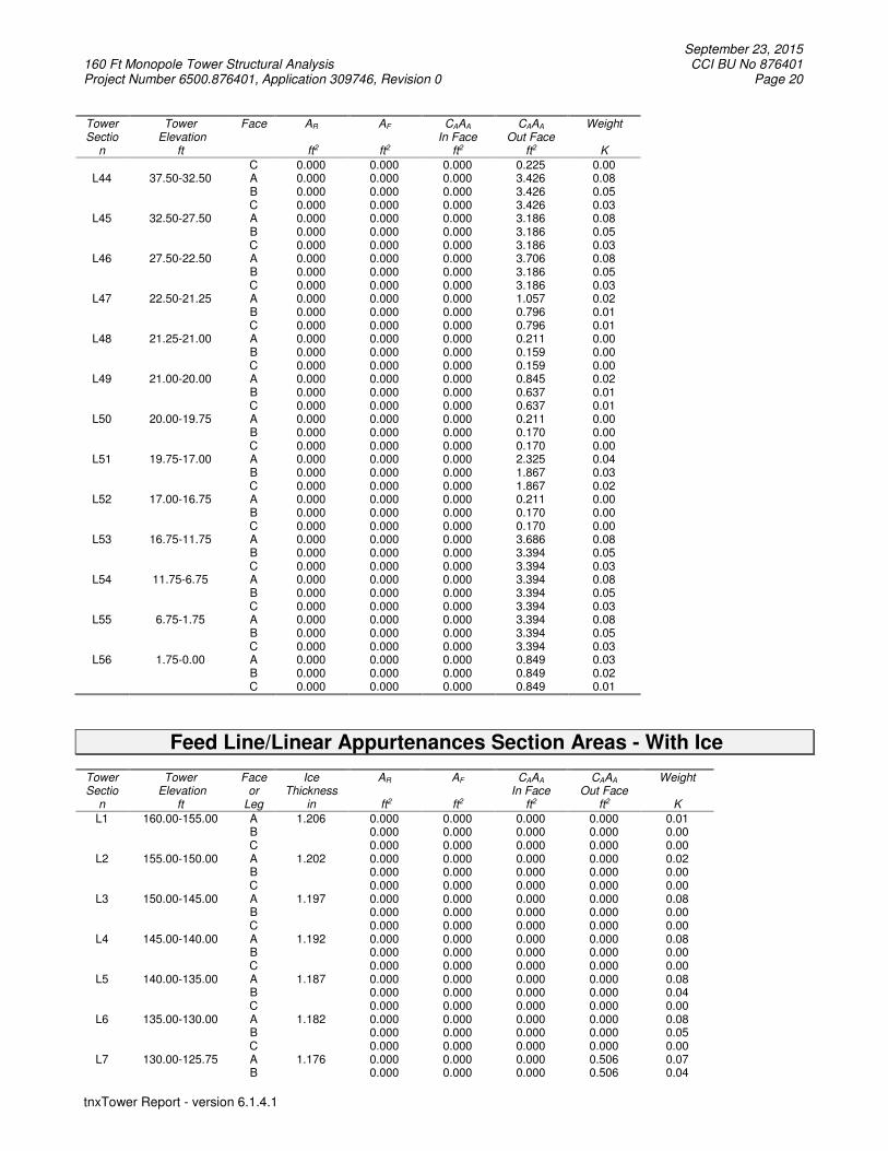
September 23, 2015 160 Ft Monopole Tower Structural Analysis CCI BU No 876401 Project Number 6500.876401, Application 309746, Revision 0 Page 20
tnxTower Report - version 6.1.4.1
Tower Sectio
n
Tower Elevation
ft
Face AR
ft2
AF
ft2
CAAA
In Face ft2
CAAA
Out Face ft2
Weight
K
C 0.000 0.000 0.000 0.225 0.00 L44 37.50-32.50 A
B C
0.000 0.000 0.000
0.000 0.000 0.000
0.000 0.000 0.000
3.426 3.426 3.426
0.08 0.05 0.03
L45 32.50-27.50 A B C
0.000 0.000 0.000
0.000 0.000 0.000
0.000 0.000 0.000
3.186 3.186 3.186
0.08 0.05 0.03
L46 27.50-22.50 A B C
0.000 0.000 0.000
0.000 0.000 0.000
0.000 0.000 0.000
3.706 3.186 3.186
0.08 0.05 0.03
L47 22.50-21.25 A B C
0.000 0.000 0.000
0.000 0.000 0.000
0.000 0.000 0.000
1.057 0.796 0.796
0.02 0.01 0.01
L48 21.25-21.00 A B C
0.000 0.000 0.000
0.000 0.000 0.000
0.000 0.000 0.000
0.211 0.159 0.159
0.00 0.00 0.00
L49 21.00-20.00 A B C
0.000 0.000 0.000
0.000 0.000 0.000
0.000 0.000 0.000
0.845 0.637 0.637
0.02 0.01 0.01
L50 20.00-19.75 A B C
0.000 0.000 0.000
0.000 0.000 0.000
0.000 0.000 0.000
0.211 0.170 0.170
0.00 0.00 0.00
L51 19.75-17.00 A B C
0.000 0.000 0.000
0.000 0.000 0.000
0.000 0.000 0.000
2.325 1.867 1.867
0.04 0.03 0.02
L52 17.00-16.75 A B C
0.000 0.000 0.000
0.000 0.000 0.000
0.000 0.000 0.000
0.211 0.170 0.170
0.00 0.00 0.00
L53 16.75-11.75 A B C
0.000 0.000 0.000
0.000 0.000 0.000
0.000 0.000 0.000
3.686 3.394 3.394
0.08 0.05 0.03
L54 11.75-6.75 A B C
0.000 0.000 0.000
0.000 0.000 0.000
0.000 0.000 0.000
3.394 3.394 3.394
0.08 0.05 0.03
L55 6.75-1.75 A B C
0.000 0.000 0.000
0.000 0.000 0.000
0.000 0.000 0.000
3.394 3.394 3.394
0.08 0.05 0.03
L56 1.75-0.00 A B C
0.000 0.000 0.000
0.000 0.000 0.000
0.000 0.000 0.000
0.849 0.849 0.849
0.03 0.02 0.01
Feed Line/Linear Appurtenances Section Areas - With Ice
Tower Sectio
n
Tower Elevation
ft
Face or
Leg
Ice Thickness
in
AR
ft2
AF
ft2
CAAA
In Face ft2
CAAA
Out Face ft2
Weight
K
L1 160.00-155.00 A B C
1.206 0.000 0.000 0.000
0.000 0.000 0.000
0.000 0.000 0.000
0.000 0.000 0.000
0.01 0.00 0.00
L2 155.00-150.00 A B C
1.202 0.000 0.000 0.000
0.000 0.000 0.000
0.000 0.000 0.000
0.000 0.000 0.000
0.02 0.00 0.00
L3 150.00-145.00 A B C
1.197 0.000 0.000 0.000
0.000 0.000 0.000
0.000 0.000 0.000
0.000 0.000 0.000
0.08 0.00 0.00
L4 145.00-140.00 A B C
1.192 0.000 0.000 0.000
0.000 0.000 0.000
0.000 0.000 0.000
0.000 0.000 0.000
0.08 0.00 0.00
L5 140.00-135.00 A B C
1.187 0.000 0.000 0.000
0.000 0.000 0.000
0.000 0.000 0.000
0.000 0.000 0.000
0.08 0.04 0.00
L6 135.00-130.00 A B C
1.182 0.000 0.000 0.000
0.000 0.000 0.000
0.000 0.000 0.000
0.000 0.000 0.000
0.08 0.05 0.00
L7 130.00-125.75 A B
1.176 0.000 0.000
0.000 0.000
0.000 0.000
0.506 0.506
0.07 0.04

September 23, 2015 160 Ft Monopole Tower Structural Analysis CCI BU No 876401 Project Number 6500.876401, Application 309746, Revision 0 Page 21
tnxTower Report - version 6.1.4.1
Tower Sectio
n
Tower Elevation
ft
Face or
Leg
Ice Thickness
in
AR
ft2
AF
ft2
CAAA
In Face ft2
CAAA
Out Face ft2
Weight
K
C 0.000 0.000 0.000 0.506 0.00 L8 125.75-125.50 A
B C
1.174 0.000 0.000 0.000
0.000 0.000 0.000
0.000 0.000 0.000
0.101 0.101 0.101
0.00 0.00 0.00
L9 125.50-119.12 A B C
1.170 0.000 0.000 0.000
0.000 0.000 0.000
0.000 0.000 0.000
2.574 2.574 2.574
0.10 0.06 0.02
L10 119.12-119.00 A B C
1.166 0.000 0.000 0.000
0.000 0.000 0.000
0.000 0.000 0.000
0.048 0.048 0.048
0.00 0.00 0.00
L11 119.00-118.75 A B C
1.166 0.000 0.000 0.000
0.000 0.000 0.000
0.000 0.000 0.000
0.101 0.101 0.101
0.00 0.00 0.00
L12 118.75-113.75 A B C
1.163 0.000 0.000 0.000
0.000 0.000 0.000
0.000 0.000 0.000
2.011 2.011 2.011
0.08 0.05 0.01
L13 113.75-108.75 A B C
1.157 0.000 0.000 0.000
0.000 0.000 0.000
0.000 0.000 0.000
2.006 2.006 2.006
0.08 0.05 0.01
L14 108.75-103.75 A B C
1.151 0.000 0.000 0.000
0.000 0.000 0.000
0.000 0.000 0.000
2.449 2.001 2.449
0.08 0.05 0.02
L15 103.75-103.00 A B C
1.147 0.000 0.000 0.000
0.000 0.000 0.000
0.000 0.000 0.000
0.568 0.300 0.568
0.01 0.01 0.00
L16 103.00-102.75 A B C
1.146 0.000 0.000 0.000
0.000 0.000 0.000
0.000 0.000 0.000
0.189 0.100 0.189
0.00 0.00 0.00
L17 102.75-100.21 A B C
1.144 0.000 0.000 0.000
0.000 0.000 0.000
0.000 0.000 0.000
1.923 1.726 1.923
0.04 0.03 0.01
L18 100.21-95.83 A B C
1.140 0.000 0.000 0.000
0.000 0.000 0.000
0.000 0.000 0.000
3.305 3.305 3.305
0.07 0.04 0.02
L19 95.83-94.83 A B C
1.136 0.000 0.000 0.000
0.000 0.000 0.000
0.000 0.000 0.000
0.816 0.816 0.816
0.02 0.01 0.01
L20 94.83-93.50 A B C
1.134 0.000 0.000 0.000
0.000 0.000 0.000
0.000 0.000 0.000
1.475 1.475 1.475
0.02 0.01 0.01
L21 93.50-93.25 A B C
1.133 0.000 0.000 0.000
0.000 0.000 0.000
0.000 0.000 0.000
0.277 0.277 0.277
0.00 0.00 0.00
L22 93.25-89.25 A B C
1.130 0.000 0.000 0.000
0.000 0.000 0.000
0.000 0.000 0.000
4.426 4.426 4.426
0.06 0.04 0.02
L23 89.25-89.00 A B C
1.127 0.000 0.000 0.000
0.000 0.000 0.000
0.000 0.000 0.000
0.276 0.276 0.276
0.00 0.00 0.00
L24 89.00-86.50 A B C
1.125 0.000 0.000 0.000
0.000 0.000 0.000
0.000 0.000 0.000
2.760 2.760 2.760
0.04 0.03 0.01
L25 86.50-86.25 A B C
1.122 0.000 0.000 0.000
0.000 0.000 0.000
0.000 0.000 0.000
0.276 0.276 0.276
0.00 0.00 0.00
L26 86.25-81.25 A B C
1.118 0.000 0.000 0.000
0.000 0.000 0.000
0.000 0.000 0.000
4.180 4.180 4.180
0.08 0.05 0.03
L27 81.25-76.25 A B C
1.110 0.000 0.000 0.000
0.000 0.000 0.000
0.000 0.000 0.000
3.895 3.895 3.895
0.08 0.05 0.03
L28 76.25-75.42 A B C
1.105 0.000 0.000 0.000
0.000 0.000 0.000
0.000 0.000 0.000
1.042 1.042 1.042
0.01 0.01 0.00
L29 75.42-75.17 A B C
1.104 0.000 0.000 0.000
0.000 0.000 0.000
0.000 0.000 0.000
0.313 0.313 0.313
0.00 0.00 0.00
L30 75.17-70.17 A B
1.099 0.000 0.000
0.000 0.000
0.000 0.000
6.241 6.241
0.08 0.05

September 23, 2015 160 Ft Monopole Tower Structural Analysis CCI BU No 876401 Project Number 6500.876401, Application 309746, Revision 0 Page 22
tnxTower Report - version 6.1.4.1
Tower Sectio
n
Tower Elevation
ft
Face or
Leg
Ice Thickness
in
AR
ft2
AF
ft2
CAAA
In Face ft2
CAAA
Out Face ft2
Weight
K
C 0.000 0.000 0.000 6.241 0.03 L31 70.17-65.17 A
B C
1.090 0.000 0.000 0.000
0.000 0.000 0.000
0.000 0.000 0.000
6.215 6.215 6.215
0.08 0.05 0.03
L32 65.17-60.17 A B C
1.080 0.000 0.000 0.000
0.000 0.000 0.000
0.000 0.000 0.000
6.187 6.187 6.187
0.08 0.05 0.03
L33 60.17-59.50 A B C
1.074 0.000 0.000 0.000
0.000 0.000 0.000
0.000 0.000 0.000
0.823 0.823 0.823
0.01 0.01 0.00
L34 59.50-59.25 A B C
1.073 0.000 0.000 0.000
0.000 0.000 0.000
0.000 0.000 0.000
0.308 0.308 0.308
0.00 0.00 0.00
L35 59.25-54.25 A B C
1.067 0.000 0.000 0.000
0.000 0.000 0.000
0.000 0.000 0.000
6.152 6.410 6.152
0.08 0.05 0.03
L36 54.25-53.00 A B C
1.060 0.000 0.000 0.000
0.000 0.000 0.000
0.000 0.000 0.000
1.533 1.962 1.533
0.02 0.01 0.01
L37 53.00-47.20 A B C
1.051 0.000 0.000 0.000
0.000 0.000 0.000
0.000 0.000 0.000
7.085 9.068 7.085
0.09 0.06 0.03
L38 47.20-46.20 A B C
1.043 0.000 0.000 0.000
0.000 0.000 0.000
0.000 0.000 0.000
1.222 1.222 1.222
0.02 0.01 0.01
L39 46.20-41.20 A B C
1.034 0.000 0.000 0.000
0.000 0.000 0.000
0.000 0.000 0.000
6.060 6.060 6.060
0.08 0.05 0.03
L40 41.20-39.33 A B C
1.024 0.000 0.000 0.000
0.000 0.000 0.000
0.000 0.000 0.000
2.824 2.824 2.824
0.03 0.02 0.01
L41 39.33-39.08 A B C
1.021 0.000 0.000 0.000
0.000 0.000 0.000
0.000 0.000 0.000
0.423 0.423 0.423
0.00 0.00 0.00
L42 39.08-37.75 A B C
1.018 0.000 0.000 0.000
0.000 0.000 0.000
0.000 0.000 0.000
2.255 2.255 2.255
0.02 0.01 0.01
L43 37.75-37.50 A B C
1.016 0.000 0.000 0.000
0.000 0.000 0.000
0.000 0.000 0.000
0.423 0.423 0.423
0.00 0.00 0.00
L44 37.50-32.50 A B C
1.007 0.000 0.000 0.000
0.000 0.000 0.000
0.000 0.000 0.000
6.430 6.430 6.430
0.08 0.05 0.03
L45 32.50-27.50 A B C
1.000 0.000 0.000 0.000
0.000 0.000 0.000
0.000 0.000 0.000
5.965 5.965 5.965
0.08 0.05 0.03
L46 27.50-22.50 A B C
1.000 0.000 0.000 0.000
0.000 0.000 0.000
0.000 0.000 0.000
6.903 5.965 5.965
0.08 0.05 0.03
L47 22.50-21.25 A B C
1.000 0.000 0.000 0.000
0.000 0.000 0.000
0.000 0.000 0.000
1.960 1.491 1.491
0.02 0.01 0.01
L48 21.25-21.00 A B C
1.000 0.000 0.000 0.000
0.000 0.000 0.000
0.000 0.000 0.000
0.392 0.298 0.298
0.00 0.00 0.00
L49 21.00-20.00 A B C
1.000 0.000 0.000 0.000
0.000 0.000 0.000
0.000 0.000 0.000
1.568 1.193 1.193
0.02 0.01 0.01
L50 20.00-19.75 A B C
1.000 0.000 0.000 0.000
0.000 0.000 0.000
0.000 0.000 0.000
0.392 0.309 0.309
0.00 0.00 0.00
L51 19.75-17.00 A B C
1.000 0.000 0.000 0.000
0.000 0.000 0.000
0.000 0.000 0.000
4.312 3.395 3.395
0.04 0.03 0.02
L52 17.00-16.75 A B C
1.000 0.000 0.000 0.000
0.000 0.000 0.000
0.000 0.000 0.000
0.392 0.309 0.309
0.00 0.00 0.00
L53 16.75-11.75 A B
1.000 0.000 0.000
0.000 0.000
0.000 0.000
6.757 6.173
0.08 0.05

September 23, 2015 160 Ft Monopole Tower Structural Analysis CCI BU No 876401 Project Number 6500.876401, Application 309746, Revision 0 Page 23
tnxTower Report - version 6.1.4.1
Tower Sectio
n
Tower Elevation
ft
Face or
Leg
Ice Thickness
in
AR
ft2
AF
ft2
CAAA
In Face ft2
CAAA
Out Face ft2
Weight
K
C 0.000 0.000 0.000 6.173 0.03 L54 11.75-6.75 A
B C
1.000 0.000 0.000 0.000
0.000 0.000 0.000
0.000 0.000 0.000
6.173 6.173 6.173
0.08 0.05 0.03
L55 6.75-1.75 A B C
1.000 0.000 0.000 0.000
0.000 0.000 0.000
0.000 0.000 0.000
6.173 6.173 6.173
0.08 0.05 0.03
L56 1.75-0.00 A B C
1.000 0.000 0.000 0.000
0.000 0.000 0.000
0.000 0.000 0.000
1.543 1.543 1.543
0.03 0.02 0.01
Feed Line Center of Pressure
Section Elevation
ft
CPX
in
CPZ
in
CPX
Ice in
CPZ
Ice in
L1 160.00-155.00 0.0000 0.0000 0.0000 0.0000 L2 155.00-150.00 0.0000 0.0000 0.0000 0.0000 L3 150.00-145.00 0.0000 0.0000 0.0000 0.0000 L4 145.00-140.00 0.0000 0.0000 0.0000 0.0000 L5 140.00-135.00 0.0000 0.0000 0.0000 0.0000 L6 135.00-130.00 0.0000 0.0000 0.0000 0.0000 L7 130.00-125.75 0.0000 0.0000 0.0000 0.0000 L8 125.75-125.50 0.0000 0.0000 0.0000 0.0000 L9 125.50-119.12 0.0000 0.0000 0.0000 0.0000
L10 119.12-119.00 0.0000 0.0000 0.0000 0.0000 L11 119.00-118.75 0.0000 0.0000 0.0000 0.0000 L12 118.75-113.75 0.0000 0.0000 0.0000 0.0000 L13 113.75-108.75 0.0000 0.0000 0.0000 0.0000 L14 108.75-103.75 -0.0422 -0.0244 -0.0707 -0.0408 L15 103.75-103.00 -0.1547 -0.0893 -0.2473 -0.1428 L16 103.00-102.75 -0.1548 -0.0894 -0.2477 -0.1430 L17 102.75-100.21 -0.0321 -0.0185 -0.0503 -0.0291 L18 100.21-95.83 0.0000 0.0000 0.0000 0.0000 L19 95.83-94.83 0.0000 0.0000 0.0000 0.0000 L20 94.83-93.50 0.0000 0.0000 0.0000 0.0000 L21 93.50-93.25 0.0000 0.0000 0.0000 0.0000 L22 93.25-89.25 0.0000 0.0000 0.0000 0.0000 L23 89.25-89.00 0.0000 0.0000 0.0000 0.0000 L24 89.00-86.50 0.0000 0.0000 0.0000 0.0000 L25 86.50-86.25 0.0000 0.0000 0.0000 0.0000 L26 86.25-81.25 0.0000 0.0000 0.0000 0.0000 L27 81.25-76.25 0.0000 0.0000 0.0000 0.0000 L28 76.25-75.42 0.0000 0.0000 0.0000 0.0000 L29 75.42-75.17 0.0000 0.0000 0.0000 0.0000 L30 75.17-70.17 0.0000 0.0000 0.0000 0.0000 L31 70.17-65.17 0.0000 0.0000 0.0000 0.0000 L32 65.17-60.17 0.0000 0.0000 0.0000 0.0000 L33 60.17-59.50 0.0000 0.0000 0.0000 0.0000 L34 59.50-59.25 0.0000 0.0000 0.0000 0.0000 L35 59.25-54.25 0.0205 0.0118 0.0306 0.0177 L36 54.25-53.00 0.1324 0.0764 0.1953 0.1127 L37 53.00-47.20 0.1334 0.0770 0.1971 0.1138 L38 47.20-46.20 0.0000 0.0000 0.0000 0.0000 L39 46.20-41.20 0.0000 0.0000 0.0000 0.0000 L40 41.20-39.33 0.0000 0.0000 0.0000 0.0000 L41 39.33-39.08 0.0000 0.0000 0.0000 0.0000 L42 39.08-37.75 0.0000 0.0000 0.0000 0.0000 L43 37.75-37.50 0.0000 0.0000 0.0000 0.0000 L44 37.50-32.50 0.0000 0.0000 0.0000 0.0000 L45 32.50-27.50 0.0000 0.0000 0.0000 0.0000 L46 27.50-22.50 0.0000 -0.1022 0.0000 -0.1381 L47 22.50-21.25 0.0000 -0.2007 0.0000 -0.2700 L48 21.25-21.00 0.0000 -0.2009 0.0000 -0.2705 L49 21.00-20.00 0.0000 -0.2012 0.0000 -0.2710

September 23, 2015 160 Ft Monopole Tower Structural Analysis CCI BU No 876401 Project Number 6500.876401, Application 309746, Revision 0 Page 24
tnxTower Report - version 6.1.4.1
Section Elevation
ft
CPX
in
CPZ
in
CPX
Ice in
CPZ
Ice in
L50 20.00-19.75 0.0000 -0.1589 0.0000 -0.2387 L51 19.75-17.00 0.0000 -0.1593 0.0000 -0.2396 L52 17.00-16.75 0.0000 -0.1597 0.0000 -0.2405 L53 16.75-11.75 0.0000 -0.0567 0.0000 -0.0864 L54 11.75-6.75 0.0000 0.0000 0.0000 0.0000 L55 6.75-1.75 0.0000 0.0000 0.0000 0.0000 L56 1.75-0.00 0.0000 0.0000 0.0000 0.0000
Discrete Tower Loads
Description Face or
Leg
Offset Type
Offsets: Horz
Lateral Vert
ft ft ft
Azimuth Adjustmen
t °
Placement
ft
CAAA Front
ft2
CAAA Side
ft2
Weight
K
***159*** APXVSPP18-C-A20 w/
Mount Pipe A From Leg 4.00
0.00 0.00
0.0000 159.00 No Ice 1/2'' Ice
1'' Ice 2'' Ice 4'' Ice
8.50 9.15 9.77
11.03 13.68
6.95 8.13 9.02
10.84 14.85
0.08 0.15 0.23 0.41 0.91
APXVSPP18-C-A20 w/ Mount Pipe
B From Leg 4.00 0.00 0.00
0.0000 159.00 No Ice 1/2'' Ice
1'' Ice 2'' Ice 4'' Ice
8.50 9.15 9.77
11.03 13.68
6.95 8.13 9.02
10.84 14.85
0.08 0.15 0.23 0.41 0.91
APXVSPP18-C-A20 w/ Mount Pipe
C From Leg 4.00 0.00 0.00
0.0000 159.00 No Ice 1/2'' Ice
1'' Ice 2'' Ice 4'' Ice
8.50 9.15 9.77
11.03 13.68
6.95 8.13 9.02
10.84 14.85
0.08 0.15 0.23 0.41 0.91
(3) 7' x 2'' STD Pipe A From Leg 4.00 0.00 0.00
0.0000 159.00 No Ice 1/2'' Ice
1'' Ice 2'' Ice 4'' Ice
1.66 2.39 2.83 3.71 5.58
1.66 2.39 2.83 3.71 5.58
0.03 0.04 0.06 0.10 0.27
(3) 7' x 2'' STD Pipe B From Leg 4.00 0.00 0.00
0.0000 159.00 No Ice 1/2'' Ice
1'' Ice 2'' Ice 4'' Ice
1.66 2.39 2.83 3.71 5.58
1.66 2.39 2.83 3.71 5.58
0.03 0.04 0.06 0.10 0.27
(3) 7' x 2'' STD Pipe C From Leg 4.00 0.00 0.00
0.0000 159.00 No Ice 1/2'' Ice
1'' Ice 2'' Ice 4'' Ice
1.66 2.39 2.83 3.71 5.58
1.66 2.39 2.83 3.71 5.58
0.03 0.04 0.06 0.10 0.27
LP 712-1 C None 0.0000 159.00 No Ice 1/2'' Ice
1'' Ice 2'' Ice 4'' Ice
24.53 29.94 35.35 46.17 67.81
24.53 29.94 35.35 46.17 67.81
1.34 1.65 1.96 2.58 3.82
***157*** 800MHz 2X50W RRH
W/FILTER A From Leg 1.00
0.00 0.00
0.0000 157.00 No Ice 1/2'' Ice
1'' Ice
2.40 2.61 2.83 3.30
2.25 2.46 2.68 3.13
0.06 0.09 0.11 0.17

September 23, 2015 160 Ft Monopole Tower Structural Analysis CCI BU No 876401 Project Number 6500.876401, Application 309746, Revision 0 Page 25
tnxTower Report - version 6.1.4.1
Description Face or
Leg
Offset Type
Offsets: Horz
Lateral Vert
ft ft ft
Azimuth Adjustmen
t °
Placement
ft
CAAA Front
ft2
CAAA Side
ft2
Weight
K
2'' Ice 4'' Ice
4.34 4.15 0.34
800MHz 2X50W RRH W/FILTER
B From Leg 1.00 0.00 0.00
0.0000 157.00 No Ice 1/2'' Ice
1'' Ice 2'' Ice 4'' Ice
2.40 2.61 2.83 3.30 4.34
2.25 2.46 2.68 3.13 4.15
0.06 0.09 0.11 0.17 0.34
800MHz 2X50W RRH W/FILTER
C From Leg 1.00 0.00 0.00
0.0000 157.00 No Ice 1/2'' Ice
1'' Ice 2'' Ice 4'' Ice
2.40 2.61 2.83 3.30 4.34
2.25 2.46 2.68 3.13 4.15
0.06 0.09 0.11 0.17 0.34
PCS 1900MHz 4x45W-65MHz
A From Leg 1.00 0.00 -3.00
0.0000 157.00 No Ice 1/2'' Ice
1'' Ice 2'' Ice 4'' Ice
2.71 2.95 3.20 3.72 4.86
2.61 2.85 3.09 3.61 4.74
0.06 0.08 0.11 0.17 0.35
PCS 1900MHz 4x45W-65MHz
B From Leg 1.00 0.00 -3.00
0.0000 157.00 No Ice 1/2'' Ice
1'' Ice 2'' Ice 4'' Ice
2.71 2.95 3.20 3.72 4.86
2.61 2.85 3.09 3.61 4.74
0.06 0.08 0.11 0.17 0.35
PCS 1900MHz 4x45W-65MHz
C From Leg 1.00 0.00 -3.00
0.0000 157.00 No Ice 1/2'' Ice
1'' Ice 2'' Ice 4'' Ice
2.71 2.95 3.20 3.72 4.86
2.61 2.85 3.09 3.61 4.74
0.06 0.08 0.11 0.17 0.35
SO 102-3 C None 0.0000 157.00 No Ice 1/2'' Ice
1'' Ice 2'' Ice 4'' Ice
3.00 3.48 3.96 4.92 6.84
3.00 3.48 3.96 4.92 6.84
0.08 0.11 0.14 0.20 0.32
***152*** (2) TME-RRUS-11 A From Leg 2.00
0.00 0.00
0.0000 152.00 No Ice 1/2'' Ice
1'' Ice 2'' Ice 4'' Ice
3.42 3.72 4.04 4.72 6.25
1.85 2.19 2.55 3.38 5.29
0.06 0.08 0.12 0.19 0.43
(2) TME-RRUS-11 B From Leg 2.00 0.00 0.00
0.0000 152.00 No Ice 1/2'' Ice
1'' Ice 2'' Ice 4'' Ice
3.42 3.72 4.04 4.72 6.25
1.85 2.19 2.55 3.38 5.29
0.06 0.08 0.12 0.19 0.43
(2) TME-RRUS-11 C From Leg 2.00 0.00 0.00
0.0000 152.00 No Ice 1/2'' Ice
1'' Ice 2'' Ice 4'' Ice
3.42 3.72 4.04 4.72 6.25
1.85 2.19 2.55 3.38 5.29
0.06 0.08 0.12 0.19 0.43
SO 102-3 C None 0.0000 152.00 No Ice 1/2'' Ice
1'' Ice 2'' Ice 4'' Ice
3.00 3.48 3.96 4.92 6.84
3.00 3.48 3.96 4.92 6.84
0.08 0.11 0.14 0.20 0.32
***150*** (2) 7770.00 w/ Mount Pipe A From Leg 4.00 0.0000 150.00 No Ice 6.12 4.25 0.06

September 23, 2015 160 Ft Monopole Tower Structural Analysis CCI BU No 876401 Project Number 6500.876401, Application 309746, Revision 0 Page 26
tnxTower Report - version 6.1.4.1
Description Face or
Leg
Offset Type
Offsets: Horz
Lateral Vert
ft ft ft
Azimuth Adjustmen
t °
Placement
ft
CAAA Front
ft2
CAAA Side
ft2
Weight
K
0.00 0.00
1/2'' Ice
1'' Ice 2'' Ice 4'' Ice
6.63 7.13 8.16
10.36
5.01 5.71 7.16
10.41
0.10 0.16 0.29 0.66
(2) 7770.00 w/ Mount Pipe B From Leg 4.00 0.00 0.00
0.0000 150.00 No Ice 1/2'' Ice
1'' Ice 2'' Ice 4'' Ice
6.12 6.63 7.13 8.16
10.36
4.25 5.01 5.71 7.16
10.41
0.06 0.10 0.16 0.29 0.66
(2) 7770.00 w/ Mount Pipe C From Leg 4.00 0.00 0.00
0.0000 150.00 No Ice 1/2'' Ice
1'' Ice 2'' Ice 4'' Ice
6.12 6.63 7.13 8.16
10.36
4.25 5.01 5.71 7.16
10.41
0.06 0.10 0.16 0.29 0.66
AM-X-CD-17-65-00T-RET w/ Mount Pipe
A From Leg 4.00 0.00 0.00
0.0000 150.00 No Ice 1/2'' Ice
1'' Ice 2'' Ice 4'' Ice
11.55 12.27 13.00 14.45 17.71
8.94 10.45 11.99 14.31 19.14
0.09 0.18 0.27 0.50 1.12
AM-X-CD-17-65-00T-RET w/ Mount Pipe
B From Leg 4.00 0.00 0.00
0.0000 150.00 No Ice 1/2'' Ice
1'' Ice 2'' Ice 4'' Ice
11.55 12.27 13.00 14.45 17.71
8.94 10.45 11.99 14.31 19.14
0.09 0.18 0.27 0.50 1.12
AM-X-CD-17-65-00T-RET w/ Mount Pipe
C From Leg 4.00 0.00 0.00
0.0000 150.00 No Ice 1/2'' Ice
1'' Ice 2'' Ice 4'' Ice
11.55 12.27 13.00 14.45 17.71
8.94 10.45 11.99 14.31 19.14
0.09 0.18 0.27 0.50 1.12
(2) LGP21401 A From Leg 4.00 0.00 0.00
0.0000 150.00 No Ice 1/2'' Ice
1'' Ice 2'' Ice 4'' Ice
1.29 1.45 1.61 1.97 2.79
0.23 0.31 0.40 0.61 1.12
0.01 0.02 0.03 0.05 0.14
(2) LGP21401 B From Leg 4.00 0.00 0.00
0.0000 150.00 No Ice 1/2'' Ice
1'' Ice 2'' Ice 4'' Ice
1.29 1.45 1.61 1.97 2.79
0.23 0.31 0.40 0.61 1.12
0.01 0.02 0.03 0.05 0.14
(2) LGP21401 C From Leg 4.00 0.00 0.00
0.0000 150.00 No Ice 1/2'' Ice
1'' Ice 2'' Ice 4'' Ice
1.29 1.45 1.61 1.97 2.79
0.23 0.31 0.40 0.61 1.12
0.01 0.02 0.03 0.05 0.14
(2) LGP21901 A From Leg 4.00 0.00 0.00
0.0000 150.00 No Ice 1/2'' Ice
1'' Ice 2'' Ice 4'' Ice
0.27 0.34 0.43 0.62 1.10
0.18 0.25 0.32 0.49 0.94
0.01 0.01 0.01 0.02 0.07
(2) LGP21901 B From Leg 4.00 0.00 0.00
0.0000 150.00 No Ice 1/2'' Ice
1'' Ice 2'' Ice 4'' Ice
0.27 0.34 0.43 0.62 1.10
0.18 0.25 0.32 0.49 0.94
0.01 0.01 0.01 0.02 0.07

September 23, 2015 160 Ft Monopole Tower Structural Analysis CCI BU No 876401 Project Number 6500.876401, Application 309746, Revision 0 Page 27
tnxTower Report - version 6.1.4.1
Description Face or
Leg
Offset Type
Offsets: Horz
Lateral Vert
ft ft ft
Azimuth Adjustmen
t °
Placement
ft
CAAA Front
ft2
CAAA Side
ft2
Weight
K
(2) LGP21901 C From Leg 4.00 0.00 0.00
0.0000 150.00 No Ice 1/2'' Ice
1'' Ice 2'' Ice 4'' Ice
0.27 0.34 0.43 0.62 1.10
0.18 0.25 0.32 0.49 0.94
0.01 0.01 0.01 0.02 0.07
DC6-48-60-18-8F B From Leg 4.00 0.00 0.00
0.0000 150.00 No Ice 1/2'' Ice
1'' Ice 2'' Ice 4'' Ice
1.47 1.67 1.88 2.33 3.38
1.47 1.67 1.88 2.33 3.38
0.02 0.04 0.06 0.11 0.24
LP 303-1 C None 0.0000 150.00 No Ice 1/2'' Ice
1'' Ice 2'' Ice 4'' Ice
14.66 18.87 23.08 31.50 48.34
14.66 18.87 23.08 31.50 48.34
1.25 1.48 1.71 2.18 3.10
***139*** APXV18-203219-C-A20 w/
Mount Pipe A From Leg 4.00
0.00 0.00
0.0000 139.00 No Ice 1/2'' Ice
1'' Ice 2'' Ice 4'' Ice
6.18 6.68 7.18 8.21
10.39
4.00 4.74 5.43 6.85
10.03
0.06 0.11 0.16 0.29 0.66
APXV18-203219-C-A20 w/ Mount Pipe
B From Leg 4.00 0.00 0.00
0.0000 139.00 No Ice 1/2'' Ice
1'' Ice 2'' Ice 4'' Ice
6.18 6.68 7.18 8.21
10.39
4.00 4.74 5.43 6.85
10.03
0.06 0.11 0.16 0.29 0.66
APXV18-203219-C-A20 w/ Mount Pipe
C From Leg 4.00 0.00 0.00
0.0000 139.00 No Ice 1/2'' Ice
1'' Ice 2'' Ice 4'' Ice
6.18 6.68 7.18 8.21
10.39
4.00 4.74 5.43 6.85
10.03
0.06 0.11 0.16 0.29 0.66
LNX-6512DS-VTM w/ Mount Pipe
A From Leg 4.00 0.00 0.00
0.0000 139.00 No Ice 1/2'' Ice
1'' Ice 2'' Ice 4'' Ice
5.85 6.31 6.77 7.74 9.80
4.55 5.23 5.91 7.34
10.46
0.05 0.10 0.15 0.28 0.65
LNX-6512DS-VTM w/ Mount Pipe
B From Leg 4.00 0.00 0.00
0.0000 139.00 No Ice 1/2'' Ice
1'' Ice 2'' Ice 4'' Ice
5.85 6.31 6.77 7.74 9.80
4.55 5.23 5.91 7.34
10.46
0.05 0.10 0.15 0.28 0.65
LNX-6512DS-VTM w/ Mount Pipe
C From Leg 4.00 0.00 0.00
0.0000 139.00 No Ice 1/2'' Ice
1'' Ice 2'' Ice 4'' Ice
5.85 6.31 6.77 7.74 9.80
4.55 5.23 5.91 7.34
10.46
0.05 0.10 0.15 0.28 0.65
TMAT7LA-11A A From Leg 4.00 0.00 0.00
0.0000 139.00 No Ice 1/2'' Ice
1'' Ice 2'' Ice 4'' Ice
0.75 0.87 1.00 1.29 1.96
0.40 0.49 0.59 0.81 1.36
0.02 0.03 0.04 0.06 0.13
TMAT7LA-11A B From Leg 4.00 0.00 0.00
0.0000 139.00 No Ice 1/2'' Ice
1'' Ice
0.75 0.87 1.00 1.29
0.40 0.49 0.59 0.81
0.02 0.03 0.04 0.06

September 23, 2015 160 Ft Monopole Tower Structural Analysis CCI BU No 876401 Project Number 6500.876401, Application 309746, Revision 0 Page 28
tnxTower Report - version 6.1.4.1
Description Face or
Leg
Offset Type
Offsets: Horz
Lateral Vert
ft ft ft
Azimuth Adjustmen
t °
Placement
ft
CAAA Front
ft2
CAAA Side
ft2
Weight
K
2'' Ice 4'' Ice
1.96 1.36 0.13
TMAT7LA-11A C From Leg 4.00 0.00 0.00
0.0000 139.00 No Ice 1/2'' Ice
1'' Ice 2'' Ice 4'' Ice
0.75 0.87 1.00 1.29 1.96
0.40 0.49 0.59 0.81 1.36
0.02 0.03 0.04 0.06 0.13
ATBT-BOTTOM-24V A From Leg 4.00 0.00 0.00
0.0000 139.00 No Ice 1/2'' Ice
1'' Ice 2'' Ice 4'' Ice
0.12 0.17 0.23 0.38 0.77
0.08 0.12 0.17 0.30 0.67
0.00 0.00 0.01 0.01 0.04
ATBT-BOTTOM-24V B From Leg 4.00 0.00 0.00
0.0000 139.00 No Ice 1/2'' Ice
1'' Ice 2'' Ice 4'' Ice
0.12 0.17 0.23 0.38 0.77
0.08 0.12 0.17 0.30 0.67
0.00 0.00 0.01 0.01 0.04
ATBT-BOTTOM-24V C From Leg 4.00 0.00 0.00
0.0000 139.00 No Ice 1/2'' Ice
1'' Ice 2'' Ice 4'' Ice
0.12 0.17 0.23 0.38 0.77
0.08 0.12 0.17 0.30 0.67
0.00 0.00 0.01 0.01 0.04
5' x 2'' STD Pipe A From Leg 4.00 0.00 0.00
0.0000 139.00 No Ice 1/2'' Ice
1'' Ice 2'' Ice 4'' Ice
1.19 1.50 1.81 2.46 3.92
1.19 1.50 1.81 2.46 3.92
0.02 0.03 0.04 0.08 0.20
5' x 2'' STD Pipe B From Leg 4.00 0.00 0.00
0.0000 139.00 No Ice 1/2'' Ice
1'' Ice 2'' Ice 4'' Ice
1.19 1.50 1.81 2.46 3.92
1.19 1.50 1.81 2.46 3.92
0.02 0.03 0.04 0.08 0.20
5' x 2'' STD Pipe C From Leg 4.00 0.00 0.00
0.0000 139.00 No Ice 1/2'' Ice
1'' Ice 2'' Ice 4'' Ice
1.19 1.50 1.81 2.46 3.92
1.19 1.50 1.81 2.46 3.92
0.02 0.03 0.04 0.08 0.20
TA 602-3 C None 0.0000 139.00 No Ice 1/2'' Ice
1'' Ice 2'' Ice 4'' Ice
11.59 15.44 19.29 26.99 42.39
11.59 15.44 19.29 26.99 42.39
0.77 0.99 1.21 1.64 2.50
***130*** (2) LNX-6514DS-A1M w/
Mount Pipe A From Leg 4.00
0.00 3.00
0.0000 127.00 No Ice 1/2'' Ice
1'' Ice 2'' Ice 4'' Ice
8.65 9.31 9.93
11.20 13.87
7.08 8.27 9.18
11.02 15.06
0.06 0.13 0.21 0.39 0.90
(2) LNX-6514DS-A1M w/ Mount Pipe
B From Leg 4.00 0.00 3.00
0.0000 127.00 No Ice 1/2'' Ice
1'' Ice 2'' Ice 4'' Ice
8.65 9.31 9.93
11.20 13.87
7.08 8.27 9.18
11.02 15.06
0.06 0.13 0.21 0.39 0.90
(2) LNX-6514DS-A1M w/ Mount Pipe
C From Leg 4.00 0.00
0.0000 127.00 No Ice 1/2''
8.65 9.31
7.08 8.27
0.06 0.13

September 23, 2015 160 Ft Monopole Tower Structural Analysis CCI BU No 876401 Project Number 6500.876401, Application 309746, Revision 0 Page 29
tnxTower Report - version 6.1.4.1
Description Face or
Leg
Offset Type
Offsets: Horz
Lateral Vert
ft ft ft
Azimuth Adjustmen
t °
Placement
ft
CAAA Front
ft2
CAAA Side
ft2
Weight
K
3.00 Ice 1'' Ice 2'' Ice 4'' Ice
9.93 11.20 13.87
9.18 11.02 15.06
0.21 0.39 0.90
(2) HBXX-6517DS-A2M w/ Mount Pipe
A From Leg 4.00 0.00 3.00
0.0000 127.00 No Ice 1/2'' Ice
1'' Ice 2'' Ice 4'' Ice
8.92 9.56
10.19 11.46 14.13
6.91 8.10 9.01
10.86 14.81
0.08 0.15 0.22 0.41 0.92
(2) HBXX-6517DS-A2M w/ Mount Pipe
B From Leg 4.00 0.00 3.00
0.0000 127.00 No Ice 1/2'' Ice
1'' Ice 2'' Ice 4'' Ice
8.92 9.56
10.19 11.46 14.13
6.91 8.10 9.01
10.86 14.81
0.08 0.15 0.22 0.41 0.92
(2) HBXX-6517DS-A2M w/ Mount Pipe
C From Leg 4.00 0.00 3.00
0.0000 127.00 No Ice 1/2'' Ice
1'' Ice 2'' Ice 4'' Ice
8.92 9.56
10.19 11.46 14.13
6.91 8.10 9.01
10.86 14.81
0.08 0.15 0.22 0.41 0.92
RRH2X40-07-U A From Leg 4.00 0.00 3.00
0.0000 127.00 No Ice 1/2'' Ice
1'' Ice 2'' Ice 4'' Ice
2.25 2.45 2.66 3.10 4.10
1.23 1.39 1.55 1.91 2.73
0.05 0.07 0.09 0.13 0.27
RRH2X40-07-U B From Leg 4.00 0.00 3.00
0.0000 127.00 No Ice 1/2'' Ice
1'' Ice 2'' Ice 4'' Ice
2.25 2.45 2.66 3.10 4.10
1.23 1.39 1.55 1.91 2.73
0.05 0.07 0.09 0.13 0.27
RRH2X40-07-U C From Leg 4.00 0.00 3.00
0.0000 127.00 No Ice 1/2'' Ice
1'' Ice 2'' Ice 4'' Ice
2.25 2.45 2.66 3.10 4.10
1.23 1.39 1.55 1.91 2.73
0.05 0.07 0.09 0.13 0.27
RRH2X60-AWS A From Leg 4.00 0.00 3.00
0.0000 127.00 No Ice 1/2'' Ice
1'' Ice 2'' Ice 4'' Ice
3.96 4.27 4.60 5.27 6.72
2.05 2.33 2.62 3.23 4.54
0.06 0.08 0.11 0.18 0.36
RRH2X60-AWS B From Leg 4.00 0.00 3.00
0.0000 127.00 No Ice 1/2'' Ice
1'' Ice 2'' Ice 4'' Ice
3.96 4.27 4.60 5.27 6.72
2.05 2.33 2.62 3.23 4.54
0.06 0.08 0.11 0.18 0.36
RRH2X60-AWS C From Leg 4.00 0.00 3.00
0.0000 127.00 No Ice 1/2'' Ice
1'' Ice 2'' Ice 4'' Ice
3.96 4.27 4.60 5.27 6.72
2.05 2.33 2.62 3.23 4.54
0.06 0.08 0.11 0.18 0.36
RRH2X60-PCS A From Leg 4.00 0.00 3.00
0.0000 127.00 No Ice 1/2'' Ice
1'' Ice 2'' Ice 4'' Ice
2.57 2.79 3.02 3.52 4.61
2.01 2.22 2.43 2.89 3.92
0.06 0.08 0.10 0.16 0.31
RRH2X60-PCS B From Leg 4.00 0.0000 127.00 No Ice 2.57 2.01 0.06

September 23, 2015 160 Ft Monopole Tower Structural Analysis CCI BU No 876401 Project Number 6500.876401, Application 309746, Revision 0 Page 30
tnxTower Report - version 6.1.4.1
Description Face or
Leg
Offset Type
Offsets: Horz
Lateral Vert
ft ft ft
Azimuth Adjustmen
t °
Placement
ft
CAAA Front
ft2
CAAA Side
ft2
Weight
K
0.00 3.00
1/2'' Ice
1'' Ice 2'' Ice 4'' Ice
2.79 3.02 3.52 4.61
2.22 2.43 2.89 3.92
0.08 0.10 0.16 0.31
RRH2X60-PCS C From Leg 4.00 0.00 3.00
0.0000 127.00 No Ice 1/2'' Ice
1'' Ice 2'' Ice 4'' Ice
2.57 2.79 3.02 3.52 4.61
2.01 2.22 2.43 2.89 3.92
0.06 0.08 0.10 0.16 0.31
DB-T1-6Z-8AB-0Z A From Leg 4.00 0.00 3.00
0.0000 127.00 No Ice 1/2'' Ice
1'' Ice 2'' Ice 4'' Ice
5.60 5.92 6.24 6.91 8.37
2.33 2.56 2.79 3.28 4.37
0.04 0.08 0.12 0.21 0.45
DB-T1-6Z-8AB-0Z C From Leg 4.00 0.00 3.00
0.0000 127.00 No Ice 1/2'' Ice
1'' Ice 2'' Ice 4'' Ice
5.60 5.92 6.24 6.91 8.37
2.33 2.56 2.79 3.28 4.37
0.04 0.08 0.12 0.21 0.45
LP 303-1 C None 0.0000 127.00 No Ice 1/2'' Ice
1'' Ice 2'' Ice 4'' Ice
14.66 18.87 23.08 31.50 48.34
14.66 18.87 23.08 31.50 48.34
1.25 1.48 1.71 2.18 3.10
***109*** DB589 C From Leg 4.00
0.00 5.00
0.0000 109.00 No Ice 1/2'' Ice
1'' Ice 2'' Ice 4'' Ice
2.13 3.00 3.76 4.82 7.04
2.13 3.00 3.76 4.82 7.04
0.01 0.03 0.05 0.11 0.30
SO 701-1 C From Leg 2.00 0.00 0.00
0.0000 109.00 No Ice 1/2'' Ice
1'' Ice 2'' Ice 4'' Ice
0.85 1.14 1.43 2.01 3.17
1.67 2.34 3.01 4.35 7.03
0.07 0.08 0.09 0.12 0.18
SO 201-1 C From Leg 0.50 0.00 0.00
0.0000 109.00 No Ice 1/2'' Ice
1'' Ice 2'' Ice 4'' Ice
2.96 4.10 5.24 7.52
12.08
2.11 2.93 3.75 5.39 8.67
0.10 0.12 0.14 0.18 0.26
***105*** (2) 800 10504 w/ Mount
Pipe A From Leg 4.00
0.00 0.00
0.0000 105.00 No Ice 1/2'' Ice
1'' Ice 2'' Ice 4'' Ice
3.59 4.01 4.42 5.34 7.38
3.18 3.91 4.58 5.98 8.98
0.04 0.07 0.11 0.21 0.51
(2) 800 10504 w/ Mount Pipe
B From Leg 4.00 0.00 0.00
0.0000 105.00 No Ice 1/2'' Ice
1'' Ice 2'' Ice 4'' Ice
3.59 4.01 4.42 5.34 7.38
3.18 3.91 4.58 5.98 8.98
0.04 0.07 0.11 0.21 0.51
(2) 800 10504 w/ Mount Pipe
C From Leg 4.00 0.00 0.00
0.0000 105.00 No Ice 1/2'' Ice
1'' Ice
3.59 4.01 4.42 5.34
3.18 3.91 4.58 5.98
0.04 0.07 0.11 0.21

September 23, 2015 160 Ft Monopole Tower Structural Analysis CCI BU No 876401 Project Number 6500.876401, Application 309746, Revision 0 Page 31
tnxTower Report - version 6.1.4.1
Description Face or
Leg
Offset Type
Offsets: Horz
Lateral Vert
ft ft ft
Azimuth Adjustmen
t °
Placement
ft
CAAA Front
ft2
CAAA Side
ft2
Weight
K
2'' Ice 4'' Ice
7.38 8.98 0.51
(2) 860 10025 A From Leg 4.00 0.00 0.00
0.0000 105.00 No Ice 1/2'' Ice
1'' Ice 2'' Ice 4'' Ice
0.16 0.23 0.30 0.48 0.93
0.14 0.20 0.27 0.44 0.88
0.00 0.00 0.01 0.01 0.05
(2) 860 10025 B From Leg 4.00 0.00 0.00
0.0000 105.00 No Ice 1/2'' Ice
1'' Ice 2'' Ice 4'' Ice
0.16 0.23 0.30 0.48 0.93
0.14 0.20 0.27 0.44 0.88
0.00 0.00 0.01 0.01 0.05
(2) 860 10025 C From Leg 4.00 0.00 0.00
0.0000 105.00 No Ice 1/2'' Ice
1'' Ice 2'' Ice 4'' Ice
0.16 0.23 0.30 0.48 0.93
0.14 0.20 0.27 0.44 0.88
0.00 0.00 0.01 0.01 0.05
SM 506-3 C None 0.0000 105.00 No Ice 1/2'' Ice
1'' Ice 2'' Ice 4'' Ice
35.47 50.60 64.53 93.59 151.71
35.47 50.60 64.53 93.59 151.71
1.74 2.35 0.98 1.39 2.20
Tower Pressures - No Ice
GH = 1.690
Section
Elevation
ft
z
ft
KZ
qz
psf
AG
ft2
F a c e
AF
ft2
AR
ft2
Aleg
ft2
Leg %
CAAA In
Face ft2
CAAA Out
Face ft2
L1 160.00-155.00
157.47 1.563 29 7.108 A B C
0.000 0.000 0.000
7.108 7.108 7.108
7.108 100.00 100.00 100.00
0.000 0.000 0.000
0.000 0.000 0.000
L2 155.00-150.00
152.47 1.548 29 7.575 A B C
0.000 0.000 0.000
7.575 7.575 7.575
7.575 100.00 100.00 100.00
0.000 0.000 0.000
0.000 0.000 0.000
L3 150.00-145.00
147.48 1.534 28 8.042 A B C
0.000 0.000 0.000
8.042 8.042 8.042
8.042 100.00 100.00 100.00
0.000 0.000 0.000
0.000 0.000 0.000
L4 145.00-140.00
142.48 1.519 28 8.509 A B C
0.000 0.000 0.000
8.509 8.509 8.509
8.509 100.00 100.00 100.00
0.000 0.000 0.000
0.000 0.000 0.000
L5 140.00-135.00
137.48 1.503 28 8.976 A B C
0.000 0.000 0.000
8.976 8.976 8.976
8.976 100.00 100.00 100.00
0.000 0.000 0.000
0.000 0.000 0.000
L6 135.00-130.00
132.48 1.488 28 9.442 A B C
0.000 0.000 0.000
9.442 9.442 9.442
9.442 100.00 100.00 100.00
0.000 0.000 0.000
0.000 0.000 0.000
L7 130.00-125.75
127.86 1.473 27 8.393 A B C
0.000 0.000 0.000
8.393 8.393 8.393
8.393 100.00 100.00 100.00
0.000 0.000 0.000
0.260 0.260 0.260
L8 125.75-125.50
125.62 1.465 27 0.504 A B C
0.000 0.000 0.000
0.504 0.504 0.504
0.504 100.00 100.00 100.00
0.000 0.000 0.000
0.052 0.052 0.052

September 23, 2015 160 Ft Monopole Tower Structural Analysis CCI BU No 876401 Project Number 6500.876401, Application 309746, Revision 0 Page 32
tnxTower Report - version 6.1.4.1
Section Elevation
ft
z
ft
KZ
qz
psf
AG
ft2
F a c e
AF
ft2
AR
ft2
Aleg
ft2
Leg %
CAAA In
Face ft2
CAAA Out
Face ft2
L9 125.50-119.12
122.28 1.454 27 13.263 A B C
0.000 0.000 0.000
13.263 13.263 13.263
13.263 100.00 100.00 100.00
0.000 0.000 0.000
1.327 1.327 1.327
L10 119.12-119.00
119.06 1.443 27 0.253 A B C
0.000 0.000 0.000
0.253 0.253 0.253
0.253 100.00 100.00 100.00
0.000 0.000 0.000
0.025 0.025 0.025
L11 119.00-118.75
118.87 1.442 27 0.528 A B C
0.000 0.000 0.000
0.528 0.528 0.528
0.528 100.00 100.00 100.00
0.000 0.000 0.000
0.052 0.052 0.052
L12 118.75-113.75
116.23 1.433 27 10.792 A B C
0.000 0.000 0.000
10.792 10.792 10.792
10.792 100.00 100.00 100.00
0.000 0.000 0.000
1.040 1.040 1.040
L13 113.75-108.75
111.23 1.415 26 11.250 A B C
0.000 0.000 0.000
11.250 11.250 11.250
11.250 100.00 100.00 100.00
0.000 0.000 0.000
1.040 1.040 1.040
L14 108.75-103.75
106.23 1.397 26 11.708 A B C
0.000 0.000 0.000
11.708 11.708 11.708
11.708 100.00 100.00 100.00
0.000 0.000 0.000
1.248 1.040 1.248
L15 103.75-103.00
103.37 1.386 26 1.796 A B C
0.000 0.000 0.000
1.796 1.796 1.796
1.796 100.00 100.00 100.00
0.000 0.000 0.000
0.281 0.156 0.281
L16 103.00-102.75
102.87 1.384 26 0.601 A B C
0.000 0.000 0.000
0.601 0.601 0.601
0.601 100.00 100.00 100.00
0.000 0.000 0.000
0.094 0.052 0.094
L17 102.75-100.21
101.47 1.378 25 6.175 A B C
0.000 0.000 0.000
6.175 6.175 6.175
6.175 100.00 100.00 100.00
0.000 0.000 0.000
0.952 0.861 0.952
L18 100.21-95.83
98.01 1.365 25 10.912 A B C
0.000 0.000 0.000
10.912 10.912 10.912
10.912 100.00 100.00 100.00
0.000 0.000 0.000
1.640 1.640 1.640
L19 95.83-94.83
95.33 1.354 25 2.501 A B C
0.000 0.000 0.000
2.501 2.501 2.501
2.501 100.00 100.00 100.00
0.000 0.000 0.000
0.403 0.403 0.403
L20 94.83-93.50
94.16 1.349 25 3.354 A B C
0.000 0.000 0.000
3.354 3.354 3.354
3.354 100.00 100.00 100.00
0.000 0.000 0.000
0.720 0.720 0.720
L21 93.50-93.25
93.37 1.346 25 0.634 A B C
0.000 0.000 0.000
0.634 0.634 0.634
0.634 100.00 100.00 100.00
0.000 0.000 0.000
0.135 0.135 0.135
L22 93.25-89.25
91.24 1.337 25 10.304 A B C
0.000 0.000 0.000
10.304 10.304 10.304
10.304 100.00 100.00 100.00
0.000 0.000 0.000
2.165 2.165 2.165
L23 89.25-89.00
89.12 1.328 25 0.654 A B C
0.000 0.000 0.000
0.654 0.654 0.654
0.654 100.00 100.00 100.00
0.000 0.000 0.000
0.135 0.135 0.135
L24 89.00-86.50
87.75 1.322 24 6.601 A B C
0.000 0.000 0.000
6.601 6.601 6.601
6.601 100.00 100.00 100.00
0.000 0.000 0.000
1.353 1.353 1.353
L25 86.50-86.25
86.37 1.316 24 0.666 A B C
0.000 0.000 0.000
0.666 0.666 0.666
0.666 100.00 100.00 100.00
0.000 0.000 0.000
0.135 0.135 0.135
L26 86.25-81.25
83.74 1.305 24 13.572 A B C
0.000 0.000 0.000
13.572 13.572 13.572
13.572 100.00 100.00 100.00
0.000 0.000 0.000
2.082 2.082 2.082
L27 81.25-76.25
78.74 1.282 24 14.034 A B C
0.000 0.000 0.000
14.034 14.034 14.034
14.034 100.00 100.00 100.00
0.000 0.000 0.000
1.961 1.961 1.961
L28 76.25-75.42
75.83 1.268 23 2.383 A B C
0.000 0.000 0.000
2.383 2.383 2.383
2.383 100.00 100.00 100.00
0.000 0.000 0.000
0.531 0.531 0.531
L29 75.42-75.17
75.29 1.266 23 0.718 A B C
0.000 0.000 0.000
0.718 0.718 0.718
0.718 100.00 100.00 100.00
0.000 0.000 0.000
0.159 0.159 0.159
L30 75.17-70.17
72.65 1.253 23 14.595 A B C
0.000 0.000 0.000
14.595 14.595 14.595
14.595 100.00 100.00 100.00
0.000 0.000 0.000
3.186 3.186 3.186
L31 70.17-65.17
67.65 1.228 23 15.057 A B
0.000 0.000
15.057 15.057
15.057 100.00 100.00
0.000 0.000
3.186 3.186

September 23, 2015 160 Ft Monopole Tower Structural Analysis CCI BU No 876401 Project Number 6500.876401, Application 309746, Revision 0 Page 33
tnxTower Report - version 6.1.4.1
Section Elevation
ft
z
ft
KZ
qz
psf
AG
ft2
F a c e
AF
ft2
AR
ft2
Aleg
ft2
Leg %
CAAA In
Face ft2
CAAA Out
Face ft2
C 0.000 15.057 100.00 0.000 3.186 L32 65.17-
60.17 62.65 1.201 22 15.518 A
B C
0.000 0.000 0.000
15.518 15.518 15.518
15.518 100.00 100.00 100.00
0.000 0.000 0.000
3.186 3.186 3.186
L33 60.17-59.50
59.83 1.185 22 2.105 A B C
0.000 0.000 0.000
2.105 2.105 2.105
2.105 100.00 100.00 100.00
0.000 0.000 0.000
0.425 0.425 0.425
L34 59.50-59.25
59.37 1.183 22 0.791 A B C
0.000 0.000 0.000
0.791 0.791 0.791
0.791 100.00 100.00 100.00
0.000 0.000 0.000
0.159 0.159 0.159
L35 59.25-54.25
56.74 1.167 22 16.064 A B C
0.000 0.000 0.000
16.064 16.064 16.064
16.064 100.00 100.00 100.00
0.000 0.000 0.000
3.186 3.311 3.186
L36 54.25-53.00
53.62 1.149 21 4.088 A B C
0.000 0.000 0.000
4.088 4.088 4.088
4.088 100.00 100.00 100.00
0.000 0.000 0.000
0.796 1.005 0.796
L37 53.00-47.20
50.08 1.127 21 19.347 A B C
0.000 0.000 0.000
19.347 19.347 19.347
19.347 100.00 100.00 100.00
0.000 0.000 0.000
3.695 4.662 3.695
L38 47.20-46.20
46.70 1.104 20 3.346 A B C
0.000 0.000 0.000
3.346 3.346 3.346
3.346 100.00 100.00 100.00
0.000 0.000 0.000
0.637 0.637 0.637
L39 46.20-41.20
43.69 1.083 20 17.008 A B C
0.000 0.000 0.000
17.008 17.008 17.008
17.008 100.00 100.00 100.00
0.000 0.000 0.000
3.186 3.186 3.186
L40 41.20-39.33
40.26 1.058 20 6.469 A B C
0.000 0.000 0.000
6.469 6.469 6.469
6.469 100.00 100.00 100.00
0.000 0.000 0.000
1.496 1.496 1.496
L41 39.33-39.08
39.21 1.05 19 0.871 A B C
0.000 0.000 0.000
0.871 0.871 0.871
0.871 100.00 100.00 100.00
0.000 0.000 0.000
0.225 0.225 0.225
L42 39.08-37.75
38.42 1.044 19 4.664 A B C
0.000 0.000 0.000
4.664 4.664 4.664
4.664 100.00 100.00 100.00
0.000 0.000 0.000
1.199 1.199 1.199
L43 37.75-37.50
37.62 1.038 19 0.878 A B C
0.000 0.000 0.000
0.878 0.878 0.878
0.878 100.00 100.00 100.00
0.000 0.000 0.000
0.225 0.225 0.225
L44 37.50-32.50
34.99 1.017 19 17.811 A B C
0.000 0.000 0.000
17.811 17.811 17.811
17.811 100.00 100.00 100.00
0.000 0.000 0.000
3.426 3.426 3.426
L45 32.50-27.50
29.99 1 18 18.273 A B C
0.000 0.000 0.000
18.273 18.273 18.273
18.273 100.00 100.00 100.00
0.000 0.000 0.000
3.186 3.186 3.186
L46 27.50-22.50
24.99 1 18 18.734 A B C
0.000 0.000 0.000
18.734 18.734 18.734
18.734 100.00 100.00 100.00
0.000 0.000 0.000
3.706 3.186 3.186
L47 22.50-21.25
21.87 1 18 4.756 A B C
0.000 0.000 0.000
4.756 4.756 4.756
4.756 100.00 100.00 100.00
0.000 0.000 0.000
1.057 0.796 0.796
L48 21.25-21.00
21.12 1 18 0.955 A B C
0.000 0.000 0.000
0.955 0.955 0.955
0.955 100.00 100.00 100.00
0.000 0.000 0.000
0.211 0.159 0.159
L49 21.00-20.00
20.50 1 18 3.830 A B C
0.000 0.000 0.000
3.830 3.830 3.830
3.830 100.00 100.00 100.00
0.000 0.000 0.000
0.845 0.637 0.637
L50 20.00-19.75
19.87 1 18 0.960 A B C
0.000 0.000 0.000
0.960 0.960 0.960
0.960 100.00 100.00 100.00
0.000 0.000 0.000
0.211 0.170 0.170
L51 19.75-17.00
18.37 1 18 10.640 A B C
0.000 0.000 0.000
10.640 10.640 10.640
10.640 100.00 100.00 100.00
0.000 0.000 0.000
2.325 1.867 1.867
L52 17.00-16.75
16.87 1 18 0.974 A B C
0.000 0.000 0.000
0.974 0.974 0.974
0.974 100.00 100.00 100.00
0.000 0.000 0.000
0.211 0.170 0.170
L53 16.75-11.75
14.24 1 18 19.726 A B C
0.000 0.000 0.000
19.726 19.726 19.726
19.726 100.00 100.00 100.00
0.000 0.000 0.000
3.686 3.394 3.394
L54 11.75- 9.24 1 18 20.188 A 0.000 20.188 20.188 100.00 0.000 3.394

September 23, 2015 160 Ft Monopole Tower Structural Analysis CCI BU No 876401 Project Number 6500.876401, Application 309746, Revision 0 Page 34
tnxTower Report - version 6.1.4.1
Section Elevation
ft
z
ft
KZ
qz
psf
AG
ft2
F a c e
AF
ft2
AR
ft2
Aleg
ft2
Leg %
CAAA In
Face ft2
CAAA Out
Face ft2
6.75 B C
0.000 0.000
20.188 20.188
100.00 100.00
0.000 0.000
3.394 3.394
L55 6.75-1.75 4.24 1 18 20.649 A B C
0.000 0.000 0.000
20.649 20.649 20.649
20.649 100.00 100.00 100.00
0.000 0.000 0.000
3.394 3.394 3.394
L56 1.75-0.00 0.87 1 18 7.336 A B C
0.000 0.000 0.000
7.336 7.336 7.336
7.336 100.00 100.00 100.00
0.000 0.000 0.000
0.849 0.849 0.849
Tower Pressure - With Ice
GH = 1.690
Section
Elevation
ft
z
ft
KZ
qz
psf
tZ
in
AG
ft2
F a c e
AF
ft2
AR
ft2
Aleg
ft2
Leg %
CAAA In
Face ft2
CAAA Out
Face ft2
L1 160.00-155.00
157.47 1.563 6 1.2063 8.114 A B C
0.000 0.000 0.000
8.114 8.114 8.114
8.114 100.00 100.00 100.00
0.000 0.000 0.000
0.000 0.000 0.000
L2 155.00-150.00
152.47 1.548 6 1.2016 8.577 A B C
0.000 0.000 0.000
8.577 8.577 8.577
8.577 100.00 100.00 100.00
0.000 0.000 0.000
0.000 0.000 0.000
L3 150.00-145.00
147.48 1.534 6 1.1968 9.039 A B C
0.000 0.000 0.000
9.039 9.039 9.039
9.039 100.00 100.00 100.00
0.000 0.000 0.000
0.000 0.000 0.000
L4 145.00-140.00
142.48 1.519 5 1.1919 9.502 A B C
0.000 0.000 0.000
9.502 9.502 9.502
9.502 100.00 100.00 100.00
0.000 0.000 0.000
0.000 0.000 0.000
L5 140.00-135.00
137.48 1.503 5 1.1868 9.965 A B C
0.000 0.000 0.000
9.965 9.965 9.965
9.965 100.00 100.00 100.00
0.000 0.000 0.000
0.000 0.000 0.000
L6 135.00-130.00
132.48 1.488 5 1.1815 10.427 A B C
0.000 0.000 0.000
10.427 10.427 10.427
10.427 100.00 100.00 100.00
0.000 0.000 0.000
0.000 0.000 0.000
L7 130.00-125.75
127.86 1.473 5 1.1765 9.226 A B C
0.000 0.000 0.000
9.226 9.226 9.226
9.226 100.00 100.00 100.00
0.000 0.000 0.000
0.506 0.506 0.506
L8 125.75-125.50
125.62 1.465 5 1.1740 0.553 A B C
0.000 0.000 0.000
0.553 0.553 0.553
0.553 100.00 100.00 100.00
0.000 0.000 0.000
0.101 0.101 0.101
L9 125.50-119.12
122.28 1.454 5 1.1702 14.507 A B C
0.000 0.000 0.000
14.507 14.507 14.507
14.507 100.00 100.00 100.00
0.000 0.000 0.000
2.574 2.574 2.574
L10 119.12-119.00
119.06 1.443 5 1.1665 0.276 A B C
0.000 0.000 0.000
0.276 0.276 0.276
0.276 100.00 100.00 100.00
0.000 0.000 0.000
0.048 0.048 0.048
L11 119.00-118.75
118.87 1.442 5 1.1662 0.576 A B C
0.000 0.000 0.000
0.576 0.576 0.576
0.576 100.00 100.00 100.00
0.000 0.000 0.000
0.101 0.101 0.101
L12 118.75-113.75
116.23 1.433 5 1.1631 11.761 A B C
0.000 0.000 0.000
11.761 11.761 11.761
11.761 100.00 100.00 100.00
0.000 0.000 0.000
2.011 2.011 2.011
L13 113.75-108.75
111.23 1.415 5 1.1570 12.214 A B C
0.000 0.000 0.000
12.214 12.214 12.214
12.214 100.00 100.00 100.00
0.000 0.000 0.000
2.006 2.006 2.006
L14 108.75-103.75
106.23 1.397 5 1.1506 12.667 A B C
0.000 0.000 0.000
12.667 12.667 12.667
12.667 100.00 100.00 100.00
0.000 0.000 0.000
2.449 2.001 2.449
L15 103.75-103.00
103.37 1.386 5 1.1469 1.939 A B C
0.000 0.000 0.000
1.939 1.939 1.939
1.939 100.00 100.00 100.00
0.000 0.000 0.000
0.568 0.300 0.568
L16 103.00-102.75
102.87 1.384 5 1.1462 0.649 A B C
0.000 0.000 0.000
0.649 0.649 0.649
0.649 100.00 100.00 100.00
0.000 0.000 0.000
0.189 0.100 0.189

September 23, 2015 160 Ft Monopole Tower Structural Analysis CCI BU No 876401 Project Number 6500.876401, Application 309746, Revision 0 Page 35
tnxTower Report - version 6.1.4.1
Section Elevation
ft
z
ft
KZ
qz
psf
tZ
in
AG
ft2
F a c e
AF
ft2
AR
ft2
Aleg
ft2
Leg %
CAAA In
Face ft2
CAAA Out
Face ft2
L17 102.75-100.21
101.47 1.378 5 1.1443 6.659 A B C
0.000 0.000 0.000
6.659 6.659 6.659
6.659 100.00 100.00 100.00
0.000 0.000 0.000
1.923 1.726 1.923
L18 100.21-95.83
98.01 1.365 5 1.1395 11.743 A B C
0.000 0.000 0.000
11.743 11.743 11.743
11.743 100.00 100.00 100.00
0.000 0.000 0.000
3.305 3.305 3.305
L19 95.83-94.83
95.33 1.354 5 1.1358 2.691 A B C
0.000 0.000 0.000
2.691 2.691 2.691
2.691 100.00 100.00 100.00
0.000 0.000 0.000
0.816 0.816 0.816
L20 94.83-93.50
94.16 1.349 5 1.1341 3.606 A B C
0.000 0.000 0.000
3.606 3.606 3.606
3.606 100.00 100.00 100.00
0.000 0.000 0.000
1.475 1.475 1.475
L21 93.50-93.25
93.37 1.346 5 1.1329 0.681 A B C
0.000 0.000 0.000
0.681 0.681 0.681
0.681 100.00 100.00 100.00
0.000 0.000 0.000
0.277 0.277 0.277
L22 93.25-89.25
91.24 1.337 5 1.1298 11.057 A B C
0.000 0.000 0.000
11.057 11.057 11.057
11.057 100.00 100.00 100.00
0.000 0.000 0.000
4.426 4.426 4.426
L23 89.25-89.00
89.12 1.328 5 1.1266 0.701 A B C
0.000 0.000 0.000
0.701 0.701 0.701
0.701 100.00 100.00 100.00
0.000 0.000 0.000
0.276 0.276 0.276
L24 89.00-86.50
87.75 1.322 5 1.1245 7.070 A B C
0.000 0.000 0.000
7.070 7.070 7.070
7.070 100.00 100.00 100.00
0.000 0.000 0.000
2.760 2.760 2.760
L25 86.50-86.25
86.37 1.316 5 1.1224 0.713 A B C
0.000 0.000 0.000
0.713 0.713 0.713
0.713 100.00 100.00 100.00
0.000 0.000 0.000
0.276 0.276 0.276
L26 86.25-81.25
83.74 1.305 5 1.1182 14.504 A B C
0.000 0.000 0.000
14.504 14.504 14.504
14.504 100.00 100.00 100.00
0.000 0.000 0.000
4.180 4.180 4.180
L27 81.25-76.25
78.74 1.282 5 1.1100 14.959 A B C
0.000 0.000 0.000
14.959 14.959 14.959
14.959 100.00 100.00 100.00
0.000 0.000 0.000
3.895 3.895 3.895
L28 76.25-75.42
75.83 1.268 5 1.1050 2.536 A B C
0.000 0.000 0.000
2.536 2.536 2.536
2.536 100.00 100.00 100.00
0.000 0.000 0.000
1.042 1.042 1.042
L29 75.42-75.17
75.29 1.266 5 1.1040 0.764 A B C
0.000 0.000 0.000
0.764 0.764 0.764
0.764 100.00 100.00 100.00
0.000 0.000 0.000
0.313 0.313 0.313
L30 75.17-70.17
72.65 1.253 5 1.0993 15.511 A B C
0.000 0.000 0.000
15.511 15.511 15.511
15.511 100.00 100.00 100.00
0.000 0.000 0.000
6.241 6.241 6.241
L31 70.17-65.17
67.65 1.228 4 1.0900 15.965 A B C
0.000 0.000 0.000
15.965 15.965 15.965
15.965 100.00 100.00 100.00
0.000 0.000 0.000
6.215 6.215 6.215
L32 65.17-60.17
62.65 1.201 4 1.0800 16.418 A B C
0.000 0.000 0.000
16.418 16.418 16.418
16.418 100.00 100.00 100.00
0.000 0.000 0.000
6.187 6.187 6.187
L33 60.17-59.50
59.83 1.185 4 1.0740 2.224 A B C
0.000 0.000 0.000
2.224 2.224 2.224
2.224 100.00 100.00 100.00
0.000 0.000 0.000
0.823 0.823 0.823
L34 59.50-59.25
59.37 1.183 4 1.0730 0.836 A B C
0.000 0.000 0.000
0.836 0.836 0.836
0.836 100.00 100.00 100.00
0.000 0.000 0.000
0.308 0.308 0.308
L35 59.25-54.25
56.74 1.167 4 1.0672 16.954 A B C
0.000 0.000 0.000
16.954 16.954 16.954
16.954 100.00 100.00 100.00
0.000 0.000 0.000
6.152 6.410 6.152
L36 54.25-53.00
53.62 1.149 4 1.0600 4.309 A B C
0.000 0.000 0.000
4.309 4.309 4.309
4.309 100.00 100.00 100.00
0.000 0.000 0.000
1.533 1.962 1.533
L37 53.00-47.20
50.08 1.127 4 1.0513 20.363 A B C
0.000 0.000 0.000
20.363 20.363 20.363
20.363 100.00 100.00 100.00
0.000 0.000 0.000
7.085 9.068 7.085
L38 47.20-46.20
46.70 1.104 4 1.0425 3.522 A B C
0.000 0.000 0.000
3.522 3.522 3.522
3.522 100.00 100.00 100.00
0.000 0.000 0.000
1.222 1.222 1.222
L39 46.20-41.20
43.69 1.083 4 1.0342 17.870 A B
0.000 0.000
17.870 17.870
17.870 100.00 100.00
0.000 0.000
6.060 6.060
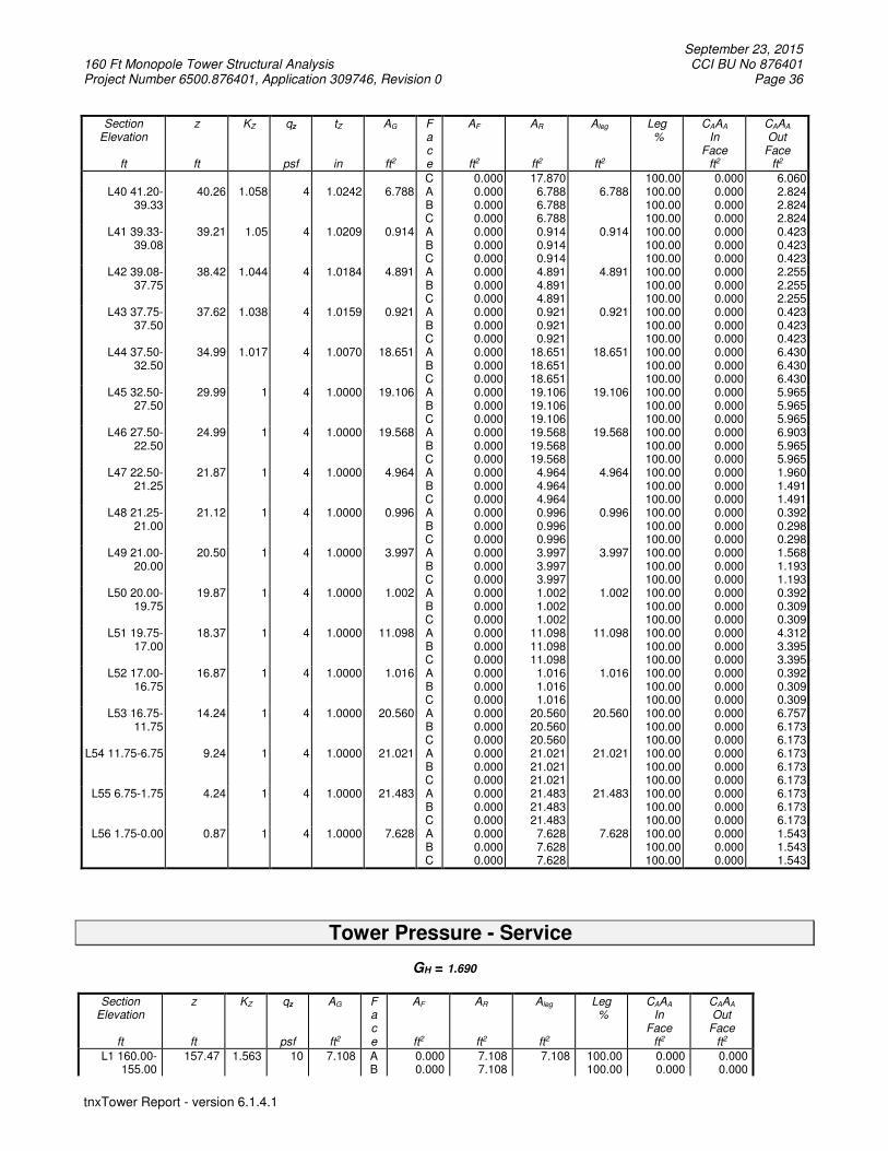
September 23, 2015 160 Ft Monopole Tower Structural Analysis CCI BU No 876401 Project Number 6500.876401, Application 309746, Revision 0 Page 36
tnxTower Report - version 6.1.4.1
Section Elevation
ft
z
ft
KZ
qz
psf
tZ
in
AG
ft2
F a c e
AF
ft2
AR
ft2
Aleg
ft2
Leg %
CAAA In
Face ft2
CAAA Out
Face ft2
C 0.000 17.870 100.00 0.000 6.060 L40 41.20-
39.33 40.26 1.058 4 1.0242 6.788 A
B C
0.000 0.000 0.000
6.788 6.788 6.788
6.788 100.00 100.00 100.00
0.000 0.000 0.000
2.824 2.824 2.824
L41 39.33-39.08
39.21 1.05 4 1.0209 0.914 A B C
0.000 0.000 0.000
0.914 0.914 0.914
0.914 100.00 100.00 100.00
0.000 0.000 0.000
0.423 0.423 0.423
L42 39.08-37.75
38.42 1.044 4 1.0184 4.891 A B C
0.000 0.000 0.000
4.891 4.891 4.891
4.891 100.00 100.00 100.00
0.000 0.000 0.000
2.255 2.255 2.255
L43 37.75-37.50
37.62 1.038 4 1.0159 0.921 A B C
0.000 0.000 0.000
0.921 0.921 0.921
0.921 100.00 100.00 100.00
0.000 0.000 0.000
0.423 0.423 0.423
L44 37.50-32.50
34.99 1.017 4 1.0070 18.651 A B C
0.000 0.000 0.000
18.651 18.651 18.651
18.651 100.00 100.00 100.00
0.000 0.000 0.000
6.430 6.430 6.430
L45 32.50-27.50
29.99 1 4 1.0000 19.106 A B C
0.000 0.000 0.000
19.106 19.106 19.106
19.106 100.00 100.00 100.00
0.000 0.000 0.000
5.965 5.965 5.965
L46 27.50-22.50
24.99 1 4 1.0000 19.568 A B C
0.000 0.000 0.000
19.568 19.568 19.568
19.568 100.00 100.00 100.00
0.000 0.000 0.000
6.903 5.965 5.965
L47 22.50-21.25
21.87 1 4 1.0000 4.964 A B C
0.000 0.000 0.000
4.964 4.964 4.964
4.964 100.00 100.00 100.00
0.000 0.000 0.000
1.960 1.491 1.491
L48 21.25-21.00
21.12 1 4 1.0000 0.996 A B C
0.000 0.000 0.000
0.996 0.996 0.996
0.996 100.00 100.00 100.00
0.000 0.000 0.000
0.392 0.298 0.298
L49 21.00-20.00
20.50 1 4 1.0000 3.997 A B C
0.000 0.000 0.000
3.997 3.997 3.997
3.997 100.00 100.00 100.00
0.000 0.000 0.000
1.568 1.193 1.193
L50 20.00-19.75
19.87 1 4 1.0000 1.002 A B C
0.000 0.000 0.000
1.002 1.002 1.002
1.002 100.00 100.00 100.00
0.000 0.000 0.000
0.392 0.309 0.309
L51 19.75-17.00
18.37 1 4 1.0000 11.098 A B C
0.000 0.000 0.000
11.098 11.098 11.098
11.098 100.00 100.00 100.00
0.000 0.000 0.000
4.312 3.395 3.395
L52 17.00-16.75
16.87 1 4 1.0000 1.016 A B C
0.000 0.000 0.000
1.016 1.016 1.016
1.016 100.00 100.00 100.00
0.000 0.000 0.000
0.392 0.309 0.309
L53 16.75-11.75
14.24 1 4 1.0000 20.560 A B C
0.000 0.000 0.000
20.560 20.560 20.560
20.560 100.00 100.00 100.00
0.000 0.000 0.000
6.757 6.173 6.173
L54 11.75-6.75 9.24 1 4 1.0000 21.021 A B C
0.000 0.000 0.000
21.021 21.021 21.021
21.021 100.00 100.00 100.00
0.000 0.000 0.000
6.173 6.173 6.173
L55 6.75-1.75 4.24 1 4 1.0000 21.483 A B C
0.000 0.000 0.000
21.483 21.483 21.483
21.483 100.00 100.00 100.00
0.000 0.000 0.000
6.173 6.173 6.173
L56 1.75-0.00 0.87 1 4 1.0000 7.628 A B C
0.000 0.000 0.000
7.628 7.628 7.628
7.628 100.00 100.00 100.00
0.000 0.000 0.000
1.543 1.543 1.543
Tower Pressure - Service
GH = 1.690
Section
Elevation
ft
z
ft
KZ
qz
psf
AG
ft2
F a c e
AF
ft2
AR
ft2
Aleg
ft2
Leg %
CAAA In
Face ft2
CAAA Out
Face ft2
L1 160.00-155.00
157.47 1.563 10 7.108 A B
0.000 0.000
7.108 7.108
7.108 100.00 100.00
0.000 0.000
0.000 0.000

September 23, 2015 160 Ft Monopole Tower Structural Analysis CCI BU No 876401 Project Number 6500.876401, Application 309746, Revision 0 Page 37
tnxTower Report - version 6.1.4.1
Section Elevation
ft
z
ft
KZ
qz
psf
AG
ft2
F a c e
AF
ft2
AR
ft2
Aleg
ft2
Leg %
CAAA In
Face ft2
CAAA Out
Face ft2
C 0.000 7.108 100.00 0.000 0.000 L2 155.00-
150.00 152.47 1.548 10 7.575 A
B C
0.000 0.000 0.000
7.575 7.575 7.575
7.575 100.00 100.00 100.00
0.000 0.000 0.000
0.000 0.000 0.000
L3 150.00-145.00
147.48 1.534 10 8.042 A B C
0.000 0.000 0.000
8.042 8.042 8.042
8.042 100.00 100.00 100.00
0.000 0.000 0.000
0.000 0.000 0.000
L4 145.00-140.00
142.48 1.519 10 8.509 A B C
0.000 0.000 0.000
8.509 8.509 8.509
8.509 100.00 100.00 100.00
0.000 0.000 0.000
0.000 0.000 0.000
L5 140.00-135.00
137.48 1.503 10 8.976 A B C
0.000 0.000 0.000
8.976 8.976 8.976
8.976 100.00 100.00 100.00
0.000 0.000 0.000
0.000 0.000 0.000
L6 135.00-130.00
132.48 1.488 10 9.442 A B C
0.000 0.000 0.000
9.442 9.442 9.442
9.442 100.00 100.00 100.00
0.000 0.000 0.000
0.000 0.000 0.000
L7 130.00-125.75
127.86 1.473 9 8.393 A B C
0.000 0.000 0.000
8.393 8.393 8.393
8.393 100.00 100.00 100.00
0.000 0.000 0.000
0.260 0.260 0.260
L8 125.75-125.50
125.62 1.465 9 0.504 A B C
0.000 0.000 0.000
0.504 0.504 0.504
0.504 100.00 100.00 100.00
0.000 0.000 0.000
0.052 0.052 0.052
L9 125.50-119.12
122.28 1.454 9 13.263 A B C
0.000 0.000 0.000
13.263 13.263 13.263
13.263 100.00 100.00 100.00
0.000 0.000 0.000
1.327 1.327 1.327
L10 119.12-119.00
119.06 1.443 9 0.253 A B C
0.000 0.000 0.000
0.253 0.253 0.253
0.253 100.00 100.00 100.00
0.000 0.000 0.000
0.025 0.025 0.025
L11 119.00-118.75
118.87 1.442 9 0.528 A B C
0.000 0.000 0.000
0.528 0.528 0.528
0.528 100.00 100.00 100.00
0.000 0.000 0.000
0.052 0.052 0.052
L12 118.75-113.75
116.23 1.433 9 10.792 A B C
0.000 0.000 0.000
10.792 10.792 10.792
10.792 100.00 100.00 100.00
0.000 0.000 0.000
1.040 1.040 1.040
L13 113.75-108.75
111.23 1.415 9 11.250 A B C
0.000 0.000 0.000
11.250 11.250 11.250
11.250 100.00 100.00 100.00
0.000 0.000 0.000
1.040 1.040 1.040
L14 108.75-103.75
106.23 1.397 9 11.708 A B C
0.000 0.000 0.000
11.708 11.708 11.708
11.708 100.00 100.00 100.00
0.000 0.000 0.000
1.248 1.040 1.248
L15 103.75-103.00
103.37 1.386 9 1.796 A B C
0.000 0.000 0.000
1.796 1.796 1.796
1.796 100.00 100.00 100.00
0.000 0.000 0.000
0.281 0.156 0.281
L16 103.00-102.75
102.87 1.384 9 0.601 A B C
0.000 0.000 0.000
0.601 0.601 0.601
0.601 100.00 100.00 100.00
0.000 0.000 0.000
0.094 0.052 0.094
L17 102.75-100.21
101.47 1.378 9 6.175 A B C
0.000 0.000 0.000
6.175 6.175 6.175
6.175 100.00 100.00 100.00
0.000 0.000 0.000
0.952 0.861 0.952
L18 100.21-95.83
98.01 1.365 9 10.912 A B C
0.000 0.000 0.000
10.912 10.912 10.912
10.912 100.00 100.00 100.00
0.000 0.000 0.000
1.640 1.640 1.640
L19 95.83-94.83
95.33 1.354 9 2.501 A B C
0.000 0.000 0.000
2.501 2.501 2.501
2.501 100.00 100.00 100.00
0.000 0.000 0.000
0.403 0.403 0.403
L20 94.83-93.50
94.16 1.349 9 3.354 A B C
0.000 0.000 0.000
3.354 3.354 3.354
3.354 100.00 100.00 100.00
0.000 0.000 0.000
0.720 0.720 0.720
L21 93.50-93.25
93.37 1.346 9 0.634 A B C
0.000 0.000 0.000
0.634 0.634 0.634
0.634 100.00 100.00 100.00
0.000 0.000 0.000
0.135 0.135 0.135
L22 93.25-89.25
91.24 1.337 9 10.304 A B C
0.000 0.000 0.000
10.304 10.304 10.304
10.304 100.00 100.00 100.00
0.000 0.000 0.000
2.165 2.165 2.165
L23 89.25-89.00
89.12 1.328 9 0.654 A B C
0.000 0.000 0.000
0.654 0.654 0.654
0.654 100.00 100.00 100.00
0.000 0.000 0.000
0.135 0.135 0.135
L24 89.00- 87.75 1.322 8 6.601 A 0.000 6.601 6.601 100.00 0.000 1.353

September 23, 2015 160 Ft Monopole Tower Structural Analysis CCI BU No 876401 Project Number 6500.876401, Application 309746, Revision 0 Page 38
tnxTower Report - version 6.1.4.1
Section Elevation
ft
z
ft
KZ
qz
psf
AG
ft2
F a c e
AF
ft2
AR
ft2
Aleg
ft2
Leg %
CAAA In
Face ft2
CAAA Out
Face ft2
86.50 B C
0.000 0.000
6.601 6.601
100.00 100.00
0.000 0.000
1.353 1.353
L25 86.50-86.25
86.37 1.316 8 0.666 A B C
0.000 0.000 0.000
0.666 0.666 0.666
0.666 100.00 100.00 100.00
0.000 0.000 0.000
0.135 0.135 0.135
L26 86.25-81.25
83.74 1.305 8 13.572 A B C
0.000 0.000 0.000
13.572 13.572 13.572
13.572 100.00 100.00 100.00
0.000 0.000 0.000
2.082 2.082 2.082
L27 81.25-76.25
78.74 1.282 8 14.034 A B C
0.000 0.000 0.000
14.034 14.034 14.034
14.034 100.00 100.00 100.00
0.000 0.000 0.000
1.961 1.961 1.961
L28 76.25-75.42
75.83 1.268 8 2.383 A B C
0.000 0.000 0.000
2.383 2.383 2.383
2.383 100.00 100.00 100.00
0.000 0.000 0.000
0.531 0.531 0.531
L29 75.42-75.17
75.29 1.266 8 0.718 A B C
0.000 0.000 0.000
0.718 0.718 0.718
0.718 100.00 100.00 100.00
0.000 0.000 0.000
0.159 0.159 0.159
L30 75.17-70.17
72.65 1.253 8 14.595 A B C
0.000 0.000 0.000
14.595 14.595 14.595
14.595 100.00 100.00 100.00
0.000 0.000 0.000
3.186 3.186 3.186
L31 70.17-65.17
67.65 1.228 8 15.057 A B C
0.000 0.000 0.000
15.057 15.057 15.057
15.057 100.00 100.00 100.00
0.000 0.000 0.000
3.186 3.186 3.186
L32 65.17-60.17
62.65 1.201 8 15.518 A B C
0.000 0.000 0.000
15.518 15.518 15.518
15.518 100.00 100.00 100.00
0.000 0.000 0.000
3.186 3.186 3.186
L33 60.17-59.50
59.83 1.185 8 2.105 A B C
0.000 0.000 0.000
2.105 2.105 2.105
2.105 100.00 100.00 100.00
0.000 0.000 0.000
0.425 0.425 0.425
L34 59.50-59.25
59.37 1.183 8 0.791 A B C
0.000 0.000 0.000
0.791 0.791 0.791
0.791 100.00 100.00 100.00
0.000 0.000 0.000
0.159 0.159 0.159
L35 59.25-54.25
56.74 1.167 7 16.064 A B C
0.000 0.000 0.000
16.064 16.064 16.064
16.064 100.00 100.00 100.00
0.000 0.000 0.000
3.186 3.311 3.186
L36 54.25-53.00
53.62 1.149 7 4.088 A B C
0.000 0.000 0.000
4.088 4.088 4.088
4.088 100.00 100.00 100.00
0.000 0.000 0.000
0.796 1.005 0.796
L37 53.00-47.20
50.08 1.127 7 19.347 A B C
0.000 0.000 0.000
19.347 19.347 19.347
19.347 100.00 100.00 100.00
0.000 0.000 0.000
3.695 4.662 3.695
L38 47.20-46.20
46.70 1.104 7 3.346 A B C
0.000 0.000 0.000
3.346 3.346 3.346
3.346 100.00 100.00 100.00
0.000 0.000 0.000
0.637 0.637 0.637
L39 46.20-41.20
43.69 1.083 7 17.008 A B C
0.000 0.000 0.000
17.008 17.008 17.008
17.008 100.00 100.00 100.00
0.000 0.000 0.000
3.186 3.186 3.186
L40 41.20-39.33
40.26 1.058 7 6.469 A B C
0.000 0.000 0.000
6.469 6.469 6.469
6.469 100.00 100.00 100.00
0.000 0.000 0.000
1.496 1.496 1.496
L41 39.33-39.08
39.21 1.05 7 0.871 A B C
0.000 0.000 0.000
0.871 0.871 0.871
0.871 100.00 100.00 100.00
0.000 0.000 0.000
0.225 0.225 0.225
L42 39.08-37.75
38.42 1.044 7 4.664 A B C
0.000 0.000 0.000
4.664 4.664 4.664
4.664 100.00 100.00 100.00
0.000 0.000 0.000
1.199 1.199 1.199
L43 37.75-37.50
37.62 1.038 7 0.878 A B C
0.000 0.000 0.000
0.878 0.878 0.878
0.878 100.00 100.00 100.00
0.000 0.000 0.000
0.225 0.225 0.225
L44 37.50-32.50
34.99 1.017 7 17.811 A B C
0.000 0.000 0.000
17.811 17.811 17.811
17.811 100.00 100.00 100.00
0.000 0.000 0.000
3.426 3.426 3.426
L45 32.50-27.50
29.99 1 6 18.273 A B C
0.000 0.000 0.000
18.273 18.273 18.273
18.273 100.00 100.00 100.00
0.000 0.000 0.000
3.186 3.186 3.186
L46 27.50-22.50
24.99 1 6 18.734 A B C
0.000 0.000 0.000
18.734 18.734 18.734
18.734 100.00 100.00 100.00
0.000 0.000 0.000
3.706 3.186 3.186
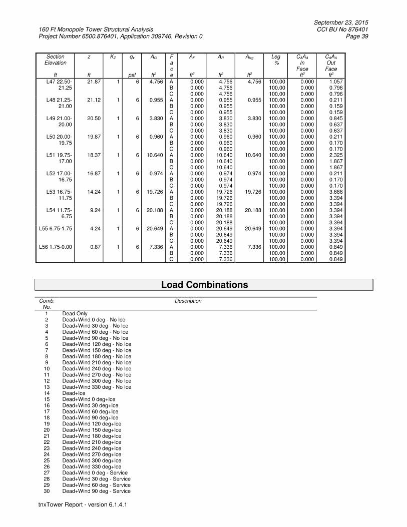
September 23, 2015 160 Ft Monopole Tower Structural Analysis CCI BU No 876401 Project Number 6500.876401, Application 309746, Revision 0 Page 39
tnxTower Report - version 6.1.4.1
Section Elevation
ft
z
ft
KZ
qz
psf
AG
ft2
F a c e
AF
ft2
AR
ft2
Aleg
ft2
Leg %
CAAA In
Face ft2
CAAA Out
Face ft2
L47 22.50-21.25
21.87 1 6 4.756 A B C
0.000 0.000 0.000
4.756 4.756 4.756
4.756 100.00 100.00 100.00
0.000 0.000 0.000
1.057 0.796 0.796
L48 21.25-21.00
21.12 1 6 0.955 A B C
0.000 0.000 0.000
0.955 0.955 0.955
0.955 100.00 100.00 100.00
0.000 0.000 0.000
0.211 0.159 0.159
L49 21.00-20.00
20.50 1 6 3.830 A B C
0.000 0.000 0.000
3.830 3.830 3.830
3.830 100.00 100.00 100.00
0.000 0.000 0.000
0.845 0.637 0.637
L50 20.00-19.75
19.87 1 6 0.960 A B C
0.000 0.000 0.000
0.960 0.960 0.960
0.960 100.00 100.00 100.00
0.000 0.000 0.000
0.211 0.170 0.170
L51 19.75-17.00
18.37 1 6 10.640 A B C
0.000 0.000 0.000
10.640 10.640 10.640
10.640 100.00 100.00 100.00
0.000 0.000 0.000
2.325 1.867 1.867
L52 17.00-16.75
16.87 1 6 0.974 A B C
0.000 0.000 0.000
0.974 0.974 0.974
0.974 100.00 100.00 100.00
0.000 0.000 0.000
0.211 0.170 0.170
L53 16.75-11.75
14.24 1 6 19.726 A B C
0.000 0.000 0.000
19.726 19.726 19.726
19.726 100.00 100.00 100.00
0.000 0.000 0.000
3.686 3.394 3.394
L54 11.75-6.75
9.24 1 6 20.188 A B C
0.000 0.000 0.000
20.188 20.188 20.188
20.188 100.00 100.00 100.00
0.000 0.000 0.000
3.394 3.394 3.394
L55 6.75-1.75 4.24 1 6 20.649 A B C
0.000 0.000 0.000
20.649 20.649 20.649
20.649 100.00 100.00 100.00
0.000 0.000 0.000
3.394 3.394 3.394
L56 1.75-0.00 0.87 1 6 7.336 A B C
0.000 0.000 0.000
7.336 7.336 7.336
7.336 100.00 100.00 100.00
0.000 0.000 0.000
0.849 0.849 0.849
Load Combinations
Comb. No.
Description
1 Dead Only 2 Dead+Wind 0 deg - No Ice 3 Dead+Wind 30 deg - No Ice 4 Dead+Wind 60 deg - No Ice 5 Dead+Wind 90 deg - No Ice 6 Dead+Wind 120 deg - No Ice 7 Dead+Wind 150 deg - No Ice 8 Dead+Wind 180 deg - No Ice 9 Dead+Wind 210 deg - No Ice 10 Dead+Wind 240 deg - No Ice 11 Dead+Wind 270 deg - No Ice 12 Dead+Wind 300 deg - No Ice 13 Dead+Wind 330 deg - No Ice 14 Dead+Ice 15 Dead+Wind 0 deg+Ice 16 Dead+Wind 30 deg+Ice 17 Dead+Wind 60 deg+Ice 18 Dead+Wind 90 deg+Ice 19 Dead+Wind 120 deg+Ice 20 Dead+Wind 150 deg+Ice 21 Dead+Wind 180 deg+Ice 22 Dead+Wind 210 deg+Ice 23 Dead+Wind 240 deg+Ice 24 Dead+Wind 270 deg+Ice 25 Dead+Wind 300 deg+Ice 26 Dead+Wind 330 deg+Ice 27 Dead+Wind 0 deg - Service 28 Dead+Wind 30 deg - Service 29 Dead+Wind 60 deg - Service 30 Dead+Wind 90 deg - Service

September 23, 2015 160 Ft Monopole Tower Structural Analysis CCI BU No 876401 Project Number 6500.876401, Application 309746, Revision 0 Page 40
tnxTower Report - version 6.1.4.1
Comb. No.
Description
31 Dead+Wind 120 deg - Service 32 Dead+Wind 150 deg - Service 33 Dead+Wind 180 deg - Service 34 Dead+Wind 210 deg - Service 35 Dead+Wind 240 deg - Service 36 Dead+Wind 270 deg - Service 37 Dead+Wind 300 deg - Service 38 Dead+Wind 330 deg - Service
Maximum Member Forces
Section
No.
Elevation ft
Component Type
Condition Gov. Load
Comb.
Force
K
Major Axis Moment
kip-ft
Minor Axis Moment
kip-ft
L1 160 - 155 Pole Max Tension 5 0.00 0.00 0.00 Max. Compression 14 -4.68 0.00 0.00 Max. Mx 11 -1.97 14.34 -0.00 Max. My 8 -1.96 0.00 -14.34 Max. Vy 11 -4.43 14.34 -0.00 Max. Vx 8 4.43 0.00 -14.34 Max. Torque 7 -0.00
L2 155 - 150 Pole Max Tension 1 0.00 0.00 0.00 Max. Compression 14 -5.97 0.00 0.00 Max. Mx 11 -2.47 39.04 -0.01 Max. My 8 -2.47 0.00 -39.04 Max. Vy 11 -5.64 39.04 -0.01 Max. Vx 8 5.64 0.00 -39.04 Max. Torque 7 -0.00
L3 150 - 145 Pole Max Tension 1 0.00 0.00 0.00 Max. Compression 14 -10.61 -0.28 -0.16 Max. Mx 5 -4.26 -89.22 -0.02 Max. My 8 -4.26 -0.04 -89.19 Max. Vy 11 -10.16 89.05 -0.04 Max. Vx 8 10.16 -0.04 -89.19 Max. Torque 3 -0.35
L4 145 - 140 Pole Max Tension 1 0.00 0.00 0.00 Max. Compression 14 -11.05 -0.28 -0.16 Max. Mx 5 -4.56 -140.67 -0.02 Max. My 8 -4.56 -0.03 -140.65 Max. Vy 11 -10.43 140.50 -0.05 Max. Vx 8 10.43 -0.03 -140.65 Max. Torque 3 -0.35
L5 140 - 135 Pole Max Tension 1 0.00 0.00 0.00 Max. Compression 14 -14.20 -0.28 -0.16 Max. Mx 5 -5.92 -203.03 -0.02 Max. My 8 -5.92 -0.02 -203.01 Max. Vy 11 -13.09 202.86 -0.06 Max. Vx 8 13.09 -0.02 -203.01 Max. Torque 3 -0.35
L6 135 - 130 Pole Max Tension 1 0.00 0.00 0.00 Max. Compression 14 -14.73 -0.28 -0.16 Max. Mx 5 -6.34 -269.15 -0.01 Max. My 8 -6.33 -0.01 -269.14 Max. Vy 11 -13.37 268.99 -0.06 Max. Vx 8 13.37 -0.01 -269.14 Max. Torque 9 0.35
L7 130 - 125.75 Pole Max Tension 1 0.00 0.00 0.00 Max. Compression 14 -21.24 0.32 0.18 Max. Mx 11 -8.81 351.74 -0.27 Max. My 2 -8.80 -0.21 352.05 Max. Vy 11 -20.21 351.74 -0.27 Max. Vx 8 20.29 0.41 -351.95 Max. Torque 9 0.35
L8 125.75 - 125.5
Pole Max Tension 1 0.00 0.00 0.00
Max. Compression 14 -21.27 0.32 0.18 Max. Mx 11 -8.86 356.79 -0.29

September 23, 2015 160 Ft Monopole Tower Structural Analysis CCI BU No 876401 Project Number 6500.876401, Application 309746, Revision 0 Page 41
tnxTower Report - version 6.1.4.1
Section
No.
Elevation ft
Component Type
Condition Gov. Load
Comb.
Force
K
Major Axis Moment
kip-ft
Minor Axis Moment
kip-ft
Max. My 2 -8.85 -0.23 357.12 Max. Vy 11 -20.23 356.79 -0.29 Max. Vx 8 20.31 0.43 -357.02 Max. Torque 3 0.19
L9 125.5 - 119.12
Pole Max Tension 1 0.00 0.00 0.00
Max. Compression 14 -21.68 0.32 0.18 Max. Mx 11 -9.18 410.30 -0.47 Max. My 2 -9.17 -0.40 410.83 Max. Vy 11 -20.47 410.30 -0.47 Max. Vx 8 20.55 0.61 -410.73 Max. Torque 3 0.19
L10 119.12 - 119 Pole Max Tension 1 0.00 0.00 0.00 Max. Compression 14 -22.83 0.32 0.18 Max. Mx 11 -10.06 490.28 -0.73 Max. My 2 -10.05 -0.66 491.11 Max. Vy 5 20.87 -490.09 0.80 Max. Vx 8 20.95 0.87 -491.01 Max. Torque 3 0.19
L11 119 - 118.75 Pole Max Tension 1 0.00 0.00 0.00 Max. Compression 14 -22.88 0.32 0.18 Max. Mx 11 -10.10 495.50 -0.75 Max. My 2 -10.09 -0.68 496.35 Max. Vy 11 -20.89 495.50 -0.75 Max. Vx 8 20.97 0.89 -496.25 Max. Torque 3 0.19
L12 118.75 - 113.75
Pole Max Tension 1 0.00 0.00 0.00
Max. Compression 14 -23.84 0.32 0.18 Max. Mx 11 -10.91 601.13 -1.09 Max. My 2 -10.90 -1.01 602.37 Max. Vy 11 -21.37 601.13 -1.09 Max. Vx 8 21.45 1.23 -602.27 Max. Torque 3 0.19
L13 113.75 - 108.75
Pole Max Tension 1 0.00 0.00 0.00
Max. Compression 14 -25.12 1.05 -0.24 Max. Mx 11 -11.89 710.01 -1.60 Max. My 8 -11.88 1.88 -711.39 Max. Vy 11 -22.11 710.01 -1.60 Max. Vx 8 22.19 1.88 -711.39 Max. Torque 7 -0.96
L14 108.75 - 103.75
Pole Max Tension 1 0.00 0.00 0.00
Max. Compression 14 -27.95 1.05 -0.24 Max. Mx 11 -14.57 825.00 -1.95 Max. My 8 -14.56 2.23 -826.76 Max. Vy 11 -25.20 825.00 -1.95 Max. Vx 8 25.27 2.23 -826.76 Max. Torque 7 -0.96
L15 103.75 - 103 Pole Max Tension 1 0.00 0.00 0.00 Max. Compression 14 -28.10 1.05 -0.24 Max. Mx 11 -14.71 843.92 -2.00 Max. My 8 -14.70 2.28 -845.74 Max. Vy 11 -25.27 843.92 -2.00 Max. Vx 8 25.35 2.28 -845.74 Max. Torque 7 -0.96
L16 103 - 102.75 Pole Max Tension 1 0.00 0.00 0.00 Max. Compression 14 -28.16 1.05 -0.24 Max. Mx 11 -14.77 850.24 -2.01 Max. My 8 -14.76 2.29 -852.08 Max. Vy 11 -25.30 850.24 -2.01 Max. Vx 8 25.37 2.29 -852.08 Max. Torque 7 -0.96
L17 102.75 - 100.208
Pole Max Tension 1 0.00 0.00 0.00
Max. Compression 14 -28.74 1.05 -0.24 Max. Mx 11 -15.27 914.90 -2.19 Max. My 8 -15.26 2.47 -916.94

September 23, 2015 160 Ft Monopole Tower Structural Analysis CCI BU No 876401 Project Number 6500.876401, Application 309746, Revision 0 Page 42
tnxTower Report - version 6.1.4.1
Section
No.
Elevation ft
Component Type
Condition Gov. Load
Comb.
Force
K
Major Axis Moment
kip-ft
Minor Axis Moment
kip-ft
Max. Vy 11 -25.59 914.90 -2.19 Max. Vx 8 25.67 2.47 -916.94 Max. Torque 7 -0.96
L18 100.208 - 95.83
Pole Max Tension 1 0.00 0.00 0.00
Max. Compression 14 -28.75 1.05 -0.24 Max. Mx 11 -15.30 916.13 -2.19 Max. My 8 -15.29 2.47 -918.17 Max. Vy 5 25.59 -915.22 1.90 Max. Vx 8 25.66 2.47 -918.17 Max. Torque 7 -0.96
L19 95.83 - 94.83
Pole Max Tension 1 0.00 0.00 0.00
Max. Compression 14 -31.15 1.05 -0.24 Max. Mx 11 -17.28 1054.43 -2.56 Max. My 8 -17.28 2.85 -1056.88 Max. Vy 11 -26.30 1054.43 -2.56 Max. Vx 8 26.38 2.85 -1056.88 Max. Torque 7 -0.96
L20 94.83 - 93.5 Pole Max Tension 1 0.00 0.00 0.00 Max. Compression 14 -31.51 1.05 -0.24 Max. Mx 11 -17.60 1089.53 -2.65 Max. My 8 -17.59 2.94 -1092.08 Max. Vy 11 -26.49 1089.53 -2.65 Max. Vx 8 26.57 2.94 -1092.08 Max. Torque 7 -0.96
L21 93.5 - 93.25 Pole Max Tension 1 0.00 0.00 0.00 Max. Compression 14 -31.59 1.05 -0.24 Max. Mx 11 -17.69 1096.15 -2.67 Max. My 8 -17.68 2.96 -1098.72 Max. Vy 11 -26.52 1096.15 -2.67 Max. Vx 8 26.59 2.96 -1098.72 Max. Torque 7 -0.96
L22 93.25 - 89.25
Pole Max Tension 1 0.00 0.00 0.00
Max. Compression 14 -32.87 1.05 -0.24 Max. Mx 11 -18.82 1203.35 -2.95 Max. My 8 -18.81 3.23 -1206.23 Max. Vy 11 -27.09 1203.35 -2.95 Max. Vx 8 27.17 3.23 -1206.23 Max. Torque 7 -0.96
L23 89.25 - 89 Pole Max Tension 1 0.00 0.00 0.00 Max. Compression 14 -32.96 1.05 -0.24 Max. Mx 11 -18.90 1210.12 -2.96 Max. My 8 -18.89 3.25 -1213.02 Max. Vy 11 -27.12 1210.12 -2.96 Max. Vx 8 27.20 3.25 -1213.02 Max. Torque 7 -0.96
L24 89 - 86.5 Pole Max Tension 1 0.00 0.00 0.00 Max. Compression 14 -33.80 1.05 -0.24 Max. Mx 11 -19.65 1278.37 -3.14 Max. My 8 -19.64 3.43 -1281.46 Max. Vy 11 -27.48 1278.37 -3.14 Max. Vx 8 27.56 3.43 -1281.46 Max. Torque 7 -0.96
L25 86.5 - 86.25 Pole Max Tension 1 0.00 0.00 0.00 Max. Compression 14 -33.87 1.05 -0.24 Max. Mx 11 -19.72 1285.24 -3.15 Max. My 8 -19.71 3.44 -1288.35 Max. Vy 11 -27.51 1285.24 -3.15 Max. Vx 8 27.59 3.44 -1288.35 Max. Torque 7 -0.96
L26 86.25 - 81.25
Pole Max Tension 1 0.00 0.00 0.00
Max. Compression 14 -35.35 1.05 -0.24 Max. Mx 11 -21.03 1424.28 -3.50 Max. My 8 -21.03 3.79 -1427.78 Max. Vy 11 -28.12 1424.28 -3.50 Max. Vx 8 28.19 3.79 -1427.78

September 23, 2015 160 Ft Monopole Tower Structural Analysis CCI BU No 876401 Project Number 6500.876401, Application 309746, Revision 0 Page 43
tnxTower Report - version 6.1.4.1
Section
No.
Elevation ft
Component Type
Condition Gov. Load
Comb.
Force
K
Major Axis Moment
kip-ft
Minor Axis Moment
kip-ft
Max. Torque 7 -0.96 L27 81.25 -
76.25 Pole Max Tension 1 0.00 0.00 0.00
Max. Compression 14 -36.85 1.05 -0.24 Max. Mx 11 -22.38 1566.25 -3.84 Max. My 8 -22.37 4.14 -1570.13 Max. Vy 11 -28.69 1566.25 -3.84 Max. Vx 8 28.77 4.14 -1570.13 Max. Torque 7 -0.96
L28 76.25 - 75.417
Pole Max Tension 1 0.00 0.00 0.00
Max. Compression 14 -37.10 1.05 -0.24 Max. Mx 11 -22.61 1590.19 -3.90 Max. My 8 -22.60 4.19 -1594.14 Max. Vy 11 -28.81 1590.19 -3.90 Max. Vx 8 28.89 4.19 -1594.14 Max. Torque 7 -0.96
L29 75.417 - 75.167
Pole Max Tension 1 0.00 0.00 0.00
Max. Compression 14 -37.18 1.05 -0.24 Max. Mx 11 -22.69 1597.39 -3.92 Max. My 8 -22.69 4.21 -1601.36 Max. Vy 5 28.84 -1596.47 3.61 Max. Vx 8 28.92 4.21 -1601.36 Max. Torque 7 -0.96
L30 75.167 - 70.167
Pole Max Tension 1 0.00 0.00 0.00
Max. Compression 14 -38.86 1.05 -0.24 Max. Mx 11 -24.19 1743.38 -4.26 Max. My 8 -24.18 4.56 -1747.74 Max. Vy 11 -29.57 1743.38 -4.26 Max. Vx 8 29.65 4.56 -1747.74 Max. Torque 7 -0.96
L31 70.167 - 65.167
Pole Max Tension 1 0.00 0.00 0.00
Max. Compression 14 -40.56 1.05 -0.24 Max. Mx 11 -25.72 1892.97 -4.60 Max. My 8 -25.71 4.90 -1897.71 Max. Vy 11 -30.28 1892.97 -4.60 Max. Vx 8 30.36 4.90 -1897.71 Max. Torque 7 -0.96
L32 65.167 - 60.167
Pole Max Tension 1 0.00 0.00 0.00
Max. Compression 14 -42.29 1.05 -0.24 Max. Mx 11 -27.27 2046.07 -4.95 Max. My 8 -27.26 5.25 -2051.20 Max. Vy 11 -30.98 2046.07 -4.95 Max. Vx 8 31.06 5.25 -2051.20 Max. Torque 7 -0.96
L33 60.167 - 59.5
Pole Max Tension 1 0.00 0.00 0.00
Max. Compression 14 -42.52 1.05 -0.24 Max. Mx 11 -27.48 2066.76 -4.99 Max. My 8 -27.48 5.29 -2071.94 Max. Vy 11 -31.07 2066.76 -4.99 Max. Vx 8 31.14 5.29 -2071.94 Max. Torque 7 -0.96
L34 59.5 - 59.25 Pole Max Tension 1 0.00 0.00 0.00 Max. Compression 14 -42.61 1.05 -0.24 Max. Mx 11 -27.57 2074.52 -5.01 Max. My 8 -27.56 5.31 -2079.73 Max. Vy 5 31.10 -2073.60 4.69 Max. Vx 8 31.17 5.31 -2079.73 Max. Torque 7 -0.96
L35 59.25 - 54.25
Pole Max Tension 1 0.00 0.00 0.00
Max. Compression 14 -44.36 1.05 -0.24 Max. Mx 11 -29.14 2231.69 -5.35 Max. My 8 -29.14 5.65 -2237.28

September 23, 2015 160 Ft Monopole Tower Structural Analysis CCI BU No 876401 Project Number 6500.876401, Application 309746, Revision 0 Page 44
tnxTower Report - version 6.1.4.1
Section
No.
Elevation ft
Component Type
Condition Gov. Load
Comb.
Force
K
Major Axis Moment
kip-ft
Minor Axis Moment
kip-ft
Max. Vy 11 -31.79 2231.69 -5.35 Max. Vx 8 31.86 5.65 -2237.28 Max. Torque 7 -0.96
L36 54.25 - 53 Pole Max Tension 1 0.00 0.00 0.00 Max. Compression 14 -44.80 1.05 -0.24 Max. Mx 11 -29.54 2271.52 -5.44 Max. My 8 -29.53 5.74 -2277.21 Max. Vy 11 -31.96 2271.52 -5.44 Max. Vx 8 32.04 5.74 -2277.21 Max. Torque 7 -0.96
L37 53 - 47.2 Pole Max Tension 1 0.00 0.00 0.00 Max. Compression 14 -44.89 1.05 -0.24 Max. Mx 11 -29.63 2278.55 -5.45 Max. My 8 -29.62 5.75 -2284.26 Max. Vy 5 31.98 -2277.62 5.13 Max. Vx 8 32.06 5.75 -2284.26 Max. Torque 7 -0.96
L38 47.2 - 46.2 Pole Max Tension 1 0.00 0.00 0.00 Max. Compression 14 -49.34 1.05 -0.24 Max. Mx 11 -33.48 2492.36 -5.90 Max. My 8 -33.48 6.21 -2498.58 Max. Vy 11 -33.00 2492.36 -5.90 Max. Vx 8 33.07 6.21 -2498.58 Max. Torque 7 -0.95
L39 46.2 - 41.2 Pole Max Tension 1 0.00 0.00 0.00 Max. Compression 14 -51.27 1.05 -0.24 Max. Mx 11 -35.24 2658.84 -6.24 Max. My 8 -35.24 6.55 -2665.44 Max. Vy 11 -33.62 2658.84 -6.24 Max. Vx 8 33.70 6.55 -2665.44 Max. Torque 7 -0.95
L40 41.2 - 39.333
Pole Max Tension 1 0.00 0.00 0.00
Max. Compression 14 -52.00 1.05 -0.24 Max. Mx 11 -35.90 2721.83 -6.37 Max. My 8 -35.90 6.67 -2728.57 Max. Vy 11 -33.89 2721.83 -6.37 Max. Vx 8 33.97 6.67 -2728.57 Max. Torque 7 -0.95
L41 39.333 - 39.083
Pole Max Tension 1 0.00 0.00 0.00
Max. Compression 14 -52.11 1.05 -0.24 Max. Mx 11 -36.02 2730.30 -6.39 Max. My 8 -36.01 6.69 -2737.06 Max. Vy 5 33.91 -2729.37 6.07 Max. Vx 8 33.98 6.69 -2737.06 Max. Torque 7 -0.95
L42 39.083 - 37.75
Pole Max Tension 1 0.00 0.00 0.00
Max. Compression 14 -52.67 1.05 -0.24 Max. Mx 11 -36.52 2775.63 -6.48 Max. My 8 -36.51 6.78 -2782.49 Max. Vy 11 -34.12 2775.63 -6.48 Max. Vx 8 34.19 6.78 -2782.49 Max. Torque 7 -0.95
L43 37.75 - 37.5 Pole Max Tension 1 0.00 0.00 0.00 Max. Compression 14 -52.77 1.05 -0.24 Max. Mx 11 -36.62 2784.16 -6.49 Max. My 8 -36.62 6.80 -2791.04 Max. Vy 5 34.14 -2783.22 6.17 Max. Vx 8 34.22 6.80 -2791.04 Max. Torque 7 -0.95
L44 37.5 - 32.5 Pole Max Tension 1 0.00 0.00 0.00 Max. Compression 14 -54.75 1.05 -0.24 Max. Mx 11 -38.42 2956.34 -6.83 Max. My 8 -38.42 7.14 -2963.61 Max. Vy 11 -34.75 2956.34 -6.83 Max. Vx 8 34.83 7.14 -2963.61 Max. Torque 7 -0.95

September 23, 2015 160 Ft Monopole Tower Structural Analysis CCI BU No 876401 Project Number 6500.876401, Application 309746, Revision 0 Page 45
tnxTower Report - version 6.1.4.1
Section
No.
Elevation ft
Component Type
Condition Gov. Load
Comb.
Force
K
Major Axis Moment
kip-ft
Minor Axis Moment
kip-ft
L45 32.5 - 27.5 Pole Max Tension 1 0.00 0.00 0.00 Max. Compression 14 -56.75 1.05 -0.24 Max. Mx 11 -40.26 3131.45 -7.17 Max. My 8 -40.25 7.48 -3139.10 Max. Vy 11 -35.32 3131.45 -7.17 Max. Vx 8 35.39 7.48 -3139.10 Max. Torque 7 -0.95
L46 27.5 - 22.5 Pole Max Tension 1 0.00 0.00 0.00 Max. Compression 14 -58.79 1.05 -0.24 Max. Mx 11 -42.12 3309.42 -7.51 Max. My 8 -42.12 7.81 -3317.45 Max. Vy 11 -35.90 3309.42 -7.51 Max. Vx 8 35.98 7.81 -3317.45 Max. Torque 7 -0.95
L47 22.5 - 21.25 Pole Max Tension 1 0.00 0.00 0.00 Max. Compression 14 -59.30 1.05 -0.24 Max. Mx 11 -42.58 3354.37 -7.59 Max. My 8 -42.58 7.90 -3362.49 Max. Vy 11 -36.05 3354.37 -7.59 Max. Vx 8 36.13 7.90 -3362.49 Max. Torque 7 -0.95
L48 21.25 - 21 Pole Max Tension 1 0.00 0.00 0.00 Max. Compression 14 -59.41 1.05 -0.24 Max. Mx 11 -42.70 3363.38 -7.61 Max. My 8 -42.70 7.92 -3371.53 Max. Vy 5 36.07 -3362.44 7.29 Max. Vx 8 36.15 7.92 -3371.53 Max. Torque 7 -0.95
L49 21 - 20 Pole Max Tension 1 0.00 0.00 0.00 Max. Compression 14 -59.86 1.05 -0.24 Max. Mx 11 -43.10 3399.51 -7.68 Max. My 8 -43.10 7.98 -3407.73 Max. Vy 11 -36.20 3399.51 -7.68 Max. Vx 8 36.28 7.98 -3407.73 Max. Torque 7 -0.95
L50 20 - 19.75 Pole Max Tension 1 0.00 0.00 0.00 Max. Compression 14 -59.98 1.05 -0.24 Max. Mx 11 -43.22 3408.56 -7.69 Max. My 8 -43.22 8.00 -3416.80 Max. Vy 5 36.22 -3407.62 7.37 Max. Vx 8 36.30 8.00 -3416.80 Max. Torque 7 -0.95
L51 19.75 - 17 Pole Max Tension 1 0.00 0.00 0.00 Max. Compression 14 -61.31 1.05 -0.24 Max. Mx 11 -44.43 3508.64 -7.88 Max. My 8 -44.43 8.18 -3517.09 Max. Vy 11 -36.58 3508.64 -7.88 Max. Vx 8 36.66 8.18 -3517.09 Max. Torque 7 -0.95
L52 17 - 16.75 Pole Max Tension 1 0.00 0.00 0.00 Max. Compression 14 -61.43 1.05 -0.24 Max. Mx 11 -44.56 3517.78 -7.89 Max. My 8 -44.55 8.20 -3526.25 Max. Vy 5 36.60 -3516.84 7.57 Max. Vx 8 36.68 8.20 -3526.25 Max. Torque 7 -0.94
L53 16.75 - 11.75
Pole Max Tension 1 0.00 0.00 0.00
Max. Compression 14 -63.86 1.05 -0.24 Max. Mx 11 -46.78 3702.30 -8.23 Max. My 8 -46.78 8.53 -3711.15 Max. Vy 11 -37.22 3702.30 -8.23 Max. Vx 8 37.30 8.53 -3711.15 Max. Torque 7 -0.94
L54 11.75 - 6.75 Pole Max Tension 1 0.00 0.00 0.00 Max. Compression 14 -66.32 1.05 -0.24 Max. Mx 11 -49.04 3889.86 -8.56 Max. My 8 -49.04 8.87 -3899.08 Max. Vy 11 -37.83 3889.86 -8.56

September 23, 2015 160 Ft Monopole Tower Structural Analysis CCI BU No 876401 Project Number 6500.876401, Application 309746, Revision 0 Page 46
tnxTower Report - version 6.1.4.1
Section
No.
Elevation ft
Component Type
Condition Gov. Load
Comb.
Force
K
Major Axis Moment
kip-ft
Minor Axis Moment
kip-ft
Max. Vx 8 37.90 8.87 -3899.08 Max. Torque 7 -0.94
L55 6.75 - 1.75 Pole Max Tension 1 0.00 0.00 0.00 Max. Compression 14 -68.82 1.05 -0.24 Max. Mx 11 -51.33 4080.42 -8.89 Max. My 8 -51.33 9.20 -4090.02 Max. Vy 11 -38.43 4080.42 -8.89 Max. Vx 8 38.50 9.20 -4090.02 Max. Torque 7 -0.94
L56 1.75 - 0 Pole Max Tension 1 0.00 0.00 0.00 Max. Compression 14 -69.70 1.05 -0.24 Max. Mx 11 -52.13 4147.79 -9.01 Max. My 8 -52.13 9.31 -4157.52 Max. Vy 11 -38.62 4147.79 -9.01 Max. Vx 8 38.69 9.31 -4157.52 Max. Torque 7 -0.94
Maximum Reactions
Location Condition Gov. Load
Comb.
Vertical K
Horizontal, X K
Horizontal, Z K
Pole Max. Vert 21 69.70 0.01 -10.68 Max. Hx 11 52.15 38.59 -0.07 Max. Hz 2 52.15 -0.07 38.66 Max. Mx 2 4157.20 -0.07 38.66 Max. Mz 5 4146.85 -38.59 0.07 Max. Torsion 13 0.94 19.24 33.45 Min. Vert 1 52.15 0.00 0.00 Min. Hx 5 52.15 -38.59 0.07 Min. Hz 8 52.15 0.07 -38.66 Min. Mx 8 -4157.52 0.07 -38.66 Min. Mz 11 -4147.79 38.59 -0.07 Min. Torsion 7 -0.94 -19.24 -33.45
Tower Mast Reaction Summary
Load Combination
Vertical
K
Shearx
K
Shearz
K
Overturning Moment, Mx
kip-ft
Overturning Moment, Mz
kip-ft
Torque
kip-ft
Dead Only 52.15 0.00 0.00 0.15 0.45 0.00 Dead+Wind 0 deg - No Ice 52.15 0.07 -38.66 -4157.20 -8.38 -0.90 Dead+Wind 30 deg - No Ice 52.15 19.35 -33.52 -3604.63 -2080.83 -0.62 Dead+Wind 60 deg - No Ice 52.15 33.45 -19.39 -2086.18 -3595.62 -0.18 Dead+Wind 90 deg - No Ice 52.15 38.59 -0.07 -8.69 -4146.85 0.31 Dead+Wind 120 deg - No Ice 52.15 33.39 19.28 2071.20 -3586.81 0.72 Dead+Wind 150 deg - No Ice 52.15 19.24 33.45 3596.14 -2065.53 0.94 Dead+Wind 180 deg - No Ice 52.15 -0.07 38.66 4157.52 9.31 0.90 Dead+Wind 210 deg - No Ice 52.15 -19.35 33.52 3604.95 2081.77 0.62 Dead+Wind 240 deg - No Ice 52.15 -33.45 19.39 2086.50 3596.56 0.17 Dead+Wind 270 deg - No Ice 52.15 -38.59 0.07 9.01 4147.79 -0.32 Dead+Wind 300 deg - No Ice 52.15 -33.39 -19.28 -2070.88 3587.74 -0.72 Dead+Wind 330 deg - No Ice 52.15 -19.24 -33.45 -3595.82 2066.47 -0.94 Dead+Ice 69.70 0.00 0.00 0.24 1.05 0.00 Dead+Wind 0 deg+Ice 69.70 0.01 -10.68 -1162.36 -0.68 -0.30 Dead+Wind 30 deg+Ice 69.70 5.34 -9.26 -1007.51 -580.64 -0.19 Dead+Wind 60 deg+Ice 69.70 9.24 -5.35 -582.63 -1004.71 -0.03 Dead+Wind 90 deg+Ice 69.70 10.67 -0.01 -1.56 -1159.26 0.14 Dead+Wind 120 deg+Ice 69.70 9.23 5.33 579.99 -1002.89 0.27 Dead+Wind 150 deg+Ice 69.70 5.32 9.24 1006.22 -577.48 0.33 Dead+Wind 180 deg+Ice 69.70 -0.01 10.68 1162.89 2.97 0.30

September 23, 2015 160 Ft Monopole Tower Structural Analysis CCI BU No 876401 Project Number 6500.876401, Application 309746, Revision 0 Page 47
tnxTower Report - version 6.1.4.1
Load Combination
Vertical
K
Shearx
K
Shearz
K
Overturning Moment, Mx
kip-ft
Overturning Moment, Mz
kip-ft
Torque
kip-ft
Dead+Wind 210 deg+Ice 69.70 -5.34 9.26 1008.04 582.93 0.19 Dead+Wind 240 deg+Ice 69.70 -9.24 5.35 583.16 1007.00 0.03 Dead+Wind 270 deg+Ice 69.70 -10.67 0.01 2.09 1161.55 -0.14 Dead+Wind 300 deg+Ice 69.70 -9.23 -5.33 -579.47 1005.18 -0.27 Dead+Wind 330 deg+Ice 69.70 -5.32 -9.24 -1005.69 579.77 -0.33 Dead+Wind 0 deg - Service 52.15 0.02 -13.38 -1440.17 -2.59 -0.31 Dead+Wind 30 deg - Service 52.15 6.70 -11.60 -1248.73 -720.60 -0.22 Dead+Wind 60 deg - Service 52.15 11.58 -6.71 -722.66 -1245.40 -0.06 Dead+Wind 90 deg - Service 52.15 13.35 -0.02 -2.90 -1436.37 0.11 Dead+Wind 120 deg - Service
52.15 11.55 6.67 717.68 -1242.34 0.25
Dead+Wind 150 deg - Service
52.15 6.66 11.57 1246.00 -715.30 0.33
Dead+Wind 180 deg - Service
52.15 -0.02 13.38 1440.50 3.54 0.31
Dead+Wind 210 deg - Service
52.15 -6.70 11.60 1249.06 721.55 0.22
Dead+Wind 240 deg - Service
52.15 -11.58 6.71 722.98 1246.35 0.06
Dead+Wind 270 deg - Service
52.15 -13.35 0.02 3.23 1437.32 -0.11
Dead+Wind 300 deg - Service
52.15 -11.55 -6.67 -717.35 1243.29 -0.25
Dead+Wind 330 deg - Service
52.15 -6.66 -11.57 -1245.67 716.24 -0.33
Solution Summary
Load
Comb.
Sum of Applied Forces Sum of Reactions % Error PX
K PY K
PZ K
PX K
PY K
PZ K
1 0.00 -52.15 0.00 0.00 52.15 0.00 0.000% 2 0.07 -52.15 -38.66 -0.07 52.15 38.66 0.000% 3 19.35 -52.15 -33.52 -19.35 52.15 33.52 0.000% 4 33.45 -52.15 -19.39 -33.45 52.15 19.39 0.000% 5 38.59 -52.15 -0.07 -38.59 52.15 0.07 0.000% 6 33.39 -52.15 19.28 -33.39 52.15 -19.28 0.000% 7 19.24 -52.15 33.45 -19.24 52.15 -33.45 0.000% 8 -0.07 -52.15 38.66 0.07 52.15 -38.66 0.000% 9 -19.35 -52.15 33.52 19.35 52.15 -33.52 0.000% 10 -33.45 -52.15 19.39 33.45 52.15 -19.39 0.000% 11 -38.59 -52.15 0.07 38.59 52.15 -0.07 0.000% 12 -33.39 -52.15 -19.28 33.39 52.15 19.28 0.000% 13 -19.24 -52.15 -33.45 19.24 52.15 33.45 0.000% 14 0.00 -69.70 0.00 0.00 69.70 0.00 0.000% 15 0.01 -69.70 -10.68 -0.01 69.70 10.68 0.000% 16 5.34 -69.70 -9.26 -5.34 69.70 9.26 0.000% 17 9.24 -69.70 -5.35 -9.24 69.70 5.35 0.000% 18 10.67 -69.70 -0.01 -10.67 69.70 0.01 0.000% 19 9.23 -69.70 5.33 -9.23 69.70 -5.33 0.000% 20 5.32 -69.70 9.24 -5.32 69.70 -9.24 0.000% 21 -0.01 -69.70 10.68 0.01 69.70 -10.68 0.000% 22 -5.34 -69.70 9.26 5.34 69.70 -9.26 0.000% 23 -9.24 -69.70 5.35 9.24 69.70 -5.35 0.000% 24 -10.67 -69.70 0.01 10.67 69.70 -0.01 0.000% 25 -9.23 -69.70 -5.33 9.23 69.70 5.33 0.000% 26 -5.32 -69.70 -9.24 5.32 69.70 9.24 0.000% 27 0.02 -52.15 -13.38 -0.02 52.15 13.38 0.000% 28 6.70 -52.15 -11.60 -6.70 52.15 11.60 0.000% 29 11.58 -52.15 -6.71 -11.58 52.15 6.71 0.000% 30 13.35 -52.15 -0.02 -13.35 52.15 0.02 0.000% 31 11.55 -52.15 6.67 -11.55 52.15 -6.67 0.000% 32 6.66 -52.15 11.57 -6.66 52.15 -11.57 0.000% 33 -0.02 -52.15 13.38 0.02 52.15 -13.38 0.000% 34 -6.70 -52.15 11.60 6.70 52.15 -11.60 0.000% 35 -11.58 -52.15 6.71 11.58 52.15 -6.71 0.000%

September 23, 2015 160 Ft Monopole Tower Structural Analysis CCI BU No 876401 Project Number 6500.876401, Application 309746, Revision 0 Page 48
tnxTower Report - version 6.1.4.1
Load
Comb.
Sum of Applied Forces Sum of Reactions % Error PX
K PY K
PZ K
PX K
PY K
PZ K
36 -13.35 -52.15 0.02 13.35 52.15 -0.02 0.000% 37 -11.55 -52.15 -6.67 11.55 52.15 6.67 0.000% 38 -6.66 -52.15 -11.57 6.66 52.15 11.57 0.000%
Non-Linear Convergence Results
Load Combination
Converged? Number of Cycles
Displacement Tolerance
Force Tolerance
1 Yes 4 0.00000001 0.00000001 2 Yes 6 0.00000001 0.00005364 3 Yes 7 0.00000001 0.00010222 4 Yes 7 0.00000001 0.00010367 5 Yes 5 0.00000001 0.00051215 6 Yes 7 0.00000001 0.00010425 7 Yes 7 0.00000001 0.00010084 8 Yes 6 0.00000001 0.00008690 9 Yes 7 0.00000001 0.00010464 10 Yes 7 0.00000001 0.00010317 11 Yes 6 0.00000001 0.00004578 12 Yes 7 0.00000001 0.00010139 13 Yes 7 0.00000001 0.00010451 14 Yes 4 0.00000001 0.00000001 15 Yes 6 0.00000001 0.00014278 16 Yes 6 0.00000001 0.00099302 17 Yes 7 0.00000001 0.00007912 18 Yes 6 0.00000001 0.00012377 19 Yes 7 0.00000001 0.00008082 20 Yes 6 0.00000001 0.00097030 21 Yes 6 0.00000001 0.00014700 22 Yes 7 0.00000001 0.00008142 23 Yes 7 0.00000001 0.00007919 24 Yes 6 0.00000001 0.00012638 25 Yes 6 0.00000001 0.00098170 26 Yes 7 0.00000001 0.00008184 27 Yes 5 0.00000001 0.00043921 28 Yes 6 0.00000001 0.00025823 29 Yes 6 0.00000001 0.00026418 30 Yes 5 0.00000001 0.00031208 31 Yes 6 0.00000001 0.00026592 32 Yes 6 0.00000001 0.00025264 33 Yes 5 0.00000001 0.00048735 34 Yes 6 0.00000001 0.00026919 35 Yes 6 0.00000001 0.00026259 36 Yes 5 0.00000001 0.00033711 37 Yes 6 0.00000001 0.00025426 38 Yes 6 0.00000001 0.00026849
Maximum Tower Deflections - Service Wind
Section No.
Elevation
ft
Horz. Deflection
in
Gov. Load
Comb.
Tilt °
Twist °
L1 160 - 155 37.410 34 2.3444 0.0010 L2 155 - 150 34.958 34 2.3374 0.0010 L3 150 - 145 32.525 34 2.3084 0.0010 L4 145 - 140 30.137 34 2.2486 0.0009 L5 140 - 135 27.828 34 2.1578 0.0009 L6 135 - 130 25.627 34 2.0427 0.0010 L7 130 - 125.75 23.559 34 1.9063 0.0011 L8 125.75 - 125.5 21.919 34 1.7757 0.0012

September 23, 2015 160 Ft Monopole Tower Structural Analysis CCI BU No 876401 Project Number 6500.876401, Application 309746, Revision 0 Page 49
tnxTower Report - version 6.1.4.1
Section No.
Elevation
ft
Horz. Deflection
in
Gov. Load
Comb.
Tilt °
Twist °
L9 125.5 - 119.12 21.826 34 1.7713 0.0012 L10 122.87 - 119 20.864 34 1.7226 0.0011 L11 119 - 118.75 19.483 34 1.6851 0.0011 L12 118.75 - 113.75 19.394 34 1.6811 0.0011 L13 113.75 - 108.75 17.678 34 1.5965 0.0011 L14 108.75 - 103.75 16.054 34 1.5052 0.0011 L15 103.75 - 103 14.529 34 1.4082 0.0009 L16 103 - 102.75 14.309 34 1.3935 0.0009 L17 102.75 - 100.208 14.236 34 1.3885 0.0009 L18 100.208 - 95.83 13.510 34 1.3370 0.0008 L19 100.16 - 94.83 13.497 34 1.3362 0.0008 L20 94.83 - 93.5 12.032 34 1.2821 0.0008 L21 93.5 - 93.25 11.678 34 1.2599 0.0007 L22 93.25 - 89.25 11.612 34 1.2567 0.0007 L23 89.25 - 89 10.582 34 1.2022 0.0007 L24 89 - 86.5 10.519 34 1.1990 0.0007 L25 86.5 - 86.25 9.900 34 1.1664 0.0006 L26 86.25 - 81.25 9.839 34 1.1623 0.0006 L27 81.25 - 76.25 8.666 34 1.0786 0.0006 L28 76.25 - 75.417 7.581 34 0.9935 0.0005 L29 75.417 - 75.167 7.409 34 0.9795 0.0005 L30 75.167 - 70.167 7.358 34 0.9759 0.0005 L31 70.167 - 65.167 6.375 34 0.9017 0.0004 L32 65.167 - 60.167 5.470 34 0.8271 0.0004 L33 60.167 - 59.5 4.643 34 0.7521 0.0003 L34 59.5 - 59.25 4.538 34 0.7422 0.0003 L35 59.25 - 54.25 4.500 34 0.7385 0.0003 L36 54.25 - 53 3.766 34 0.6634 0.0003 L37 53 - 47.2 3.594 34 0.6450 0.0003 L38 52.78 - 46.2 3.565 34 0.6417 0.0003 L39 46.2 - 41.2 2.714 34 0.5875 0.0002 L40 41.2 - 39.333 2.135 34 0.5171 0.0002 L41 39.333 - 39.083 1.938 34 0.4916 0.0002 L42 39.083 - 37.75 1.912 34 0.4885 0.0002 L43 37.75 - 37.5 1.778 34 0.4719 0.0002 L44 37.5 - 32.5 1.754 34 0.4685 0.0002 L45 32.5 - 27.5 1.300 34 0.3992 0.0001 L46 27.5 - 22.5 0.918 34 0.3301 0.0001 L47 22.5 - 21.25 0.608 34 0.2623 0.0001 L48 21.25 - 21 0.541 34 0.2457 0.0001 L49 21 - 20 0.528 34 0.2425 0.0001 L50 20 - 19.75 0.479 34 0.2298 0.0001 L51 19.75 - 17 0.467 34 0.2269 0.0001 L52 17 - 16.75 0.345 34 0.1950 0.0001 L53 16.75 - 11.75 0.335 34 0.1922 0.0001 L54 11.75 - 6.75 0.164 34 0.1344 0.0000 L55 6.75 - 1.75 0.054 34 0.0768 0.0000 L56 1.75 - 0 0.004 34 0.0195 0.0000
Critical Deflections and Radius of Curvature - Service Wind
Elevation
ft
Appurtenance Gov. Load
Comb.
Deflection
in
Tilt °
Twist °
Radius of Curvature
ft
159.00 APXVSPP18-C-A20 w/ Mount Pipe
34 36.919 2.3438 0.0011 16167
157.00 800MHz 2X50W RRH W/FILTER 34 35.938 2.3418 0.0011 16167 152.00 (2) TME-RRUS-11 34 33.494 2.3234 0.0011 9029 150.00 (2) 7770.00 w/ Mount Pipe 34 32.525 2.3084 0.0011 6636 139.00 APXV18-203219-C-A20 w/
Mount Pipe 34 27.379 2.1362 0.0009 2659
127.00 (2) LNX-6514DS-A1M w/ Mount Pipe
34 22.389 1.8056 0.0012 2134
109.00 DB589 34 16.133 1.5100 0.0011 3054 105.00 (2) 800 10504 w/ Mount Pipe 34 14.901 1.4327 0.0010 2936

September 23, 2015 160 Ft Monopole Tower Structural Analysis CCI BU No 876401 Project Number 6500.876401, Application 309746, Revision 0 Page 50
tnxTower Report - version 6.1.4.1
Maximum Tower Deflections - Design Wind
Section No.
Elevation
ft
Horz. Deflection
in
Gov. Load
Comb.
Tilt °
Twist °
L1 160 - 155 107.609 9 6.7507 0.0026 L2 155 - 150 100.574 9 6.7306 0.0026 L3 150 - 145 93.592 9 6.6472 0.0026 L4 145 - 140 86.738 9 6.4754 0.0024 L5 140 - 135 80.110 9 6.2145 0.0026 L6 135 - 130 73.790 9 5.8840 0.0030 L7 130 - 125.75 67.846 9 5.4916 0.0033 L8 125.75 - 125.5 63.132 9 5.1161 0.0033 L9 125.5 - 119.12 62.865 9 5.1036 0.0033
L10 122.87 - 119 60.098 9 4.9635 0.0033 L11 119 - 118.75 56.125 9 4.8556 0.0032 L12 118.75 - 113.75 55.872 9 4.8442 0.0032 L13 113.75 - 108.75 50.935 9 4.6007 0.0032 L14 108.75 - 103.75 46.262 9 4.3380 0.0031 L15 103.75 - 103 41.871 9 4.0588 0.0026 L16 103 - 102.75 41.238 9 4.0165 0.0026 L17 102.75 - 100.208 41.028 9 4.0023 0.0026 L18 100.208 - 95.83 38.940 9 3.8541 0.0024 L19 100.16 - 94.83 38.901 9 3.8517 0.0024 L20 94.83 - 93.5 34.682 9 3.6961 0.0022 L21 93.5 - 93.25 33.662 9 3.6322 0.0021 L22 93.25 - 89.25 33.473 9 3.6228 0.0021 L23 89.25 - 89 30.507 9 3.4661 0.0019 L24 89 - 86.5 30.326 9 3.4569 0.0019 L25 86.5 - 86.25 28.542 9 3.3629 0.0018 L26 86.25 - 81.25 28.366 9 3.3511 0.0018 L27 81.25 - 76.25 24.986 9 3.1099 0.0016 L28 76.25 - 75.417 21.861 9 2.8648 0.0014 L29 75.417 - 75.167 21.365 9 2.8245 0.0014 L30 75.167 - 70.167 21.217 9 2.8141 0.0013 L31 70.167 - 65.167 18.384 9 2.6006 0.0012 L32 65.167 - 60.167 15.775 9 2.3855 0.0010 L33 60.167 - 59.5 13.391 9 2.1693 0.0009 L34 59.5 - 59.25 13.090 9 2.1408 0.0009 L35 59.25 - 54.25 12.979 9 2.1301 0.0009 L36 54.25 - 53 10.862 9 1.9136 0.0008 L37 53 - 47.2 10.369 9 1.8605 0.0007 L38 52.78 - 46.2 10.283 9 1.8511 0.0007 L39 46.2 - 41.2 7.828 9 1.6947 0.0006 L40 41.2 - 39.333 6.160 9 1.4919 0.0006 L41 39.333 - 39.083 5.591 9 1.4182 0.0005 L42 39.083 - 37.75 5.517 9 1.4092 0.0005 L43 37.75 - 37.5 5.131 9 1.3615 0.0005 L44 37.5 - 32.5 5.060 9 1.3516 0.0005 L45 32.5 - 27.5 3.749 9 1.1518 0.0004 L46 27.5 - 22.5 2.648 9 0.9524 0.0003 L47 22.5 - 21.25 1.754 9 0.7568 0.0002 L48 21.25 - 21 1.562 9 0.7090 0.0002 L49 21 - 20 1.525 9 0.6999 0.0002 L50 20 - 19.75 1.382 9 0.6630 0.0002 L51 19.75 - 17 1.348 9 0.6546 0.0002 L52 17 - 16.75 0.997 9 0.5628 0.0002 L53 16.75 - 11.75 0.968 9 0.5545 0.0002 L54 11.75 - 6.75 0.475 9 0.3877 0.0001 L55 6.75 - 1.75 0.156 9 0.2217 0.0001 L56 1.75 - 0 0.010 9 0.0564 0.0000
Critical Deflections and Radius of Curvature - Design Wind

September 23, 2015 160 Ft Monopole Tower Structural Analysis CCI BU No 876401 Project Number 6500.876401, Application 309746, Revision 0 Page 51
tnxTower Report - version 6.1.4.1
Elevation
ft
Appurtenance Gov. Load
Comb.
Deflection
in
Tilt °
Twist °
Radius of Curvature
ft
159.00 APXVSPP18-C-A20 w/ Mount Pipe
9 106.201 6.7490 0.0033 5767
157.00 800MHz 2X50W RRH W/FILTER 9 103.385 6.7433 0.0033 5767 152.00 (2) TME-RRUS-11 9 96.374 6.6905 0.0033 3223 150.00 (2) 7770.00 w/ Mount Pipe 9 93.592 6.6472 0.0033 2369 139.00 APXV18-203219-C-A20 w/
Mount Pipe 9 78.819 6.1525 0.0027 945
127.00 (2) LNX-6514DS-A1M w/ Mount Pipe
9 64.484 5.2022 0.0034 753
109.00 DB589 9 46.489 4.3516 0.0031 1073 105.00 (2) 800 10504 w/ Mount Pipe 9 42.942 4.1293 0.0028 1031
Compression Checks
Pole Design Data
Section No.
Elevation
ft
Size
L
ft
Lu
ft
Kl/r
Fa
ksi
A
in2
Actual P K
Allow. Pa K
Ratio P
Pa
L1 160 - 155 (1) TP17.6204x16.5x0.1875 5.00 0.00 0.0 39.000 10.3747 -1.96 404.61 0.005 L2 155 - 150 (2) TP18.7407x17.6204x0.187
5 5.00 0.00 0.0 39.000 11.0415 -2.47 430.62 0.006
L3 150 - 145 (3) TP19.8611x18.7407x0.1875
5.00 0.00 0.0 39.000 11.7082 -4.26 456.62 0.009
L4 145 - 140 (4) TP20.9814x19.8611x0.1875
5.00 0.00 0.0 39.000 12.3750 -4.56 482.62 0.009
L5 140 - 135 (5) TP22.1018x20.9814x0.1875
5.00 0.00 0.0 39.000 13.0417 -5.92 508.63 0.012
L6 135 - 130 (6) TP23.2221x22.1018x0.1875
5.00 0.00 0.0 39.000 13.7085 -6.34 534.63 0.012
L7 130 - 125.75 (7)
TP24.1744x23.2221x0.1875
4.25 0.00 0.0 39.000 14.2752 -8.79 556.73 0.016
L8 125.75 - 125.5 (8)
TP24.2304x24.1744x0.3688
0.25 0.00 0.0 39.000 27.9280 -8.84 1089.19 0.008
L9 125.5 - 119.12 (9)
TP25.66x24.2304x0.3625 6.38 0.00 0.0 39.000 28.1399 -9.17 1097.46 0.008
L10 119.12 - 119 (10)
TP25.2956x24.4447x0.425 3.87 0.00 0.0 39.000 33.5492 -10.05 1308.42 0.008
L11 119 - 118.75 (11)
TP25.3506x25.2956x0.5 0.25 0.00 0.0 39.000 39.4379 -10.08 1538.08 0.007
L12 118.75 - 113.75 (12)
TP26.4499x25.3506x0.4875
5.00 0.00 0.0 39.000 40.1723 -10.89 1566.72 0.007
L13 113.75 - 108.75 (13)
TP27.5493x26.4499x0.475 5.00 0.00 0.0 39.000 40.8186 -11.88 1591.92 0.007
L14 108.75 - 103.75 (14)
TP28.6486x27.5493x0.4625
5.00 0.00 0.0 39.000 41.3765 -14.56 1613.69 0.009
L15 103.75 - 103 (15)
TP28.8135x28.6486x0.4625
0.75 0.00 0.0 39.000 41.6186 -14.70 1623.13 0.009
L16 103 - 102.75 (16)
TP28.8685x28.8135x0.4625
0.25 0.00 0.0 39.000 41.6993 -14.75 1626.27 0.009
L17 102.75 - 100.208 (17)
TP29.4274x28.8685x0.4563
2.54 0.00 0.0 39.000 41.9542 -15.26 1636.21 0.009
L18 100.208 - 95.83 (18)
TP30.39x29.4274x0.5375 4.38 0.00 0.0 39.000 49.3049 -15.28 1922.89 0.008
L19 95.83 - 94.83 (19)
TP30.1187x28.938x0.6 5.33 0.00 0.0 39.000 56.2154 -17.27 2192.40 0.008
L20 94.83 - 93.5 (20)
TP30.4133x30.1187x0.6 1.33 0.00 0.0 39.000 56.7765 -17.59 2214.28 0.008
L21 93.5 - 93.25 (21)
TP30.4687x30.4133x0.7875
0.25 0.00 0.0 39.000 74.1889 -17.67 2893.37 0.006
L22 93.25 - 89.25 TP31.3548x30.4687x0.762 4.00 0.00 0.0 39.000 74.0388 -18.81 2887.51 0.007

September 23, 2015 160 Ft Monopole Tower Structural Analysis CCI BU No 876401 Project Number 6500.876401, Application 309746, Revision 0 Page 52
tnxTower Report - version 6.1.4.1
Section No.
Elevation
ft
Size
L
ft
Lu
ft
Kl/r
Fa
ksi
A
in2
Actual P K
Allow. Pa K
Ratio P
Pa
(22) 5 L23 89.25 - 89 (23) TP31.4102x31.3548x0.812
5 0.25 0.00 0.0 39.000 78.9076 -18.89 3077.40 0.006
L24 89 - 86.5 (24) TP31.964x31.4102x0.8 2.50 0.00 0.0 39.000 79.1317 -19.63 3086.14 0.006 L25 86.5 - 86.25
(25) TP32.0194x31.964x0.625 0.25 0.00 0.0 39.000 62.2786 -19.71 2428.87 0.008
L26 86.25 - 81.25 (26)
TP33.127x32.0194x0.6125 5.00 0.00 0.0 39.000 63.2107 -21.02 2465.22 0.009
L27 81.25 - 76.25 (27)
TP34.2347x33.127x0.6 5.00 0.00 0.0 39.000 64.0538 -22.37 2498.10 0.009
L28 76.25 - 75.417 (28)
TP34.4192x34.2347x0.6 0.83 0.00 0.0 39.000 64.4053 -22.60 2511.81 0.009
L29 75.417 - 75.167 (29)
TP34.4746x34.4192x0.7125
0.25 0.00 0.0 39.000 76.3521 -22.68 2977.73 0.008
L30 75.167 - 70.167 (30)
TP35.5822x34.4746x0.6875
5.00 0.00 0.0 39.000 76.1446 -24.18 2969.64 0.008
L31 70.167 - 65.167 (31)
TP36.6898x35.5822x0.675 5.00 0.00 0.0 39.000 77.1600 -25.71 3009.24 0.009
L32 65.167 - 60.167 (32)
TP37.7975x36.6898x0.6625
5.00 0.00 0.0 39.000 78.0865 -27.26 3045.37 0.009
L33 60.167 - 59.5 (33)
TP37.9452x37.7975x0.6625
0.67 0.00 0.0 39.000 78.3972 -27.47 3057.49 0.009
L34 59.5 - 59.25 (34)
TP38.0006x37.9452x0.6625
0.25 0.00 0.0 39.000 78.5136 -27.56 3062.03 0.009
L35 59.25 - 54.25 (35)
TP39.1082x38.0006x0.65 5.00 0.00 0.0 39.000 79.3432 -29.13 3094.38 0.009
L36 54.25 - 53 (36) TP39.3851x39.1082x0.65 1.25 0.00 0.0 39.000 79.9145 -29.53 3116.66 0.009 L37 53 - 47.2 (37) TP40.67x39.3851x0.65 5.80 0.00 0.0 39.000 80.0150 -29.62 3120.59 0.009 L38 47.2 - 46.2
(38) TP40.2664x38.8089x0.712
5 6.58 0.00 0.0 39.000 89.4501 -33.47 3488.56 0.010
L39 46.2 - 41.2 (39)
TP41.3739x40.2664x0.7 5.00 0.00 0.0 39.000 90.3693 -35.24 3524.40 0.010
L40 41.2 - 39.333 (40)
TP41.7875x41.3739x0.7 1.87 0.00 0.0 39.000 91.2882 -35.89 3560.24 0.010
L41 39.333 - 39.083 (41)
TP41.8429x41.7875x0.775 0.25 0.00 0.0 39.000 101.0210
-36.01 3939.81 0.009
L42 39.083 - 37.75 (42)
TP42.1381x41.8429x0.775 1.33 0.00 0.0 39.000 101.7470
-36.51 3968.14 0.009
L43 37.75 - 37.5 (43)
TP42.1935x42.1381x0.7 0.25 0.00 0.0 39.000 92.1903 -36.61 3595.42 0.010
L44 37.5 - 32.5 (44)
TP43.301x42.1935x0.6875 5.00 0.00 0.0 39.000 92.9881 -38.41 3626.53 0.011
L45 32.5 - 27.5 (45)
TP44.4086x43.301x0.675 5.00 0.00 0.0 39.000 93.6970 -40.25 3654.18 0.011
L46 27.5 - 22.5 (46)
TP45.5161x44.4086x0.675 5.00 0.00 0.0 39.000 96.0698 -42.11 3746.72 0.011
L47 22.5 - 21.25 (47)
TP45.793x45.5161x0.675 1.25 0.00 0.0 39.000 96.6630 -42.58 3769.86 0.011
L48 21.25 - 21 (48) TP45.8484x45.793x0.7125 0.25 0.00 0.0 39.000 102.0740
-42.70 3980.87 0.011
L49 21 - 20 (49) TP46.0699x45.8484x0.7 1.00 0.00 0.0 39.000 100.8030
-43.10 3931.31 0.011
L50 20 - 19.75 (50) TP46.1252x46.0699x0.775 0.25 0.00 0.0 39.000 111.5550
-43.22 4350.64 0.010
L51 19.75 - 17 (51) TP46.7344x46.1252x0.775 2.75 0.00 0.0 39.000 113.0530
-44.43 4409.08 0.010
L52 17 - 16.75 (52) TP46.7898x46.7344x0.775 0.25 0.00 0.0 39.000 113.1890
-44.55 4414.39 0.010
L53 16.75 - 11.75 (53)
TP47.8973x46.7898x0.7625
5.00 0.00 0.0 39.000 114.0740
-46.78 4448.90 0.011
L54 11.75 - 6.75 (54)
TP49.0048x47.8973x0.75 5.00 0.00 0.0 39.000 114.8710
-49.04 4479.95 0.011
L55 6.75 - 1.75 (55)
TP50.1124x49.0048x0.7375
5.00 0.00 0.0 39.000 115.5780
-51.33 4507.54 0.011
L56 1.75 - 0 (56) TP50.5x50.1124x0.7375 1.75 0.00 0.0 39.000 116.4850
-52.13 4542.93 0.011

September 23, 2015 160 Ft Monopole Tower Structural Analysis CCI BU No 876401 Project Number 6500.876401, Application 309746, Revision 0 Page 53
tnxTower Report - version 6.1.4.1
Pole Bending Design Data
Section No.
Elevation
ft
Size
Actual Mx
kip-ft
Actual fbx
ksi
Allow. Fbx
ksi
Ratio fbx
Fbx
Actual My
kip-ft
Actual fby
ksi
Allow. Fby
ksi
Ratio fby
Fby
L1 160 - 155 (1) TP17.6204x16.5x0.1875 14.35 3.868 39.000 0.099 0.00 0.000 39.000 0.000 L2 155 - 150 (2) TP18.7407x17.6204x0.18
75 39.04 9.289 39.000 0.238 0.00 0.000 39.000 0.000
L3 150 - 145 (3) TP19.8611x18.7407x0.1875
89.23 18.869 39.000 0.484 0.00 0.000 39.000 0.000
L4 145 - 140 (4) TP20.9814x19.8611x0.1875
140.67 26.615 39.000 0.682 0.00 0.000 39.000 0.000
L5 140 - 135 (5) TP22.1018x20.9814x0.1875
203.03 34.570 39.000 0.886 0.00 0.000 39.000 0.000
L6 135 - 130 (6) TP23.2221x22.1018x0.1875
269.15 41.462 39.000 1.063 0.00 0.000 39.000 0.000
L7 130 - 125.75 (7)
TP24.1744x23.2221x0.1875
352.18 50.014 39.000 1.282 0.00 0.000 39.000 0.000
L8 125.75 - 125.5 (8)
TP24.2304x24.1744x0.3688
357.26 26.267 39.000 0.674 0.00 0.000 39.000 0.000
L9 125.5 - 119.12 (9)
TP25.66x24.2304x0.3625 411.07 29.247 39.000 0.750 0.00 0.000 39.000 0.000
L10 119.12 - 119 (10)
TP25.2956x24.4447x0.425
491.50 28.908 39.000 0.741 0.00 0.000 39.000 0.000
L11 119 - 118.75 (11)
TP25.3506x25.2956x0.5 496.75 24.949 39.000 0.640 0.00 0.000 39.000 0.000
L12 118.75 - 113.75 (12)
TP26.4499x25.3506x0.4875
602.97 28.419 39.000 0.729 0.00 0.000 39.000 0.000
L13 113.75 - 108.75 (13)
TP27.5493x26.4499x0.475
712.43 31.651 39.000 0.812 0.00 0.000 39.000 0.000
L14 108.75 - 103.75 (14)
TP28.6486x27.5493x0.4625
828.00 34.819 39.000 0.893 0.00 0.000 39.000 0.000
L15 103.75 - 103 (15)
TP28.8135x28.6486x0.4625
847.01 35.202 39.000 0.903 0.00 0.000 39.000 0.000
L16 103 - 102.75 (16)
TP28.8685x28.8135x0.4625
853.36 35.328 39.000 0.906 0.00 0.000 39.000 0.000
L17 102.75 - 100.208 (17)
TP29.4274x28.8685x0.4563
918.32 37.029 39.000 0.949 0.00 0.000 39.000 0.000
L18 100.208 - 95.83 (18)
TP30.39x29.4274x0.5375 919.55 31.717 39.000 0.813 0.00 0.000 39.000 0.000
L19 95.83 - 94.83 (19)
TP30.1187x28.938x0.6 1058.47
31.403 39.000 0.805 0.00 0.000 39.000 0.000
L20 94.83 - 93.5 (20)
TP30.4133x30.1187x0.6 1093.72
31.805 39.000 0.816 0.00 0.000 39.000 0.000
L21 93.5 - 93.25 (21)
TP30.4687x30.4133x0.7875
1100.38
24.752 39.000 0.635 0.00 0.000 39.000 0.000
L22 93.25 - 89.25 (22)
TP31.3548x30.4687x0.7625
1208.04
26.376 39.000 0.676 0.00 0.000 39.000 0.000
L23 89.25 - 89 (23)
TP31.4102x31.3548x0.8125
1214.85
24.923 39.000 0.639 0.00 0.000 39.000 0.000
L24 89 - 86.5 (24) TP31.964x31.4102x0.8 1283.38
25.755 39.000 0.660 0.00 0.000 39.000 0.000
L25 86.5 - 86.25 (25)
TP32.0194x31.964x0.625 1290.29
32.476 39.000 0.833 0.00 0.000 39.000 0.000
L26 86.25 - 81.25 (26)
TP33.127x32.0194x0.6125
1429.92
34.202 39.000 0.877 0.00 0.000 39.000 0.000
L27 81.25 - 76.25 (27)
TP34.2347x33.127x0.6 1572.47
35.846 39.000 0.919 0.00 0.000 39.000 0.000
L28 76.25 - 75.417 (28)
TP34.4192x34.2347x0.6 1596.51
35.994 39.000 0.923 0.00 0.000 39.000 0.000
L29 75.417 - 75.167 (29)
TP34.4746x34.4192x0.7125
1603.74
30.652 39.000 0.786 0.00 0.000 39.000 0.000
L30 75.167 - 70.167 (30)
TP35.5822x34.4746x0.6875
1750.33
32.412 39.000 0.831 0.00 0.000 39.000 0.000
L31 70.167 - 65.167 (31)
TP36.6898x35.5822x0.675
1900.49
33.617 39.000 0.862 0.00 0.000 39.000 0.000
L32 65.167 - 60.167 (32)
TP37.7975x36.6898x0.6625
2054.18
34.791 39.000 0.892 0.00 0.000 39.000 0.000
L33 60.167 - 59.5 (33)
TP37.9452x37.7975x0.6625
2074.94
34.862 39.000 0.894 0.00 0.000 39.000 0.000

September 23, 2015 160 Ft Monopole Tower Structural Analysis CCI BU No 876401 Project Number 6500.876401, Application 309746, Revision 0 Page 54
tnxTower Report - version 6.1.4.1
Section No.
Elevation
ft
Size
Actual Mx
kip-ft
Actual fbx
ksi
Allow. Fbx
ksi
Ratio fbx
Fbx
Actual My
kip-ft
Actual fby
ksi
Allow. Fby
ksi
Ratio fby
Fby
L34 59.5 - 59.25 (34)
TP38.0006x37.9452x0.6625
2082.74
34.889 39.000 0.895 0.00 0.000 39.000 0.000
L35 59.25 - 54.25 (35)
TP39.1082x38.0006x0.65 2240.50
36.027 39.000 0.924 0.00 0.000 39.000 0.000
L36 54.25 - 53 (36)
TP39.3851x39.1082x0.65 2280.47
36.143 39.000 0.927 0.00 0.000 39.000 0.000
L37 53 - 47.2 (37) TP40.67x39.3851x0.65 2287.53
36.163 39.000 0.927 0.00 0.000 39.000 0.000
L38 47.2 - 46.2 (38)
TP40.2664x38.8089x0.7125
2502.11
34.737 39.000 0.891 0.00 0.000 39.000 0.000
L39 46.2 - 41.2 (39)
TP41.3739x40.2664x0.7 2669.18
35.642 39.000 0.914 0.00 0.000 39.000 0.000
L40 41.2 - 39.333 (40)
TP41.7875x41.3739x0.7 2732.38
35.749 39.000 0.917 0.00 0.000 39.000 0.000
L41 39.333 - 39.083 (41)
TP41.8429x41.7875x0.775
2740.88
32.479 39.000 0.833 0.00 0.000 39.000 0.000
L42 39.083 - 37.75 (42)
TP42.1381x41.8429x0.775
2786.36
32.544 39.000 0.834 0.00 0.000 39.000 0.000
L43 37.75 - 37.5 (43)
TP42.1935x42.1381x0.7 2794.92
35.849 39.000 0.919 0.00 0.000 39.000 0.000
L44 37.5 - 32.5 (44)
TP43.301x42.1935x0.6875
2967.68
36.720 39.000 0.942 0.00 0.000 39.000 0.000
L45 32.5 - 27.5 (45)
TP44.4086x43.301x0.675 3143.38
37.585 39.000 0.964 0.00 0.000 39.000 0.000
L46 27.5 - 22.5 (46)
TP45.5161x44.4086x0.675
3321.92
37.768 39.000 0.968 0.00 0.000 39.000 0.000
L47 22.5 - 21.25 (47)
TP45.793x45.5161x0.675 3367.02
37.809 39.000 0.969 0.00 0.000 39.000 0.000
L48 21.25 - 21 (48)
TP45.8484x45.793x0.7125
3376.06
35.916 39.000 0.921 0.00 0.000 39.000 0.000
L49 21 - 20 (49) TP46.0699x45.8484x0.7 3412.30
36.556 39.000 0.937 0.00 0.000 39.000 0.000
L50 20 - 19.75 (50)
TP46.1252x46.0699x0.775
3421.38
33.189 39.000 0.851 0.00 0.000 39.000 0.000
L51 19.75 - 17 (51)
TP46.7344x46.1252x0.775
3521.77
33.256 39.000 0.853 0.00 0.000 39.000 0.000
L52 17 - 16.75 (52)
TP46.7898x46.7344x0.775
3530.94
33.262 39.000 0.853 0.00 0.000 39.000 0.000
L53 16.75 - 11.75 (53)
TP47.8973x46.7898x0.7625
3716.04
33.886 39.000 0.869 0.00 0.000 39.000 0.000
L54 11.75 - 6.75 (54)
TP49.0048x47.8973x0.75 3904.17
34.513 39.000 0.885 0.00 0.000 39.000 0.000
L55 6.75 - 1.75 (55)
TP50.1124x49.0048x0.7375
4095.29
35.144 39.000 0.901 0.00 0.000 39.000 0.000
L56 1.75 - 0 (56) TP50.5x50.1124x0.7375 4162.87
35.165 39.000 0.902 0.00 0.000 39.000 0.000
Pole Shear Design Data
Section No.
Elevation
ft
Size
Actual V K
Actual fv
ksi
Allow. Fv ksi
Ratio fv
Fv
Actual T
kip-ft
Actual fvt ksi
Allow. Fvt ksi
Ratio fvt
Fvt
L1 160 - 155 (1) TP17.6204x16.5x0.1875 4.43 0.427 26.000 0.033 0.00 0.000 26.000 0.000 L2 155 - 150 (2) TP18.7407x17.6204x0.18
75 5.64 0.511 26.000 0.039 0.00 0.000 26.000 0.000
L3 150 - 145 (3) TP19.8611x18.7407x0.1875
10.16 0.867 26.000 0.067 0.00 0.000 26.000 0.000
L4 145 - 140 (4) TP20.9814x19.8611x0.1875
10.43 0.843 26.000 0.065 0.17 0.016 26.000 0.001
L5 140 - 135 (5) TP22.1018x20.9814x0.1875
13.09 1.004 26.000 0.077 0.17 0.014 26.000 0.001
L6 135 - 130 (6) TP23.2221x22.1018x0.1875
13.37 0.975 26.000 0.075 0.17 0.013 26.000 0.001
L7 130 - 125.75 (7)
TP24.1744x23.2221x0.1875
20.33 1.424 26.000 0.110 0.19 0.013 26.000 0.001

September 23, 2015 160 Ft Monopole Tower Structural Analysis CCI BU No 876401 Project Number 6500.876401, Application 309746, Revision 0 Page 55
tnxTower Report - version 6.1.4.1
Section No.
Elevation
ft
Size
Actual V K
Actual fv
ksi
Allow. Fv ksi
Ratio fv
Fv
Actual T
kip-ft
Actual fvt ksi
Allow. Fvt ksi
Ratio fvt
Fvt
L8 125.75 - 125.5 (8)
TP24.2304x24.1744x0.3688
20.34 0.728 26.000 0.056 0.19 0.007 26.000 0.000
L9 125.5 - 119.12 (9)
TP25.66x24.2304x0.3625 20.59 0.732 26.000 0.056 0.19 0.007 26.000 0.000
L10 119.12 - 119 (10)
TP25.2956x24.4447x0.425
20.99 0.626 26.000 0.048 0.19 0.005 26.000 0.000
L11 119 - 118.75 (11)
TP25.3506x25.2956x0.5 21.01 0.533 26.000 0.041 0.19 0.005 26.000 0.000
L12 118.75 - 113.75 (12)
TP26.4499x25.3506x0.4875
21.48 0.535 26.000 0.041 0.19 0.004 26.000 0.000
L13 113.75 - 108.75 (13)
TP27.5493x26.4499x0.475
22.23 0.545 26.000 0.042 0.62 0.013 26.000 0.001
L14 108.75 - 103.75 (14)
TP28.6486x27.5493x0.4625
25.31 0.612 26.000 0.047 0.63 0.013 26.000 0.000
L15 103.75 - 103 (15)
TP28.8135x28.6486x0.4625
25.39 0.610 26.000 0.047 0.63 0.013 26.000 0.000
L16 103 - 102.75 (16)
TP28.8685x28.8135x0.4625
25.41 0.609 26.000 0.047 0.63 0.013 26.000 0.000
L17 102.75 - 100.208 (17)
TP29.4274x28.8685x0.4563
25.71 0.613 26.000 0.047 0.63 0.012 26.000 0.000
L18 100.208 - 95.83 (18)
TP30.39x29.4274x0.5375 25.70 0.521 26.000 0.040 0.63 0.010 26.000 0.000
L19 95.83 - 94.83 (19)
TP30.1187x28.938x0.6 26.42 0.470 26.000 0.036 0.63 0.009 26.000 0.000
L20 94.83 - 93.5 (20)
TP30.4133x30.1187x0.6 26.61 0.469 26.000 0.036 0.63 0.009 26.000 0.000
L21 93.5 - 93.25 (21)
TP30.4687x30.4133x0.7875
26.63 0.359 26.000 0.028 0.63 0.007 26.000 0.000
L22 93.25 - 89.25 (22)
TP31.3548x30.4687x0.7625
27.21 0.367 26.000 0.028 0.63 0.007 26.000 0.000
L23 89.25 - 89 (23)
TP31.4102x31.3548x0.8125
27.24 0.345 26.000 0.027 0.63 0.006 26.000 0.000
L24 89 - 86.5 (24) TP31.964x31.4102x0.8 27.60 0.349 26.000 0.027 0.63 0.006 26.000 0.000 L25 86.5 - 86.25
(25) TP32.0194x31.964x0.625 27.63 0.444 26.000 0.034 0.63 0.008 26.000 0.000
L26 86.25 - 81.25 (26)
TP33.127x32.0194x0.6125
28.23 0.447 26.000 0.034 0.63 0.007 26.000 0.000
L27 81.25 - 76.25 (27)
TP34.2347x33.127x0.6 28.81 0.450 26.000 0.035 0.63 0.007 26.000 0.000
L28 76.25 - 75.417 (28)
TP34.4192x34.2347x0.6 28.93 0.449 26.000 0.035 0.63 0.007 26.000 0.000
L29 75.417 - 75.167 (29)
TP34.4746x34.4192x0.7125
28.96 0.379 26.000 0.029 0.63 0.006 26.000 0.000
L30 75.167 - 70.167 (30)
TP35.5822x34.4746x0.6875
29.69 0.390 26.000 0.030 0.63 0.006 26.000 0.000
L31 70.167 - 65.167 (31)
TP36.6898x35.5822x0.675
30.40 0.394 26.000 0.030 0.63 0.005 26.000 0.000
L32 65.167 - 60.167 (32)
TP37.7975x36.6898x0.6625
31.10 0.398 26.000 0.031 0.63 0.005 26.000 0.000
L33 60.167 - 59.5 (33)
TP37.9452x37.7975x0.6625
31.18 0.398 26.000 0.031 0.63 0.005 26.000 0.000
L34 59.5 - 59.25 (34)
TP38.0006x37.9452x0.6625
31.21 0.398 26.000 0.031 0.63 0.005 26.000 0.000
L35 59.25 - 54.25 (35)
TP39.1082x38.0006x0.65 31.90 0.402 26.000 0.031 0.63 0.005 26.000 0.000
L36 54.25 - 53 (36)
TP39.3851x39.1082x0.65 32.08 0.401 26.000 0.031 0.62 0.005 26.000 0.000
L37 53 - 47.2 (37) TP40.67x39.3851x0.65 32.10 0.401 26.000 0.031 0.62 0.005 26.000 0.000 L38 47.2 - 46.2
(38) TP40.2664x38.8089x0.71
25 33.11 0.370 26.000 0.028 0.61 0.004 26.000 0.000
L39 46.2 - 41.2 (39)
TP41.3739x40.2664x0.7 33.74 0.373 26.000 0.029 0.61 0.004 26.000 0.000
L40 41.2 - 39.333 (40)
TP41.7875x41.3739x0.7 34.01 0.373 26.000 0.029 0.61 0.004 26.000 0.000
L41 39.333 - 39.083 (41)
TP41.8429x41.7875x0.775
34.02 0.337 26.000 0.026 0.61 0.003 26.000 0.000
L42 39.083 - 37.75 (42)
TP42.1381x41.8429x0.775
34.23 0.336 26.000 0.026 0.61 0.003 26.000 0.000
L43 37.75 - 37.5 TP42.1935x42.1381x0.7 34.26 0.372 26.000 0.029 0.61 0.004 26.000 0.000

September 23, 2015 160 Ft Monopole Tower Structural Analysis CCI BU No 876401 Project Number 6500.876401, Application 309746, Revision 0 Page 56
tnxTower Report - version 6.1.4.1
Section No.
Elevation
ft
Size
Actual V K
Actual fv
ksi
Allow. Fv ksi
Ratio fv
Fv
Actual T
kip-ft
Actual fvt ksi
Allow. Fvt ksi
Ratio fvt
Fvt
(43) L44 37.5 - 32.5
(44) TP43.301x42.1935x0.687
5 34.87 0.375 26.000 0.029 0.61 0.004 26.000 0.000
L45 32.5 - 27.5 (45)
TP44.4086x43.301x0.675 35.43 0.378 26.000 0.029 0.61 0.004 26.000 0.000
L46 27.5 - 22.5 (46)
TP45.5161x44.4086x0.675
36.02 0.375 26.000 0.029 0.61 0.003 26.000 0.000
L47 22.5 - 21.25 (47)
TP45.793x45.5161x0.675 36.17 0.374 26.000 0.029 0.62 0.003 26.000 0.000
L48 21.25 - 21 (48)
TP45.8484x45.793x0.7125
36.18 0.354 26.000 0.027 0.62 0.003 26.000 0.000
L49 21 - 20 (49) TP46.0699x45.8484x0.7 36.32 0.360 26.000 0.028 0.62 0.003 26.000 0.000 L50 20 - 19.75
(50) TP46.1252x46.0699x0.77
5 36.34 0.326 26.000 0.025 0.62 0.003 26.000 0.000
L51 19.75 - 17 (51)
TP46.7344x46.1252x0.775
36.70 0.325 26.000 0.025 0.62 0.003 26.000 0.000
L52 17 - 16.75 (52)
TP46.7898x46.7344x0.775
36.72 0.324 26.000 0.025 0.62 0.003 26.000 0.000
L53 16.75 - 11.75 (53)
TP47.8973x46.7898x0.7625
37.34 0.327 26.000 0.025 0.62 0.003 26.000 0.000
L54 11.75 - 6.75 (54)
TP49.0048x47.8973x0.75 37.94 0.330 26.000 0.025 0.62 0.003 26.000 0.000
L55 6.75 - 1.75 (55)
TP50.1124x49.0048x0.7375
38.54 0.333 26.000 0.026 0.62 0.003 26.000 0.000
L56 1.75 - 0 (56) TP50.5x50.1124x0.7375 38.73 0.332 26.000 0.026 0.62 0.003 26.000 0.000
Pole Interaction Design Data
Section No.
Elevation
ft
Ratio P
Pa
Ratio fbx
Fbx
Ratio fby
Fby
Ratio fv
Fv
Ratio fvt
Fvt
Comb. Stress Ratio
Allow. Stress Ratio
Criteria
L1 160 - 155 (1) 0.005 0.099 0.000 0.033 0.000 0.104
1.333 H1-3+VT
L2 155 - 150 (2) 0.006 0.238 0.000 0.039 0.000 0.244
1.333 H1-3+VT
L3 150 - 145 (3) 0.009 0.484 0.000 0.067 0.000 0.494
1.333 H1-3+VT
L4 145 - 140 (4) 0.009 0.682 0.000 0.065 0.001 0.693
1.333 H1-3+VT
L5 140 - 135 (5) 0.012 0.886 0.000 0.077 0.001 0.900
1.333 H1-3+VT
L6 135 - 130 (6) 0.012 1.063 0.000 0.075 0.001 1.076
1.333 H1-3+VT
L7 130 - 125.75 (7)
0.016 1.282 0.000 0.110 0.001 1.301
1.333 H1-3+VT
L8 125.75 - 125.5 (8)
0.008 0.674 0.000 0.056 0.000 0.682
1.333 H1-3+VT
L9 125.5 - 119.12 (9)
0.008 0.750 0.000 0.056 0.000 0.759
1.333 H1-3+VT
L10 119.12 - 119 (10)
0.008 0.741 0.000 0.048 0.000 0.750
1.333 H1-3+VT
L11 119 - 118.75 (11)
0.007 0.640 0.000 0.041 0.000 0.647
1.333 H1-3+VT
L12 118.75 - 113.75 (12)
0.007 0.729 0.000 0.041 0.000 0.736
1.333 H1-3+VT
L13 113.75 - 108.75 (13)
0.007 0.812 0.000 0.042 0.001 0.819
1.333 H1-3+VT
L14 108.75 - 103.75 (14)
0.009 0.893 0.000 0.047 0.000 0.902
1.333 H1-3+VT

September 23, 2015 160 Ft Monopole Tower Structural Analysis CCI BU No 876401 Project Number 6500.876401, Application 309746, Revision 0 Page 57
tnxTower Report - version 6.1.4.1
Section No.
Elevation
ft
Ratio P
Pa
Ratio fbx
Fbx
Ratio fby
Fby
Ratio fv
Fv
Ratio fvt
Fvt
Comb. Stress Ratio
Allow. Stress Ratio
Criteria
L15 103.75 - 103 (15)
0.009 0.903 0.000 0.047 0.000 0.912
1.333 H1-3+VT
L16 103 - 102.75 (16)
0.009 0.906 0.000 0.047 0.000 0.915
1.333 H1-3+VT
L17 102.75 - 100.208 (17)
0.009 0.949 0.000 0.047 0.000 0.959
1.333 H1-3+VT
L18 100.208 - 95.83 (18)
0.008 0.813 0.000 0.040 0.000 0.822
1.333 H1-3+VT
L19 95.83 - 94.83 (19)
0.008 0.805 0.000 0.036 0.000 0.813
1.333 H1-3+VT
L20 94.83 - 93.5 (20)
0.008 0.816 0.000 0.036 0.000 0.824
1.333 H1-3+VT
L21 93.5 - 93.25 (21)
0.006 0.635 0.000 0.028 0.000 0.641
1.333 H1-3+VT
L22 93.25 - 89.25 (22)
0.007 0.676 0.000 0.028 0.000 0.683
1.333 H1-3+VT
L23 89.25 - 89 (23)
0.006 0.639 0.000 0.027 0.000 0.645
1.333 H1-3+VT
L24 89 - 86.5 (24) 0.006 0.660 0.000 0.027 0.000 0.667
1.333 H1-3+VT
L25 86.5 - 86.25 (25)
0.008 0.833 0.000 0.034 0.000 0.841
1.333 H1-3+VT
L26 86.25 - 81.25 (26)
0.009 0.877 0.000 0.034 0.000 0.886
1.333 H1-3+VT
L27 81.25 - 76.25 (27)
0.009 0.919 0.000 0.035 0.000 0.928
1.333 H1-3+VT
L28 76.25 - 75.417 (28)
0.009 0.923 0.000 0.035 0.000 0.932
1.333 H1-3+VT
L29 75.417 - 75.167 (29)
0.008 0.786 0.000 0.029 0.000 0.794
1.333 H1-3+VT
L30 75.167 - 70.167 (30)
0.008 0.831 0.000 0.030 0.000 0.839
1.333 H1-3+VT
L31 70.167 - 65.167 (31)
0.009 0.862 0.000 0.030 0.000 0.871
1.333 H1-3+VT
L32 65.167 - 60.167 (32)
0.009 0.892 0.000 0.031 0.000 0.901
1.333 H1-3+VT
L33 60.167 - 59.5 (33)
0.009 0.894 0.000 0.031 0.000 0.903
1.333 H1-3+VT
L34 59.5 - 59.25 (34)
0.009 0.895 0.000 0.031 0.000 0.904
1.333 H1-3+VT
L35 59.25 - 54.25 (35)
0.009 0.924 0.000 0.031 0.000 0.933
1.333 H1-3+VT
L36 54.25 - 53 (36)
0.009 0.927 0.000 0.031 0.000 0.936
1.333 H1-3+VT
L37 53 - 47.2 (37) 0.009 0.927 0.000 0.031 0.000 0.937
1.333 H1-3+VT
L38 47.2 - 46.2 (38)
0.010 0.891 0.000 0.028 0.000 0.901
1.333 H1-3+VT
L39 46.2 - 41.2 (39)
0.010 0.914 0.000 0.029 0.000 0.924
1.333 H1-3+VT
L40 41.2 - 39.333 (40)
0.010 0.917 0.000 0.029 0.000 0.927
1.333 H1-3+VT
L41 39.333 - 39.083 (41)
0.009 0.833 0.000 0.026 0.000 0.842
1.333 H1-3+VT
L42 39.083 - 37.75 (42)
0.009 0.834 0.000 0.026 0.000 0.844
1.333 H1-3+VT
L43 37.75 - 37.5 (43)
0.010 0.919 0.000 0.029 0.000 0.930
1.333 H1-3+VT
L44 37.5 - 32.5 (44)
0.011 0.942 0.000 0.029 0.000 0.952
1.333 H1-3+VT

September 23, 2015 160 Ft Monopole Tower Structural Analysis CCI BU No 876401 Project Number 6500.876401, Application 309746, Revision 0 Page 58
tnxTower Report - version 6.1.4.1
Section No.
Elevation
ft
Ratio P
Pa
Ratio fbx
Fbx
Ratio fby
Fby
Ratio fv
Fv
Ratio fvt
Fvt
Comb. Stress Ratio
Allow. Stress Ratio
Criteria
L45 32.5 - 27.5 (45)
0.011 0.964 0.000 0.029 0.000 0.975
1.333 H1-3+VT
L46 27.5 - 22.5 (46)
0.011 0.968 0.000 0.029 0.000 0.980
1.333 H1-3+VT
L47 22.5 - 21.25 (47)
0.011 0.969 0.000 0.029 0.000 0.981
1.333 H1-3+VT
L48 21.25 - 21 (48)
0.011 0.921 0.000 0.027 0.000 0.932
1.333 H1-3+VT
L49 21 - 20 (49) 0.011 0.937 0.000 0.028 0.000 0.949
1.333 H1-3+VT
L50 20 - 19.75 (50)
0.010 0.851 0.000 0.025 0.000 0.861
1.333 H1-3+VT
L51 19.75 - 17 (51)
0.010 0.853 0.000 0.025 0.000 0.863
1.333 H1-3+VT
L52 17 - 16.75 (52)
0.010 0.853 0.000 0.025 0.000 0.863
1.333 H1-3+VT
L53 16.75 - 11.75 (53)
0.011 0.869 0.000 0.025 0.000 0.880
1.333 H1-3+VT
L54 11.75 - 6.75 (54)
0.011 0.885 0.000 0.025 0.000 0.896
1.333 H1-3+VT
L55 6.75 - 1.75 (55)
0.011 0.901 0.000 0.026 0.000 0.913
1.333 H1-3+VT
L56 1.75 - 0 (56) 0.011 0.902 0.000 0.026 0.000 0.913
1.333 H1-3+VT
Section Capacity Table
Section No.
Elevation ft
Component Type
Size Critical Element
P K
SF*Pallow
K %
Capacity Pass Fail
L1 160 - 155 Pole TP17.6204x16.5x0.1875 1 -1.96 539.35 7.8 Pass L2 155 - 150 Pole TP18.7407x17.6204x0.1875 2 -2.47 574.01 18.3 Pass L3 150 - 145 Pole TP19.8611x18.7407x0.1875 3 -4.26 608.68 37.1 Pass L4 145 - 140 Pole TP20.9814x19.8611x0.1875 4 -4.56 643.34 52.0 Pass L5 140 - 135 Pole TP22.1018x20.9814x0.1875 5 -5.92 678.00 67.5 Pass L6 135 - 130 Pole TP23.2221x22.1018x0.1875 6 -6.34 712.66 80.8 Pass L7 130 - 125.75 Pole TP24.1744x23.2221x0.1875 7 -8.79 742.13 97.6 Pass L8 125.75 - 125.5 Pole TP24.2304x24.1744x0.3688 8 -8.84 1451.89 51.2 Pass L9 125.5 - 119.12 Pole TP25.66x24.2304x0.3625 9 -9.17 1462.91 56.9 Pass
L10 119.12 - 119 Pole TP25.2956x24.4447x0.425 10 -10.05 1744.12 56.2 Pass L11 119 - 118.75 Pole TP25.3506x25.2956x0.5 11 -10.08 2050.26 48.5 Pass L12 118.75 - 113.75 Pole TP26.4499x25.3506x0.4875 12 -10.89 2088.44 55.2 Pass L13 113.75 - 108.75 Pole TP27.5493x26.4499x0.475 13 -11.88 2122.03 61.5 Pass L14 108.75 - 103.75 Pole TP28.6486x27.5493x0.4625 14 -14.56 2151.05 67.7 Pass L15 103.75 - 103 Pole TP28.8135x28.6486x0.4625 15 -14.70 2163.63 68.4 Pass L16 103 - 102.75 Pole TP28.8685x28.8135x0.4625 16 -14.75 2167.82 68.7 Pass L17 102.75 -
100.208 Pole TP29.4274x28.8685x0.4563 17 -15.26 2181.07 72.0 Pass
L18 100.208 - 95.83 Pole TP30.39x29.4274x0.5375 18 -15.28 2563.21 61.6 Pass L19 95.83 - 94.83 Pole TP30.1187x28.938x0.6 19 -17.27 2922.47 61.0 Pass L20 94.83 - 93.5 Pole TP30.4133x30.1187x0.6 20 -17.59 2951.64 61.8 Pass L21 93.5 - 93.25 Pole TP30.4687x30.4133x0.7875 21 -17.67 3856.86 48.1 Pass L22 93.25 - 89.25 Pole TP31.3548x30.4687x0.7625 22 -18.81 3849.05 51.2 Pass L23 89.25 - 89 Pole TP31.4102x31.3548x0.8125 23 -18.89 4102.17 48.4 Pass L24 89 - 86.5 Pole TP31.964x31.4102x0.8 24 -19.63 4113.82 50.0 Pass L25 86.5 - 86.25 Pole TP32.0194x31.964x0.625 25 -19.71 3237.68 63.1 Pass L26 86.25 - 81.25 Pole TP33.127x32.0194x0.6125 26 -21.02 3286.14 66.5 Pass L27 81.25 - 76.25 Pole TP34.2347x33.127x0.6 27 -22.37 3329.97 69.6 Pass L28 76.25 - 75.417 Pole TP34.4192x34.2347x0.6 28 -22.60 3348.24 69.9 Pass L29 75.417 - 75.167 Pole TP34.4746x34.4192x0.7125 29 -22.68 3969.31 59.5 Pass L30 75.167 - 70.167 Pole TP35.5822x34.4746x0.6875 30 -24.18 3958.53 63.0 Pass

September 23, 2015 160 Ft Monopole Tower Structural Analysis CCI BU No 876401 Project Number 6500.876401, Application 309746, Revision 0 Page 59
tnxTower Report - version 6.1.4.1
Section No.
Elevation ft
Component Type
Size Critical Element
P K
SF*Pallow
K %
Capacity Pass Fail
L31 70.167 - 65.167 Pole TP36.6898x35.5822x0.675 31 -25.71 4011.32 65.3 Pass L32 65.167 - 60.167 Pole TP37.7975x36.6898x0.6625 32 -27.26 4059.48 67.6 Pass L33 60.167 - 59.5 Pole TP37.9452x37.7975x0.6625 33 -27.47 4075.63 67.8 Pass L34 59.5 - 59.25 Pole TP38.0006x37.9452x0.6625 34 -27.56 4081.69 67.8 Pass L35 59.25 - 54.25 Pole TP39.1082x38.0006x0.65 35 -29.13 4124.81 70.0 Pass L36 54.25 - 53 Pole TP39.3851x39.1082x0.65 36 -29.53 4154.51 70.3 Pass L37 53 - 47.2 Pole TP40.67x39.3851x0.65 37 -29.62 4159.75 70.3 Pass L38 47.2 - 46.2 Pole TP40.2664x38.8089x0.7125 38 -33.47 4650.25 67.6 Pass L39 46.2 - 41.2 Pole TP41.3739x40.2664x0.7 39 -35.24 4698.03 69.3 Pass L40 41.2 - 39.333 Pole TP41.7875x41.3739x0.7 40 -35.89 4745.80 69.5 Pass L41 39.333 - 39.083 Pole TP41.8429x41.7875x0.775 41 -36.01 5251.77 63.2 Pass L42 39.083 - 37.75 Pole TP42.1381x41.8429x0.775 42 -36.51 5289.53 63.3 Pass L43 37.75 - 37.5 Pole TP42.1935x42.1381x0.7 43 -36.61 4792.69 69.7 Pass L44 37.5 - 32.5 Pole TP43.301x42.1935x0.6875 44 -38.41 4834.16 71.4 Pass L45 32.5 - 27.5 Pole TP44.4086x43.301x0.675 45 -40.25 4871.02 73.1 Pass L46 27.5 - 22.5 Pole TP45.5161x44.4086x0.675 46 -42.11 4994.38 73.5 Pass L47 22.5 - 21.25 Pole TP45.793x45.5161x0.675 47 -42.58 5025.22 73.6 Pass L48 21.25 - 21 Pole TP45.8484x45.793x0.7125 48 -42.70 5306.50 69.9 Pass L49 21 - 20 Pole TP46.0699x45.8484x0.7 49 -43.10 5240.44 71.2 Pass L50 20 - 19.75 Pole TP46.1252x46.0699x0.775 50 -43.22 5799.40 64.6 Pass L51 19.75 - 17 Pole TP46.7344x46.1252x0.775 51 -44.43 5877.30 64.7 Pass L52 17 - 16.75 Pole TP46.7898x46.7344x0.775 52 -44.55 5884.38 64.8 Pass L53 16.75 - 11.75 Pole TP47.8973x46.7898x0.7625 53 -46.78 5930.38 66.0 Pass L54 11.75 - 6.75 Pole TP49.0048x47.8973x0.75 54 -49.04 5971.77 67.2 Pass L55 6.75 - 1.75 Pole TP50.1124x49.0048x0.7375 55 -51.33 6008.55 68.5 Pass L56 1.75 - 0 Pole TP50.5x50.1124x0.7375 56 -52.13 6055.73 68.5 Pass
Summary Pole (L7) 97.6 Pass RATING = 97.6 Pass

September 23, 2015 160 Ft Monopole Tower Structural Analysis CCI BU No 876401 Project Number 6500.876401, Application 309746, Revision 0 Page 60
tnxTower Report - version 6.1.4.1
APPENDIX B
BASE LEVEL DRAWING


September 23, 2015 160 Ft Monopole Tower Structural Analysis CCI BU No 876401 Project Number 6500.876401, Application 309746, Revision 0 Page 61
tnxTower Report - version 6.1.4.1
APPENDIX C
ADDITIONAL CALCULATIONS

Additional Calculations
G
Site BU:
Work Order:
Pole Geometry Copyright © 2015 Crown Castle
1
2
3
4
Reinforcement Configuration
1 2 3 4 5 6 7 8 9 10 11 12 13 14 15 16 17 18
1 x x x
2 x x x
3 x x x
4 x x x
5 x x x
6 x x x
7 x x
8 x
9 x
10 x
11 x
12 x
13 x x x
1415
Reinforcement Details
1
2
3
4
5
6
7
8
9
10
11
12
13
5320
59.5
89.25
119
125.75
39.333
75.417
20
21.25
10317
0
59.5
89.25
119
0
37.75
0
0
86.5 93.5 plate CCI-SFP-045100 3
20 103 plate 1
49.208 100.208 plate CCI-SFP-060100 1
CCI-SFP-060100
4.5 1 4.5 0.5 18.000 18.000 20.000 3.250 1.1875
6 1 6 0.5 24.000 24.000 16.000 4.750 1.1875
6 1 6 0.5 24.000 24.000 16.000 4.750 1.1875
6 1 6 0.5 24.000 24.000 16.000 4.750 1.1875
6 1 6 0.5 24.000 24.000 16.000 4.750 1.1875
8.5 1.25 10.625 0.625 n/a 45.000 17.000 9.063 1.1875
8.5 1.25 10.625 0.625 n/a 45.000 17.000 9.063 1.1875
4.06 1.57 2.92 0.59 14.000 14.000 18.000 2.545 1.1875
4.06 1.57 2.92 0.59 14.000 14.000 18.000 2.545 1.1875
plate
plate
3.125 1.25 3.90625 0.625 15.000 15.000 24.000
channel
plate
plate
160
122.87
100.16
3
3
3
3
3
3
2
1
plate
plate
channel
Bottom Effective
Elevation (ft) Type
plate
plate
Top Effective
Elevation (ft)
Pole Face to
Centroid (in)
0.625
0.625
0.625
Gross Area (in2)
6.71875
6.71875
5.46875
B (in)
5.375
5.375
4.375
H (in)
1.25
1.25
1.25
Reinforcement
Material
A572-65
A572-65
A572-65
15.000
A572-65
A572-65
A572-65
A572-65
A572-65
A572-65
A572-65
A572-65
A572-65
A572-65
Pole Material
25.66
52.78
40.88
27.04
52.96
52.78
0.1875
30.39 0.25
0.3125
0.375
16.5
24.44
28.94
38.81
Top Diameter (in)
Pole Height Above
Base (ft) Section Length (ft)
Lap Splice Length
(ft)
A572-6518
18
3.75
4.33
40.67
50.5
5.58
0
18
18
21.000
A572-65
A572-65
A572-65
1
1.25
1.5
1120585
Bottom Diameter
(in)
Number
1
1
Bottom
Termination
Length (in)
Top
Termination
Length (in) Lu (in)
n/a
3.125"x1.25" Plate
MP3-03 (1.1875")
MP3-03 (1.1875")
CCI-SFP-060100
4.375"x1.25" Plate
876401
CCI-WSFP-085125
5.375"x1.25" Plate
5.375"x1.25"(8 top)
CCI-WSFP-085125
2.303 1.2200
Model
Number of Sides
Net Area (in2)
5.116
30.000 24.000
Bend Radius (in)
0.75
Bolt Hole Size (in)
1.2200
1.2200
1.2200
Wall Thickness (in)
5.116
24.000 15.000 3.866
30.000 15.000
CCI-SFP-060100
per TIA-222-
CCIpole - version 2.4 Page 5 Analysis Date: 9/23/2015

TNX Geometry Input
5
1 -
2 -
3 -
4 -
5 -
6 -
7 -
8 -
9 -
10 -
11 -
12 -
13 -
14 -
15 -
16 -
17 -
18 -
19 -
20 -
21 -
22 -
23 -
24 -
25 -
26 -
27 -
28 -
29 -
30 -
31 -
32 -
33 -
34 -
35 -
36 -
37 -
38 -
39 -
40 -
41 -
42 -
43 -
44 -
45 -
46 -
47 -
48 -
49 -
50 -
51 -
52 -
53 -
54 -
55 -
56 -
1.033
1.038
1.034
0.997
1.071
0.988
0.993
0.988
0.980
0.939
1.082
1.086
1.001
1.035
1.051
1.033
1.026
1.025
1.029
0.977
0.984
0.989
0.996
0.985
0.983
A572-65
1.000
1.000
0.932
0.937
Weight
Multiplier
1.000
1.000
1.000
1.000
1.000
0.997
0.998
1.000
0.998
0.997
0.974
1.021
1.024
1.027
1.025
0.980
1.046
0.926
0.933
0.941
1.031
1.026
0.968
0.982
0.942
0.921
A572-65
0.4625
0.970
34.235
45.516 0.675 A572-65
A572-65
A572-65
0.775 A572-65
46.734 0.775
A572-65
0.7375 A572-65
49.005 0.75 A572-65
0.7625
0.775
5 18 16.500
Tapered Pole
Grade
A572-65
A572-65
A572-65
A572-65
A572-65
5 18
Section Height (ft) Section Length (ft)
Lap Splice Length
(ft) Number of Sides Top Diameter (in)
Bottom Diameter
(in)
17.620160 155
155 150
145
140
150
145
Increment (ft):
0.1875
18 17.620 18.741
Wall Thickness (in)
0.1875
5 18 18.741 19.861 0.1875
5
0.18755
18 22.102 23.222 0.1875
19.861 20.981
20.981 22.102 0.1875
18
A572-65
4.25 18 23.222 24.174 0.1875 A572-65
5
25.660 0.3625 A572-65
0.25 18 24.174 24.230 0.36875
3.87 18 24.445 25.296
A572-65
6.38 3.75 18 24.230
0.25 18 25.296 25.351 0.5
0.425 A572-65
A572-65
0.4875 A572-65
18 26.450 27.549 0.475
18 25.351 26.450
A572-65
5
5 18 27.549 28.649 0.4625 A572-65
5
108.75 103.75
0.75 18 28.649103.75 103
0.45625 A572-65
28.814 0.4625
18 28.814 28.869103 102.75
102.75 100.208 2.542 18 28.869 29.427
5.33 18
0.25
4.378 4.33 18
28.938 30.119 0.6
18 30.119 30.413
0.5375 A572-65
A572-65
0.6 A572-65
31.355 0.7625 A572-65
0.25 18 30.413 30.469 0.7875
29.427 30.390
2.5
5 18 32.019 33.127
18 34.235 34.419
0.25 18 31.355
A572-65
1.33
4 18 30.469
31.410 0.8125
18 31.410 31.964
A572-65
0.8 A572-65
76.25 75.417
75.417 75.167
0.25 18 31.964 32.019 0.625 A572-65
A572-65
0.833
5 18 34.475
5 18 33.127
0.6125 A572-65
A572-65
0.6 A572-65
38.001
A572-65
0.6625 A572-65
0.6875 A572-65
0.25 18 34.419 34.475 0.7125
5
0.25 18 37.945
5 18 35.582 36.690 0.675
18 36.690 37.797
0.667
18 39.108 39.385
A572-65
1.333 18 41.843 42.138
18
5 18
0.6
35.582
0.6625 A572-65
A572-65
0.65 A572-65
39.108 0.65
1.25
38.001
37.797 37.945 0.6625
5 18 40.266
A572-65
0.7125 A572-65
40.670 0.65
41.374 0.7
18 41.374 41.787
A572-65
0.7 A572-65
6.58 18 38.809 40.266
5.8 5.58 18 39.385
39.083 37.75
0.25 18 42.138
0.775 A572-65
A572-65
0.6875 A572-65
42.194 0.7
41.2 39.333
39.333 39.083
37.75 37.5
37.5 32.5
0.25 18 41.787 41.843 0.775 A572-65
1.867
5 18 43.301 44.409 0.675
1.25 18 45.516
A572-65
5
5 18 44.409
45.793 0.675
18 42.194 43.301
18 45.793 45.848
A572-65
0.7125 A572-65
1 18 45.848 46.070 0.7 A572-65
0.25
16.75 11.75
17 16.75 0.25
5 18 46.790 47.897
0.25 18 46.070 46.125
18 46.734 46.790
20 19.75
2.75 18 46.125
1.75
5 18 49.005
A572-65
5 18 47.897
50.112 0.7375
18 50.112 50.500
140 135
135 130
130 125.75
125.75 125.5
125.5 122.87
122.87 119
119 118.75
118.75 113.75
113.75 108.75
100.16 94.83
100.208 100.16
94.83 93.5
93.5 93.25
89.25 89
93.25 89.25
89 86.5
86.5 86.25
81.25 76.25
86.25 81.25
70.167 65.167
75.167 70.167
65.167 60.167
60.167 59.5
59.25 54.25
54.25 53
53 52.78
46.2 41.2
52.78 46.2
59.5 59.25
32.5 27.5
22.5 21.25
27.5 22.5
21.25 21
21 20
19.75 17
11.75 6.75
6.75 1.75
1.75 0
CCIpole - version 2.4 Page 2 Analysis Date: 9/23/2015

TNX Section Forces
5Pu
(K)
Mux
(kip-ft)
Vu
(K)
### 1 - 1.9637 14.345 4.4305
### 2 - 2.4716 39.044 5.6428
### 3 - 4.2596 89.228 10.155
### 4 - 4.5604 140.67 10.428
### 5 - 5.9198 203.03 13.089
### 6 - 6.3353 269.15 13.368
### 7 - 8.7915 352.18 20.328
### 8 - 8.8391 357.26 20.344
### 9 - 9.1654 411.07 20.585
### 10 - 10.045 491.5 20.986
### 11 - 10.085 496.75 21.01
### 12 - 10.89 602.97 21.484
### 13 - 11.879 712.43 22.228
### 14 - 14.557 828 25.313
### 15 - 14.696 847.01 25.391
### 16 - 14.753 853.36 25.414
### 17 - 15.256 918.32 25.707
### 18 - 15.283 919.55 25.704
### 19 - 17.271 1058.5 26.421
### 20 - 17.589 1093.7 26.607
### 21 - 17.673 1100.4 26.634
### 22 - 18.807 1208 27.208
### 23 - 18.889 1214.8 27.239
### 24 - 19.633 1283.4 27.602
### 25 - 19.707 1290.3 27.63
### 26 - 21.021 1429.9 28.234
### 27 - 22.371 1572.5 28.808
### 28 - 22.6 1596.5 28.926
### 29 - 22.682 1603.7 28.957
### 30 - 24.177 1750.3 29.689
### 31 - 25.706 1900.5 30.4
### 32 - 27.26 2054.2 31.096
### 33 - 27.474 2074.9 31.185
### 34 - 27.558 2082.7 31.215
### 35 - 29.133 2240.5 31.902
### 36 - 29.531 2280.5 32.079
### 37 - 29.619 2287.5 32.098
### 38 - 33.474 2502.1 33.114
### 39 - 35.2 2669.2 33.7
### 40 - 35.9 2732.4 34.0
### 41 - 36.0 2740.9 34.0
### 42 - 36.5 2786.4 34.2
### 43 - 36.6 2794.9 34.3
### 44 - 38.4 2967.7 34.9
### 45 - 40.3 3143.4 35.4
### 46 - 42.1 3321.9 36.0
### 47 - 42.6 3367.0 36.2
### 48 - 42.7 3376.1 36.2
### 49 - 43.1 3412.3 36.3
### 50 - 43.2 3421.4 36.3
### 51 - 44.4 3521.8 36.7
### 52 - 44.6 3530.9 36.7
### 53 - 46.8 3716.0 37.3
### 54 - 49.0 3904.2 37.9
### 55 - 51.3 4095.3 38.5
### 56 - 52.1 4162.9 38.7
TNX Output
Section Height (ft)
160 155
155 150
145
140
150
145
Increment (ft):
108.75 103.75
103.75 103
103 102.75
102.75 100.208
76.25 75.417
75.417 75.167
39.083 37.75
41.2 39.333
39.333 39.083
37.75 37.5
37.5 32.5
16.75 11.75
17 16.75
20 19.75
140 135
135 130
130 125.75
125.75 125.5
125.5 122.87
122.87 119
119 118.75
118.75 113.75
113.75 108.75
100.16 94.83
100.208 100.16
94.83 93.5
93.5 93.25
89.25 89
93.25 89.25
89 86.5
86.5 86.25
81.25 76.25
86.25 81.25
70.167 65.167
75.167 70.167
65.167 60.167
60.167 59.5
59.25 54.25
54.25 53
53 52.78
46.2 41.2
52.78 46.2
59.5 59.25
32.5 27.5
22.5 21.25
27.5 22.5
21.25 21
21 20
19.75 17
11.75 6.75
6.75 1.75
1.75 0
CCIpole - version 2.4 Analysis Date: 9/23/2015Page 3

Analysis Results
Reinforcement 90.7% Pass
77.9% Pass
87.5% Pass
81.2%
Overall 97.6% Pass
Summary
Pole 97.6% Pass
Pole + Reinf. TP24.23x24.174x0.3688 Reinf. 4 Tension Rupture
Pole + Reinf. TP26.45x25.351x0.4875 Reinf. 3 Tension Rupture
Pole + Reinf. TP28.869x28.814x0.4625 Reinf. 3 Tension Rupture
Pole + Reinf. TP30.413x30.119x0.6 Reinf. 3 Tension Rupture
Pole + Reinf. TP31.964x31.41x0.8 Reinf. 13 Tension Rupture
Pole + Reinf. TP34.419x34.235x0.6 Reinf. 2 Tension Rupture
Pole + Reinf. TP37.797x36.69x0.6625 Reinf. 2 Tension Rupture
Pole + Reinf. TP39.385x39.108x0.65 Reinf. 1 Tension Rupture
TP41.787x41.374x0.7
Pole
Pole
Component
TypeSize Critical Element % Capacity Pass / Fail
7.8% PassPole TP17.62x16.5x0.1875 Pole
Pole TP18.741x17.62x0.1875 Pole 18.3% Pass
37.1% PassTP19.861x18.741x0.1875 Pole
Pole 80.8% Pass
Pole TP20.981x19.861x0.1875 Pole 52.0% Pass
67.5% Pass
Pole TP24.174x23.222x0.1875 Pole 97.6% Pass
145 - 140
140 - 135
135 - 130
130 - 125.75
Pole
TP22.102x20.981x0.1875 Pole
TP23.222x22.102x0.1875
Pole + Reinf. TP25.66x24.23x0.3625 Reinf. 4 Tension Rupture 86.3% Pass
Pole + Reinf. TP25.296x24.445x0.425 Reinf. 4 Tension Rupture 85.4% Pass
Pole + Reinf. TP25.351x25.296x0.5 Reinf. 3 Bolt Shear 77.1% Pass
70.3% Pass
Pole + Reinf. TP27.549x26.45x0.475 Reinf. 3 Tension Rupture 77.9% Pass
Pole + Reinf. TP28.649x27.549x0.4625 Reinf. 3 Tension Rupture 85.3% Pass
Pole + Reinf. TP28.814x28.649x0.4625 Reinf. 3 Tension Rupture 86.5% Pass
85.1% Pass
Pole + Reinf. TP29.427x28.869x0.4563 Reinf. 3 Tension Rupture 88.8% Pass
Pole + Reinf. TP30.39x29.427x0.5375 Reinf. 3 Tension Rupture 81.7% Pass
Pole + Reinf. TP30.119x28.938x0.6 Reinf. 3 Tension Rupture 80.4% Pass
81.7% Pass
Pole + Reinf. TP30.469x30.413x0.7875 Reinf. 3 Tension Rupture 63.8% Pass
Pole + Reinf. TP31.355x30.469x0.7625 Reinf. 3 Tension Rupture 67.2% Pass
Pole + Reinf. TP31.41x31.355x0.8125 Reinf. 13 Tension Rupture 61.7% Pass
63.6% Pass
Pole + Reinf. TP32.019x31.964x0.625 Reinf. 2 Tension Rupture 76.4% Pass
Pole + Reinf. TP33.127x32.019x0.6125 Reinf. 2 Tension Rupture 80.3% Pass
Pole + Reinf. TP34.235x33.127x0.6 Reinf. 2 Tension Rupture 83.8% Pass
84.4% Pass
Pole + Reinf. TP34.475x34.419x0.7125 Reinf. 2 Tension Rupture 73.0% Pass
Pole + Reinf. TP35.582x34.475x0.6875 Reinf. 2 Tension Rupture 75.9% Pass
Pole + Reinf. TP36.69x35.582x0.675 Reinf. 2 Tension Rupture 78.7% Pass
81.4% Pass
Pole + Reinf. TP37.945x37.797x0.6625 Reinf. 2 Tension Rupture 81.7% Pass
Pole + Reinf. TP38.001x37.945x0.6625 Reinf. 1 Tension Rupture 81.8% Pass
Pole + Reinf. TP39.108x38.001x0.65 Reinf. 1 Tension Rupture 84.3% Pass
84.8% Pass
Pole + Reinf. TP40.67x39.385x0.65 Reinf. 1 Tension Rupture 85.4% Pass
Pole + Reinf. TP40.266x38.809x0.7125 Reinf. 1 Tension Rupture 82.9% Pass
Pole + Reinf. TP41.374x40.266x0.7 Reinf. 1 Tension Rupture 84.6% Pass
85.3% Pass
Pole + Reinf. TP41.843x41.787x0.775 Reinf. 1 Tension Rupture 76.8% Pass
Pole + Reinf. TP42.138x41.843x0.775 Reinf. 1 Tension Rupture 77.3% Pass
Pole + Reinf. TP42.194x42.138x0.7 Reinf. 1 Tension Rupture 85.9% Pass
Reinf. 1 Tension RupturePole + Reinf.
Pole + Reinf. TP44.409x43.301x0.675 Reinf. 1 Tension Rupture 89.0% Pass
Pole + Reinf. TP45.516x44.409x0.675 Reinf. 1 Tension Rupture 90.3% Pass
Pole + Reinf. TP45.793x45.516x0.675 Reinf. 1 Tension Rupture 90.7% Pass
Pole + Reinf. TP43.301x42.194x0.6875 Reinf. 1 Tension Rupture
Pole + Reinf. TP46.07x45.848x0.7 Reinf. 1 Tension Rupture 81.5% Pass
Pole + Reinf. TP46.125x46.07x0.775 Reinf. 1 Tension Rupture 77.8% Pass
Pole + Reinf. TP46.734x46.125x0.775 Reinf. 1 Tension Rupture 78.5% Pass
Pole + Reinf. TP45.848x45.793x0.7125 Reinf. 1 Tension Rupture Pass
Pole + Reinf. TP47.897x46.79x0.7625 Reinf. 1 Tension Rupture 79.8% Pass
Pole + Reinf. TP49.005x47.897x0.75 Reinf. 1 Tension Rupture 80.9% Pass
Pole + Reinf. TP50.112x49.005x0.7375 Reinf. 1 Tension Rupture 82.0% Pass
Pole + Reinf. TP46.79x46.734x0.775 Reinf. 1 Tension Rupture 78.6% Pass
Pole + Reinf. TP50.5x50.112x0.7375 Reinf. 1 Tension Rupture 82.4% Pass
Elevation (ft)
160 - 155
155 - 150
150 - 145
125.75 - 125.5
125.5 - 122.87
122.87 - 119
119 - 118.75
118.75 - 113.75
113.75 - 108.75
108.75 - 103.75
103.75 - 103
103 - 102.75
102.75 - 100.21
100.21 - 100.16
100.16 - 94.83
94.83 - 93.5
93.5 - 93.25
93.25 - 89.25
89.25 - 89
89 - 86.5
86.5 - 86.25
86.25 - 81.25
81.25 - 76.25
76.25 - 75.42
75.42 - 75.17
75.17 - 70.17
70.17 - 65.17
65.17 - 60.17
60.17 - 59.5
59.5 - 59.25
59.25 - 54.25
54.25 - 53
53 - 52.78
52.78 - 46.2
46.2 - 41.2
41.2 - 39.33
39.33 - 39.08
39.08 - 37.75
37.75 - 37.5
37.5 - 32.5
32.5 - 27.5
27.5 - 22.5
22.5 - 21.25
21.25 - 21
21 - 20
20 - 19.75
19.75 - 17
17 - 16.75
16.75 - 11.75
11.75 - 6.75
6.75 - 1.75
1.75 - 0
CCIpole - version 2.4 Analysis Date: 9/23/2015Page 4

Additional Calculations
122.87 - 119 49.5% 85.4%
119 - 118.75 42.9% 77.1%
118.75 - 113.75 48.8% 70.3%
113.75 - 108.75 54.2% 77.9%
108.75 - 103.75 59.5% 85.3%
103.75 - 103 60.3% 86.5%
103 - 102.75 61.1% 85.1% 52.5%
102.75 - 100.21 63.9% 88.8% 55.0%
100.21 - 100.16 59.6% 81.7% 55.1% 55.1%
100.16 - 94.83 58.7% 80.4% 56.1% 56.1%
94.83 - 93.5 59.7% 81.7% 57.2% 57.2%
93.5 - 93.25 46.0% 63.8% 47.0% 47.0% 62.0%
93.25 - 89.25 48.5% 67.2% 49.7% 49.7% 65.3%
89.25 - 89 45.8% 60.9% 47.4% 47.4% 61.7%
89 - 86.5 47.2% 60.7% 48.9% 48.9% 63.6%
86.5 - 86.25 60.2% 76.4% 58.9% 58.9%
86.25 - 81.25 63.3% 80.3% 62.2% 62.2%
81.25 - 76.25 66.2% 83.8% 65.2% 65.2%
76.25 - 75.42 66.6% 84.4% 65.7% 65.7%
75.42 - 75.17 56.8% 73.0% 67.0% 58.4% 58.4%
75.17 - 70.17 59.2% 75.9% 69.7% 61.0% 61.0%
70.17 - 65.17 61.4% 78.7% 72.3% 63.4% 63.4%
65.17 - 60.17 63.6% 81.4% 74.7% 65.7% 65.7%
60.17 - 59.5 63.8% 81.7% 75.0% 66.0% 66.0%
59.5 - 59.25 63.9% 81.8% 75.1% 66.1% 66.1%
59.25 - 54.25 65.9% 84.3% 77.3% 68.3% 68.3%
54.25 - 53 66.3% 84.8% 77.9% 68.8% 68.8%
53 - 52.78 66.8% 85.4% 73.5% 58.9% 69.2% 57.8%
52.78 - 46.2 63.9% 82.9% 73.3% 67.9% 67.9%
46.2 - 41.2 65.4% 84.6% 75.0% 69.5% 69.5%
41.2 - 39.33 65.9% 85.3% 75.5% 70.1% 70.1%
39.33 - 39.08 59.4% 76.8% 68.3% 68.3% 64.1% 64.1%
39.08 - 37.75 59.7% 77.3% 68.7% 68.7% 64.5% 64.5%
37.75 - 37.5 66.4% 85.9% 76.1% 70.7% 70.7%
37.5 - 32.5 67.7% 87.5% 77.6% 72.2% 72.2%
32.5 - 27.5 68.9% 89.0% 78.9% 73.6% 73.6%
27.5 - 22.5 70.0% 90.3% 80.2% 74.9% 74.9%
22.5 - 21.25 70.2% 90.7% 80.5% 75.2% 75.2%
21.25 - 21 63.8% 81.2% 77.4% 58.9% 69.6% 76.0%
21 - 20 64.0% 81.5% 77.6% 59.1% 69.8% 76.2%
20 - 19.75 60.3% 77.8% 72.7% 62.9% 57.7%
19.75 - 17 60.8% 78.5% 73.4% 63.5% 58.3%
17 - 16.75 60.9% 78.6% 73.4% 63.6% 58.4%
16.75 - 11.75 61.9% 79.8% 74.6% 64.6% 59.4%
11.75 - 6.75 62.8% 80.9% 75.6% 65.7% 60.4%
6.75 - 1.75 63.7% 82.0% 76.7% 66.6% 61.3%
1.75 - 0 64.0% 82.4% 77.0% 66.9% 61.7%
Note: Section capacity checked in 5 degree increments.
13.04
13.71
n/a
n/a
10.37
11.04
11.71
12.37
Reinf. Total
Moment of Inertia (in4) Area (in2)
n/a
n/a
n/a
n/a
676 676 12.37
791 791 13.04
Reinf.
n/a
n/a
n/a
n/a
n/a
919 919 13.71
1037 1037 14.27
572 572 11.71
Pole Total Pole
398 398 10.37
480 480 11.04
1045 2001 14.31
1123 2124 14.66
1574 2612 19.87
1585 3050 19.92
n/a
n/a
957
1001
1038
1465
1802 3390 20.79
2039 3754 21.66
2295 4143 22.53
2335 4203 22.66
2349 4241 22.71
2489 4451 23.151962
1588
1715
1847
1868
1892
2552 5272 23.16
3380 6236 29.56
3481 6390 29.86
3474 8240 29.91
3788 8823 30.79
3805 9377 30.84
2720
2855
2909
4766
5035
5572
4011 9773 31.39
4056 7815 31.45
4493 8506 32.55
4961 9236 33.65
5042 9362 33.83
5046 10955 33.88
5762
3759
4013
4275
4320
5909
5551 11832 34.98
6089 12752 36.08
6660 13718 37.18
6739 13850 37.33
6768 13900 37.38
7381 14920 38.48
6281
6663
7058
7111
7131
7539
7540 15182 38.75
7614 15420 38.80
9669 17849 47.48
10493 19117 48.80
10812 19605 49.29
10832 21722 49.36
7643
7806
8180
8624
8793
10891
11064 22105 49.71
11131 20092 49.77
12035 21461 51.09
12986 22889 52.41
13986 24378 53.73
14244 24760 54.06
11041
8961
9426
9903
10392
10516
14148 26105 54.12
14356 26425 54.39
14498 29104 54.45
15083 30065 55.18
15137 30153 55.24
16244 31956 56.56
11957
12069
14606
14982
15016
15712
17404 33828 57.88
18617 35769 59.20
19055 36466 59.66
16424
17152
17411
n/a 14.27
11.72 26.03
11.72 26.38
11.72 31.59
16.41 36.32
16.41 37.20
16.41 38.07
16.41 38.94
16.41 39.07
22.41 45.11
22.41 45.56
28.41 51.57
28.41 57.97
28.41 58.26
41.91 71.82
41.91 72.70
45.66 76.50
45.66 77.05
32.16 63.60
32.16 64.70
32.16 65.80
32.16 65.98
40.92 74.80
40.92 75.90
40.92 77.00
40.92 78.10
40.92 78.24
40.92 78.30
40.92 79.40
40.92 79.67
46.92 85.72
40.92 88.40
40.92 89.71
40.92 90.21
49.68 99.03
49.68 99.38
40.92 90.69
40.92 92.01
40.92 93.33
40.92 94.64
40.92 94.97
51.54 105.66
51.54 105.93
60.79 115.24
60.79 115.97
60.79 116.03
60.79 117.35
60.79 118.67
60.79 119.99
60.79 120.45
% CapacitySection
Elevation (ft)
CCIpole - version 2.4 Analysis Date: 9/23/2015Page 5
Pole R1 R2 R3 R4 R5 R6 R7 R8 R9 R10 R11 R12 R13
160 - 155 7.8%
155 - 150 18.3%
150 - 145 37.1%
145 - 140 52.0%
140 - 135 67.5%
135 - 130 80.8%
130 - 125.75 97.6%
125.75 - 125.5 45.1% 77.9%
125.5 - 122.87 50.0% 86.3%

TECTONIC ENGINEERING
& SURVEYING CONSULTANTS P.C.
W.O. 6500.876401
TOWN OF PLAINFIELD/SSUSA
By: GM
9/23/2015
Combined MOI 48139.08 in^4
Moment 4163 k-ft
Axial 52 k
Shear 39 k
Quantity 14 Quantity 3
Diameter 2.25 in Diameter 2 in
Material A615 Gr 75 Material A193 B7
Fy 75 ksi Fy 105 ksi
Fu 100 ksi Fu 125 ksi
Bolt Circle 59 in Bolt Circle 62.5 in
Bolt Group MOI 24238.89 in^4 Bolt Group MOI 4111.44 in^4
Moment 2096 k-ft Moment 356 k-ft
Axial 52.0 k Axial 0.0 k
Shear 39.0 k Shear 0.0 k
Quantity 9
Diameter 2.25 in
Material A615 Gr 75
Fy 75 ksi
Fu 100 ksi
Bolt Circle 71.1 in
Bolt Group MOI 19788.75 in^4
Moment 1711 k-ft
Axial 0.0 k
Shear 0.0 k
Moment of Inertia Values from AutoCAD
Reinforcing Bolts (2nd Set)
Reactions Taken by Bolt Group
ANCHOR BOLTS - Distribution of Base Reactions
Reactions Taken by Bolt Group Reactions Taken by Bolt Group
Base Reactions:
Original Bolts Reinforcing Bolts (1st Set)

TIA Rev FSite Data Reactions
BU#: Moment: 2096 ft-kips
Site Name: Axial: 52 kips
App#: Shear: 39 kips
Other
If No stiffeners, Criteria: AISC ASD <-Only Applcable to Unstiffened Cases
Qty: 14
Diam: 2.25 in
Rod Material: A615-J Original Anchor Rod Results Stiffened
Strength (Fu): 100 ksi Maximum Rod Tension: 118.1 Kips Service, ASD
Yield (Fy): 75 ksi Allowable Tension: 195.0 Kips Fty*ASIF
Bolt Circle: 59 in Anchor Rod Stress Ratio: 60.6% Pass
Diam: 65 in Base Plate Results Flexural Check Stiffened
Thick: 1.75 in Base Plate Stress: 37.4 ksi Service, ASD
Grade: 60 ksi Allowable Plate Stress: 60.0 ksi 0.75*Fy*ASIF
Single-Rod B-eff: 11.45 in Base Plate Stress Ratio: 62.3% Pass Y.L. Length:
N/A, Roark
Config: 1 * Stiffener To Toe Plate/Pole Results
Weld Type: Fillet Horizontal Weld : 50.5% Pass
Groove Depth: <-- Disregard Vertical Weld: 34.0% Pass
Groove Angle: <-- Disregard Plate Flex+Shear, fb/Fb+(fv/Fv)^2: 10.1% Pass
Fillet H. Weld: 0.625 in Plate Tension+Shear, ft/Ft+(fv/Fv)^2: 42.9% Pass
Fillet V. Weld: 0.3125 in Plate Comp. (AISC Bracket): 45.4% Pass
Width: 7 in
Height: 21 in Pole Results
Thick: 0.75 in Pole Punching Shear Check: 7.6% Pass
Notch: 0.75 in
Grade: 50 ksi
Weld str.: 70 ksi
Diam: 50.5 in
Thick: 0.375 in
Grade: 65 ksi
# of Sides: 18 "0" IF Round
Fu 80 ksi
Reinf. Fillet Weld 0 "0" if None
ASIF: 1.333
* 0 = none, 1 = every bolt, 2 = every 2 bolts, 3 = 2 per bolt
** Note: for complete joint penetration groove welds the groove depth must be exactly 1/2 the stiffener thickness for calculation purposes
Stiffener Data (Welding at both sides)
876401
Pole Manufacturer:
TOWN OF PLAINFIELD/SSUSA
Stiffened or Unstiffened, Ungrouted, Circular Base Plate - Any Rod Material
Stress Increase Factor
309745 Rev 0
Pole Data
Original Anchor Rod Data
Plate Data
CCIplate 1.5 - Circular Base F 1.2, Effective March 19, 2012 Analysis Date: 9/23/2015

TIA Rev FSite Data Reactions
BU#: Moment: 356 ft-kips
Site Name: TOWN OF PLAINFIELD/SSUSA Axial: 0 kips
App #: Shear: 0 kips
Other
If No stiffeners, Criteria: AISC ASD <-Only Applcable to Unstiffened Cases
Qty: 3
Diam: 2 in
Rod Material: Other Anchor Rod Results Non-Rigid
Strength (Fu): 125 ksi Maximum Rod Tension: 91.1 Kips Service, ASD
Yield (Fy): 105 ksi Allowable Tension: 172.7 Kips Fty*ASIF
Bolt Circle: 62.5 in Anchor Rod Stress Ratio: 52.8% Pass
Diam: 65 in Base Plate Results Non-Rigid
Thick: 1.75 in Base Plate Stress: - Service ASD
Grade: 60 ksi Allowable Plate Stress: - 0.75*Fy*ASIF
Single-Rod B-eff: 26.00 in Base Plate Stress Ratio: - Y.L. Length:
17.50
n/a
Config: 0 * Stiffener Results
Weld Type: Fillet Horizontal Weld : n/a
Groove Depth: 0.25 <-- Disregard Vertical Weld: n/a
Groove Angle: 45 <-- Disregard Plate Flex+Shear, fb/Fb+(fv/Fv)^2: n/a
Fillet H. Weld: 0.3125 in Plate Tension+Shear, ft/Ft+(fv/Fv)^2: n/a
Fillet V. Weld: 0.3125 in Plate Comp. (AISC Bracket): n/a
Width: 3 in n/a
Height: 18 in Pole Results
Thick: 0.75 in Pole Punching Shear Check: n/a
Notch: 0.5 in
Grade: 36 ksi
Weld str.: 70 ksi
Diam: 50.5 in
Thick: 0.375 in
Grade: 65 ksi
# of Sides: 18 "0" IF Round
Fu 80 ksi
Reinf. Fillet Weld 0 "0" if None
ASIF: 1.333
* 0 = none, 1 = every bolt, 2 = every 2 bolts, 3 = 2 per bolt
** Note: for complete joint penetration groove welds the groove depth must be exactly 1/2 the stiffener thickness for calculation purposes
4 in
Pole Manufacturer:
Stiffened or Unstiffened, Ungrouted, Circular Base Plate - Any Rod Material
Stress Increase Factor
309746 Rev 0
Pole Data
Anchor Rod Data (1st Set)
Plate Data
Stiffener Data (Welding at both sides)
876401
Clear Space between
Stiffeners (b):
CCIplate v2.0 Analysis Date: 9/23/2015

TIA Rev FSite Data Reactions
BU#: Moment: 1711 ft-kips
Site Name: TOWN OF PLAINFIELD/SSUSA Axial: 0 kips
App #: Shear: 0 kips
Other
If No stiffeners, Criteria: AISC ASD <-Only Applcable to Unstiffened Cases
Qty: 9
Diam: 2.25 in
Rod Material: A615-J Anchor Rod Results Non-Rigid
Strength (Fu): 100 ksi Maximum Rod Tension: 128.3 Kips Service, ASD
Yield (Fy): 75 ksi Allowable Tension: 195.0 Kips Fty*ASIF
Bolt Circle: 71.1 in Anchor Rod Stress Ratio: 65.8% Pass
Diam: 65 in Base Plate Results Non-Rigid
Thick: 1.75 in Base Plate Stress: - Service ASD
Grade: 60 ksi Allowable Plate Stress: - 0.75*Fy*ASIF
Single-Rod B-eff: 17.81 in Base Plate Stress Ratio: - Y.L. Length:
41.82
n/a
Config: 0 * Stiffener Results
Weld Type: Fillet Horizontal Weld : n/a
Groove Depth: 0.25 <-- Disregard Vertical Weld: n/a
Groove Angle: 45 <-- Disregard Plate Flex+Shear, fb/Fb+(fv/Fv)^2: n/a
Fillet H. Weld: 0.3125 in Plate Tension+Shear, ft/Ft+(fv/Fv)^2: n/a
Fillet V. Weld: 0.3125 in Plate Comp. (AISC Bracket): n/a
Width: 3 in n/a
Height: 18 in Pole Results
Thick: 0.75 in Pole Punching Shear Check: n/a
Notch: 0.5 in
Grade: 36 ksi
Weld str.: 70 ksi
Diam: 50.5 in
Thick: 0.675 in
Grade: 65 ksi
# of Sides: 18 "0" IF Round
Fu 80 ksi
Reinf. Fillet Weld 0 "0" if None
ASIF: 1.333
* 0 = none, 1 = every bolt, 2 = every 2 bolts, 3 = 2 per bolt
** Note: for complete joint penetration groove welds the groove depth must be exactly 1/2 the stiffener thickness for calculation purposes
4 in
Pole Manufacturer:
Stiffened or Unstiffened, Ungrouted, Circular Base Plate - Any Rod Material
Stress Increase Factor
309746 Rev 0
Pole Data
Anchor Rod Data (2nd Set)
Plate Data
Stiffener Data (Welding at both sides)
876401
Clear Space between
Stiffeners (b):
CCIplate v2.0 Analysis Date: 9/23/2015

Tectonic Engineering Page 1/3
CAISSON Version 12.50 12:31:02 PM Wednesday, September 23, 2015Tectonic Engineering*************************************************************************************************** ** CAISSON - Pier Foundations Analysis and Design - Copyright Power Line Systems, Inc. 1993-2011 ** ***************************************************************************************************
Project Title: TOWN OF PLAINFIELD/SSUSAProject Notes: 6500.876401
Calculation Method: Full 8CD
******* I N P U T D A T A
Pier Properties
Diameter Distance Concrete Steel of Top of Pier Strength Yield above Ground Strength (ft) (ft) (ksi) (ksi)------------------------------------------------ 7.00 1.00 4.00 60.00
Soil Properties
Layer Type Thickness Depth at Top Density CU KP PHI of Layer (ft) (ft) (lbs/ft^3) (psf) (deg)---------------------------------------------------------------------------------------- 1 Clay 3.50 0.00 115.0 2 Sand 2.50 3.50 115.0 3.255 32.00 3 Sand 4.00 6.00 120.0 4.204 38.00 4 Sand 16.00 10.00 125.0 5.289 43.00
Design (Factored) Loads at Top of Pier
Moment Axial Shear Additional Safety Load Load Factor Against Soil Failure (ft-k) (kips) (kips) ----------------------------------------------- 4163.0 52.0 39.00 3.96 Approx. Lateral Capacity = 50.5%

Tectonic Engineering Page 2/3
******* R E S U L T S
Calculated Pier Properties
Length Weight Pressure Pressure Total Due To Due To End-Bearing Axial Load Weight Pressure (ft) (kips) (psf) (psf) (psf)--------------------------------------------------------------- 27.000 155.862 1351.2 4050.0 5401.2

Tectonic Engineering Page 3/3
Ultimate Resisting Forces Along Pier
Type Distance of Top of Layer Thickness Density CU KP Force Arm to Top of Pier (ft) (ft) (lbs/ft^3) (psf) (kips) (ft)--------------------------------------------------------------------------------------------------- Clay 1.00 3.50 115.0 0.00 2.75 Sand 4.50 2.50 115.0 3.255 93.34 5.86 Sand 7.00 4.00 120.0 4.204 328.40 9.17 Sand 11.00 9.24 125.0 5.289 1794.74 16.13 Sand 20.24 6.76 125.0 5.289 -2061.78 23.80
Shear and Moments Along Pier
Distance below Shear Moment Shear Moment Top of Pier (with Safety Factor) (with Safety Factor) (without Safety Factor) (without Safety Factor) (ft) (kips) (ft-k) (kips) (ft-k)------------------------------------------------------------------------------------------------------------------------ 0.00 154.7 16549.7 39.1 4179.2 2.70 154.7 16967.4 39.1 4284.7 5.40 126.7 17372.9 32.0 4387.1 8.10 -12.1 17554.4 -3.0 4432.9 10.80 -246.6 17222.5 -62.3 4349.1 13.50 -635.3 16061.3 -160.4 4055.9 16.20 -1130.5 13700.1 -285.5 3459.6 18.90 -1727.0 9865.2 -436.1 2491.2 21.60 -1698.9 4769.3 -429.0 1204.4 24.30 -900.1 1237.9 -227.3 312.6 27.00 -0.0 0.0 -0.0 0.0

Site Data
BU#: F
Site Name: 4432.9 ft-kips (* Note)
App #: 52 kips
Comp.
For M (WL) 1.3 <---- Enter Factor
For P (DL) 1.3 <---- Enter Factor Load Factor
1.30 Mu: 5762.77 ft-kips
1.30 Pu: 67.6 kips
Concrete:
7.0 ft
5541.8 in2
4000 psi
60 ksi
Reinforcement: 29000 ksi
4.00 in 0.00207
Horiz. Tie Bar Size= 5 0.003
6.09 ft
73.06 in 2002
14
1.69 in B
2.25 in2
Seismic Risk = Low
As Total= 56.25 in2
Solve <-- Press Upon Completing All Input
A s/ Aconc, Rho: 0.0102 1.02% (Run)
ACI 10.5 , ACI 21.10.4, and IBC 1810. Results:Min As for Flexural, Tension Controlled, Shafts: Governing Orientation Case: 1
(3)*(Sqrt(f'c)/Fy: 0.0032
200 / Fy: 0.0033
Dist. From Edge to Neutral Axis: 15.74 in
Extreme Steel Strain, єt: 0.0119
Minimum Rho Check:
Actual Req'd Min. Rho: 0.33% Flexural Reduction Factor,φ: 0.900Provided Rho: 1.02% OK
Ref. Shaft Max Axial Capacities, φ Max(Pn or Tn):
Output Note: Negative Pu=Tension
11453.40 kips For Axial Compression, φ Pn = Pu: 67.60 kips
6896.45 ft-kips Drilled Shaft Moment Capacity, φMn: 8577.95 ft-kips
Drilled Shaft Superimposed Mu: 5762.77 ft-kips
3037.5 kips
0.00 ft-kips 67.2%
Reinforcing Modulus of Elasticity, E =
Reinforcement yield strain =
876401
TOWN OF PLAINFIELD/SSUSA
309746 Rev 0
(*) Note: Max Shaft Superimposed Moment does not necessarily
equal to the shaft top reaction moment
Clear Cover to Tie=
Moment Capacity of Drilled Concrete Shaft (Caisson) for TIA Rev F or G
TIA Revision:
Max. Service Shaft M:
Max. Service Shaft P:
Maximum Shaft Superimposed Forces
Max Axial Force Type:
Note: Shaft assumed to have ties, not spiral, transverse reinforcing
Vert. Cage Diameter =
Enter Load Factors Below:
Shaft Factored Loads
Bar Area =
Pier Properties (0-'18' BGL)
Pier Diameter =
Concrete Comp. strength, f'c =
Reinforcement yield strength, Fy =
Concrete Area =
ACI 318 Code
Vert. Cage Diameter =
Max Tu, (φ=0.9) Tn =
at Mu=φ=(0.90)Mn=
at Mu=(φ=0.65)Mn=
Max Pu = (φ=0.65) Pn.
Pn per ACI 318 (10-2)
(Mu/φMn, Drilled Shaft Flexure CSR:
єt > 0.0050, Tension Controlled
Seismic Design Category =
Select Analysis ACI Code=
*Note: Equivalent bar area used in upper 18' of
foundation
Case 1 Case 2
Limiting compressive strain =
Vertical Bar Size* = Seismic Properties
Bar Diameter =
Material Properties
Mu Mu
EQ EQ
Drilled_Shaft_Moment_Capacity, DSMC, Version 1.1 - Effective 04/01/ 2010 Analysis Date: 9/23/2015

Site Data
BU#: F
Site Name: 2491.2 ft-kips (* Note)
App #: 52 kips
Comp.
For M (WL) 1.3 <---- Enter Factor
For P (DL) 1.3 <---- Enter Factor Load Factor
1.30 Mu: 3238.56 ft-kips
1.30 Pu: 67.6 kips
Concrete:
7.0 ft
5541.8 in2
4000 psi
60 ksi
Reinforcement: 29000 ksi
4.00 in 0.00207
Horiz. Tie Bar Size= 5 0.003
6.11 ft
73.34 in 2002
11
1.41 in B
1.56 in2
Seismic Risk = Low
18
As Total= 28.08 in2
Solve <-- Press Upon Completing All Input
A s/ Aconc, Rho: 0.0051 0.51% (Run)
ACI 10.5 , ACI 21.10.4, and IBC 1810. Results:Min As for Flexural, Tension Controlled, Shafts: Governing Orientation Case: 1
(3)*(Sqrt(f'c)/Fy: 0.0032
200 / Fy: 0.0033
Dist. From Edge to Neutral Axis: 11.37 in
Extreme Steel Strain, єt: 0.0178
Minimum Rho Check:
Actual Req'd Min. Rho: 0.33% Flexural Reduction Factor,φ: 0.900Provided Rho: 0.51% OK
Ref. Shaft Max Axial Capacities, φ Max(Pn or Tn):
Output Note: Negative Pu=Tension
10624.30 kips For Axial Compression, φ Pn = Pu: 67.60 kips
6471.08 ft-kips Drilled Shaft Moment Capacity, φMn: 4675.43 ft-kips
Drilled Shaft Superimposed Mu: 3238.56 ft-kips
1516.32 kips
0.00 ft-kips 69.3%
Case 1 Case 2
Limiting compressive strain =
Vertical Bar Size = Seismic Properties
Bar Diameter =
Material Properties
Number of Bars =
Vert. Cage Diameter =
Max Tu, (φ=0.9) Tn =
at Mu=φ=(0.90)Mn=
at Mu=(φ=0.65)Mn=
Max Pu = (φ=0.65) Pn.
Pn per ACI 318 (10-2)
(Mu/φMn, Drilled Shaft Flexure CSR:
єt > 0.0050, Tension Controlled
Seismic Design Category =
Vert. Cage Diameter =
Enter Load Factors Below:
Shaft Factored Loads
Bar Area =
Pier Properties (18'+ BGL)
Pier Diameter =
Concrete Comp. strength, f'c =
Reinforcement yield strength, Fy =
Concrete Area =
Moment Capacity of Drilled Concrete Shaft (Caisson) for TIA Rev F or G
TIA Revision:
Max. Service Shaft M:
Max. Service Shaft P:
Maximum Shaft Superimposed Forces
Max Axial Force Type:
ACI 318 Code
Select Analysis ACI Code=
Note: Shaft assumed to have ties, not spiral, transverse reinforcing
Reinforcing Modulus of Elasticity, E =
Reinforcement yield strain =
876401
TOWN OF PLAINFIELD/SSUSA
309745 Rev 0
(*) Note: Max Shaft Superimposed Moment does not necessarily
equal to the shaft top reaction moment
Clear Cover to Tie=
Mu Mu
EQ EQ
Drilled_Shaft_Moment_Capacity, DSMC, Version 1.1 - Effective 04/01/ 2010 Analysis Date: 9/23/2015
EBI Consulting environmental | engineering | due diligence
21 B Street . Burlington, MA 01803 . Tel: (781) 273.2500 . Fax: (781) 273.3311
RADIO FREQUENCY EMISSIONS ANALYSIS REPORT EVALUATION OF HUMAN EXPOSURE POTENTIAL
TO NON-IONIZING EMISSIONS
T-Mobile Existing Facility
Site ID: CTNL130A
Global- Plainfield 47-51 Unity Street
Plainfield, CT 06354
October 5, 2015
EBI Project Number: 6215004940
Site Compliance Summary
Compliance Status: COMPLIANT
Site total MPE% of FCC general public
allowable limit: 8.23 %

EBI Consulting environmental | engineering | due diligence
21 B Street . Burlington, MA 01803 . Tel: (781) 273.2500 . Fax: (781) 273.3311
October 5, 2015
T-Mobile USA Attn: Jason Overbey, RF Manager 35 Griffin Road South Bloomfield, CT 06002
Emissions Analysis for Site: CTNL130A – Global- Plainfield
EBI Consulting was directed to analyze the proposed T-Mobile facility located at 47-51 Unity Street, Plainfield, CT, for the purpose of determining whether the emissions from the Proposed T-Mobile Antenna Installation located on this property are within specified federal limits.
All information used in this report was analyzed as a percentage of current Maximum Permissible Exposure (% MPE) as listed in the FCC OET Bulletin 65 Edition 97-01and ANSI/IEEE Std C95.1. The FCC regulates Maximum Permissible Exposure in units of microwatts per square centimeter (µW/cm2). The number of µW/cm2 calculated at each sample point is called the power density. The exposure limit for power density varies depending upon the frequencies being utilized. Wireless Carriers and Paging Services use different frequency bands each with different exposure limits, therefore it is necessary to report results and limits in terms of percent MPE rather than power density.
All results were compared to the FCC (Federal Communications Commission) radio frequency exposure rules, 47 CFR 1.1307(b)(1) – (b)(3), to determine compliance with the Maximum Permissible Exposure (MPE) limits for General Population/Uncontrolled environments as defined below.
General population/uncontrolled exposure limits apply to situations in which the general public may be exposed or in which persons who are exposed as a consequence of their employment may not be made fully aware of the potential for exposure or cannot exercise control over their exposure. Therefore, members of the general public would always be considered under this category when exposure is not employment related, for example, in the case of a telecommunications tower that exposes persons in a nearby residential area.
Public exposure to radio frequencies is regulated and enforced in units of microwatts per square centimeter (μW/cm2). The general population exposure limit for the 700 MHz Band is approximately 467 μW/cm2, and the general population exposure limit for the 1900 MHz PCS band is 1000 μW/cm2. Because each carrier will be using different frequency bands, and each frequency band has different exposure limits, it is necessary to report percent of MPE rather than power density.

EBI Consulting environmental | engineering | due diligence
21 B Street . Burlington, MA 01803 . Tel: (781) 273.2500 . Fax: (781) 273.3311
Occupational/controlled exposure limits apply to situations in which persons are exposed as a consequence of their employment and in which those persons who are exposed have been made fully aware of the potential for exposure and can exercise control over their exposure. Occupational/controlled exposure limits also apply where exposure is of a transient nature as a result of incidental passage through a location where exposure levels may be above general population/uncontrolled limits (see below), as long as the exposed person has been made fully aware of the potential for exposure and can exercise control over his or her exposure by leaving the area or by some other appropriate means.
Additional details can be found in FCC OET 65.
CALCULATIONS
Calculations were done for the proposed T-Mobile Wireless antenna facility located at 47-51 Unity Street, Plainfield, CT, using the equipment information listed below. All calculations were performed per the specifications under FCC OET 65. Since T-Mobile is proposing highly focused directional panel antennas, which project most of the emitted energy out toward the horizon, all calculations were performed assuming a lobe representing the maximum gain of the antenna per the antenna manufactures supplied specifications, minus 10 dB, was focused at the base of the tower. For this report the sample point is the top of a 6 foot person standing at the base of the tower.
For all calculations, all equipment was calculated using the following assumptions:
1) 2 GSM channels (PCS Band - 1900 MHz) were considered for each sector of the proposed installation. These Channels have a transmit power of 30 Watts per Channel
2) 2 UMTS channels (PCS Band - 1900 MHz) were considered for each sector of the proposed installation. These Channels have a transmit power of 30 Watts per Channel.
3) 2 LTE channels (PCS Band - 1900 MHz) were considered for each sector of the proposed
installation. These Channels have a transmit power of 60 Watts per Channel. 4) 1 LTE channel (700 MHz Band) was considered for each sector of the proposed installation.
This channel has a transmit power of 30 Watts. 5) Since the radios are ground mounted there are additional cabling losses accounted for. For
each RF path the following losses were calculated. 1.65 dB of additional cable loss for all 1900 MHz channels and 0.90 dB of additional cable loss at 700 MHz. This is based on manufacturers Specifications for 160 feet of 1-5/8” coax cable on each path.

EBI Consulting environmental | engineering | due diligence
21 B Street . Burlington, MA 01803 . Tel: (781) 273.2500 . Fax: (781) 273.3311
6) All radios at the proposed installation were considered to be running at full power and were
uncombined in their RF transmissions paths per carrier prescribed configuration. Per FCC OET Bulletin No. 65 - Edition 97-01 recommendations to achieve the maximum anticipated value at each sample point, all power levels emitting from the proposed antenna installation are increased by a factor of 2.56 to account for possible in-phase reflections from the surrounding environment. This is rarely the case, and if so, is never continuous.
7) For the following calculations the sample point was the top of a six foot person standing at the base of the tower. The maximum gain of the antenna per the antenna manufactures supplied specifications minus 10 dB was used in this direction. This value is a very conservative estimate as gain reductions for these particular antennas are typically much higher in this direction.
8) The antennas used in this modeling are the RFS APXV18-203219-C-A20 for 1900 MHz (PCS) channels and the Commscope LNX-6512DS-A1M for 700 MHz channels. This is based on feedback from the carrier with regards to anticipated antenna selection. The RFS APXV18-203219-C-A20 has a maximum gain of 18.5 dBd at its main lobe. The Commscope LNX-6512DS-A1M has a maximum gain of 12 dBd at its main lobe. The maximum gain of the antenna per the antenna manufactures supplied specifications, minus 10 dB, was used for all calculations. This value is a very conservative estimate as gain reductions for these particular antennas are typically much higher in this direction.
9) The antenna mounting height centerline of the proposed antennas is 139 feet above ground
level (AGL). 10) Emissions values for additional carriers were taken from the Connecticut Siting Council
active database. Values in this database are provided by the individual carriers themselves.
All calculations were done with respect to uncontrolled / general public threshold limits.

EBI Consulting environmental | engineering | due diligence
21 B Street . Burlington, MA 01803 . Tel: (781) 273.2500 . Fax: (781) 273.3311
T-Mobile Site Inventory and Power Data
Sector: A Sector: B Sector: C Antenna #: 1 Antenna #: 1 Antenna #: 1
Make / Model: RFS APXV18-203219-C-A20 Make / Model: RFS APXV18-
203219-C-A20 Make / Model: RFS APXV18-203219-C-A20
Gain: 18.5 dBd Gain: 18.5 dBd Gain: 18.5 dBd Height (AGL): 139 Height (AGL): 139 Height (AGL): 139
Frequency Bands 1900 MHz(PCS) Frequency Bands 1900 MHz(PCS) Frequency Bands 1900 MHz(PCS) Channel Count 6 Channel Count 6 # PCS Channels: 6
Total TX Power: 240 Total TX Power: 240 # AWS Channels: 240 ERP (W): 11,625.49 ERP (W): 11,625.49 ERP (W): 11,625.49
Antenna A1 MPE% 2.36 Antenna B1 MPE% 2.36 Antenna C1 MPE% 2.36 Antenna #: 2 Antenna #: 2 Antenna #: 2
Make / Model: Commscope LNX-6512DS-A1M Make / Model: Commscope LNX-
6512DS-A1M Make / Model: Commscope LNX-6512DS-A1M
Gain: 12 dBd Gain: 12 dBd Gain: 12 dBd Height (AGL): 139 Height (AGL): 139 Height (AGL): 139
Frequency Bands 700 MHz Frequency Bands 700 MHz Frequency Bands 700 MHz Channel Count 1 Channel Count 1 Channel Count 1
Total TX Power: 30 Total TX Power: 30 Total TX Power: 30 ERP (W): 386.65 ERP (W): 386.65 ERP (W): 386.65
Antenna A2 MPE% 0.17 Antenna B2 MPE% 0.17 Antenna C2 MPE% 0.17
Site Composite MPE% Carrier MPE%
T-Mobile (Per Sector Max) 2.53 % Sprint 0.30 %
MetroPCS 0.43 % AT&T 1.58 % Town 0.25 %
Verizon Wireless 3.14 % Site Total MPE %: 8.23 %
T-Mobile Sector 1 Total: 2.53 % T-Mobile Sector 2 Total: 2.53 % T-Mobile Sector 3 Total: 2.53 %
Site Total: 8.23 %
T-Mobile _per sector # Channels
Watts ERP (Per Channel)
Height (feet)
Total Power Density
(µW/cm2)
Frequency (MHz)
Allowable MPE
(µW/cm2)
Calculated % MPE
T-Mobile 1900 MHz (PCS) LTE 2 2906.37 139 11.81 2100 1000 1.18 %
T-Mobile 700 MHz LTE 1 386.65 139 0.79 700 467 0.79 %
T-Mobile 1900 MHz (PCS) GSM 2 1453.19 139 5.91 1900 1000 0.59 %
T-Mobile 1900 MHz (PCS) UMTS 2 1453.19 139 5.91 2100 1000 0.59 %
Total: 2.53%

EBI Consulting environmental | engineering | due diligence
21 B Street . Burlington, MA 01803 . Tel: (781) 273.2500 . Fax: (781) 273.3311
Summary
All calculations performed for this analysis yielded results that were within the allowable limits for general public exposure to RF Emissions.
The anticipated maximum composite contributions from the T-Mobile facility as well as the site composite emissions value with regards to compliance with FCC’s allowable limits for general public exposure to RF Emissions are shown here:
T-Mobile Sector Power Density Value (%) Sector 1: 2.53 % Sector 2: 2.53 % Sector 3 : 2.53 %
T-Mobile Per Sector Maximum:
2.53 %
Site Total: 8.23 %
Site Compliance Status: COMPLIANT
The anticipated composite MPE value for this site assuming all carriers present is 8.23% of the allowable FCC established general public limit sampled at the ground level. This is based upon values listed in the Connecticut Siting Council database for existing carrier emissions.
FCC guidelines state that if a site is found to be out of compliance (over allowable thresholds), that carriers over a 5% contribution to the composite value will require measures to bring the site into compliance. For this facility, the composite values calculated were well within the allowable 100% threshold standard per the federal government.
Scott Heffernan RF Engineering Director EBI Consulting 21 B Street Burlington, MA 01803