Embed Size (px)
Citation preview
Page 1
www.sensata.comCopyright © 2021 Sensata Technologies, Inc.
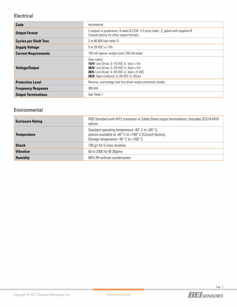
Shaft Bore 0.750”, 0.625”, 0.500”, 0.375. Diameters 0.625” and under are supplied with insulating sleeves.
Allowable Misalignment 0.005: T.I.R. on mating shaft 0.75” from shaft end
Bore Runout 0.001” T.I.R.
Starting Torque at 25°C 7 oz-in max. for Through shaft (SS) and 4 oz-in max. for Blind shaft (BS).
Bearings High precision ball bearings, Material: Chrome steel
Shaft Material 6061-T6 aluminum alloy
Bearing Housing Die cast aluminum with protective finish
Cover Die cast aluminum with protective finish
Bearing Life 7.5 X 10⁹ revolutions
Maximum RPM 6,000 RPM (see Frequency Response, below)
Moment of Inertia 17 X 10-4 oz-in-sec2
Weight 9 oz typical
| HS25 SERIESINCREMENTAL ENCODER
SPECIFICATIONS
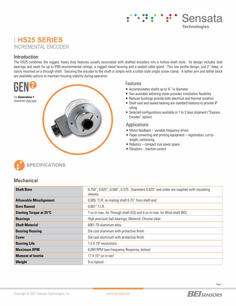
The HS25 combines the rugged, heavy duty features usually associated with shafted encoders into a hollow-shaft style. Its design includes dual bearings and seals for up to IP65 environmental ratings, a rugged metal housing and a sealed cable gland. This low profile design, just 2” deep, is easily mounted on a through shaft. Securing the encoder to the shaft is simple with a collet-style single screw clamp. A tether arm and tether block are available options to maintain housing stability during operation.
Introduction
Mechanical
Features
Applications
• Accommodates shafts up to ¾” in diameter.• Two available tethering styles provides installation flexibility• Reducer bushings provide both electrical and thermal isolation• Shaft seal and sealed bearing are standard features to provide IP
rating• Selected configurations available in 1 to 3 days shipment (“Express
Encoder” option)
• Motor feedback – variable frequency drives• Paper converting and printing equipment – registration, cut-to-
length, cartonizing• Robotics – compact size saves space• Elevators – traction control
For Generation 1datasheet click here.
www.sensata.com
Page 2
Copyright © 2021 Sensata Technologies, Inc.
Enclosure Rating IP65 Standard with M12 connector or Cable Gland output terminations. (Includes SCS18-M18 option)
TemperatureStandard operating temperature -40° C to +85° C; options available at -40° C to +100° C (Consult factory). Storage temperature -40° C to +100° C.
Shock 100 g’s for 5 msec duration
Vibration 50 to 2000 Hz @ 30grms
Humidity 98% RH without condensation
Environmental
Code Incremental
Output Format 2 outputs in quadrature, A leads B CCW, 1/2 cycle index , Z, gated with negative BConsult factory for other output formats.
Cycles per Shaft Turn 2 to 80,000 (see table 2)
Supply Voltage 5 to 28 VDC +/- 5%
Current Requirements 100 mA typical +output load, 250 mA (max)
Voltage/Output
(See notes)15/V: Line Driver, 5–15 VDC in, Vout = Vin28/V: Line Driver, 5–28 VDC in, Vout = Vin28/5: Line Driver, 5–28 VDC in, Vout = 5 VDC28/O: Open Collector, 5–28 VDC in, OCout
Protection Level Reverse, overvoltage and line driver output protection diodes
Frequency Response 300 kHz
Output Terminations See Table 1
Electrical

www.sensata.com
Page 3
Copyright © 2021 Sensata Technologies, Inc.
1.37 0.20
0.62
0.82
1.6
25
2.02 0.75100.7500 THRU
1.92
2.41
2.5
0
0.92
15°
4X#6-32X.25 MIN DPEQUALLY SPACED
STAINLESS STEEL SHAFT
0.43
SM12 OPTION
#8-32 HEX SOCKETCLAMP SCREW(9/64 IN. HEX)
2.43
HS25F-75-SS: .75 IN. THRU BORE(SM12 CONN. OPTION)
HS25F-75-SS: .75 IN. THRU BORE(SCS CABLE OPTION)
ALLOW FOR APPROX. 2 IN. CABLE BEND RADIUS BEYOND END OF CABLE GLAND
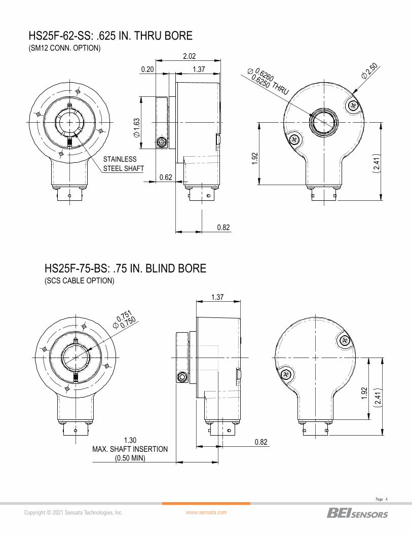
Dimensions in inches
DIMENSIONS
www.sensata.com
Page 4
Copyright © 2021 Sensata Technologies, Inc.
1.37 0.20
0.62
0.82
1.6
3
2.02 0.62600.6250 THRU
1.92
2.41
2.5
0
0.82
1.37
1.30MAX. SHAFT INSERTION
(0.50 MIN)
STAINLESS STEEL SHAFT
1.92
2.
41
0.751
0.750
HS25F-62-SS: .625 IN. THRU BORE(SM12 CONN. OPTION)
HS25F-75-BS: .75 IN. BLIND BORE(SCS CABLE OPTION)
www.sensata.com
Page 5
Copyright © 2021 Sensata Technologies, Inc.
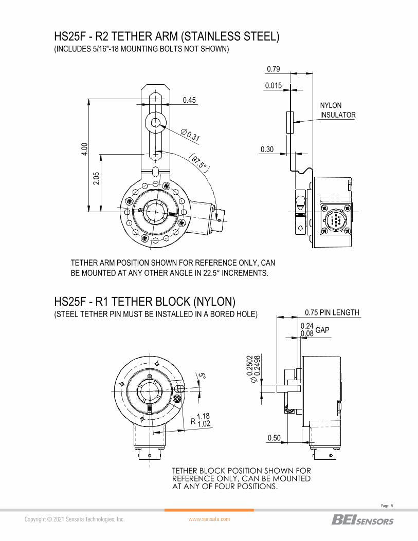
2.05
4.
00
0.45
0.31
97.5°
TETHER ARM POSITION SHOWN FOR REFERENCE ONLY, CAN BE MOUNTED AT ANY OTHER ANGLE IN 22.5° INCREMENTS.
5°
R 1.181.02
TETHER BLOCK POSITION SHOWN FOR REFERENCE ONLY, CAN BE MOUNTED AT ANY OF FOUR POSITIONS.
0.30
0.79
0.015
NYLON INSULATOR
0.240.08 GAP
0.75 PIN LENGTH
0.50
0.2
502
0.249
8
HS25F - R2 TETHER ARM (STAINLESS STEEL)(INCLUDES 5/16"-18 MOUNTING BOLTS NOT SHOWN)
HS25F - R1 TETHER BLOCK (NYLON)(STEEL TETHER PIN MUST BE INSTALLED IN A BORED HOLE)
www.sensata.com
Page 6
Copyright © 2021 Sensata Technologies, Inc.
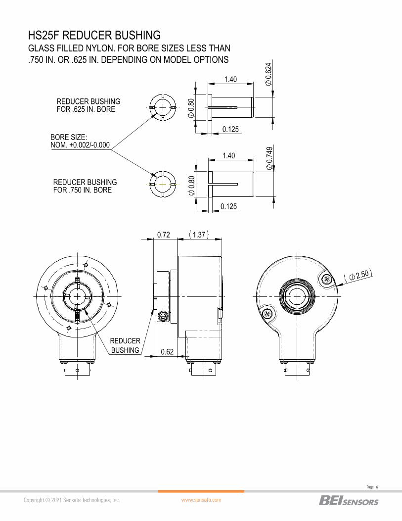
1.37
0.62
0.72
2.50
1.40
0.7
49
0.125
0.8
0
BORE SIZE:NOM. +0.002/-0.000
1.40 0.624
0.125
0.80
HS25F REDUCER BUSHINGGLASS FILLED NYLON. FOR BORE SIZES LESS THAN .750 IN. OR .625 IN. DEPENDING ON MODEL OPTIONS
REDUCER BUSHING FOR .625 IN. BORE
REDUCER BUSHING FOR .750 IN. BORE
REDUCER BUSHING
www.sensata.com
Page 7
Copyright © 2021 Sensata Technologies, Inc.
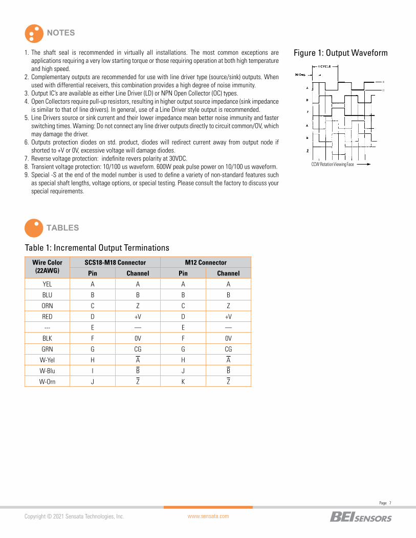
TABLES
Table 1: Incremental Output Terminations
Wire Color (22AWG)
SCS18-M18 Connector M12 Connector
Pin Channel Pin Channel
YEL A A A A
BLU B B B B
ORN C Z C Z
RED D +V D +V
--- E — E —
BLK F 0V F 0V
GRN G CG G CG
W-Yel H A H A
W-Blu I B J B
W-Orn J Z K Z
NOTES
Figure 1: Output Waveform
LO
CCW Rotation Viewing Face
HI
1. The shaft seal is recommended in virtually all installations. The most common exceptions are applications requiring a very low starting torque or those requiring operation at both high temperature and high speed.
2. Complementary outputs are recommended for use with line driver type (source/sink) outputs. When used with differential receivers, this combination provides a high degree of noise immunity.
3. Output IC’s are available as either Line Driver (LD) or NPN Open Collector (OC) types.4. Open Collectors require pull-up resistors, resulting in higher output source impedance (sink impedance
is similar to that of line drivers). In general, use of a Line Driver style output is recommended.5. Line Drivers source or sink current and their lower impedance mean better noise immunity and faster
switching times. Warning: Do not connect any line driver outputs directly to circuit common/OV, which may damage the driver.
6. Outputs protection diodes on std. product, diodes will redirect current away from output node if shorted to +V or 0V, excessive voltage will damage diodes.
7. Reverse voltage protection: indefinite revers polarity at 30VDC.8. Transient voltage protection: 10/100 us waveform. 600W peak pulse power on 10/100 us waveform.9. Special -S at the end of the model number is used to define a variety of non-standard features such
as special shaft lengths, voltage options, or special testing. Please consult the factory to discuss your special requirements.
www.sensata.com
Page 8
Copyright © 2021 Sensata Technologies, Inc.
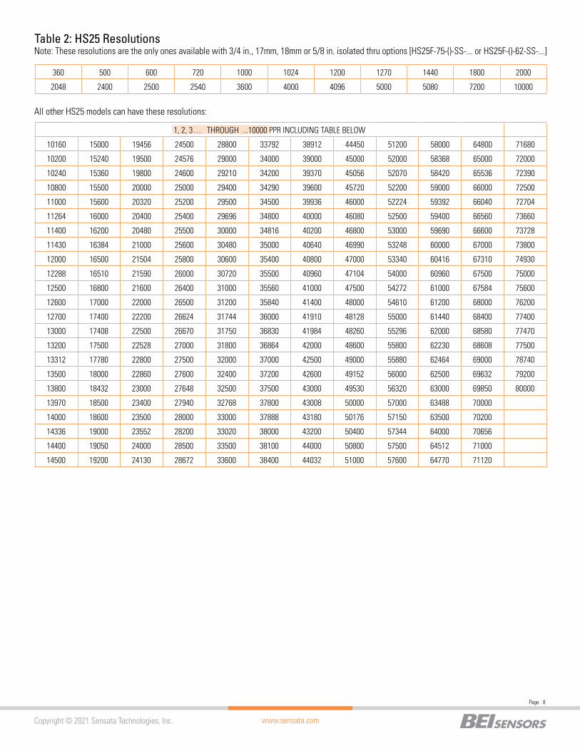
Note: These resolutions are the only ones available with 3/4 in., 17mm, 18mm or 5/8 in. isolated thru options [HS25F-75-()-SS-... or HS25F-()-62-SS-...]Table 2: HS25 Resolutions
360 500 600 720 1000 1024 1200 1270 1440 1800 2000
2048 2400 2500 2540 3600 4000 4096 5000 5080 7200 10000
All other HS25 models can have these resolutions:
1, 2, 3… THROUGH ...10000 PPR INCLUDING TABLE BELOW
10160 15000 19456 24500 28800 33792 38912 44450 51200 58000 64800 71680
10200 15240 19500 24576 29000 34000 39000 45000 52000 58368 65000 72000
10240 15360 19800 24600 29210 34200 39370 45056 52070 58420 65536 72390
10800 15500 20000 25000 29400 34290 39600 45720 52200 59000 66000 72500
11000 15600 20320 25200 29500 34500 39936 46000 52224 59392 66040 72704
11264 16000 20400 25400 29696 34800 40000 46080 52500 59400 66560 73660
11400 16200 20480 25500 30000 34816 40200 46800 53000 59690 66600 73728
11430 16384 21000 25600 30480 35000 40640 46990 53248 60000 67000 73800
12000 16500 21504 25800 30600 35400 40800 47000 53340 60416 67310 74930
12288 16510 21590 26000 30720 35500 40960 47104 54000 60960 67500 75000
12500 16800 21600 26400 31000 35560 41000 47500 54272 61000 67584 75600
12600 17000 22000 26500 31200 35840 41400 48000 54610 61200 68000 76200
12700 17400 22200 26624 31744 36000 41910 48128 55000 61440 68400 77400
13000 17408 22500 26670 31750 36830 41984 48260 55296 62000 68580 77470
13200 17500 22528 27000 31800 36864 42000 48600 55800 62230 68608 77500
13312 17780 22800 27500 32000 37000 42500 49000 55880 62464 69000 78740
13500 18000 22860 27600 32400 37200 42600 49152 56000 62500 69632 79200
13800 18432 23000 27648 32500 37500 43000 49530 56320 63000 69850 80000
13970 18500 23400 27940 32768 37800 43008 50000 57000 63488 70000
14000 18600 23500 28000 33000 37888 43180 50176 57150 63500 70200
14336 19000 23552 28200 33020 38000 43200 50400 57344 64000 70656
14400 19050 24000 28500 33500 38100 44000 50800 57500 64512 71000
14500 19200 24130 28672 33600 38400 44032 51000 57600 64770 71120
www.sensata.com
Page 9
Copyright © 2021 Sensata Technologies, Inc.
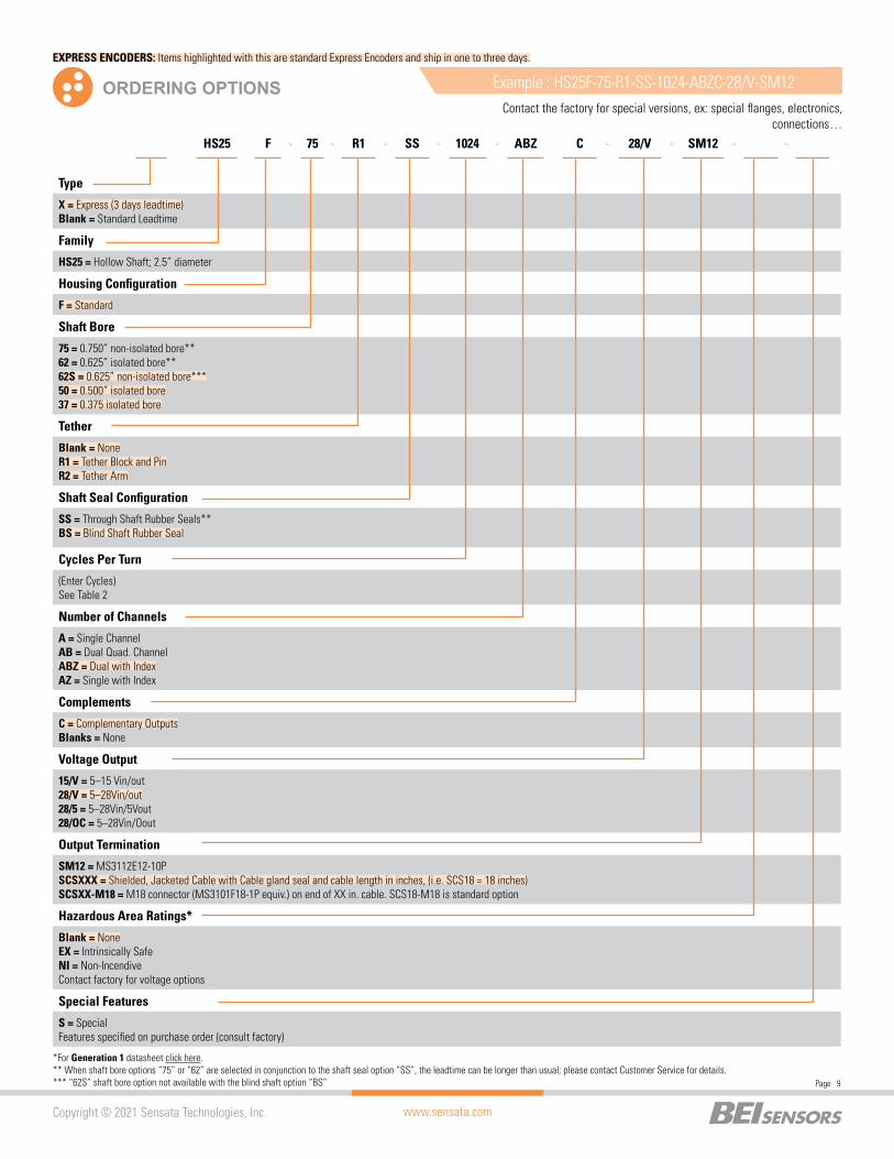
Type
X = Express (3 days leadtime)Blank = Standard Leadtime
Family
HS25 = Hollow Shaft; 2.5” diameter
Housing Configuration
F = Standard
Shaft Bore
75 = 0.750” non-isolated bore**62 = 0.625” isolated bore**62S = 0.625” non-isolated bore***50 = 0.500” isolated bore37 = 0.375 isolated bore
Tether
Blank = NoneR1 = Tether Block and PinR2 = Tether Arm
Shaft Seal Configuration
SS = Through Shaft Rubber Seals**BS = Blind Shaft Rubber Seal
Cycles Per Turn
(Enter Cycles)See Table 2
Number of Channels
A = Single ChannelAB = Dual Quad. ChannelABZ = Dual with IndexAZ = Single with Index
Complements
C = Complementary OutputsBlanks = None
Voltage Output
15/V = 5–15 Vin/out28/V = 5–28Vin/out28/5 = 5–28Vin/5Vout28/OC = 5–28Vin/Oout
Output Termination
SM12 = MS3112E12-10PSCSXXX = Shielded, Jacketed Cable with Cable gland seal and cable length in inches, (i.e. SCS18 = 18 inches)SCSXX-M18 = M18 connector (MS3101F18-1P equiv.) on end of XX in. cable. SCS18-M18 is standard option
Hazardous Area Ratings*
Blank = NoneEX = Intrinsically SafeNI = Non-IncendiveContact factory for voltage options
Special Features
S = SpecialFeatures specified on purchase order (consult factory)
ORDERING OPTIONS Example : HS25F-75-R1-SS-1024-ABZC-28/V-SM12Contact the factory for special versions, ex: special flanges, electronics,
connections…HS25 F - 75 - R1 - SS - 1024 - ABZ C - 28/V - SM12 - -
*For Generation 1 datasheet click here.** When shaft bore options “75” or “62” are selected in conjunction to the shaft seal option “SS”, the leadtime can be longer than usual; please contact Customer Service for details.*** “62S” shaft bore option not available with the blind shaft option “BS”
EXPRESS ENCODERS: Items highlighted with this are standard Express Encoders and ship in one to three days.
www.sensata.com
Page 10
Copyright © 2021 Sensata Technologies, Inc.
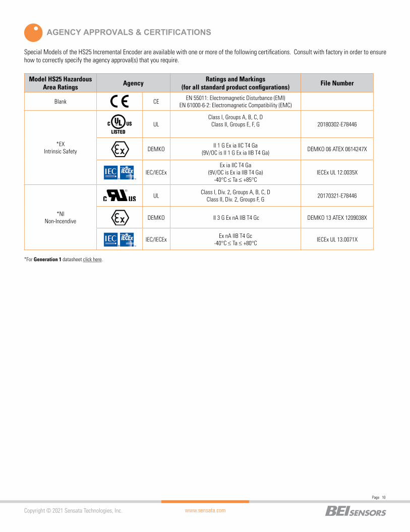
AGENCY APPROVALS & CERTIFICATIONS
Special Models of the HS25 Incremental Encoder are available with one or more of the following certifications. Consult with factory in order to ensure how to correctly specify the agency approval(s) that you require.
Model HS25 Hazardous Area Ratings Agency Ratings and Markings
(for all standard product configurations) File Number
Blank CE EN 55011: Electromagnetic Disturbance (EMI)EN 61000-6-2: Electromagnetic Compatibility (EMC)
*EX Intrinsic Safety
ULClass I, Groups A, B, C, D
Class II, Groups E, F, G 20180302-E78446
DEMKO II 1 G Ex ia IIC T4 Ga(9V/OC is II 1 G Ex ia IIB T4 Ga) DEMKO 06 ATEX 0614247X
IEC/IECExEx ia IIC T4 Ga
(9V/OC is Ex ia IIB T4 Ga)-40°C ≤ Ta ≤ +85°C
IECEx UL 12.0035X
*NI Non-Incendive
UL Class I, Div. 2, Groups A, B, C, DClass II, Div. 2, Groups F, G 20170321-E78446
DEMKO II 3 G Ex nA IIB T4 Gc DEMKO 13 ATEX 1209038X
IEC/IECEx Ex nA IIB T4 Gc-40°C ≤ Ta ≤ +80°C IECEx UL 13.0071X
*For Generation 1 datasheet click here.
www.sensata.com
Page 11
Copyright © 2021 Sensata Technologies, Inc.
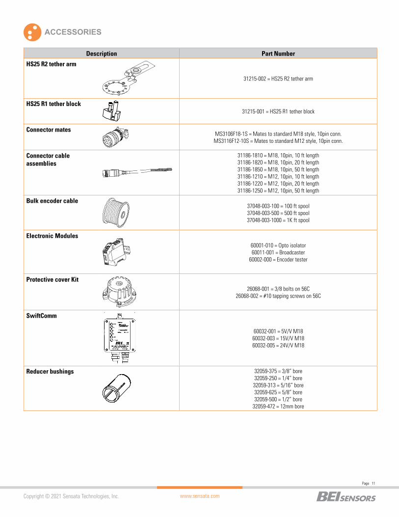
Description Part Number
HS25 R2 tether arm
31215-002 = HS25 R2 tether arm
HS25 R1 tether block31215-001 = HS25 R1 tether block
Connector matesMS3106F18-1S = Mates to standard M18 style, 10pin conn.MS3116F12-10S = Mates to standard M12 style, 10pin conn.
Connector cable assemblies
31186-1810 = M18, 10pin, 10 ft length31186-1820 = M18, 10pin, 20 ft length31186-1850 = M18, 10pin, 50 ft length31186-1210 = M12, 10pin, 10 ft length31186-1220 = M12, 10pin, 20 ft length31186-1250 = M12, 10pin, 50 ft length
Bulk encoder cable37048-003-100 = 100 ft spool37048-003-500 = 500 ft spool37048-003-1000 = 1K ft spool
Electronic Modules60001-010 = Opto isolator60011-001 = Broadcaster
60002-000 = Encoder tester
Protective cover Kit26068-001 = 3/8 bolts on 56C
26068-002 = #10 tapping screws on 56C
SwiftComm
THESE COMMODITIES, TECHNOLOGY OR SOFTWARE IF EXPORTED FROM THE UNITED STATES MUST BE IN ACCORDANCE WITH THE BUREAU OF INDUSTRY, EXPORT ADMINISTRATION REGULATIONS. DIVERSION CONTRARY TO U.S. LAW IS PROHIBITED
60032-001 = 5V/V M1860032-003 = 15V/V M1860032-005 = 24V/V M18
Reducer bushings 32059-375 = 3/8” bore32059-250 = 1/4” bore32059-313 = 5/16” bore32059-625 = 5/8” bore32059-500 = 1/2” bore
32059-472 = 12mm bore
ACCESSORIES
Page 12
www.sensata.com
CONTACT US
Americas+1 (800) 350 2727 – Option [email protected], Middle East & Africa+33 (3) 88 20 [email protected] [email protected] +86 (21) 2306 1500Japan +81 (45) 277 7117Korea +82 (31) 601 2004India +91 (80) 67920890Rest of Asia +886 (2) 27602006 ext 2808
Copyright © 2021 Sensata Technologies, Inc.
Sensata Technologies, Inc. (“Sensata”) data sheets are solely intended to assist designers (“Buyers”) who are developing systems that incorporate Sensata products (also referred to herein as “components”). Buyer understands and agrees that Buyer remains responsible for using its independent analysis, valuation, and judgment in designing Buyer’s systems and products. Sensata data sheets have been created using standard laboratory conditions and engineering practices. Sensata has not conducted any testing other than that specifically described in the published documentation for a particular data sheet. Sensata may make corrections, enhancements, improvements, and other changes to its data sheets or components without notice.Buyers are authorized to use Sensata data sheets with the Sensata component(s) identified in each particular data sheet. HOWEVER, NO OTHER LICENSE, EXPRESS OR IMPLIED, BY ESTOPPEL OTHERWISE TO ANY OTHER SENSATA INTELLECTUAL PROPERTY RIGHT, AND NO LICENSE TO ANY THIRD PARTY TECHNOLOGY OR INTELLECTUAL PROPERTY RIGHT, IS GRANTED HEREIN. SENSATA DATA SHEETS ARE PROVIDED “AS IS”. SENSATA MAKES NO WARRANTIES OR REPRESENTATIONS WITH REGARD TO THE DATA SHEETS OR USE OF THE DATA SHEETS, EXPRESS, IMPLIED, OR STATUTORY, INCLUDING ACCURACY OR COMPLETENESS. SENSATA DISCLAIMS ANY WARRANTY OF TITLE AND ANY IMPLIED WARRANTIES OF MERCHANTABILITY, FITNESS FOR A PARTICULAR PURPOSE, QUIET ENJOYMENT, QUIET POSSESSION, AND NON-INFRINGEMENT OF ANY THIRD PARTY INTELLECTUAL PROPERTY RIGHTS WITH REGARD TO SENSATA DATA SHEETS OR USE THEREOF.All products are sold subject to Sensata’s terms and conditions of sale supplied at www.sensata.com SENSATA ASSUMES NO LIABILITY FOR APPLICATIONS ASSISTANCE OR THE DESIGN OF BUYERS’ PRODUCTS. BUYER ACKNOWLEDGES AND AGREES THAT IT IS SOLELY RESPONSIBLE FOR COMPLIANCE WITH ALL LEGAL, REGULATORY, AND SAFETY-ELATED REQUIREMENTS CONCERNING ITS PRODUCTS, AND ANY USE OF SENSATA COMPONENTS IN ITS APPLICATIONS, NOTWITHSTANDING ANY APPLICATIONS-RELATED INFORMATION OR SUPPORT THAT MAY BE PROVIDED BY SENSATA.Mailing Address: Sensata Technologies, Inc., 529 Pleasant Street, Attleboro, MA 02703, USA
02352-001 REV 07/28/2021