Embed Size (px)
Citation preview

March 2006DEUTSCHE NORM
English price group 11No part of this translation may be reproduced without prior permission ofDIN Deutsches Institut für Normung e. V., Berlin. Beuth Verlag GmbH, 10772 Berlin, Germany,has the exclusive right of sale for German Standards (DIN-Normen).
ICS 21.120.10
!,z2Y"9871554
www.din.de
DDIN 5480-1
Involute splines based on reference diameters –
Part 1: General
Passverzahnungen mit Evolventenflanken und Bezugsdurchmesser –Teil 1: Grundlagen
©
SupersedesDIN 5480-1:1991-10 andDIN 5480-14:1986-03
www.beuth.de
In case of doubt, the German-language original should be consulted as the authoritative text.
Translation by DIN-Sprachendienst.
Document comprises 24 pages
Exe
mpl
ar p
ara
uso
excl
usiv
o -
Jaci
ara
Mat
ias
- 08
9.86
8.40
9-95
(P
edid
o 57
0643
Impr
esso
: 29/
07/2
019)
DIN 5480-1:2006-03
2
Contents Page
Foreword..............................................................................................................................................................4 1 Scope ......................................................................................................................................................5 2 Normative references ............................................................................................................................5 3 Symbols, designations and units.........................................................................................................6 4 Structure .................................................................................................................................................8 5 Preferred series of modules, reference diameters and number of teeth.........................................9 6 Basic rack profile .................................................................................................................................12 7 Diameters..............................................................................................................................................14 7.1 Diameters for side-fit splines .............................................................................................................14 7.2 7.2.1 General..................................................................................................................................................15 7.2.2 Major diameter fit splines ...................................................................................................................15 7.2.3 Minor diameter fit splines ...................................................................................................................16 8 Designation ..........................................................................................................................................17 9 Data to be shown on drawings...........................................................................................................18 9.1 Data field...............................................................................................................................................18 9.2 Indication of individual deviations.....................................................................................................18 9.3 Statistical actual tolerance limit (STA) ..............................................................................................18 9.4 Representation in drawings................................................................................................................19 10 Fit system for space width / tooth thickness....................................................................................19 10.1 General..................................................................................................................................................19 10.2 Structure of the tolerance system......................................................................................................19 10.3 Deviations.............................................................................................................................................20 10.4 Total tolerance TG ................................................................................................................................20 10.5 Actual tolerance Tact ............................................................................................................................20 10.6 Effective tolerance Teff.........................................................................................................................20 10.7 Design specifications..........................................................................................................................20 10.8 Calculation of tolerance limits............................................................................................................20 10.9 Deviations and tolerances ..................................................................................................................22 10.10 Guide values for radial runout............................................................................................................23 10.11 Fit types ................................................................................................................................................23 10.12 Quality assurance................................................................................................................................23 Bibliography ......................................................................................................................................................24
Diameters for diameter fit splines......................................................................................................15
Exe
mpl
ar p
ara
uso
excl
usiv
o -
Jaci
ara
Mat
ias
- 08
9.86
8.40
9-95
(P
edid
o 57
0643
Impr
esso
: 29/
07/2
019)
DIN 5480-1:2006-03
3
Figures Page
Figure 1 — Double teeth ....................................................................................................................................9 Figure 2 — Basic rack profile..........................................................................................................................12 Figure 3 — Bottom clearance of side-fit splines...........................................................................................15 Figure 4 — Major diameter fit ..........................................................................................................................16 Figure 5 — Minor diameter fit..........................................................................................................................16 Figure 6 — Example of a data field in a drawing...........................................................................................18 Figure 7 — Schematic diagram of space width / tooth thickness fit ..........................................................19
Tables
Table 1 — Preferred series, reference diameters dB from 6 mm to 58 mm ................................................10 Table 2 — Preferred series, reference diameters dB from 60 mm to 500 mm ............................................11 Table 3 — Basic rack profile ...........................................................................................................................13 Table 4 — Minimum form clearance ...............................................................................................................14 Table 5 — Recommended tolerances and deviations for tip and root diameters .....................................16 Table 6 — Calculation of tolerance limits ......................................................................................................21 Table 7 — Deviations and tolerances.............................................................................................................22 Table 8 — Guide values for radial runout ......................................................................................................23 Table 9 — Fit types...........................................................................................................................................23
See foreword for relationship to the ISO 4156 series of standards published by the International Organization for Standardization (ISO).
Exe
mpl
ar p
ara
uso
excl
usiv
o -
Jaci
ara
Mat
ias
- 08
9.86
8.40
9-95
(P
edid
o 57
0643
Impr
esso
: 29/
07/2
019)

DIN 5480-1:2006-03
4
Validity
This standard is valid from 2006-03-01.
Foreword
This series of standards deals with involute splines and spline joints within a module range of 0,5 to 10, having a number of teeth ranging from 6 to 82 and with a pressure angle of 30°. The DIN 5480 series of standards is limited to splines with a pressure angle of 30°, since pressure angles of 37,5° and 45° are covered by ISO 4156.
Involute splines in accordance with ISO 4156 are based on module series. These are not interchangeable with involute splines conforming to the DIN 5480 series of standards.
The DIN 5480 series of standards is based on reference diameters that are independent of the module, allowing an optimal fit to standard ball and roller bearing diameters and reducing the number of different tools required for manufacturing. This series of standards has been revised by Technical Committee 2.1 Passverzahnungen (“Involute splines”) of the Normenauschuss Maschinenbau (Mechanical Engineering Standards Committee). The revision was considered necessary since a review of the DIN 5480 series of standards in accordance with DIN 820-4 had shown that the series had structural and editorial weaknesses. The object of the revision was to combine the individual parts of this standard in a practical, sensible manner.
The entire series of standards now consists of only four parts instead of the previous sixteen.
DIN 5480 Involute splines based on reference diameters now comprises:
⎯ Part 1: General
⎯ Part 2: Nominal and inspection dimensions
⎯ Part 15: Inspection
⎯ Part 16: Tools
The new edition of DIN 5480-1 deals with fundamental principles, the same as its predecessor, but now also includes fit dimensions and tolerances, these being formerly contained in DIN 5480-14:1986-03. The calculation formulae, tolerances and deviations contained in Part 1 also apply to the other parts of this series of standards. DIN 5480-2 now contains the nominal dimensions and inspection dimensions for the range of items stated above, and incorporates the contents of the former editions of DIN 5480-2 to DIN 5480-13.
DIN 5480-15 covers quality inspections of spline joints.
DIN 5480-16 defines the design features of tools for manufacturing involute splines.
Amendments
This standard differs from DIN 5480-1:1991-10 and DIN 5480-14:1986-03 as follows:
a) The title has been changed to “Involute splines based on reference diameters”.
b) The full root radius has been included for shafts.
c) Cold-rolling has been included as a manufacturing process for shafts.
d) The standard has been editorially revised.
e) The entire contents of DIN 5480-14:1986-03 have been integrated into DIN 5480-1.
Exe
mpl
ar p
ara
uso
excl
usiv
o -
Jaci
ara
Mat
ias
- 08
9.86
8.40
9-95
(P
edid
o 57
0643
Impr
esso
: 29/
07/2
019)
DIN 5480-1:2006-03
5
Previous editions
DIN 5480-1: 1966-12, 1974-09, 1986-03, 1991-10
DIN 5480-14: 1966-12, 1974-09, 1986-03
1 Scope
This standard applies to involute splines and spline joints based on reference diameters for connecting hubs and shafts either with a removable connection, a sliding fit or a permanent fit. It lays down the following general characteristics for splines as in this standard:
a) They have a standard pressure angle of 30°.
b) The basic rack profile is the same for all pitches, therefore applying a uniform design rule to all profiles.
c) They have a side fit profile (a diameter fit is permitted in some cases).
d) Addendum modification is used in order to achieve specific reference diameters.
e) The fit system includes tolerances for effective form deviations so that the effect of such deviations on backlash is taken into account. The specified range of fundamental deviations and tolerance classes takes due consideration of all requirements.
2 Normative references
The following referenced documents are indispensable for the application of this document. For dated references, only the edition cited applies. For undated references, the latest edition of the referenced document (including any amendments) applies.
DIN 323-1, Preferred numbers and series of preferred numbers — Basic values, calculated values, rounded values
DIN 780-1, Series of modules for gears — Modules for spur gears
DIN 3960, Definitions, parameters and equations for involute cylindrical gears and gear pairs
DIN 5466-1, Splined joints, calculation of load capacity — Part 1: General
DIN 5480-2, Involute splines based on reference diameters — Part 2: Nominal dimensions and inspection dimensions
DIN 5480-15, Involute splines based on reference diameters — Part 15: Quality inspection
DIN 5480-16, Involute splines based on reference diameters — Part 16: Tools
DIN ISO 6413, Technical drawings — Representation of splines and serrations
Exe
mpl
ar p
ara
uso
excl
usiv
o -
Jaci
ara
Mat
ias
- 08
9.86
8.40
9-95
(P
edid
o 57
0643
Impr
esso
: 29/
07/2
019)
DIN 5480-1:2006-03
6
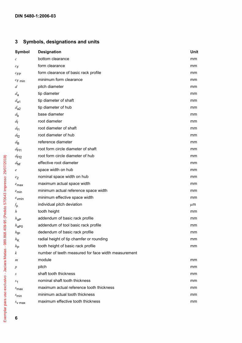
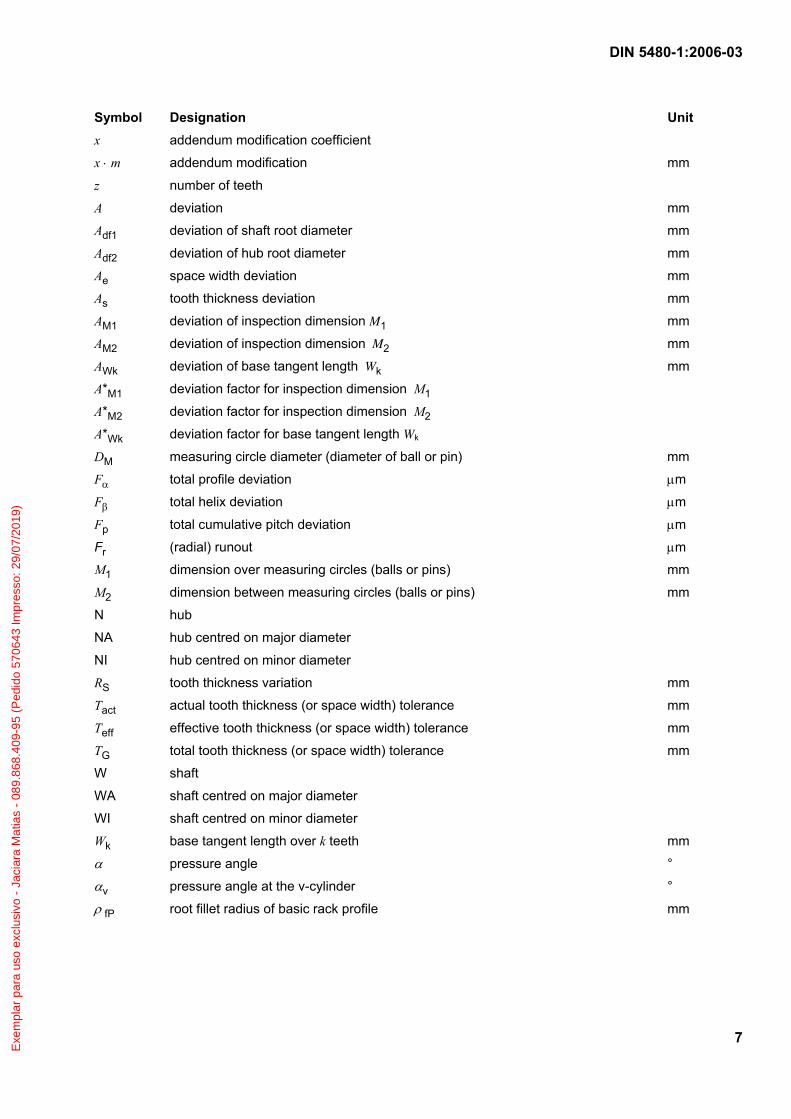
3 Symbols, designations and units
Symbol Designation Unit c bottom clearance mm
cF form clearance mm
cFP form clearance of basic rack profile mm
cF min minimum form clearance mm
d pitch diameter mm
da tip diameter mm
da1 tip diameter of shaft mm
da2 tip diameter of hub mm
db base diameter mm
df root diameter mm
df1 root diameter of shaft mm
df2 root diameter of hub mm
dB reference diameter mm
dFf1 root form circle diameter of shaft mm
dFf2 root form circle diameter of hub mm
dNf effective root diameter mm
e space width on hub mm
e2 nominal space width on hub mm
emax maximum actual space width mm
emin minimum actual reference space width mm
evmin minimum effective space width mm
fp individual pitch deviation μm
h tooth height mm
haP addendum of basic rack profile mm
haP0 addendum of tool basic rack profile mm
hfP dedendum of basic rack profile mm
hK radial height of tip chamfer or rounding mm
hP tooth height of basic rack profile mm
k number of teeth measured for face width measurement
m module mm
p pitch mm
s shaft tooth thickness mm
s1 nominal shaft tooth thickness mm
smax maximum actual reference tooth thickness mm
smin minimum actual tooth thickness mm
sv max maximum effective tooth thickness mm
Exe
mpl
ar p
ara
uso
excl
usiv
o -
Jaci
ara
Mat
ias
- 08
9.86
8.40
9-95
(P
edid
o 57
0643
Impr
esso
: 29/
07/2
019)
DIN 5480-1:2006-03
7
Symbol Designation Unit x addendum modification coefficient
x ⋅ m addendum modification mm
z number of teeth
A deviation mm
Adf1 deviation of shaft root diameter mm
Adf2 deviation of hub root diameter mm
Ae space width deviation mm
As tooth thickness deviation mm
AM1 deviation of inspection dimension M1 mm
AM2 deviation of inspection dimension M2 mm
AWk deviation of base tangent length Wk mm
A*M1 deviation factor for inspection dimension M1
A*M2 deviation factor for inspection dimension M2
A*Wk deviation factor for base tangent length Wk
DM measuring circle diameter (diameter of ball or pin) mm
Fα total profile deviation μm
Fβ total helix deviation μm
Fp total cumulative pitch deviation μm
Fr (radial) runout μm
M1 dimension over measuring circles (balls or pins) mm
M2 dimension between measuring circles (balls or pins) mm
N hub
NA hub centred on major diameter
NI hub centred on minor diameter
RS tooth thickness variation mm
Tact actual tooth thickness (or space width) tolerance mm
Teff effective tooth thickness (or space width) tolerance mm
TG total tooth thickness (or space width) tolerance mm
W shaft
WA shaft centred on major diameter
WI shaft centred on minor diameter
Wk base tangent length over k teeth mm
α pressure angle °
αv pressure angle at the v-cylinder °
ρ fP root fillet radius of basic rack profile mm
Exe
mpl
ar p
ara
uso
excl
usiv
o -
Jaci
ara
Mat
ias
- 08
9.86
8.40
9-95
(P
edid
o 57
0643
Impr
esso
: 29/
07/2
019)

DIN 5480-1:2006-03
8
Subscript Refers to Subscript Refers to Subscript Refers to
a tooth tip G total 0 tool
e space width K tip chamfer 1 shaft
f root of tooth N effective diameter 2 hub
s tooth thickness P basic rack profile * deviation factor
v effective tolerance limit act actual
F form diameter eff effective
4 Structure
The tooth interlock of a splined joint is determined by the basic rack profile, the reference diameter, the module and the number of teeth. The selection of nominal dimensions is essentially determined by the following condition: The shaft cross-section remaining available for transmitting torques shall not be reduced more than is necessary to permit easy slip-fitting of components such as, for instance, ball or roller bearings. In joints centred on any pitch diameter, this condition is met by making the reference diameter equal to the bore of the bearing and then modifying the profiles of the teeth of the hub and the shaft accordingly.
The number of teeth shall be selected in such a way that the addendum modification necessitated by the reference diameter is kept within the range x1 ⋅ m = –0,05 ⋅ m to +0,45 ⋅ m. The mean pressure angle on the v-cylinder ranges from 30° to more than 40°.
Even numbers of teeth are given preference in Tables 1 and 2. The reasons for this are explained in subclause 7.2.
Values of –0,05 ⋅ m and +0,45 ⋅ m are specified as limits for the nominal addendum modification of shafts; the limits for the nominal addendum modification of hubs are specified as +0,05 ⋅ m and –0,45 ⋅ m. Exceptions (x1 >+ 0,45) have been permitted for some larger numbers of teeth (z1 ≥ 60) in order to enable even numbers of teeth to be produced and to avoid using prime numbers, since the effect of the addendum modifications on the pressure angle on the v-cylinder αv decreases as the number of teeth increases.
Depending on the reference diameter, calculations for the number of teeth for Tables 1 and 2 using the formulae given in Table 3 will result either in a number teeth with an addendum modification that is within the specified limits or in two consecutive numbers of teeth with equal limit values x1 = –0,05 and +0,45, since this addendum modification range of 0,5 ⋅ m corresponds to a difference of one tooth. In such cases, the maximum value of the addendum modification (x1 = +0,45) is taken for splines where z < 10, and the even number of teeth is taken where z ≥ 10 to facilitate the production of double teeth on shafts or hubs, which means that the addendum modification can also assume the minimum value (x1 = –0,05). Figure 1 shows a major diameter fit shaft with splines. The double spaces of the associated hub or of a minor diameter fit shaft cannot be measured using balls or pins; rather, GO and NO GO gauges are required.
Exe
mpl
ar p
ara
uso
excl
usiv
o -
Jaci
ara
Mat
ias
- 08
9.86
8.40
9-95
(P
edid
o 57
0643
Impr
esso
: 29/
07/2
019)

DIN 5480-1:2006-03
9
Figure 1 — Double teeth
If the number of spaces which can be measured using pins is an odd number, then the measurements given in the Tables can be converted.
M1,2 = (M1,2Tabelle – DM) ⋅ cos(π/(2 ⋅ z)) + DM (1)
A*M1,2 = A*
M1,2Tabelle ⋅ cos(π/(2 ⋅ z)) (2)
(π is the angle in radians)
In keeping with the rule defined in DIN 3960, M2 must be a negative value. The symbol z then represents the new odd number of spaces.
A number of teeth expressed as 6 (12) indicates six double teeth out of a total of 12:
EXAMPLE DIN 5480 – WA 17 × 1,25 × 6 (12) × h6 × 9e
5 Preferred series of modules, reference diameters and number of teeth
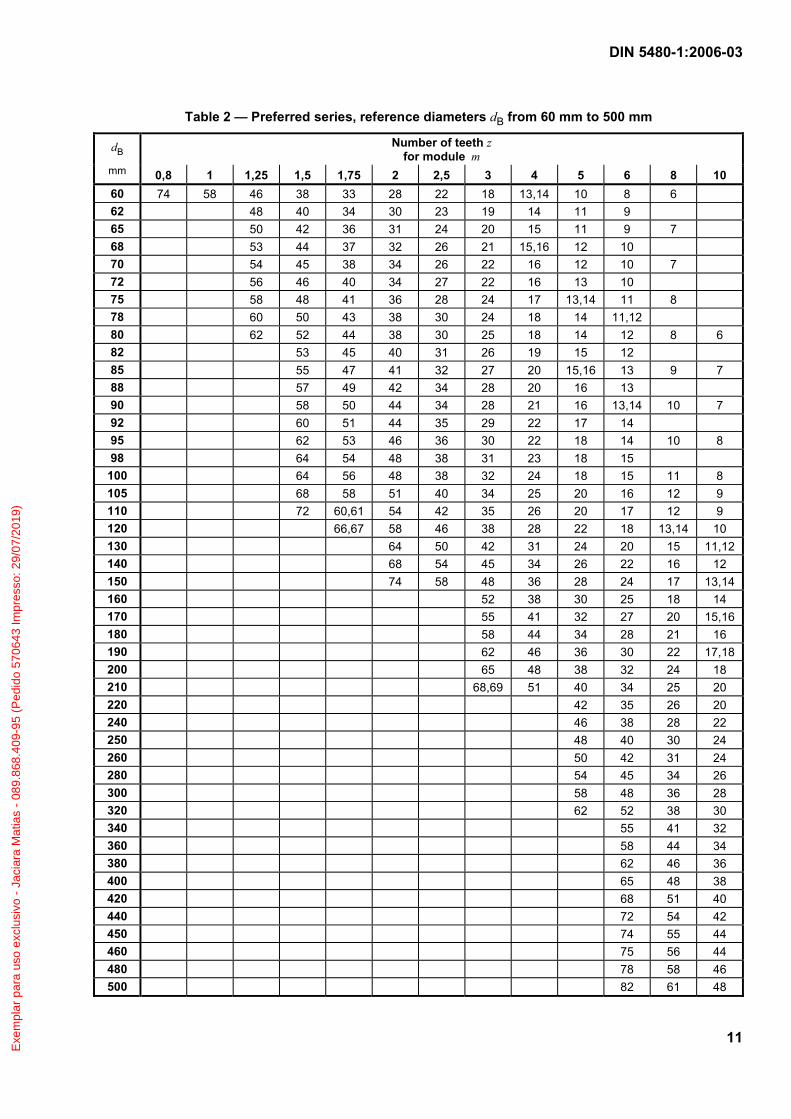
This standard provides for a large selection of splines. The module series correspond to the module series I and II as defined in DIN 780-1 and the metric module series as defined in ISO 54:1977.
Exe
mpl
ar p
ara
uso
excl
usiv
o -
Jaci
ara
Mat
ias
- 08
9.86
8.40
9-95
(P
edid
o 57
0643
Impr
esso
: 29/
07/2
019)

DIN 5480-1:2006-03
10
Table 1 — Preferred series, reference diameters dB from 6 mm to 58 mm
Number of teeth z for module m
dB
mm 0,5 0,6 0,75 0,8 1 1,25 1,5 1,75 2 2,5 3 4 5 6 6 10 8 6 6 7 12 10 8 7 8 14 12 9 8 6 9 16 13 10 10 7
10 18 15 12 11 8 6 11 20 17 13 12 9 7 12 22 18 14 13 10 8 6 13 24 20 16 15 11 9 7 6 14 26 22 17 16 12 10 8 6 15 28 23 18 17 13 10 8 7 6 16 30 25 20 18 14 11 9 8 6 17 32 27 21 20 15 12 10 8 7 18 34 28 22 21 16 13 10 9 7 19 36 30 24 22 17 14 11 9 20 38 32 25 23,24 18 14 12 10 8 6 21 40 34 26 25 19 15 12 10 22 42 35 28 26 20 16 13 11 9 7 6 23 44 37 29 27 22 17 14 12 24 46 38 30 28 22 18 14 12 25 48 40 32 30 24 18 15 13 11 8 7 26 50 42 33 31 24 19 16 13 27 52 44 34 32 26 20 16 14 28 54 45 36 34 26 21 17 14 12 10 8 29 56 47 37 35 28 22 18 15 30 58 48 38 36 28 22 18 16 13,14 10 8 31 60 50 40 37 30 23 19 16 32 62 52 41 38 30 24 20 17 14 11 9 6 33 64 54 42 40 32 25 20 17 34 66 55 44 41 32 26 21 18 35 68 57 45 42 34 26 22 18 16 12 10 7 36 70 58 46 44 34 27 22 19 37 72 60 48 45 36 28 23 20 17 13 11 8 38 74 62 49 46 36 29 24 20 18 14 11 8 39 76 64 50 47 38 30 24 21 40 78 64 52 48 38 30 25 21 18 14 12 8 6 42 68 54 51 40 32 26 22 20 15 12 9 7 45 74 58 55 44 34 28 24 21 16 13,14 10 7 47 76 60 57 46 36 30 25 22 17 14 10 8 48 78 62 58 46 37 30 26 22 18 14 10 8 6 50 64 60 48 38 32 27 24 18 15 11 9 7 52 68 64 50 40 33 28 24 19 16 11 9 7 55 72 66 54 42 35 30 26 20 17 12 9 8 58 70 56 45 37 32 28 22 18 13 10 8
Exe
mpl
ar p
ara
uso
excl
usiv
o -
Jaci
ara
Mat
ias
- 08
9.86
8.40
9-95
(P
edid
o 57
0643
Impr
esso
: 29/
07/2
019)
DIN 5480-1:2006-03
11
Table 2 — Preferred series, reference diameters dB from 60 mm to 500 mm
Number of teeth z for module m
dB
mm 0,8 1 1,25 1,5 1,75 2 2,5 3 4 5 6 8 10 60 74 58 46 38 33 28 22 18 13,14 10 8 6 62 48 40 34 30 23 19 14 11 9 65 50 42 36 31 24 20 15 11 9 7 68 53 44 37 32 26 21 15,16 12 10 70 54 45 38 34 26 22 16 12 10 7 72 56 46 40 34 27 22 16 13 10 75 58 48 41 36 28 24 17 13,14 11 8 78 60 50 43 38 30 24 18 14 11,12 80 62 52 44 38 30 25 18 14 12 8 6 82 53 45 40 31 26 19 15 12 85 55 47 41 32 27 20 15,16 13 9 7 88 57 49 42 34 28 20 16 13 90 58 50 44 34 28 21 16 13,14 10 7 92 60 51 44 35 29 22 17 14 95 62 53 46 36 30 22 18 14 10 8 98 64 54 48 38 31 23 18 15
100 64 56 48 38 32 24 18 15 11 8 105 68 58 51 40 34 25 20 16 12 9 110 72 60,61 54 42 35 26 20 17 12 9 120 66,67 58 46 38 28 22 18 13,14 10 130 64 50 42 31 24 20 15 11,12 140 68 54 45 34 26 22 16 12 150 74 58 48 36 28 24 17 13,14 160 52 38 30 25 18 14 170 55 41 32 27 20 15,16 180 58 44 34 28 21 16 190 62 46 36 30 22 17,18 200 65 48 38 32 24 18 210 68,69 51 40 34 25 20 220 42 35 26 20 240 46 38 28 22 250 48 40 30 24 260 50 42 31 24 280 54 45 34 26 300 58 48 36 28 320 62 52 38 30 340 55 41 32 360 58 44 34 380 62 46 36 400 65 48 38 420 68 51 40 440 72 54 42 450 74 55 44 460 75 56 44 480 78 58 46 500 82 61 48
Exe
mpl
ar p
ara
uso
excl
usiv
o -
Jaci
ara
Mat
ias
- 08
9.86
8.40
9-95
(P
edid
o 57
0643
Impr
esso
: 29/
07/2
019)

DIN 5480-1:2006-03
12
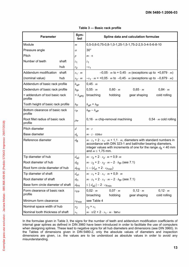
6 Basic rack profile
Figure 2 shows the basic rack profile. The corresponding descriptive parameters, tooth interlock data and calculation formulae are given in Table 3.
Key
1 Shaft 2 Hub 3 Profile reference line
Figure 2 — Basic rack profile
Exe
mpl
ar p
ara
uso
excl
usiv
o -
Jaci
ara
Mat
ias
- 08
9.86
8.40
9-95
(P
edid
o 57
0643
Impr
esso
: 29/
07/2
019)
DIN 5480-1:2006-03
13
Table 3 — Basic rack profile
Parameter Sym-bol Spline data and calculation formulae
Module m 0,5-0,6-0,75-0,8-1,0-1,25-1,5-1,75-2-2,5-3-4-5-6-8-10
Pressure angle α 30°
Pitch p m ⋅ π
Number of teeth shaft z1 z1
hub z2 –z1
Addendum modification shaft x1 ⋅ m –0,05 ⋅ m to + 0,45 ⋅ m (exceptions up to +0,879 ⋅ m)
(nominal value) hub x2 ⋅ m –x1 ⋅ m = +0,05 ⋅ m to –0,45 ⋅ m (exceptions up to –0,879 ⋅ m)
Addendum of basic rack profile haP 0,45 ⋅ m
Dedendum of basic rack profile hfP 0,55 ⋅ m 0,60 ⋅ m 0,65 ⋅ m 0,84 ⋅ m
= addendum of tool basic rack profile
= haP0 broaching hobbing gear shaping cold rolling
Tooth height of basic rack profile hP haP + hfP
Bottom clearance of basic rack profile
cP hfP – haP
Root fillet radius of basic rack profile
ρfP 0,16 ⋅ m chip-removal machining 0,54 ⋅ m cold rolling
Pitch diameter d m ⋅ z
Base diameter db m ⋅ z ⋅ cosα
Reference diameter dB m ⋅ z1 + 2 ⋅ x1 ⋅ m + 1,1 ⋅ m, diameters with standard numbers in accordance with DIN 323-1 and ball/roller bearing diameters, integer values with increments of one for the range dB < 40 mm and m ≤ 1,75 mm.
Tip diameter of hub da2 m ⋅ z2 + 2 ⋅ x2 ⋅ m + 0,9 ⋅m
Root diameter of hub df2 m ⋅ z2 + 2 ⋅ x2 ⋅ m – 2 ⋅ hfP (see 7.1)
Root form circle diameter of hub dFf2 ≤ – (da1 + 2 ⋅ cFmin)
Tip diameter of shaft da1 m ⋅ z1 + 2 ⋅ x1 ⋅ m + 0,9 ⋅ m
Root diameter of shaft df1 m ⋅ z1 + 2 ⋅ x1 ⋅ m – 2 ⋅ hfP (see 7.1)
Base form circle diameter of shaft dFf1 ≤ | da2 | – 2 ⋅ cFmin
Form clearance of basic rack profile
cFP 0,02 ⋅ m 0,07 ⋅ m 0,12 ⋅ m 0,12 ⋅ m broaching hobbing gear shaping cold rolling
Minimum form clearance cFmin see Table 4
Nominal space width of hub e2 e2 = s1
Nominal tooth thickness of shaft s1 m ⋅ π/2 + 2 ⋅ x1 ⋅ m ⋅ tanα
In the formulae given in Table 3, the signs for the number of teeth and addendum modification coefficients of internal gear splines as defined in DIN 3960 have been introduced in order to facilitate the use of computers when designing splines. These lead to negative signs for all hub diameters and dimensions (see DIN 3960). In the Tables of dimensions given in DIN 5480-2, only the absolute values of diameters and inspection dimensions are given, i.e. the values are to be understood as absolute values in order to avoid any misunderstanding.
Exe
mpl
ar p
ara
uso
excl
usiv
o -
Jaci
ara
Mat
ias
- 08
9.86
8.40
9-95
(P
edid
o 57
0643
Impr
esso
: 29/
07/2
019)
DIN 5480-1:2006-03
14
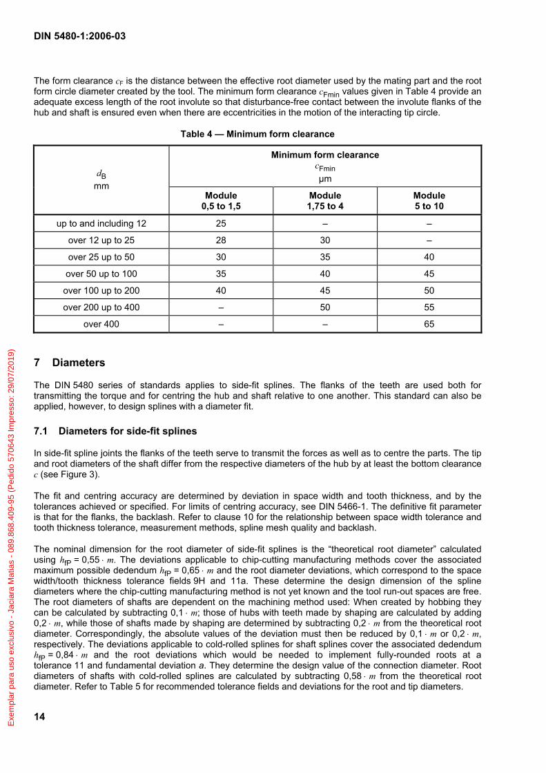
The form clearance cF is the distance between the effective root diameter used by the mating part and the root form circle diameter created by the tool. The minimum form clearance cFmin values given in Table 4 provide an adequate excess length of the root involute so that disturbance-free contact between the involute flanks of the hub and shaft is ensured even when there are eccentricities in the motion of the interacting tip circle.
Table 4 — Minimum form clearance
Minimum form clearance cFmin µm dB
mm Module
0,5 to 1,5 Module 1,75 to 4
Module 5 to 10
up to and including 12 25 – –
over 12 up to 25 28 30 –
over 25 up to 50 30 35 40
over 50 up to 100 35 40 45
over 100 up to 200 40 45 50
over 200 up to 400 – 50 55
over 400 – – 65
7 Diameters
The DIN 5480 series of standards applies to side-fit splines. The flanks of the teeth are used both for transmitting the torque and for centring the hub and shaft relative to one another. This standard can also be applied, however, to design splines with a diameter fit.
7.1 Diameters for side-fit splines
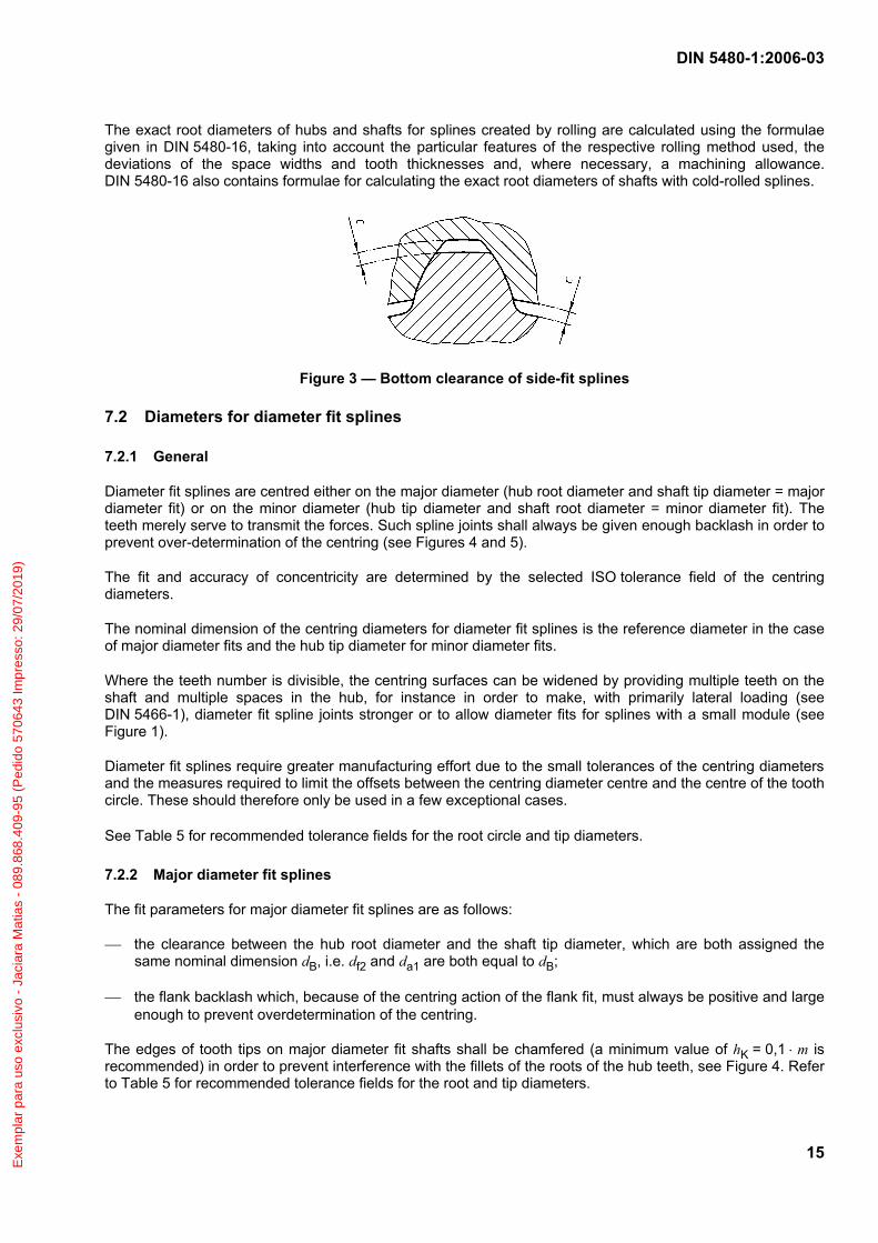
In side-fit spline joints the flanks of the teeth serve to transmit the forces as well as to centre the parts. The tip and root diameters of the shaft differ from the respective diameters of the hub by at least the bottom clearance c (see Figure 3).
The fit and centring accuracy are determined by deviation in space width and tooth thickness, and by the tolerances achieved or specified. For limits of centring accuracy, see DIN 5466-1. The definitive fit parameter is that for the flanks, the backlash. Refer to clause 10 for the relationship between space width tolerance and tooth thickness tolerance, measurement methods, spline mesh quality and backlash.
The nominal dimension for the root diameter of side-fit splines is the “theoretical root diameter” calculated using hfP = 0,55 ⋅ m. The deviations applicable to chip-cutting manufacturing methods cover the associated maximum possible dedendum hfP = 0,65 ⋅ m and the root diameter deviations, which correspond to the space width/tooth thickness tolerance fields 9H and 11a. These determine the design dimension of the spline diameters where the chip-cutting manufacturing method is not yet known and the tool run-out spaces are free. The root diameters of shafts are dependent on the machining method used: When created by hobbing they can be calculated by subtracting 0,1 ⋅ m; those of hubs with teeth made by shaping are calculated by adding 0,2 ⋅ m, while those of shafts made by shaping are determined by subtracting 0,2 ⋅ m from the theoretical root diameter. Correspondingly, the absolute values of the deviation must then be reduced by 0,1 ⋅ m or 0,2 ⋅ m, respectively. The deviations applicable to cold-rolled splines for shaft splines cover the associated dedendum hfP = 0,84 ⋅ m and the root deviations which would be needed to implement fully-rounded roots at a tolerance 11 and fundamental deviation a. They determine the design value of the connection diameter. Root diameters of shafts with cold-rolled splines are calculated by subtracting 0,58 ⋅ m from the theoretical root diameter. Refer to Table 5 for recommended tolerance fields and deviations for the root and tip diameters.
Exe
mpl
ar p
ara
uso
excl
usiv
o -
Jaci
ara
Mat
ias
- 08
9.86
8.40
9-95
(P
edid
o 57
0643
Impr
esso
: 29/
07/2
019)
DIN 5480-1:2006-03
15
The exact root diameters of hubs and shafts for splines created by rolling are calculated using the formulae given in DIN 5480-16, taking into account the particular features of the respective rolling method used, the deviations of the space widths and tooth thicknesses and, where necessary, a machining allowance. DIN 5480-16 also contains formulae for calculating the exact root diameters of shafts with cold-rolled splines.
Figure 3 — Bottom clearance of side-fit splines
7.2 Diameters for diameter fit splines
7.2.1 General
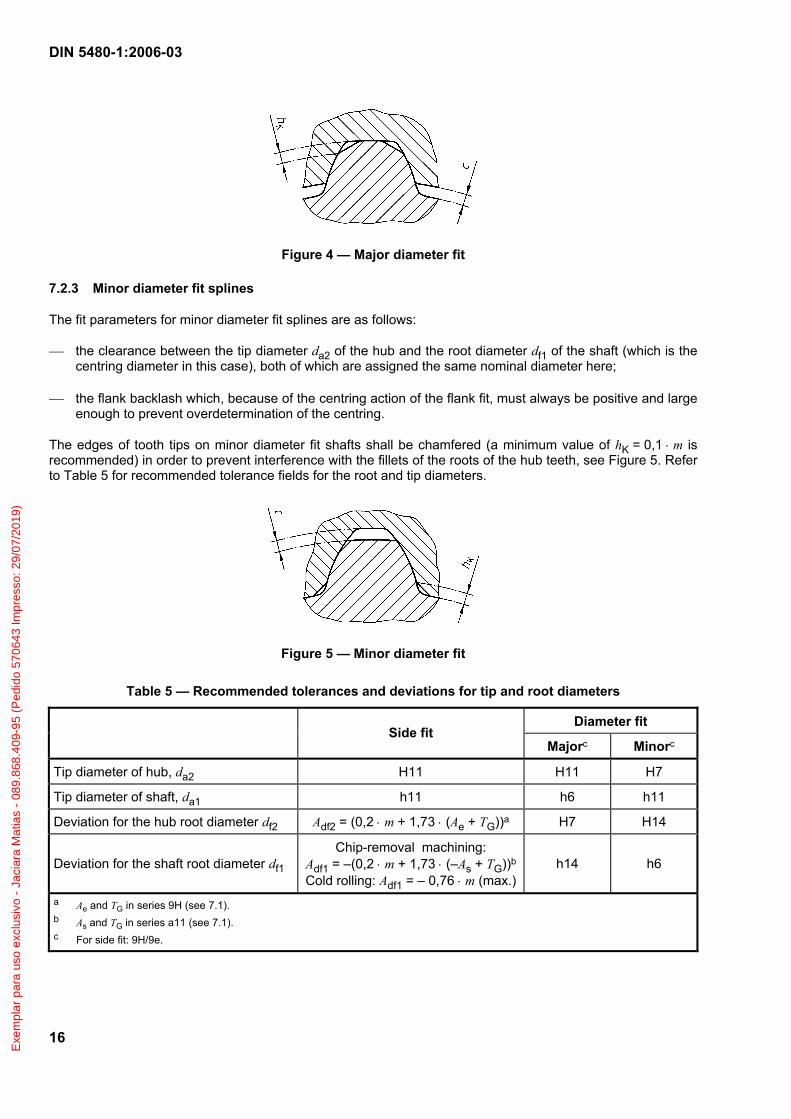
Diameter fit splines are centred either on the major diameter (hub root diameter and shaft tip diameter = major diameter fit) or on the minor diameter (hub tip diameter and shaft root diameter = minor diameter fit). The teeth merely serve to transmit the forces. Such spline joints shall always be given enough backlash in order to prevent over-determination of the centring (see Figures 4 and 5).
The fit and accuracy of concentricity are determined by the selected ISO tolerance field of the centring diameters.
The nominal dimension of the centring diameters for diameter fit splines is the reference diameter in the case of major diameter fits and the hub tip diameter for minor diameter fits.
Where the teeth number is divisible, the centring surfaces can be widened by providing multiple teeth on the shaft and multiple spaces in the hub, for instance in order to make, with primarily lateral loading (see DIN 5466-1), diameter fit spline joints stronger or to allow diameter fits for splines with a small module (see Figure 1).
Diameter fit splines require greater manufacturing effort due to the small tolerances of the centring diameters and the measures required to limit the offsets between the centring diameter centre and the centre of the tooth circle. These should therefore only be used in a few exceptional cases.
See Table 5 for recommended tolerance fields for the root circle and tip diameters.
7.2.2 Major diameter fit splines
The fit parameters for major diameter fit splines are as follows:
⎯ the clearance between the hub root diameter and the shaft tip diameter, which are both assigned the same nominal dimension dB, i.e. df2 and da1 are both equal to dB;
⎯ the flank backlash which, because of the centring action of the flank fit, must always be positive and large enough to prevent overdetermination of the centring.
The edges of tooth tips on major diameter fit shafts shall be chamfered (a minimum value of hK = 0,1 ⋅ m is recommended) in order to prevent interference with the fillets of the roots of the hub teeth, see Figure 4. Refer to Table 5 for recommended tolerance fields for the root and tip diameters.
Exe
mpl
ar p
ara
uso
excl
usiv
o -
Jaci
ara
Mat
ias
- 08
9.86
8.40
9-95
(P
edid
o 57
0643
Impr
esso
: 29/
07/2
019)
DIN 5480-1:2006-03
16
Figure 4 — Major diameter fit
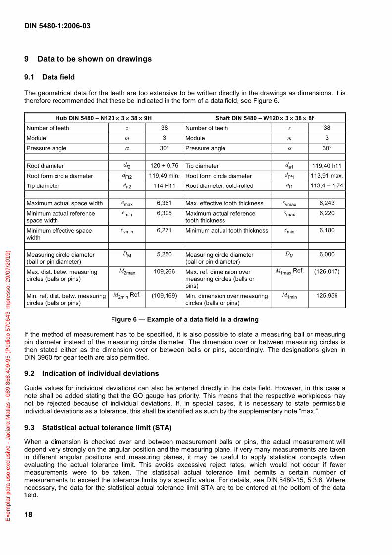
7.2.3 Minor diameter fit splines
The fit parameters for minor diameter fit splines are as follows:
⎯ the clearance between the tip diameter da2 of the hub and the root diameter df1 of the shaft (which is the centring diameter in this case), both of which are assigned the same nominal diameter here;
⎯ the flank backlash which, because of the centring action of the flank fit, must always be positive and large enough to prevent overdetermination of the centring.
The edges of tooth tips on minor diameter fit shafts shall be chamfered (a minimum value of hK = 0,1 ⋅ m is recommended) in order to prevent interference with the fillets of the roots of the hub teeth, see Figure 5. Refer to Table 5 for recommended tolerance fields for the root and tip diameters.
Figure 5 — Minor diameter fit
Table 5 — Recommended tolerances and deviations for tip and root diameters
Diameter fit Side fit
Majorc Minorc
Tip diameter of hub, da2 H11 H11 H7
Tip diameter of shaft, da1 h11 h6 h11
Deviation for the hub root diameter df2 Adf2 = (0,2 ⋅ m + 1,73 ⋅ (Ae + TG))a H7 H14
Deviation for the shaft root diameter df1 Chip-removal machining:
Adf1 = –(0,2 ⋅ m + 1,73 ⋅ (–As + TG))b
Cold rolling: Adf1 = – 0,76 ⋅ m (max.) h14 h6
a Ae and TG in series 9H (see 7.1). b As and TG in series a11 (see 7.1). c For side fit: 9H/9e.
Exe
mpl
ar p
ara
uso
excl
usiv
o -
Jaci
ara
Mat
ias
- 08
9.86
8.40
9-95
(P
edid
o 57
0643
Impr
esso
: 29/
07/2
019)

DIN 5480-1:2006-03
17
8 Designation
Splines as in this standard shall be designated by the main standard number (i.e. DIN 5480), an N for a hub or W for a shaft, followed by an A for major diameter fit or an I for minor diameter fit (only in the case of diameter fitting), then by the reference diameter, the module, the number of teeth, the tolerance class and the fundamental deviation. For diameter fit splines, the tolerance class and fundamental deviation shall be placed in front of the respective data of the tooth flanks.
EXAMPLE 1
Designation of a side fit spline joint
Reference diameter dB 120 mm Module m 3 mm Number of teeth z 38 Side fit 9H 8f
Spline joint DIN 5480 – 120 × 3 × 38 × 9H 8f Hub DIN 5480 – N 120 x 3 × 38 × 9H
Shaft DIN 5480 – W 120 × 3 × 38 × 8f
EXAMPLE 2
Designation of a major diameter fit spline joint
Reference diameter dB 120 mm Module m 3 mm Number of teeth z 38 Side fit 9H 9e Diameter fit H7 h6
Spline joint DIN 5480 – A 120 × 3 × 38 × H7 h6 × 9H 9e Hub DIN 5480 – NA 120 × 3 × 38 × H7 × 9H
Shaft DIN 5480 – WA 120 × 3 × 38 × h6 × 9e
EXAMPLE 3
Designation of a major diameter fit spline joint with double teeth on the shaft
Reference diameter dB 120 mm Module m 3 mm Number of teeth z 38 Side fit 9H 9e Diameter fit H7 h6
Spline joint DIN 5480 – A 120 × 3 × 19 (38) × H7 h6 × 9H 9e Hub DIN 5480 – NA 120 × 3 × 19 (38) × H7 × 9H
Shaft DIN 5480 – WA 120 × 3 × 19 (38) × h6 × 9e
EXAMPLE 4
Designation of a minor diameter fit spline joint
Reference diameter dB 120 mm Module m 3 mm Number of teeth z 38 Side fit 9H 9e Diameter fit H7 h6
Spline joint DIN 5480 – I 120 × 3 × 38 × H7 h6 × 9H 9e Hub DIN 5480 – NI 120 × 3 × 38 × H7 × 9H
Shaft DIN 5480 – WI 120 × 3 × 38 × h6 × 9e
Exe
mpl
ar p
ara
uso
excl
usiv
o -
Jaci
ara
Mat
ias
- 08
9.86
8.40
9-95
(P
edid
o 57
0643
Impr
esso
: 29/
07/2
019)
DIN 5480-1:2006-03
18
9 Data to be shown on drawings
9.1 Data field
The geometrical data for the teeth are too extensive to be written directly in the drawings as dimensions. It is therefore recommended that these be indicated in the form of a data field, see Figure 6.
Hub DIN 5480 – N120 × 3 × 38 × 9H Shaft DIN 5480 – W120 × 3 × 38 × 8f
Number of teeth z 38 Number of teeth z 38
Module m 3 Module m 3
Pressure angle α 30° Pressure angle α 30° Root diameter df2 120 + 0,76 Tip diameter da1 119,40 h11
Root form circle diameter dFf2 119,49 min. Root form circle diameter dFf1 113,91 max.
Tip diameter da2 114 H11 Root diameter, cold-rolled df1 113,4 – 1,74 Maximum actual space width emax 6,361 Max. effective tooth thickness svmax 6,243
Minimum actual reference space width
emin 6,305 Maximum actual reference tooth thickness
smax 6,220
Minimum effective space width
evmin 6,271 Minimum actual tooth thickness smin 6,180
Measuring circle diameter (ball or pin diameter)
DM 5,250 Measuring circle diameter (ball or pin diameter)
DM 6,000
Max. dist. betw. measuring circles (balls or pins)
M2max 109,266 Max. ref. dimension over measuring circles (balls or pins)
M1max Ref. (126,017)
Min. ref. dist. betw. measuring circles (balls or pins)
M2min Ref. (109,169) Min. dimension over measuring circles (balls or pins)
M1min 125,956
Figure 6 — Example of a data field in a drawing
If the method of measurement has to be specified, it is also possible to state a measuring ball or measuring pin diameter instead of the measuring circle diameter. The dimension over or between measuring circles is then stated either as the dimension over or between balls or pins, accordingly. The designations given in DIN 3960 for gear teeth are also permitted.
9.2 Indication of individual deviations
Guide values for individual deviations can also be entered directly in the data field. However, in this case a note shall be added stating that the GO gauge has priority. This means that the respective workpieces may not be rejected because of individual deviations. If, in special cases, it is necessary to state permissible individual deviations as a tolerance, this shall be identified as such by the supplementary note “max.”.
9.3 Statistical actual tolerance limit (STA)
When a dimension is checked over and between measurement balls or pins, the actual measurement will depend very strongly on the angular position and the measuring plane. If very many measurements are taken in different angular positions and measuring planes, it may be useful to apply statistical concepts when evaluating the actual tolerance limit. This avoids excessive reject rates, which would not occur if fewer measurements were to be taken. The statistical actual tolerance limit permits a certain number of measurements to exceed the tolerance limits by a specific value. For details, see DIN 5480-15, 5.3.6. Where necessary, the data for the statistical actual tolerance limit STA are to be entered at the bottom of the data field.
Exe
mpl
ar p
ara
uso
excl
usiv
o -
Jaci
ara
Mat
ias
- 08
9.86
8.40
9-95
(P
edid
o 57
0643
Impr
esso
: 29/
07/2
019)
DIN 5480-1:2006-03
19
9.4 Representation in drawings
DIN ISO 6413 specifies how splines are to be represented in drawings.
10 Fit system for space width / tooth thickness
10.1 General
The tooth flanks of splines are used both for transmitting the torque and for centring the hub and shaft relative to one another. The difference between the space width and the tooth thickness determines the rotational backlash. This standard specifies deviation series and tolerances for space widths of hubs and tooth thicknesses of shafts, which are based on the nominal dimensions, see Figure 7. The deviation series permits the definition of fit types (interference, transition, clearance). The tolerance classes define the manufacturing tolerances.
Figure 7 — Schematic diagram of space width / tooth thickness fit
10.2 Structure of the tolerance system
The tolerance system for splines as in this standard is based on the minimum theoretical clearance. A design clearance of zero ensures that the hub can be fitted on the shaft. For a minimum clearance of zero, it is better to set the effective tolerance limits to the dimension of the nominal space width e2 and the nominal tooth thickness s1.
Exe
mpl
ar p
ara
uso
excl
usiv
o -
Jaci
ara
Mat
ias
- 08
9.86
8.40
9-95
(P
edid
o 57
0643
Impr
esso
: 29/
07/2
019)

DIN 5480-1:2006-03
20
10.3 Deviations
Both positive and negative minimum clearances can be designed using the space width deviation Ae and the tooth thickness deviation As. The deviations for hubs are designated by upper case letters and those for shafts are designated by lower case letters; see Table 9. There are six deviations, from F to M for hubs and 18 deviations from v to a for shafts.
10.4 Total tolerance TG
The maximum theoretical clearance is determined by adding the deviations and the tolerance values of the total tolerances TG for the hub and the shaft. The total tolerance combines the actual tolerance and the effective tolerance. Eight tolerance grades are specified for hubs and shafts, determining the total tolerance as well as the actual and effective individual tolerances. These have a predefined interrelationship. In practice, the size of the actual tolerance Tact in relationship to the effective tolerance Teff within the total tolerance TG varies greatly. A ratio of TG/Tact ≈ 1,6 has been chosen in this standard as this seemed to be most suitable. If it is necessary to change the size ratio, then the actual tolerances and the effective tolerances as stated in this standard can be selected separately from the different tolerance grades and will, when added, lead to a total tolerance deviating from this standard.
10.5 Actual tolerance Tact
The actual tolerance allows for the effects of wear on tool dimensions, the infeed accuracy of machine tools and dimensional deviations due to heat treatment. In the data field of the workpiece drawing, it is given as the actual tolerance limit and as the reference mark actual Ref. Since it is difficult to measure tooth thickness and space widths directly, they shall be converted to dimensions across and between measuring circles and are entered in this form into the data field. In practice, measuring balls or measuring pins are used as measuring circles. The manufacturing tolerance should be at least twice the expected tooth thickness variation Rs.
10.6 Effective tolerance Teff
The effective tolerance is specified separately for splines as in this standard. This is necessary because the fit is generated over all left and right flanks of all teeth. The flanks of the teeth are subject to individual deviations due to the profile, the helix and the pitch. These deviations reduce the clearance of spline joints so severely that provision must be made for this effect. In hubs, the superposition of all individual deviations leads to an effective space width that is smaller than the actual space that can be measured. In shafts, the superposition of all individual deviations lead to an effective tooth thickness that is greater than the actual thickness which can be measured.
10.7 Design specifications
When designing splines as in this standard, the maximum and minimum permissible clearance are to be defined in the technical specifications. Given these values, it is the designer’s task to select the deviations and tolerance classes. A certain amount of experience is needed in selecting deviations and tolerances suitable for practical applications.
10.8 Calculation of tolerance limits
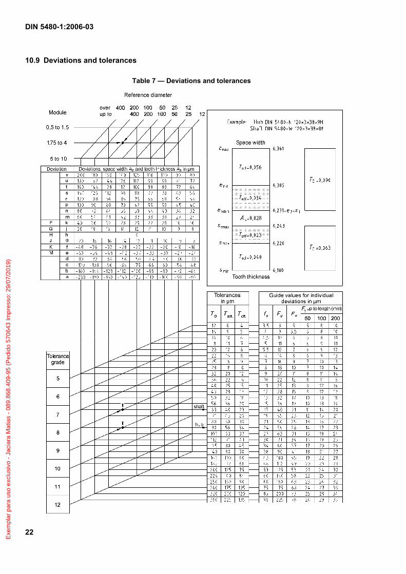
Tolerance limits are to be calculated on the basis of the nominal space width e2 of the hub and the tooth thickness s1 of the shaft, using the formulae given in Table 6. The deviations Ae and As as well as the tolerances Tact and Teff for the relevant tolerance grade are to be taken from Table 7.
Exe
mpl
ar p
ara
uso
excl
usiv
o -
Jaci
ara
Mat
ias
- 08
9.86
8.40
9-95
(P
edid
o 57
0643
Impr
esso
: 29/
07/2
019)
DIN 5480-1:2006-03
21
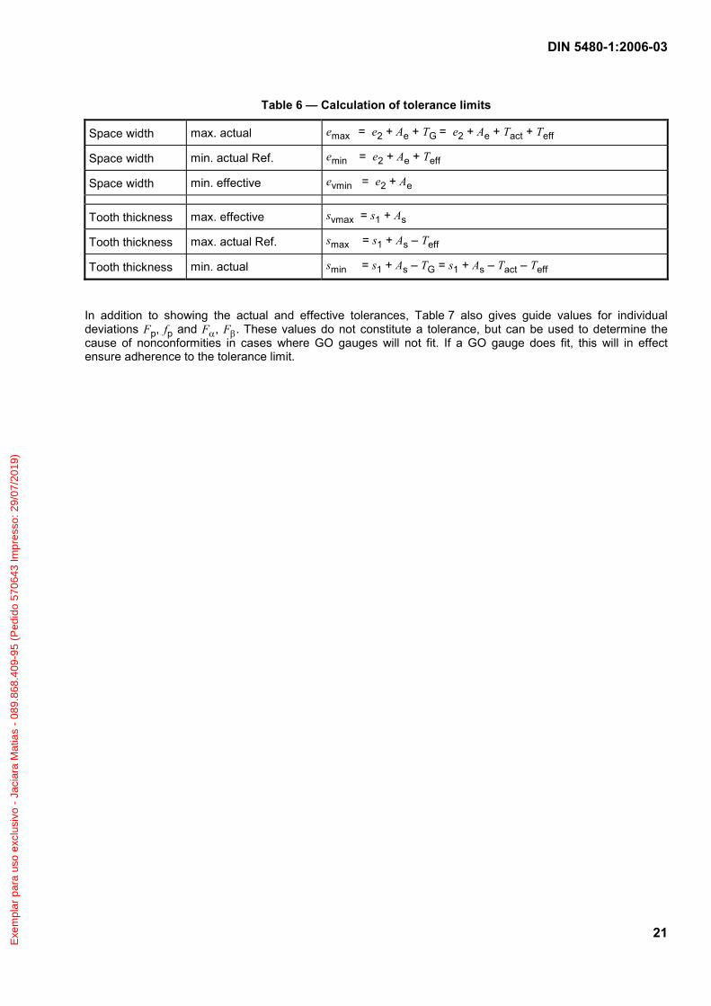
Table 6 — Calculation of tolerance limits
Space width max. actual emax = e2 + Ae + TG = e2 + Ae + Tact + Teff
Space width min. actual Ref. emin = e2 + Ae + Teff
Space width min. effective evmin = e2 + Ae
Tooth thickness max. effective svmax = s1 + As
Tooth thickness max. actual Ref. smax = s1 + As – Teff
Tooth thickness min. actual smin = s1 + As – TG = s1 + As – Tact – Teff
In addition to showing the actual and effective tolerances, Table 7 also gives guide values for individual deviations Fp, fp and Fα, Fβ. These values do not constitute a tolerance, but can be used to determine the cause of nonconformities in cases where GO gauges will not fit. If a GO gauge does fit, this will in effect ensure adherence to the tolerance limit.
Exe
mpl
ar p
ara
uso
excl
usiv
o -
Jaci
ara
Mat
ias
- 08
9.86
8.40
9-95
(P
edid
o 57
0643
Impr
esso
: 29/
07/2
019)
DIN 5480-1:2006-03
22
10.9 Deviations and tolerances
Table 7 — Deviations and tolerances
Exe
mpl
ar p
ara
uso
excl
usiv
o -
Jaci
ara
Mat
ias
- 08
9.86
8.40
9-95
(P
edid
o 57
0643
Impr
esso
: 29/
07/2
019)
DIN 5480-1:2006-03
23
10.10 Guide values for radial runout
As radial runout is largely a deviation of position and is specified relative to other geometrical elements, it is not possible to specify guide values for this parameter. Table 8 gives guideline values for the radial runout of the pitch diameter of external splines relative to a reference axis.
Table 8 — Guideline values for radial runout
Pitch diameter d
mm
Radial runout Fr μm
< 18 20
18 to < 30 30
30 to < 50 40
50 to < 100 50
100 to < 200 60
200 to < 500 80
10.11 Fit types
The deviations and tolerances given in Table 9 can be used to achieve a specific fit tpye (interference, transition or clearance).
Table 9 — Fit types
Deviations/tolerances Fit type
Hub Shaft
Rough interference fit 9H 9v
Precision interference fit 7H 8H 7p 8s
Rough transition fit 9H 9p
Precision transition fit 7H 8H 7m 8n
Rough clearance fit 9H 9g 9e 9d 10c 11a
Precision clearance fit 7H 8H 7h 7g 8f
10.12 Quality assurance
Quality assurance is described in DIN 5480-15. Compliance with the effective tolerance limit is to be checked using a composite GO gauge. Actual tolerance limits shall be checked with the aid of the auxiliary dimensions over and between measuring circles (using measuring balls or pins), or alternatively using sector NO GO gauges. The method of calculating the inspection dimensions over and between measuring circles from the dimensions of the space widths and the tooth thicknesses is described in DIN 5480-15, 5.2.4.3. As an alternative, this can also be done using the deviation factors as described in DIN 5480-2.
Deviation of the measurements between/over measuring circles:
AM2 = Ae × A*M2 (3)
AM1 = As × A*M1 (4)
Exe
mpl
ar p
ara
uso
excl
usiv
o -
Jaci
ara
Mat
ias
- 08
9.86
8.40
9-95
(P
edid
o 57
0643
Impr
esso
: 29/
07/2
019)

DIN 5480-1:2006-03
24
Bibliography
DIN 3961, Tolerances for cylindrical gear teeth — Principles
DIN 3977:1981-02, Measuring element diameters for the radial or diametral dimension for testing tooth thickness of cylindrical gears
DIN ISO 6413:1990-03, Technical drawings — Representation of splines and serrations (ISO 6413:1988)
ISO 54:1996, Cylindrical gears for general engineering and for heavy engineering — Modules
ISO 4156 series, Straight cylindrical involute splines — Metric module, side fit
Exe
mpl
ar p
ara
uso
excl
usiv
o -
Jaci
ara
Mat
ias
- 08
9.86
8.40
9-95
(P
edid
o 57
0643
Impr
esso
: 29/
07/2
019)


![No. 426.— IX.] ouble l]d](https://img.dokumen.tips/doc/110x75/62498f94d6763647af46db82/no-426-ix-ouble-ld.jpg)