Embed Size (px)
Citation preview

2016 IEEE International Embedded Vision Workshop
Award for Best Paper to
A Diverse Low Cost High Performance Platform for Advanced Driver Assistance System (ADAS) Applications
Prashanth Viswanath, Pramod Swami, Mihir Mody, Kedar Chitnis, Sujith Shivalingappa, Soyeb Nagori, Manu Mathew,
Kumar Desappan, Shyam Jagannathan, Deepak Poddar, Anshu Jain, Hrushikesh Garud, Vikram Appia, Mayank Mangla, Shashank Dabral
Stefano Mattoccia, Jagadeesh Sankaran Martin Humenberger, Swarup Medasani
July 2016
EVW 2016 General Chairs EVW 2016 Program Chairs
一款针对先进驾驶员辅助系统 (ADAS) 的多用途高性能平台
Prashanth ViswanathKedar ChitnisPramod SwamiMihir ModySujith ShivalingappaSoyeb NagoriManu MathewKumar DesappanShyam JagannathanDeepak PoddarAnshu JainHrushikesh GarudVikram AppiaMayank ManglaShashank Dabral
德州仪器 (TI)

A diverse high-performance platform for 2 October 2016 Advanced Driver Assistance System (ADAS) applications
Overview
Advanced driver assistance systems (ADAS) are becoming increasingly popular. ADAS applications such as lane departure warning (LDW), forward collision warning (FCW), automatic cruise control (ACC), auto emergency braking (AEB) and surround view (SV) that were present only in luxury vehicles in the past have trickled down to entry- and mid-level vehicles. Many of these applications are also mandated by safety authorities such as European New Car Assessment Program (Euro NCAP) and National Highway Traffic Safety Administration (NHTSA). In order to make these applications affordable in entry- and mid-level vehicles, it is important to have a cost-effective, yet high-performance and low-power solution. Texas Instruments (TI’s) TDA3x is an ideal platform to address these needs. In this paper we will illustrate the mapping of multiple algorithms such as SV, LDW, object detection (OD), structure from motion (SFM) and camera-monitor systems (CMS) to the TDA3x device, thereby demonstrating its computing capabilities. We also share the performance for these embedded vision applications, showing that TDA3x is an excellent high-performance device for ADAS applications.
1. Introduction
In the automotive space, the demand for ADAS
technology has increased as mobility has come
to be a basic need in today’s life. Approximately
1.25 million people died in road accidents around
the globe in 2013[2]. Pedestrians, cyclists and
motorcyclists comprise half of the road traffic
deaths, and motor vehicle crashes are ranked
number nine among top ten leading causes of death
in the world[5]. These statistics push automobile
manufacturers to ensure higher safety standards in
their vehicles. The European New Car Assessment
Program (Euro NCAP) and National Highway Traffic
Safety Administration (NHTSA) provide safety
ratings to new cars based on the safety systems
that are in place. Euro NCAP[6] provides better star
rating for cars equipped with AEB, FCA, LKA and
other ADAS applications, which ensures higher
safety for on-road vehicles, pedestrians, cyclists
and motorcyclists.
ADAS applications can be based upon various
sensor systems such as radar, camera, LiDAR
and ultrasound[7]. They can also integrate and
use external information sources such as global
positioning systems, car data networks and
vehicle-to-vehicle or vehicle-to-infrastructure
communication systems to efficiently and
accurately achieve desired goals. While different
sensor modalities have varying performance
based on different environmental conditions and
applications, camera sensors are emerging as a
key differentiator by car manufacturers. Camera-
based ADAS systems use various computer vision
(CV) technologies to perform real-time driving
situation analysis and provide warning to the driver.
The advantages of camera-based ADAS include
reliability and robustness under difficult real life
scenarios, and ability to support multiple varied
applications such as traffic sign recognition (TSR),
traffic light detection, lane and obstacle detection.
概述
过去只出现在豪华轿车上的先进驾驶员辅助系统 (ADAS) 正在变得越来越受青睐。诸如车
道偏离报警 (LDW)、前方碰撞报警 (FCW)、自动巡航控制 (ACC)、自动紧急刹车 (AEB) 和全景环视 (SV) 等 ADAS 应用已经逐渐走向入门级和中级车辆。这些应用中的很多应用也
是欧洲新车安全评鉴协会(Euro NCAP)和美国公路交通安全管理局 (NHTSA) 等安全部
门强制要求的功能。为了使这些应用在价格方面可被入门级和中级车所接收,拥有一款低
成本、而又具有高性能和低功耗的解决方案是十分必要的。德州仪器 (TI) 的 TDA3x 是一
个很好满足这些需求的理想平台。在这篇文章中,我们将用图示的方法给出 SV、LDW、
物体侦测 (OD)、运动恢复结构 (SFM) 和相机反光镜系统 (CMS) 等多个算法与 TDA3x 器
件的对应关系,从而展示出这款器件的计算能力。我们还会与您分享这些嵌入式视觉应用
的性能,从而让您了解到 TDA3x 是一款针对 ADAS 应用的出色、高性能器件。
1. 简介
随着移动性已经成为当前生活的一项基本
需求,汽车应用领域对 ADAS 技术的需要
越来越多。2013 年,全球范围内,死于路
面交通事故的人数将近 125 万人 [2]。行人、
自行车手、摩托车手占到了路面交通事故
死亡人数的一半,而在全世界十大致死原
因中,机动车碰撞排在第九位 [5]。这些统
计数据要求汽车厂商确保他们的车辆具有
更高的安全标准。欧洲新车安全评鉴协会
(Euro NCAP)和美国公路交通安全管理
局 (NHTSA) 根据当地车辆所具有的安全系
统来评定新车的安全等级。Euro NCAP[6] 将配备有 AEB、FCA、LKA 和其它 ADAS应用的汽车评定为更高的星级,这样就更
好地保证了路面车辆、行人、自行车手和
摩托车手的安全。
ADAS 应用可以基于雷达、摄像头、LiDAR和超声波等不同的传感器系统 [7]。ADAS 应
用还可以集成和使用全球定位系统、甚至
依托汽车内数据网络,车辆与车辆或车辆
与基础通信网络的通信来高效和准确地实
现所需要的目标。在不同的环境条件下和
不同的应用中,不同的传感器各有千秋,
新兴的摄像头传感器正在成为车厂实现差
异化的重要方面。基于摄像头的 ADAS 系
统使用不同的计算机视觉 (CV) 技术来执行
实时驾驶情况分析,并向驾驶员发出警报。
基于摄像头的 ADAS 的优势是在真实使用
环境下的可靠性和稳健耐用性,以及能够
支持交通标志识别 (TSR)、信号灯检测、车
道和障碍物检测等多个不同应用的能力。
为了实现 ADAS 的不同应用,基于摄像头
的系统被部署在前视、后视和环视视野中[8]。前方摄像头系统用于 AEB 和 FCW 等应
一款针对先进驾驶员辅助系统 (ADAS) 应用的多用途平台
2 2016 年 10 月

A diverse high-performance platform for 3 October 2016 Advanced Driver Assistance System (ADAS) applications
To enable different safety aspects of ADAS, camera-
based systems are deployed in front, back and
surround view[8]. The front camera systems are
used for applications such as AEB and FCW. The
rear view and surround view systems are used
for park assist and cross traffic alert applications.
Front camera systems can use mono or stereo
camera setup. Stereo camera is useful to obtain
3-D information by generating disparity. However,
stereo camera systems are more expensive
compared to mono camera systems. Structure
from Motion (SFM) technology[17] [11], which enables
a single moving camera to obtain depth, is being
widely researched for its capabilities in ADAS
applications. Surround view systems use multiple
cameras (four to six) placed around the car. The
feed from multiple cameras are re-mapped and
stitched to provide a 360-degree view to the driver.
Also, analytics are performed on these images to
alert the driver. Recently, Camera Mirror Systems
(CMS) are increasingly replacing mirrors in mid-/
high-end cars. In CMS systems the side and rear
view mirrors are replaced by cameras, and the
camera feed is displayed to the driver via display
panels (typically OLED display panels). Cameras
with wide angle field of view can reduce the number
of blind spots for the driver. Sophisticated features
like wide dynamic range (WDR)[15] and noise filter
allow the system to be used in variety of lighting
conditions including low-light, high-glare scenarios.
Due to the low surface area of the camera lens
versus a conventional mirror, a CMS system is less
susceptible to the effects of dust and rain. CMS
systems also have added advantage of reducing
wind drag and thus aiding fuel efficiency. Finally, the
CMS opens the possibility of running vision analytics
on them[12]. Figure 1 shows the flow for different
ADAS applications.
In order to fully utilize the capabilities of camera-
based systems for multiple applications, it is
imperative to have a high-performance, low-
power embedded processor that is capable of
analyzing data from multiple cameras in real time.
In order to solve this problem, Texas Instruments
Figure 1: Flow chart of ADAS applications
Image sensor Imaging subsystem
Multi-resolution representation
Feature extraction Depth/Motion
estimation
Pedestrian detection
Cyclist detection
Vehicle detection
Lane detection
Barrier detection
Traffic sign recognition
Other detections
Object tracking
Auto emergency braking
Lane-keeping assist
High-beam assist
Emergency- steering assist
Park assist systems
Low-level vision processing
ADAS detectors
ADAS applications
Camera monitor systems
用。后视和环视视野系统被用于停车辅助
和路口交通报警应用。前方摄像头系统可
以使用单个或立体摄像头设备。立体摄像
头可以通过视差获得十分有用的3D信息。
然而,立体摄像头系统要比单摄像头系统
贵很多。运动恢复结构(SFM)技术可以
用单个运动摄像头来获得深度。该技术 [17]
[11] 正在被广泛研究。环视视野系统使用置
于车身周围的多个摄像头(4 个或 6 个)。
从多个摄像头中馈入的信息被重新映射和
拼接,以便为驾驶员提供一个 360 度的视
野。此外,还会根据这些图像进行分析,
以便向驾驶员发出警报。相机反光镜系统
(CMS) 正在逐渐取代中端 / 高端汽车上的
侧视镜和后视镜。在 CMS 系统中,侧视
镜和后视镜被摄像头所取代,而摄像头的
馈入信息通过显示屏(通常为 OLED 显示
屏)显示给驾驶员。支持广角视域的摄像
头可以减少驾驶员的盲点数量。CMS 的宽
动态 (WDR)[15] 和噪声过滤等特性使得该系
统可以用于多种光照条件下,其中包括低
光照、高炫目环境中。由于摄像头镜头的
表面积要低于传统镜面,CMS 系统不太容
易受到灰尘和雨滴的影响。CMS 系统还有
降低风阻的额外优点,从而有助于提高燃
油效率。最后,CMS 还使视觉分析 [12] 的
运行成为可能。图 1 显示了不同 ADAS 应
用的流程图。
为了在多个应用中充分利用基于摄像头的
系统,能够实时分析多个摄像头的数据的
高性能、低功耗嵌入式处理器是必不可少
的。为了解决这个问题,德州仪器 (TI) 已
经开发出一个片上系统 (SoC) 处理器系
列,这个处理器系列集成了通用处理器
(GPP)、数字信号处理器 (DSP)、单指令多
数据 (SIMD) 处理器和硬件加速器 (HWA) 等异构计算机架构,以满足计算需要,而
图 1:ADAS 应用的流程图
一款针对先进驾驶员辅助系统 (ADAS) 应用的多用途平台
3 2016 年 10 月

A diverse high-performance platform for 4 October 2016 Advanced Driver Assistance System (ADAS) applications
(TI) has developed a family of System-on-Chip
(SoC) processors that integrate heterogeneous
compute architectures like general-purpose
processor (GPP), digital signal processor (DSP),
single-instruction multiple data (SIMD) processor
and hardware accelerators (HWA) to satisfy the
compute requirements and still meet the area
and power specifications. The rest of the paper
is organized as follows: Section 2 provides an
introduction to a high-performance, low area and
power, third generation of SoC solution from TI
called Texas Instruments Driver Assist 3x (TDA3x),
Section 3 illustrates different applications such as
LDW, OD, SFM, SV, CMS and their mapping to the
TDA3x platform. Section 4 shows the results of
our implementation and the performance data and
Section 5 provides the conclusion.
2. TDA3x introduction
The TDA3x SoC[4] has a heterogeneous and
scalable architecture that includes a dual-core
ARM® Cortexv-M4, dual-core C66x DSP and single-
core Embedded Vision Engine (EVE) for vector
processing, as shown in Figure 2. It integrates
hardware for camera capture, image signal
processor (ISP) and display sub-system resulting in
better video quality at lower power. It also contains
large on-chip random access memory (RAM), a rich
set of input/output peripherals for connectivity, and
a safety mechanism for automotive market. There
are three types of programmable cores in the TDA3x
SoC: GPP, DSP, and EVE.
2.1 General-Purpose Processor (GPP)
The dual-core ARM Cortex-M4 CPU, running
at 212.8 MHz, serves as the general-purpose
processor in the TDA3x processor[1]. The M4
cores deliver efficient control and processing
camera stream.
2.2 Digital Signal Processor (DSP)
The TDA3x SoC contains a dual-core C66x
DSP. The C66x DSP[3] is a floating-point Very
ARMARMM4
ARMDSP C66x
EVE
ISS
DSS
On-chipRAM
Safety
High-speed interconnectEDMA
Capture I/O
Fig 2. TDA3x SoC Block DiagramFigure 2: TDA3x SoC block diagram
又仍然满足空间占用和功耗技术规格。这
篇文章的剩余部分将由以下几部分组成:
第 2 部分介绍了 TI 生产的、被称为德州
仪器 (TI) 驾驶员辅助 3x (TDA3x) 的一款高
性能、低占用面积和低功耗的第三代 SoC解决方案;第 3 部分图示了 LDW、OD、
SFM、SV、CMS 等不同应用,以及它们
与 TDA3x 平台的对应关系。第 4 部分给出
了我们实现方式的结果和性能数据,而第
5 部分给出了结论。
2. TDA3x 简介
如图 2 所示,TDA3x SoC[4] 具有一个异构
和可扩展架构,其中包括一个双核 ARM®
Cortexv-M4、双核 C66x DSP 和用于向
量处理的单核嵌入式视觉引擎 (EVE)。它
集成了用于摄像头捕获、图像信号处理器
(ISP) 和显示子系统的硬件,从而以更低功
耗实现更好的图像质量。它还包含大容量
片上随机访问存储器 (RAM)、一个针对互
联互通的丰富输入 / 输出外设集、以及针
对汽车市场的安全机制。在 TDA3x 中有三
类可编程内核:GPP、DSP 和 EVE。
2.1 通用处理器 (GPP)这个运行频率为 212.8MHz 的双核 ARM
Cortex-M4 CPU 作为 TDA3x 处理器内的通
用处理器 [1]。这个 M4 内核传送高效控制
和处理摄像头数据流。
2.2 数字信号处理器 (DSP)如图 3 所示,这个 TDA3x SoC 包含一个
双核 C66x DSP。这个 C66x DSP[3] 是一款
浮点超长指令字 VLIW 架构,这个架构具
有 8 个并行运行的功能单元(2 个乘法器
图 2:TDA3x SoC 方框图
一款针对先进驾驶员辅助系统 (ADAS) 应用的多用途平台
4 2016 年 10 月

A diverse high-performance platform for 5 October 2016 Advanced Driver Assistance System (ADAS) applications
Long Instruction Word VLIW architecture with 8
functional units (2 multipliers and 6 arithmetic units)
that operate in parallel, as shown in Figure 3. It
comprises of 64 general-purpose 32-bit registers
shared by all eight functional units. There are four
arithmetic units .L1/.L2, .S1/.S2, two multiplier units
for .M1/.M2 and two data load and store units,
.D1/.D2. Each C66x DSP core has configurable
32 KB of L1 data cache, 32 KB of L1
instruction cache and 288 KB of unified L2 data/
instruction memory.
2.3. Embedded Vision Engine (EVE)
TI’s TDA3x contains a single-core EVE, a fully
programmable accelerator specifically to enable the
processing, latency and reliability needs found in
computer vision applications. The EVE includes one
32-bit Application-Specific RISC Processor (ARP32)
and one 512-bit vector coprocessor (VCOP) with
built-in mechanisms and unique vision-specialized
instructions for concurrent, low overhead
processing. The VCOP is a dual 8-way SIMD engine
with built-in loop control and address generation.
It has certain special properties such as transpose
store, de-interleave load and interleaving store. The
VCOP also has specialized pipelines for accelerating
table look-up and histograms[13]. Figure 4 shows the
block diagram of EVE processor.
3. Applications and system partitioning
3.1. System partitioning
A computer vision application can be roughly
categorized into three types of processing: Low-
level, mid-level and high-level processing. The low-
level processing functions include pixel-processing
operations, where the main focus is to extract key
properties such as edges and corners, and to form
robust features. The mid-level processing functions
include feature detection, analysis, matching and
tracking. High-level processing is the stage where
heuristics are applied to make meaningful decisions
by using data generated by low- and mid-level
Figure 3: C66x processor block diagram
Program cache 32KB
Emulation
32-bit RISC core
(APR32)
Vector coprocessor
(VCOP)
Interconnect
RAM 32 KB
RAM 32 KB
RAM 32 KB
MMU DMA Error
detection
256 bit 256 bit 256 bit
Embedded Vision Engine (EVE)
Fig 4. EVE Processor Block Diagram Figure 4: EVE processor block diagram
Datapath A Datapath B
Register File
.L1
.S1
.M1
.D1
Program memory controller (PMC)
Data memory controller (DMC)
32KB Level 1 program memory (L1P)
32KB Level 1 data memory (L1D)
Register File
.L2
. S2
.M2
.D2
Fig 3. C66x Processor Block Diagram
3. 应用程序和系统分区
3.1. 系统分区
一个计算机视觉应用大致可以分为三种类
型的处理:低级、中级和高级处理。低级
处理功能包括像素处理运算,其主要目的
在于提取边缘和角等关键属性,以及形成
稳健耐用的特性。中级处理功能包括特征
检测、分析、匹配和跟踪。高级处理是启
发式策略被采用的阶段,其目的在于通过
低级和中级处理生成的数据作出有意义
的决定。由于其在数字处理方面的功能,
EVE 架构与低级和中级视觉处理功能具
有很高的并行度。具有程序和数据高速缓
图 3:C66x 处理器方框图
图 4:EVE 处理器方框图
和 6 个算数单元)。它包含有 64 个通用
32 位寄存器;这 64 个寄存器由这 8 个功
能单元共用。有四个算数单元 .L1/.L2、.
S1/.S2、2 个乘法器单元,.M1/.M2,和
两个数据载入和存储单元,.D1/.D2。每个
C66x DSP 内核具有 32KB 的 L1 可配置数
据高速缓存,32kB 的 L1 指令高速缓存和
288KB 的统一 L2 数据 / 指令存储器。
2.3 嵌入式视觉引擎 (EVE) TI 的 TDA3x 包含一个单核 EVE、一个
完全可编程加速器,专门用于实现计算
机视觉应用中的数据密集型处理。这个
EVE 包含一个 32 位专门用途 RISC 处理器
(ARP32) 和一个 512 位、具有内置机制的
向量协处理器 (VCOP),以及针对并发、低
系统开销处理的独特视觉专用指令。VCOP是一款具有内置循环控制和地址生成的双
8 路 SIMD 引擎。
它还具有特定的专门属性,比如变位存
储、去交错存储和交错存储。VCOP 还具
有专门用于加快表格查找和柱状图的通道
[13]。图 4 显示的是 EVE 处理器的方框图。
一款针对先进驾驶员辅助系统 (ADAS) 应用的多用途平台
5 2016 年 10 月

A diverse high-performance platform for 6 October 2016 Advanced Driver Assistance System (ADAS) applications
processing. The EVE architecture is an excellent
match for low-level and mid-level vision-processing
functions due its number-crunching capability. The
C66x DSP with program and data caches enables
mix of control as well as data-processing capabilities
and is well suited for mid- and high-level vision-
processing functions. High-level OS (or RTOS) runs
on ARM as the main controller and does I/O with
real world.
3.2. Object detection and traffic sign recognition
The object detection algorithm consists of low-,
mid-, and high-level processing functions, and are
mapped across the EVE and DSP cores as shown
in Figure 5. As EVE is suitable for low- and mid-level
processing, stages such as gradient computation,
orientation binning and histogram equalization are
mapped to EVE while the classification stage is
mapped to the C66x DSP.
3.2.1 Gradient computation on EVE
Gradient computation is one of the most commonly
used operations in the feature detection stage of
various algorithms such as histogram of gradients
(HoG)[9] and ORB[20]. The gradient is calculated by
finding the absolute difference of pixels in horizontal
and vertical direction and adding both providing
magnitude of gradient. Figure 6 shows optimized
code written in kernel-C (C-like language for EVE)
for gradient magnitude computation. Each VCOP
computation instruction/line in Figure 6 operates on
eight elements. VCOP has two 256 bit functional
units each and can operate on eight data elements
in parallel. Two instruction/lines can be executed
in a cycle. Address computations are performed
by dedicated units so it can happen in parallel with
core computation. Loop counters are managed by
nested loop controller of VCOP, and does not add
any overhead. Data load and store instruction can
be hidden by compute cycles. The loop in Figure 6
takes just 4 cycles per iteration (generating output
for 16 pixel locations in parallel), resulting in 64 times
faster performance.
3.2.2 Adaboost Classification on C66x DSP
Adaboost classifier uses a set of simple decision
trees whose individual classification accuracy is
Input image
Multiscale representation
Gradient computation
Orientation binning
Histogram normalization
Window descriptor construction
Detection (adaboost classifier)
Window merging and tracking
Detections to ADAS applications
EVE DSP Partitioning:
Fig 5. Object Detection Algorithm Partitioning Figure 5: Object detection algorithm partitioning
Program: Gradient Magnitude Z = 0; for (I1 = 0; I1 < height; I1++) { for (I2 = 0; I2 < (width/16); I2++) { // Separate Address generation hardware Addr1 = I1*pitch*ELEMSZ + I2*VECTORSZ*2; Addr2 = I1*width*ELEMSZ*2 + I2*VECTORSZ*2*2; Addr3 = I1*width*ELEMSZ*2 + I2*VECTORSZ*2*2; // Data Load for dual SIMD in VCOP (VinT1,VinT2) = (pIn+1)[Addr1].deinterleave(); (VinL1,VinL2) = (pIn+pitch)[Addr1].deinterleave(); (VinR1,VinR2) = (pIn+pitch+2)[Addr1].deinterleave(); (VinB1,VinB2) = (pIn+2*pitch+1)[Addr1].deinterleave(); // Vector Computation VgX_1 = VinR1 - VinL1; VgY_1 = VinB1 - VinT1; VgX_2 = VinR2 - VinL2; VgY_2 = VinB2 - VinT2; Vmag1 = abs(VgX_1); Vmag2 = abs(VgX_2); Vmag1 += abs(VgY_1-Z); Vmag2 += abs(VgY_2-Z); // Data Store from dual SMID in VCOP pGradX[Addr2].interleave() = (VgX_1,VgX_2); pGradY[Addr2].interleave() = (VgY_1,VgY_2); pMag[Addr3].interleave() = (Vmag1,Vmag2); } }
Fig 6. Gradient Magnitude Computation on EVE Figure 6: Gradient magnitude computation on EVE
图 5:物体检测算法分区
图 6:EVE 上的梯度幅值计算
存的 C66x DSP 既可以快速执行控制流
程又能够高效完成数据处理,非常适合于
中级和高级视觉处理功能。高级 OS(或
RTOS)在 ARM 上运行为主控制器,控制
与外部环境的 I/O 通信。
3.2 物体检测和交通信号识别
物体检测算法包含低级、中级和高级处理
功能,并且如图 5 所示。由于 EVE 适合于
低级和中级处理,诸如梯度计算、方向角
计算和直方图均衡化等处理阶段由 EVE 完
成,而分类阶段由 C66x DSP 完成。
3.2.1 EVE 上的梯度计算
梯度计算是梯度直方图 (HoG)[9] 和 ORB[20]
等不同算法的特征检测阶段内的运算中最
常使用的运算之一。通过找到水平和垂直
方向上像素的绝对差,并将二者相加,得
出梯度幅值的方法来计算出梯度。图 6 显
示的是用 kernel-C(针对 EVE、类似于 C语言)编写的、进行梯度幅值计算的经优
化代码。图 6 中的每条 VCOP 计算指令 /代码行共有 8 个运算元素。每个 VCOP 具
3.2.2 C66x DSP 上的 Adaboost 分类
Adaboost 分类器使用一组简单的决策树,
有 256 位功能单元,并且可以进行并行的
8 个数据元素运算。一个周期内可执行 2条指令 / 代码行。地址计算由专门的单元
执行,这样的话,它可以与内核运算同时
进行。循环计数器由 VCOP 的嵌套循环控
制器管理,并且不会增加任何系统开销。
数据载入和存储指令可被计算周期所隐藏。
图 6 中的循环在每个迭代中只需要 4 个周
期(并行生成 16 个像素位置的输出),从
而使性能提高了 64 倍。
一款针对先进驾驶员辅助系统 (ADAS) 应用的多用途平台
6 2016 年 10 月

A diverse high-performance platform for 7 October 2016 Advanced Driver Assistance System (ADAS) applications
slightly more than fifty percent[18]. By combining
the response of several such simple decision trees,
a strong classifier can be constructed without the
need for sophisticated classifier engine as shown
in Figure 7. Each individual tree is comprised
of three nodes and four leaves. Nodes are the
locations where an input value is compared against
a predetermined threshold. Depending on the
comparison result, the tree is traversed left or right
until it reaches one of the four possible leaf values.
The tree structure, threshold values, leaf values and
even the offsets from which input has to be read is
predetermined during the training stage. The final
leaf value or responses of
each tree is accumulated.
The accumulated
response is compared
against a cascade
threshold which finally
classifies the object. This
algorithm is data bound
with three thresholds,
three offsets, three inputs
and four leaf values read
for each tree. Assuming
that all data is 16 bit,
accessing the inputs,
off-sets, thresholds, leaf
values one at a time will
be inefficient on a C66x
DSP with 64-bit data paths. As the C66x DSP
supports SIMD processing for fixed-point data, the
first step is to load and process four 16-bit data
in a single cycle. TI provides intrinsic instructions
which the can be used to perform SIMD operations.
As input data tested at each node is fetched
from a sparse offset in the memory, software can
perform SIMD loads of the predetermined offsets,
thresholds and leaf values stored contiguously in the
memory[16].
3.3. Lane Departure Warning (LDW)
The lane departure warning (LDW) algorithm
consists of low- and mid-level processing functions.
Due to the presence of a single EVE on the TDA3x,
the LDW is mapped to the C66x DSP. Also, since
the LDW algorithm uses canny-edge detection that
includes the edge-relaxation stage which cannot
be made block based, and due to the limited
internal memory of EVE, this algorithm is mapped
to the C66x DSP for simplicity of design. The block
diagram of LDW is shown in Figure 8. The LDW
…
…
+ + + +
Tree 1 Tree 2 Tree 3
1 2 3 4 5 6 7 8 9
Fig 7. Adaboost Classifier Diagram
Figure 7: Adaboost classifier diagram
High and low threshold
Num Theta
h-2 h-2
8-bit input image
Noise filter – 3×3 Gauuss
w
h Filtered image
w-2
Gradient-X Grad-X image
w-4
Canny-NMS + double
thresholding
8-bit edge image
XY list of strong edges
Edge relaxation
Pruned XY list of strong edges
Hough transform for
lines
Hough space image
Rhomax
Find N maxima
(Rho,Theta)
RhoN, ThetaN
Inverse mapping
XY list of points of
the lanes
Cos and Sin tables
Hough vote threshold
Block based
Departure information
The left ROI and right ROI undergoes the same flow
Canny edge detection
Hough transform
Fig 8. LDW Algorithm Block Diagram Figure 8: LDW algorithm block diagram
树的数据结构做适当的重组,使得程序可
以同时做 4 个判决树的阈值比较和响应值
累加,充分使用DSP的 64比特数据通路,
发挥 DSP 的 SIMD 处理能力。 [16]。
3.3 车道偏离报警 (LDW)车道偏离报警 (LDW) 算法包含低级和中
级处理功能。 LDW 算法预处理阶段包含
canny 边缘检测,而这种检测是无法基于
块来实现的,由于 EVE 的内部存储器有限,
为了简化软件架构,这个算法全部由 C66x
DSP处理。图8中显示的是LDW的方框图。
LDW 算法是完全基于图像的,使用 canny边缘检测和 Hough 线变换来检测车道线。
此外,代码实现中还通过定义 ROI、只计
算水平梯度等优化技巧减少运算量。您可
以在图 17 中找到这个算法更详细的实现方
式。另外要提到的是 DMA 被用来将较小
的数据块传输到 L1D,便于 DSP 以最快的
单独的树包含 3 个节点和 4 片树叶。节点
是输入值与一个预定阈值进行比较的位置。
根据比较结果,从左或右分支对这个树进
行遍历操作,直到到达 4 个可能叶子值中
的一个。树结构、阈值、叶子值,是根据
训练结果预先设定的。最终所有判决树的
叶节点响应值被累积起来。这个累积响应
值与最终对物体进行分类的级联阈值相比
较。每遍历一棵判决
树都要读取 3 个阈值、
3 个 偏 移 值、3 个 输
入,以及 4 个叶节点
值。这些数据都是 16位的,另一方面 C66x
DSP 具有 64 比特的数
据通路,如果每次只访
问一个 16 比特数据就
非常低效。由于 C66x
DSP支持SIMD处理,
所以我们可以对判决
它们的单个分类精度要稍微高于 50%[18]。
如图 7 所示,通过将数个此类简单决策树
组合在一起,可以在无需精密分类器的情
况下,构造一个更加强大的分类器。每个
图 7:Adaboost 分类器图
图 8:LDW 算法方框图
一款针对先进驾驶员辅助系统 (ADAS) 应用的多用途平台
7 2016 年 10 月

A diverse high-performance platform for 8 October 2016 Advanced Driver Assistance System (ADAS) applications
algorithm is purely image based and uses simple
processing functions such as canny-edge detection
and Hough transform for lines to detect the lanes.
Algorithmic enhancements and simplifications
such as Intelligent ROI definition, computation of
horizontal gradient only, detection of inner/outer
edge and curve detection using Hough transform
for lines are performed. More details of the algorithm
implementation can be found in Figure 17 on page
12. Dataflow optimization techniques such as use
of direct memory access (DMA) to transfer smaller
blocks of data into L1D, ping-pong data processing
are employed to reduce the DDR bandwidth.
3.4. Structure From Motion (SFM)
Structure from motion (SFM) is a key algorithm
which enables computation of depth using a
single camera which is moving[17] [11]. The key
components of SFM are sparse optical flow (SOF)
and triangulation. Optical flow estimates pixel
motion between two temporally ordered images.
Lucas Kanade (LK)[14]-based SOF is widely used
for these purposes. Figure 9 shows the various
modules involved in SOF. The SOF algorithm is
implemented on the EVE engine of the TDA3x.
Although SOF operates on sparse points which
is not typically suitable for EVE, the algorithm is
designed to operate optimally by operating on
multiple sparse points together and also utilizing
the DMA engine to organize data suitably, thereby
utilizing the SIMD capability of EVE. Special
instructions of EVE such as collated-store and
scatter help save computation. Collate-store
collects all the converged points and then further
computation is performed for only those points.
Scatter is used to later revert the results back to its
original location. Once the SOF algorithm provides
reliable optical flow tracks for various key points,
triangulation is performed on the C66x DSP to
obtain the 3-D point cloud.
3.5. 3D Surround View (SV) system
Surround view (SV) systems are becoming
popular in entry- and mid-range cars[21]. 2D SV
systems provide a stationary top-down view of the
surroundings from above the vehicle, whereas 3D
Image padding Image pyramid
creation Key point detection
Select key points to track
Pyramidal LK flow estimation
Image pyramid (previous frame)
Input image buffer
Confidence measure buffer
Tracking info buffer
Filter key points and update
tracking info
Tracked key points buffer
SIMD/Vector implementation
Scalar implementation
Fig 9. Sparse Optical Flow Block Diagram
Figure 9: Sparse optical flow block diagram
速度访问,还使用乒乓 buffer (ping-pong)来使得数据传输和 DSP 处理可以完全并行
起来。
3.4 运动恢复结构 (SFM)运动恢复结构 (SFM) 是使用移动的单个摄
像头实现深度计算的一个关键算法 [17][11]。
SFM 的主要步骤是稀疏光流量 (SOF) 和
三角剖分。光流量估算两帧相邻图像间的
像素运动。基于 Lucas Kanade (LK)[14] 的
SOF 被广泛应用。图 9 显示的是与 SOF的算法模块。这个 SOF 算法在 TDA3x 的
EVE 引擎上执行。虽然 EVE 通常不适合处
理稀疏光流运算,但通过同时在多个稀疏
点上并行处理,并且采用 DMA 引擎来适
当地组织数据,这个算法在 EVE 上也达到
了很高的并行度,从而利用 EVE 的 SIMD
功能。EVE 的专有指令(例如 collated-
store 和 scatter)也有助于节省计算量。
collated-store 可以把离散的点收集到一
起,存储在寄存器中参与计算,scatter 是
collated-store 的逆过程,scatter 把计算
结果分散回这些点原先的位置。SOF 算法
计算出关键点的光流轨迹后,再在 C66x
DSP 执行三角剖分,以获得 3D 点云。
3.5 3D 环视视野 (SV) 系统
全景环视 (SV) 系统在入门级和中级车内
正变得越来越普遍 [21]。2D SV 系统提供一
个车身周围环境的俯视图,而 3D SV 系统
可以从任何一个虚拟视点上提供车身周围
环境的渲染图。图 10 和 11 显示的是 2D
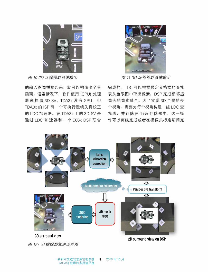
SV 和 3D SV 的示例。如图 12 所示,软件
算法将放置在车辆外围的多个视频摄像头
图 9:稀疏光流量方框图
一款针对先进驾驶员辅助系统 (ADAS) 应用的多用途平台
8 2016 年 10 月
A diverse high-performance platform for 9 October 2016 Advanced Driver Assistance System (ADAS) applications
SV systems provide rendering capabilities of the
surroundings of vehicle from any virtual viewpoint
and transitions between viewpoints. Examples of
2D SV and 3D SV are shown in Figures 10 and 11.
An SV system is constructed by stitching multiple
video cameras placed around the periphery of
the vehicle as shown in Figure 12. Typically, a
dedicated graphics processing unit (GPU) processor
would be employed for composition of 3D SV.
Since the TDA3x does not have a GPU, the 3D
SV is implemented using the combination of a
lens distortion correction (LDC) accelerator and
a C66x DSP. The GPU typically stores the entire
representation of the 3D world, allowing the user to
Fig 10. 2D Surround View System Output
Fig 11. 3D Surround View System Output
Figure 10: 2D surround view system output
Fig 10. 2D Surround View System Output
Fig 11. 3D Surround View System Output Figure 11: 3D surround view system output
Fig 12. Surround View Algorithm Flow
Figure 12: Surround view algorithm flow
的输入图像拼接起来,就可以构造出全景
画面。通常情况下,软件使用 (GPU) 处理
器来构造 3D SV。TDA3x 没有 GPU,但
TDA3x 的 ISP 有一个可执行透镜失真校正
的 LDC 加速器。在 TDA3x 上的 3D SV 是
通过 LDC 加速器和一个 C66x DSP 联合
完成的。LDC 可以根据预定义格式的查找
表从鱼眼图中取出像素,DSP 完成相邻摄
像头的像素融合。为了实现 3D 全景的多
个视角,需要为每个视角构建一组 LDC 查
找表,并存储在 flash 存储器中。这一操
作可以离线完成或者在摄像头标定期间完
图 10:2D 环视视野系统输出
图 12:环视视野算法流程图
图 11:3D 环视视野系统输出
一款针对先进驾驶员辅助系统 (ADAS) 应用的多用途平台
9 2016 年 10 月

A diverse high-performance platform for 10 October 2016 Advanced Driver Assistance System (ADAS) applications
change viewpoints. However, this can be optimized
by projecting only those 3D points that are in the
visible region. Distortion correction is required to
correct the fish-eye distortion present in the image
sensors used in SV systems. The ISP of the TDA3x
SoC has a robust LDC accelerator which performs
the distortion correction. In order to create multiple
viewpoints, a minimized 3D world map for all the
cameras and viewpoints are generated and these
viewpoints are stored in non-volatile memory. This
can be done both offline and once during the
camera setup. When the system boots up, for all
the valid viewpoints, 3D world map is read and
associated LDC mesh table is generated. Then,
these outputs from the LDC are stitched together
to obtain the 360°-view for any viewpoint. The data
flow for the same is shown in Figure 13.
3.6. Camera Monitor System (CMS)
Figure 14 shows the placement of the cameras in
a typical CMS. The algorithm processing involved
in a CMS system and its partitioning in TDA3x
SoC is shown in Figure 15 on the following page.
CMOS sensors are used to capture the scene. A
frame-rate of 60 fps is typically utilized to reduce
Hosted on an IPU
Front camera
Left camera
Right camera
Rear camera
Capture module
Sensor control (Auto white balance and exposure control)
ISP and color converted
Video frame synchronizer
Distortion correction
Camera position calibration data
3D bowl mesh tables / Virtual 3D view
Camera position calibrator
Synthesizer
Display subsystem
Bayer format 8 bit @ 30 fps
Bayer format 8 bit @ 30 fps
Bayer format 8 bit @ 30 fps
Bayer format 8 bit @ 30 fps
4 channels Bayer format 8 bit @ 30 fps
4 channels YUV format
8 bit @ 30 fps
Dewarped 4 channels, YUV format 8 bit @ 30 fps
Virtual view 2D mesh table, For each view point and camera
Hosted on a DSP
Fig 13. Surround View Data Flow Figure 13: Surround view data flow
Figure 14: CMS camera placement illustration
120ο FOV
70ο FOV 70ο FOV
Right Camera Left Camera
Fig 14. CMS Camera Placement Illustration
Rear Camera
成。当系统启动时,程序载入所有 LDC 查
找表,LDC 根据查找表采样鱼眼镜头的输
入, DSP 再把 LDC 的输出拼接在一起得
到特定视角下的全景图。动态切换查找表
就可以实现 3D 视角的平滑过渡。图 13 中
显示的是 3D SV 应用场景下的数据流。
3.6 相机反光镜系统 (CMS)图 14 显示的是常见 CMS 中的摄像头位置。
CMS 系统中涉及的处理算法和它在 TDA3x
SoC 中的分区显示在 15 图中。CMOS 传
感器被用来捕获场景。通常采用 60 fps 的
帧速率来减少汽车驾驶员可视场景的延迟。
如图 16 所示,CMOS 传感器内的数据格
式通常为 Bayer 原始数据。在被转换为可
视视频数据前,这些数据会通过 ISP 的很
多处理阶段。ISP 的主要功能为:空间噪
图 13: 环视视野数据流
图 14:CMS 摄像头位置图
一款针对先进驾驶员辅助系统 (ADAS) 应用的多用途平台
10 2016 年 10 月

A diverse high-performance platform for 11 October 2016 Advanced Driver Assistance System (ADAS) applications
latency of the scene as viewed by the car driver.
The data format of CMOS sensors is typically Bayer
raw data and it is passed through many stages
of the ISP before it is converted to viewable video
data as shown in Figure 16. Key features in the
ISP are: spatial noise filter, which helps to improve
the image quality in low-light conditions, and wide
dynamic range, which increases the dynamic range
of the scene so that bright areas are not clipped
and at the same time details in shadow (or darker)
regions are visible. This allows the CMS system
to operate in a variety of lighting conditions. ISP in
the TDA3x also outputs auto white balance (AWB)[10] and auto exposure (AE) statistics which are
used by the AEWB algorithm to dynamically adjust
the sensor exposure and scene white balance to
adapt the cameras settings, dynamically changing
lighting conditions. Additionally, focus statistics are
output by the ISP indicating the degree to which
the camera is in focus. When the camera lens is
obstructed by dirt or water, the scene will not be in
focus. Due to the safety-critical nature of the CMS
application, it is important to detect such scenarios.
Focus statistics can be used in algorithms to detect
such events, thereby warning the user of suboptimal
scene capture. The hardware LDC module is used
to adjust for lens distortion correction due to wide-
angle field of view.
A common problem associated with cameras for
visual systems like CMS is LED flickering. LEDs are
commonly used in car headlights, traffic signals
and traffic signs. LEDs are typically pulsed light
sources. However, due to persistence of vision,
our eyes cannot see the LED flicker. However,
camera sensors, especially when they operate at
low exposure time due to bright lighting conditions,
could capture LED pulses in one frame and miss the
LED pulse in the next frame causing an unpleasing
and unnatural flicker-like effect. Worst case, it could
happen that the LED pulse is not captured at all, say
a red light or car headlight, thus giving a dangerous
false scene representation to the user. A deflicker
algorithm is typically used to eliminate the flicker due
to LED lights. This is a pixel-processing-intensive
algorithm and is typically run on DSP/EVE. After the
LED deflicker algorithm, the scene is displayed on
the display through the display sub-system (DSS).
A key safety measure in a CMS system is informing
Sensor ISP
LDC
LED deflicker Blind spot object
detect
AEWB
Camera obstruction detect
Display sub system (DSS)
Overlay drawing
Frame-freeze detect
Display
1MP @ 60 fps
Exposure White balance
Data flow
Control flow
TDA3x
Write back
Focus statistics
DSP/EVE processing
HW processing
M4 processing
CRC
Fig 15. Algorithm and Data Flow in CMS
Figure 15: Algorithm and data flow in CMS
Noise filter WDR White
balance
CFA de-mosaic
RGB-to-RGB color
correction RGB to YUV
Bayer input
YUV output
Fig 16. ISP Data Flow in CMS
Figure 16: ISP data flow in CMS
声滤波器,它有助于改进低光照条件下的
图像质量,以及可以增加场景动态范围的
宽动态范围,这样的话,明亮区域不会被
过曝,而同时阴影(或较暗)区域内的细
节可被显示出来。这使得 CMS 系统可以
在多种光照条件下运行。TDA3x 内的 ISP还会输出自动白平衡 (AWB) [10] 和自动曝光
(AE) 统计数据;这些数据可被 AEWB 算法
用来动态地调节传感器曝光和场景白平衡,
以自适应外界环境的变化。此外,表示摄
像头对焦角度的对焦统计数据被 ISP输出。
当摄像头镜头被污垢或水渍遮挡时,这个
场景将不会处于对焦范围内。由于 CMS应用的安全关键属性,对这些场景进行检
测是十分重要的。对焦统计数据可在算法
中用来检测这些情况,从而提示用户这些
欠佳的场景捕捉。硬件 LDC 模块被用来调
节由广角视域造成的镜头失真校正。
与 CMS 视觉系统内摄像头相关的一个常
见问题是 LED闪烁。LED常见于汽车前灯、
交通信号和交通标志中。LED 通常为脉冲
光源。由于视觉残留,我们的眼睛无法看
到 LED 闪烁。不过,摄像头传感器,特别
是那些在明亮光照条下处于低曝光时间的
摄像头传感器,可以在一个帧中捕获 LED脉冲,而又在下一帧中错过 LED 脉冲,从
而产生让人不舒服和不自然的、类似于闪
烁的效果。根本就没有捕获 LED 脉冲时,
比如说红光或汽车前灯,会出现最差情况,
向用户提供危险的错误场景表现。一个去
闪烁算法通常被用来消除由 LED 灯造成的
闪烁。这是一个像素处理密集算法,并且
通常运行在 DSP/EVE 上。在使用了 LED去闪烁算法后,这个场景通过显示子系统
(DSS) 被显示在显示器上。CMS 系统内的
另一个关键安全方法是在帧冻结情况下通
知用户。由于用户不会一直盯着后视镜和
侧视镜,如果硬件 (HW) 或软件 (SW) 故障
时发生,显示在屏幕上的数据会被冻结,
同一帧被重复显示。这会使驾驶员和行人
都处于非常危险的环境之中。在 TDA3x中,
通过使用 DSS 来将正在被显示的像素数据
图 15:CMS 内的算法和数据流
图 16:CMS 内的 ISP 数据流
一款针对先进驾驶员辅助系统 (ADAS) 应用的多用途平台
11 2016 年 10 月

A diverse high-performance platform for 12 October 2016 Advanced Driver Assistance System (ADAS) applications
the user in case of a frame freeze scenario. Since
the user is not constantly looking at the mirror,
it could happen that due to hardware (HW) or
software (SW) failure, the data that is displayed on
the screen is frozen with the same frame repeating.
This can cause a hazardous situation to the road
users. In the TDA3x, this can be detected by using
the DSS to write back the pixel data that is being
displayed and then computing a CRC signature
for the frame using a HW CRC module. If the CRC
signature matches for a sequence of consecutive
frames, then it implies that there is frame freeze
somewhere in the system and a warning is given
to the user or the display is blanked out. Additional
analytics algorithms like object detect can be run in
the blind spot to notify the driver.
4. Results and analysis
In this section, we provide details of system
partitioning and performance of multiple applications
executing on the TDA3x SoC. TI’s TDA3x EVM
is used as the experimental platform. In order to
showcase our algorithms, we captured multiple
scenes with various camera sensors placed around
the car. The video sequence contained urban
roads with pedestrians, vehicles, traffic signs, lane
marking, traffic lights and parking lot scenarios. This
video sequence is then decoded via an HDMI player
and fed to the TDA3x EVM as shown in Figure 17.
The algorithms then utilize all of the available
HDMI receiver 1920×1080 @ 60 fps YUV 422i pre-recorded content
Resizer
1280
Multi-scale 122
HOG feature plane computation
Scale-space pyramid (YUV 420p)
Pedestrian, cyclist detection
Traffic sign recognition
Vehicle detection
640×360 (Y)
1280×720 (YUV)
Sparse optical flow
1280×720 (Y)
Structure from motion (3D cloud point)
25 fps
25 fps 25 fps
25 fps
25 fps
25 fps
25 fps
25 fps
TDA3x SOC
Lane departure warning Traffic light detection
Draw object info in video frame
Object info
HDMI display ISP C66x DSP EVE ARM® M4
Figure 17: Algorithm partitioning for front camera applications on TDA3x SoC
回写,然后使用一个 HW CRC 模块来为这
个帧计算一个 CRC 特征,从而检测出这个
情况。如果这个 CRC 特征与一系列的连续
帧匹配,那么这意味着系统中的某个位置
出现了帧冻结,需要向用户报警,或者显
示屏空白。以通知驾驶员。
4. 效果与分析
在这一部分,我们会给出系统分区的细
节,以及 TDA3x SoC 上执行的多个应用
的性能。TI 的 TDA3x EVM 被用作实验平
台。为了演示我们的算法,我们用放置在
汽车周围的不同摄像头传感器来捕获多个
场景。这个视频序列包含充满了行人、车
辆、交通信号、车道标志、交通信号灯和
停车位的城市道路。如图 17 所示,通过一
个 HDMI 播放器对这个视频序列解码,并
且馈入 TDA3x EVM 中。然后,这个算法
利用 ISP、EVE、DSP 和 ARM Cortex-M4等所有可用的计算块来执行 OD、LDW、
TSR、SFM、SV 和 CMS 等不同函数。这
些算法的输出被提供给 ARM Cortex-M4来从原始图像中提取这些标记,并且将已
经注释的视频发出,进行 HDMI 显示。一
个 LCD 显示屏被用来观看视频,连同物体
标记,以确认算法的运行方式是否与预期
图 17:针对 TDA3x SoC 的前端摄像头应用的算法分区
一款针对先进驾驶员辅助系统 (ADAS) 应用的多用途平台
12 2016 年 10 月

A diverse high-performance platform for 13 October 2016 Advanced Driver Assistance System (ADAS) applications
compute blocks such as ISP, EVE, DSP and ARM
Cortex-M4 to perform various functions such as OD,
LDW, TSR, SFM, SV and CMS. The output of these
algorithms is provided to the ARM Cortex-M4 to
draw these markings in the original video and send
out the annotated video to the HDMI display. An
LCD display is used to watch the video along with
object markings to confirm the expected behavior of
algorithms. The configuration parameters of these
algorithms are listed in Table 1.
In the case of front camera applications, the capture
is configured for 25 frames per second (fps). As
a first step, multiple scales of the input frame are
created by using resizer functionality in the ISP. The
scale space pyramid is useful to detect objects
of different sizes with a fixed-size template. For
every relevant pixel in these scales, histogram of
oriented gradients (HOG)[9] signatures are formed.
This module involves intensive calculations at
the pixel level and hence executed on the EVE.
After formation of the HOG feature plane, the EVE
runs the SOF algorithm and the C66x DSP1 runs
the adaboost classifier stage of object detection
algorithm. The classifier is executed separately for
each object category such as pedestrians, vehicles,
cyclists and traffic signs. From the scale space
pyramid, 640 × 360 and 1280 × 720 scale is fed
to DSP2 on which lane detection and traffic light
recognition algorithms are run. After completion
of SOF, the EVE sends the optical flow tracks to
DSP2 to perform triangulation to obtain 3D location
of key points in the frame, thereby helping to
identify distance of various objects in the scene.
In this setup, the ARM Cortex-M4 manages the
capture and display device, feeds the data to the
ISP and collects information from the DSPs before
annotating the objects and displaying them.
For SV application, four channels of video of
resolution 1280 × 800 at 30 fps are captured
from RAW video sensors in Bayer format, which
is supported by the ISP. The ISP then converts
the Bayer format data to YUV format for further
processing. Auto white balance and exposure-
control algorithms ensure each video source is
photometrically aligned. Then, the camera calibrator
will generate the required mesh table for distortion
correction based on the view point and distortion
correction is performed. Synthesizer will then receive
the corrected images and stitch to form the SV
output with a resolution of 752 × 1008 at 30 fps.
In the case of CMS, each camera input operates on
one TDA3x SoC. Each channel of video of resolution
1280 × 800 at 60 fps are captured from RAW video
sensors (Bayer format) which is supported by the
ISP. The ISP then converts the Bayer format data
to YUV format, as shown in Figure 16. Algorithms
such as OD are run for blind spot detection. Also, a
deflicker algorithm is run to remove any LED flicker-
related issues, before displaying it to the driver.
AlgorithmFrame rate Configuration details on TDA3x SoC
Vehicle, pedestrian, cycle detect
25 Resolution = 1280 × 720, multi-scaleMinimum object size = 32 × 64
Traffic sign recognition
25 Resolution = 1280 × 720, multi-scaleMinimum object size = 32 × 32
Traffic light recognition
25 Resolution = 1280 × 720Radii range = 8
Lane depart warning
25 Resolution = 640 × 360Number of lanes detected = 2
Structure from motion
25 Resolution = 1280 × 720Number of SOF tracks = 1K points3D cloud points generated = 800
Surround view system
30 Input resolution = 4 channels of 1280 × 800Output resolution = 752 × 1008
Camera mirror system
60 Number of video channels = 1Input resolution = 1280 × 800
Table 1: Algorithm configurations
的一样。这些算法的配置参数在表 1 中列
出。
在前置摄像头应用中,捕捉被配置为每
秒 25 帧 (fps)。第一步,通过使用 ISP 内
的缩放器改变输入帧的尺寸。尺度空间金
字塔在用固定尺寸模板检测不同大小物体
方面十分有用。对于这些尺寸内的每一个
相关像素,方向梯度直方图 (HOG)[9] 特征
被形成。这个模块涉及像素等级上的大量
计算,并因此在 EVE 上执行。在 HOG 特
征平面形成后,EVE 运行 SOF 算法,而
C66x DSP1 运行物体检测算法的 adaboost分类器阶段。对于每一个物体类别,比如
行人、车辆、自行车手和交通信号,这个
分类器单独执行。从尺度空间金字塔,
640X360 和 1280x720 被馈入 DSP2,而
车道检测和交通信号灯识别算法在其上运
行。在 SOF 完成后,EVE 发送光流轨迹至
DSP2,以执行三角剖分,从而获得这个
帧内关键点的 3D 位置,因此有助于识别
场景中不同物体的距离。在这个设置中,
ARM Cortex-M4 管理捕获和显示器件、将
输入馈入 ISP,并且在对物体进行注释并
显示它们前从 DSP 中搜集信息。
对 于 SV 应 用 来 说,4 条 分 辨 率 为
1280x800,帧速率为 30fps 的通道,被
以 ISP 所支持的 Bayer 的格式从 RAW 视
频传感器中被捕捉。然后,ISP 将 Bayer格式的数据转换为 YUV 格式,以进行进
一步处理。自动白平衡和曝光控制算法确
保了每个视频源都是亮度和色度校准的。
然后,LDC 将根据对应视角的 LDC 查找
表执行失真校正。然后,合成器将接收校
正后的图像并进行拼接,以形成分辨率为
752x1008,帧速率为 30fps 的 SV 输出。
在使用 CMS 的情况下,每个摄像头输入
运行在一个 TDA3x SoC 上。每个通道上
1280x800 分辨率,帧速率为 60fps 的视频
被从 ISP 所支持的 RAW 视频传感器中捕
获(格式为Bayer)。然后,如图 16中所示,
这个 ISP 将 Bayer 格式数据转换为 YUV 格
式。诸如OD等算法被用来进行盲点检测。
此外,在将其显示给驾驶员之前,还运行
一个去闪烁算法来消除与 LED 闪烁有关的
所有问题。
算法 帧速率 TDA3x SoC 上的配置细节
车 辆、 行人、 自 行车检测
25分辨率 =1280x720,多尺度
最小物体尺寸 = 32x64
交通信号识别
25分辨率 =1280x720,多尺度
最小物体尺寸 = 32x64
交通信号灯识别
25分辨率 =1280x720
半径范围 =8
车道偏离报警
25分辨率 =640x360
检测的车道数量 =2
运动恢复结构
25
分辨率 =1280x720
SOF 数量 =1K 点
生成的 3D 云点 =800
环视视野系统
30输入分辨率 =4 条通道,1280x800
输出分辨率 =752x1008
摄像头镜像系统
60视频通道数量 =1
输入分辨率 =1280x800
表 1:算法配置
一款针对先进驾驶员辅助系统 (ADAS) 应用的多用途平台
13 2016 年 10 月

A diverse high-performance platform for 14 October 2016 Advanced Driver Assistance System (ADAS) applications
Table 2 shows the loading of the various processors
of the TDA3x SoC while running these algorithms.
For front-camera applications, 53 percent of DSP1,
66 percent of DSP2, 79 percent of EVE and 33
percent of one ARM Cortex-M4 are utilized.
For SV application, 45 percent of DSP1 is utilized
and 44 percent of one ARM Cortex-M4 is utilized.
The unused C66x DSP and EVE can be used to
run analytics on the SV output if needed. For CMS
application, 68 percent of DSP1 is consumed to
run the deflicker algorithm and 20 percent of DSP2
and 40 percent of EVE is used for the blind spot
detection algorithm.
5. Conclusion
ADAS applications require high-performance,
low-power and low-area solutions. In this paper,
we have presented one such solution based on
Texas Instruments’ TDA3x device. The paper
provided insight into key algorithms of ADAS such
as front camera, surround view and camera monitor
systems and presented the system partitioning
of these algorithms across multiple cores present
in the TDA3x SoC and their performance has
been provided. Additionally, it has shown that
TI’s TDA3x platform is able to generate 3D SV
efficiently, without a GPU. We have also shown that
the TDA3x platform is able to map various ADAS
algorithms and still have headroom for customer’s
differentiation. For more information on the TDA3x
platform visit www.ti.com/TDA.
References[1] Cortex-M4: Technical reference manual, ARM
Inc., 2010.
[2] Global Health Observatory (GHO) data, 2013.
[3] TMS320C66x DSP: User guide, SPRUGW0C,
Texas Instruments Inc., 2013.
[4] TDA3x SoC processors for advanced driver assist
systems (ADAS) technical brief, Texas Instruments
Inc., 2014.
[5] The top 10 causes of death, 2014.
[6] 2020 Roadmap, Rev. 1, European New Car
Assessment Programme, 2015.
[7] Advanced driver assistance system (ADAS) guide
2015, Texas Instruments Inc., 2015. Supplied as
material SLYY044A.
[8] S. Dabral, S. Kamath, V. Appia, M. Mody, B.
Zhang, and U. Batur. Trends in camera-based
automotive driver assistance systems (ADAS).
IEEE 57th International Midwest Symposium on
Circuits and Systems (MWSCAS), pages 1110–
1115, 2014.
[9] N. Dalal and B. Triggs. Histograms of oriented
gradients for human detection. IEEE Computer
Society Conference on Computer Vision and
Pattern Recognition (CVPR), 1:886–893, 2005.
[10] H. Garud, U. K. Pudipeddi, K. Desappan, and
S. Nagori. A fast color constancy scheme for
automobile video cameras. International
Algorithms DSP1 utilization DSP2 utilization EVE utilizationARM Cortex-M4
utilization Frame rate (fps)
Front camera analytics 53% 66% 79% 33% 25
Surround view system 45% 0% 0% 44% 30
Camera mirror system 68% 20% 40% 30% 60
Table 2: Performance estimates for different applications on the TDA3x SoC
表 2 显示的是在运行这些算法时,TDA3x
SoC 的不同处理器的负载。对于前置摄像
头应用来说,DSP1、DSP2、EVE 和一个
ARM Cortex-M4 的利用率分别为 53%、
66%、79% 和 33%。
对于 SV 应用来说,DSP1 的利用率为
45%,而一个 ARM Cortex-M4 的利用率
为 44%。未使用的 C66x DSP 和 EVE 可
被用来在需要时对 SV 输出进行分析。
对于 CMS 应用来说,DSP1 运算能力的
68% 被用来运行去闪烁算法,而 DSP2 的
20% 和 EVE 的 40% 用于盲点检测算法。
5. 结论
ADAS 应用要求高性能、低功耗和低占用
空间解决方案。在这篇文章中,我们已经
给出了一个基于德州仪器 (TI) TDA3x 器
件的解决方案。这篇文章深入研究了前置
摄像头、环视视野和摄像头监视系统的主
要 ADAS 算法,并且给出了这些算法在
TDA3x SoC 的多个内核上的系统分区,
并且提供了它们所具有的性能。此外,
我们已经知道在没有 GPU 的情况下,TI的 TDA3x 平台能够高效地生成 3D SV。
我们还证明了 TDA3x 平台能够执行不同
的 ADAS 算法,并且针对用户的差别化
要求仍然有性能提升的空间。如需获得与
TDA3x 平台相关的更多信息,敬请访问
www.ti.com/TDA。
参考书目
[1] Cortex-M4:技术参考手册,ARM 公司,
2010 年
[2] 全球健康观察站 (GHO) 数据,2013 年
[3] TMS320C66x DSP: 用 户 指 南,
SPRUGW0C,德州仪器 (TI) 公司,2013年
[4] 针对先进驾驶员辅助系统 (ADAS) 的
TDA3x SoC处理器技术简报,德州仪器 (TI) 公司,2014 年
[5] 致死 10 大原因,2014 年
[6] 2020 路线图,修订版本 1,欧洲新车
安全评鉴协会,2015
[7] 2015 年先进驾驶员辅助系统 (ADAS) 指
南,德州仪器 (TI) 公司,2015 年,材料名
SLYY044A
[8] S. Dabral,S.Kamath,V.Appia,M.Mody,
B.Zhang 和 U.Batur。基于摄像头的先进驾
驶员辅助系统 (ADAS) 的发展趋势。IEEE第 57 届国际中西部电路与系统研讨会
算法 DSP1 利用率 DSP2 利用率 EVE 利用率
ARM Cortex-M4利用率 帧速率 (fps)
前置摄像头分析 53% 66% 79% 33% 25环视视野系统 45% 0% 0% 44% 30摄像头镜像系统 68% 20% 40% 30% 60表 2:针对 TDA3x SoC 上不同应用的性能估计值
一款针对先进驾驶员辅助系统 (ADAS) 应用的多用途平台
14 2016 年 10 月

Conference on Signal Processing and Commu-
nications (SPCOM), pages 1–6, 2014.
[11] R. Hartley and A. Zisserman. Multiple View
Geometry in Computer Vision. Cambridge
University Press, ISBN: 0521540518, second
edition, 2004.
[12] B. Kisaanin and M. Gelautz. Advances in
Embedded Computer Vision. Advances in
Computer Vision and Pattern Recognition.
Springer, 2014.
[13] Z. Lin, J. Sankaran, and T. Flanagan. Empower-
ing automotive with TI’s vision accelerationpac,
2013. http://www.ti.com/lit/wp/spry251/
spry251.pdf.
[14] B. Lucas and T. Kanade. An iterative image
registration technique with an application to
stereo vision. International Joint Conference on
Artificial Intelligence, 81:674–679, 1981.
[15] M. Mody, N. Nandan, H. Sanghvi, R. Allu, and
R. Sagar. Flexible wide dynamic range (WDR)
processing support in image signal processor
(ISP). IEEE International Conference on
Consumer Electronics (ICCE), pages 467–479,
2015.
[16] M. Mody, P. Swami, K. Chitnis, S. Jagannathan,
K. De-sappan, A. Jain, D. Poddar, Z. Nikolic,
P. Viswanath, M. Mathew, S. Nagori, and H.
Garud. High-performance front camera ADAS
applications on TI’s TDA3x platform. IEEE 22nd
International Conference on High-Performance
Computing (HiPC), pages 456–463, 2015.
[17] P. Sturm and B. Triggs. A factorization-based
algorithm for multi-image projective structure
and motion. European Conference on Computer
Vision (ECCV), 2:709–720, 1996.
[18] P. Viola and M. Jones. Fast and robust
classification using asymmetric adaboost
and a detector cascade. Advances in Neural
Information Processing System, 2001.
[19] P. Viswanath and P. Swami. A robust and
real-time image-based lane departure warning
system. In Proceedings. IEEE Conference on
Consumer Electronics (ICCE), 2016.
[20] P. Viswanath, P. Swami, K. Desappan, A.
Jain and A. Pathayapurakkal. Orb in 5 ms: An
efficient SIMD friendly implementation. Computer
Vision-ACCV 2014 Workshops, pages 675–686,
2014.
[21] B. Zhang, V. Appia, I. Pekkucuksen, A. U. Batur,
P. Shastry, Liu, S. Sivasankaran, K. Chitnis,
and Y. Liu. A surround video camera solution
for embedded systems. IEEE Conference on
Computer Vision and Pattern Recognition Work-
shops (CVPRW), pages 676–681, 2014.
SPRY302© 2016 Texas Instruments Incorporated
Important Notice: The products and services of Texas Instruments Incorporated and its subsidiaries described herein are sold subject to TI’s standard terms and conditions of sale. Customers are advised to obtain the most current and complete information about TI products and services before placing orders. TI assumes no liability for applications assistance, customer’s applications or product designs, software performance, or infringement of patents. The publication of information regarding any other company’s products or services does not constitute TI’s approval, warranty or endorsement thereof.
The platform bar is a trademark of Texas Instruments. All other trademarks are the property of their respective owners.
(MWSCAS),1110-1115 页,2014 年
[9] N.Dalal 和 B.Triggs。针对人类检测的方
向梯度直方图。IEEE 关于计算机视觉和图
形识别的计算机学会会议 (CVPR),1:886-
893,2005 年
[10] H.Garud,U.K.Pudipeddi,K.Desappan和 S.Nagori。针对汽车视频摄像头的快速
色彩恒常机制。国际信号处理和通信会议
(SPCOM),1-6 页,2014 年
[11] R.Harley 和 A.Zisserman。计算机视
觉内的多视图几何图形。剑桥大学出版社,
ISBN:0521540518,第二版,2014 年
[12] B.Kisaanin 和 M.Gelautz。嵌入式计算
机视觉的进步。计算机视觉与图形识别的
进步。Spriner,2014 年
[13] Z.Lin,J.Sankaran 和 T.Flanagan。 用
TI 的视觉加速包来使汽车更加强大,2013年。http://www.ti.com/lit/wp/spry251/
spry251.pdf
[14] B.Lucas 和 T.Kanade。用一个应用通
过迭代图像配准技术实现的 3D 视觉。国
际人工智能联合会议,81:674-679,1981 年
[15] M.Mody,N.Nandan,H.SangHvi,
R.Allu 和 R.Sagar。图像信号处理器 (ISP) 内支持的灵活宽动态范围 (WDR) 处理。
IEEE 消费类电子产品国际会议 (ICCE),
467-479 页,2015 年
[16] M.Mody,P.Swami,K.Chitnis,
S.Jagannathan,K.De-sappan,A.Jain,
D.Poddar,Z.Nikolic,P.Viswanath,
M.Mattew,S.Nagori 和 H.Garud。TI 的
TDA3x 平台上的高性能前置摄像头 ADAS应用。IEEE 第 22 届高性能计算国际会议
(HiPC),456-463 页,2015 年
[17] P.Sturm 和 B.Triggs。针对多图像投
射结构和运动的基于因数分解的算法。欧
洲计算机视觉会议 (ECCV),2:709-720,
1996 年
[18] P.Viola 和 M.Jones。 使 用 非 对 称
adaboost 和一个探测器级联实现的快速
和稳健分类。神经信息处理系统的进展,
2001 年
[19] P.Viswanath 和 P.Swami。一个稳健耐
用和基于实时图像的车道偏离报警系统。
IEEE 消费类电子产品会议 (ICCE),2016年
[20] P.Viswanath,P.Swami,K.Desappan,
A.Jain 和 A.Pathayapurakai。5ms 内完成
并联连接指令 (Orb):一个高效地 SIMD 友
好型实现方式。计算机视觉 -ACCV 2104研讨会,675-686 页,2014 年
[21] B.Zhang,V.Appia,I.Pekkucuksen,
A.U.Batur,P.Shastry,Liu,S.Sivasankaran,
K.Chitnis 和 Y.Liu。一款针对嵌入式系统
的环视视频摄像头解决方案。IEEE 计算机
视觉和图形识别研讨会议 (CVPRW),676-
681 页,2014 年
ZHCY073

重重要要声声明明
德州仪器(TI) 及其下属子公司有权根据 JESD46 最新标准, 对所提供的产品和服务进行更正、修改、增强、改进或其它更改, 并有权根据JESD48 最新标准中止提供任何产品和服务。客户在下订单前应获取最新的相关信息, 并验证这些信息是否完整且是最新的。所有产品的销售都遵循在订单确认时所提供的TI 销售条款与条件。
TI 保证其所销售的组件的性能符合产品销售时 TI 半导体产品销售条件与条款的适用规范。仅在 TI 保证的范围内,且 TI 认为 有必要时才会使用测试或其它质量控制技术。除非适用法律做出了硬性规定,否则没有必要对每种组件的所有参数进行测试。
TI 对应用帮助或客户产品设计不承担任何义务。客户应对其使用 TI 组件的产品和应用自行负责。为尽量减小与客户产品和应 用相关的风险,客户应提供充分的设计与操作安全措施。
TI 不对任何 TI 专利权、版权、屏蔽作品权或其它与使用了 TI 组件或服务的组合设备、机器或流程相关的 TI 知识产权中授予 的直接或隐含权限作出任何保证或解释。TI 所发布的与第三方产品或服务有关的信息,不能构成从 TI 获得使用这些产品或服 务的许可、授权、或认可。使用此类信息可能需要获得第三方的专利权或其它知识产权方面的许可,或是 TI 的专利权或其它 知识产权方面的许可。
对于 TI 的产品手册或数据表中 TI 信息的重要部分,仅在没有对内容进行任何篡改且带有相关授权、条件、限制和声明的情况 下才允许进行复制。TI 对此类篡改过的文件不承担任何责任或义务。复制第三方的信息可能需要服从额外的限制条件。
在转售 TI 组件或服务时,如果对该组件或服务参数的陈述与 TI 标明的参数相比存在差异或虚假成分,则会失去相关 TI 组件 或服务的所有明示或暗示授权,且这是不正当的、欺诈性商业行为。TI 对任何此类虚假陈述均不承担任何责任或义务。
客户认可并同意,尽管任何应用相关信息或支持仍可能由 TI 提供,但他们将独力负责满足与其产品及在其应用中使用 TI 产品 相关的所有法律、法规和安全相关要求。客户声明并同意,他们具备制定与实施安全措施所需的全部专业技术和知识,可预见 故障的危险后果、监测故障及其后果、降低有可能造成人身伤害的故障的发生机率并采取适当的补救措施。客户将全额赔偿因 在此类安全关键应用中使用任何 TI 组件而对 TI 及其代理造成的任何损失。
在某些场合中,为了推进安全相关应用有可能对 TI 组件进行特别的促销。TI 的目标是利用此类组件帮助客户设计和创立其特 有的可满足适用的功能安全性标准和要求的终端产品解决方案。尽管如此,此类组件仍然服从这些条款。
TI 组件未获得用于 FDA Class III(或类似的生命攸关医疗设备)的授权许可,除非各方授权官员已经达成了专门管控此类使 用的特别协议。
只有那些 TI 特别注明属于军用等级或“增强型塑料”的 TI 组件才是设计或专门用于军事/航空应用或环境的。购买者认可并同 意,对并非指定面向军事或航空航天用途的 TI 组件进行军事或航空航天方面的应用,其风险由客户单独承担,并且由客户独 力负责满足与此类使用相关的所有法律和法规要求。
TI 已明确指定符合 ISO/TS16949 要求的产品,这些产品主要用于汽车。在任何情况下,因使用非指定产品而无法达到 ISO/TS16949 要求,TI不承担任何责任。
产产品品 应应用用
数字音频 www.ti.com.cn/audio 通信与电信 www.ti.com.cn/telecom放大器和线性器件 www.ti.com.cn/amplifiers 计算机及周边 www.ti.com.cn/computer数据转换器 www.ti.com.cn/dataconverters 消费电子 www.ti.com/consumer-appsDLP® 产品 www.dlp.com 能源 www.ti.com/energyDSP - 数字信号处理器 www.ti.com.cn/dsp 工业应用 www.ti.com.cn/industrial时钟和计时器 www.ti.com.cn/clockandtimers 医疗电子 www.ti.com.cn/medical接口 www.ti.com.cn/interface 安防应用 www.ti.com.cn/security逻辑 www.ti.com.cn/logic 汽车电子 www.ti.com.cn/automotive电源管理 www.ti.com.cn/power 视频和影像 www.ti.com.cn/video微控制器 (MCU) www.ti.com.cn/microcontrollersRFID 系统 www.ti.com.cn/rfidsysOMAP应用处理器 www.ti.com/omap无线连通性 www.ti.com.cn/wirelessconnectivity 德州仪器在线技术支持社区 www.deyisupport.com
IMPORTANT NOTICE
Mailing Address: Texas Instruments, Post Office Box 655303, Dallas, Texas 75265Copyright © 2016, Texas Instruments Incorporated

![[XLS] · Web view您的驾驶证(FH00*801)换证期限为2014-12-01,请按时办理换证业务。 272 梁秋平 您的驾驶证(442000*3821)换证期限为2014-12-01,请按时办理换证业务。273](https://img.dokumen.tips/doc/110x75/5b4222137f8b9afb298b6ce3/xls-web-viewfh008012014-12-01.jpg)

![[XLS] · Web view您的驾驶证(FH00*700)换证期限为2016-04-19,目前因逾期1年已被注销,您可在2019-04-19前办理恢复驾驶资格业务。 770 412902197510292077](https://img.dokumen.tips/doc/110x75/5b4222137f8b9afb298b6ce7/xls-web-viewfh007002016-04-1912019-04-19.jpg)


![[XLS]sd.122.gov.cn · Web view潍坊市交警支队车辆管理所_驾驶人_20170818 1 您的驾驶证(370721*1230)上一记分周期为2016-08-18至2017-08-18,期间没有记分,免予本记分周期审验。刘加超](https://img.dokumen.tips/doc/110x75/5b4222137f8b9afb298b6ce0/xlssd122govcn-web-view20170818.jpg)