Embed Size (px)
Citation preview

Owner'sManual
- March, 1997 -
¥ Freestanding Direct-Vent Stove
¥ Natural Gas or Propane
¥ Residential or Mobile Home
ANSI Z21.44, Z21.11.4CAN/CGA 1-2.19-M81, IR41, IR55, 2.17-M91
WARNING: If the information in this manual is not followed exactly, a fire or explosion mayresult causing property damage, personal injury or loss of life.
- Do not store or use gasoline or other flammable vapors and liquids in the vicinity of this or anyother appliance.
- WHAT TO DO IF YOU SMELL GAS¥ Do not try to light any appliance.¥ Do not touch any electrical switch; do not use any phone in your building.¥ Immediately call gas supplier from a neighbor's phone. Follow the gas supplier's instructions.¥ If you cannot reach your gas supplier, call the fire department.
- I ns tal lat ion and s er vi ce m ust be per f or m ed by a qua lif i ed ins ta lle r , se r vice agency or t he gas s upplie r .
Heritage Bay DV Gas Stove
10850 117th Place N.E. Kirkland, WA 98033OMNI
Listed
PAGE 2 SAFETY PRECAUTIONS
¥ IF YOU SMELL GAS:
* Do not light any appliance* Extinguish any open flame* Do not touch any electrical switch or plug or unplug anything* Open windows and vacate building* Call gas supplier from neighbor's house, if not reached, call firedepartment¥ This unit must be installed by a qualified installer to prevent the possibility of
an explosion. Your dealer will know the requirements in your area and caninform you of those people considered qualified. The room heater should beinspected before use and at least annually by a qualified service person. Morefrequent cleaning may be required due to excessive lint from carpeting,bedding material, etc.
¥ The instructions in this manual must be strictly adhered to. Do not usemakeshift methods or compromise in the installation. Improper installationwill void the warranty and safety listing.
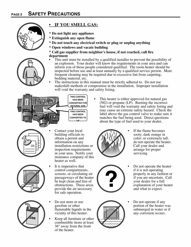
THIS CONTROL HAS BEEN
CONVERTED TO LP
THIS CONTROL HAS BEEN
CONVERTED FOR NATURAL GAS
¥ This heater is either approved for natural gas(NG) or propane (LP). Burning the incorrectfuel will void the warranty and safety listing andmay cause an extreme safety hazard. Check thelabel above the gas control valve to make sure itmatches the fuel being used. Direct questionsabout the type of fuel used to your dealer.
Ok
¥ Contact your localbuilding officials toobtain a permit andinformation on anyinstallation restrictions orinspection requirementsin your area. Notify yourinsurance company of thisheater as well.
¥ If the flame becomessooty, dark orange incolor, or extremely tall,do not operate the heater.Call your dealer andarrange for properservicing.
¥ It is imperative thatcontrol compartments,screens, or circulating airpassageways of the heaterbe kept clean and free ofobstructions. These areasprovide the air necessaryfor safe operation.
?¥ Do not operate the heater
if it is not operatingproperly in any fashion orif you are uncertain. Callyour dealer for a fullexplanation of your heaterand what to expect.
Gas
¥ Do not store or usegasoline or otherflammable liquids in thevicinity of this heater.
¥ Keep all furniture or othercombustible items at least36" away from the frontof the heater. AAAAA
AAAAAAAAAAAAAAAAAAA
¥ Do not operate if anyportion of the heater wassubmerged in water or ifany corrosion occurs.

SAFETY PRECAUTIONS (CONTINUED) PAGE 3
¥ Do not place clothing orother flammable items onor near the heater.Because this heater can becontrolled by a thermostatthere is a possibility of theheater turning on andigniting any items placedon or near it.
AAAAAAAAA
¥ Light the heater using thebuilt-in piezo igniter. Donot use matches or anyother external device tolight your heater.
¥ Never remove, replace,modify or substitute anypart of the heater unless
¥ The viewing glass shouldbe opened for serviceonly (see the maintenancesection of this manual).
¥ Any safety screen orguard removed forservicing must bereplaced prior tooperating the heater.
instructions are given inthis manual. All otherwork must be done by atrained technician. Don'tmodify or replaceorifices.
¥ Allow the heater to coolbefore carrying out anymaintenance or cleaning.
¥ Operate the heateraccording to theinstructions included inthis manual.
¥ If the main burners do notstart correctly turn the gasoff at the gas controlvalve and call your dealerfor service.
¥ The pilot flame mustcontact the thermopileand thermocouple (see theillustration to the left). Ifit does not, turn the gascontrol valve to "OFF"and call your dealer.
AAAAAAAA
¥ This unit is not for usewith solid fuel
¥ Do not place anythinginside the firebox (exceptthe included fiber logs).
¥ If the fiber logs becomedamaged, replace withTravis Industries log set.
ThisManual
¥ Do not throw this manualaway. This manual hasimportant operating andmaintenance instructionsthat you will need at alater time. Always followthe instructions in thismanual.
¥ Do not touch the hotsurfaces of the heater.Educate all children of thedanger of a high-temperature heater.Young children should besupervised when they arein the same room as theheater.
¥ Plug the heater into a120V grounded electricaloutlet. Do not remove thegrounding plug.
¥ Don't route the electricalcord in front of, over, orunder the heater
¥ Instruct everyone in thehouse how to shut gas offto the appliance and at thegas main shutoff valve.The gas main shutoffvalve is usually next tothe gas meter or propanetank and requires awrench to shut off.
¥ Travis Industries, Inc.grants no warranty,implied or stated, for theinstallation ormaintenance of yourheater, and assumes noresponsibility of anyconsequentialdamage(s).

PAGE 4 TABLE OF CONTENTS
Introduction & Important Info. ................ 1
Safety Precautions ..................................... 2
Features & Specifications ........................ 5
Installation Options ................................... 5
Heating Specifications ............................... 5
Dimensions ............................................. 5
Fuel, Emissions, Electrical.......................... 5
Stove InstallationInstallation Preparation .............................. 6
Items Required for Installation..................... 6
Items Packed with the Heritage Bay ............. 6
Order of Installation .................................. 6
Stove Clearances ..................................... 6
Stove Placement Requirements .................. 7
Floor Protection Requirements .................... 7
Gas Line Installation ................................. 7
Vent Requirements ................................... 8
Approved Vent Configurations..................... 9
Restrictor Position .............................. 9
Elbows ............................................. 9
Measuring Vent Lengths ...................... 9
Approved Vent Config's with No Elbowsor Two 45° Offsets (Vertical Term.) ........ 10
Approved Vent Config's with aHorizontal Termination......................... 11
Approved Vent Config's with a VerticalTermination and Two 90° Elbows........... 12
Horizontal Vent Termination Requirements .... 13
Vertical Vent Termination Requirements ....... 13
Electrical Connection ................................ 13
Finalizing the InstallationDoor Opening .......................................... 14
Log, Twig, and Ember Installation ................ 15
Leak Test the Gas Line.............................. 16
Pilot Flame Inspection ............................... 16
Air Shutter Adjustment............................... 16
Flame Inspection...................................... 16
Explain Heater Operation to Owner .............. 16
Operating Your HeaterBefore You Begin ..................................... 17
Location of Controls .................................. 17
Starting The Pilot Flame ............................ 18
Starting the Heater for the First Time ............ 19
Turning the Heater On and Off .................... 19
Adjusting the Flame Height......................... 19
Adjusting the Blower Speed........................ 20
Normal Operating Sounds .......................... 20
Maintaining Your HeaterCleaning Your Heater................................ 21
Yearly Service Procedure........................... 21
Adjusting the Door .................................... 22
TroubleshootingTroubleshooting Table............................... 23
How this Heater Works .............................. 24
Wiring Diagram........................................ 25
Warranty .......................................................26
Listing Information ....................................27
Optional EquipmentLP Conversion ......................................... 28
Thermostat Installation .............................. 32
Remote Control Thermostat........................ 33
AddendumAltitude Considerations.............................. 35
Class A Chimney Conversion Kit ................. 35
Index 36
Symbols Used in this ManualThe illustration below details what the symbols used along the left margin indicate.
Requirement
¥ 1 ! ? +
HintNoteWarningStep

FEATURES AND SPECIFICATIONS PAGE 5
Installation Options:
¥ Freestanding
¥ Residential or Mobile Home
¥ Horizontal or Vertical Vent
¥ Class A Chimney Retrofit
Features:¥ Works During Power Outages (millivolt system)¥ High Efficiency; Up to 79% for Natural Gas,
80% for LP (Steady State)¥ Optional Thermostat or Remote Control¥ Realistic "Wood Fire" Look¥ Convenient Operating Controls¥ Variable-Rate Heat Output¥ Quiet Blower for Effective Heat Distribution¥ Low Maintenance
Heating Specifications: Natural Gas LP (Propane)
Approximate Heating Capacity (in square feet)* 1,200 - 2,000 1,200 - 2,000High Burn Input Rate (In BTU's) 40,000 40,000Low Burn Input Rate (In BTU's) 23,700 23,000Efficiency** 79% 80%AFUE (Annual Fuel Utilization Efficiency) 71% 72%* Heating capacity will vary with the home's floor plan and insulation, natural gas or Propane BTU rating, and outside temperature.
** Efficiency rating is a product of thermal efficiency rating determined under continuous operation independent of installed system.To measure the net BTU's, multiply the BTU input by the efficiency percentage (79% for natural gas, 80% for LP).
mensions:
uel:The heater is designedeither for natural gas or forpropane. Check the stickeron the top of the gascontrol valve.
missions:This unit has passed theANSI emission standardsfor vented room heaters astested by OMNIEnvironmental Services,Inc.
ectrical Specifications:
120 Volts, 1.3 Amps, 60Hz (150 watts on high)
27-3/8" (695 mm)
8-1/4" (210 MM)
Weight: 275 Lbs
(125 kg).
32-3/8Ó(822 mm)
20-3/8"(518 mm)
Measure Clearances from the Stove Top
The starter section is 3/4" (19 mm) below the top.
PAGE 6 STOVE INSTALLATION - For Qualified Installers Only!
Installation Preparation! Failure to follow all of the requirements may result in property damage, bodily injury, or even
death.! This appliance must be installed in accordance with all local codes, if any; if not, follow ANSI
Z223.1 and NFPA 54(88).! In Manufactured or Mobile Homes must confirm with: In USA, Manufactured Home Construction
and Safety Standard, Title 24 CFR, Part 3280; In Canada, CSA Z240.4 and Gas-EquippedRecreational Vehicles and Mobile Housing. This appliance may be installed in ManufacturedHousing only after the home is site located.
! This appliance is designed for natural gas or propane (LP). Check the sticker on top of the gascontrol valve.
! All exhaust gases must be vented outside the structure of the living-area. Combustion air is drawnfrom outside the living-area structure.
! Notify your insurance company before hooking up this appliance.! The requirements below are divided into sections - all requirements must be met simultaneously.
ems Required for Installation¥ Simpson Duravent (see page 8 for part #'s) & Silicone ¥ Gas Hookup Equipment
ems Packed with the Heritage Bay¥ Heritage Bay¥ Propane Conversion Kit
¥ Log Set (2 Logs, 2 Twigs, Embers)
rder of Installation1 If using propane, follow the converstion instructions on
page 282 Position the heater, use floor protection if needed
3 Connect the gas line. Connect the gas vent.4 Follow the instructions under "Finalizing the
Installation" on pages 14 through 16
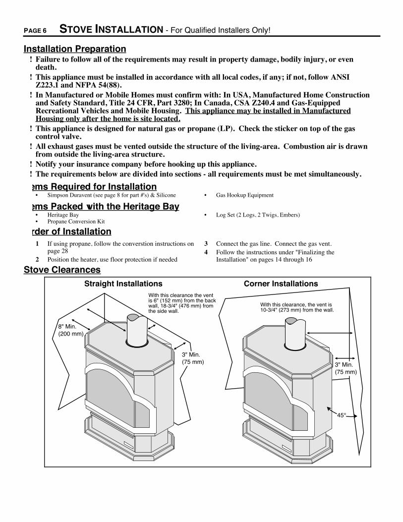
Stove Clearances
8" Min.(200 mm)
3" Min. (75 mm)
With this clearance the vent is 6" (152 mm) from the back wall, 18-3/4" (476 mm) from the side wall.
Straight Installations Corner Installations
With this clearance, the vent is 10-3/4" (273 mm) from the wall.
45¡
3" Min. (75 mm)

STOVE INSTALLATION (CONT.) - For Qualified Installers Only! PAGE 7
Heater Placement Requirements¥ Heater must be installed on a level surface capable of supporting the heater and vent¥ Due to the high temperature of the heater, it should be located out of traffic and away from furniture
and draperies. Heater must be placed so no combustibles are within, or can swing within 36" (910mm) of the front of the heater (e.g. drapes, doors)
? When placed in a location where the floor to ceiling height is under 7 feet (2130 mm), theinstallation is considered an alcove and must meet the following requirements:¥ The alcove floor to ceiling height must be at least 60" (1520 mm) tall¥ The alcove must not be more than 48" (1220 mm) deep before the ceiling returns to 7' (2130 mm)¥ The alcove must be at least 43-3/8" (1100 mm) wide
¥ The heater must not be placed so the vents below or above the door, along the sides of heater, oralong the back of the heater can become blocked.
Floor Protection¥ When the stove is installed directly on carpeting, vinyl or other combustible material other than
wood flooring, the stove must be installed on a metal or wood protection panel extending the fullwidth and depth of the heater (Minimum 27-3/8" (695 mm) wide by 20-3/8" (518 mm) deep ).
Gas Line Installation! The gas line must be installed in accordance with all local codes, if any; if not, follow ANSI Z223.1
and the requirements listed below.! The heater and gas control valve must be
disconnected from the gas supply piping duringany pressure testing of that system at testpressures in excess of 1/2 psig (3.45 kPA). Forpressures under 1/2 psig (3.45 kPA), isolate thegas supply piping by closing the manualshutoff valve.
¥ This heater is designed for natural gas but canbe converted to propane. Check the sticker onthe top of the gas control valve to make surethe correct fuel is used.
¥ Leak test all gas line joints and the gas controlvalve prior to and after starting the heater.
¥ The gas inlet accepts a 3/8" F.P.T. Fitting¥ The location of the gas inlet is shown below¥ A manual shutoff valve is required for
installation (it must be located within 3' (910mm) of the heater)
Gas Inlet Pressure
A17-1/2"(445 mm)
6-1/4Ó(156 mm)
Center of
HeaterFrom
Front of Heater
3Ó (76 mm)
¥ With the heater off, the inlet pressure must meet the requirements listed in the table below? If the pressure is not sufficient, make sure the piping used is large enough and the total gas load for
the residence does not exceed the amount supplied.? The supply regulator (the regulator that attaches directly to the residence inlet or to the propane tank)
should supply gas at the suggested input pressure listed below. Contact the local gas supplier if theregulator is at an improper pressure.
Standard Input PressureNatural Gas 7" W.C. (1.74 Kpa)Propane 11" W.C. (2.73 Kpa)
PAGE 8 STOVE INSTALLATION (CONT.) - For Qualified Installers Only!
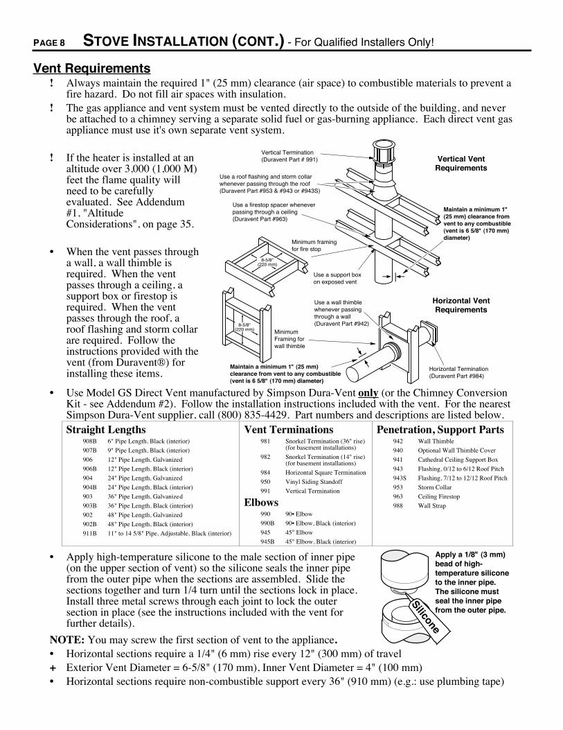
Vent Requirements! Always maintain the required 1" (25 mm) clearance (air space) to combustible materials to prevent a
fire hazard. Do not fill air spaces with insulation.! The gas appliance and vent system must be vented directly to the outside of the building, and never
be attached to a chimney serving a separate solid fuel or gas-burning appliance. Each direct vent gasappliance must use it's own separate vent system.
! If the heater is installed at analtitude over 3,000 (1,000 M)feet the flame quality willneed to be carefullyevaluated. See Addendum#1, "AltitudeConsiderations", on page 35.
¥ When the vent passes througha wall, a wall thimble isrequired. When the ventpasses through a ceiling, asupport box or firestop isrequired. When the ventpasses through the roof, aroof flashing and storm collarare required. Follow theinstructions provided with thevent (from Duravent¨) forinstalling these items.
Use a firestop spacer whenever passing through a ceiling (Duravent Part #963)
Vertical Termination (Duravent Part # 991)
Use a roof flashing and storm collar whenever passing through the roof(Duravent Part #953 & #943 or #943S)
8-5/8"(220 mm)
Use a support box on exposed vent
Vertical Vent Requirements
Use a wall thimble whenever passing through a wall (Duravent Part #942)
Horizontal Termination (Duravent Part #984)
Maintain a minimum 1" (25 mm) clearance from vent to any combustible (vent is 6 5/8" (170 mm) diameter)
Minimum Framing for wall thimble
Horizontal Vent Requirements
Minimum framing for fire stop
8-5/8"(220 mm)
Maintain a minimum 1" (25 mm) clearance from vent to any combustible(vent is 6 5/8" (170 mm) diameter)
¥ Use Model GS Direct Vent manufactured by Simpson Dura-Vent only (or the Chimney ConversionKit - see Addendum #2). Follow the installation instructions included with the vent. For the nearestSimpson Dura-Vent supplier, call (800) 835-4429. Part numbers and descriptions are listed below.Straight Lengths
908B 6" Pipe Length, Black (interior)
907B 9" Pipe Length, Black (interior)
906 12" Pipe Length, Galvanized
906B 12" Pipe Length, Black (interior)
904 24" Pipe Length, Galvanized
904B 24" Pipe Length, Black (interior)
903 36" Pipe Length, Galvanized
903B 36" Pipe Length, Black (interior)
902 48" Pipe Length, Galvanized
902B 48" Pipe Length, Black (interior)
911B 11" to 14 5/8" Pipe, Adjustable, Black (interior)
Vent Terminations981 Snorkel Termination (36" rise)
(for basement installations)
982 Snorkel Termination (14" rise)(for basement installations)
984 Horizontal Square Termination
950 Vinyl Siding Standoff
991 Vertical Termination
Elbows990 90¥ Elbow
990B 90¥ Elbow, Black (interior)
945 45° Elbow
945B 45° Elbow, Black (interior)
Penetration, Support Parts942 Wall Thimble
940 Optional Wall Thimble Cover
941 Cathedral Ceiling Support Box
943 Flashing, 0/12 to 6/12 Roof Pitch
943S Flashing, 7/12 to 12/12 Roof Pitch
953 Storm Collar
963 Ceiling Firestop
988 Wall Strap
¥ Apply high-temperature silicone to the male section of inner pipe(on the upper section of vent) so the silicone seals the inner pipefrom the outer pipe when the sections are assembled. Slide thesections together and turn 1/4 turn until the sections lock in place.Install three metal screws through each joint to lock the outersection in place (see the instructions included with the vent forfurther details).
NOTE: You may screw the first section of vent to the appliance.
Apply a 1/8" (3 mm) bead of high-temperature silicone to the inner pipe. The silicone must seal the inner pipe from the outer pipe.
Silicone
¥ Horizontal sections require a 1/4" (6 mm) rise every 12" (300 mm) of travel+ Exterior Vent Diameter = 6-5/8" (170 mm), Inner Vent Diameter = 4" (100 mm)¥ Horizontal sections require non-combustible support every 36" (910 mm) (e.g.: use plumbing tape)
STOVE INSTALLATION (CONT.) - For Qualified Installers Only! PAGE 9
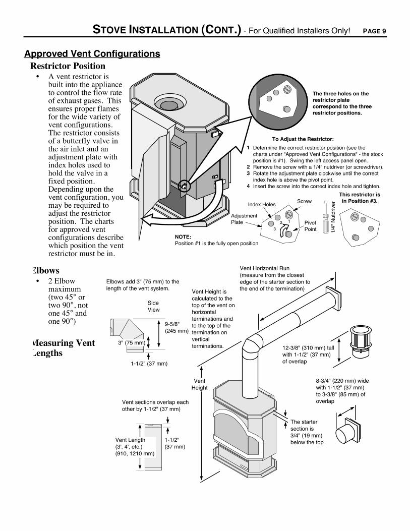
Approved Vent ConfigurationsRestrictor Position
¥ A vent restrictor isbuilt into the applianceto control the flow rateof exhaust gases. Thisensures proper flamesfor the wide variety ofvent configurations.The restrictor consistsof a butterfly valve inthe air inlet and anadjustment plate withindex holes used tohold the valve in afixed position.Depending upon thevent configuration, youmay be required toadjust the restrictorposition. The chartsfor approved ventconfigurations describewhich position the ventrestrictor must be in.
To Adjust the Restrictor:
1
23
4
The three holes on the restrictor plate correspond to the three restrictor positions.
Determine the correct restrictor position (see the charts under "Approved Vent Configurations" - the stockposition is #1). Swing the left access panel open.Remove the screw with a 1/4" nutdriver (or screwdriver).Rotate the adjustment plate clockwise until the correct index hole is above the pivot point.Insert the screw into the correct index hole and tighten.
NOTE: Position #1 is the fully open position
1/4"
Nut
driv
er
Adjustment Plate
Index Holes
Pivot Point
Screw
12
3
This restrictor is in Position #3.
Elbows¥ 2 Elbow
maximum(two 45° ortwo 90°, notone 45° andone 90°)
Measuring VentLengths
Vent Horizontal Run(measure from the closest edge of the starter section to the end of the termination)Vent Height is
calculated to the top of the vent on horizontal terminations and to the top of the termination on vertical terminations.
Vent Height
Elbows add 3" (75 mm) to the length of the vent system.
Side View
9-5/8"(245 mm)
Vent Length(3', 4', etc.)(910, 1210 mm)
Vent sections overlap each other by 1-1/2" (37 mm)
8-3/4" (220 mm) wide with 1-1/2" (37 mm) to 3-3/8" (85 mm) of overlap
The starter section is 3/4" (19 mm) below the top
12-3/8" (310 mm) tall with 1-1/2" (37 mm) of overlap
3" (75 mm)
1-1/2" (37 mm)
1-1/2" (37 mm)
PAGE 10 STOVE INSTALLATION (CONT.) - For Qualified Installers Only!
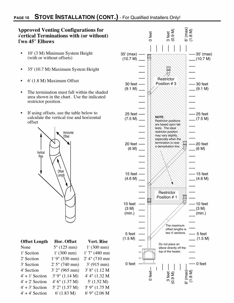
Approved Venting Configurations forVertical Terminations with (or without)Two 45° Elbows
¥ 10' (3 M) Minimum System Height(with or without offsets)
¥ 35' (10.7 M) Maximum System Height
¥ 6' (1.8 M) Maximum Offset
¥ The termination must fall within the shadedarea shown in the chart. Use the indicatedrestrictor position.
¥ If using offsets, use the table below tocalculate the vertical rise and horizontaloffset
Offset Length
Horizontal Offset
Vertical Rise
Offset Length Hor. Offset Vert. RiseNone 5" (125 mm) 1' (300 mm)1' Section 1' (300 mm) 1' 7" (480 mm2' Section 1' 9" (530 mm) 2' 4" (710 mm3' Section 2' 5" (740 mm) 3' (915 mm)4' Section 3' 2" (965 mm) 3' 8" (1.12 M)4' + 1' Section 3' 9" (1.14 M) 4' 4" (1.32 M)4' + 2' Section 4' 6" (1.37 M) 5' (1.52 M)4' + 3' Section 5' 2" (1.57 M) 5' 9" (1.75 M)4' + 4' Section 6' (1.83 M) 6' 9" (2.06 M)
AAAAAAAAAAAAAAAAAAAAAAAAAAAAAAAAAAAAAAAAAAAAAAAAAAAAAAAAAAAAAAAAAAAAAAAAAAAAAAAAAAAAAAAAAAAAAAAAAAAAAAAAAAAAAAAAAAAAAAAAAAAAAAAAAAAA
5 feet(1.5 M)
10 feet(3 M)(min.)
15 feet(4.6 M)
20 feet(6 M)
25 feet(7.5 M)
30 feet(9.1 M)
0 feet
35' (max)(10.7 M)
0 fe
et
3 fe
et(0
.9 M
)
6' (
max
)(1
.8 M
)
5 feet(1.5 M)
0 feet
0 fe
et
Restrictor Position # 1
The maximum offset lengths is two 4' sections.
NOTE:Restrictor positions are based upon lab tests. The ideal restrictor position may vary slightly, especially when the termination is near a demarkation line.
Restrictor Position # 3
Do not place an elbow directly off the top of the heater.
3 fe
et(0
.9 M
)
6' (
max
)(1
.8 M
)
10 feet(3 M)(min.)
15 feet(4.6 M)
20 feet(6 M)
25 feet(7.5 M)
30 feet(9.1 M)
35' (max)(10.7 M)
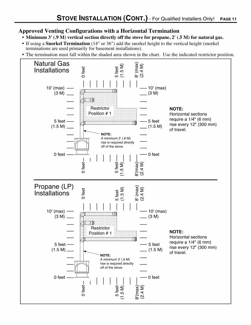
STOVE INSTALLATION (CONT.) - For Qualified Installers Only! PAGE 11
Approved Venting Configurations with a Horizontal Termination¥ Minimum 3' (.9 M) vertical section directly off the stove for propane, 2' (.5 M) for natural gas.¥ If using a Snorkel Termination (14" or 36") add the snorkel height to the vertical height (snorkel
terminations are used primarily for basement installations).¥ The termination must fall within the shaded area shown in the chart. Use the indicated restrictor position.
AAAAAAAAAAAAAAAAAAAAAAAAAAAAAAAAAAA
5 feet(1.5 M)
0 feet
10' (max)(3 M)
0 fe
et
5 feet(1.5 M)
0 feet
0 fe
et
NOTE: Horizontal sections require a 1/4" (6 mm) rise every 12" (300 mm) of travel.
8'(m
ax)
(2.4
M)
NOTE: A minimum 2' (.6 M) rise is required directly off of the stove.
Restrictor Position # 1
8' (
max
)(2
.4 M
)Natural GasInstallations
AAAAAAAAAAAAAAAAAAAAAAAAAAAA
0 feet
0 fe
et
0 feet
0 fe
et
NOTE: A minimum 3' (.9 M) rise is required directly off of the stove.
Restrictor Position # 1
Propane (LP)Installations
5 fe
et(1
.5 M
)
10' (max)(3 M)
5 fe
et(1
.5 M
)
NOTE: Horizontal sections require a 1/4" (6 mm) rise every 12" (300 mm) of travel.
5 feet(1.5 M)
10' (max)(3 M)
5 feet(1.5 M)
8'(m
ax)
(2.4
M)
8' (
max
)(2
.4 M
)
5 fe
et(1
.5 M
)
10' (max)(3 M)
5 fe
et(1
.5 M
)

PAGE 12 STOVE INSTALLATION (CONT.) - For Qualified Installers Only!
Approved Venting Configurations for Vertical Terminations with Two 90° Elbows¥ The termination must fall within the shaded area shown in the chart. Use the indicated restrictor position.
AAAAAAAAAAAAAAAAAAAAAAAAAAAAAAAAAAAAAAAAAAAAAAAAAAAAAAAAAAAAAAAAAAAAAAAAAAAAAAAAAAAAAAAAAAAAAAAAAAAAAAAAAAAAAAAAAAAAAAAAAAAAAAAAAAAAAAAAAAAAAAAAAAAAAAAAAAAAAAAAAAAAAAAAAAAAAAAAAAAAAAAAAAAAAAAAAAAAAAAAAAAAAAAAAAAAAAAAAAAAAAAAAAAAAAAAAA
AAAAAAAAAAAAAAAAAAAAAAAAAAAAAAAAAAAAAAAAAAAAAAAAAAAAAAAAAAAAAAAAAAAAAAAAAAAAAAAAAAAAAAAAAAAAAAAAAAAAAAAAAAAAAAAAAAAAAAAAAAAAAAAAAAAAAAAAAAAAAAAAAAAAAAAAAAAAAAAAAAAAAAAAAAAAAAAAAAAAAAAAAAAAAAAAAAAAAAAAAAAAAAAAAAAAAAAAAAAAAAAAAAAAAAAAAA
AAAAAAAAAAAAAAAAAAAAAAAAAAAAAAAAAAAAAAAAAAAAAAAAAAAAAA
0 feet
5 fe
et(1
.5 M
)
10 fe
et(3
M)
0 fe
et
0 feet
0 fe
et
NOTE: Horizontal sections require a 1/4" (6 mm) rise every 12" (300 mm) of travel.
Restrictor Position # 3
16'(m
ax)
(4.9
M)
8 feet (min.)(2.4 M)
Restrictor Position # 2
Restrictor Position # 1
NOTE:Restrictor positions are based upon lab tests. The ideal restrictor position may vary slightly, especially when the termination is near a demarkation line.
5 feet(1.5 M)
10 feet(3 M)
15 feet(4.6 M)
20 feet(6 M)
25 feet(7.5 M)
30 feet(9.1 M)
35' (max)(10.7 M)
5 feet(1.5 M)
10 feet(3 M)
15 feet(4.6 M)
20 feet(6 M)
25 feet(7.5 M)
30 feet(9.1 M)
35' (max)(10.7 M)
8 feet (min.)(2.4 M)
5 fe
et(1
.5 M
)
10 fe
et(3
M)
16'(m
ax)
(4.9
M)
Do not place an elbow directly off the top of the heater.

STOVE INSTALLATION (CONT.) - For Qualified Installers Only! PAGE 13
Horizontal Vent Termination Requirements (see the illustration below)A Minimum 9" (225 mm) clearance from any door or window
B Minimum 12" (300 mm) above any grade, veranda, porch, deck or balcony
C Minimum 12" (300 mm) from outside corner walls
D Minimum 12" (300 mm) from inside corner walls
E Minimum 11" (275 mm) clearance below unventilated soffits or roof surfacesMinimum 18" (450 mm) clearance below ventilated soffitsMinimum 6" (150 mm) clearance from roof eavesNOTE: Vinyl surfaces require 24" (600 mm)
11Ó Min.
6Ó Min.
Roof Surface
Roof Eaves
F Minimum 18" (450 mm) clearance below a veranda, porch, deck or balcony (must have two open sides)
G Minimum 48" (1220 mm) clearance from any adjacent building
H Minimum 84" (2130 mm) clearance above any grade when adjacent to public walkways or drivewaysNOTE: may not be used over a walkway or driveway shared by an adjacent building
I Minimum 48" (1220 mm) clearance from any mechanical air supply inlet, 72" (1820 mm) for Canada
J Minimum 36" (910 mm) clearance above and 48" (1220 mm) below and to the sides of non-mechanical air supply inlet
K Minimum 36" (910 mm) from the area above the meter/regulator (vent outlet)
L Minimum 36" (910 mm) from the meter/regulator (vent outlet)
C
B
H
E
G A
DF
L
K J
I
NOTE: Measure clearances to the nearest edge of the exhaust hood.
AE
¥ Use the vinyl siding standoff (#950) when installing on an exterior with vinyl siding.
¥ Vent termination must not be located where it will become plugged by snow or other material
¥ These clearances meet UMC-1994 and the CNA/CGA-B149 code standards
Vertical Vent Termination Requirements (see the illustration below)
Roof PitchFlat to 6/126/12 to 8/128/12 to 9/129/12 to 10/1210/12 to 11/1211/12 to 12/1212/12 to 14/1214/12 to 16/1216/12 to 18/1218/12 to 20/1220/12 or greater
Minimum Height*1' (.3 M)*
1.5' (.45 M)*2' (.6 M)
2.5' (.75 M)3.25' (1 M)4' (1.2 M)5' (1.5 M6' (1.8 M)
7' (2.15 M)7.5' (2.25 M)8' (2.45 M)
* In Canada the vent termination must be a minimum 2' (.6 M) tall and 2' (.6 M) above any portion of the roof within 10' (3 M) of the vent.
Use the chart to the right to determine the required vent termination height.
Height
Roof Pitch
Use the vertical termination (Part #991)
Electrical Connection ¥ Plug the power cord into a grounded 120 Volt outlet (do not remove the grounding plug).

PAGE 14 FINALIZING THE INSTALLATION - For Qualified Installers Only!
! Turn the gas control valve to "OFF" prior to conducting any service.
1 Open the door following the instructions below.
Open both the top and bottom latch.
With the pawl free of the strike, the door may be swung open.
Swing the left panel back.
When securing the door, make sure the pawl fits over the strike before tightening.
Strike
PawlDoor Frame
NOTE: Do not overtighten the pawl by screwing it in. This will permanently damage the latch.
FINALIZING THE INSTALLATION (CONT.) - For Qualified Installers Only! PAGE 15
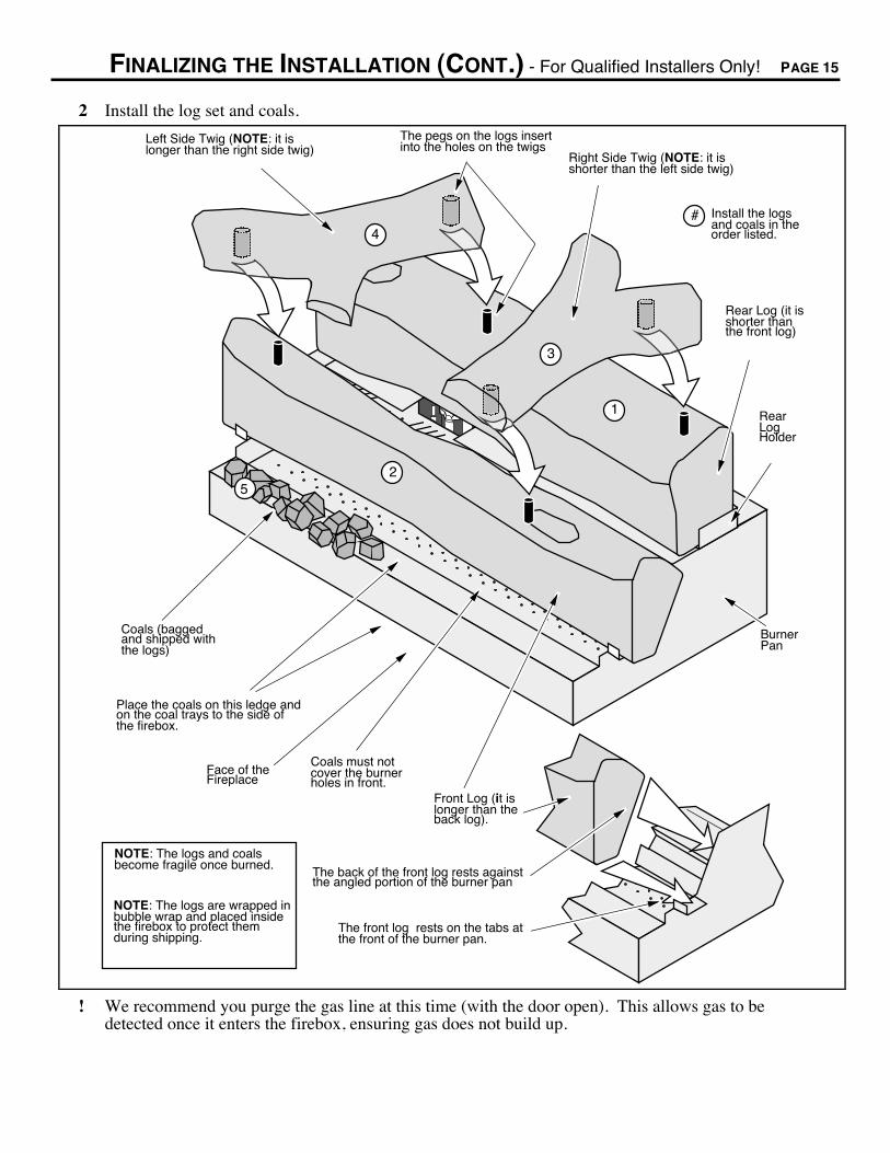
2 Install the log set and coals.
The front log rests on the tabs at the front of the burner pan.
The back of the front log rests against the angled portion of the burner pan
AAAAAAAAAAAAA
AAAAAA
AAAAAAA
AAAAAAAAAAA
Coals must not cover the burner holes in front.
Rear Log (it is shorter than the front log)
Front Log (it is longer than the back log).
Burner Pan
Place the coals on this ledge and on the coal trays to the side of the firebox.
Right Side Twig (NOTE: it is shorter than the left side twig)
Left Side Twig (NOTE: it is longer than the right side twig)
NOTE: The logs and coals become fragile once burned.
NOTE: The logs are wrapped in bubble wrap and placed inside the firebox to protect them during shipping.
The pegs on the logs insert into the holes on the twigs
Rear Log Holder
Coals (bagged and shipped with the logs)
Face of the Fireplace
1
2
3
4# Install the logs
and coals in the order listed.
5
! We recommend you purge the gas line at this time (with the door open). This allows gas to bedetected once it enters the firebox, ensuring gas does not build up.

PAGE 16 FINALIZING THE INSTALLATION (CONT.) - For Qualified Installers Only!
3 Close and secure the door (see step 1).
4 Turn on gas to theheater. Leak test allgas joints prior tostarting theappliance. Start thepilot. Start the mainburner. Leak test allgas joints again.
5 Check the pilot flameto make sure it lookslike the illustration tothe right. Adjust thepilot flame ifnecessary.
6 Let the heater burnfor fifteen minutes.Adjust the air shutter,if necessary, toachieve the correctlooking flame (seethe illustration to theright).
¥ The air shutteradjusts the amount ofair that mixes withthe gas before it exitsthe burner holes. Itis used to fine-tunethe flame fordifferences inaltitude and ventconfiguration.
!If the air shutter is inits fully openposition, yet theflames remain sooty,shut off gas to theheater and contactyour dealer for aremedy.
The pilot flame should impinge the top 3/8Ó (10 mm) of the thermopile. If it does not, you may need to turn the pilot up.
To adjust the pilot flame, remove the cover screw (and gasket) and turn the needle valve. Clockwise lowers the flame while counter-clockwise raises it.
PILOT ADJ
TO L PI
ON
OFF
Standard Screwdriver
Micro (1/16Ó) Standard Screwdriver
A
The cover screw and gasket must be replaced to prevent gas from leaking
Cover Screw
Cover Screw Gasket
Needle Valve
3/8Ó (10 mm)
Thermopile
Pilot Hood
Thermocouple
Gas Control Valve
PILOT ADJ
VE
NT
HI
LO
CorrectFlames should be blue at the base, yellow-orange on the top.
If the flames are too tall or sooty on the ends, push up on the lever.
If the flames are all blue and short, pull down the lever.
Not Enough Air Too Much Air
Locate the air shutter adjustment lever behind the gas control valve. Move it up or down until the flame looks correct. Pushing up gives the flame more air (making it bluer). Pulling it down cuts air down, making it more orange.
NOTE: If the air control is all the way up, yet the flames remain sooty, shut off gas to the fireplace and contact a qualified gas service technician. NOTE: The logs must be installed correctly to
monitor the flame while adjusting the air shutter.
TO
L
PI
ON
OF
F
The flames should burn right off the top of the burner ports (if they are too blue, adjust the air control).
If the flames are lifting, yet the vent configuration is correct, contact your dealer.
Burner Pan
Burner Ports (consists of slots and holes)
If the flames are ghosting, yet the vent configuration is correct, contact your dealer.
! If the vent configuration is installed incorrectly the vent may cause the flames inside the heater to liftor "ghost" Ð a dangerous situation. Inspect the flames after installation to insure proper performance.If the vent configuration is correct, yet the flames are lifting or ghosting, shut off gas to the heaterand contact the dealer for information on remedying the problem.
7 Turn the flame adjust knob to its highest position - the flames should be approximately 12"tall.Check the flame on low position. The flames should burn off of each burner hole. If the heater doesnot work correctly, contact your dealer for a remedy.
8 Give this manual to the home owner and fully explain the operation of this heater.

OPERATING YOUR HEATER PAGE 17
Before You Begin! Read this entire manual before you use your new heater (especially the section "Safety
Precautions" on pages 2 & 3). Failure to follow the instructions may result in propertydamage, bodily injury, or even death.
Location of Controls - See explanation below
Swing the control coverdown to access the gas control valve, igniter, and blower control.
Gas Control Valve
PILOT ADJ
VE
NT
TOL PI
ON
OFF
HI
LO
Gas Control Knob
Flame Adjust Knob
Blower Knob
BL
OW
ER
LO
OFF HIPILOT IGNITER
Pilot Igniter
ON/OFF Switch
The on/off switch is located on the back of the heater.
The Pilot Flame can be found below the back log.
OF
ON
F
On/Off Switch This control is used to turn the main burner on and off.
Gas Control Knob This knob is used to control gas to the heater and for starting the pilot. Thereare three positions, ON, OFF, & PILOT. The pointer directly below the knobindicates the position this knob is in.
Flame Adjust Knob This knob controls the flame height from low ("LO") to high ("HI"). Thepointer to the upper left of the knob points to the position this knob is in.
Pilot Igniter The pilot igniter is used only to start the pilot. When pressed, it sends anelectrical charge to the pilot assembly. This creates a blue spark directly nextto the pilot, igniting the pilot flame.
Blower Knob This knob controls the speed of the internal convection blower that pushes theheated air into the room.
? If using a remote control or thermostat, the On/Off Switch must be left "ON". Turning the On/OffSwitch "OFF" will keep the heater off always.
PAGE 18 OPERATING YOUR HEATER (CONTINUED)
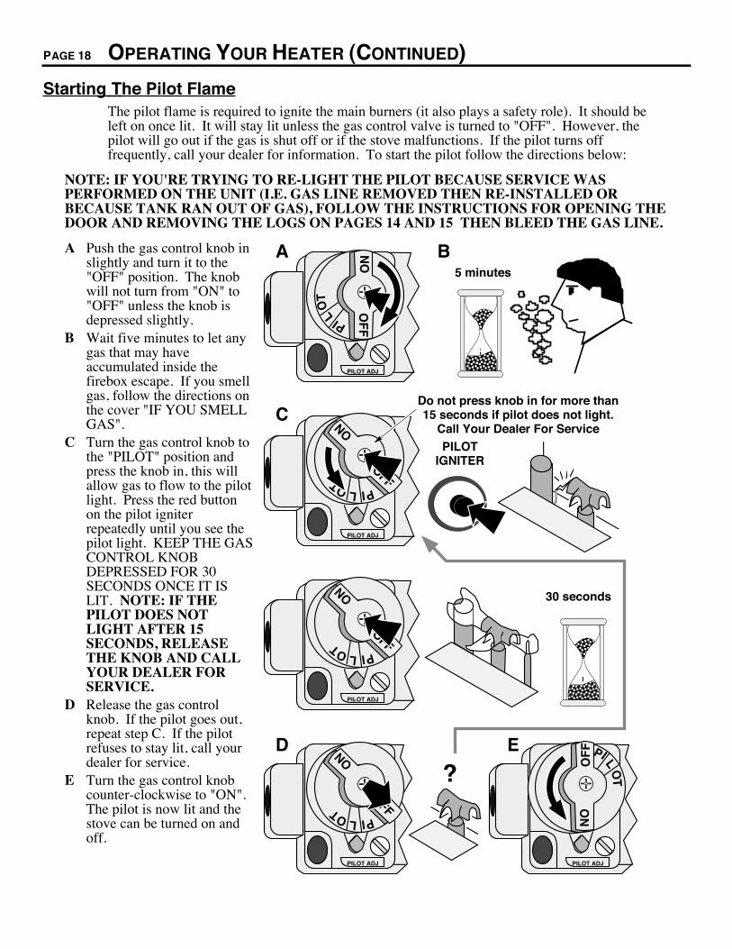
Starting The Pilot FlameThe pilot flame is required to ignite the main burners (it also plays a safety role). It should beleft on once lit. It will stay lit unless the gas control valve is turned to "OFF". However, thepilot will go out if the gas is shut off or if the stove malfunctions. If the pilot turns offfrequently, call your dealer for information. To start the pilot follow the directions below:
NOTE: IF YOU'RE TRYING TO RE-LIGHT THE PILOT BECAUSE SERVICE WASPERFORMED ON THE UNIT (I.E. GAS LINE REMOVED THEN RE-INSTALLED ORBECAUSE TANK RAN OUT OF GAS), FOLLOW THE INSTRUCTIONS FOR OPENING THEDOOR AND REMOVING THE LOGS ON PAGES 14 AND 15 THEN BLEED THE GAS LINE.
A Push the gas control knob inslightly and turn it to the"OFF" position. The knobwill not turn from "ON" to"OFF" unless the knob isdepressed slightly.
B Wait five minutes to let anygas that may haveaccumulated inside thefirebox escape. If you smellgas, follow the directions onthe cover "IF YOU SMELLGAS".
C Turn the gas control knob tothe "PILOT" position andpress the knob in, this willallow gas to flow to the pilotlight. Press the red buttonon the pilot igniterrepeatedly until you see thepilot light. KEEP THE GASCONTROL KNOBDEPRESSED FOR 30SECONDS ONCE IT ISLIT. NOTE: IF THEPILOT DOES NOTLIGHT AFTER 15SECONDS, RELEASETHE KNOB AND CALLYOUR DEALER FORSERVICE.
D Release the gas controlknob. If the pilot goes out,repeat step C. If the pilotrefuses to stay lit, call yourdealer for service.
E Turn the gas control knobcounter-clockwise to "ON".The pilot is now lit and thestove can be turned on andoff.
PILOT ADJ
PILOT ADJ
PILOT IGNITER
T OL PI
ONOFF
PILOT ADJ
T OL PI
ONOFF
AAAAAAAA
AAA
30 seconds
AAAAAA
AAAA
5 minutes
TO
L
PI
ON
OF
F
PILOT ADJ
T OL PI
ONOFF
?
A B
C
D
PILOT ADJ
E
TO
L
PI
ON
OF
F
Do not press knob in for more than 15 seconds if pilot does not light.
Call Your Dealer For Service

OPERATING YOUR HEATER (CONTINUED) PAGE 19
Starting the Heater for the First Time+ Fumes and smoke from the paint curing and oil burning off the steel may occur the first time you
start your heater. This is normal. We recommend you open windows to vent the room.+ Condensation may appear on the glass each time you start the heater - this is normal.+ Blue Flames will occur on the heater when it first comes on. After fifteen minutes the flames will
turn a more realistic yellow and orange color.? Certain installations use a remote "wall switch" to turn the heater on and off. If this is the case, leave
the ON/OFF switch "ON".
Turning the Heater On and Off
OFF
ON
Use this switch to turn the main burner on and off manually.
After the pilot has been started...
See the instructions included with the remote for details on operation.
For systems with thermostats, use this switch to control the temperature (right is hotter, left cooler). Some systems require the on/off switch to be on.
See the instructions included with the remote for changing the battery.
! Do not place any combustible items on top of or directly in front of the heater, even temporarily.The optional thermostat may start the heater causing a combustible item to ignite.
? If the heater turns on and off frequently while using the thermostat, you may want to adjust the flameheight down until it produces just enough heat needed.
Adjusting the Flame Height+ Your heater has an adjustable flame to tailor the look and heat output to your specific needs. It is
adjusted by turning the middle dial on the gas control valve.
Flame Height Adjustment Knob
Index Mark
Turn clockwise to adjust the flame higher, counter-clockwise to lower.
PILOT ADJ
VE
NT
TO L PI
ON
OFFHI
LO
VE
NT
HI
LO

PAGE 20 OPERATING YOUR HEATER (CONTINUED)
Adjusting the Blower Speed+ The blower helps transfer the heat from the heater into the room. It will not turn on until the heater
is up to temperature (approximately 10 minutes after starting). See the illustration below forinstructions on adjusting the blower speed.
BL
OW
ER
LO
OFF HIPILOT IGNITER
Blower Knob
Turn the knob all the way counter-clockwise to turn the blower off. One click clockwise turns the blower to high speed. Turning the knob clockwise from the high position decreases the speed of the blower.
Normal Operating Sounds
Gas Control ValveAs the gas control valve is turned on and off you will hear a dull clicking sound. This is the valve opening up and shutting down.
Blower Snap Disk This part can produce a clicking sound as it turns the blower on and off.
The appliance may creak with change of temperature.
Pilot FlameThe pilot flame, which remains on, makes a very slight "whisper" sound.
Blower This heater uses a blower to push heated air into the room. You will hear the sound of air movement that increases as the speed is increased.
MAINTAINING YOUR HEATER PAGE 21
Cleaning Your Heater! Fingerprints or other marks left on the optional gold surface may become etched in place if they are
not wiped clean prior to turning the stove on. Clean the gold with denatured alcohol and a soft cloth.¥ With the heater cool, use denatured alcohol and a soft cloth to clean gold surfaces. Other cleaners
may leave a film that may become etched into the gold.
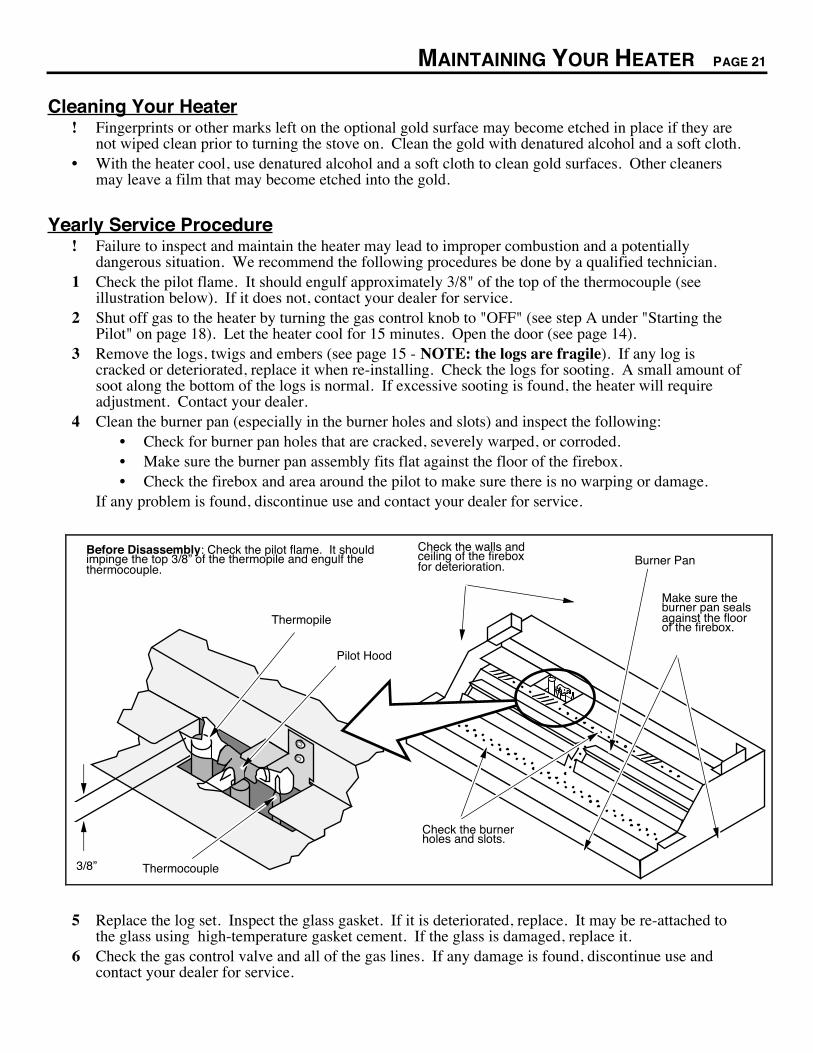
Yearly Service Procedure! Failure to inspect and maintain the heater may lead to improper combustion and a potentially
dangerous situation. We recommend the following procedures be done by a qualified technician.1 Check the pilot flame. It should engulf approximately 3/8" of the top of the thermocouple (see
illustration below). If it does not, contact your dealer for service.2 Shut off gas to the heater by turning the gas control knob to "OFF" (see step A under "Starting the
Pilot" on page 18). Let the heater cool for 15 minutes. Open the door (see page 14).3 Remove the logs, twigs and embers (see page 15 - NOTE: the logs are fragile). If any log is
cracked or deteriorated, replace it when re-installing. Check the logs for sooting. A small amount ofsoot along the bottom of the logs is normal. If excessive sooting is found, the heater will requireadjustment. Contact your dealer.
4 Clean the burner pan (especially in the burner holes and slots) and inspect the following:¥ Check for burner pan holes that are cracked, severely warped, or corroded.¥ Make sure the burner pan assembly fits flat against the floor of the firebox.¥ Check the firebox and area around the pilot to make sure there is no warping or damage.
If any problem is found, discontinue use and contact your dealer for service.
Check the burner holes and slots.
Make sure the burner pan seals against the floor of the firebox.
Check the walls and ceiling of the firebox for deterioration. Burner Pan
Before Disassembly: Check the pilot flame. It should impinge the top 3/8Ó of the thermopile and engulf the thermocouple.
3/8Ó
Thermopile
Pilot Hood
Thermocouple
5 Replace the log set. Inspect the glass gasket. If it is deteriorated, replace. It may be re-attached tothe glass using high-temperature gasket cement. If the glass is damaged, replace it.
6 Check the gas control valve and all of the gas lines. If any damage is found, discontinue use andcontact your dealer for service.

PAGE 22 MAINTAINING YOUR HEATER (CONTINUED)
7 To check the door seal, place a dollar bill along the door perimeter then close and latch the door. Ifthe dollar bill is held in place securely, the door seal is adequate. However, it the dollar bill slidesout easily, you should adjust the door. See the directions below to tighten the door seal.
To tighten the door seal:¥ Open the door (see page 14).¥ Tighten each door latch pawl one turn.¥ Close and latch the door. Open up the right side panel. Loosen the two attachment nuts
on each hinge assembly 1/2 turn. Adjust both adjustment nuts on each hinge assembly 1turn to bring the hinge closer to the rear of the heater (Note: the dimple above the hingeassembly can be used to gauge hinge location). Re-tighten the attachment nuts.
¥ Check the door seal again. If it is still not tight, repeat the above three steps.
Swing the left panel back.
NOTE: Do not overtighten the pawl by screwing it in too far. This will permanently damage the latch.
Rotate the pawl in one turn
Door Frame
Door Frame
Hinge Attachment Nuts (loosen 1/2 turn)
Hinge Adjustment Nuts (turn 1 turn - adjust the nut closest the door frame first)
Dimple (used for gauging hinge position.
8 Start the pilot and turn on the main burner. The flames should be orange/yellow and not touch thetop of the firebox. If the pilot or main burners do not burn correctly, contact your dealer for service.Monitor the blower operation.
9 Remove any debris or vegetation near the vent termination. Contact your dealer if any sooting ordeterioration is found near the vent termination.
TROUBLESHOOTING PAGE 23
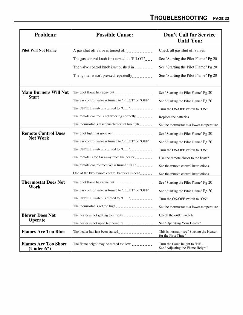
Problem: Possible Cause: Don't Call for ServiceUntil You:
Pilot Will Not Flame A gas shut off valve is turned off
The gas control knob isn't turned to "PILOT"
The valve control knob isn't pushed in
The igniter wasn't pressed repeatedly
Check all gas shut off valves
See "Starting the Pilot Flame" Pg 20
See "Starting the Pilot Flame" Pg 20
See "Starting the Pilot Flame" Pg 20
Main Burners Will NotStart
The pilot flame has gone out
The gas control valve is turned to "PILOT" or "OFF"
The ON/OFF switch is turned to "OFF"
The remote control is not working correctly
The thermostat is disconnected or set too high
See "Starting the Pilot Flame" Pg 20
See "Starting the Pilot Flame" Pg 20
Turn the ON/OFF switch to "ON"
Replace the batteries
Set the thermostat to a lower temperature
Remote Control DoesNot Work
The pilot light has gone out
The gas control valve is turned to "PILOT" or "OFF"
The ON/OFF switch is turned to "OFF"
The remote is too far away from the heater
The remote control receiver is turned "OFF"
One of the two remote control batteries is dead
See "Starting the Pilot Flame" Pg 20
See "Starting the Pilot Flame" Pg 20
Turn the ON/OFF switch to "ON"
Use the remote closer to the heater
See the remote control instructions
See the remote control instructions
Thermostat Does NotWork
The pilot flame has gone out
The gas control valve is turned to "PILOT" or "OFF"
The ON/OFF switch is turned to "OFF"
The thermostat is set too high
See "Starting the Pilot Flame" Pg 20
See "Starting the Pilot Flame" Pg 20
Turn the ON/OFF switch to "ON"
Set the thermostat to a lower temperature
Blower Does NotOperate
The heater is not getting electricity
The heater is not up to temperature
Check the outlet switch
See "Operating Your Heater"
Flames Are Too Blue The heater has just been started This is normal - see "Starting the Heaterfor the First Time"
Flames Are Too Short(Under 6")
The flame height may be turned too low Turn the flame height to "HI" -See "Adjusting the Flame Height"
PAGE 24 TROUBLESHOOTING (CONTINUED)
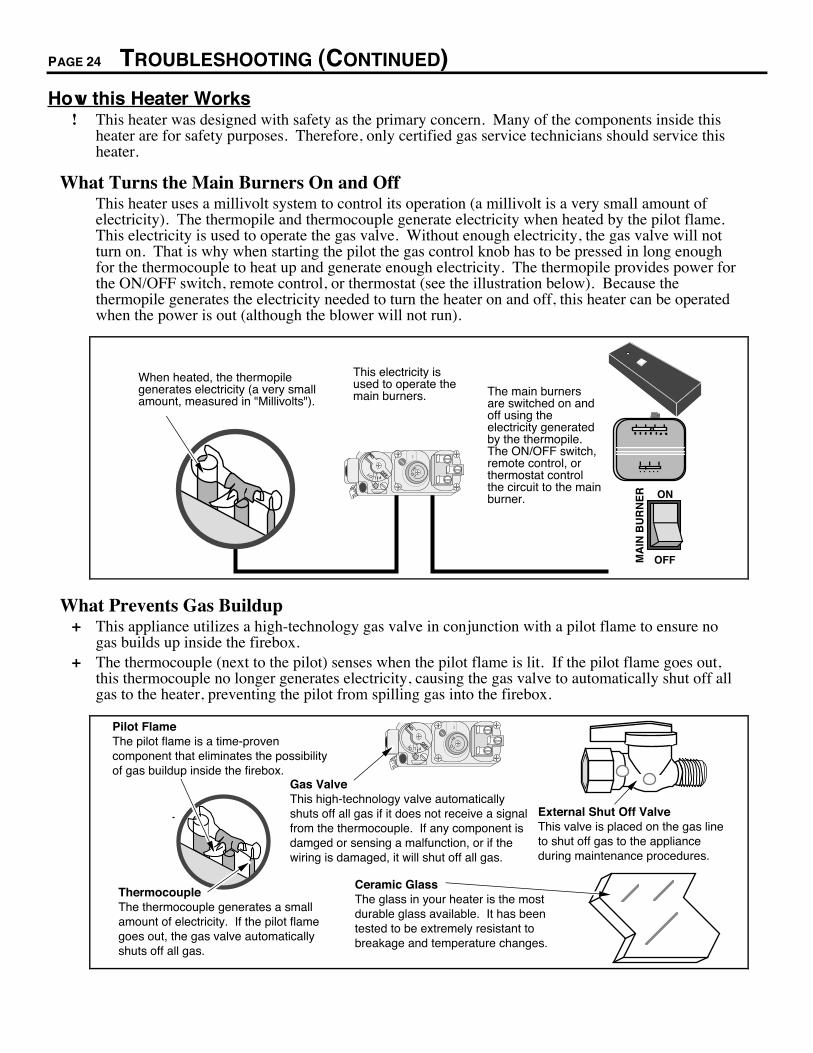
How this Heater Works! This heater was designed with safety as the primary concern. Many of the components inside this
heater are for safety purposes. Therefore, only certified gas service technicians should service thisheater.
What Turns the Main Burners On and OffThis heater uses a millivolt system to control its operation (a millivolt is a very small amount ofelectricity). The thermopile and thermocouple generate electricity when heated by the pilot flame.This electricity is used to operate the gas valve. Without enough electricity, the gas valve will notturn on. That is why when starting the pilot the gas control knob has to be pressed in long enoughfor the thermocouple to heat up and generate enough electricity. The thermopile provides power forthe ON/OFF switch, remote control, or thermostat (see the illustration below). Because thethermopile generates the electricity needed to turn the heater on and off, this heater can be operatedwhen the power is out (although the blower will not run).
When heated, the thermopile generates electricity (a very small amount, measured in "Millivolts").
This electricity is used to operate the main burners. The main burners
are switched on and off using the electricity generated by the thermopile. The ON/OFF switch, remote control, or thermostat control the circuit to the main burner. ON
OFFMA
IN B
UR
NE
RPILOT ADJ
VE
NT
T OL PI
ON
OFF
HILO
What Prevents Gas Buildup+ This appliance utilizes a high-technology gas valve in conjunction with a pilot flame to ensure no
gas builds up inside the firebox.+ The thermocouple (next to the pilot) senses when the pilot flame is lit. If the pilot flame goes out,
this thermocouple no longer generates electricity, causing the gas valve to automatically shut off allgas to the heater, preventing the pilot from spilling gas into the firebox.
Ceramic GlassThe glass in your heater is the most durable glass available. It has been tested to be extremely resistant to breakage and temperature changes.
Gas ValveThis high-technology valve automatically shuts off all gas if it does not receive a signal from the thermocouple. If any component is damged or sensing a malfunction, or if the wiring is damaged, it will shut off all gas.
Pilot FlameThe pilot flame is a time-proven component that eliminates the possibility of gas buildup inside the firebox.
ThermocoupleThe thermocouple generates a small amount of electricity. If the pilot flame goes out, the gas valve automatically shuts off all gas.
External Shut Off ValveThis valve is placed on the gas line to shut off gas to the appliance during maintenance procedures.
PILOT ADJ
VE
NT
TO L PI
ON
OFF
HILO

TROUBLESHOOTING (CONTINUED) PAGE 25
Wiring Diagram
Jumper Wire (Manual
Operation)
Piezo IgniterOrange
On/Off Switch
Thermopile
RedBrown
EPU terminal
White
A
Red
Thermocouple
AAA
Green
120 Volt Grounded A.C. Power Supply
Blower Rheostat
Blower Motor
Chassis Ground
Black
Blower Thermodisk
Green
White
WhiteBlack
Black
Black
Black
120 V. Blower Circuit
Gas Control Valve
Optional Remote ControlOptional
Thermostat
Copper Co-Axial Wire
White
PAGE 26 WARRANTY
To register your TRAVIS INDUSTRIES, INC. Limited Lifetime Warranty, complete the enclosed warranty card and mail it within ten (10) days of theappliance purchase date to: TRAVIS INDUSTRIES, INC., 10850 117th Place N.E., Kirkland, Washington 98033. TRAVIS INDUSTRIES, INC.warrants the Lopi gas appliance to be defect-free in material and workmanship from the date of purchase as follows:
YEAR 1-COVERAGE: PARTS & LABOR1. Stove body, component parts & all accessories are covered for one year (ceramic glass covered for thermal breakage only). Cost of any warranted
component parts and labor to replace or repair warranted component parts are covered. The cost of the dealer service call or travel time is notcovered. Paint & gasketing material are excluded from coverage.
2. One-way freight allowance on pre-authorized repair done at factory is covered.3. In cases where stove must be removed from home for repairs, a partial cost of re-installation of stove is covered (pre-authorization required).
YEARS 2-5-COVERAGE: PARTS & LABOR1. Stove body & component parts are covered . Cost of any warranted component parts and labor to replace or repair warranted component parts are
covered. The cost of the dealer service call or travel time is not covered. All accessories, gold plating, ceramic glass, paint, ceramic logs, gasketing,electrical components, and valves are excluded from coverage.
2. Any of the above excluded component parts may be purchased at 30% discount off manufacturerÕs suggested list price (plus any shipping andhandling charges from your local dealer).
3. New and replacement accessories not available at discounted prices.4. One-way freight allowance on pre-authorized repair done at factory is covered.5. No re-installation coverage.
YEARS 6 & ON-COVERAGE1. The original purchaser can buy stove component parts at 30% discount off suggested retail (plus any shipping & handling charges from your local
dealer) as long as you own the appliance (but a maximum of 5 years after Travis Industries discontinues the designated model).2. The solid brass door is warranted to not warp, crack or peel for as long as you own the appliance. This warranty does not cover tarnishing of the
brass finish . Overfiring or neglect can cause permanent discoloration not covered under warranty (See OwnerÕs Manual for proper care).3. New and replacement accessories not available at discounted prices.4. No coverage on stove body, component parts or labor.5. No freight allowances or re-installation coverage.
CONDITIONS & EXCLUSIONS1. This new Lopi gas appliance must be installed by a competent authorized gas service contractor. It must be installed and operated at all times in
accordance with the installation and operation instructions spelled out in the OwnerÕs Manual. Any alteration, willful abuse, accident, or misuse ofthe product shall nullify this warranty.
2. This warranty is nontransferable, and is made to the ORIGINAL purchaser, provided that the purchase was made through an authorized Lopi dealer.3. Discoloration and some minor movement of certain parts is normal and not a defect and, therefore, not covered under warranty. Overfiring of this
appliance can cause serious damage not covered under warranty and it is the responsibility of the installer to ensure that the appliance is burning asper rating tag at time of installation.
4. The warranty as outlined within this document does not apply to the chimney components or other Non-Travis accessories used in conjunction withthe installation of this product. If in doubt, contact your Authorized Lopi retailer before installation. Travis Industries will not be responsible for...a. Down draft or spillage caused by environmental conditions such as nearby trees, buildings, roof tops, hills or mountains.b. Inadequate ventilation or negative air pressure caused by mechanical systems such as furnaces, fans, clothes dryers, etc.
5. This Warranty is void if:a. The unit has been operated in atmospheres contaminated by chlorine, fluorine or other damaging chemicals.b. The unit is subject to prolong periods of dampness or condensation.c. Any damage to the unit, combustion chamber, heat exchanger or other components due to water, or weather damage which is the result of, but notlimited to, improper chimney/venting installation.
6. Exclusions to this Limited Lifetime Warranty include: injury, loss of use, damage, failure to function due to accident, negligence, misuse, improperinstallation, alteration or adjustment of the manufacturer's settings of components, lack of proper and regular maintenance, damage incurred while theappliance is in transit, alteration, or act of God.
7. This limited warranty excludes damage caused by normal wear and tear, such as paint discoloration or chipping, worn or torn gasketing, corroded orcracked logs, embers, etc. Also excluded is damage to the unit caused by abuse, improper installation, modification of the unit, drilling of the orifices,or the use of fuel other than that indicated on the gas control valve (natural gas or propane). Damage to the gold finish or solid brass finish caused byfingerprints, scratches, items melted to the face, or other external sources left on the gold or solid brass or from the use of cleaners other thandenatured alcohol (gold only) is not covered in this warranty.
8. TRAVIS INDUSTRIES, INC. is free of liability for any damages caused by the appliance, as well as inconvenience expenses and materials.Incidental or consequential damages are not covered by this warranty. In some states, the exclusion of incidental or consequential damage may notapply.
9. This warranty does not cover any loss or damage incurred by the use or removal of any component or apparatus to or from the Lopi gas appliancewithout the express written permission of TRAVIS INDUSTRIES, INC. and bearing a TRAVIS INDUSTRIES, INC. label of approval.
10. Any statement or representation of Lopi products and their performance contained in Lopi advertising, packaging literature, or printed material is notpart of this limited warranty.
11. This warranty is automatically voided if the applianceÕs serial number has been removed or altered in any way. Only the original purchaser of theLopi appliance is covered by this warranty. If the appliance is used for commercial purposes, it is excluded from this warranty.
12. No dealer, distributor, or similar person has the authority to represent or warrant Lopi products beyond the terms contained within this warranty.TRAVIS INDUSTRIES, INC. assumes no liability for such warranties or representations.
13. THIS LIMITED LIFETIME WARRANTY IS THE ONLY WARRANTY SUPPLIED BY TRAVIS INDUSTRIES, INC., THE MANUFACTUREROF THE APPLIANCES. ALL OTHER WARRANTIES, WHETHER EXPRESS OR IMPLIED, ARE HEREBY EXPRESSLY DISCLAIMED ANDPURCHASERÕS RECOURSE IS EXPRESSLY LIMITED TO THE WARRANTIES SET FORTH HEREIN.
IF WARRANTY SERVICE IS NEEDED1. If you discover a problem that you believe is covered by this warranty, you MUST REPORT it to your Lopi dealer WITHIN 30 DAYS, giving them
proof of purchase, the purchase date, and the model name and serial number.2. Travis Industries has the option of either repairing or replacing the defective component.3. If your dealer is unable to repair your applianceÕs defect, he may process a warranty claim through TRAVIS INDUSTRIES, INC., including the name
of the dealership where you purchased the appliance, a copy of your receipt showing the date of the applianceÕs purchase, and the serial number onyour appliance. At that time, you will be asked to ship your appliance, freight charges prepaid, to TRAVIS INDUSTRIES, INC. TRAVISINDUSTRIES, INC., at its option, will repair or replace, free of charge, your Lopi appliance if it is found to be defective in material or workmanshipwithin the time frame stated within this limited warranty. TRAVIS INDUSTRIES, INC. will ship your appliance, freight charges (first five years)prepaid by TRAVIS INDUSTRIES, INC., to your regional distributor, or dealership.
4. Check with your dealer in advance for any costs to you, when arranging a warranty call. Dealers may require you to pay a service or trip charges forany warranty work. This charge can vary from store to store.

LISTING INFORMATION PAGE 27
The safety label can be found inside the right side panel. A copy is shown below.
Beaverton,OR. USA
Tested &Listed by
Heritage BayListed Gas-Fired
Direct Vent Wall Furnace
10850 117th Pl. N.E. Kirkland, WA 98033
L.P. N.G. L.P. N.G.
Input Rate on “HI” (BTU/Hr) ........... 40,000 40,000 Minimum Inlet Pressure (inches W.C.) .............. 11” 5”
Input Rate on “LO” (BTU/Hr) .......... 22,000 19,000 Maximum Inlet Pressure (inches W.C.) ............. 13” 8”
Main Burner Orifice (DMS).............. #49 #31 Manifold Pressure on “HI” (inches W.C.) .......... 10.5” 3.5”
Manifold Pressure on “LO” (inches W.C.)......... 2.7” .9”
This room heater is equipped at the factory for use with natural gas. If conversion to propane (LP) fuel is desired theoptional factory conversion kit must be used.
Blower Electrical Rating: 115 V., 1.5 Amps, 60 Hz FAN TYPE VENTED CIRCULATOR
Manufacture 1997 Jan. Apr. Jul. Oct.Date: 1998 Feb. May Aug. Nov.
1999 Mar. Jun. Sep. Dec. IGN
Tested and certified by OMNI-Test, Inc. to the following standards:USA: ANSI Z21.44-1992 Gas-Fired Gravity and Fan type Direct-Vent Wall Furnace, applicable sections of Z21.11.1-1991 Gas-Fired Vented Room Heaters and
UL 307b Gas Burning Heating Appliances for Mobile Homes and Recreational Vehicles.CANADA: CAN 1-2.19-M81 Gas-Fired Direct-Vent Wall Furnace, CGA IR41 Direct-Vent Gas Fireplace, CGA IR55 additional requirements for Direct-Vent
Fireplaces, and CAN/CGA 2.17-M91 “Gas-Fired Appliances for use at High Altitudes”.
Must be installed in accordance with all local codes, if any; if not, follow ANSI Z223.1-1992 and NFPA 54(88). Installation in Manufactured or Mobile Homes mustconform with: In USA, Manufactured Home Construction and Safety Standard, Title 24 CFR, Part 3280; In Canada, CSA Z240.4 and Gas-Equipped RecreationalVehicles and Mobile Housing. This model is designed to operate on natural gas, or propane (LP). This appliance uses a millivolt-type control system consisting ofa gas control valve/regulator, a standing pilot burner assembly, a thermopile, a piezo ignitor, and the ON/OFF switch. THIS UNIT DOES NOT REQUIRE 110 VOLTPOWER TO OPERATE. All exhaust gases must be vented outside the structure of the living-area. Combustion air is drawn from outside the living-area structure.This appliance may be installed in Manufactured Housing only after the home is site located.
WARNINGS:Improper installation, adjustment, alteration, service or maintenance can cause injury or property damage. Refer to the information in the owner’s and installationmanual provided with this appliance. For assistance or additional information consult a qualified installer, service agency or the gas supplier.Installation and repair should be performed by a qualified service person. The appliance should be inspected before use and at least annually by a qualifiedservice person. More frequent cleaning may be required where excessive lint from material like carpeting and bedding is present. The control compartment, theburner compartment and all circulating air passageways of the appliance must be kept clean and clear at all times.Due to high temperatures, the appliance should be located out of traffic and away from furniture and draperies.This appliance must not be connected to a chimney flue servicing a separate solid fuel burning appliance.This room heater is a Direct-Vent Gas-Fired appliance. DO NOT burn wood or other material in this heater.Children and adults should be alerted to the hazards of high surface temperature and should stay away to avoid flesh burns or clothing ignition.Young children should be carefully supervised at all times when they are in the same room as the appliance.
CAUTION:All safety screen or guard components removed for servicing, must be replaced prior to operating the appliance.Clothing or other flammable material should not be placed on or near the appliance.Risk of electrical shock. Switch the household breaker off or remove fuse before servicing unit.Use Simpson DURA-VENT direct vent system (Model GS) to vent this appliance to the exterior (direct discharge only without duct connection).
Report No. 028-S-14-5
Minimum Clearances toCombustibles
IN MMUnit to Sidewall . . . . . . . . . 8” 200Unit to Backwall . . . . . . . . . 3” 75Unit to Cornerwall . . . . . . . 3” 75Front of Unit . . . . . . . . . . . . 36” 910
Alcove Min. Height . . . . . . 60” 1520Alcove Max Depth . . . . . . . 48” 1220Alcove Min Width . . . . . . . . 43-3/8” 1100

PAGE 28 OPTIONAL EQUIPMENT
LP Conversion InstructionsThe propane conversion kit should be installed prior to installing gas line to ensure proper gas use.1 Open the door (see page 14).2 Remove the burner (see illustration below).
Slide the burner pan to the left until the fixed shutter disengages from the orifice. Place the burner pan aside.
Fixed shutter
Orifice
Burner Pan
Burner Pan Box
Rotate the burner pan upwards.
Removethe burner box front and rear log shelf.
Standard Screwdriver
Burner Box Front
a
b
c
Rear Log Shelf (when replacing, make sure to slide it all the way back).

OPTIONAL EQUIPMENT (CONTINUED) PAGE 29
3 Follow the directions below to remove the natural gas orifice. Apply thread sealant to the LP orifice(#49 - it has "49" stamped on it) and tighten in place with a 1/2" open end wrench. Replace thespring. Slide the adjustable shutter back in place.
Push the adjustable shutter to the left, off the orifice (be careful not to bend the shutter linkage).
1/2"
Wre
nch
Slide the adjustable shutter down, away from the orifice.
Remove the spring
Use a 1/2Ó open end wrench to unscrew the orifice.
Apply thread sealant to the new orifice prior to installation.
Adjustable Shutter
Orifice
Shutter Linkage
a b c
d e f
Burner Orifice Sizing for 36DV and Heritage Bay
NG LP
#31 #49

PAGE 30 OPTIONAL EQUIPMENT (CONTINUED)
4 Remove thepilotassemblywith a 1/4"nutdriver.Use a 7/16"open endwrench tounscrew thepilot tubecompressionnut. Movethe pilot tubedown andaway fromthe pilotassembly.
AAAAAAAAA
7/16
" W
renc
h
AAAAAAAAAAAAAAAAAAAAAAAAAAAAAAAAAAAAAAAAAAAAAAAAAA
AAAAAAAAAAAAAAAAAAAAAAAAAAAAAAAAAAAAAAAAAAAAAAAAAAAAAAAAAAAA
1/4"
Nut
driv
er
AAAAAAAAAAAAAAAAAAAAAAAAAAAAAAAAAAAAAAAAAAAAAAAAAA
AAAAAAAAAAAAAAAAAAAAAAAAAAAAAAAAAAAAAAAAAAAAAAAAAAAAAAAAAAAA
AAAAAAAAAAAAAAAAAAAAAAAAAAAAAAAAAAAAAAAAAAAAA
Pilot TubeDo not kink or excessively bend this tube - this may lead to leaks.
Compression Nut
Pilot Assembly Gasket
5 Remove the pilotorifice. It may beresting on the pilottube or lodgedinside the pilotassembly (tap theassembly fromabove until it fallsout). Place thepropane pilot orificeonto the pilot tube(the LP orifice is.016" diameter - ithas "16" stamped onit). Insert the pilottube (with orifice)into the pilot tubeport and tighten thecompression nutuntil tight. NOTE:Leak test thisconnection afterthe heater isinstalled and gas isconnected.
The pilot tube connections are a common location for gas leaks. Take special care on these gas connections and leak test at both connections after installing.
WARNING:
1 6
P
L
LP Pilot Orifice
NG Pilot Orifice
2 1
N
Make sure the pilot orifice fits over the compression sleeve.
AAAAAAAAAA
AAAAAAA
AAAAAAAAAAAAAAAAAAAAAAAAAAAAAAAAAAAAAAAAAAAAAAAAAA
AAAAAAAAAAAAAAAAAAAAAAAAAAAAAAAAAAAAAAAAAAAAAAAAAAAAAAAAAAAA
AAAAAAAAAAAAAAAAAAAAAAAAAAAAAAAAAAAAAAAAAAAAA
Pilot Tube
Compression Nut
Compression Sleeve
Pilot Orifice
Pilot Tube Port on Pilot Assembly
Pilot Assembly

OPTIONAL EQUIPMENT (CONTINUED) PAGE 31
6 Replace the pilot assembly (follow the instructions in step 4 in reverse order). Make sure the pilotassembly gasket is placed correctly.
7 Replace the rear log shelf (see step 2). Install the logs and embers. Close the door.
8 Remove the regulator from the front of the gas control valve. Replace with the propane regulator,using the new gasket and screws included with the regulator. NOTE: Leak test this area after theheater is installed, gas is connected, and the main burner is lit.
These screws hold the regulator in place.NOTE: use the new screws included with the regulator.
Phillips Screwdriver
PILOT ADJ
TOL PI
ON
OFF
VE
NT
HI
LO
VE
NT
HI
LO
Align the regulator gasket so it is flat and the two tabs fit through the two holes on the gasket.
Regulator GasketNOTE: use the new gasket included with the regulator.
LP (propane) regulators have a 11.0 2.7 stamped here.
NOTE: These holes strip easily. Use a hand screwdriver and tighten each screw evenly.
9 Place the included propane label over the naturalgas label on top of the gas control valve.
THIS CONTROL
HAS BEEN CONVERTED TO
LP
10 Make the gas line connection, start the heater and thoroughly leak-test all gas connectionsand the regulator. Check the pilot. Adjust if necessary.
The pilot flame should impinge the top 3/8Ó of the thermopile. If it does not, you may need to turn the pilot up.
3/8Ó
Thermopile
Pilot Hood
Thermocouple
To adjust the pilot flame, remove the cover screw (and gasket) and turn the needle valve. Clockwise lowers the flame while counter-clockwise raises it.
PILOT ADJ
TO L PI
ON
OFF
Standard Screwdriver
Micro (1/16Ó) Standard Screwdriver
A
The cover screw and gasket must be replaced to prevent gas from leaking
Cover Screw
Cover Screw Gasket
Needle Valve

PAGE 32 OPTIONAL EQUIPMENT (CONTINUED)
Thermostat (Part # 99300650) ! Do not connect 120 VAC to the gas control valve or wiring of this unit.
1 Route the thermostat wire through the back of the right side panel (there is a hole beneath the on/off switch) and attach to the on/offswitch (see the illustration below).
Remove the green jumper wire.
Back of on/off switch
Attach the quick connects from the wire to the two posts on the on/off switch (orientation does not matter).
c
d
Back of on/off switch
Open the right side panel.a
Route the wire through the hole below the on/off switch.
b
2 Pull through all the slack on the wire (you may wish to wrap the wire in electrical tape to prevent damage to the wire). Determine alocation for the thermostat that is within range of the 50' length of thermostat wire. It should be centralized in the room and awayfrom the heater. The wire may be routed externally on the wall or behind the wall (preferred).
3 Cut the thermostat wire so there is approximately 6" of slack (NOTE: Do not splice thermostat wires togetherÐthis leads to too muchelectrical resistance). Expose 1/2" off each wire of the thermostat wire. Attach the exposed wire to the clips on the back of thethermostat using a screwdriver.
Run the thermostat wire through the wall (cut off excess wire, leaving 6" of slack)
Expose 1/2" of wire and attach to the two connections on the back of the thermostat (use a screwdriver). Orientation does not matter.
Wall
Back Side of Thermostat
4 Pull the cover off the thermostat. Place the thermostat in location and attach it to the wall through the two obround holes (use theappropriate screws for the type of wall it is being attached to). Replace the cover on the thermostat to complete the installation.
Pull the cover off the thermostat to expose the holes for mounting the thermostat.
Use the appropriate screws to mount the thermostat to the wall.
OPTIONAL EQUIPMENT (CONTINUED) PAGE 33
Remote Thermostat
! Do not connect 110-120 VAC to the gas control valve or wiring system of this unit.
¥ Follow the instructions included with the remote thermostat for installation.
IMPORTANT OPERATIONAL NOTE FOR REMOTE THERMOSTAT USE:
Included with the remote thermostat is a set of instructions that should be given to the homeowner.Please be aware that the remote thermostat has a 1 to 2 minute lag time between the time thethermostat is turned up and the heater turns on.
PAGE 34 OPTIONAL EQUIPMENT (CONTINUED)
ADDENDUM PAGE 35
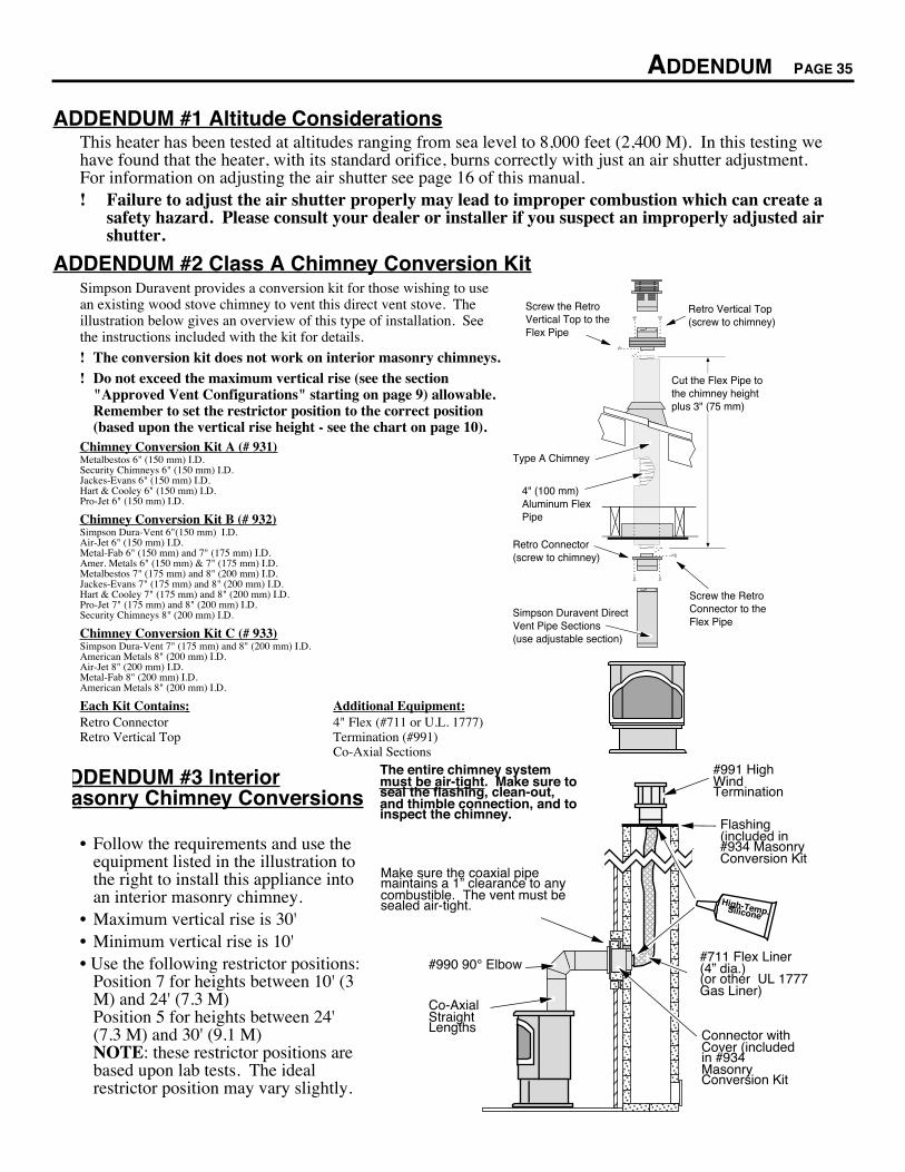
ADDENDUM #1 Altitude ConsiderationsThis heater has been tested at altitudes ranging from sea level to 8,000 feet (2,400 M). In this testing wehave found that the heater, with its standard orifice, burns correctly with just an air shutter adjustment.For information on adjusting the air shutter see page 16 of this manual.! Failure to adjust the air shutter properly may lead to improper combustion which can create a
safety hazard. Please consult your dealer or installer if you suspect an improperly adjusted airshutter.
ADDENDUM #2 Class A Chimney Conversion KitSimpson Duravent provides a conversion kit for those wishing to usean existing wood stove chimney to vent this direct vent stove. Theillustration below gives an overview of this type of installation. Seethe instructions included with the kit for details.
! The conversion kit does not work on interior masonry chimneys.! Do not exceed the maximum vertical rise (see the section
"Approved Vent Configurations" starting on page 9) allowable.Remember to set the restrictor position to the correct position(based upon the vertical rise height - see the chart on page 10).
Chimney Conversion Kit A (# 931)Metalbestos 6" (150 mm) I.D.Security Chimneys 6" (150 mm) I.D.Jackes-Evans 6" (150 mm) I.D.Hart & Cooley 6" (150 mm) I.D.Pro-Jet 6" (150 mm) I.D.
Chimney Conversion Kit B (# 932)Simpson Dura-Vent 6"(150 mm) I.D.Air-Jet 6" (150 mm) I.D.Metal-Fab 6" (150 mm) and 7" (175 mm) I.D.Amer. Metals 6" (150 mm) & 7" (175 mm) I.D.Metalbestos 7" (175 mm) and 8" (200 mm) I.D.Jackes-Evans 7" (175 mm) and 8" (200 mm) I.D.Hart & Cooley 7" (175 mm) and 8" (200 mm) I.D.Pro-Jet 7" (175 mm) and 8" (200 mm) I.D.Security Chimneys 8" (200 mm) I.D.
Chimney Conversion Kit C (# 933)Simpson Dura-Vent 7" (175 mm) and 8" (200 mm) I.D.American Metals 8" (200 mm) I.D.Air-Jet 8" (200 mm) I.D.Metal-Fab 8" (200 mm) I.D.American Metals 8" (200 mm) I.D.
Each Kit Contains: Additional Equipment:Retro Connector 4" Flex (#711 or U.L. 1777)Retro Vertical Top Termination (#991)
Co-Axial Sections
Type A Chimney
Simpson Duravent Direct Vent Pipe Sections(use adjustable section)
Screw the Retro Vertical Top to the Flex Pipe
Retro Vertical Top (screw to chimney)
Screw the Retro Connector to the Flex Pipe
Retro Connector(screw to chimney)
4" (100 mm) Aluminum Flex Pipe
Cut the Flex Pipe to the chimney height plus 3" (75 mm)
DDENDUM #3 Interior asonry Chimney Conversions
¥ Follow the requirements and use theequipment listed in the illustration tothe right to install this appliance intoan interior masonry chimney.
¥ Maximum vertical rise is 30'¥ Minimum vertical rise is 10'¥ Use the following restrictor positions:
Position 7 for heights between 10' (3M) and 24' (7.3 M)Position 5 for heights between 24'(7.3 M) and 30' (9.1 M)NOTE: these restrictor positions arebased upon lab tests. The idealrestrictor position may vary slightly.
AAAAAAAAAA
AAA
AAAAAAAAAAA
AAAA
AAAAAAAAAAAAAAAAAAAAAA
AAAAAAAA
AAAAAA
AA
AAAA
AAAAA
AAAAAAAAAAAAAA
AAAA
The entire chimney system must be air-tight. Make sure to seal the flashing, clean-out, and thimble connection, and to inspect the chimney.
#711 Flex Liner (4Ó dia.)(or other UL 1777 Gas Liner)
Co-Axial Straight Lengths
#991 High Wind Termination
#990 90¡ Elbow
Flashing (included in #934 Masonry Conversion Kit
Make sure the coaxial pipe maintains a 1Ó clearance to any combustible. The vent must be sealed air-tight. High-Temp. Silicone
Connector with Cover (included in #934 Masonry Conversion Kit

PAGE 36 INDEX 270603
Adjusting the Blower Speed.................................... 20
Adjusting the Flame Height..................................... 19
AFUE................................................................. 5
Air Shutter Adjustment........................................... 16
Alcoves .............................................................. 7
Altitude Considerations.......................................... 35
Amperage (of blower)............................................ 5
Blower Speed ...................................................... 20
BTU Output......................................................... 5
Burn Rate ........................................................... 5
Burner Pan Installation .......................................... 28
Cap (vent termination) ........................................... 13
Class A Chimney Conversion Kit ............................. 35
Cleaning Your Heater............................................ 21
Clearances ......................................................... 6
Condensation ...................................................... 19
Controls.............................................................. 17
Dimensions ......................................................... 5
Door Opening ..................................................... 14
Efficiency............................................................ 5
Elbows ............................................................... 9
Electrical Connection ............................................ 13
Electrical Specifications ......................................... 5
Emissions ........................................................... 5
Flame Height....................................................... 16
Floor Protection Requirements ................................ 7
Fuel................................................................... 5
Fumes................................................................ 19
Gas Control Valve (Location) .................................. 17
Gas Inlet Installation ............................................. 7
Gas Leak......................................See Inst. on Cover
Gas Line Connection............................................. 7
Gas Smell.....................................See Inst. on Cover
Heating Capacity.................................................. 5
High Wind Vertical Terminations.............................. 13
Horizontal Vent Termination Requirements ................ 13
How to Measure Vent Lengths ................................ 9
Installation Options ............................................... 5
Installation Preparation .......................................... 6
Leaking Gas..................................See Inst. on Cover
Lifting Flames ...................................................... 16
Listing Label (Safety Label) .................................... 27
Log Installation .................................................... 15
Maintaining Your Stove's Appearance....................... 21
Natural Gas Verses Propane .................................. 2
On/Off Operation.................................................. 19
On/Off Switch (Location) ........................................ 17
Operating Sounds ................................................ 20
Order of Installation .............................................. 6
Packing Lists ....................................................... 6
Paint Curing ........................................................ 19
Pilot (starting) ...................................................... 18
Pilot Flame (Location) ........................................... 17
Pressure (of gas).................................................. 7
Purging Gas Line (with door open) ........................... 15
Remote Control Thermostat Installation .................... 33
Required Components for Installation ...................... 6
Restrictor Adjustment ............................................ 9
Safety Label ........................................................ 27
Safety Precautions ............................................... 2
Silicone Vent Sections........................................... 8
Snorkel Terminations ............................................ 8
Sounds .............................................................. 20
Starting The Pilot Flame ........................................ 18
Starting the Heater for the First Time ........................ 19
Stove Placement Requirements .............................. 7
Table of Contents ................................................. 4
Thermostat Installation .......................................... 32
Troubleshooting Table........................................... 23
Vent Configurations .............................................. 9
Vent Part #'s........................................................ 8
Vent Requirements ............................................... 8
Vertical Vent Termination Requirements ................... 13
Warranty............................................................. 26
Water (on glass - see starting the heater) .................. 19
Wiring Diagram.................................................... 25
Yearly Service Procedure....................................... 21